WO2015128896A1 - 攻撃検知装置、攻撃検知方法、及び攻撃検知プログラム - Google Patents
攻撃検知装置、攻撃検知方法、及び攻撃検知プログラム Download PDFInfo
- Publication number
- WO2015128896A1 WO2015128896A1 PCT/JP2014/001000 JP2014001000W WO2015128896A1 WO 2015128896 A1 WO2015128896 A1 WO 2015128896A1 JP 2014001000 W JP2014001000 W JP 2014001000W WO 2015128896 A1 WO2015128896 A1 WO 2015128896A1
- Authority
- WO
- WIPO (PCT)
- Prior art keywords
- event
- stage
- attack
- information
- observed
- Prior art date
Links
Images


Classifications
-
- G—PHYSICS
- G06—COMPUTING; CALCULATING OR COUNTING
- G06F—ELECTRIC DIGITAL DATA PROCESSING
- G06F21/00—Security arrangements for protecting computers, components thereof, programs or data against unauthorised activity
- G06F21/50—Monitoring users, programs or devices to maintain the integrity of platforms, e.g. of processors, firmware or operating systems
- G06F21/55—Detecting local intrusion or implementing counter-measures
- G06F21/554—Detecting local intrusion or implementing counter-measures involving event detection and direct action
-
- G—PHYSICS
- G06—COMPUTING; CALCULATING OR COUNTING
- G06F—ELECTRIC DIGITAL DATA PROCESSING
- G06F21/00—Security arrangements for protecting computers, components thereof, programs or data against unauthorised activity
- G06F21/50—Monitoring users, programs or devices to maintain the integrity of platforms, e.g. of processors, firmware or operating systems
- G06F21/55—Detecting local intrusion or implementing counter-measures
-
- H—ELECTRICITY
- H04—ELECTRIC COMMUNICATION TECHNIQUE
- H04L—TRANSMISSION OF DIGITAL INFORMATION, e.g. TELEGRAPHIC COMMUNICATION
- H04L63/00—Network architectures or network communication protocols for network security
- H04L63/14—Network architectures or network communication protocols for network security for detecting or protecting against malicious traffic
- H04L63/1408—Network architectures or network communication protocols for network security for detecting or protecting against malicious traffic by monitoring network traffic
- H04L63/1416—Event detection, e.g. attack signature detection
Definitions
- the present invention relates to an attack detection device that detects an attack performed in a plurality of stages via a network.
- Multistage attack refers to an attacker performing an attack divided into multiple stages for one purpose.
- an event such as an IDS (Intrusion Detection System) alert
- a necessary condition for the event to be established referred to here as an event precondition
- event results There is a technique to define changes (called event results here), and determine whether or not an attack is based on whether or not an event string that connects events such that the event result becomes a precondition for other events can be generated .
- the dependency relation for each event detected in advance is defined.
- the dependency is defined as “there is an actual attack event after the port scan event”.
- preconditions and results are further defined, and another event A provides a result that satisfies the preconditions of one event B If so, B is considered to depend on A. It is possible to determine whether or not a multistage attack has occurred by using the dependency relationship for each event and graphing the observed events according to the dependency relationship.
- Patent Document 1 a method for determining event dependency has already been proposed (for example, Patent Document 1).
- a relationship between event management targets is determined in advance, and the dependency of each management target event is determined.
- the first management target, the second management target that generates a second event depending on the first event that occurred in the first management target, and the second management target When there is a third management target that generates a third event depending on the generated second event, the difference between the occurrence time of the first event and the occurrence time of the third event is obtained, and this difference If the time is within a certain time, it can be determined that there is dependency between the first and third events even if the detection of the second event is missing.
- Non-Patent Document 1 has a problem that an attack that can be detected as an event string if it can be observed is not regarded as an event string, and multistage attack detection is delayed.
- Patent Document 1 when there is a leak in event detection, the dependency relationship between observed events can be determined, but the dependency relationship with an event that has not been observed (the second event). There was a problem that it was impossible to estimate. Further, the method of Patent Document 1 discloses that, when there is an omission in event detection, the dependency relationship of each event management target is held by a process allocation table in order to determine the dependency relationship. For this reason, it is necessary to maintain the dependency relationship of all event management targets, and there is a problem that the dependency relationship of event management targets increases explosively as the number of events to be managed increases.
- the present invention has been made to solve the above-described problems, and by estimating events that cannot be observed and generating an event sequence, the dependency relationship of events including unobserved events can be determined.
- the purpose is to judge.
- the present invention dynamically examines an event having a dependency relationship with the generated event by defining a precondition and a result for the event, and maintains a dependency relationship of all the management targets of the event. By estimating the events that cannot be detected, it is an object to prevent the dependency of the event management target from increasing explosively as the number of events to be managed increases.
- the attack detection apparatus includes an event observed in the information system in the course of an attack on the information system, and an attack progress stage before the event is observed.
- An event stage information storage unit that stores event stage information describing a plurality of events, which is a stage before an event and a stage after the event that is an attack progress stage after the event is observed, and the information
- An observation event notification information receiving unit for receiving observation event notification information for notifying an observation event observed in the system, and event stage information in which the observation event notified by the observation event notification information is described.
- a parameter is defined for whether or not each system can observe the event. If the system cannot observe the event, the event is regarded as observed and By generating event sequences by dynamically estimating dependencies, event sequences can be generated even when the system includes events that cannot be observed, thus preventing detection errors in multistage attacks. There is an effect that can be.
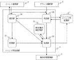
- FIG. 1 is a configuration diagram illustrating a configuration example of an attack detection apparatus according to Embodiment 1.
- FIG. 4 is a flowchart showing a flow of overall processing of the attack detection apparatus according to the first embodiment. It is a figure which shows the example of attack event definition information. It is an example of the attack event definition information 9 stored in the event database 5.
- 4 is a configuration diagram illustrating a configuration example of an event string generation unit 4 according to Embodiment 1.
- FIG. 4 is a flowchart illustrating a process flow of a determination unit 25 according to Embodiment 1.
- 6 is a flowchart showing a process flow of an estimation unit 26 according to the first embodiment.
- 3 is a flowchart showing a flow of processing of a generation unit 28 according to Embodiment 1.
- FIG. 6 is a configuration diagram illustrating a configuration example of an event string generation unit of an attack detection device according to Embodiment 2.
- FIG. 6 is a flowchart showing a flow of processing of an estimation unit 26 according to Embodiment 2.
- FIG. 10 is a configuration diagram illustrating a configuration example of an event string generation unit 4 according to a third embodiment.
- 10 is a flowchart showing a flow of processing of an estimation unit 26 according to Embodiment 3.
- 10 is a flowchart showing a flow of processing of a generation unit 28 according to Embodiment 3.
- FIG. 10 is a configuration diagram illustrating a configuration example of an event string generation unit 4 according to a fourth embodiment.
- 10 is a flowchart showing a flow of processing of an estimation unit 26 according to Embodiment 4.
- FIG. 10 is a configuration diagram illustrating a configuration example of an event string generation unit of an attack detection device according to Embodiment 2.
- FIG. 6 is a flowchart showing a flow of processing
- FIG. 10 is a configuration diagram illustrating a configuration example of an event string generation unit 4 according to a fifth embodiment. It is a figure which shows the example of storage of the determination result table 33 which concerns on Embodiment 5.
- FIG. 10 is a flowchart showing a flow of processing of a determination unit 25 according to Embodiment 5.
- 10 is a flowchart showing a flow of processing of an end determination unit 32 according to Embodiment 5.
- 10 is a flowchart showing a flow of processing of an estimation unit 26 according to Embodiment 5.
- 10 is a flowchart showing a flow of processing of a generation unit 28 according to Embodiment 5. It is a block diagram which shows the example of 1 structure of the attack detection apparatus 1 which concerns on Embodiment 6.
- 10 is a configuration diagram illustrating a configuration example of an event string generation unit 4 according to a sixth embodiment.
- 18 is a flowchart showing a flow of processing of an attack detection apparatus according to the sixth embodiment.
- 18 is a flowchart illustrating a process flow of a determination unit 25 according to Embodiment 6.
- 14 is a flowchart showing a flow of processing of an estimation unit 26 according to Embodiment 6.
- 14 is a flowchart illustrating a processing flow of a generation unit 28 according to Embodiment 6.
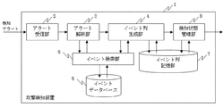
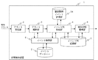
- FIG. 1 is a configuration diagram illustrating a configuration example of an attack detection apparatus according to the first embodiment.
- the attack detection device 1 includes an alert reception unit 2, an alert interpretation unit 3, an event sequence generation unit 4, an event database 5, an event search unit 6, an event sequence storage unit 7, and a detection state management unit 8. .
- the attack detection device 1 detects a multi-stage attack by examining a dependency relationship with an already observed attack event based on a detection alert obtained from the outside and generating an event sequence.
- Alert receiving unit 2 receives an externally detected alert and outputs an alert to alert interpreting unit 3.
- the alert interpretation unit 3 extracts information corresponding to predefined attack event definition information (described later) from the alert received by the alert reception unit 2, interprets it as an attack event, and generates observation event notification information (described later) Then, this observation event notification information (the attack event of the interpretation result) is output to the event string generation unit 4.
- the alert receiving unit 2 and the alert interpreting unit 3 are a configuration example of the observation event notification information receiving unit.
- the event sequence generation unit 4 adds the attack event input from the alert interpretation unit 3 to the event sequence of the observed attack event, and generates a new event sequence.
- the generated new event sequence is registered in the event sequence storage unit 7, and the existing event sequence held in the event sequence generation unit 4 is updated to a new event sequence.
- the event database 5 stores predefined attack event definition information (described later).
- the event database 5 is an example of an event stage information storage unit, and the attack event definition information is an example of event stage information.
- the event search unit 6 searches the event database 5 in accordance with the search request from the alert interpretation unit 3 and the event sequence generation unit 4, and outputs the search results to the alert interpretation unit 3 and the event sequence generation unit 4, respectively.
- the event sequence storage unit 7 stores the event sequence generated by the event sequence generation unit 4.
- the detection state management unit 8 receives the notification of completion of registration / update processing of the event sequence storage unit 7 by the event sequence generation unit 4 as input, and determines whether or not a multistage attack is being performed from the state of the event sequence storage unit 7. If a multi-stage attack has been carried out, notify the outside.
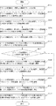
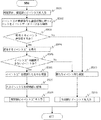
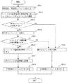
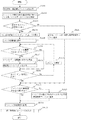
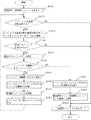
- FIG. 2 is a flowchart showing a process flow of the attack detection apparatus according to the first embodiment.
- the alert receiver 2 receives a detection alert from the outside.
- the detection alert is a warning message transmitted from various devices connected to the network, and is, for example, an IDS alert.
- the detection alert includes information on the destination IP address and port number, the source IP address and port number, protocols such as TCP and UDP, and detected attack events (login, port scan, etc.).
- the alert receiving unit 2 inputs the alert information to the alert interpreting unit 3.
- step S102 the alert interpretation unit 3 requests the event search unit 6 to search for attack event definition information corresponding to the alert.
- the alert interpretation unit 3 generates a search request including the attack event name included in the input alert information, and transmits the search request to the event search unit 6.
- step S103 the event search unit 6 searches the event database 5 and returns attack event definition information corresponding to the alert.
- the event search unit 6 searches the attack event definition information stored in the event database 5 for attack event definition information that matches the attack event included in the search request, and sends the search result to the alert interpretation unit 3. return.
- the attack event definition information is information in which information related to the attack event is defined in advance.
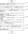
- FIG. 3 is a diagram illustrating an example of attack event definition information. Like the attack event definition information 9 in FIG. 3, the attack event definition information includes a precondition 10, an event 11, an achievement state 12, an attack accuracy 13, and an observation availability 14.
- a precondition for the event 11 to occur when an attack occurs is described in the form of predicate logic. That is, the precondition 10 describes the progress stage (pre-event stage) of the attack before the event 11 is observed.
- the predicate logic indicated by reference numeral 15 in FIG. 3 indicates that “A is logged in to H” as a precondition.
- a and H indicated by reference numeral 15 are variables, and are bound to specific values (for example, “user001”) by values obtained from observation events.
- the event 11 is an event observed in the information system in the process of attacking the information system.
- an event generation source 16 indicates an event generation source targeted by the attack event definition information 9.
- Reference numeral 19 indicates a value permitted as a generation source.
- the variable H is associated with the precondition 15 (the dollar mark ($) at the beginning of “$ H” is a variable H). It is shown that).
- the event type 17 specifies the type of event targeted by the attack event definition information 9.
- a specific event type is designated as 20.
- the event parameter 18 indicates an event parameter. In the event parameter 18, a value targeted by the attack event definition information 9 is specified. In the example shown in FIG. 3, it is required that the parameter named USER at reference numeral 21 has the same value as the variable A indicated by reference numeral 15.
- the event generation source, the event type, and the event parameter are notified as in the attack event definition information 9 of FIG.
- the attack event definition information 9 of FIG. 3 the values of the variables of the event source 16 and the event parameter 18 are not specified, but in the observation event notification information, the values of the variables of the event source 16 and the event parameter 18 are specified. Have been identified.
- the achievement state 12 indicates the state achieved by the attacker when predicate logic occurs when an event that matches the items 16 to 18 of the attack event definition information 9 occurs. That is, the achievement state 12 describes the progress stage (post-event stage) of the attack after an event that matches the items 16 to 18 is observed.
- reference numeral 22 indicates that “user A has obtained the secret of host H”.
- the attack accuracy 13 indicates the accuracy of the attack on the information system when an event that matches the items 16 to 18 of the attack event definition information 9 occurs.
- the accuracy value is defined as 0.5 as indicated by reference numeral 23.
- Observability 14 indicates whether event 11 is an event that the system cannot observe. For example, an event that is not described in the log such as a password leak or an event that does not enter the monitoring target due to the cost or monitoring load corresponds to the unobservable event.
- event 11 is an event that the system cannot observe. For example, an event that is not described in the log such as a password leak or an event that does not enter the monitoring target due to the cost or monitoring load corresponds to the unobservable event.
- “OK” indicating that observation is possible with reference numeral 24 is set. If the observation is not possible, “No” is set.
- the attack event definition information 9 described above is defined in advance for a plurality of events that are considered to occur in a multistage attack, and is stored in the event database 5 in a searchable state.
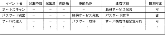
- FIG. 4 is an example of attack event definition information 9 stored in the event database 5.
- information such as an occurrence time, a generation source, and a transmission destination recorded when an attack event is detected is included.
- the generation source is, for example, a transmission source IP address, and the transmission destination URL is recorded as the transmission destination.
- the storage example in FIG. 4 shows a state before an attack event is detected, and the generation time, the generation source, and the transmission destination are blank.
- step S104 the alert interpretation unit 3 interprets the received attack event definition information as an attack event corresponding to the alert.
- the “interpretation” process substitutes the specific values of the event source, event type, and event parameter included in the alert for the attack event definition information of the search result by the event search unit 6, This refers to processing that converts observation events into a data format that can be processed as attack events (observation event notification information).
- step S105 the alert interpretation unit 3 inputs an event to the event sequence generation unit 4.
- the alert interpretation unit 3 inputs the attack event interpreted from the observation event in step S104 to the event sequence generation unit 4.
- step S106 the event string generation unit 4 searches the event string storage unit 7 for an event string to which the input attack event can be added.
- step S107 the event sequence generator 4 determines whether event estimation is necessary.
- the event string generation unit 4 proceeds to a Yes branch when there is no event string that can be added in the event string storage unit 7, and performs event estimation in step S108. Details of processing related to event estimation will be described later. If there is an event sequence that can be added in the event sequence storage unit 7, the event sequence generation unit 4 determines that event estimation is not necessary, and proceeds to branch No.
- step S108 the event sequence generation unit 4 requests the event search unit 6 to search for an event that has the input attack event preconditions in the achieved state, and executes event estimation processing.
- step S109 the event search unit 6 searches the event database 5 and returns attack event definition information corresponding to the search request.
- step S110 the event sequence generation unit 4 generates an event sequence using the attack event definition information searched in step S109, and registers the generated event sequence in the event sequence storage unit 7, or the event The event sequence in the column storage unit 7 is updated.
- step S111 the event sequence generation unit 4 notifies the detection status management unit 8 that the event sequence has been registered or updated in the event sequence storage unit 7.
- the detection state management unit 8 reads the state in the event string storage unit 7 and notifies an alert to the outside if the attack detection condition is satisfied.
- the detection state management unit 8 receives the notification from the event sequence generation unit 4 and examines the event sequence in the event sequence storage unit 7, and the total attack accuracy of each attack event constituting the event sequence is equal to or greater than a threshold value If it is, it is determined that a multi-stage attack has occurred and is notified to the outside.
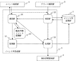
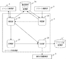
- FIG. 5 is a configuration diagram illustrating a configuration example of the event string generation unit 4 according to the first embodiment.
- the determination unit 25 verifies whether or not the attack event input from the alert interpretation unit 3 can be added to the event sequence registered in the event sequence storage unit 7, and is not observed if it cannot be added to the event sequence. Determine that event estimation is required. If it can be added to the event string, it is determined that estimation of an event that has not been observed is unnecessary. If it is determined that an unobserved event needs to be estimated, the estimating unit 26 estimates an unobserved event. When the estimation is unnecessary, the input attack event is input to the generation unit 28, and an event sequence is generated.
- the estimation unit 26 requests the event search unit 6 to search for an attack event that is dependent on the input attack event, and receives the search result of the event search unit 6.
- the attack event of the search result is an attack event that the system cannot observe, it is determined that the attack event newly obtained by the search is observed.
- the attack event input to the estimation unit 26 is stored in the storage unit 27.
- the attack event regarded as being observed is input to the determination unit 25 to verify whether it can be added to the event string.
- the determination unit 25 determines that estimation is necessary, the determination unit 25 further inputs the estimation unit 26 to estimate an attack event.
- the determination unit 25 determines that the estimation is unnecessary, the input attack event is input to the generation unit 28, and an event sequence is generated.
- the generating unit 28 calls an attack event depending on the input attack event from the storage unit 27 with respect to the attack event input from the determination unit 25 or the estimation unit 26. Thereafter, the input attack event is added to the called attack event to generate a new event sequence.
- the newly generated event sequence is registered in the event sequence storage unit 7.
- the event string storage unit 7 is updated by combining with an existing event string.
- the generation unit 28 notifies the detection state management unit 8 that the event sequence storage unit 7 has been updated by generating the event sequence.
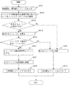
- FIG. 6 is a flowchart illustrating a process flow of the determination unit 25 according to the first embodiment.
- step S201 the alert interpretation unit 3 inputs an event X to the determination unit 25.
- the event X is an attack event (observation event notification information) in step S105 of FIG.
- step S202 the determination unit 25 checks whether or not the event X has a precondition. If the event X has a precondition, the process proceeds to step S203 by branching to Yes. If there is no precondition, the process proceeds to step S209 by branching No.
- step S203 the determination unit 25 requests the event search unit 6 to search for an event sequence including an event having the precondition of the event X in the achieved state, and searches the event sequence storage unit 7.
- step S204 the determination unit 25 determines whether there is an event sequence corresponding to the search request. If there is an event sequence corresponding to the search request, the process proceeds to step S205 due to a Yes branch. . If there is no event sequence corresponding to the search request, the process proceeds to step S207 by branching No.
- step S205 the determination unit 25 determines that the event X can be added to the existing event sequence, and the event X is input to the generation unit 28 in step S206, and the process ends.
- step S204 If the event sequence corresponding to the search request does not exist in step S204, the determination unit 25 determines in step S207 that event estimation is necessary, and the event X is input to the estimation unit 26 in step S208. The process ends.
- step S209 the determination unit 25 determines that the event is a new event sequence, and inputs the input event X to the generation unit 28 in step S210. Then, the process ends.
- the event X input to the determination unit 25 is input to the estimation unit 26 or the generation unit 28 by processing in the determination unit 25.
- FIG. 7 is a flowchart showing a process flow of the estimation unit 26 according to the first embodiment.
- step S301 the determination unit 25 inputs the event X to the estimation unit 26.
- step S302 the estimation unit 26 requests the event search unit 6 to search for an event having the precondition of the event X in the achieved state, and searches the event database 5.
- step S303 the estimation unit 26 determines whether there is an event corresponding to the search request, and if there is an event corresponding to the search request (here, there are no two or more corresponding events). Is assumed to proceed to step S304 due to a Yes branch. If there is no event corresponding to the search request, the process proceeds to step S309 due to a No branch.
- step S304 the estimation unit 26 obtains an event X ′ corresponding to the search request from the event search unit 6.
- step S305 the estimation unit 26 checks whether or not the event X ′ is an event that cannot be observed from the setting of whether or not observation is possible. If the event X ′ is an event that cannot be observed, the process proceeds to step S306 due to a Yes branch. If the event is observable, the process proceeds to step S309 due to a No branch.
- step S306 the estimation unit 26 determines that the event X ′ has already been observed.
- step S307 the estimation unit 26 stores the input event X in the storage unit 27.
- step S308 the estimation unit 26 The event X ′ is input and the process ends.
- step S309 the estimation unit 26 determines that the input event X is a new event X.
- step S310 an event X is input to the generation unit 25, and the process ends.
- FIG. 8 is a flowchart showing a process flow of the generation unit 28 according to the first embodiment.
- step S401 the determination unit 25 or the estimation unit 26 inputs the event X to the generation unit 28.
- step S402 the generation unit 28 confirms whether or not the input event X is determined as a new event sequence by the determination unit 25 or the estimation unit 26. If it is determined as a new event sequence, Yes. Advances to step S403. If it is determined that the event sequence is not a new event sequence, the process proceeds to step S406 due to a No branch.
- step S403 the generation unit 28 calls an event having a dependency relationship with the event X from the storage unit 27.
- the dependency relationship is determined by the event precondition stored in the storage unit 27 and the achievement state relationship.
- step S404 the generation unit 28 generates an event sequence from the preconditions and achievement states of each event called from the storage unit 27, and registers the event sequence in the event sequence storage unit 7 as a new event sequence.
- step S405 the generation unit 28 notifies the detection state management unit 8 that the event string storage unit 7 has been updated, and the process ends.
- step S402 If it is determined in step S402 that the event sequence is not a new event sequence, the generation unit 28 can add the input event X to the existing event sequence by the determination unit 25 or the estimation unit 26 in step S406. If it is determined that it has been determined and it is determined that addition is possible, the process proceeds to step S407 due to a Yes branch. If it is determined that addition is not possible, the process ends due to a No branch.
- step S407 the generation unit 28 calls an event having a dependency relationship with the event X from the storage unit 27.
- the dependency relationship is determined by the event precondition stored in the storage unit 27 and the achievement state relationship.
- step S ⁇ b> 408 the generation unit 28 adds the event X to the event sequence including the event having the precondition for the input event X in the achieved state.
- step S409 the generation unit 28 generates an event sequence from the preconditions and achievement states of each event called from the storage unit 27, and sequentially adds the event sequence to the event sequence added with the event X in step S408. Do.
- step S410 the generation unit 28 updates the event sequence before the addition in the event sequence storage unit 7 with the event sequence after the addition, performs the process of step S405, and ends the process.
- the invention of the first embodiment defines parameters for whether or not each system can observe the event, and if the system cannot observe the event, the event is observed. It is considered that the event sequence can be generated even if the system includes events that the system cannot observe by dynamically estimating the dependency relationship with the corresponding event and generating the event sequence. There is an effect that it is possible to prevent omission of detection of a multistage attack.
- Embodiment 2 FIG. In Embodiment 1 above, an event sequence is generated assuming that an event that cannot be observed by the system has occurred. In Embodiment 2, when an event A cannot be observed, When both event B satisfying the pre-conditions and event X having the achievement condition of event A as the pre-conditions can be observed, an event sequence is generated by assuming that event A has occurred, and the detection accuracy is further improved. The form is shown.
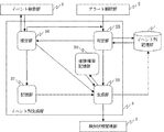
- FIG. 9 is a configuration diagram illustrating a configuration example of an event sequence generation unit of the attack detection apparatus according to the second embodiment.
- the event string generation unit 4 has the same configuration as that of the first embodiment with respect to the determination unit 25, the storage unit 27, and the generation unit 28.
- the estimation unit 26 and the observation standby event storage unit 29 will be described.
- the estimation unit 26 requests the event search unit 6 to search for an event having a dependency relationship with the input event X. As a result of the search, if the obtained event A is an event that cannot be observed by the system, the event A is stored in the observation standby event storage unit 29. At this time, the event X input to the estimation unit 26 is stored in the storage unit 27.
- the estimation unit 26 inputs an event A that cannot be observed to the determination unit 25, and determines whether it can be added to the event sequence.
- Event A is considered to have occurred and an event sequence is generated.
- the estimation unit 26 determines whether estimation cannot be added to the event string (an event having an irrelevant relationship with the event A that cannot be observed has been observed). If not, the event A that cannot be observed is input to the estimation unit 26 again. At this time, since the event A input to the estimation unit 26 already exists in the observation standby event storage unit 27, the estimation unit 26 does not generate the event A stored in the observation standby event storage unit 27.
- the event X first input to the estimation unit is determined to be a new event sequence.
- the event is determined to be a new event sequence, the input attack event is input to the generation unit 28, and an event sequence is generated.
- the attack event output from the alert interpretation unit 3 is input to the determination unit 25.
- movement of the determination part 25 it is the same as that of FIG.
- the attack event input to the determination unit 25 is input to the estimation unit 26 or the generation unit 28 by processing in the determination unit 25.
- FIG. 10 is a flowchart showing a process flow of the estimation unit 26 according to the second embodiment.
- step S501 the determination unit 25 inputs the event X to the estimation unit 26.
- step S302 the estimation unit 26 determines whether or not the input event X exists in the observation standby event storage unit 27. If there is no event X, the process proceeds to step S503 due to a Yes branch. If the input event X exists in the observation standby event storage unit 27, the process proceeds to step S510 by branching No.
- step S503 the estimation unit 26 requests the event search unit 6 to search for an event having the precondition of the event X in the achieved state, and searches the event database 5.
- step S504 the estimation unit 26 determines whether or not there is an event corresponding to the search request, and if there is an event corresponding to the search request (here, two or more corresponding events do not exist). Is assumed to proceed to step S505 due to a Yes branch. If there is no event corresponding to the search request, the process proceeds to step S511 by branching No.
- step S505 the estimation unit 26 obtains an event X ′ corresponding to the search request from the event search unit 6.
- step S506 the estimation unit 26 confirms whether or not the event X ′ is an event that cannot be observed from the setting of whether or not observation is possible. If the event X ′ is an event that cannot be observed, the process proceeds to step S507 due to a Yes branch. If the event is observable, the process proceeds to step S511 due to a No branch.
- step S507 the estimation unit 26 determines that the event X ′ has already been observed.
- step S508 the input event X is stored in the storage unit 27.
- step S509 the determination unit 26 The event X ′ is input and the process ends.
- step S506 If the event X ′ is an event that can be observed in step S506, or if there is no event corresponding to the search request in step S504, in step S511, the estimation unit 26 determines that the input event X is a new event X In step S512, the event X is input to the generation unit 25, and the process ends.
- step S502 If the input event X exists in the observation standby event storage unit 27 in step S502, the estimation unit 26 determines in step S510 that there is an event (depending on the event X stored in the storage unit 27). Replace event X with the previous input event). Thereafter, in step S511, it is determined that the event is a new event. In step S512, the event X is input to the generation unit 25, and the process ends.
- the operation when input to the generation unit 28 by the processing in the determination unit 25 or the estimation unit 26 is the same as in the first embodiment.
- both the event B satisfying the precondition and the event X having the achievement state of the event A as the precondition can be observed. Assuming that event A has occurred, generating an event sequence makes it possible to further improve the detection accuracy.
- Embodiment 3 FIG.
- the event chain occurrence probability is used to evaluate whether the event cannot be observed, and it can be determined that the event has occurred when the occurrence probability exceeds the threshold. Such an embodiment is shown.
- FIG. 11 is a configuration diagram illustrating a configuration example of the event string generation unit 4 according to the third embodiment.
- the event string generation unit 4 includes a chain probability storage unit 30 that stores a chain probability that is a probability that a plurality of events are chained in addition to the configuration of FIG. 5.
- the attack event output from the alert interpretation unit 3 is input to the determination unit 25.
- movement of the determination part 25 it is the same as that of FIG.
- the attack event input to the determination unit 25 is input to the estimation unit 26 or the generation unit 28 by processing in the determination unit 25.
- FIG. 12 is a flowchart showing a process flow of the estimation unit 26 according to the third embodiment.
- the flow of processing of the estimation unit 26 according to Embodiment 3 will be described.
- steps S601 to S605 is the same as the processing of steps S301 to S305 of the estimation unit 26 in the first embodiment shown in FIG.
- step S606 when the event X ′ is an event that cannot be observed by the system, the estimation unit 26 adds information indicating that the event X ′ is an observation determination waiting event.
- This information is, for example, flag information that is set to 1 when waiting for observation determination and set to 0 when not waiting for observation determination.
- steps S607 to S610 is the same as the processing of steps S307 to S310 of the estimation unit 26 in the first embodiment shown in FIG.
- FIG. 13 is a flowchart showing a process flow of the generation unit 28 according to the third embodiment.
- FIG. 13 a processing flow of the generation unit 28 according to the third embodiment will be described.
- step S701 the determination unit 25 or the estimation unit 26 inputs the event X to the generation unit 28.
- step S702 the generation unit 28 calls an event having a dependency relationship with the event X from the storage unit 27.
- the dependency relationship is determined by the event precondition stored in the storage unit 27 and the achievement state relationship.
- step S703 the generation unit 28 generates an event sequence from the preconditions and achievement states of each event called from the storage unit 27.
- step S704 the generation unit 28 calculates the occurrence probability of the observation wait event for the event sequence generated in step S703, based on the already observed events adjacent to each other.
- the occurrence probability is given as a conditional probability when a plurality of events are chained by accumulating data of past event occurrence cases and using these statistical data, for example.
- the chain probabilities of such a plurality of events are stored in the chain probability storage unit 30.
- the generation unit 28 determines that an observation-waiting event in which the calculated occurrence probability is equal to or greater than a set threshold is observed.
- step S ⁇ b> 705 the generation unit 28 confirms whether the input event X is determined as a new event sequence by the determination unit 25 or the estimation unit 26. Advances to step S706. If it is determined that the event sequence is not a new event sequence, the process proceeds to step S709 due to a No branch.
- step S706 the generation unit 28 regenerates the event sequence using only the observed events.
- the regenerated event sequence may be a plurality of event sequences.
- step S707 the generation unit 28 registers the regenerated event sequence in the event sequence storage unit 7.
- step S708 the generation unit 28 notifies the detection state management unit 8 that the event string storage unit 7 has been updated, and the process ends.
- step S705 If it is determined in step S705 that the event sequence is not a new event sequence, the generation unit 28 can add the input event X to the existing event sequence by the determination unit 25 or the estimation unit 26 in step S709. If it is determined that it can be added, the process proceeds to step S710 due to a Yes branch. If it is determined that it cannot be added, the process proceeds to step S707 by branching No, and after registering / updating the event string storage unit, the process of step S708 is performed, and the process ends.
- step S710 the generation unit 28 adds an event sequence that can be combined with the existing event sequence.
- step S711 the generation unit 28 determines whether all the events stored in the storage unit can be added to the existing event sequence. If it is determined that addition is possible, the process proceeds to step S707 due to a Yes branch. After registering / updating the event string storage unit, the process of step S708 is performed, and the process ends. If it is determined that it cannot be added, the process proceeds to step S712 due to a No branch.
- step S712 the generation unit 28 regards the event that cannot be added as a new event sequence, performs the processing from step S706 to S708, and ends the processing.
- the invention of the third embodiment is considered to be observed by calculating the occurrence probability based on an already observed event having a dependency relationship with an event that cannot be observed. It is possible to generate an event sequence that takes into account whether or not it is good, and the detection accuracy can be further improved.
- Embodiments 1 to 3 above are attack event estimation methods related to attack events that cannot be observed by the system. However, in Embodiment 4, attack events that the system could not observe due to detection omissions. The embodiment which estimates, and produces
- FIG. 14 is a configuration diagram illustrating a configuration example of the event string generation unit 4 according to the fourth embodiment.
- the event sequence generation unit 4 includes a detection omission rate storage unit 31 that stores an event omission detection rate in addition to the configuration of FIG. 5.
- the attack event output from the alert interpretation unit 3 is input to the determination unit 25.
- movement of the determination part 25 it is the same as that of FIG.
- the attack event input to the determination unit 25 is input to the estimation unit 26 or the generation unit 28 by processing in the determination unit 25.
- FIG. 15 is a flowchart illustrating a process flow of the estimation unit 26 according to the fourth embodiment.
- FIG. 15 a processing flow of the estimation unit 26 according to the fourth embodiment will be described.
- steps S801 to S804 is the same as the processing of steps S301 to S304 of the estimation unit 26 in the first embodiment shown in FIG.
- step S805 the estimation unit 26 refers to the detection omission rate storage unit 31 and checks the detection omission rate of the event X 'to determine whether it is greater than or equal to a preset threshold value.
- a preset threshold value for example, detection failure case data of events that have occurred in the past is accumulated, and the detection failure rate calculated using these statistical data is used. If the detection omission rate is greater than or equal to the threshold, the estimation unit 26 proceeds to step S806 due to a Yes branch. If the detected omission rate is not equal to or greater than the threshold, the process proceeds to step S809 due to a No branch.
- steps S806 to S810 is the same as the processing of steps S306 to S310 of the estimation unit 26 in the first embodiment shown in FIG.
- the invention of the fourth embodiment defines the rate of occurrence of detection failure as a detection failure rate in advance for each event, and is observed when the detection failure rate is equal to or greater than a threshold value.
- Embodiment 5 FIG.
- an event sequence can be generated by estimating an event occurrence.
- FIG. 16 is a configuration diagram illustrating a configuration example of the event string generation unit 4 according to the fifth embodiment.
- the event sequence generation unit 4 includes an end determination unit 32 that determines the end of attack event estimation processing, and a determination result table that stores determination results by the determination unit 25 and the estimation unit 26 33 is provided.
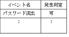
- FIG. 17 is a diagram illustrating a storage example of the determination result table 33 according to the fifth embodiment.
- “password outflow”, which is an event that cannot be observed by the system, is considered to have occurred according to the estimation result of the estimation unit 26, and the occurrence determination is determined to be “OK”.
- the determination unit 25 verifies whether or not the attack event input from the alert interpretation unit 3 can be added to the event sequence registered in the event sequence storage unit 7, and is not observed if it cannot be added to the event sequence. Determine that event estimation is required. If it is determined that an unobserved event needs to be estimated, the estimation unit 26 performs estimation. When it is determined that the input attack event can be added to the existing event sequence in the event sequence storage unit 7 or is a new event sequence, the determination result is added to the determination result table 33. Later, the input attack event is input to the end determination unit 32 to determine the end of the attack event estimation process.
- the estimation unit 26 requests the event search unit 6 to search for an attack event that is dependent on the input attack event, and receives the search result of the event search unit 6. For each attack event of the search result, if the attack event of the search result is an attack event that cannot be observed by the system, it is determined that the attack event newly obtained by the search is observed. Each attack event regarded as observed is input to the determination unit 25, and the input attack event can be added to the existing event sequence in the event sequence storage unit 7, or a new event The estimation is performed recursively until it is determined to be a sequence.
- the generation unit 28 calls an attack event depending on the input attack event from the storage unit 27 with respect to the attack event input from the end determination unit 32. Thereafter, an event sequence is generated from each called attack event. At the time of event sequence generation, an attack event determined as a new event sequence based on the determination result table 33 is regarded as an independent event sequence.
- the generation unit 28 combines event sequences including events that can be added to the event sequence registered in the event sequence storage unit 7. At this time, if a plurality of event strings registered in the event string storage unit 7 can be combined, they are combined into one event string. Attack events determined by the estimation unit 26 as not satisfying some or all of the preconditions necessary for observation are excluded from event sequence generation.
- the generation unit 28 registers / updates the generated event sequence and the event sequence combined with the event sequence registered in the event sequence storage unit 7 in the event sequence storage unit 7. .
- the generation unit 28 notifies the detection state management unit 8 that the event sequence has been updated by generating the event sequence.
- the end determination unit 32 first stores the attack event input from the alert interpretation unit 3 as an initial event. Thereafter, when a new attack event is input, it is compared with the initial event. When the same event as the initial event is input, the initial event is input to the generation unit 28.
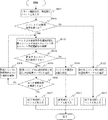
- FIG. 18 is a flowchart illustrating a process flow of the determination unit 25 according to the fifth embodiment.
- steps S901 to S904 is the same as the processing of steps S201 to S204 of the determination unit 25 in the first embodiment shown in FIG.
- step S905 the determination unit 25 determines that the input event X can be added to the existing event sequence, and adds it to the determination result table 33. Is done.
- step S906 when there are a plurality of preconditions, it is confirmed whether or not all the preconditions have been determined. If all the preconditions have been determined, the process proceeds to step S907 due to a Yes branch, the event X is input to the end determination unit 32, and the process ends.
- step S906 If all the preconditions have not been determined in step S906, the process proceeds to step S908 by branching No, and the determination is made for the preconditions that have not been determined, and the process returns to step S903 and the determination is performed again. Continue processing.
- step S904 If there is no corresponding event sequence in step S904, the determination unit 25 determines in step S909 that event estimation is necessary, and the event X is input to the estimation unit 26 in step S910. The process ends.
- step S911 the determination unit 25 determines that the input event X is a new event sequence, and ends in step S912. The event X is input to the determination unit 32, and the process ends.
- FIG. 19 is a flowchart showing a process flow of the end determination unit 32 according to the fifth embodiment.
- step S1001 the alert interpretation unit 3 inputs an initial event X to the end determination unit 32.
- step S1002 and step S1003 the end determination unit 32 waits for an event input from the determination unit 25 or the estimation unit 26. If no event has been input in step S1003, the process returns to step S1002 due to a No branch, and again enters an event input wait state. When an event is input in step S1003, the process proceeds to step S1004 due to a Yes branch.
- step S1004 the end determination unit 32 determines whether or not the input event is equal to the initial event X. If the input event is equal to the initial event X, the process proceeds to step S1005 due to a Yes branch.
- step S1005 the end determination unit 32 inputs the initial event X to the generation unit 25, and the process ends.
- step S1003 If the input event is different from the initial event X in step S1003, the process waits for input in step S1002.
- the above is the process flow of the end determination unit 32.
- FIG. 20 is a flowchart showing a process flow of the estimation unit 26 according to the fifth embodiment.
- step S1101 the determination unit 25 inputs an event X to the estimation unit 26.
- step S1102 the estimation unit 26 requests the event search unit 6 to search for an event having the precondition of the event X in the achieved state, and searches the event database 5.
- step S1103 the estimation unit 26 determines whether there is an event corresponding to the search request. If there is an event corresponding to the search request, the process proceeds to step S1104 by branching Yes. If there is no event corresponding to the search request, the process proceeds to step S1111 by branching No.
- step S1103 when there is no event corresponding to the search request in step S1103, the estimation unit 26 determines in step S1111 that the input event X is a new event sequence, and adds it to the determination result table 33. To do. Thereafter, the process of step S1112 is performed.
- step S1103 If there is an event corresponding to the search request in step S1103, the estimation unit 26 obtains one or more corresponding events (X′_1, X′_2,%) In step S1104. Thereafter, in step S1105, a variable i for the iterative process is initialized to 1.
- step S1106 when X′_i is an event that cannot be observed by the system, the estimating unit 26 proceeds to step S1107 due to a Yes branch. If X′_i is not an event that cannot be observed by the system, the process proceeds to step S1109 by branching No.
- step S1107 the estimation unit 26 determines that the event X′_i has been observed, and further inputs the event X′_i to the determination unit 25 in step S1108.
- step S1109 the process of step S1109 is performed.
- step S1109 the estimation unit 26 determines whether all the events X′_i obtained in step S1104 have been determined. If all the events X′_i have been determined, step S1112 is performed according to a Yes branch. Proceed to If all the events X′_i have not been determined, the process proceeds to step S1110 by branching No, the variable i for the iterative process is incremented and updated, and the process returns to step S1106.
- step S1112 the estimation unit 26 confirms whether the input event X satisfies all the preconditions for observation. If all the preconditions are satisfied, the estimation unit 26 performs the step by branching Yes. The process proceeds to S1114. If some or all of the preconditions are not satisfied, the process proceeds to step S1113 by branching No.
- step S1113 the estimation unit 26 determines that the input event X has not been observed, and adds the event X to the determination result table 33. At this time, priority is given to the determination result of step S1113 even if it is considered that it was observed by step S1107.
- step S1114 the estimation unit 26 stores the input event X in the storage unit 27, and thereafter, in step S1115, the event X is input to the end determination unit 32.
- FIG. 21 is a flowchart illustrating a process flow of the generation unit 28 according to the fifth embodiment.
- step S1201 the end determination unit 32 inputs the event X to the generation unit 28.
- step S1202 the generation unit 28 calls an event having a dependency relationship with the event X from the storage unit 27.
- the dependency relationship is determined by the event precondition stored in the storage unit 27 and the achievement state relationship.
- step S1203 the generation unit 28 generates an event sequence from the preconditions and achievement states of each event called from the storage unit 27.
- step S1204 the generation unit 28 performs the following processing on the event sequence generated in step S1203 based on the determination result table 33.
- an event determined to be able to be combined with an existing event sequence registered in the event sequence storage unit 7 is combined with the event sequence.
- a plurality of event sequences registered in the event sequence storage unit 7 are combined, they are updated as one event sequence.
- An event sequence that cannot be combined with an existing event sequence is regarded as a new event sequence. If the estimation unit 26 determines that no event has been observed, the event is excluded from event sequence generation.
- step S ⁇ b> 1205 the generation unit 28 registers / updates in the event sequence storage unit 7 the generated new event sequence or the event sequence combined with the event sequence registered in the event sequence storage unit 7. .
- step S1206 the generation unit 28 notifies the detection state management unit 8 that the event sequence storage unit 7 has been updated by generating an event sequence, and the process ends.
- the invention of the fifth embodiment makes it possible to estimate an event occurrence and generate an event sequence even when the event sequence is generated by a plurality of preconditions. As a result, an attack event that cannot be observed can be estimated even for an attack event having a complicated precondition, and the versatility of the first to fourth embodiments of the present invention can be improved.
- Embodiment 6 FIG.
- an event sequence is generated by using a pre-condition of an observed attack event and searching for events that have occurred in the past.
- the attack event that is expected to be observed next from the result of the observed attack event is stored, and whether or not the newly observed attack event can be added to the existing event sequence.
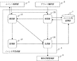
- FIG. 22 is a configuration diagram illustrating a configuration example of the attack detection apparatus 1 according to the sixth embodiment.
- the attack detection apparatus 1 includes an observation expected event storage unit 34 that stores an attack event that can be added to any of the event sequences stored in the event sequence storage unit 7 in addition to the configuration of FIG. 1. .
- FIG. 23 is a configuration diagram illustrating a configuration example of the event string generation unit 4 according to the sixth embodiment.
- the attack event input from the alert interpretation unit 3 is input to the determination unit 25.
- the determination unit 25 searches the observation expected event storage unit 34 to check whether the input attack event is included, and determines whether the event can be added to the event string.
- the estimation unit 26 searches the event database 5 for an attack event having the input event achievement state as a precondition from the event database 5 and stores it in the observation expected event storage unit 34. In addition, when the result of the search by the event search unit 6 is an event that cannot be observed by the system, the estimation unit 26 estimates an event that cannot be observed by the system. The estimation method will be described later.
- the generation unit 28 adds the attack event in the storage unit 27 and the input attack event to the event sequence obtained by the determination unit 25, and updates the event sequence storage unit 7. Alternatively, the generation unit 28 newly registers an event sequence in the event sequence storage unit 7.
- FIG. 24 is a flowchart illustrating a process flow of the attack detection apparatus according to the sixth embodiment.
- step S 1305 the alert interpretation unit 3 inputs an attack event to the event sequence generation unit 4.
- step S1306 the event sequence generation unit 4 searches the observation expected event storage unit 34, and in step S1307, as a result of the search, determines whether the input attack event can be added to the existing event sequence. . In this determination, when the input attack event is included in the search result, it is determined that the input attack event can be added to the existing event string. This determination result is used in later step S1311.
- step S1308 the event string generation unit 4 requests the event search unit 6 to search for an event having the input attack event achievement state as a precondition.
- step S1309 the event search unit 6 searches the event database 5 and returns attack event definition information corresponding to the search request.
- step S1310 the event string generation unit 4 registers attack event definition information corresponding to the search request in the observation expected event storage unit 34.
- step S1311 the event sequence generation unit 4 refers to the determination result in step S1307. If it is determined that the input attack event can be added to the existing event sequence, the branch of Yes causes step S1312. Proceed to If it is determined that it cannot be added, the process proceeds to step S1313 due to a No branch.
- step S1312 the event sequence generation unit 4 adds an attack event to the event sequence corresponding to the attack event in the corresponding observation expected event storage unit 34.
- the event string storage unit 7 is updated.
- step S1313 the event string generation unit 4 registers the input attack event as a new event string in the event string storage unit 7. Then, the process of step S1314 and step S1315 is performed.
- FIG. 25 is a flowchart illustrating a process flow of the determination unit 25 according to the sixth embodiment.
- step S1401 the alert interpretation unit 3 inputs an event X to the determination unit 25.
- step S1402 the determination unit 25 searches the observation expected event storage unit 34 to check whether the event X exists.
- step S1403 the determination unit 25 determines whether or not the event X exists as a result of the search. If the event X exists, the process proceeds to step S1404 due to a Yes branch. If the event X does not exist, the process proceeds to step S1406 due to a No branch.
- step S1404 the determination unit 25 determines that the input event X can be added to the existing event sequence.
- step S ⁇ b> 1405 the determination unit 25 takes over the event string information corresponding to the event X stored in the observation expected event storage unit 34 to the event X and deletes it from the observation expected event storage unit 34.
- step S1407 the determination unit 25 inputs the event X to the estimation unit 26, and the process ends.
- step S1403 determines in step S1406 that the event X is a new event sequence. Thereafter, through the process of step S1407, the determination unit 25 inputs the event X to the estimation unit 26, and the process ends.
- FIG. 26 is a flowchart showing a process flow of the estimation unit 26 according to the sixth embodiment.
- step S1501 the determination unit 25 inputs an event X to the estimation unit 26.
- step S1502 the estimation unit 26 determines whether or not the event X has an achievement state. If the event X has an achievement state, the process proceeds to step S1503 due to a Yes branch. If there is no achievement state, the process proceeds to step S1513 by branching No.
- step S1503 the estimation unit 26 requests the event search unit 6 to search for an event having the achievement state of the event X as a precondition, and searches the event database 5.
- step S1504 the estimation unit 26 determines whether or not there is an event corresponding to the search request. If there is an event corresponding to the search request, the process proceeds to step S1505 by branching Yes. If there is no event corresponding to the search request, the process proceeds to step S1513 by branching No.
- step S ⁇ b> 1505 the estimation unit 26 obtains the event X ′ corresponding to the search request from the event search unit 6.
- step S1506 the estimation unit 26 confirms whether or not the event X ′ is an event that cannot be observed from the setting of whether or not observation is possible. If the event X ′ is an event that cannot be observed, the process proceeds to step S1507 due to a Yes branch. If the event is observable, the process proceeds to step S1511 due to a No branch.
- step S1507 the estimation unit 26 determines that the event X ′ has already been observed.
- step S1508 the estimation unit 26 takes over the event string information corresponding to the event X as the event X ′. Thereafter, the event X is stored in the storage unit 27 in step S1509, the event X ′ is newly set as the event X in step S1510, and the process returns to step S1502.
- step S1506 the estimation unit 26 takes over event sequence information corresponding to the event X in event X ′.
- step S 1512 the estimation unit 26 adds the event X ′ to the observation expected event storage unit 34 and updates the observation expected event storage unit 34. Thereafter, in step S1513, the estimation unit 26 inputs the event X to the generation unit 28, and the process ends.
- step S1502 If the event X does not have an achievement state in step S1502, or if the corresponding event does not exist as a result of the search in step S1504, the estimation unit 26 generates the generation unit 28 in step S1513. Event X is input to, and the process ends.
- FIG. 27 is a flowchart illustrating a process flow of the generation unit 28 according to the sixth embodiment.
- step S1601 the estimation unit 26 inputs an event X to the generation unit 28.
- step S1602 the generation unit 28 calls an event having a dependency relationship with the event X from the storage unit 27.
- the dependency relationship is determined by the event precondition stored in the storage unit 27 and the achievement state relationship.
- step S1603 the generation unit 28 confirms whether the input event X is determined as a new event sequence by the determination unit 25. If it is determined as a new event sequence, the generation unit 28 performs a step by branching Yes. The process proceeds to S1604. If it is determined that the event sequence is not a new event sequence, the process advances to step S1605 by branching No.
- step S1604 the generation unit 28 generates an event sequence from the preconditions and achievement states of each event called from the storage unit 27, and registers the event sequence in the event sequence storage unit 7 as a new event sequence.
- step S1609 the generation unit 28 notifies the detection state management unit 8 that the event string storage unit 7 has been updated, and the process ends.
- step S1603 If it is determined in step S1603 that the event sequence is not a new event sequence, the generation unit 28 determines in step S1605 whether the input event X has been determined by the determination unit 25 to be added to the existing event sequence. If it is determined that it can be added, the process proceeds to step S1606 due to a Yes branch. If it is determined that addition is not possible, the process ends due to a No branch.
- step S1606 the generation unit 28 calls an event sequence from the event sequence storage unit 7 based on the event sequence information corresponding to the input event X.
- step S1607 the generation unit 28 generates an event sequence from the preconditions and achievement states of each event called from the storage unit 27, and adds the event sequence to the event sequence called from the event sequence storage unit 7.
- step S1608 the generation unit 28 updates the event sequence before the addition in the event sequence storage unit 7 with the event sequence after the addition, performs the processing in step S1609, and ends the processing.
- the invention of the sixth embodiment stores the attack event that is expected to be observed next from the achievement state of the observed attack event, so that the newly observed attack event is Judge whether it can be added to the existing event sequence.
- the determination of whether or not the event string can be added only needs to examine the stored attack events that are expected to be observed. Compared with the first to fifth embodiments that need to be searched for each event string. Thus, the determination can be made more efficiently.
- 1 attack detection device 2 alert reception unit, 3 alert interpretation unit, 4 event sequence generation unit, 5 event database, 6 event search unit, 7 event sequence storage unit, 8 detection status management unit, 9 attack event definition information, 10 advance Conditions, 11 events, 12 achievement status, 13 attack accuracy, 14 observability, 15 preconditions (specific example), 16 event source, 17 event type, 18 event parameters, 19 event source (specific example), 20 event type (Specific example), 21 event parameter (specific example), 22 achievement state (specific example), 23 attack accuracy (specific example), 24 observation availability (specific example), 25 determination unit, 26 estimation unit, 27 storage unit, 28 Generation unit, 29 observation standby event storage unit, 30 chain probability storage unit, 31 detection omission Rate storage unit, 32 end determining unit, 33 determination result table, 34 observed expected event storage unit.
Abstract
Description
また、この特許文献1の手法は、イベントの検知に漏れがある場合、依存関係の判定を行なうために、各イベントの管理対象の依存関係をプロセス割当テーブルによって保持することが開示されている。このため、全てのイベントの管理対象の依存関係を保持する必要があり、管理するイベントの数の増大に従ってイベントの管理対象の依存関係が爆発的に増加してしまうという課題があった。
また、本発明は、イベントに事前条件と結果を定義することにより、発生したイベントと依存関係のあるイベントを動的に調べ、全てのイベントの管理対象の依存関係を保持することなく、システムが検知することのできないイベントの推定を行なうことにより、管理するイベントの数の増大に従ってイベントの管理対象の依存関係が爆発的に増加することを防止することを目的とする。
図1は、実施の形態1に係る攻撃検知装置の一構成例を示す構成図である。
図1において、攻撃検知装置1は、アラート受信部2、アラート解釈部3、イベント列生成部4、イベントデータベース5、イベント検索部6、イベント列記憶部7、検知状態管理部8により構成される。
図2は、実施の形態1に係る攻撃検知装置の処理の流れを示すフローチャートである。
図3は、攻撃イベント定義情報の例を示す図である。
図3の攻撃イベント定義情報9のように、攻撃イベント定義情報は、事前条件10、イベント11、達成状態12、攻撃確度13、観測可否14で構成されている。
る。
イベント発生源16は、攻撃イベント定義情報9が対象とするイベント発生源を示している。符号19は、発生源として許される値を示しており、この例では変数Hによって事前条件15と関連付けられている(「$H」の冒頭にあるドルマーク($)は、Hが変数であることを示している)。
イベント種別17は、攻撃イベント定義情報9が対象としているイベントの種別を指定している。具体的なイベント種別は、符号20のように指定される。
イベントパラメータ18は、イベントのパラメータを示す。イベントパラメータ18では、攻撃イベント定義情報9が対象とする値が指定されている。図3に示した例では、符号21でUSERという名称のパラメータが符号15で示されている変数Aと同じ値をとることが求められている。
図4は、イベントデータベース5に格納された攻撃イベント定義情報9の一例である。
図4の格納例では、攻撃イベント定義情報9に定義される情報の他、攻撃イベントを検知した際に記録される発生時刻、発生源、送信先などの情報も含まれている。発生源は、例えば、発信元IPアドレスであり、送信先は、送信先URLが記録される。なお、図4の格納例では、攻撃イベントが検知される前の状態を示しており、発生時刻、発生源、送信先は空欄になっている。
まず、イベント列生成部4の構成に関して説明する。
図5は、実施の形態1に係るイベント列生成部4の一構成例を示す構成図である。
図6は、実施の形態1に係る判定部25の処理の流れを示すフローチャートである。
図7は、実施の形態1に係る推定部26の処理の流れを示すフローチャートである。
図8は、実施の形態1に係る生成部28の処理の流れを示すフローチャートである。
以上の実施の形態1では、システムが観測することができないイベントは発生したとみなしてイベント列を生成するようにしたものであるが、実施の形態2では、あるイベントAが観測できないとき、その事前条件を満たすイベントB、及びイベントAの達成状態を事前条件に持つイベントXの両者を観測できたとき、イベントAを発生したものとみなしてイベント列を生成し、検知精度をさらに向上させる実施形態を示す。
図9において、イベント列生成部4は、判定部25、記憶部27、生成部28については、実施の形態1と同様の構成となる。以下、推定部26および観測待機イベント記憶部29について説明する。
アラート解釈部3から出力された攻撃イベントは、判定部25に入力される。判定部25の動作については、図6と同様である。判定部25に入力された攻撃イベントは、判定部25内の処理によって、推定部26または生成部28に入力される。
図10は、実施の形態2に係る推定部26の処理の流れを示すフローチャートである。
以上の実施の形態2では、直前のイベントと直後のイベントを観測できているか否かによって、システムが観測することができないイベントを発生したものとみなすようにしたが、イベント間の依存度合い(発生確率)を評価しないため、実際には観測したとは考えにくいようなイベントを観測したものとみなしてしまう可能性がある。そこで、実施の形態3では、イベント連鎖の発生確率を用いて、システムが観測することのできないイベントか否かを評価し、発生確率が閾値を越えた場合に発生したものと判定することができるような実施形態を示す。
図11において、イベント列生成部4は、図5の構成に加え、複数のイベントが連鎖する確率である連鎖確率を記憶する連鎖確率記憶部30を備えている。
アラート解釈部3から出力された攻撃イベントは、判定部25に入力される。判定部25の動作については、図6と同様である。判定部25に入力された攻撃イベントは、判定部25内の処理によって、推定部26または生成部28に入力される。
以下、図12を参照して、実施の形態3に係る推定部26の処理の流れを説明する。
以下、図13を参照して、実施の形態3に係る生成部28の処理の流れを説明する。
以上の実施の形態1~3は、システムが観測することのできない攻撃イベントに関する攻撃イベント推定の手法であるが、本実施の形態4では、システムが検知漏れによって観測することのできなかった攻撃イベントを推定し、イベント列を生成する実施形態を示す。
図14において、イベント列生成部4は、図5の構成に加え、イベントの検知漏れ率を記憶する検知漏れ率記憶部31を備えている。
アラート解釈部3から出力された攻撃イベントは、判定部25に入力される。判定部25の動作については、図6と同様である。判定部25に入力された攻撃イベントは、判定部25内の処理によって、推定部26または生成部28に入力される。
以下、図15を参照して、実施の形態4に係る推定部26の処理の流れを説明する。
以上の実施の形態1~4は、イベント列生成のために複数の事前条件が必要であるという仮定がなく、イベント列は1列となっていることを前提としていた。本実施の形態5では、複数の事前条件によってイベント列が生成される場合においてもイベント発生の推定を行ない、イベント列の生成が可能になる実施形態を示す。
図16において、イベント列生成部4は、図5の構成に加え、攻撃イベントの推定処理の終了を判定する終了判定部32、及び判定部25と推定部26による判定結果を格納する判定結果テーブル33を備えている。
図17は、実施の形態5に係る判定結果テーブル33の格納例を示す図である。
図17において、システムが観測できないイベントである「パスワード流出」が、推定部26の推定結果により、発生したものとみなされて発生判定が「可」と判定された例である。
以下、判定部25の動作について説明する。
図18は、実施の形態5に係る判定部25の処理の流れを示すフローチャートである。
図19は、実施の形態5に係る終了判定部32の処理の流れを示すフローチャートである。
以上が、、終了判定部32の処理の流れである。
図20は、実施の形態5に係る推定部26の処理の流れを示すフローチャートである。
図21は、実施の形態5に係る生成部28の処理の流れを示すフローチャートである。
以上の実施の形態1~5は、観測された攻撃イベントの事前条件を利用し、過去に発生したイベントを遡るように検索することによってイベント列の生成を行なっていた。本実施の形態6では、観測された攻撃イベントの結果から次に観測することが期待される攻撃イベントを記憶し、新たに観測された攻撃イベントが、既存のイベント列に追加可能であるかどうかをより効率良く判定することが可能になる実施形態を示す。
図22において、攻撃検知装置1は、図1の構成に加えて、イベント列記憶部7に記憶されているイベント列のいずれかに追加可能な攻撃イベントを記憶する観測期待イベント記憶部34を備える。
図23において、アラート解釈部3から入力された攻撃イベントは、判定部25に入力される。判定部25は、観測期待イベント記憶部34内を検索し、入力された攻撃イベントが含まれているかどうかを調べ、イベント列に追加可能なイベントかどうかを判定する。
図24は、実施の形態6に係る攻撃検知装置の処理の流れを示すフローチャートである。
次に、ステップS1305において、アラート解釈部3は、イベント列生成部4に攻撃イベントを入力する。
図25は、実施の形態6に係る判定部25の処理の流れを示すフローチャートである。
図26は、実施の形態6に係る推定部26の処理の流れを示すフローチャートである。
図27は、実施の形態6に係る生成部28の処理の流れを示すフローチャートである。
Claims (8)
- 情報システムに対する攻撃が行われる過程において前記情報システムで観測されるイベントと、前記イベントが観測される前の攻撃の進展段階であるイベント前段階と、前記イベントが観測された後の攻撃の進展段階であるイベント後段階とが記述されるイベント段階情報を、複数のイベントに対して記憶するイベント段階情報記憶部と、
前記情報システムで観測された観測イベントを通知する観測イベント通知情報を受信する観測イベント通知情報受信部と、
前記観測イベント通知情報で通知されている観測イベントが記述されているイベント段階情報を前記イベント段階情報記憶部から検索し、検索したイベント段階情報のイベント前段階に合致するイベント後段階または検索したイベント段階情報のイベント後段階に合致するイベント前段階が記述されているイベント段階情報を前記イベント段階情報記憶部から検索し、検索したイベント段階情報のイベントが観測できない観測不可イベントである場合、前記観測不可イベントが観測されたとみなして前記観測イベントと前記観測不可イベントとを依存関係で接続してイベント列を生成するイベント列生成部と
を備える攻撃検知装置。 - 前記イベント列生成部は、前記観測不可イベントのイベント前段階に合致するイベント後段階または前記観測不可イベントのイベント後段階に合致するイベント前段階が記述されているイベント段階情報を前記イベント段階情報記憶部から検索し、検索したイベント段階情報のイベントが観測されていた場合、前記観測不可イベントが観測されたとみなして前記観測イベントと前記観測不可イベントとを依存関係で接続してイベント列を生成する請求項1記載の攻撃検知装置。
- 複数のイベントの連鎖確率を記憶する連鎖確率記憶部を備え、
前記イベント列生成部は、前記連鎖確率記憶部に記憶された前記連鎖確率に基づいてイベント列の発生確率を算出し、この発生確率が閾値以上である場合に、前記観測不可イベントが観測されたとみなして前記観測イベントと前記観測不可イベントとを依存関係で接続してイベント列を生成する請求項1記載の攻撃検知装置。 - イベントの検知漏れ率を記憶する検知漏れ率記憶部を備え、
前記イベント列生成部は、前記検知漏れ率記憶部に記憶された前記検知漏れ率が閾値を越えた場合に、前記観測不可イベントが観測されたとみなして前記観測イベントと前記観測不可イベントとを依存関係で接続してイベント列を生成する請求項1記載の攻撃検知装置。 - 前記イベント段階情報記憶部が記憶する前記イベント段階情報に前記イベント前段階または前記イベント後段階が複数記述され、
前記イベント列生成部は、前記イベント段階情報に記述された複数の前記イベント前段階または前記イベント後段階の観測可否の判定結果に基づき、イベント列を生成する請求項1から請求項4のいずれか一項に記載の攻撃検知装置。 - 前記観測イベントのイベント後段階が合致するイベント前段階が記述されているイベント段階情報を記憶する観測期待イベント記憶部を備え、
前記イベント列生成部は、観測イベントが前記イベント前段階に記述されているイベント段階情報を前記観測期待イベント記憶部から検索してイベント列を生成する請求項1から請求項4のいずれか一項に記載の攻撃検知装置。 - 情報システムに対する攻撃を検知する攻撃検知装置の攻撃検知方法であって、
イベント段階情報記憶部が、前記情報システムに対する攻撃が行われる過程において前記情報システムで観測されるイベントと、前記イベントが観測される前の攻撃の進展段階であるイベント前段階と、前記イベントが観測された後の攻撃の進展段階であるイベント後段階とが記述されるイベント段階情報を、複数のイベントに対して記憶するイベント段階情報記憶ステップと、
観測イベント通知情報受信部が、前記情報システムで観測された観測イベントを通知する観測イベント通知情報を受信するステップと、
イベント列生成部が、前記観測イベント通知情報で通知されている観測イベントが記述されているイベント段階情報を前記イベント段階情報記憶部から検索し、検索したイベント段階情報のイベント前段階に合致するイベント後段階または検索したイベント段階情報のイベント後段階に合致するイベント前段階が記述されているイベント段階情報を前記イベント段階情報記憶部から検索し、検索したイベント段階情報のイベントが観測できない観測不可イベントである場合、前記観測不可イベントが観測されたとみなして前記観測イベントと前記観測不可イベントとを依存関係で接続してイベント列を生成するイベント列生成ステップと
を備える攻撃検知方法。 - 情報システムに対する攻撃が行われる過程において前記情報システムで観測されるイベントと、前記イベントが観測される前の攻撃の進展段階であるイベント前段階と、前記イベントが観測された後の攻撃の進展段階であるイベント後段階とが記述されるイベント段階情報を、複数のイベントに対して記憶するコンピュータに、
前記情報システムで観測された観測イベントを通知する観測イベント通知情報を受信する観測イベント通知情報受信処理と、
前記観測イベント通知情報で通知されている観測イベントが記述されているイベント段階情報を検索し、検索したイベント段階情報のイベント前段階に合致するイベント後段階または検索したイベント段階情報のイベント後段階に合致するイベント前段階が記述されているイベント段階情報を検索し、検索したイベント段階情報のイベントが観測できない観測不可イベントである場合、前記観測不可イベントが観測されたとみなして前記観測イベントと前記観測不可イベントとを依存関係で接続してイベント列を生成するイベント列生成処理とを実行させる攻撃検知プログラム。
Priority Applications (5)
| Application Number | Priority Date | Filing Date | Title |
|---|---|---|---|
| CN201480076371.6A CN106062765B (zh) | 2014-02-26 | 2014-02-26 | 攻击检测装置和攻击检测方法 |
| JP2016504857A JP6000495B2 (ja) | 2014-02-26 | 2014-02-26 | 攻撃検知装置、攻撃検知方法、及び攻撃検知プログラム |
| US15/121,716 US9916445B2 (en) | 2014-02-26 | 2014-02-26 | Attack detection device, attack detection method, and non-transitory computer readable recording medium recorded with attack detection program |
| EP14883911.1A EP3113061B1 (en) | 2014-02-26 | 2014-02-26 | Attack detection device, attack detection method, and attack detection program |
| PCT/JP2014/001000 WO2015128896A1 (ja) | 2014-02-26 | 2014-02-26 | 攻撃検知装置、攻撃検知方法、及び攻撃検知プログラム |
Applications Claiming Priority (1)
| Application Number | Priority Date | Filing Date | Title |
|---|---|---|---|
| PCT/JP2014/001000 WO2015128896A1 (ja) | 2014-02-26 | 2014-02-26 | 攻撃検知装置、攻撃検知方法、及び攻撃検知プログラム |
Publications (1)
| Publication Number | Publication Date |
|---|---|
| WO2015128896A1 true WO2015128896A1 (ja) | 2015-09-03 |
Family
ID=54008271
Family Applications (1)
| Application Number | Title | Priority Date | Filing Date |
|---|---|---|---|
| PCT/JP2014/001000 WO2015128896A1 (ja) | 2014-02-26 | 2014-02-26 | 攻撃検知装置、攻撃検知方法、及び攻撃検知プログラム |
Country Status (5)
| Country | Link |
|---|---|
| US (1) | US9916445B2 (ja) |
| EP (1) | EP3113061B1 (ja) |
| JP (1) | JP6000495B2 (ja) |
| CN (1) | CN106062765B (ja) |
| WO (1) | WO2015128896A1 (ja) |
Cited By (3)
| Publication number | Priority date | Publication date | Assignee | Title |
|---|---|---|---|---|
| EP3264312A1 (en) * | 2016-07-01 | 2018-01-03 | EntIT Software LLC | Model-based computer attack analytics orchestration |
| WO2019058489A1 (ja) * | 2017-09-21 | 2019-03-28 | 三菱電機株式会社 | アラート頻度制御装置およびアラート頻度制御プログラム |
| CN113793227A (zh) * | 2021-09-16 | 2021-12-14 | 中国电子科技集团公司第二十八研究所 | 一种用于社交网络事件的类人智能感知与预测方法 |
Families Citing this family (10)
| Publication number | Priority date | Publication date | Assignee | Title |
|---|---|---|---|---|
| DE102014213752A1 (de) * | 2014-07-15 | 2016-01-21 | Siemens Aktiengesellschaft | Rechenvorrichtung und Verfahren zum Erkennen von Angriffen auf ein technisches System anhand von Ereignissen einer Ereignisfolge |
| WO2016014021A1 (en) * | 2014-07-21 | 2016-01-28 | Hewlett-Packard Development Company, L.P. | Security indicator linkage determination |
| WO2016075825A1 (ja) * | 2014-11-14 | 2016-05-19 | 三菱電機株式会社 | 情報処理装置及び情報処理方法及びプログラム |
| US10104100B1 (en) * | 2016-03-03 | 2018-10-16 | Symantec Corporation | Systems and methods for detecting anomalies that are potentially indicative of malicious attacks |
| CN108875364B (zh) * | 2017-12-29 | 2020-06-26 | 北京安天网络安全技术有限公司 | 未知文件的威胁性判定方法、装置、电子设备及存储介质 |
| JP6847326B2 (ja) * | 2018-11-01 | 2021-03-24 | 三菱電機株式会社 | 情報処理装置、情報処理方法及び情報処理プログラム |
| WO2020105156A1 (ja) * | 2018-11-21 | 2020-05-28 | 三菱電機株式会社 | シナリオ生成装置、シナリオ生成方法およびシナリオ生成プログラム |
| US11055408B2 (en) * | 2018-11-30 | 2021-07-06 | International Business Machines Corporation | Endpoint detection and response attack process tree auto-play |
| CN113544676A (zh) | 2019-03-12 | 2021-10-22 | 三菱电机株式会社 | 攻击估计装置、攻击控制方法和攻击估计程序 |
| WO2021156966A1 (ja) * | 2020-02-05 | 2021-08-12 | 日本電気株式会社 | 分析システム、方法およびプログラム |
Citations (1)
| Publication number | Priority date | Publication date | Assignee | Title |
|---|---|---|---|---|
| US20040093510A1 (en) * | 2002-11-07 | 2004-05-13 | Kari Nurmela | Event sequence detection |
Family Cites Families (34)
| Publication number | Priority date | Publication date | Assignee | Title |
|---|---|---|---|---|
| US7203962B1 (en) * | 1999-08-30 | 2007-04-10 | Symantec Corporation | System and method for using timestamps to detect attacks |
| US7032114B1 (en) * | 2000-08-30 | 2006-04-18 | Symantec Corporation | System and method for using signatures to detect computer intrusions |
| BR0102542B1 (pt) * | 2001-04-04 | 2009-01-13 | método e sistema de captura e armazenamento de uma seqüência de imagens associadas a uma ou mais infrações de tránsito . | |
| JP2004535018A (ja) | 2001-07-06 | 2004-11-18 | コンピュータ アソシエイツ シンク,インコーポレイテッド | システム及び企業事象の根本原因を相関付けし判定するための方法とシステム |
| FR2852754B1 (fr) * | 2003-03-20 | 2005-07-08 | At & T Corp | Systeme et methode de protection d'un reseau de transmission ip contre les attaques de deni de service |
| JP3999188B2 (ja) | 2003-10-28 | 2007-10-31 | 富士通株式会社 | 不正アクセス検知装置、不正アクセス検知方法および不正アクセス検知プログラム |
| JP4060263B2 (ja) | 2003-11-18 | 2008-03-12 | Kddi株式会社 | ログ分析装置およびログ分析プログラム |
| JP2005198031A (ja) | 2004-01-07 | 2005-07-21 | Mitsubishi Electric Corp | ソフトウェア無線機 |
| JP4500921B2 (ja) | 2004-01-09 | 2010-07-14 | Kddi株式会社 | ログ分析装置、ログ分析方法およびログ分析プログラム |
| JP2005244429A (ja) | 2004-02-25 | 2005-09-08 | Intelligent Cosmos Research Institute | ネットワーク異常検出の特徴量抽出方法、その方法をコンピュータに実行させるプログラム、その特徴量抽出装置およびネットワーク異常検出システム |
| JP4624181B2 (ja) | 2004-07-28 | 2011-02-02 | 株式会社エヌ・ティ・ティ・データ | 不正アクセス対策制御装置および不正アクセス対策制御プログラム |
| JP4170299B2 (ja) | 2005-01-31 | 2008-10-22 | 独立行政法人 宇宙航空研究開発機構 | 通信状態遷移モニタ方法及びこれを利用した通信状態遷移モニタ装置 |
| US7716739B1 (en) * | 2005-07-20 | 2010-05-11 | Symantec Corporation | Subjective and statistical event tracking incident management system |
| JP2007242002A (ja) | 2006-02-10 | 2007-09-20 | Mitsubishi Electric Corp | ネットワーク管理装置及びネットワーク管理方法及びプログラム |
| JP4773332B2 (ja) | 2006-12-28 | 2011-09-14 | 三菱電機株式会社 | セキュリティ管理装置及びセキュリティ管理方法及びプログラム |
| US8051204B2 (en) * | 2007-04-05 | 2011-11-01 | Hitachi, Ltd. | Information asset management system, log analysis server, log analysis program, and portable medium |
| EP2040435B1 (en) | 2007-09-19 | 2013-11-06 | Alcatel Lucent | Intrusion detection method and system |
| JP5237034B2 (ja) | 2008-09-30 | 2013-07-17 | 株式会社日立製作所 | イベント情報取得外のit装置を対象とする根本原因解析方法、装置、プログラム。 |
| FR2936914B1 (fr) | 2008-10-02 | 2011-10-14 | Valeo Equip Electr Moteur | Dispositif de redressement de courant pour machine electrique tournante et machine electrique tournante comportant un tel dispositif. |
| JP5066544B2 (ja) | 2009-03-31 | 2012-11-07 | 株式会社富士通ソーシアルサイエンスラボラトリ | インシデント監視装置,方法,プログラム |
| JP2010250607A (ja) | 2009-04-16 | 2010-11-04 | Hitachi Ltd | 不正アクセス解析システム、不正アクセス解析方法、および不正アクセス解析プログラム |
| CN101599958A (zh) * | 2009-07-02 | 2009-12-09 | 西安电子科技大学 | 基于场景的关联引擎系统及其数据处理方法 |
| US8595176B2 (en) * | 2009-12-16 | 2013-11-26 | The Boeing Company | System and method for network security event modeling and prediction |
| US20110270957A1 (en) * | 2010-04-30 | 2011-11-03 | The Phan | Method and system for logging trace events of a network device |
| JP5685922B2 (ja) | 2010-12-17 | 2015-03-18 | 富士通株式会社 | 管理装置、管理プログラム、および管理方法 |
| US8904531B1 (en) * | 2011-06-30 | 2014-12-02 | Emc Corporation | Detecting advanced persistent threats |
| US8743200B2 (en) * | 2012-01-16 | 2014-06-03 | Hipass Design Llc | Activity monitor |
| WO2013114830A1 (ja) | 2012-02-02 | 2013-08-08 | 日本電気株式会社 | プロセス予測実行装置及びプロセス予測実行方法 |
| US20130325787A1 (en) * | 2012-06-04 | 2013-12-05 | Intelligent Software Solutions, Inc. | Temporal Predictive Analytics |
| US8930964B2 (en) * | 2012-07-31 | 2015-01-06 | Hewlett-Packard Development Company, L.P. | Automatic event correlation in computing environments |
| JP6047017B2 (ja) * | 2013-01-11 | 2016-12-21 | キヤノン株式会社 | パターン抽出装置および制御方法 |
| JP5972401B2 (ja) * | 2013-01-21 | 2016-08-17 | 三菱電機株式会社 | 攻撃分析システム及び連携装置及び攻撃分析連携方法及びプログラム |
| US20160164893A1 (en) * | 2013-07-17 | 2016-06-09 | Hewlett-Packard Development Company, L.P. | Event management systems |
| WO2015059791A1 (ja) * | 2013-10-24 | 2015-04-30 | 三菱電機株式会社 | 情報処理装置及び情報処理方法及びプログラム |
-
2014
- 2014-02-26 EP EP14883911.1A patent/EP3113061B1/en not_active Not-in-force
- 2014-02-26 WO PCT/JP2014/001000 patent/WO2015128896A1/ja active Application Filing
- 2014-02-26 US US15/121,716 patent/US9916445B2/en not_active Expired - Fee Related
- 2014-02-26 JP JP2016504857A patent/JP6000495B2/ja active Active
- 2014-02-26 CN CN201480076371.6A patent/CN106062765B/zh not_active Expired - Fee Related
Patent Citations (1)
| Publication number | Priority date | Publication date | Assignee | Title |
|---|---|---|---|---|
| US20040093510A1 (en) * | 2002-11-07 | 2004-05-13 | Kari Nurmela | Event sequence detection |
Non-Patent Citations (2)
| Title |
|---|
| KIYOTO KAWAUCHI: "A Vulnerability Assessment Tool Using First-Order Predicate Logic", IPSJ SIG NOTES, vol. 2002, no. 122, 20 December 2002 (2002-12-20), pages 43 - 48, XP055358910 * |
| See also references of EP3113061A4 * |
Cited By (6)
| Publication number | Priority date | Publication date | Assignee | Title |
|---|---|---|---|---|
| EP3264312A1 (en) * | 2016-07-01 | 2018-01-03 | EntIT Software LLC | Model-based computer attack analytics orchestration |
| US10262132B2 (en) | 2016-07-01 | 2019-04-16 | Entit Software Llc | Model-based computer attack analytics orchestration |
| WO2019058489A1 (ja) * | 2017-09-21 | 2019-03-28 | 三菱電機株式会社 | アラート頻度制御装置およびアラート頻度制御プログラム |
| JPWO2019058489A1 (ja) * | 2017-09-21 | 2019-12-26 | 三菱電機株式会社 | アラート頻度制御装置およびアラート頻度制御プログラム |
| CN113793227A (zh) * | 2021-09-16 | 2021-12-14 | 中国电子科技集团公司第二十八研究所 | 一种用于社交网络事件的类人智能感知与预测方法 |
| CN113793227B (zh) * | 2021-09-16 | 2023-10-31 | 中国电子科技集团公司第二十八研究所 | 一种用于社交网络事件的类人智能感知与预测方法 |
Also Published As
| Publication number | Publication date |
|---|---|
| EP3113061A4 (en) | 2017-09-27 |
| CN106062765A (zh) | 2016-10-26 |
| US9916445B2 (en) | 2018-03-13 |
| JPWO2015128896A1 (ja) | 2017-03-30 |
| EP3113061B1 (en) | 2018-11-28 |
| EP3113061A1 (en) | 2017-01-04 |
| CN106062765B (zh) | 2017-09-22 |
| JP6000495B2 (ja) | 2016-09-28 |
| US20160378980A1 (en) | 2016-12-29 |
Similar Documents
| Publication | Publication Date | Title |
|---|---|---|
| JP6000495B2 (ja) | 攻撃検知装置、攻撃検知方法、及び攻撃検知プログラム | |
| JP6239215B2 (ja) | 情報処理装置、情報処理方法及び情報処理プログラム | |
| JP6053948B2 (ja) | 情報処理装置及び情報処理方法及びプログラム | |
| US20150026244A1 (en) | Communication system, client terminal, and server device | |
| JP2019057139A (ja) | 運用管理システム、監視サーバ、方法およびプログラム | |
| KR20210002594A (ko) | 데이터 처리 장치 및 데이터 처리 방법 | |
| JP5711675B2 (ja) | ネットワーク異常検出装置およびネットワーク異常検出方法 | |
| US11405411B2 (en) | Extraction apparatus, extraction method, computer readable medium | |
| KR102115734B1 (ko) | 공격ㆍ이상 검지 장치, 공격ㆍ이상 검지 방법, 및 공격ㆍ이상 검지 프로그램 | |
| JP6263487B2 (ja) | プロセス抽出装置、プロセス抽出方法、及びプログラム | |
| CN110489611B (zh) | 一种智能的线索分析方法及系统 | |
| CN113810351A (zh) | 网络攻击的攻击者确定方法及装置和计算机可读存储介质 | |
| CN113452700A (zh) | 处理安全信息的方法、装置、设备以及存储介质 | |
| JP5751396B2 (ja) | 周期性検出方法、周期性検出装置および周期性検出プログラム | |
| JP6513001B2 (ja) | 故障検知装置、故障検知方法、及びプログラム | |
| KR101541307B1 (ko) | 보안 위험 예측 방법, 이를 수행하는 예측 서버 및 이를 저장하는 기록매체 | |
| JP5228498B2 (ja) | 検索方法 | |
| US10348743B2 (en) | Identification method and information processing device | |
| JP6378655B2 (ja) | 監視装置および監視方法 | |
| WO2014097699A1 (ja) | 情報処理システム、情報処理方法及びプログラム | |
| JP2023062386A (ja) | 異常検知システム及び方法 | |
| EP4030324A1 (en) | Level estimation device, level estimation method, and level estimation program | |
| Dahbi et al. | A Hidden Markov Model security scheme for query state inference in discovery services | |
| JP2017182601A (ja) | 監視装置、監視システム及び監視プログラム | |
| JP2012048294A (ja) | コンテキスト算出システム、コンテキスト算出方法、および記録媒体 |
Legal Events
| Date | Code | Title | Description |
|---|---|---|---|
| 121 | Ep: the epo has been informed by wipo that ep was designated in this application |
Ref document number: 14883911 Country of ref document: EP Kind code of ref document: A1 |
|
| ENP | Entry into the national phase |
Ref document number: 2016504857 Country of ref document: JP Kind code of ref document: A |
|
| REEP | Request for entry into the european phase |
Ref document number: 2014883911 Country of ref document: EP |
|
| WWE | Wipo information: entry into national phase |
Ref document number: 2014883911 Country of ref document: EP |
|
| WWE | Wipo information: entry into national phase |
Ref document number: 15121716 Country of ref document: US |
|
| NENP | Non-entry into the national phase |
Ref country code: DE |