WO2015122110A1 - Scroll compressor - Google Patents
Scroll compressor Download PDFInfo
- Publication number
- WO2015122110A1 WO2015122110A1 PCT/JP2015/000011 JP2015000011W WO2015122110A1 WO 2015122110 A1 WO2015122110 A1 WO 2015122110A1 JP 2015000011 W JP2015000011 W JP 2015000011W WO 2015122110 A1 WO2015122110 A1 WO 2015122110A1
- Authority
- WO
- WIPO (PCT)
- Prior art keywords
- scroll
- cooling fin
- cooling fins
- scroll compressor
- central portion
- Prior art date
Links
Images
Classifications
-
- F—MECHANICAL ENGINEERING; LIGHTING; HEATING; WEAPONS; BLASTING
- F04—POSITIVE - DISPLACEMENT MACHINES FOR LIQUIDS; PUMPS FOR LIQUIDS OR ELASTIC FLUIDS
- F04C—ROTARY-PISTON, OR OSCILLATING-PISTON, POSITIVE-DISPLACEMENT MACHINES FOR LIQUIDS; ROTARY-PISTON, OR OSCILLATING-PISTON, POSITIVE-DISPLACEMENT PUMPS
- F04C29/00—Component parts, details or accessories of pumps or pumping installations, not provided for in groups F04C18/00 - F04C28/00
- F04C29/04—Heating; Cooling; Heat insulation
-
- F—MECHANICAL ENGINEERING; LIGHTING; HEATING; WEAPONS; BLASTING
- F04—POSITIVE - DISPLACEMENT MACHINES FOR LIQUIDS; PUMPS FOR LIQUIDS OR ELASTIC FLUIDS
- F04C—ROTARY-PISTON, OR OSCILLATING-PISTON, POSITIVE-DISPLACEMENT MACHINES FOR LIQUIDS; ROTARY-PISTON, OR OSCILLATING-PISTON, POSITIVE-DISPLACEMENT PUMPS
- F04C18/00—Rotary-piston pumps specially adapted for elastic fluids
- F04C18/02—Rotary-piston pumps specially adapted for elastic fluids of arcuate-engagement type, i.e. with circular translatory movement of co-operating members, each member having the same number of teeth or tooth-equivalents
- F04C18/0207—Rotary-piston pumps specially adapted for elastic fluids of arcuate-engagement type, i.e. with circular translatory movement of co-operating members, each member having the same number of teeth or tooth-equivalents both members having co-operating elements in spiral form
- F04C18/0215—Rotary-piston pumps specially adapted for elastic fluids of arcuate-engagement type, i.e. with circular translatory movement of co-operating members, each member having the same number of teeth or tooth-equivalents both members having co-operating elements in spiral form where only one member is moving
-
- F—MECHANICAL ENGINEERING; LIGHTING; HEATING; WEAPONS; BLASTING
- F04—POSITIVE - DISPLACEMENT MACHINES FOR LIQUIDS; PUMPS FOR LIQUIDS OR ELASTIC FLUIDS
- F04C—ROTARY-PISTON, OR OSCILLATING-PISTON, POSITIVE-DISPLACEMENT MACHINES FOR LIQUIDS; ROTARY-PISTON, OR OSCILLATING-PISTON, POSITIVE-DISPLACEMENT PUMPS
- F04C18/00—Rotary-piston pumps specially adapted for elastic fluids
- F04C18/02—Rotary-piston pumps specially adapted for elastic fluids of arcuate-engagement type, i.e. with circular translatory movement of co-operating members, each member having the same number of teeth or tooth-equivalents
- F04C18/0207—Rotary-piston pumps specially adapted for elastic fluids of arcuate-engagement type, i.e. with circular translatory movement of co-operating members, each member having the same number of teeth or tooth-equivalents both members having co-operating elements in spiral form
- F04C18/0246—Details concerning the involute wraps or their base, e.g. geometry
- F04C18/0253—Details concerning the base
-
- F—MECHANICAL ENGINEERING; LIGHTING; HEATING; WEAPONS; BLASTING
- F04—POSITIVE - DISPLACEMENT MACHINES FOR LIQUIDS; PUMPS FOR LIQUIDS OR ELASTIC FLUIDS
- F04C—ROTARY-PISTON, OR OSCILLATING-PISTON, POSITIVE-DISPLACEMENT MACHINES FOR LIQUIDS; ROTARY-PISTON, OR OSCILLATING-PISTON, POSITIVE-DISPLACEMENT PUMPS
- F04C18/00—Rotary-piston pumps specially adapted for elastic fluids
- F04C18/02—Rotary-piston pumps specially adapted for elastic fluids of arcuate-engagement type, i.e. with circular translatory movement of co-operating members, each member having the same number of teeth or tooth-equivalents
- F04C18/0207—Rotary-piston pumps specially adapted for elastic fluids of arcuate-engagement type, i.e. with circular translatory movement of co-operating members, each member having the same number of teeth or tooth-equivalents both members having co-operating elements in spiral form
- F04C18/0246—Details concerning the involute wraps or their base, e.g. geometry
- F04C18/0269—Details concerning the involute wraps
- F04C18/0276—Different wall heights
-
- F—MECHANICAL ENGINEERING; LIGHTING; HEATING; WEAPONS; BLASTING
- F04—POSITIVE - DISPLACEMENT MACHINES FOR LIQUIDS; PUMPS FOR LIQUIDS OR ELASTIC FLUIDS
- F04C—ROTARY-PISTON, OR OSCILLATING-PISTON, POSITIVE-DISPLACEMENT MACHINES FOR LIQUIDS; ROTARY-PISTON, OR OSCILLATING-PISTON, POSITIVE-DISPLACEMENT PUMPS
- F04C18/00—Rotary-piston pumps specially adapted for elastic fluids
- F04C18/02—Rotary-piston pumps specially adapted for elastic fluids of arcuate-engagement type, i.e. with circular translatory movement of co-operating members, each member having the same number of teeth or tooth-equivalents
- F04C18/0207—Rotary-piston pumps specially adapted for elastic fluids of arcuate-engagement type, i.e. with circular translatory movement of co-operating members, each member having the same number of teeth or tooth-equivalents both members having co-operating elements in spiral form
- F04C18/0246—Details concerning the involute wraps or their base, e.g. geometry
- F04C18/0269—Details concerning the involute wraps
- F04C18/0284—Details of the wrap tips
-
- F—MECHANICAL ENGINEERING; LIGHTING; HEATING; WEAPONS; BLASTING
- F01—MACHINES OR ENGINES IN GENERAL; ENGINE PLANTS IN GENERAL; STEAM ENGINES
- F01C—ROTARY-PISTON OR OSCILLATING-PISTON MACHINES OR ENGINES
- F01C17/00—Arrangements for drive of co-operating members, e.g. for rotary piston and casing
- F01C17/06—Arrangements for drive of co-operating members, e.g. for rotary piston and casing using cranks, universal joints or similar elements
- F01C17/066—Arrangements for drive of co-operating members, e.g. for rotary piston and casing using cranks, universal joints or similar elements with an intermediate piece sliding along perpendicular axes, e.g. Oldham coupling
-
- F—MECHANICAL ENGINEERING; LIGHTING; HEATING; WEAPONS; BLASTING
- F04—POSITIVE - DISPLACEMENT MACHINES FOR LIQUIDS; PUMPS FOR LIQUIDS OR ELASTIC FLUIDS
- F04C—ROTARY-PISTON, OR OSCILLATING-PISTON, POSITIVE-DISPLACEMENT MACHINES FOR LIQUIDS; ROTARY-PISTON, OR OSCILLATING-PISTON, POSITIVE-DISPLACEMENT PUMPS
- F04C2240/00—Components
- F04C2240/40—Electric motor
-
- F—MECHANICAL ENGINEERING; LIGHTING; HEATING; WEAPONS; BLASTING
- F04—POSITIVE - DISPLACEMENT MACHINES FOR LIQUIDS; PUMPS FOR LIQUIDS OR ELASTIC FLUIDS
- F04C—ROTARY-PISTON, OR OSCILLATING-PISTON, POSITIVE-DISPLACEMENT MACHINES FOR LIQUIDS; ROTARY-PISTON, OR OSCILLATING-PISTON, POSITIVE-DISPLACEMENT PUMPS
- F04C2240/00—Components
- F04C2240/50—Bearings
- F04C2240/52—Bearings for assemblies with supports on both sides
Definitions
- the present invention relates to the improvement of cooling fins of a scroll compressor.
- the scroll compressor includes a fixed scroll and a orbiting scroll.
- the fixed scroll and the orbiting scroll are both provided with a spiral wrap on one side of the disk-shaped end plate.
- the fixed scroll and the orbiting scroll are opposed to each other in a state where the wraps are engaged, and the orbiting scroll is revolved with respect to the stationary scroll. Then, the volume of the compression space formed between the two scrolls is reduced as the orbiting scroll turns, thereby compressing the fluid in the space.
- the scroll compressor sucks fluid to be compressed from the outer peripheral side of the scroll and gradually advances compression toward the center.
- the compressed fluid is discharged from the port provided at the central portion of the fixed scroll.
- the scroll is exposed to higher temperatures in the central portion because the fluid is at a higher temperature as the degree of compression increases. Then, an object of this invention is to provide the scroll compressor which can perform cooling of the center part of a scroll effectively.
- the scroll compressor according to the present invention which has been made for this purpose, has a compression space for compressing fluid between a fixed scroll provided with a fixed side wrap and a fixed side cooling fin provided on the front and the fixed scroll.
- a compression space for compressing fluid between a fixed scroll provided with a fixed side wrap and a fixed side cooling fin provided on the front and the fixed scroll.
- From a plurality of fixed-side cooling fin portions comprising a plurality of fins, and from a plurality of fins, and a rotating scroll having a turning-side lap portion on the front and a turning-side cooling fin portion on the back.
- the turning side cooling fin portion (one or both) is characterized in that the fins located at the radially central portion are taller than the fins located at the outer peripheral portion around the central portion.
- the fins located at the central portion are taller than the fins located at the outer peripheral portion and the heat transfer area is wider, so that the central portion of the scroll can be effectively cooled. it can.
- one or both of the stationary side cooling fin portion and the turning side cooling fin portion can be heightened stepwise or continuously toward the central portion. If the height is continuously increased, the cooling capacity corresponding to the degree of compression of the fluid can be obtained, and thus the improvement of the cooling capacity is excellent. On the other hand, if the height is gradually increased, it is easy to manufacture, including setting the height of the height.
- the stationary side cooling fin portion and the turning side cooling fin portion have their tips aligned on the same plane.
- a stationary side end plate provided with the stationary side cooling fin portion and a turning side cooling fin portion are provided.
- the thickness of (one or both) of the pivoting end plates may be thinner in the central portion than in the peripheral portion around the central portion.
- the outer peripheral portion is taller than the central portion by providing steps on the tooth tip and the root of the stationary side lap portion and the turning side lap portion. So-called 3D scroll compressors are raised.
- the fins located at the central portion are taller than the fins located at the outer peripheral portion and the heat transfer area is wider, so that the central portion of the scroll can be effectively cooled. it can.
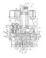
- the scroll compressor 1 As shown in FIGS. 1 and 2, the scroll compressor 1 according to the present embodiment is pivoted into a housing 10 forming an outer shell of the scroll compressor 1, a fixed scroll 20 fixed to the housing 10, and the housing 10.
- An orbiting scroll 30 which can be accommodated is provided as a main component.
- These main components are formed of metal materials such as aluminum-based alloys and iron-based alloys.
- the scroll compressor 1 can obtain a high compression ratio by adopting a three-dimensional compression mechanism that compresses fluid not only in the circumferential direction but also in the height direction, a type of scroll compression called 3D scroll (registered trademark) Machine.
- the housing 10 is a sealed container comprising a first housing 10a and a second housing 10b as shown in FIG.
- the first housing 10 a is fixed to the fixed scroll 20 and accommodates the cooling fins 24 of the fixed scroll 20 therein.
- the first housing 10 a includes a discharge port 12 that discharges the compressed fluid discharged from the discharge port 21 e of the fixed scroll 20 to the outside.
- the second housing 10 b accommodates and holds the orbiting scroll 30, the rotation preventing mechanism 40, and the drive shaft 50 inside the accommodation chamber 11 b.
- the second housing 10 b includes a storage chamber 11 c for storing the second element 45 of the rotation preventing mechanism 40 and a storage chamber 11 d for storing the drive shaft 50 and the main bearing 54 in the storage chamber 11 b.
- the fixed scroll 20 has an end plate 21 formed in a substantially disc shape, a spiral wrap 22 provided on one surface side of the end plate 21, and the other surface of the end plate 21.
- the cooling fins 24 provided on the side and the outer peripheral wall 26 surrounding the outermost periphery of the fixed scroll 20 are integrally formed by casting, for example, an aluminum alloy.
- the outer peripheral wall 26 is provided with a suction port 27 for sucking a fluid to be compressed.
- the outer peripheral wall 26 is exposed to the outside and constitutes a part of the housing 10.
- the side on which the wrap 22 is provided is referred to as the front
- the side on which the cooling fins 24 are provided is referred to as the back.
- the low step 21a and the high step 21b are provided on the end plate 21 so that the height of the back of the wrap 22 is lower on the inner circumferential side than on the outer circumferential side.
- the wrap 22 formed on the top 21a is tall, and the wrap 22 formed on the high step 21b is short.
- a step at the boundary between the low step portion 21a and the high step portion 21b also appears on the back surface of the end plate 21, and in this portion, a recessed groove 21c is formed which recurs toward the front surface surrounding the discharge port 12 Be done.
- the wrap 22 is provided at its tip end with a self-lubricating tip seal 23 for sealing in contact with the end plate 31 of the orbiting scroll 30.
- a discharge port 21e penetrating the front and back is formed in the end plate 21.
- the fluid compressed by the fixed scroll 20 and the orbiting scroll 30 is discharged from the discharge port 12 to the outside through the discharge port 21e.
- a plurality of cooling fins 24, that is, fixed side cooling fins, are provided on the back surface of the end plate 21, so that the outside air flowing in from the opening (not shown) formed in the housing 10 passes through the cooling fins 24.
- Cool the fixed scroll 20 Cool the fixed scroll 20.
- the plurality of plate-shaped cooling fins 24 are formed to face the same direction, but, for example, the plurality of cooling fins 24 may be provided radially from the center of the end plate 21. The same applies to the orbiting scroll 30.
- the height of the cooling fin 24 is different between the high step 21b and the low step 21a surrounding the high step 21b, and the cooling fin 24 provided in the high step 21b corresponding to the center is tall.
- the orbiting scroll 30 has an end plate 31 formed in a substantially disc shape, a spiral wrap 32 provided on one surface side of the end plate 31, and the other surface of the end plate 31. It has cooling fins 34 provided on the side, and is integrally formed, for example, by casting an aluminum alloy.
- the side on which the wrap 32 is provided is referred to as the front, and the side on which the cooling fins 34 are provided is referred to as the back.
- the wrap 32 of the orbiting scroll 30 corresponds to the wrap 22 of the fixed scroll 20, and is formed such that its height is lower on the inner peripheral side than on the outer peripheral side.
- the end plate 31 is provided with a low step 31a and a high step 31b.
- the wrap 32 formed on the low step 31a is tall and the wrap 32 formed on the high step 31b is tall Low.
- step difference of the boundary of the low step part 31a and the high step part 31b has appeared also in the back of the end plate 31, and the concave groove 31c which recedes toward the front is formed in the said part.
- the wrap 32 is provided at its tip end with a self-lubricating tip seal 33 which contacts the front side of the end plate 21 of the fixed scroll 20 to seal the compression chamber.
- a plurality of cooling fins 34 ie, turning side cooling fins, are provided on the back surface of the end plate 31, and outside air flowing from an opening (not shown) formed in the housing 10 passes through the cooling fins 34. , Cool the orbiting scroll 30.
- the plurality of plate-like cooling fins 34 are formed in the same direction. Similar to the cooling fins 24, the cooling fins 34 have different heights between the high step 31b and the low step 31a surrounding the high step 31b, and the cooling fins are provided on the high step 31b corresponding to the center. 34 tall.
- the orbiting scroll 30 includes a bearing plate 35 fixed to the tip end side of the cooling fin 34.
- the bearing plate 35 is provided with a boss 36 which accommodates and secures the bearing 37 at its central portion.
- a bearing 37 held by the boss 36 supports the eccentric shaft 53 of the drive shaft 50.
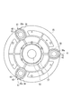
- the bearing plate 35 is provided with three bosses 38 for housing the first element 41 of the rotation preventing mechanism 40 at equal intervals in the circumferential direction as shown in FIG.
- the anti-rotation mechanism 40 is a pin-crank type anti-rotation mechanism and includes a first element 41 and a second element 45.
- the scroll compressor 1 is provided with three anti-rotation mechanisms 40 corresponding to the three bosses 38.
- the first element 41 comprises a bearing 42.
- the bearing 42 is, for example, a ball bearing provided with an inner ring, an outer ring, and a spherical rolling element provided between the inner ring and the outer ring.
- a crank pin (first pin) 43 is fitted to the inner ring of the bearing 42, and the first element 41 is configured together with the bearing 42.
- the first element 41 is housed inside the boss 38 of the bearing plate 35, which boss 38 functions as a bearing box for the bearing 42.
- the second element 45 has the same configuration as the first element 41, and includes two bearings 46 and a crank pin (second pin) 47 inserted into the inner ring of the bearing 46.
- the second element 45 is accommodated and held in the accommodation chamber 11 c of the housing 10.
- crankpin 43 of the first element 41 and the crankpin 47 of the second element 45 are integrally connected via an eccentric shaft 44.
- the crankpin 43, the crankpin 47 and the eccentric shaft 44 are an integral crankshaft Configure
- the boss 38 has an inner wall 38a, as shown in FIG. 2, and the inner wall 38a regulates the amount and direction in which the bearing 42 is displaced.
- the opening of the inner wall 38 a has an elongated shape having a major axis in the radial direction of the bearing plate 35 and a minor axis in the circumferential direction of the bearing plate 35. That is, the boss 38 and the bearing 42 have such an anisotropy that the displacement amount of the bearing 42 (crank pin 47) permitted is large in the radial direction and small in the circumferential direction.
- the drive shaft 50 transmits the rotational drive force of a drive source (not shown), such as an electric motor, to the orbiting scroll 30.
- a drive source such as an electric motor
- the drive shaft 50 is provided at one end with a connection end 51 connected to a drive source, and provided at the other end with an eccentric shaft 53 held by a bearing 37 held by the bearing plate 35. It is done.
- the drive shaft 50 is rotatably supported by the housing 10 by two bearings of a main bearing 54 and a sub bearing 55.
- the main bearing 54 supports the drive shaft 50 near the eccentric shaft 53
- the auxiliary bearing 55 supports the drive shaft 50 near the connection end 51.
- the scroll compressor 1 is a 3D type scroll compressor, high step portions 21b and 31b, in which both the back surface of the fixed scroll 20 and the back surface of the orbiting scroll 30 are centrally located, are recessed.
- the heights of the cooling fins 24 and the cooling fins 34 in the relevant portion are increased by using the depressions.
- the tips of the cooling fins 24 are aligned on the same plane in the central portion and the outer peripheral portion around the central portion. The same applies to the cooling fins 34. Therefore, the scroll compressor 1 can align the positions of the tips of the cooling fins 24 and 34 from the center to the outer periphery while increasing the height of the cooling fins 24 and 34 in the central portion.
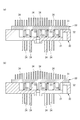
- the first embodiment is for the 3D type scroll compressor 1, but as shown in FIGS. 3 and 4, the present invention can be applied to scroll compressors other than 3D type.
- FIG. 3A and FIG. 3B the cooling fins 24 and the cooling fins 34 provided on the fixed scroll 20 and the orbiting scroll 30 whose back surfaces of the end plate 21 and the end plate 31 are both flat are respectively from the outer peripheral portion.
- FIG. 3 (a) shows an example in which the heights of the cooling fins 24 and the cooling fins 34 gradually increase
- FIG. 3 (b) shows the heights of the cooling fins 24 and the cooling fins 34 continuously higher.
- An example is shown.
- the example of two steps of a high step and a low step is shown here as a stepwise example, it can also be made three or more steps.
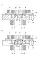
- the end plate 21 and the end The thickness of the plate 31 can be reduced stepwise (FIG. 4 (a)) or continuously (FIG. 4 (b)) towards the central part.
- the roots of the cooling fins 24 and the cooling fins 34 can be aligned on the same plane. In this way, it is possible to avoid occupying an unnecessary space by projecting the cooling fins 24 and 34 located in the central portion, and, for example, a portion corresponding to the cooling fins 24 of the first housing 10a is A flat shape is sufficient.
- the present invention shows an example in which the heights of both the cooling fins 24 of the fixed scroll 20 and the cooling fins 34 of the orbiting scroll 30 become high in the central portion
- the present invention And allows the height of only one of the orbiting scrolls 30 to be increased.
- the present invention can also be applied to the case where cooling fins are provided on only one of the fixed scroll 20 and the orbiting scroll 30.
- the cooling performance of the central portion is improved by increasing the heights of the cooling fins 24 and the cooling fins 34 in the central portion.
- the cooling fins 24 and the cooling fins 34 are further provided.
- the cooling ability of the central portion can also be improved by adjusting the density, thickness and the like.
- the scroll compressor 1 is merely an example, and the present invention can be widely applied to a scroll compressor provided with cooling fins.
Abstract
Provided is a scroll compressor in which a fixed scroll and an orbiting scroll can be cooled effectively through cooling fins. This scroll compressor (1) is provided with a fixed scroll (20), an orbiting scroll (30) which revolves around the fixed scroll (20) and combines to form a compression space for compressing a fluid between itself and the fixed scroll (20), and cooling fins (24) disposed on the back surface of the fixed scroll (20) and cooling fins (34) disposed on the back surface of the orbiting scroll (30). The backs of the cooling fins (24) and the cooling fins (34) in the central area are higher than in the periphery.
Description
本発明は、スクロール圧縮機の冷却フィンの改良に関する。
The present invention relates to the improvement of cooling fins of a scroll compressor.
スクロール圧縮機は、固定スクロールと、旋回スクロールとを備えている。固定スクロールおよび旋回スクロールは、いずれも円板状の端板の一面側に、渦巻状のラップが設けられたものである。このような固定スクロールと旋回スクロールとを、ラップを噛み合わせた状態で対向させ、固定スクロールに対して旋回スクロールを公転旋回運動させる。そして、双方のスクロールの間に形成される圧縮空間の容積を旋回スクロールの旋回に伴って減少させることで、その空間内の流体の圧縮を行う。
The scroll compressor includes a fixed scroll and a orbiting scroll. The fixed scroll and the orbiting scroll are both provided with a spiral wrap on one side of the disk-shaped end plate. The fixed scroll and the orbiting scroll are opposed to each other in a state where the wraps are engaged, and the orbiting scroll is revolved with respect to the stationary scroll. Then, the volume of the compression space formed between the two scrolls is reduced as the orbiting scroll turns, thereby compressing the fluid in the space.
スクロール圧縮機において、固定スクロールの端板及び旋回スクロールの端板の各々の背面に多数の冷却フィンを設け、流体の圧縮に伴う圧縮熱、および各部の回転に伴う摩擦熱を放散させるようにしたものが知られている(例えば、特許文献1~特許文献3)。特に、主に潤滑のための冷凍機油を用いないオイルフリー型のスクロール圧縮機において、冷却フィンを介した空冷が採用されている。
In the scroll compressor, a large number of cooling fins are provided on the back face of each of the fixed scroll end plate and the orbiting scroll end plate so as to dissipate the heat of compression associated with fluid compression and the heat of friction associated with the rotation of each part. Those are known (for example, Patent Document 1 to Patent Document 3). In particular, in an oil-free type scroll compressor that does not use refrigeration oil mainly for lubrication, air cooling via cooling fins is adopted.
スクロール圧縮機は、スクロールの外周側から圧縮の対象となる流体を吸入して、中央に向けて圧縮を徐々に進める。圧縮された流体は、固定スクロールの中央部分に設けられるポートから外部に吐出される。流体は圧縮の程度が大きくなると温度が高くなるために、スクロールは中央部分ほど高温に晒されることになる。
そこで本発明は、スクロールの中央部分の冷却を効果的に行うことのできるスクロール圧縮機を提供することを目的とする。 The scroll compressor sucks fluid to be compressed from the outer peripheral side of the scroll and gradually advances compression toward the center. The compressed fluid is discharged from the port provided at the central portion of the fixed scroll. The scroll is exposed to higher temperatures in the central portion because the fluid is at a higher temperature as the degree of compression increases.
Then, an object of this invention is to provide the scroll compressor which can perform cooling of the center part of a scroll effectively.
かかる目的のもとなされた、本発明のスクロール圧縮機は、正面に固定側ラップ部と背面に固定側冷却フィン部とが設けられる固定スクロールと、固定スクロールとの間に流体を圧縮する圧縮空間を形成するように組み合わされ、正面に旋回側ラップ部と背面に旋回側冷却フィン部とが設けられる旋回スクロールと、を備え、複数のフィンからなる固定側冷却フィン部、及び、複数のフィンからなる旋回側冷却フィン部(の一方又は双方)は、半径方向の中央部分に位置するフィンの方が、中央部分の周囲の外周部分に位置するフィンよりも、背が高いことを特徴とする。
The scroll compressor according to the present invention, which has been made for this purpose, has a compression space for compressing fluid between a fixed scroll provided with a fixed side wrap and a fixed side cooling fin provided on the front and the fixed scroll. From a plurality of fixed-side cooling fin portions comprising a plurality of fins, and from a plurality of fins, and a rotating scroll having a turning-side lap portion on the front and a turning-side cooling fin portion on the back. The turning side cooling fin portion (one or both) is characterized in that the fins located at the radially central portion are taller than the fins located at the outer peripheral portion around the central portion.
本発明のスクロール圧縮機によると、中央部分に位置するフィンの方が外周部分に位置するフィンよりも背が高く、伝熱面積が広いので、スクロールの中央部分の冷却を効果的に行うことができる。
According to the scroll compressor of the present invention, the fins located at the central portion are taller than the fins located at the outer peripheral portion and the heat transfer area is wider, so that the central portion of the scroll can be effectively cooled. it can.
本発明のスクロール圧縮機において、固定側冷却フィン部、及び、旋回側冷却フィン部の一方又は双方は、中央部分に向けて段階的に、又は、連続的に、背を高くすることができる。
連続的に背を高くすれば、流体の圧縮の度合いに対応する冷却能を得ることができるので、冷却能の向上の点では優れる。一方で、段階的に背を高くする方は、背の高さを設定することも含めて、製造が容易である。 In the scroll compressor according to the present invention, one or both of the stationary side cooling fin portion and the turning side cooling fin portion can be heightened stepwise or continuously toward the central portion.
If the height is continuously increased, the cooling capacity corresponding to the degree of compression of the fluid can be obtained, and thus the improvement of the cooling capacity is excellent. On the other hand, if the height is gradually increased, it is easy to manufacture, including setting the height of the height.
本発明のスクロール圧縮機において、固定側冷却フィン部、及び、旋回側冷却フィン部の一方又は双方は、その先端が同一平面上に揃っていることが好ましい。
そうすることにより、周囲に不必要なスペースが占有されるのを避けることができるとともに、例えば、ハウジングの類の冷却フィンに対応する部分が平坦な形状で足りる。 In the scroll compressor according to the present invention, it is preferable that one or both of the stationary side cooling fin portion and the turning side cooling fin portion have their tips aligned on the same plane.
By doing so, it is possible to avoid that the unnecessary space is occupied in the surroundings and, for example, the portion corresponding to the cooling fin of the kind of the housing needs to be flat.
固定側冷却フィン部、及び、旋回側冷却フィン部の一方又は双方の先端を同一平面上に揃えるには、固定側冷却フィン部が設けられる固定側端板、及び、旋回側冷却フィン部が設けられる旋回側端板(の一方又は双方)の肉厚を、中央部分の方を、中央部分の周囲の外周部分よりも薄くすればよい。
この構成を備えるスクロール圧縮機としては、固定側ラップ部、及び、旋回側ラップ部が、各々、歯先、及び、根元に段差を設けることで、外周部分の方が中央部分よりも背が高い、いわゆる3Dスクロール圧縮機が掲げられる。 In order to align the ends of one or both of the stationary side cooling fin portion and the turning side cooling fin portion on the same plane, a stationary side end plate provided with the stationary side cooling fin portion and a turning side cooling fin portion are provided. The thickness of (one or both) of the pivoting end plates may be thinner in the central portion than in the peripheral portion around the central portion.
In the scroll compressor provided with this configuration, the outer peripheral portion is taller than the central portion by providing steps on the tooth tip and the root of the stationary side lap portion and the turning side lap portion. So-called 3D scroll compressors are raised.
本発明のスクロール圧縮機によると、中央部分に位置するフィンの方が外周部分に位置するフィンよりも背が高く、伝熱面積が広いので、スクロールの中央部分の冷却を効果的に行うことができる。
According to the scroll compressor of the present invention, the fins located at the central portion are taller than the fins located at the outer peripheral portion and the heat transfer area is wider, so that the central portion of the scroll can be effectively cooled. it can.
以下、添付図面に示す実施の形態に基づいてこの発明を詳細に説明する。
[第1実施形態]
本実施形態のスクロール圧縮機1は、図1及び図2に示すように、スクロール圧縮機1の外殻をなすハウジング10と、ハウジング10に固定される固定スクロール20と、ハウジング10の内部に旋回可能に収容される旋回スクロール30とを主たる構成要素として備えている。これらの主たる構成要素は、アルミニウム系合金、鉄系合金等の金属材料から形成されている。
スクロール圧縮機1は、周方向のみならず高さ方向にも流体を圧縮する三次元圧縮機構を採用することで高圧縮比を得ることができる、3Dスクロール(登録商標)と呼ばれるタイプのスクロール圧縮機である。 Hereinafter, the present invention will be described in detail based on the embodiment shown in the attached drawings.
First Embodiment
As shown in FIGS. 1 and 2, the scroll compressor 1 according to the present embodiment is pivoted into ahousing 10 forming an outer shell of the scroll compressor 1, a fixed scroll 20 fixed to the housing 10, and the housing 10. An orbiting scroll 30 which can be accommodated is provided as a main component. These main components are formed of metal materials such as aluminum-based alloys and iron-based alloys.
The scroll compressor 1 can obtain a high compression ratio by adopting a three-dimensional compression mechanism that compresses fluid not only in the circumferential direction but also in the height direction, a type of scroll compression called 3D scroll (registered trademark) Machine.
[第1実施形態]
本実施形態のスクロール圧縮機1は、図1及び図2に示すように、スクロール圧縮機1の外殻をなすハウジング10と、ハウジング10に固定される固定スクロール20と、ハウジング10の内部に旋回可能に収容される旋回スクロール30とを主たる構成要素として備えている。これらの主たる構成要素は、アルミニウム系合金、鉄系合金等の金属材料から形成されている。
スクロール圧縮機1は、周方向のみならず高さ方向にも流体を圧縮する三次元圧縮機構を採用することで高圧縮比を得ることができる、3Dスクロール(登録商標)と呼ばれるタイプのスクロール圧縮機である。 Hereinafter, the present invention will be described in detail based on the embodiment shown in the attached drawings.
First Embodiment
As shown in FIGS. 1 and 2, the scroll compressor 1 according to the present embodiment is pivoted into a
The scroll compressor 1 can obtain a high compression ratio by adopting a three-dimensional compression mechanism that compresses fluid not only in the circumferential direction but also in the height direction, a type of scroll compression called 3D scroll (registered trademark) Machine.
[ハウジング10]
ハウジング10は、図1に示すように、第1ハウジング10aと、第2ハウジング10bとからなる密閉容器である。
第1ハウジング10aは、固定スクロール20に固定され、内部に固定スクロール20の冷却フィン24を収容する。第1ハウジング10aは、固定スクロール20の吐出ポート21eから吐出される圧縮流体を外部に向けて吐出する吐出ポート12を備えている。
第2ハウジング10bは、収容室11bの内部に、旋回スクロール30、自転防止機構40及び駆動軸50を収容し、かつ保持する。第2ハウジング10bは、収容室11bの内部に、自転防止機構40の第2要素45を収容する収容室11cと、駆動軸50及び主軸受54を収容する収容室11dを備えている。 [Housing 10]
Thehousing 10 is a sealed container comprising a first housing 10a and a second housing 10b as shown in FIG.
Thefirst housing 10 a is fixed to the fixed scroll 20 and accommodates the cooling fins 24 of the fixed scroll 20 therein. The first housing 10 a includes a discharge port 12 that discharges the compressed fluid discharged from the discharge port 21 e of the fixed scroll 20 to the outside.
Thesecond housing 10 b accommodates and holds the orbiting scroll 30, the rotation preventing mechanism 40, and the drive shaft 50 inside the accommodation chamber 11 b. The second housing 10 b includes a storage chamber 11 c for storing the second element 45 of the rotation preventing mechanism 40 and a storage chamber 11 d for storing the drive shaft 50 and the main bearing 54 in the storage chamber 11 b.
ハウジング10は、図1に示すように、第1ハウジング10aと、第2ハウジング10bとからなる密閉容器である。
第1ハウジング10aは、固定スクロール20に固定され、内部に固定スクロール20の冷却フィン24を収容する。第1ハウジング10aは、固定スクロール20の吐出ポート21eから吐出される圧縮流体を外部に向けて吐出する吐出ポート12を備えている。
第2ハウジング10bは、収容室11bの内部に、旋回スクロール30、自転防止機構40及び駆動軸50を収容し、かつ保持する。第2ハウジング10bは、収容室11bの内部に、自転防止機構40の第2要素45を収容する収容室11cと、駆動軸50及び主軸受54を収容する収容室11dを備えている。 [Housing 10]
The
The
The
[固定スクロール20]
固定スクロール20は、図1に示すように、概ね円板状に形成された端板21と、端板21の一方の面側に設けられる渦巻き状のラップ22と、端板21の他方の面側に設けられる冷却フィン24、固定スクロール20の最外周を取り囲む外周壁26とを備えており、例えばアルミニウム合金を鋳造することにより一体的に形成される。外周壁26には、圧縮の対象となる流体を吸い込む吸入口27が設けられている。また、外周壁26は、外部に露出しており、ハウジング10の一部を構成している。なお、固定スクロール20において、ラップ22が設けられる側を正面といい、冷却フィン24が設けられる側を背面ということにする。 [Fixed Scroll 20]
As shown in FIG. 1, thefixed scroll 20 has an end plate 21 formed in a substantially disc shape, a spiral wrap 22 provided on one surface side of the end plate 21, and the other surface of the end plate 21. The cooling fins 24 provided on the side and the outer peripheral wall 26 surrounding the outermost periphery of the fixed scroll 20 are integrally formed by casting, for example, an aluminum alloy. The outer peripheral wall 26 is provided with a suction port 27 for sucking a fluid to be compressed. The outer peripheral wall 26 is exposed to the outside and constitutes a part of the housing 10. In the fixed scroll 20, the side on which the wrap 22 is provided is referred to as the front, and the side on which the cooling fins 24 are provided is referred to as the back.
固定スクロール20は、図1に示すように、概ね円板状に形成された端板21と、端板21の一方の面側に設けられる渦巻き状のラップ22と、端板21の他方の面側に設けられる冷却フィン24、固定スクロール20の最外周を取り囲む外周壁26とを備えており、例えばアルミニウム合金を鋳造することにより一体的に形成される。外周壁26には、圧縮の対象となる流体を吸い込む吸入口27が設けられている。また、外周壁26は、外部に露出しており、ハウジング10の一部を構成している。なお、固定スクロール20において、ラップ22が設けられる側を正面といい、冷却フィン24が設けられる側を背面ということにする。 [Fixed Scroll 20]
As shown in FIG. 1, the
3Dタイプのスクロール圧縮機1は、ラップ22の背の高さが外周側よりも内周側が低くなるように、端板21に低段部21aと高段部21bを設けており、低段部21aに形成されるラップ22は背が高く、高段部21bに形成されるラップ22は背が低い。なお、低段部21aと高段部21bの境界の段差は、端板21の背面にも現れており、当該部分には、吐出ポート12を取り囲み、正面に向かって後退する凹溝21cが形成される。
ラップ22は、その先端に、旋回スクロール30の端板31と接触して封止する自己潤滑性を有するチップシール23が設けられている。 In the 3D type scroll compressor 1, thelow step 21a and the high step 21b are provided on the end plate 21 so that the height of the back of the wrap 22 is lower on the inner circumferential side than on the outer circumferential side. The wrap 22 formed on the top 21a is tall, and the wrap 22 formed on the high step 21b is short. A step at the boundary between the low step portion 21a and the high step portion 21b also appears on the back surface of the end plate 21, and in this portion, a recessed groove 21c is formed which recurs toward the front surface surrounding the discharge port 12 Be done.
Thewrap 22 is provided at its tip end with a self-lubricating tip seal 23 for sealing in contact with the end plate 31 of the orbiting scroll 30.
ラップ22は、その先端に、旋回スクロール30の端板31と接触して封止する自己潤滑性を有するチップシール23が設けられている。 In the 3D type scroll compressor 1, the
The
端板21には、表裏を貫通する吐出ポート21eが形成されており、固定スクロール20と旋回スクロール30により圧縮された流体は、吐出ポート21eを通って、吐出ポート12から外部に吐出される。
A discharge port 21e penetrating the front and back is formed in the end plate 21. The fluid compressed by the fixed scroll 20 and the orbiting scroll 30 is discharged from the discharge port 12 to the outside through the discharge port 21e.
端板21の背面には複数の冷却フィン24、すなわち固定側冷却フィン部が設けられており、ハウジング10に形成される開口(図示を省略)から流入する外気が冷却フィン24を通過することで、固定スクロール20を冷却する。本実施形態においては、複数の板状の冷却フィン24が同じ方向を向いて形成されているが、例えば、端板21の中央から放射状に複数の冷却フィン24を設けることもできる。これは、旋回スクロール30についても同様である。
冷却フィン24は、高段部21bと高段部21bを取り囲む低段部21aとで背の高さが相違し、中央に該当する高段部21bに設けられる冷却フィン24の背が高い。 A plurality ofcooling fins 24, that is, fixed side cooling fins, are provided on the back surface of the end plate 21, so that the outside air flowing in from the opening (not shown) formed in the housing 10 passes through the cooling fins 24. , Cool the fixed scroll 20. In the present embodiment, the plurality of plate-shaped cooling fins 24 are formed to face the same direction, but, for example, the plurality of cooling fins 24 may be provided radially from the center of the end plate 21. The same applies to the orbiting scroll 30.
The height of thecooling fin 24 is different between the high step 21b and the low step 21a surrounding the high step 21b, and the cooling fin 24 provided in the high step 21b corresponding to the center is tall.
冷却フィン24は、高段部21bと高段部21bを取り囲む低段部21aとで背の高さが相違し、中央に該当する高段部21bに設けられる冷却フィン24の背が高い。 A plurality of
The height of the
[旋回スクロール30]
旋回スクロール30は、図1に示すように、概ね円板状に形成された端板31と、端板31の一方の面側に設けられる渦巻き状のラップ32と、端板31の他方の面側に設けられる冷却フィン34とを備えており、例えばアルミニウム合金を鋳造することにより一体的に形成される。なお、旋回スクロール30において、ラップ32が設けられる側を正面といい、冷却フィン34が設けられる側を背面ということにする。 [Turning scroll 30]
As shown in FIG. 1, theorbiting scroll 30 has an end plate 31 formed in a substantially disc shape, a spiral wrap 32 provided on one surface side of the end plate 31, and the other surface of the end plate 31. It has cooling fins 34 provided on the side, and is integrally formed, for example, by casting an aluminum alloy. In the orbiting scroll 30, the side on which the wrap 32 is provided is referred to as the front, and the side on which the cooling fins 34 are provided is referred to as the back.
旋回スクロール30は、図1に示すように、概ね円板状に形成された端板31と、端板31の一方の面側に設けられる渦巻き状のラップ32と、端板31の他方の面側に設けられる冷却フィン34とを備えており、例えばアルミニウム合金を鋳造することにより一体的に形成される。なお、旋回スクロール30において、ラップ32が設けられる側を正面といい、冷却フィン34が設けられる側を背面ということにする。 [Turning scroll 30]
As shown in FIG. 1, the
旋回スクロール30のラップ32は、固定スクロール20のラップ22に対応しており、背の高さが外周側よりも内周側が低くなるように形成されている。また、端板31には低段部31aと高段部31bが設けられており、低段部31aに形成されるラップ32は背が高く、高段部31bに形成されるラップ32は背が低い。なお、低段部31aと高段部31bの境界の段差は、端板31の背面にも現れており、当該部分には、正面に向かって後退する凹溝31cが形成される。
ラップ32は、その先端に、固定スクロール20の端板21の正面側と接触して圧縮室を封止する自己潤滑性を有するチップシール33が設けられている。 Thewrap 32 of the orbiting scroll 30 corresponds to the wrap 22 of the fixed scroll 20, and is formed such that its height is lower on the inner peripheral side than on the outer peripheral side. The end plate 31 is provided with a low step 31a and a high step 31b. The wrap 32 formed on the low step 31a is tall and the wrap 32 formed on the high step 31b is tall Low. In addition, the level | step difference of the boundary of the low step part 31a and the high step part 31b has appeared also in the back of the end plate 31, and the concave groove 31c which recedes toward the front is formed in the said part.
Thewrap 32 is provided at its tip end with a self-lubricating tip seal 33 which contacts the front side of the end plate 21 of the fixed scroll 20 to seal the compression chamber.
ラップ32は、その先端に、固定スクロール20の端板21の正面側と接触して圧縮室を封止する自己潤滑性を有するチップシール33が設けられている。 The
The
端板31の背面には複数の冷却フィン34、すなわち旋回側冷却フィン部が設けられており、ハウジング10に形成される開口(図示を省略)から流入する外気が冷却フィン34を通過することで、旋回スクロール30を冷却する。複数の板状の冷却フィン34は、同じ方向を向いて形成されている。
冷却フィン24と同様に、冷却フィン34は、高段部31bと高段部31bを取り囲む低段部31aとで背の高さが相違し、中央に該当する高段部31bに設けられる冷却フィン34の背が高い。 A plurality of coolingfins 34, ie, turning side cooling fins, are provided on the back surface of the end plate 31, and outside air flowing from an opening (not shown) formed in the housing 10 passes through the cooling fins 34. , Cool the orbiting scroll 30. The plurality of plate-like cooling fins 34 are formed in the same direction.
Similar to the coolingfins 24, the cooling fins 34 have different heights between the high step 31b and the low step 31a surrounding the high step 31b, and the cooling fins are provided on the high step 31b corresponding to the center. 34 tall.
冷却フィン24と同様に、冷却フィン34は、高段部31bと高段部31bを取り囲む低段部31aとで背の高さが相違し、中央に該当する高段部31bに設けられる冷却フィン34の背が高い。 A plurality of cooling
Similar to the cooling
旋回スクロール30は、冷却フィン34の先端側に固定される軸受プレート35を備えている。
軸受プレート35は、中央部分に軸受37を収容し、かつ固定するボス36を備えている。ボス36に保持される軸受37は、駆動軸50の偏心軸53を支持している。
また、軸受プレート35は、自転防止機構40の第1要素41を収容する3つのボス38を、図2に示すように、周方向に等間隔で備えている。 The orbitingscroll 30 includes a bearing plate 35 fixed to the tip end side of the cooling fin 34.
The bearingplate 35 is provided with a boss 36 which accommodates and secures the bearing 37 at its central portion. A bearing 37 held by the boss 36 supports the eccentric shaft 53 of the drive shaft 50.
Further, the bearingplate 35 is provided with three bosses 38 for housing the first element 41 of the rotation preventing mechanism 40 at equal intervals in the circumferential direction as shown in FIG.
軸受プレート35は、中央部分に軸受37を収容し、かつ固定するボス36を備えている。ボス36に保持される軸受37は、駆動軸50の偏心軸53を支持している。
また、軸受プレート35は、自転防止機構40の第1要素41を収容する3つのボス38を、図2に示すように、周方向に等間隔で備えている。 The orbiting
The bearing
Further, the bearing
[自転防止機構40]
自転防止機構40は、ピンクランク式の自転防止機構であり、第1要素41と第2要素45を備えている。スクロール圧縮機1は、3つのボス38に対応して3つの自転防止機構40を備えている。
第1要素41は、軸受42を備える。軸受42は、例えば、内輪と、外輪と、内輪と外輪の間に設けられる球状の転動体とを備える玉軸受からなる。軸受42の内輪にはクランクピン(第1ピン)43が嵌合され、軸受42とともに第1要素41を構成する。第1要素41は、軸受プレート35のボス38の内部に収容されるが、このボス38は軸受42の軸受箱として機能する。
第2要素45は、第1要素41と同様の構成を有しており、2つの軸受46と、軸受46の内輪に挿入されるクランクピン(第2ピン)47と、を備えている。第2要素45は、ハウジング10の収容室11cに収容、保持される。 [Autorotation prevention mechanism 40]
Theanti-rotation mechanism 40 is a pin-crank type anti-rotation mechanism and includes a first element 41 and a second element 45. The scroll compressor 1 is provided with three anti-rotation mechanisms 40 corresponding to the three bosses 38.
Thefirst element 41 comprises a bearing 42. The bearing 42 is, for example, a ball bearing provided with an inner ring, an outer ring, and a spherical rolling element provided between the inner ring and the outer ring. A crank pin (first pin) 43 is fitted to the inner ring of the bearing 42, and the first element 41 is configured together with the bearing 42. The first element 41 is housed inside the boss 38 of the bearing plate 35, which boss 38 functions as a bearing box for the bearing 42.
Thesecond element 45 has the same configuration as the first element 41, and includes two bearings 46 and a crank pin (second pin) 47 inserted into the inner ring of the bearing 46. The second element 45 is accommodated and held in the accommodation chamber 11 c of the housing 10.
自転防止機構40は、ピンクランク式の自転防止機構であり、第1要素41と第2要素45を備えている。スクロール圧縮機1は、3つのボス38に対応して3つの自転防止機構40を備えている。
第1要素41は、軸受42を備える。軸受42は、例えば、内輪と、外輪と、内輪と外輪の間に設けられる球状の転動体とを備える玉軸受からなる。軸受42の内輪にはクランクピン(第1ピン)43が嵌合され、軸受42とともに第1要素41を構成する。第1要素41は、軸受プレート35のボス38の内部に収容されるが、このボス38は軸受42の軸受箱として機能する。
第2要素45は、第1要素41と同様の構成を有しており、2つの軸受46と、軸受46の内輪に挿入されるクランクピン(第2ピン)47と、を備えている。第2要素45は、ハウジング10の収容室11cに収容、保持される。 [Autorotation prevention mechanism 40]
The
The
The
第1要素41のクランクピン43と第2要素45のクランクピン47は、偏心軸44を介して一体的に接続されており、クランクピン43、クランクピン47及び偏心軸44は、一体のクランク軸を構成する。
The crankpin 43 of the first element 41 and the crankpin 47 of the second element 45 are integrally connected via an eccentric shaft 44. The crankpin 43, the crankpin 47 and the eccentric shaft 44 are an integral crankshaft Configure
ボス38は、図2に示すように、内壁38aを有しており、この内壁38aは軸受42が変位する量及び向きを規制する。この内壁38aの開口は、真円と異なり、軸受プレート35の半径方向に長径を有し、軸受プレート35の周方向に短径を有する長円形状をなしている。つまり、ボス38と軸受42は、許容される軸受42(クランクピン47)の変位量が、半径方向に大きく、周方向に小さいという異方性を有している。したがって、旋回スクロール30が仮に熱膨張したとしても、軸受42の半径方向の変位は吸収される一方で、軸受42が周方向へ変位する量を小さく抑えることができる。したがって、旋回スクロール30が固定スクロール20に対してねじれるのを抑制できる。
The boss 38 has an inner wall 38a, as shown in FIG. 2, and the inner wall 38a regulates the amount and direction in which the bearing 42 is displaced. Unlike the perfect circle, the opening of the inner wall 38 a has an elongated shape having a major axis in the radial direction of the bearing plate 35 and a minor axis in the circumferential direction of the bearing plate 35. That is, the boss 38 and the bearing 42 have such an anisotropy that the displacement amount of the bearing 42 (crank pin 47) permitted is large in the radial direction and small in the circumferential direction. Therefore, even if the orbiting scroll 30 thermally expands, the displacement of the bearing 42 in the radial direction is absorbed, and the amount of displacement of the bearing 42 in the circumferential direction can be suppressed to a small amount. Therefore, twisting of the orbiting scroll 30 with respect to the fixed scroll 20 can be suppressed.
[駆動軸50]
駆動軸50は、図示を省略する駆動源、例えば電動モータの回転駆動力を旋回スクロール30に伝達する。
駆動軸50は、図1に示すように、駆動源に接続される接続端51が一方端側に設けられ、軸受プレート35に保持される軸受37に保持される偏心軸53が他方端に設けられている。
駆動軸50は、主軸受54と副軸受55の二つの軸受により、ハウジング10に回転可能に支持されている。主軸受54は偏心軸53の近傍で駆動軸50を支持し、副軸受55は接続端51の近傍で駆動軸50を支持する。 [Drive shaft 50]
Thedrive shaft 50 transmits the rotational drive force of a drive source (not shown), such as an electric motor, to the orbiting scroll 30.
As shown in FIG. 1, thedrive shaft 50 is provided at one end with a connection end 51 connected to a drive source, and provided at the other end with an eccentric shaft 53 held by a bearing 37 held by the bearing plate 35. It is done.
Thedrive shaft 50 is rotatably supported by the housing 10 by two bearings of a main bearing 54 and a sub bearing 55. The main bearing 54 supports the drive shaft 50 near the eccentric shaft 53, and the auxiliary bearing 55 supports the drive shaft 50 near the connection end 51.
駆動軸50は、図示を省略する駆動源、例えば電動モータの回転駆動力を旋回スクロール30に伝達する。
駆動軸50は、図1に示すように、駆動源に接続される接続端51が一方端側に設けられ、軸受プレート35に保持される軸受37に保持される偏心軸53が他方端に設けられている。
駆動軸50は、主軸受54と副軸受55の二つの軸受により、ハウジング10に回転可能に支持されている。主軸受54は偏心軸53の近傍で駆動軸50を支持し、副軸受55は接続端51の近傍で駆動軸50を支持する。 [Drive shaft 50]
The
As shown in FIG. 1, the
The
[スクロール圧縮機1の動作]
次に、以上の構成を備えるスクロール圧縮機1の動作は以下の通りである。
図示を省略する駆動源の回転に従って駆動軸50が回転すると、旋回スクロール30が公転旋回運動を開始する。そうすると、吸入口27から吸入される流体は、ラップ22とラップ32によって形成される三日月形状の圧縮空間において圧縮され、中央部分に設けられる吐出ポート12から吐出される。
スクロール圧縮機1が動作している間に、自転防止機構40は、旋回スクロール30が自転するのを防止する。
また、スクロール圧縮機1が動作している間に、固定スクロール20の背面に設けられる冷却フィン24及び旋回スクロール30の背面に設けられる冷却フィン34を取り込まれた外気が通過することで、固定スクロール20及び旋回スクロール30が冷却される。 [Operation of scroll compressor 1]
Next, the operation of the scroll compressor 1 having the above configuration is as follows.
When thedrive shaft 50 is rotated according to the rotation of the drive source (not shown), the orbiting scroll 30 starts the orbiting motion. Then, the fluid sucked from the suction port 27 is compressed in the crescent-shaped compression space formed by the wrap 22 and the wrap 32 and discharged from the discharge port 12 provided in the central portion.
While the scroll compressor 1 is operating, therotation preventing mechanism 40 prevents the orbiting scroll 30 from rotating.
In addition, while the scroll compressor 1 is in operation, the outside air taken in passes through the coolingfins 24 provided on the back surface of the fixed scroll 20 and the cooling fins 34 provided on the back surface of the orbiting scroll 30. 20 and the orbiting scroll 30 are cooled.
次に、以上の構成を備えるスクロール圧縮機1の動作は以下の通りである。
図示を省略する駆動源の回転に従って駆動軸50が回転すると、旋回スクロール30が公転旋回運動を開始する。そうすると、吸入口27から吸入される流体は、ラップ22とラップ32によって形成される三日月形状の圧縮空間において圧縮され、中央部分に設けられる吐出ポート12から吐出される。
スクロール圧縮機1が動作している間に、自転防止機構40は、旋回スクロール30が自転するのを防止する。
また、スクロール圧縮機1が動作している間に、固定スクロール20の背面に設けられる冷却フィン24及び旋回スクロール30の背面に設けられる冷却フィン34を取り込まれた外気が通過することで、固定スクロール20及び旋回スクロール30が冷却される。 [Operation of scroll compressor 1]
Next, the operation of the scroll compressor 1 having the above configuration is as follows.
When the
While the scroll compressor 1 is operating, the
In addition, while the scroll compressor 1 is in operation, the outside air taken in passes through the cooling
[スクロール圧縮機1の効果]
次に、スクロール圧縮機1の効果を説明する。
流体が圧縮されると温度上昇するので、スクロール圧縮機1が駆動されている間に、固定スクロール20と旋回スクロール30は高温に晒され、熱膨張する。熱膨張が許容範囲を超えると、一方のスクロールの歯先と、他方のスクロールの歯底が接触し、旋回スクロール30の円滑な旋回運動を阻害するおそれがある。
ところが、冷却フィン24及び冷却フィン34を介して固定スクロール20と旋回スクロール30は冷却されるので、熱膨張を抑制することができる。特に、スクロール圧縮機1は、温度が高くなる固定スクロール20及び旋回スクロール30に設けられる冷却フィン24及び冷却フィン34は、中央部分の方が周囲よりも背が高いので、冷却能力が高い。 [Effect of the scroll compressor 1]
Next, the effect of the scroll compressor 1 will be described.
Since the temperature rises when the fluid is compressed, while the scroll compressor 1 is driven, the fixedscroll 20 and the orbiting scroll 30 are exposed to high temperatures and thermally expand. If the thermal expansion exceeds the allowable range, the tip of one scroll contacts the bottom of the other scroll, and the smooth turning motion of the turning scroll 30 may be impeded.
However, since the fixedscroll 20 and the orbiting scroll 30 are cooled via the cooling fins 24 and the cooling fins 34, thermal expansion can be suppressed. In particular, the scroll compressor 1 has a high cooling capacity since the cooling fins 24 and the cooling fins 34 provided on the fixed scroll 20 and the orbiting scroll 30 where the temperature is high are taller at the central portion than at the periphery.
次に、スクロール圧縮機1の効果を説明する。
流体が圧縮されると温度上昇するので、スクロール圧縮機1が駆動されている間に、固定スクロール20と旋回スクロール30は高温に晒され、熱膨張する。熱膨張が許容範囲を超えると、一方のスクロールの歯先と、他方のスクロールの歯底が接触し、旋回スクロール30の円滑な旋回運動を阻害するおそれがある。
ところが、冷却フィン24及び冷却フィン34を介して固定スクロール20と旋回スクロール30は冷却されるので、熱膨張を抑制することができる。特に、スクロール圧縮機1は、温度が高くなる固定スクロール20及び旋回スクロール30に設けられる冷却フィン24及び冷却フィン34は、中央部分の方が周囲よりも背が高いので、冷却能力が高い。 [Effect of the scroll compressor 1]
Next, the effect of the scroll compressor 1 will be described.
Since the temperature rises when the fluid is compressed, while the scroll compressor 1 is driven, the fixed
However, since the fixed
スクロール圧縮機1は、3Dタイプのスクロール圧縮機であるために、固定スクロール20の背面及び旋回スクロール30の背面はともに中央に位置する高段部21b,31bが窪んでいる。本実施形態は、この窪みを利用して、当該部分の冷却フィン24及び冷却フィン34の背を高くしている。一方で、中央部分及びその周囲の外周部分において、冷却フィン24の先端は同一平面上に並んでいる。冷却フィン34についても同様である。したがって、スクロール圧縮機1は、中央部分の冷却フィン24,34の背を高くしながらも、冷却フィン24,34の先端の位置を中央から外周に亘って揃えることができる。このことは、冷却フィン24,34の背を高くするために、中央部分に位置する冷却フィン24,34が突出することで周囲に不必要なスペースを占有するのを避けること、また、例えば、第1ハウジング10aの冷却フィン24に対応する部分が平坦な形状で足りること、を示唆している。
Since the scroll compressor 1 is a 3D type scroll compressor, high step portions 21b and 31b, in which both the back surface of the fixed scroll 20 and the back surface of the orbiting scroll 30 are centrally located, are recessed. In the present embodiment, the heights of the cooling fins 24 and the cooling fins 34 in the relevant portion are increased by using the depressions. On the other hand, the tips of the cooling fins 24 are aligned on the same plane in the central portion and the outer peripheral portion around the central portion. The same applies to the cooling fins 34. Therefore, the scroll compressor 1 can align the positions of the tips of the cooling fins 24 and 34 from the center to the outer periphery while increasing the height of the cooling fins 24 and 34 in the central portion. This avoids occupying an unnecessary space in the periphery by projecting the cooling fins 24, 34 located in the central portion in order to make the cooling fins 24, 34 taller, and, for example, It is suggested that the portion corresponding to the cooling fin 24 of the first housing 10a should be flat.
[第2実施形態]
第1実施形態は3Dタイプのスクロール圧縮機1についてのものであるが、図3及び図4に示すように、本発明は3Dタイプ以外のスクロール圧縮機に適用できる。
図3(a)、(b)には、端板21及び端板31の背面がともに平坦な固定スクロール20及び旋回スクロール30に設けられた冷却フィン24及び冷却フィン34が、各々、外周部よりも中央部の背が高く形成された例が示されている。その中で、図3(a)は冷却フィン24及び冷却フィン34の背が段階的に高くなる例を示し、図3(b)は冷却フィン24及び冷却フィン34の背が連続的に高くなる例を示している。なお、段階的の例として、ここでは高段と低段の二段階の例を示しているが、三段階以上にすることもできる。 Second Embodiment
The first embodiment is for the 3D type scroll compressor 1, but as shown in FIGS. 3 and 4, the present invention can be applied to scroll compressors other than 3D type.
In FIG. 3A and FIG. 3B, the coolingfins 24 and the cooling fins 34 provided on the fixed scroll 20 and the orbiting scroll 30 whose back surfaces of the end plate 21 and the end plate 31 are both flat are respectively from the outer peripheral portion. Also, an example is shown in which the central part is formed to be tall. Among them, FIG. 3 (a) shows an example in which the heights of the cooling fins 24 and the cooling fins 34 gradually increase, and FIG. 3 (b) shows the heights of the cooling fins 24 and the cooling fins 34 continuously higher. An example is shown. In addition, although the example of two steps of a high step and a low step is shown here as a stepwise example, it can also be made three or more steps.
第1実施形態は3Dタイプのスクロール圧縮機1についてのものであるが、図3及び図4に示すように、本発明は3Dタイプ以外のスクロール圧縮機に適用できる。
図3(a)、(b)には、端板21及び端板31の背面がともに平坦な固定スクロール20及び旋回スクロール30に設けられた冷却フィン24及び冷却フィン34が、各々、外周部よりも中央部の背が高く形成された例が示されている。その中で、図3(a)は冷却フィン24及び冷却フィン34の背が段階的に高くなる例を示し、図3(b)は冷却フィン24及び冷却フィン34の背が連続的に高くなる例を示している。なお、段階的の例として、ここでは高段と低段の二段階の例を示しているが、三段階以上にすることもできる。 Second Embodiment
The first embodiment is for the 3D type scroll compressor 1, but as shown in FIGS. 3 and 4, the present invention can be applied to scroll compressors other than 3D type.
In FIG. 3A and FIG. 3B, the cooling
図3(a)、(b)に示す例は、冷却フィン24及び冷却フィン34の先端の位置が不揃いであるが、図4(a)、(b)に示すように、端板21及び端板31の厚さを、中央部分に向けて段階的(図4(a))又は連続的(図4(b))に薄くすることができる。このように冷却フィン24及び冷却フィン34の根元を端板21及び端板31の側に延在させることにより、冷却フィン24及び冷却フィン34の先端を同一平面上に揃えることができる。そうすれば、中央部分に位置する冷却フィン24,34が突出することで不必要なスペースを占有するのを避けることができ、また、例えば、第1ハウジング10aの冷却フィン24に対応する部分が平坦な形状で足りる。
In the example shown in FIGS. 3A and 3B, although the positions of the tips of the cooling fins 24 and the cooling fins 34 are uneven, as shown in FIGS. 4A and 4B, the end plate 21 and the end The thickness of the plate 31 can be reduced stepwise (FIG. 4 (a)) or continuously (FIG. 4 (b)) towards the central part. By extending the roots of the cooling fins 24 and the cooling fins 34 toward the end plate 21 and the end plate 31 as described above, the tips of the cooling fins 24 and the cooling fins 34 can be aligned on the same plane. In this way, it is possible to avoid occupying an unnecessary space by projecting the cooling fins 24 and 34 located in the central portion, and, for example, a portion corresponding to the cooling fins 24 of the first housing 10a is A flat shape is sufficient.
以上、本発明の好適な実施形態を説明したが、本発明の主旨を逸脱しない限り、以上の実施形態で挙げた構成を取捨選択したり、他の構成に適宜変更したりすることが可能である。
Although the preferred embodiments of the present invention have been described above, the configurations described in the above embodiments can be selected or changed to other configurations as appropriate without departing from the spirit of the present invention. is there.
例えば、以上説明した実施形態は、固定スクロール20の冷却フィン24及び旋回スクロール30の冷却フィン34の両方の背の高さが中央部分において高くなる例を示したが、本発明は、固定スクロール20及び旋回スクロール30のいずれか一方のみの背を高くすることを許容する。また、本発明は、固定スクロール20及び旋回スクロール30のいずれか一方のみに冷却フィンが設けられる場合にも適用できる。
For example, although the embodiment described above shows an example in which the heights of both the cooling fins 24 of the fixed scroll 20 and the cooling fins 34 of the orbiting scroll 30 become high in the central portion, the present invention And allows the height of only one of the orbiting scrolls 30 to be increased. The present invention can also be applied to the case where cooling fins are provided on only one of the fixed scroll 20 and the orbiting scroll 30.
また、以上説明した実施形態は、中央部分の冷却フィン24及び冷却フィン34の背を高くすることにより、中央部分の冷却能を向上させているが、さらに、冷却フィン24及び冷却フィン34を設ける密度、板厚などを調整することにより、中央部分の冷却能を向上させることもできる。
In the embodiment described above, the cooling performance of the central portion is improved by increasing the heights of the cooling fins 24 and the cooling fins 34 in the central portion. However, the cooling fins 24 and the cooling fins 34 are further provided. The cooling ability of the central portion can also be improved by adjusting the density, thickness and the like.
その他に、スクロール圧縮機1はあくまで一例であり、本発明は、冷却フィンを備えるスクロール圧縮機に広く適用することができる。
Besides, the scroll compressor 1 is merely an example, and the present invention can be widely applied to a scroll compressor provided with cooling fins.
1 スクロール圧縮機
10 ハウジング
10a 第1ハウジング
10b 第2ハウジング
11b,11c,11d 収容室
12 吐出ポート
20 固定スクロール
30 旋回スクロール
21,31 端板
21a,31a 低段部
21b,31b 高段部
21c 凹溝
21e 吐出ポート
22,32 ラップ
23,33 チップシール
24,34 冷却フィン
26 外周壁
27 吸入口
31c 凹溝
35 軸受プレート
36,38 ボス
37 軸受
38a 内壁
40 自転防止機構
41 第1要素
42,46 軸受
43 クランクピン(第1ピン)
44 偏心軸
45 第2要素
47 クランクピン(第2ピン)
50 駆動軸
51 接続端
53 偏心軸 Reference Signs List 1scroll compressor 10 housing 10a first housing 10b second housing 11b, 11c, 11d accommodation chamber 12 discharge port 20 fixed scroll 30 orbiting scroll 21, 31 end plate 21a, 31a low step portion 21b, 31b high step portion 21c recessed groove 21e discharge port 22, 32 wrap 23, 33 tip seal 24, 34 cooling fin 26 outer peripheral wall 27 suction port 31 c recessed groove 35 bearing plate 36, 38 boss 37 bearing 38a inner wall 40 rotation preventing mechanism 41 first element 42, 46 bearing 43 Crank pin (first pin)
44Eccentric shaft 45 Second element 47 Crank pin (second pin)
50Drive shaft 51 Connection end 53 Eccentric shaft
10 ハウジング
10a 第1ハウジング
10b 第2ハウジング
11b,11c,11d 収容室
12 吐出ポート
20 固定スクロール
30 旋回スクロール
21,31 端板
21a,31a 低段部
21b,31b 高段部
21c 凹溝
21e 吐出ポート
22,32 ラップ
23,33 チップシール
24,34 冷却フィン
26 外周壁
27 吸入口
31c 凹溝
35 軸受プレート
36,38 ボス
37 軸受
38a 内壁
40 自転防止機構
41 第1要素
42,46 軸受
43 クランクピン(第1ピン)
44 偏心軸
45 第2要素
47 クランクピン(第2ピン)
50 駆動軸
51 接続端
53 偏心軸 Reference Signs List 1
44
50
Claims (6)
- 正面に固定側ラップ部と背面に固定側冷却フィン部とが設けられる固定スクロールと、
前記固定スクロールとの間に流体を圧縮する圧縮空間を形成するように組み合わされ、正面に旋回側ラップ部と背面に旋回側冷却フィン部とが設けられる旋回スクロールと、を備え、
複数のフィンからなる前記固定側冷却フィン部、及び、複数のフィンからなる前記旋回側冷却フィン部の一方又は双方は、
中央部分に位置するフィンの方が、前記中央部分の周囲の外周部分に位置するフィンよりも、背が高い、
ことを特徴とするスクロール圧縮機。 A stationary scroll having a stationary side wrap portion on the front side and a stationary side cooling fin portion on the back side;
And an orbiting scroll which is combined to form a compression space for compressing a fluid between the fixed scroll and the orbiting scroll, and the orbiting side wrap portion is provided on the front side and the orbiting side cooling fin portion is provided on the back side;
One or both of the stationary-side cooling fin portion including a plurality of fins and the swirl-side cooling fin portion including a plurality of fins
The fins located in the central portion are taller than the fins located in the outer peripheral portion around the central portion,
A scroll compressor characterized by - 前記固定側冷却フィン部、及び、前記旋回側冷却フィン部の一方又は双方は、
前記中央部分に向けて段階的に、又は、連続的に、背が高くなる、
請求項1に記載するスクロール圧縮機。 One or both of the fixed side cooling fin portion and the turning side cooling fin portion are
Become taller towards the central portion, either gradually or continuously,
The scroll compressor according to claim 1. - 前記固定側冷却フィン部、及び、前記旋回側冷却フィン部の一方又は双方は、
その先端が同一平面上に揃っている、
請求項1又は請求項2に記載のスクロール圧縮機。 One or both of the fixed side cooling fin portion and the turning side cooling fin portion are
The tips are aligned on the same plane,
The scroll compressor according to claim 1 or 2. - 前記固定側冷却フィン部が設けられる固定側端板、及び、前記旋回側冷却フィン部が設けられる旋回側端板の一方又は双方は、
半径方向の中央部分の方が、前記中央部分の周囲の外周部分よりも、肉厚が薄い、
請求項3に記載のスクロール圧縮機。 One or both of a stationary side end plate on which the stationary side cooling fin portion is provided, and a turning side end plate on which the turning side cooling fin portion is provided,
The radially central portion is thinner than the peripheral portion around the central portion;
The scroll compressor according to claim 3. - 前記固定側ラップ部、及び、前記旋回側ラップ部は、各々、
歯先、及び、根元に段差を設けることで、前記外周部分の方が前記中央部分よりも背が高い、
請求項4に記載のスクロール圧縮機。 The stationary side wrap portion and the turning side wrap portion are respectively
The outer peripheral portion is taller than the central portion by providing a step at the tooth tip and the root,
The scroll compressor according to claim 4. - 前記固定側冷却フィン部、及び、前記旋回側冷却フィン部の双方が、
前記中央部分に位置するフィンの方が、前記外周部分に位置するフィンよりも、背が高い、
請求項1に記載するスクロール圧縮機。 Both the stationary side cooling fin portion and the turning side cooling fin portion are
The fins located in the central portion are taller than the fins located in the outer peripheral portion,
The scroll compressor according to claim 1.
Priority Applications (3)
| Application Number | Priority Date | Filing Date | Title |
|---|---|---|---|
| CN201580007025.7A CN105960534A (en) | 2014-02-17 | 2015-01-05 | Scroll compressor |
| EP15748912.1A EP3109476B1 (en) | 2014-02-17 | 2015-01-05 | Scroll compressor |
| US15/117,206 US10125769B2 (en) | 2014-02-17 | 2015-01-05 | Scroll compressor |
Applications Claiming Priority (2)
| Application Number | Priority Date | Filing Date | Title |
|---|---|---|---|
| JP2014-027427 | 2014-02-17 | ||
| JP2014027427A JP6279926B2 (en) | 2014-02-17 | 2014-02-17 | Scroll compressor |
Publications (1)
| Publication Number | Publication Date |
|---|---|
| WO2015122110A1 true WO2015122110A1 (en) | 2015-08-20 |
Family
ID=53799864
Family Applications (1)
| Application Number | Title | Priority Date | Filing Date |
|---|---|---|---|
| PCT/JP2015/000011 WO2015122110A1 (en) | 2014-02-17 | 2015-01-05 | Scroll compressor |
Country Status (5)
| Country | Link |
|---|---|
| US (1) | US10125769B2 (en) |
| EP (1) | EP3109476B1 (en) |
| JP (1) | JP6279926B2 (en) |
| CN (1) | CN105960534A (en) |
| WO (1) | WO2015122110A1 (en) |
Families Citing this family (7)
| Publication number | Priority date | Publication date | Assignee | Title |
|---|---|---|---|---|
| FR3062430B1 (en) | 2017-01-27 | 2021-05-21 | Danfoss Commercial Compressors | SPIRAL COMPRESSOR WITH ORBITAL DISCS LUBRICATION SYSTEM |
| JP6787814B2 (en) * | 2017-02-17 | 2020-11-18 | 三菱重工業株式会社 | Double rotation scroll type compressor and its assembly method |
| WO2018181229A1 (en) | 2017-03-29 | 2018-10-04 | 日本電産サンキョー株式会社 | Work description creating device for industrial robot, and work description creating method for industrial robot |
| JP6698726B2 (en) * | 2018-03-12 | 2020-05-27 | 三菱重工業株式会社 | Double rotary scroll compressor |
| CN108443142B (en) * | 2018-05-18 | 2019-09-03 | 东北大学 | A kind of bilateral twin-stage vortex dry vacuum pump |
| CN110118181A (en) * | 2019-06-18 | 2019-08-13 | 南京永升新能源技术有限公司 | A kind of oil-free scroll air compressor machine that heat dissipation performance is excellent |
| CN111927770A (en) * | 2020-07-27 | 2020-11-13 | 周岩 | Three-dimensional gas scroll compression structure |
Citations (4)
| Publication number | Priority date | Publication date | Assignee | Title |
|---|---|---|---|---|
| JPH06249168A (en) * | 1993-02-23 | 1994-09-06 | Tokico Ltd | Scroll fluid machine |
| JPH09144673A (en) * | 1995-11-20 | 1997-06-03 | Tokico Ltd | Scroll type fluid machinery |
| JPH10502719A (en) * | 1994-07-19 | 1998-03-10 | インガーソル ランド カンパニー | Air cooling device for spiral compressor |
| JP2002213376A (en) * | 2001-01-19 | 2002-07-31 | Anest Iwata Corp | Scroll fluid machine |
Family Cites Families (14)
| Publication number | Priority date | Publication date | Assignee | Title |
|---|---|---|---|---|
| JPH0738717Y2 (en) | 1987-02-06 | 1995-09-06 | 岩田塗装機工業株式会社 | Air cooled scroll compressor |
| JPH0645670Y2 (en) | 1987-09-30 | 1994-11-24 | 岩田塗装機工業株式会社 | Cooling device for air-cooled oilless scroll compressor |
| JP3424881B2 (en) | 1995-09-01 | 2003-07-07 | トキコ株式会社 | Scroll type fluid machine |
| JP4026099B2 (en) * | 1998-10-15 | 2007-12-26 | アネスト岩田株式会社 | Scroll fluid machinery |
| JP4028179B2 (en) | 2001-03-06 | 2007-12-26 | アネスト岩田株式会社 | Scroll fluid machinery |
| JP4074075B2 (en) * | 2001-09-19 | 2008-04-09 | アネスト岩田株式会社 | Scroll fluid machinery |
| JP4031223B2 (en) | 2001-09-27 | 2008-01-09 | アネスト岩田株式会社 | Scroll type fluid machine |
| CN100371598C (en) | 2003-08-11 | 2008-02-27 | 三菱重工业株式会社 | Scroll compressor |
| US7309219B2 (en) * | 2003-12-26 | 2007-12-18 | Hitachi, Ltd. | Scroll type fluid machinery |
| JP4948869B2 (en) * | 2006-03-28 | 2012-06-06 | アネスト岩田株式会社 | Scroll fluid machinery |
| JP2010084592A (en) * | 2008-09-30 | 2010-04-15 | Hitachi Ltd | Scroll fluid machine |
| JP5386219B2 (en) * | 2009-04-27 | 2014-01-15 | 三菱重工業株式会社 | Scroll compressor |
| JP5236619B2 (en) * | 2009-11-30 | 2013-07-17 | 株式会社日立産機システム | Injection scroll air compressor |
| JP5596577B2 (en) * | 2011-01-26 | 2014-09-24 | 株式会社日立産機システム | Scroll type fluid machine |
-
2014
- 2014-02-17 JP JP2014027427A patent/JP6279926B2/en active Active
-
2015
- 2015-01-05 CN CN201580007025.7A patent/CN105960534A/en active Pending
- 2015-01-05 EP EP15748912.1A patent/EP3109476B1/en active Active
- 2015-01-05 US US15/117,206 patent/US10125769B2/en active Active
- 2015-01-05 WO PCT/JP2015/000011 patent/WO2015122110A1/en active Application Filing
Patent Citations (4)
| Publication number | Priority date | Publication date | Assignee | Title |
|---|---|---|---|---|
| JPH06249168A (en) * | 1993-02-23 | 1994-09-06 | Tokico Ltd | Scroll fluid machine |
| JPH10502719A (en) * | 1994-07-19 | 1998-03-10 | インガーソル ランド カンパニー | Air cooling device for spiral compressor |
| JPH09144673A (en) * | 1995-11-20 | 1997-06-03 | Tokico Ltd | Scroll type fluid machinery |
| JP2002213376A (en) * | 2001-01-19 | 2002-07-31 | Anest Iwata Corp | Scroll fluid machine |
Non-Patent Citations (1)
| Title |
|---|
| See also references of EP3109476A4 * |
Also Published As
| Publication number | Publication date |
|---|---|
| JP6279926B2 (en) | 2018-02-14 |
| JP2015151954A (en) | 2015-08-24 |
| EP3109476A1 (en) | 2016-12-28 |
| US10125769B2 (en) | 2018-11-13 |
| CN105960534A (en) | 2016-09-21 |
| EP3109476A4 (en) | 2017-12-06 |
| EP3109476B1 (en) | 2021-12-22 |
| US20160341200A1 (en) | 2016-11-24 |
Similar Documents
| Publication | Publication Date | Title |
|---|---|---|
| WO2015122110A1 (en) | Scroll compressor | |
| JP4422208B2 (en) | Expander integrated compressor | |
| JP4775494B2 (en) | Scroll compressor | |
| JP5888897B2 (en) | Scroll member and scroll type fluid machine | |
| JP2010196663A (en) | Compressor | |
| US9732753B2 (en) | Scroll compressor with inclined surfaces on the stepped portions | |
| JP6081577B2 (en) | Scroll compressor | |
| JP6042530B2 (en) | Scroll compressor | |
| JP2002266777A (en) | Scroll fluid machine provided with multi-stage fluid compression part | |
| JP6335542B2 (en) | Scroll compressor | |
| JPS6343427Y2 (en) | ||
| JP6137876B2 (en) | Scroll compressor for refrigerator | |
| JP6539020B2 (en) | Scroll compressor | |
| JP5622473B2 (en) | Scroll compressor | |
| JP5001334B2 (en) | Scroll type fluid machine | |
| JPS6256356B2 (en) | ||
| US11002274B2 (en) | Scroll fluid machine including first and second scroll members | |
| WO2015068308A1 (en) | Scroll compressor | |
| JP6444786B2 (en) | Scroll compressor | |
| JP4706599B2 (en) | Scroll compressor | |
| JP5979974B2 (en) | Scroll compressor and design method thereof | |
| JP7267087B2 (en) | Air conditioning compressor | |
| JP2005139977A (en) | Scroll type fluid machine | |
| JP2009156234A (en) | Hermetic scroll compressor for helium | |
| JP2002276571A (en) | Scroll type fluid machine |
Legal Events
| Date | Code | Title | Description |
|---|---|---|---|
| 121 | Ep: the epo has been informed by wipo that ep was designated in this application |
Ref document number: 15748912 Country of ref document: EP Kind code of ref document: A1 |
|
| REEP | Request for entry into the european phase |
Ref document number: 2015748912 Country of ref document: EP |
|
| WWE | Wipo information: entry into national phase |
Ref document number: 2015748912 Country of ref document: EP |
|
| WWE | Wipo information: entry into national phase |
Ref document number: 15117206 Country of ref document: US |
|
| NENP | Non-entry into the national phase |
Ref country code: DE |