WO2015118762A1 - 投影制御装置 - Google Patents
投影制御装置 Download PDFInfo
- Publication number
- WO2015118762A1 WO2015118762A1 PCT/JP2014/082281 JP2014082281W WO2015118762A1 WO 2015118762 A1 WO2015118762 A1 WO 2015118762A1 JP 2014082281 W JP2014082281 W JP 2014082281W WO 2015118762 A1 WO2015118762 A1 WO 2015118762A1
- Authority
- WO
- WIPO (PCT)
- Prior art keywords
- projection
- obstacle
- image
- range
- unit
- Prior art date
- Legal status (The legal status is an assumption and is not a legal conclusion. Google has not performed a legal analysis and makes no representation as to the accuracy of the status listed.)
- Ceased
Links
Images


Classifications
-
- H—ELECTRICITY
- H04—ELECTRIC COMMUNICATION TECHNIQUE
- H04N—PICTORIAL COMMUNICATION, e.g. TELEVISION
- H04N9/00—Details of colour television systems
- H04N9/12—Picture reproducers
- H04N9/31—Projection devices for colour picture display, e.g. using electronic spatial light modulators [ESLM]
- H04N9/3191—Testing thereof
- H04N9/3194—Testing thereof including sensor feedback
-
- G—PHYSICS
- G03—PHOTOGRAPHY; CINEMATOGRAPHY; ANALOGOUS TECHNIQUES USING WAVES OTHER THAN OPTICAL WAVES; ELECTROGRAPHY; HOLOGRAPHY
- G03B—APPARATUS OR ARRANGEMENTS FOR TAKING PHOTOGRAPHS OR FOR PROJECTING OR VIEWING THEM; APPARATUS OR ARRANGEMENTS EMPLOYING ANALOGOUS TECHNIQUES USING WAVES OTHER THAN OPTICAL WAVES; ACCESSORIES THEREFOR
- G03B21/00—Projectors or projection-type viewers; Accessories therefor
- G03B21/14—Details
-
- H—ELECTRICITY
- H04—ELECTRIC COMMUNICATION TECHNIQUE
- H04N—PICTORIAL COMMUNICATION, e.g. TELEVISION
- H04N9/00—Details of colour television systems
- H04N9/12—Picture reproducers
- H04N9/31—Projection devices for colour picture display, e.g. using electronic spatial light modulators [ESLM]
- H04N9/3179—Video signal processing therefor
- H04N9/3185—Geometric adjustment, e.g. keystone or convergence
Definitions
- the present invention relates to control of a projection device that projects an image or control of a robot that includes a projection device.
- Patent Document 1 discloses a robot that selects an optimal projection target surface that is most easily viewable by a person based on an indoor layout and the position of the person.
- Patent Document 2 discloses a robot apparatus that determines a projection destination for projecting information according to an external situation and the content of information to be projected.
- Patent Document 1 has a problem that it cannot be applied to an indoor space where the indoor layout is not recorded because it uses a pre-recorded indoor layout (such as curtain, chase, and picture layout information).
- indoor layout such as curtain, chase, and picture layout information.
- Patent Document 2 since the projection destination is selected according to the number of people around and whether or not the information to be projected is a secret content, there is an obstacle to the projection of information. When a possible object appears, there is a problem that it is difficult to perform projection that is easy for the user to read.
- the present invention has been made in view of the above problems, and an object of the present invention is to provide a projection control device and the like for projecting the content of the projected image in a range where the user can easily read the content.
- a projection control apparatus is a projection control apparatus that projects an image on a projection apparatus, and the projection apparatus projects an image from the projection apparatus.
- An obstacle detection unit that detects an obstacle that hinders projection of an image between one projection range and the obstacle detection unit detects an image in the first projection range when the obstacle is detected by the obstacle detection unit.
- a projection operation changing unit that changes an operation to project.
- the projection control apparatus can change the current projection operation so as to avoid the obstacle. Therefore, it is possible to perform projection that is easy to be visually recognized by the user without any obstacles that hinder the projection of the video.
- FIG. 5 is a flowchart illustrating a process for changing a projection space as an example of a process of S6 in FIG. 4.
- FIG. 5 is a flowchart illustrating a process for changing a projection space as an example of a process of S6 in FIG. 4.
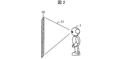
- FIG. 2 is a schematic diagram schematically showing that an image is projected by the robot according to the embodiment of the present invention.
- the robot 1 projects an image on a projection range 10 that is determined in advance as an area on which the image is projected.
- the projection is projected on the projection range 10.
- the content may not be displayed properly.
- the present invention changes the operation related to the image projection by the robot 1 in response to the change in the current state in the projection space 11.
- the output unit is mounted on a self-propelled robot will be described as a specific example.
- the output unit only needs to change the projection range at least automatically.
- Embodiment 1 when an obstacle exists in the projection space 11 (see FIG. 2) before the image is projected by the robot 1, the operation related to the image projection by the robot 1 is changed. Further, the projection range 10 (see FIG. 2) before the image is projected by the robot 1 is a surface that is determined in advance as a region on which the image is projected. The surface may be a surface (screen, wall, etc.) that is likely to be used for projection, a surface searched by the robot 1, or a surface instructed by the user. An embodiment of the present invention will be described below with reference to FIG. 1 and FIGS.
- FIG. 1 is a block diagram showing a main configuration of a robot according to an embodiment of the present invention.
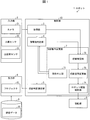
- the robot 1 includes an input unit 2, an output unit (projection device) 6, a drive unit 8, a storage unit 9, and a control unit (projection control device) 13.
- the control unit 13 includes an acquisition unit 3, an obstacle determination unit (obstacle detection unit) 4, a projection range determination unit 5, and a projection operation change unit 7.
- the input unit 2 detects the current state of the projection space 11 (see FIG. 2).
- the input unit 2 includes sensors such as a camera 21, a human sensor 22, and an ultrasonic sensor 23.
- the acquisition unit 3 acquires projection space information indicating the current state of the projection space 11 from the input unit 2.
- the obstacle determination unit 4 refers to the projection space information (for example, the shape, size, and type of the object existing in the projection space 11) from the acquisition unit 3, and obstructs the projection of the image in the projection space 11. Determine (detect) whether there is an object. Details of the input unit 2 and the obstacle determination unit 4 will be described later with reference to FIG.
- the projection range determination unit 5 uses the projection range 10 that is determined in advance as the projection range in which the video information is projected. Confirm as The output unit 6 outputs the video data 91 to the projection range determined by the projection range determination unit 5.
- the output unit 6 includes a projector 61.
- the storage unit 9 stores a control program executed by the control unit 13 and various data used by the robot 1.
- the storage unit 9 stores video data 91.
- the video data 91 is video data projected by the robot 1.
- the video data 91 is read by the control unit 13 and transmitted to the output unit 6.
- the video data 91 may be any data that can be output (projected) by the output unit 6, and the format is not particularly limited.
- the video data 91 may be still image data or moving image data.
- the projection operation changing unit 7 changes the operation of projecting an image in a predetermined projection range when the obstacle determining unit 4 determines that there is an obstacle in the projection space 11.
- the projection operation change unit 7 includes a projection stop unit (projection operation change unit) 71, a state identification unit 72, a projection space change unit (projection operation change unit) 73, and a robot drive control unit (movement control unit) 74.
- the projection cancellation unit 71 stops the robot 1 from projecting the image to the predetermined projection range 10.
- the projection stopping unit 71 causes the robot 1 to display an image. Stop projecting.
- the state specifying unit 72 specifies the position or moving direction of the obstacle.
- the projection space changing unit 73 changes at least one of the projection range 10, the position of the robot 1 that projects the image, or the projection direction of the image projected by the robot 1, and the projection space 11 is determined in advance.
- the projection space is changed to a projection space different from the predetermined projection space.
- the projection space changing unit 73 changes the projection range 10 from a predetermined projection range (first projection range) to a projection range (second projection range) different from the predetermined projection range.
- the robot drive control unit 74 notifies the drive unit 8 that the robot 1 is driven so that the projection space 11 becomes the projection space changed by the projection space changing unit 73.
- the drive unit 8 drives the robot 1 according to an instruction from the robot drive control unit 74. For example, when the position of the robot 1 is changed by the projection space changing unit 73, the robot drive control unit 74 moves (walks) the robot 1 to the position changed by the projection space changing unit 73. 8 is notified. For example, when the projection direction of the image projected by the robot 1 is changed by the projection space changing unit 73, the robot drive control unit 74 drives the robot 1 in the direction changed by the projection space changing unit 73. To the drive unit 8. More specifically, when the projector 61 is provided on the head (not shown) of the robot 1 and the projection direction for projecting an image on the neck (not shown) of the robot 1 is provided, the driving is performed. The unit 8 changes the neck direction of the robot 1.
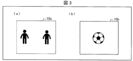
- FIG. 3 is a diagram illustrating an example of a projection space visually recognized by a robot according to an embodiment of the present invention.
- FIG. 3A shows that the object existing in the projection space 11 (see FIG. 2) is a human.
- the human face is detected by the camera 21, and the human body temperature is detected by the human sensor 22.
- the obstacle determination unit 4 detects that the human is in the projection space 11 based on the projection space information indicating the human face and the human body temperature notified from the camera 21 and the human sensor 22 via the acquisition unit 3. It is determined that there is an obstacle in the projection space 11 that hinders the projection of the image.
- FIG. 3B is a figure which shows that the object which exists in the projection space 11 (refer FIG. 2) is not a human being.
- the object is detected by the ultrasonic sensor 23, and the distance between the object and the robot 1 is measured by the camera 21.
- the obstacle determination unit 4 performs projection based on the projection space information indicating the presence / absence of the object and the distance between the object and the robot 1 notified from the camera 21 and the ultrasonic sensor 23 via the acquisition unit 3. It is detected that the shape of the object existing in the space 11 is a sphere, and it is determined that there is an obstacle in the projection space 11 that hinders the projection of the image.
- the obstacle determination unit 4 can detect the shape of the object existing in the projection space 11 using the distance measured by the camera 21. For example, when the shape of the object existing in the projection space 11 is a sphere as shown in FIG. 3B, the object may interfere with the display of the projected image. 4 determines that there is an obstacle in the projection space that hinders the projection of the image. For example, when the size of the object existing in the projection space 11 is small with respect to the display content of the projected image, the shape of the object has a small distortion in the display of the projected image, and thus the obstacle determination unit 4 Determines that there is no obstacle in the projection space 11 that hinders the projection of the image.
- FIG. 4 is a flowchart showing processing when projection is started by the robot.
- the projection range 10 before the image is projected by the robot 1 is an arbitrary plane determined in advance.
- the projection range 10 is in a predetermined state (S1).
- the acquisition unit 3 acquires projection space information indicating the current state of the projection space 11 (see FIG. 2) from the input unit 2 (S2).
- the obstacle determination unit 4 refers to the projection space information to determine whether there is an obstacle in the projection space 11 that prevents the projection of the image (S3).
- the projection range determination unit 5 sets the predetermined projection range (first projection range) 10 as A projection range for projecting an image is determined (S4).
- the output unit 6 starts projecting an image on the projection range determined by the projection range determination unit 5 (S5).
- the projection operation change unit 7 determines the projection range (first projection)
- the operation for projecting the video is changed to (range) 10 (S6).
- the process in S6 is “stops the operation of projecting onto the predetermined projection range (first projection range) 10” or “the projection range is determined as the predetermined projection range (first projection range)”. To a projection range different from the predetermined projection range (first projection range) ”.
- the projection stopping unit 71 determines a predetermined projection.
- the robot 1 is stopped from projecting an image in the range 10. (S6). And after S6, you may repeat the process after S1. Of the processes in S6, “changing the projection range” will be described in detail with reference to FIGS.
- the obstacle determined by the obstacle determination unit 4 is a human or when the obstacle is moving, the obstacle is expected to leave the projection space 11. Therefore, even if the projection range 10 is not changed, there is a high possibility that the projection space 11 is changed from a state where an obstacle exists to a state where no obstacle exists. Therefore, after the projection is stopped, it is possible to project an image in a state where there is no object that can be an obstacle in the projection space 11.
- FIG. 5 is a diagram illustrating an example of an imaging range in which a camera provided in the robot captures a projection range.
- a human is positioned on the left side of the shooting range 12a.
- a human is positioned on the right side of the shooting range 12b.
- FIG. A human is located in the center of the imaging range 12c.
- FIG. 6 is a flowchart showing a process for changing the projection range 10 as an example of the process of S6 in FIG.
- the state specifying unit 72 specifies that the position of the obstacle with respect to the imaging range 12 is biased in the projection range 10 (see FIG. 2) (YES in S61)
- the projection space changing unit 73 Is changed to a direction in which the deviation of the position of the obstacle is small (S62).
- the projection space changing unit 73 changes at least one of the projection range 10, the position of the robot 1 that projects the video, or the projection direction of the video projected by the robot 1, thereby changing the projection range 10 and the projection.
- the space 11 is changed.
- the robot drive control unit 74 drives the robot 1 to a position where an image can be projected onto the projection space changed by the projection space changing unit 73. Then, the projection range changed by the projection space changing unit 73 is newly determined as a projection range in which the robot projects an image (S63), and the processes after S2 are repeated.
- the obstacle determination unit 4 determines that an obstacle exists in the projection space 11 (see FIG. 2).
- the state specifying unit 72 specifies that the position of the obstacle with respect to the shooting range 12a is on the left side of the center of the shooting range 12a with reference to the shooting range 12a notified via the acquisition unit 3.
- the projection space changing unit 73 changes the projection range to the side opposite to the position of the obstacle specified by the state specifying unit 72, that is, to the right side of the center of the imaging range 12a (S62).
- the robot drive control unit 74 moves the robot 1 via the drive unit 8 to a position where an image can be projected onto the projection range changed by the projection space changing unit 73.
- the projection range changed by the projection space changing unit 73 is newly determined as a projection range in which the robot projects an image (S63), and the processes after S2 are repeated.
- the projection space changing unit 73 sets the projection space 11 to the predetermined range. (S64).
- the predetermined direction may be a default setting or may be set in advance by the user.
- the robot 1 is driven to a position where video information can be projected onto the projection range in the projection space changed by the projection space changing unit 73. And the process after S63 is repeated.
- the state specifying unit 72 refers to the shooting range 12c notified via the acquisition unit 3, and the position of the obstacle with respect to the shooting range 12c is the center of the shooting range 12c. Specify that it is not biased against.
- the projection space changing unit 73 changes the projection range 10 in a predetermined direction (S64).
- FIG. 7 is a diagram illustrating an example of an imaging range in which a camera provided in the robot captures a projection range.
- FIG. 7A is a diagram showing that a person is located on the left side of the shooting range 12c and that the person is moving in the right direction with respect to the center of the shooting range 12c.
- FIG. 7B is a diagram illustrating that a person is located on the right side of the shooting range 12d and that the person is moving leftward with respect to the center of the shooting range 12c.
- FIG. 8 is a flowchart showing a process when a video is projected by the robot.
- the robot 1 is in a state of projecting an image on the projection range 10 (see FIG. 2) (S11).
- the projection stopping unit 71 stops the projection of the video ( S13).
- the projection range determination unit 5 determines the projection range for projecting the projection range 10 in S11. The projection of the video by the output unit 6 is resumed (S15).
- the camera 21 detects a human face or a human shape and also detects a human movement. Then, the obstacle determination unit 4 detects that a person is moving in the projection space 11 (see FIG. 2), and determines that there is an obstacle in the projection space 11 (S12).
- projection of an image on a human is likely to cause severe distortion in the display of the projection and is not friendly to the human eye.
- humans are likely to move constantly. For this reason, when the obstacle determined by the obstacle determination unit 4 is a person, after the projection is stopped in a state where a person is present in the projection space 11, the projection space 11 is in a state where there is no person, An image can be projected.
- FIG. 9 is a flowchart showing processing when a video is projected by the robot.
- the robot 1 is in a state of projecting an image on the projection range 10 (see FIG. 2) (S21).
- the projection stopping unit 71 stops the projection of the video ( S23).
- the state specifying unit 72 specifies the moving direction of the obstacle, and the projection space
- the changing unit 73 changes the projection range from the projection range 10 in S21 to the direction (opposite side) opposite to the moving direction of the obstacle (S25).
- the projection range determination unit 5 determines the projection range for projecting the video to the projection range changed by the projection space changing unit 73, and resumes the projection of the video by the output unit 6 (S26).
- the projection range in S25 is Be changed.
- the state identification unit 72 identifies that the obstacle determined by the obstacle determination unit 4 has moved to the right with respect to the center of the imaging range 12c (S24). ). For this reason, the projection space changing unit 73 changes the projection range from the projection range 10 in S21 to the left direction different from the movement of the obstacle (S25).
- FIG. 10 is a flowchart showing a process when a video is projected by the robot.
- the robot 1 is in a state of projecting an image on the projection range 10 (see FIG. 2) (S31).
- the obstacle determination unit 4 determines that there is an obstacle in the projection space 11 (see FIG. 2) (YES in S32)
- the projection space changing unit 73 enters the projection range 10 in S31.
- the position of the robot 1 that projects the image and the projection direction of the image projected by the robot 1 are changed (S33).
- the details of the process of changing the position of the robot 1 in S33, as shown in the process in S61 to S64 (Embodiment 1) described above, is a process of changing the direction in which there are few obstacles that prevent the robot 1 from projecting an image. But you can. Further, when an obstacle that prevents the projection of the image by the robot 1 is moving, as shown in the processing in S24 to S25 (Embodiment 3) described above, the direction in which the obstacle that prevents the projection of the image moves. May be processed in the opposite direction.
- the robot drive control unit 74 moves (walks, etc.) the robot 1 that projects the image, and changes the projection direction of the image projected by the robot 1. 8 is notified. Thereby, the image projection by the robot 1 is continuously performed without changing the projection range 10 in S31.
- the projection range determination unit 5 displays the projection range changed by the projection space change unit 73. Then, the projection range for projecting the video is determined (S35).
- control blocks (particularly, the acquisition unit 3, the obstacle determination unit 4, the projection range determination unit 5, and the projection operation change unit 7) of the projection control apparatus (control unit 13) are formed in an integrated circuit (IC chip) or the like. It may be realized by a circuit (hardware) or may be realized by software using a CPU (Central Processing Unit).
- IC chip integrated circuit
- CPU Central Processing Unit
- the projection control apparatus includes a CPU that executes instructions of a program that is software that realizes each function, a ROM (Read Only Memory) in which the program and various data are recorded so as to be readable by a computer (or CPU), or A storage device (these are referred to as “recording media”), a RAM (Random Access Memory) for expanding the program, and the like are provided.
- a computer or CPU
- the objective of this invention is achieved when a computer (or CPU) reads the said program from the said recording medium and runs it.
- a “non-temporary tangible medium” such as a tape, a disk, a card, a semiconductor memory, a programmable logic circuit, or the like can be used.
- the program may be supplied to the computer via an arbitrary transmission medium (such as a communication network or a broadcast wave) that can transmit the program.
- a transmission medium such as a communication network or a broadcast wave
- the present invention can also be realized in the form of a data signal embedded in a carrier wave in which the program is embodied by electronic transmission.
- the projection control device (control unit 13) is a projection control device that projects an image on the projection device (output unit 6), and the projection device projects an image from the projection device.
- the obstacle detection unit obstacle determination unit 4
- a projection operation changing unit (7) that changes an operation of projecting an image on the first projection range.
- the projection control device Change the operation of projecting video to the projection range. For this reason, the projection control apparatus can change the current projection operation so as to avoid the obstacle. Therefore, it is possible to perform projection that is easy to be visually recognized by the user without any obstacles that hinder the projection of the video.
- the projection operation changing unit projects the image onto the first projection range. May be canceled.
- the projection control apparatus can stop projecting the image so as to avoid projecting the image on the obstacle. Therefore, it is possible to perform projection that is easy to be visually recognized by the user without any obstacles that hinder the projection of the video.
- a projection control device is the projection control device according to aspect 1, wherein when the obstacle is detected by the obstacle detection unit, the projection operation change unit projects an image by the projection device.
- the range may be changed from the first projection range to a second projection range different from the first projection range.
- the projection control apparatus changes the projection range for projecting the video from the first projection range to the second projection different from the first projection range so as to avoid the projection of the video onto the obstacle. Can be changed to range. Therefore, it is possible to perform projection that is easy to be visually recognized by the user without any obstacles that hinder the projection of the video.
- the projection control device includes the state specifying unit that specifies the position or moving direction of the obstacle in the aspect 3, and the projection operation changing unit includes the specified position of the obstacle or Depending on the moving direction, the projection range may be changed to avoid the obstacle.
- the projection control device determines the state identification.
- the projection range is changed according to the position or moving direction of the obstacle specified by the unit so as to avoid projection of an image on the obstacle. For this reason, the projection range can be changed to a position where there are few obstacles that hinder the projection of the image, or to the opposite side to the direction in which the obstacles move.
- the projection control apparatus is the projection control apparatus according to aspect 4, in which the state specifying unit specifies the position of the obstacle, and the projection operation changing unit is configured so that the position of the obstacle is viewed from the projection apparatus. If the first projection range is biased to one side, the projection range may be changed from the first projection range to the second projection range on the other side.
- the projection range can be changed to a position where there are few obstacles that hinder the projection of the image. Therefore, projection can be performed while avoiding obstacles.
- the state specifying unit specifies a moving direction of the obstacle
- the projection operation changing unit sets the projection range from the first projection range. You may change to the said 2nd projection range on the opposite side to the moving direction of the said obstruction.
- the projection range can be changed to the side opposite to the direction in which the obstacle that hinders the projection of the image moves. For this reason, an image can be projected while avoiding moving obstacles. Further, even if there is an obstacle that moves to the changed second projection range, the obstacle is closer to the end of the projection range in the moving direction. Therefore, it is possible to shorten the time from when there is an obstacle to when there is no obstacle.
- the projection control apparatus is the projection control apparatus according to aspect 1, in accordance with the state specifying unit (72) that specifies the position or moving direction of the obstacle and the specified position or moving direction of the obstacle.
- a movement control unit (movement drive unit 74) that moves the projection device to a position where an image can be projected onto the first projection range while avoiding the obstacle may be provided.
- the projection control apparatus moves while adjusting the projection direction of projection by the projection apparatus, and therefore projects the image on one projection range in a state where there is no obstacle that prevents the projection of the image. It is possible to continue. Therefore, it is possible to perform projection that is easy to be visually recognized by the user without any stress on the user visually recognizing the projected image, as if there are no obstacles that hinder the projection of the image.
- the projection control apparatus may be realized by a computer, and in this case, the projection that realizes the projection control apparatus by a computer by causing the computer to operate as each unit included in the projection control apparatus.
- a control program for the control device and a computer-readable recording medium on which the control program is recorded also fall within the scope of the present invention.
- a control method of a projection control apparatus is a control method of a projection control apparatus that projects an image on a projection apparatus, and the first projection range in which an image is projected by the projection apparatus from the projection apparatus.
- An obstacle detection step for detecting an obstacle that hinders the projection of an image, and an operation of projecting an image on the first projection range when the obstacle is detected in the obstacle detection step.
- a projection operation changing step for changing the projection control method.
- a robot (1) according to aspect 9 of the present invention includes the projection control apparatus according to any one of aspects 1 to 7, and a projection apparatus that projects an image.
- the present invention can be used in a projection apparatus that projects video data such as still images and moving images.
Landscapes
- Engineering & Computer Science (AREA)
- Multimedia (AREA)
- Signal Processing (AREA)
- Physics & Mathematics (AREA)
- Geometry (AREA)
- General Physics & Mathematics (AREA)
- Projection Apparatus (AREA)
- Controls And Circuits For Display Device (AREA)
- Manipulator (AREA)
- Transforming Electric Information Into Light Information (AREA)
Abstract
投影される映像の内容をユーザが読み取り易い範囲に投影する。投影装置(6)から、投影装置によって映像が投影される第1投影範囲までの間にある、映像の投影を妨げる障害物を検知する障害物判定部(4)と、映像の投影を妨げる障害物が検知された場合に、第1投影範囲映像を投影する動作を変更する投影動作変更部(7)と、を備える。
Description
本発明は、映像を投影する投影装置の制御、または投影装置を備えるロボットの制御に関する。
人間とロボットとのコミュニケーションにおいて、ロボットが映像を用いて人間に情報を伝達する方法が従来技術として知られている。例えば、下記の特許文献1には、室内レイアウトと人間の位置とにより、当該人間が最も見やすい最適投影対象面を選択するロボットが開示されている。また、下記の特許文献2には、外部の状況及び投影する情報の内容に応じて、当該情報を投影する投影先を決定するロボット装置が開示されている。
しかしながら、特許文献1の技術では、予め記録された室内レイアウト(カーテン、タンス、絵画の配置情報など)を用いるため、室内レイアウトが記録されていない室内空間では適用できないという問題がある。また、特許文献2の技術では、周囲にいる人間の数、および投影する情報が秘密の内容であるか否かに応じて、投影先を選択する構成であるため、情報の投影に対して障害となり得る物体が出現した場合、ユーザが読み取り易い投影を行うことができないという問題がある。
本発明は、上記の問題点に鑑みてなされたものであり、その目的は、投影される映像の内容をユーザが読み取り易い範囲に、投影する投影制御装置等を提供することである。
上記の課題を解決するために、本発明の一態様に係る投影制御装置は、投影装置に映像を投影させる投影制御装置であって、上記投影装置から、該投影装置によって映像が投影される第1投影範囲までの間にある、映像の投影を妨げる障害物を検知する障害物検知部と、上記障害物検知部によって、上記障害物が検知された場合に、上記第1投影範囲に映像を投影する動作を変更する投影動作変更部と、を備える。
本発明の一態様によれば、投影制御装置は、当該障害物を避けるように、現在の投影する動作を変更できる。それゆえ、映像の投影を妨げる障害物がない状態で、ユーザによって視認されやすい投影を行うことが可能となる。
(ロボット1による投影の概要)
図2は、本発明の一実施形態に係るロボットによって映像が投影されていることを概略的に示す模式図である。図2に示されるように、ロボット1は、映像が投影される領域として予め決定された投影範囲10に、映像を投影する。しかしながら、投影範囲10と、投影範囲10に映像を投影するロボット1の出力部(不図示)までの間における投影空間11に、障害物がある場合(不図示)、投影範囲10に投影される内容が適切に表示されないことがある。本発明は、投影空間11における現在の状態の変化に対応して、ロボット1による映像の投影に関する動作を変更するものである。なお、以下の実施形態では、具体例として、出力部が自走式ロボットに搭載されている場合について説明するが、出力部は少なくとも自動で投影範囲を変更可能であればよい。
図2は、本発明の一実施形態に係るロボットによって映像が投影されていることを概略的に示す模式図である。図2に示されるように、ロボット1は、映像が投影される領域として予め決定された投影範囲10に、映像を投影する。しかしながら、投影範囲10と、投影範囲10に映像を投影するロボット1の出力部(不図示)までの間における投影空間11に、障害物がある場合(不図示)、投影範囲10に投影される内容が適切に表示されないことがある。本発明は、投影空間11における現在の状態の変化に対応して、ロボット1による映像の投影に関する動作を変更するものである。なお、以下の実施形態では、具体例として、出力部が自走式ロボットに搭載されている場合について説明するが、出力部は少なくとも自動で投影範囲を変更可能であればよい。
〔実施形態1〕
本実施形態では、ロボット1によって映像が投影される前において、投影空間11(図2参照)に障害物が存在する場合、ロボット1による映像の投影に関する動作が変更される。また、ロボット1によって映像が投影される前における投影範囲10(図2参照)は、映像が投影される領域として予め決定された面である。当該面は、投影に活用される可能性の高い面(スクリーン、壁等)でもよいし、ロボット1によって検索された面でもよいし、ユーザによって指示された面でもよい。以下、本発明の一実施形態について図1および図3~図6を参照して説明する。
本実施形態では、ロボット1によって映像が投影される前において、投影空間11(図2参照)に障害物が存在する場合、ロボット1による映像の投影に関する動作が変更される。また、ロボット1によって映像が投影される前における投影範囲10(図2参照)は、映像が投影される領域として予め決定された面である。当該面は、投影に活用される可能性の高い面(スクリーン、壁等)でもよいし、ロボット1によって検索された面でもよいし、ユーザによって指示された面でもよい。以下、本発明の一実施形態について図1および図3~図6を参照して説明する。
(ロボット1の構成)
図1は、本発明の一実施形態に係るロボットの要部構成を示すブロック図である。図1に示されるように、ロボット1は、入力部2、出力部(投影装置)6、駆動部8、記憶部9および制御部(投影制御装置)13を備える。制御部13は、取得部3、障害物判定部(障害物検知部)4、投影範囲確定部5および投影動作変更部7を備える。
図1は、本発明の一実施形態に係るロボットの要部構成を示すブロック図である。図1に示されるように、ロボット1は、入力部2、出力部(投影装置)6、駆動部8、記憶部9および制御部(投影制御装置)13を備える。制御部13は、取得部3、障害物判定部(障害物検知部)4、投影範囲確定部5および投影動作変更部7を備える。
入力部2は、投影空間11(図2参照)の現在の状態を検知する。例えば、入力部2は、カメラ21、人感センサ22および超音波センサ23のようなセンサにより構成される。取得部3は、投影空間11の現在の状態を示す投影空間情報を入力部2から取得する。障害物判定部4は、取得部3からの投影空間情報(例えば、投影空間11に存在する物体の形状、大きさ、および種別など)を参照して、投影空間11に映像の投影を妨げる障害物があるか否かを判定(検知)する。入力部2および障害物判定部4の詳細については、図3にて後述する。
投影範囲確定部5は、障害物判定部4によって、投影空間11に映像の投影を妨げる障害物がないと判定された場合、予め決定されている投影範囲10を、映像情報を投影する投影範囲として確定する。出力部6は、投影範囲確定部5によって確定された投影範囲に、映像データ91を出力するものである。例えば、出力部6はプロジェクタ61により構成される。
記憶部9は、制御部13が実行する制御プログラム、および、ロボット1が使用する各種データを記憶するものである。また、記憶部9は、映像データ91を格納している。映像データ91は、ロボット1が投影する映像のデータである。映像データ91は、制御部13により読み出され、出力部6へと送信される。なお、映像データ91は、出力部6が出力(投影)可能なデータであればよく、その形式は特に限定されない。また、映像データ91は、静止画のデータであっても動画データであっても構わない。
投影動作変更部7は、障害物判定部4によって、投影空間11に障害物があると判定された場合に、予め決定された投影範囲に映像を投影する動作を変更する。投影動作変更部7は、投影中止部(投影動作変更部)71、状態特定部72、投影空間変更部(投影動作変更部)73、およびロボット駆動制御部(移動制御部)74を備える。
投影中止部71は、障害物判定部4によって、投影空間11に映像の投影を妨げる障害物があると判定された場合、予め決められた投影範囲10にロボット1が映像を投影することを中止させる。例えば、障害物判定部4によって判定された障害物が人である場合、または、障害物判定部4によって判定された障害物が移動している場合、投影中止部71は、ロボット1が映像を投影することを中止させる。
状態特定部72は、障害物判定部4によって、投影空間11に映像の投影を妨げる障害物があると判定された場合、当該障害物の位置または移動方向を特定する。
投影空間変更部73は、投影範囲10、映像を投影するロボット1の位置、またはロボット1によって投影される映像の投影方向のうち、少なくとも1つを変更し、投影空間11を、予め決定された投影空間から、予め決定された投影空間とは異なる投影空間に変更する。例えば、投影空間変更部73は、投影範囲10を、予め決定されている投影範囲(第1投影範囲)から、予め決定された投影範囲とは異なる投影範囲(第2投影範囲)に変更する。
ロボット駆動制御部74は、投影空間11が、投影空間変更部73によって変更された投影空間となるように、ロボット1を駆動させることを駆動部8に通知する。駆動部8は、ロボット駆動制御部74から指示によって、ロボット1を駆動させる。例えば、投影空間変更部73によってロボット1の位置が変更された場合、ロボット駆動制御部74は、投影空間変更部73によって変更された位置に、ロボット1を移動(歩行)させることを、駆動部8に通知する。また、例えば、投影空間変更部73によって、ロボット1によって投影される映像の投影方向が変更された場合、ロボット駆動制御部74は、投影空間変更部73によって変更された方向に、ロボット1を駆動させることを、駆動部8に通知する。より具体的には、ロボット1の頭部(不図示)にプロジェクタ61が備えられ、かつロボット1の首(不図示)に映像を投影する投影方向を調整する構成が備えられている場合、駆動部8はロボット1における首の方向を変更させる。
(障害物の判定)
図3は、本発明の一実施形態に係るロボットによって視認された投影空間の一例を示す図である。図3の(a)は、投影空間11(図2参照)に存在する物体が人間であることを示す図である。図3の(a)の場合、カメラ21によって人間の顔が検知されるとともに、人感センサ22によって人間の体温が検知される。そして、障害物判定部4は、カメラ21および人感センサ22から取得部3を経由して通知された、人間の顔および人間の体温を示す投影空間情報に基づいて、投影空間11に人間が存在することを検出し、投影空間11に、映像の投影を妨げる障害物があると判定する。
図3は、本発明の一実施形態に係るロボットによって視認された投影空間の一例を示す図である。図3の(a)は、投影空間11(図2参照)に存在する物体が人間であることを示す図である。図3の(a)の場合、カメラ21によって人間の顔が検知されるとともに、人感センサ22によって人間の体温が検知される。そして、障害物判定部4は、カメラ21および人感センサ22から取得部3を経由して通知された、人間の顔および人間の体温を示す投影空間情報に基づいて、投影空間11に人間が存在することを検出し、投影空間11に、映像の投影を妨げる障害物があると判定する。
図3の(b)は、投影空間11(図2参照)に存在する物体が人間ではないことを示す図である。図3の(b)の場合、超音波センサ23によって当該物体が検知されるとともに、カメラ21によって当該物体とロボット1との距離が計測される。そして、障害物判定部4は、カメラ21および超音波センサ23から取得部3を経由して通知された、物体の有無および当該物体とロボット1との距離を示す投影空間情報に基づいて、投影空間11に存在する物体の形状は球であることを検出し、投影空間11に、映像の投影を妨げる障害物があると判定する。
ここで、障害物判定部4は、カメラ21によって計測される距離を用いて、投影空間11に存在する物体の形状を検知することができる。例えば、投影空間11に存在する物体の形状が、図3の(b)に示されるような球状である場合、当該物体は投影する映像の表示の妨げとなる虞があるため、障害物判定部4は、投影空間に、映像の投影を妨げる障害物があると判定する。なお、例えば、投影空間11に存在する物体の大きさが、投影する映像の表示内容に対して小さい場合、当該物体の形状は、投影する映像の表示の歪みが小さいため、障害物判定部4は、投影空間11に、映像の投影を妨げる障害物がないと判定する。
(投影開始における処理)
図4は、ロボットにより投影が開始される場合の処理を示すフローチャートである。なお、前述した通り、ロボット1によって映像が投影される前における投影範囲10は、予め決定された任意の面とする。
図4は、ロボットにより投影が開始される場合の処理を示すフローチャートである。なお、前述した通り、ロボット1によって映像が投影される前における投影範囲10は、予め決定された任意の面とする。
図4に示されるように、投影範囲10は予め決定された状態である(S1)。取得部3は、入力部2から投影空間11(図2参照)の現在の状態を示す投影空間情報を取得する(S2)。次に、障害物判定部4は、投影空間情報を参照して、投影空間11に映像の投影を妨げる障害物があるか否かを判定する(S3)。障害物判定部4によって、投影空間11に障害物がないと判定された場合(S3にてYES)、投影範囲確定部5は、予め決定されている投影範囲(第1投影範囲)10を、映像を投影する投影範囲として確定する(S4)。そして、出力部6は、投影範囲確定部5によって確定された投影範囲に、映像を投影することを開始する(S5)。
一方、S2の後、障害物判定部4によって、投影空間11に障害物があると判定された場合(S3にてNO)、投影動作変更部7は、予め決定された投影範囲(第1投影範囲)10に、映像を投影する動作を変更する(S6)。S6における処理は、具体的には、“予め決定された投影範囲(第1投影範囲)10に投影する動作を中止する”または“投影範囲を、予め決定された投影範囲(第1投影範囲)から、予め決定された投影範囲(第1投影範囲)とは異なる投影範囲に変更する”ことを意味する。
例えば、障害物判定部4によって判定された障害物が人間である場合、または、障害物判定部4によって判定された障害物が移動している場合、投影中止部71は、予め決められた投影範囲10にロボット1が映像を投影することを中止させる。(S6)。そして、S6の後、S1以降の処理を繰り返してもよい。なお、S6における処理のうち、“投影範囲を変更する”ことについては、図5および6にて詳細に説明する。
ここで、障害物判定部4によって判定された障害物が人間である場合、または、当該障害物が移動している場合、当該障害物は、投影空間11から離れることが予想される。ゆえに、投影範囲10を変更せずとも、投影空間11は、障害物が存在する状態から無い状態に変わる可能性が高い。それゆえ、投影を中止した後に、投影空間11に障害となり得る物体が無い状態で、映像を投影することが可能となる。
(投影範囲の変更)
図5は、ロボットに備えられたカメラが、投影範囲を撮影した撮影範囲の例を示す図である。図5の(a)では、撮影範囲12aの左側に人間が位置しており、図5の(b)では、撮影範囲12bの右側に人間が位置しており、図5の(c)では、撮影範囲12cの中央に人間が位置する。
図5は、ロボットに備えられたカメラが、投影範囲を撮影した撮影範囲の例を示す図である。図5の(a)では、撮影範囲12aの左側に人間が位置しており、図5の(b)では、撮影範囲12bの右側に人間が位置しており、図5の(c)では、撮影範囲12cの中央に人間が位置する。
図6は、図4におけるS6の処理の一例として、投影範囲10を変更する場合の処理を示すフローチャートである。状態特定部72により、撮影範囲12に対する障害物の位置が、投影範囲10(図2参照)において偏っていると特定された場合(S61にてYES)、投影空間変更部73は、投影範囲10を、障害物の位置の偏りが少ない方向に変更する(S62)。投影範囲10の変更に応じて投影空間11が変更されることにより、出力部6は、障害物を避けて投影を行うことができる。なお、投影空間変更部73は、投影範囲10、映像を投影するロボット1の位置、またはロボット1によって投影される映像の投影方向のうち、少なくとも1つを変更することにより、投影範囲10および投影空間11を変更する。
次に、ロボット駆動制御部74は、投影空間変更部73によって変更された投影空間に映像を投影できる位置に、ロボット1を駆動させる。そして、投影空間変更部73によって変更された投影範囲が、ロボットが映像を投影する投影範囲として新たに決定され(S63)、S2以降の処理を繰り返す。
例えば、図5の(a)の場合、障害物判定部4は、投影空間11(図2参照)に障害物が存在すると判定する。状態特定部72は、取得部3を経由して通知された撮影範囲12aを参照して、障害物の撮影範囲12aに対する位置が、撮影範囲12aの中心よりも左側であると特定する。投影空間変更部73は、状態特定部72によって特定された障害物の位置とは反対側に、すなわち、撮影範囲12aの中心よりも右側に、投影範囲を変更する(S62)。次に、ロボット駆動制御部74は、投影空間変更部73によって変更された投影範囲に映像を投影できる位置に、ロボット1を、駆動部8を経由して、移動させる。そして、投影空間変更部73によって変更された投影範囲が、ロボットが映像を投影する投影範囲として新たに決定され(S63)、S2以降の処理を繰り返す。
一方、状態特定部72により、撮影範囲12に対する障害物の配置が、投影範囲10において偏っていないと特定された場合(S61にてNO)、投影空間変更部73は、投影空間11を、所定の方向に変更する(S64)。所定の方向とは、デフォルト設定とされていてもよいし、ユーザにより予め設定されていてもよい。次に、投影空間変更部73によって変更された投影空間における投影範囲に映像情報を投影できる位置に、ロボット1を駆動させる。そして、S63以降の処理を繰り返す。
例えば、図5の(c)の場合、状態特定部72は、取得部3を経由して通知された撮影範囲12cを参照して、撮影範囲12cに対する障害物の位置が、撮影範囲12cの中心に対して偏っていないと特定する。状態特定部72によって、偏りが無いと特定された場合、投影空間変更部73は、投影範囲10を、所定の方向に変更する(S64)。
〔実施形態2〕
本実施形態では、ロボット1によって映像が投影されている最中において、投影空間11(図2参照)に障害物が存在し、当該障害物が移動している場合、ロボット1による映像の投影動作が中止される。
本実施形態では、ロボット1によって映像が投影されている最中において、投影空間11(図2参照)に障害物が存在し、当該障害物が移動している場合、ロボット1による映像の投影動作が中止される。
本発明の他の実施形態について、図7および図8に基づいて説明すれば、以下のとおりである。なお、説明の便宜上、前記実施形態にて説明した部材と同じ機能を有する部材については、同じ符号を付記し、その説明を省略する。
(障害物の移動)
図7は、ロボットに備えられたカメラが、投影範囲を撮影した撮影範囲の例を示す図である。図7の(a)は、撮影範囲12cの左側に人間が位置しており、当該人間が撮影範囲12cの中心に対して右方向に移動していることを示す図である。図7の(b)は、撮影範囲12dの右側に人間が位置しており、当該人間が撮影範囲12cの中心に対して左方向に移動していることを示す図である。
図7は、ロボットに備えられたカメラが、投影範囲を撮影した撮影範囲の例を示す図である。図7の(a)は、撮影範囲12cの左側に人間が位置しており、当該人間が撮影範囲12cの中心に対して右方向に移動していることを示す図である。図7の(b)は、撮影範囲12dの右側に人間が位置しており、当該人間が撮影範囲12cの中心に対して左方向に移動していることを示す図である。
(障害物の移動におけるロボットの処理)
図8は、ロボットにより映像の投影がされている場合の処理を示すフローチャートである。図8に示されるように、ロボット1は投影範囲10(図2参照)に映像を投影している状態である(S11)。S11の状態で、障害物判定部4によって、投影空間11(図2参照)に障害物が存在する判定された場合(S12にてYES)、投影中止部71は、映像の投影を停止する(S13)。S13の後、障害物判定部4によって、投影空間11に障害物がない判定された場合(S14にてNO)、投影範囲確定部5は、映像を投影する投影範囲を、S11における投影範囲10に確定し、出力部6による映像の投影が再開される(S15)。
図8は、ロボットにより映像の投影がされている場合の処理を示すフローチャートである。図8に示されるように、ロボット1は投影範囲10(図2参照)に映像を投影している状態である(S11)。S11の状態で、障害物判定部4によって、投影空間11(図2参照)に障害物が存在する判定された場合(S12にてYES)、投影中止部71は、映像の投影を停止する(S13)。S13の後、障害物判定部4によって、投影空間11に障害物がない判定された場合(S14にてNO)、投影範囲確定部5は、映像を投影する投影範囲を、S11における投影範囲10に確定し、出力部6による映像の投影が再開される(S15)。
一方、S11の状態で、障害物判定部4によって、投影空間11に障害物がないと判定された場合(S12にてNO)、出力部6による映像の投影は継続される(S11)。また、S13の後、障害物判定部4によって、投影空間11に障害物が存在する判定された場合(S14にてNO)、再びS14以降の処理を繰り返す。
例えば、図7の(a)の場合、カメラ21によって人間の顔または人間の形状が検知されるとともに、人間の動きが検知される。そして、障害物判定部4は、投影空間11(図2参照)に人間が動いていることを検知し、投影空間11に障害物が存在すると判定する(S12)。
ここで、人間に映像が投影されることは、投影の表示の歪みが激しくなる可能性が高く、かつ、人の目に優しくない。また、人間は常に移動している可能性が高い。このため、障害物判定部4によって判定された障害物が人である場合、投影空間11に人間が存在する状態で投影を停止した後に、短時間で、投影空間11に人間が無い状態となり、映像を投影することが可能となる。
〔実施形態3〕
本実施形態では、ロボット1によって映像が投影されている最中において、投影空間11(図2参照)に障害物が存在し、当該障害物が移動している場合、ロボット1によって投影される投影範囲が変更される。
本実施形態では、ロボット1によって映像が投影されている最中において、投影空間11(図2参照)に障害物が存在し、当該障害物が移動している場合、ロボット1によって投影される投影範囲が変更される。
本発明の他の実施形態について、図9に基づいて説明すれば、以下のとおりである。なお、説明の便宜上、前記実施形態にて説明した部材と同じ機能を有する部材については、同じ符号を付記し、その説明を省略する。
(障害物の移動に応じた投影範囲の変更)
図9は、ロボットにより映像の投影がされている場合の処理を示すフローチャートである。図9に示されるように、ロボット1は投影範囲10(図2参照)に映像を投影している状態である(S21)。S21の状態で、障害物判定部4によって、投影空間11(図2参照)に障害物が存在すると判定された場合(S22にてYES)、投影中止部71は、映像の投影を停止する(S23)。
図9は、ロボットにより映像の投影がされている場合の処理を示すフローチャートである。図9に示されるように、ロボット1は投影範囲10(図2参照)に映像を投影している状態である(S21)。S21の状態で、障害物判定部4によって、投影空間11(図2参照)に障害物が存在すると判定された場合(S22にてYES)、投影中止部71は、映像の投影を停止する(S23)。
また、障害物判定部4によって、投影空間11の障害物が移動していることが検出された場合(S24にてYES)、状態特定部72は、障害物の移動方向を特定し、投影空間変更部73は、S21における投影範囲10から、障害物の移動方向とは反対方向(逆側)に、投影範囲を変更する(S25)。S25の後、投影範囲確定部5は、映像を投影する投影範囲を、投影空間変更部73によって変更された投影範囲に確定し、出力部6による映像の投影を再開させる(S26)。
なお、前述した通り、投影空間変更部73によって、映像を投影するロボット1の位置、またはロボット1によって投影される映像の投影方向のうち、少なくとも1つを変更することにより、S25における投影範囲は変更される。
一方、S21の状態で、障害物判定部4によって、投影空間11に障害物がないと判定された場合(S22にてNO)、出力部6による映像の投影は継続される(S21)。また、S23の後、障害物判定部4によって、投影空間11の障害物が移動していることが検出されない場合(S24にてNO)、実施形態1にて前述したS6における処理を行う。S6の後、S26の処理に移行する。
例えば、図7の(a)の場合、状態特定部72は、障害物判定部4によって判定された障害物が、撮影範囲12cの中心に対して右側に移動していると特定される(S24)。このため、投影空間変更部73は、S21における投影範囲10から、障害物の移動とは異なる左側の方向に、投影範囲を変更する(S25)。
(変形例)
ロボット1によって映像が投影されている最中において、投影空間11(図2参照)に障害物が存在する場合、投影範囲を変更しない状態で、投影を行うロボット1の位置が変更されてもよい。
ロボット1によって映像が投影されている最中において、投影空間11(図2参照)に障害物が存在する場合、投影範囲を変更しない状態で、投影を行うロボット1の位置が変更されてもよい。
(投影範囲を変更しない状態で、ロボットを移動)
図10は、ロボットにより映像の投影がされている場合の処理を示すフローチャートである。図10に示されるように、ロボット1は投影範囲10(図2参照)に映像を投影している状態である(S31)。S31の状態で、障害物判定部4によって、投影空間11(図2参照)に障害物が存在する判定された場合(S32にてYES)、投影空間変更部73は、S31における投影範囲10に映像を投影することを継続した状態で、映像を投影するロボット1の位置、およびロボット1によって投影される映像の投影方向を、変更する(S33)。
図10は、ロボットにより映像の投影がされている場合の処理を示すフローチャートである。図10に示されるように、ロボット1は投影範囲10(図2参照)に映像を投影している状態である(S31)。S31の状態で、障害物判定部4によって、投影空間11(図2参照)に障害物が存在する判定された場合(S32にてYES)、投影空間変更部73は、S31における投影範囲10に映像を投影することを継続した状態で、映像を投影するロボット1の位置、およびロボット1によって投影される映像の投影方向を、変更する(S33)。
S33におけるロボット1の位置を変更する処理の詳細は、前述したS61~S64(実施形態1)における処理に示されるように、ロボット1による映像の投影を妨げる障害物が少ない方向に変更される処理でもよい。また、ロボット1による映像の投影を妨げる障害物が移動している場合は、前述したS24~S25(実施形態3)における処理に示されるように、映像の投影を妨げる障害物が移動する方向とは反対の方向に変更される処理でもよい。
ロボット駆動制御部74は、投影空間変更部73の指示に基づき、映像を投影するロボット1を移動(歩行等)させるとともに、ロボット1によって投影される映像の投影方向を変更させることを、駆動部8に通知する。これにより、S31における投影範囲10を変更することなく、ロボット1による映像の投影が継続して行われる。
S33の後、障害物判定部4によって、投影空間11に障害物がないと判定された場合(S34にてYES)、投影範囲確定部5は、投影空間変更部73によって変更された投影範囲を、映像を投影する投影範囲として確定する(S35)。
一方、S31の状態で、障害物判定部4によって、投影空間11(図2参照)に障害物がないと判定された場合(S32にてNO)、出力部6による映像の投影は継続される(S31)。
また、S33の後、障害物判定部4によって、投影空間11に障害物が存在すると判定された場合(S34にてNO)、S33以降の処理を繰り返す。すなわち、S31における投影範囲10に映像を投影することを継続した状態で、映像を投影するロボット1(出力部6)の位置、およびロボット1によって投影される映像の投影方向を、変更する(S33)。
〔ソフトウェアによる実現例〕
投影制御装置(制御部13)の制御ブロック(特に、取得部3、障害物判定部4、投影範囲確定部5および投影動作変更部7)は、集積回路(ICチップ)等に形成された論理回路(ハードウェア)によって実現してもよいし、CPU(Central Processing Unit)を用いてソフトウェアによって実現してもよい。
投影制御装置(制御部13)の制御ブロック(特に、取得部3、障害物判定部4、投影範囲確定部5および投影動作変更部7)は、集積回路(ICチップ)等に形成された論理回路(ハードウェア)によって実現してもよいし、CPU(Central Processing Unit)を用いてソフトウェアによって実現してもよい。
後者の場合、投影制御装置は、各機能を実現するソフトウェアであるプログラムの命令を実行するCPU、上記プログラムおよび各種データがコンピュータ(またはCPU)で読み取り可能に記録されたROM(Read Only Memory)または記憶装置(これらを「記録媒体」と称する)、上記プログラムを展開するRAM(Random Access Memory)などを備えている。そして、コンピュータ(またはCPU)が上記プログラムを上記記録媒体から読み取って実行することにより、本発明の目的が達成される。上記記録媒体としては、「一時的でない有形の媒体」、例えば、テープ、ディスク、カード、半導体メモリ、プログラマブルな論理回路などを用いることができる。また、上記プログラムは、該プログラムを伝送可能な任意の伝送媒体(通信ネットワークや放送波等)を介して上記コンピュータに供給されてもよい。なお、本発明は、上記プログラムが電子的な伝送によって具現化された、搬送波に埋め込まれたデータ信号の形態でも実現され得る。
〔まとめ〕
本発明の態様1に係る投影制御装置(制御部13)は、投影装置(出力部6)に映像を投影させる投影制御装置であって、上記投影装置から、該投影装置によって映像が投影される第1投影範囲までの間にある、映像の投影を妨げる障害物を検知する障害物検知部(障害物判定部4)と、上記障害物検知部によって、上記障害物が検知された場合に、上記第1投影範囲に映像を投影する動作を変更する投影動作変更部(7)と、を備えている。
本発明の態様1に係る投影制御装置(制御部13)は、投影装置(出力部6)に映像を投影させる投影制御装置であって、上記投影装置から、該投影装置によって映像が投影される第1投影範囲までの間にある、映像の投影を妨げる障害物を検知する障害物検知部(障害物判定部4)と、上記障害物検知部によって、上記障害物が検知された場合に、上記第1投影範囲に映像を投影する動作を変更する投影動作変更部(7)と、を備えている。
上記構成によれば、投影装置から、該投影装置によって映像が投影される第1投影範囲までの間にある、映像の投影を妨げる障害物が検知された場合に、投影制御装置は、第1投影範囲に映像を投影する動作を変更する。このため、投影制御装置は、当該障害物を避けるように、現在の投影する動作を変更できる。それゆえ、映像の投影を妨げる障害物がない状態で、ユーザによって視認されやすい投影を行うことが可能となる。
本発明の態様2に係る投影制御装置は、上記態様1において、上記障害物検知部によって上記障害物が検知された場合に、上記投影動作変更部は、上記第1投影範囲への映像の投影を中止してもよい。
上記構成によれば、投影制御装置は、当該障害物に映像が投影されることを避けるように、映像の投影を中止できる。それゆえ、映像の投影を妨げる障害物がない状態で、ユーザによって視認されやすい投影を行うことが可能となる。
本発明の態様3に係る投影制御装置は、上記態様1において、上記障害物検知部によって上記障害物が検知された場合に、上記投影動作変更部は、上記投影装置によって映像が投影される投影範囲を、上記第1投影範囲から、上記第1投影範囲とは異なる第2投影範囲に、変更してもよい。
上記構成によれば、投影制御装置は、当該障害物に映像が投影されることを避けるように、映像を投影する投影範囲を、第1投影範囲から、第1投影範囲とは異なる第2投影範囲に、変更できる。それゆえ、映像の投影を妨げる障害物がない状態で、ユーザによって視認されやすい投影を行うことが可能となる。
本発明の態様4に係る投影制御装置は、上記態様3において、上記障害物の位置または移動方向を特定する状態特定部を備え、上記投影動作変更部は、特定された上記障害物の位置または移動方向に応じて、上記障害物を避けるように上記投影範囲を変更してもよい。
上記構成によれば、投影装置から、該投影装置によって映像が投影される第1投影範囲までの間にある、映像の投影を妨げる障害物が検知された場合に、投影制御装置は、状態特定部によって特定された障害物の位置または移動方向に応じて、障害物に映像が投影されることを避けるように投影範囲を変更する。このため、映像の投影を妨げる障害物が少ない位置に、または当該障害物が移動する方向とは逆側に、投影範囲を変更することができる。
本発明の態様5に係る投影制御装置は、上記態様4において、上記状態特定部は、上記障害物の位置を特定し、上記投影動作変更部は、上記障害物の位置が上記投影装置から見て上記第1投影範囲内の一方側に偏っている場合、上記投影範囲を上記第1投影範囲より他方側の上記第2投影範囲に変更してもよい。
上記構成によれば、映像の投影を妨げる障害物が少ない位置に投影範囲を変更することができる。それゆえ、障害物を避けて投影を行うことができる。
本発明の態様6に係る投影制御装置は、上記態様4において、上記状態特定部は、上記障害物の移動方向を特定し、上記投影動作変更部は、上記投影範囲を上記第1投影範囲より上記障害物の移動方向の逆側の上記第2投影範囲に変更してもよい。
上記構成によれば、映像の投影を妨げる障害物が移動する方向とは逆側に投影範囲を変更することができる。このため、移動する障害物を避けて映像を投影することができる。また、たとえ、変更された第2投影範囲に移動する障害物が存在したとしても、障害物は投影範囲の移動方向の端により近づく。それゆえ、障害物がある状態から、障害物がない状態になるまでの時間を短縮することが可能となる。
本発明の態様7に係る投影制御装置は、上記態様1において、上記障害物の位置または移動方向を特定する状態特定部(72)と、特定された上記障害物の位置または移動方向に応じて、上記障害物を避けて上記第1投影範囲に映像を投影できる位置に、上記投影装置を移動させる移動制御部(移動駆動部74)とを備えていてもよい。
上記構成によれば、投影制御装置は、投影装置が投影する投影方向を調整しながら、移動するため、映像の投影を妨げる障害物がない状態で、1つの投影範囲に映像を投影することを継続することが可能となる。それゆえ、ユーザが投影された映像を視認することに対してストレスを与えることなく、あたかも、映像の投影を妨げる障害物がない状態で、ユーザによって視認されやすい投影を行うことが可能となる。
本発明の各態様に係る投影制御装置は、コンピュータによって実現してもよく、この場合には、コンピュータを上記投影制御装置が備える各部として動作させることにより上記投影制御装置をコンピュータにて実現させる投影制御装置の制御プログラム、およびそれを記録したコンピュータ読み取り可能な記録媒体も、本発明の範疇に入る。
上記構成によれば、上記態様1から7のいずれか1態様と同様の効果を奏する。
本発明の態様8に係る投影制御装置の制御方法は、投影装置に映像を投影させる投影制御装置の制御方法であって、上記投影装置から、該投影装置によって映像が投影される第1投影範囲までの間にある、映像の投影を妨げる障害物を検知する障害物検知ステップと、上記障害物検知ステップにおいて、上記障害物が検知された場合に、上記第1投影範囲に映像を投影する動作を変更する投影動作変更ステップと、を含むことを特徴とする投影制御装置の制御方法。
上記構成によれば、上記態様1と同様の効果を奏する。
本発明の態様9に係るロボット(1)は、上記態様1から7のいずれか1態様に記載の投影制御装置と、映像を投影する投影装置と、を備えている。
上記構成によれば、上記態様1から7のいずれか1態様と同様の効果を奏する。
本発明は上述した各実施形態に限定されるものではなく、請求項に示した範囲で種々の変更が可能であり、異なる実施形態にそれぞれ開示された技術的手段を適宜組み合わせて得られる実施形態についても本発明の技術的範囲に含まれる。さらに、各実施形態にそれぞれ開示された技術的手段を組み合わせることにより、新しい技術的特徴を形成することができる。
本発明は、静止画および動画などの映像データを投影する投影装置に利用することができる。
1 ロボット
13 制御部(投影制御装置)
3 取得部
4 障害物判定部(障害物検知部)
5 投影範囲確定部
6 出力部(投影装置)
61 プロジェクタ
7 投影動作変更部
71 投影中止部(投影動作変更部)
72 状態特定部
73 投影空間変更部(投影動作変更部)
74 ロボット駆動制御部(移動制御部)
13 制御部(投影制御装置)
3 取得部
4 障害物判定部(障害物検知部)
5 投影範囲確定部
6 出力部(投影装置)
61 プロジェクタ
7 投影動作変更部
71 投影中止部(投影動作変更部)
72 状態特定部
73 投影空間変更部(投影動作変更部)
74 ロボット駆動制御部(移動制御部)
Claims (5)
- 投影装置に映像を投影させる投影制御装置であって、
上記投影装置から、該投影装置によって映像が投影される第1投影範囲までの間にある、映像の投影を妨げる障害物を検知する障害物検知部と、
上記障害物検知部によって、上記障害物が検知された場合に、上記第1投影範囲に映像を投影する動作を変更する投影動作変更部と、を備えることを特徴とする投影制御装置。 - 上記障害物検知部によって上記障害物が検知された場合に、上記投影動作変更部は、上記第1投影範囲への映像の投影を中止することを特徴とする請求項1に記載の投影制御装置。
- 上記障害物検知部によって上記障害物が検知された場合に、上記投影動作変更部は、上記投影装置によって映像が投影される投影範囲を、上記第1投影範囲から、上記第1投影範囲とは異なる第2投影範囲に、変更することを特徴とする請求項1に記載の投影制御装置。
- 上記障害物の位置または移動方向を特定する状態特定部を備え、
上記投影動作変更部は、特定された上記障害物の位置または移動方向に応じて、上記障害物を避けるように上記投影範囲を変更することを特徴とする請求項3に記載の投影制御装置。 - 上記障害物の位置または移動方向を特定する状態特定部と、
特定された上記障害物の位置または移動方向に応じて、上記障害物を避けて上記第1投影範囲に映像を投影できる位置に、上記投影装置を移動させる移動制御部とを備えることを特徴とする請求項1に記載の投影制御装置。
Applications Claiming Priority (2)
| Application Number | Priority Date | Filing Date | Title |
|---|---|---|---|
| JP2014019740A JP2015149522A (ja) | 2014-02-04 | 2014-02-04 | 投影制御装置 |
| JP2014-019740 | 2014-02-04 |
Publications (1)
| Publication Number | Publication Date |
|---|---|
| WO2015118762A1 true WO2015118762A1 (ja) | 2015-08-13 |
Family
ID=53777579
Family Applications (1)
| Application Number | Title | Priority Date | Filing Date |
|---|---|---|---|
| PCT/JP2014/082281 Ceased WO2015118762A1 (ja) | 2014-02-04 | 2014-12-05 | 投影制御装置 |
Country Status (2)
| Country | Link |
|---|---|
| JP (1) | JP2015149522A (ja) |
| WO (1) | WO2015118762A1 (ja) |
Families Citing this family (7)
| Publication number | Priority date | Publication date | Assignee | Title |
|---|---|---|---|---|
| JP2017098668A (ja) * | 2015-11-19 | 2017-06-01 | シャープ株式会社 | 投影制御装置、ロボットおよび投影制御装置の投影制御方法 |
| JP6641525B2 (ja) * | 2017-03-23 | 2020-02-05 | 三菱電機株式会社 | 光学機器制御装置、光学機器制御方法、及び光学機器制御プログラム |
| JP7239138B2 (ja) * | 2018-07-30 | 2023-03-14 | 日本電気通信システム株式会社 | 情報表示装置、情報の表示方法及びプログラム |
| JP7143150B2 (ja) * | 2018-08-28 | 2022-09-28 | 株式会社Nttドコモ | 投影装置 |
| WO2024084606A1 (ja) * | 2022-10-19 | 2024-04-25 | 三菱電機株式会社 | 照明制御システム |
| WO2025017791A1 (ja) * | 2023-07-14 | 2025-01-23 | 三菱電機株式会社 | 制御装置、制御方法、及び制御プログラム |
| WO2025239468A1 (ko) * | 2024-05-16 | 2025-11-20 | 주식회사 베어로보틱스코리아 | 이동로봇 및 그것의 동작방법 |
Citations (3)
| Publication number | Priority date | Publication date | Assignee | Title |
|---|---|---|---|---|
| JP2005313291A (ja) * | 2004-04-30 | 2005-11-10 | Mitsubishi Heavy Ind Ltd | ロボット行動とリンクした映像表示方法とその装置 |
| JP2007323084A (ja) * | 2002-05-20 | 2007-12-13 | Seiko Epson Corp | 投写型画像表示システム、プロジェクタ、プログラム、情報記憶媒体および画像投写方法 |
| JP2010217756A (ja) * | 2009-03-18 | 2010-09-30 | Nikon Corp | プロジェクタ |
-
2014
- 2014-02-04 JP JP2014019740A patent/JP2015149522A/ja active Pending
- 2014-12-05 WO PCT/JP2014/082281 patent/WO2015118762A1/ja not_active Ceased
Patent Citations (3)
| Publication number | Priority date | Publication date | Assignee | Title |
|---|---|---|---|---|
| JP2007323084A (ja) * | 2002-05-20 | 2007-12-13 | Seiko Epson Corp | 投写型画像表示システム、プロジェクタ、プログラム、情報記憶媒体および画像投写方法 |
| JP2005313291A (ja) * | 2004-04-30 | 2005-11-10 | Mitsubishi Heavy Ind Ltd | ロボット行動とリンクした映像表示方法とその装置 |
| JP2010217756A (ja) * | 2009-03-18 | 2010-09-30 | Nikon Corp | プロジェクタ |
Also Published As
| Publication number | Publication date |
|---|---|
| JP2015149522A (ja) | 2015-08-20 |
Similar Documents
| Publication | Publication Date | Title |
|---|---|---|
| WO2015118762A1 (ja) | 投影制御装置 | |
| US9311712B2 (en) | Image processing device and image processing method | |
| JP6275312B1 (ja) | 投写装置およびその制御方法、プログラム | |
| US8587710B2 (en) | Apparatus and method for controlling picture using image recognition | |
| US9955081B2 (en) | Imaging apparatus capable of adjusting imaging range to include target region, control method of imaging apparatus, and storage medium storing program therefor | |
| KR101969244B1 (ko) | 통신 장치, 통신 장치의 제어 방법, 컴퓨터 판독가능 저장 매체 | |
| CN105474070B (zh) | 头戴式显示设备及其控制方法 | |
| US10079976B2 (en) | Display processing apparatus and method | |
| JP4508038B2 (ja) | 画像処理装置 | |
| JP6766009B2 (ja) | 監視装置、監視方法、コンピュータプログラム、及び記憶媒体 | |
| JP6991733B2 (ja) | 制御装置、制御方法、及びプログラム | |
| JP5137622B2 (ja) | 撮影装置及びその制御方法、並びに画像処理装置及びその制御方法 | |
| US10277794B2 (en) | Control apparatus, control method, and recording medium | |
| JP7154877B2 (ja) | 画像投射装置、画像投射装置の制御方法、および、プログラム | |
| US20170003860A1 (en) | Display control apparatus, display control method, and non-transitory computer-readable storage medium | |
| JP7224799B2 (ja) | 画像投影装置、画像投影装置の制御方法、プログラム | |
| US12549692B2 (en) | Notification method and notification system | |
| JP5656496B2 (ja) | 表示装置、及び表示方法 | |
| JP2015103918A (ja) | 撮像装置及び撮像装置の制御方法 | |
| WO2019008874A1 (ja) | 撮像装置、撮像装置の制御方法、プログラム | |
| JP2019109273A (ja) | プロジェクタ | |
| JP2017200060A5 (ja) | ||
| JP2009017194A (ja) | 物体検出装置及び方法並びに撮像装置 | |
| US20250080835A1 (en) | Information processing apparatus, information processing system, information processing method, and storage medium | |
| JP2016115966A (ja) | 表示システム、画像表示制御方法及びプログラム |
Legal Events
| Date | Code | Title | Description |
|---|---|---|---|
| 121 | Ep: the epo has been informed by wipo that ep was designated in this application |
Ref document number: 14881458 Country of ref document: EP Kind code of ref document: A1 |
|
| NENP | Non-entry into the national phase |
Ref country code: DE |
|
| 122 | Ep: pct application non-entry in european phase |
Ref document number: 14881458 Country of ref document: EP Kind code of ref document: A1 |