WO2015117537A1 - 由辅基站和主基站执行的通信方法以及相应的基站 - Google Patents
由辅基站和主基站执行的通信方法以及相应的基站 Download PDFInfo
- Publication number
- WO2015117537A1 WO2015117537A1 PCT/CN2015/070788 CN2015070788W WO2015117537A1 WO 2015117537 A1 WO2015117537 A1 WO 2015117537A1 CN 2015070788 W CN2015070788 W CN 2015070788W WO 2015117537 A1 WO2015117537 A1 WO 2015117537A1
- Authority
- WO
- WIPO (PCT)
- Prior art keywords
- base station
- data transmission
- downlink data
- pdcp pdu
- status message
- Prior art date
Links
Images


Classifications
-
- H—ELECTRICITY
- H04—ELECTRIC COMMUNICATION TECHNIQUE
- H04L—TRANSMISSION OF DIGITAL INFORMATION, e.g. TELEGRAPHIC COMMUNICATION
- H04L1/00—Arrangements for detecting or preventing errors in the information received
- H04L1/12—Arrangements for detecting or preventing errors in the information received by using return channel
- H04L1/16—Arrangements for detecting or preventing errors in the information received by using return channel in which the return channel carries supervisory signals, e.g. repetition request signals
- H04L1/1607—Details of the supervisory signal
- H04L1/1621—Group acknowledgement, i.e. the acknowledgement message defining a range of identifiers, e.g. of sequence numbers
-
- H—ELECTRICITY
- H04—ELECTRIC COMMUNICATION TECHNIQUE
- H04L—TRANSMISSION OF DIGITAL INFORMATION, e.g. TELEGRAPHIC COMMUNICATION
- H04L1/00—Arrangements for detecting or preventing errors in the information received
- H04L1/12—Arrangements for detecting or preventing errors in the information received by using return channel
- H04L1/16—Arrangements for detecting or preventing errors in the information received by using return channel in which the return channel carries supervisory signals, e.g. repetition request signals
- H04L1/1607—Details of the supervisory signal
- H04L1/1614—Details of the supervisory signal using bitmaps
-
- H—ELECTRICITY
- H04—ELECTRIC COMMUNICATION TECHNIQUE
- H04L—TRANSMISSION OF DIGITAL INFORMATION, e.g. TELEGRAPHIC COMMUNICATION
- H04L1/00—Arrangements for detecting or preventing errors in the information received
- H04L1/12—Arrangements for detecting or preventing errors in the information received by using return channel
- H04L1/16—Arrangements for detecting or preventing errors in the information received by using return channel in which the return channel carries supervisory signals, e.g. repetition request signals
- H04L1/1607—Details of the supervisory signal
- H04L1/1642—Formats specially adapted for sequence numbers
-
- H—ELECTRICITY
- H04—ELECTRIC COMMUNICATION TECHNIQUE
- H04L—TRANSMISSION OF DIGITAL INFORMATION, e.g. TELEGRAPHIC COMMUNICATION
- H04L1/00—Arrangements for detecting or preventing errors in the information received
- H04L1/12—Arrangements for detecting or preventing errors in the information received by using return channel
- H04L1/16—Arrangements for detecting or preventing errors in the information received by using return channel in which the return channel carries supervisory signals, e.g. repetition request signals
- H04L1/18—Automatic repetition systems, e.g. Van Duuren systems
- H04L1/1867—Arrangements specially adapted for the transmitter end
-
- H—ELECTRICITY
- H04—ELECTRIC COMMUNICATION TECHNIQUE
- H04L—TRANSMISSION OF DIGITAL INFORMATION, e.g. TELEGRAPHIC COMMUNICATION
- H04L1/00—Arrangements for detecting or preventing errors in the information received
- H04L1/12—Arrangements for detecting or preventing errors in the information received by using return channel
- H04L1/16—Arrangements for detecting or preventing errors in the information received by using return channel in which the return channel carries supervisory signals, e.g. repetition request signals
- H04L1/18—Automatic repetition systems, e.g. Van Duuren systems
- H04L1/1809—Selective-repeat protocols
-
- H—ELECTRICITY
- H04—ELECTRIC COMMUNICATION TECHNIQUE
- H04L—TRANSMISSION OF DIGITAL INFORMATION, e.g. TELEGRAPHIC COMMUNICATION
- H04L1/00—Arrangements for detecting or preventing errors in the information received
- H04L1/12—Arrangements for detecting or preventing errors in the information received by using return channel
- H04L1/16—Arrangements for detecting or preventing errors in the information received by using return channel in which the return channel carries supervisory signals, e.g. repetition request signals
- H04L1/18—Automatic repetition systems, e.g. Van Duuren systems
- H04L1/1829—Arrangements specially adapted for the receiver end
- H04L1/1848—Time-out mechanisms
-
- H—ELECTRICITY
- H04—ELECTRIC COMMUNICATION TECHNIQUE
- H04L—TRANSMISSION OF DIGITAL INFORMATION, e.g. TELEGRAPHIC COMMUNICATION
- H04L1/00—Arrangements for detecting or preventing errors in the information received
- H04L1/12—Arrangements for detecting or preventing errors in the information received by using return channel
- H04L1/16—Arrangements for detecting or preventing errors in the information received by using return channel in which the return channel carries supervisory signals, e.g. repetition request signals
- H04L1/18—Automatic repetition systems, e.g. Van Duuren systems
- H04L1/1829—Arrangements specially adapted for the receiver end
- H04L1/1864—ARQ related signaling
-
- H—ELECTRICITY
- H04—ELECTRIC COMMUNICATION TECHNIQUE
- H04W—WIRELESS COMMUNICATION NETWORKS
- H04W80/00—Wireless network protocols or protocol adaptations to wireless operation
- H04W80/02—Data link layer protocols
-
- H—ELECTRICITY
- H04—ELECTRIC COMMUNICATION TECHNIQUE
- H04W—WIRELESS COMMUNICATION NETWORKS
- H04W84/00—Network topologies
- H04W84/02—Hierarchically pre-organised networks, e.g. paging networks, cellular networks, WLAN [Wireless Local Area Network] or WLL [Wireless Local Loop]
- H04W84/04—Large scale networks; Deep hierarchical networks
- H04W84/042—Public Land Mobile systems, e.g. cellular systems
Definitions
- the present invention relates to mobile communications, and in particular, to a method for reporting a downlink data transmission state by a secondary base station to a primary base station, a method for deleting a packet data convergence protocol protocol data unit PDCP PDU by a primary base station as early as possible, and corresponding primary and secondary base stations.
- the Layer 2 User-Plane Protocol Stack of the 3GPP Partnership (3GPP) Long Term Evolution (LTE) system consists of three sub-layers, from high to low: Packet Data Convergence Protocol (Packet Data Convergence Protocol, PDCP) layer, Radio Link Control (RLC) layer, and Media Access Control layer.
- Packet Data Convergence Protocol Packet Data Convergence Protocol
- RLC Radio Link Control
- Media Access Control layer Media Access Control
- a Service Data Unit (SDU) is received from a higher layer to provide services for the layer
- PDU Protocol Data Unit
- the RLC layer receives packets from the PDCP. These packets are PDCP PDUs for the PDCP layer but RLC SDUs for the RLC layer.
- the process is reversed, with each layer sending an SDU to the upper layer and the upper layer receiving it as a PDU.
- the PDCP SDU is mapped to a PDCP PDU after IP header compression (Header Compression), encryption, and addition of a PDCP Header.
- the RLC SDU is mapped into RLC PDUs by performing segmentation and/or concatenates according to the size specified by the MAC layer and adding an RLC header (RLC Header).
- the PDCP SDU is identified by a PDCP sequence number (SN), the PDCP SDU has the same sequence number as the corresponding PDCP PDU and the RLC SDU, and the RLC PDU is identified by the RLC sequence number.
- each radio bearer has a PDCP entity and an RLC entity.
- Each base station also known as a NodeB or evolved NodeB (eNB)
- each user equipment has one MAC entity.
- the RLC entity in the base station or the user equipment sends the RLC PDU corresponding to each segment of the RLC SDU
- the PDCP PDU is sent to the PDCP entity in the same base station or the user equipment.
- the PDCP entity deletes the corresponding PDCP PDU, and releases the retransmission buffer of the PDCP entity to receive more PDCP SDUs from the upper layer.
- the user equipment can be a user Terminal, user node, mobile terminal or tablet.
- the 3GPP LTE Release 12 standard under development includes standardization work for user equipments having dual connectivity capabilities, a primary base station (Master eNB, MeNB), and a secondary base station (Secondary eNB, SeNB).
- the primary base station is responsible for maintaining the Radio Resource Management (RRM) measurement configuration of the user equipment and requesting the secondary base station to provide additional equipment for the user equipment based on the received measurement report or traffic conditions or bear type. Resources (the coverage of the secondary base station is called the serving cell serving cells of the user equipment).
- RRM Radio Resource Management
- the secondary base station After receiving the request from the primary base station, the secondary base station configures the serving cell for the user equipment or rejects the request due to insufficient resources.
- the option 3C shown in FIG. 1 has the following features: (1) the primary base station communicates with the Serving Gateway (S-GW) through the S1-U interface; (2) the bearer is separated in the primary base station; (3) for the separated bearer (split bearer), there are corresponding RLC entities in the primary base station and the secondary base station.
- the RLC entity located at the secondary base station interacts with the upper layer (ie, the PDCP entity located at the primary base station) through the X2 interface.
- the PDCP entity and the RLC entity are in the same base station, and after the RLC SDU is successfully transmitted, the PDCP SDU and the PDCP PDU corresponding to the successfully transmitted RLC SDU may be deleted at the same time, where the process is internal to the base station.
- the PDCP entity corresponding to the split bearer and one of the RLC entities are located in the primary base station, and the other RLC entity is located in the secondary base station.
- the existing non-dual-connection deployment solution cannot solve the problem of deleting the corresponding PDCP PDU and the PDCP SDU in the primary base station when the PDCP PDU successfully transmitted in the secondary base station is deleted, so that the successfully transmitted PDCP SDU and PDCP PDU are in the retransmission buffer. It is saved for a long time until the deletion timer (discardtimer) of the PDCP SDU expires, which causes the storage space to be wasted.
- the PDCP SDU and PDCP PDUs that have been successfully transmitted in the retransmission buffer occupy a large amount of storage space for a long time.
- the rate of sending PDCP SDUs is higher, the PDCP retransmission buffer is successfully sent but not expired.
- the PDCP SDU is full, and the newly arrived PDCP SDU is discarded, thereby affecting the reliability of the wireless link.
- the present invention aims to provide a mechanism for enabling a primary base station to delete a PDCP PDU that has been successfully transmitted by a secondary base station.
- a first aspect of the present invention provides a communication method performed by a secondary base station, comprising the steps of: a secondary base station transmitting a PDCP PDU from a primary base station to a user equipment; and a secondary base station transmitting a downlink data transmission to the primary base station.
- the status message, the downlink data transmission status message includes a sequence number of at least one PDCP PDU that has been successfully transmitted.
- the method according to the first aspect of the present invention may further include the step of: determining, by the secondary base station, whether to send a downlink data transmission status message to the primary base station based on whether at least one condition is met.
- the at least one condition includes: the number of successfully sent PDCP PDUs reaches a set value; the set timer expires; and the difference between the maximum and minimum sequence numbers of the successfully transmitted PDCP PDUs is greater than or equal to the set value Bitmap length.
- a second aspect of the present invention provides a secondary base station, including a data transmitting unit and a downlink data transmission status message transmitting unit.
- the data sending unit is configured to send a PDCP PDU.
- the downlink data transmission status message sending unit is configured to send a PDCP PDU to the primary base station to send a downlink data transmission status message after the at least one PDCP PDU is successfully sent, where the downlink data transmission status includes at least one successfully sent PDCP PDU. serial number.
- the secondary base station may further include a determining unit.
- the determining unit is configured to determine whether to send a downlink data transmission status message to the primary base station according to whether the following at least one condition is met: the number of successfully sent PDCP PDUs reaches a set value; the set timer expires; And the difference between the maximum and minimum sequence numbers of the successfully transmitted PDCP PDU is greater than or equal to the set bitmap length.
- a third aspect of the present invention provides a method performed by a primary base station, comprising the steps of: a primary base station receiving a downlink data transmission status message from a secondary base station; and a primary base station deleting the primary base station according to the downlink data transmission status message PDCP PDU.
- a fourth aspect of the present invention provides a primary base station, including a downlink data transmission status message receiving unit and a PDCP PDU deleting unit.
- the downlink data transmission status message receiving unit is configured to receive a downlink data transmission status message from the secondary base station, where the downlink data transmission status message includes a sequence number of at least one successfully transmitted packet data convergence protocol protocol data unit PDCP PDU.
- the PDCP PDU deleting unit is configured to delete the PDCP PDU stored in the primary base station according to the downlink data transmission status message.
- the primary base station can delete the corresponding PDCP PDU as soon as possible, thereby saving the storage space of the primary base station to receive more service data units from the upper layer.
- 1 is a schematic diagram of a dual connectivity deployment option 3C given in 3GPP TR 36.842;
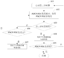
- FIG. 2 is a sequence diagram showing a communication procedure for enabling a primary base station to delete a secondary base station that has successfully transmitted a PDCP PDU according to the present invention
- FIG. 3 is a flow chart showing a method for reporting a downlink data transmission state by a secondary base station to a primary base station according to the present invention
- FIG. 4 is a flow chart showing a method of deleting a PDCP PDU by a primary base station as early as possible according to the present invention
- FIG. 5 is a flowchart illustrating a method of reporting a downlink data transmission state by a secondary base station to a primary base station according to an exemplary embodiment of the present invention
- FIG. 6 is a flowchart illustrating a method of reporting a downlink data transmission state by a secondary base station to a primary base station according to another exemplary embodiment of the present invention
- FIG. 7 is a schematic diagram showing a bitmap included in a downlink data transmission status message
- FIG. 8 is a flowchart illustrating a method of reporting a downlink data transmission state by a secondary base station to a primary base station according to still another exemplary embodiment of the present invention.
- FIG. 9 is a block diagram showing an example structure of a secondary base station according to the present invention.
- Figure 10 is a block diagram showing an example structure of a primary base station according to the present invention.
- the following is an example application of the LTE Rel-12 mobile communication system and its subsequent evolved version. Environment, various embodiments in accordance with the present invention are specifically described. However, it should be noted that the present invention is not limited to the following embodiments, but can be applied to more other wireless communication systems, such as future 5G cellular communication systems.
- the implementation example of the technical solution of the present invention is described herein only for the case where the primary base station and one secondary base station cooperate to provide communication services for the user equipment, the technical solution of the present invention will be equally applicable to the primary base station and one. The above secondary base station cooperates to provide a communication service for the user equipment.
- step 210 the secondary base station transmits a PDCP PDU from the primary base station to the user equipment.
- step 220 the secondary base station sends a downlink data transmission status message to the primary base station through the X2 interface, where the downlink data transmission status message includes a sequence number of at least one successfully transmitted PDCP PDU.
- step 230 the primary base station deletes the PDCP PDU stored in the primary base station according to the received downlink data transmission status message.
- the primary base station determines whether the PDCP PDU and/or the corresponding PDCP SDU indicated in the downlink data transmission status message are still stored locally, if the PDCP PDU and/or the corresponding PDCP SDU indicated in the downlink data transmission status message. Also stored locally, the PDCP PDU and/or the corresponding PDCP SDU are deleted.
- the downlink data transmission status message may only include one PDCP PDU sequence number. In this case, whenever the secondary base station successfully transmits a PDCP PDU from the primary base station, an indication message containing the serial number of the PDCP PDU is sent to the primary base station.
- the secondary base station can determine whether the primary base station is satisfied.
- the condition for transmitting the downlink data transmission status message avoids sending the downlink data transmission status message to the primary base station too frequently.
- the condition that the secondary base station sends the downlink data transmission status message to the primary base station includes at least one of the following: the number of successfully sent PDCP PDUs reaches a set number; the set timer Expired; or the difference between the maximum and minimum sequence numbers of PDCP PDUs that have been successfully sent reaches the set bitmap length.
- the set number of PDCP PDUs, the timer period of the timer, or the bitmap length may be determined according to factors such as a transmission rate of the radio link, a processing capability of the primary base station, and a timing period of a PDCP SDU deletion timer in the primary base station.
- the indication message that the PDCP PDU is successfully sent may include one or more successfully transmitted PDCP PDU sequence numbers and/or bitmaps, and the bitmap length may be a fixed length or a variable length.
- step 310 the secondary base station transmits the PDCP PDU from the primary base station to the user equipment.
- step 320 the secondary base station sends a downlink data transmission status message to the primary base station, where the downlink data transmission status message includes a sequence number of at least one successfully transmitted PDCP PDU.
- the primary base station receives a downlink data transmission status message from the secondary base station, where the downlink data transmission status message includes at least one successfully transmitted.
- the sequence number of the packet data convergence protocol protocol data unit PDCP PDU is the sequence number of the packet data convergence protocol protocol data unit.
- the primary base station deletes the PDCP PDU stored in the primary base station according to the downlink data transmission status message.
- FIG. 5 is a schematic flowchart diagram of an embodiment in which the secondary base station determines the number of successfully transmitted PDCP PDUs and the downlink data transmission status message includes multiple successfully transmitted PDCP PDU sequence numbers.
- the secondary base station sets the SN-number value to 0 and starts the first timer.
- the SN-number indicates the number of PDCP PDUs from the primary base station that have been successfully sent.
- the value of the first timer may be configured in the RLC entity of the secondary base station by using the inter-base station radio resource control message, and may be according to the wireless link.
- the transmission rate, the processing capability of the primary base station, and the timing period of the PDCP SDU deletion timer in the primary base station are determined.
- step 503 the secondary base station determines whether the SN-number value is equal to the set number of PDCP PDUs to be successfully transmitted. If it is equal to the set number of PDCP PDUs to be successfully sent, Then step 504 is performed, otherwise step 506 is performed.
- the secondary base station sends a downlink data transmission status message to the primary base station through the X2 interface, where the downlink data transmission status message includes the sequence number of the successfully transmitted PDCP PDU.
- the downlink data transmission status message further includes the number of PDCP PDUs that have been successfully sent.
- step 505 the secondary base station determines whether the PDCP PDUs from the primary base station have all been transmitted. If the transmission is not completed, step 501 is executed to continue to send the PDCP PDU. End if it has been sent.
- step 506 the secondary base station determines whether the first timer expires. If the first timer expires, step 504 is performed; otherwise, step 507 is performed.
- step 507 the secondary base station determines whether the PDCP PDUs from the primary base station have all been transmitted. If not, the process proceeds to step 502 to continue transmitting the PDCP PDU. If the transmission has been completed, step 508 is executed to send a downlink data transmission status message to the primary base station.
- the secondary base station instructs the primary base station to delete the PDCP PDU whenever the set number of PDCP PDUs is successfully transmitted.
- FIG. 6 is a schematic flowchart diagram of an embodiment in which a secondary base station uses a set timing period as a judgment condition and the downlink data transmission status message includes a plurality of successfully transmitted PDCP PDU sequence numbers.
- the secondary base station starts a second timer.
- the value of the second timer may be configured in an RLC entity of the secondary base station by using an inter-base station radio resource control message, and may be based on a transmission rate of the radio link, a processing capability of the primary base station, and a PDCP SDU deletion timer in the primary base station. Factors such as the timing period are determined.
- step 602 the secondary base station successfully sends a PDCP PDU from the primary base station, and locally stores the serial number of the successfully transmitted PDCP PDU.
- step 603 the secondary base station determines whether the second timer expires. If the second timer expires, step 604 is performed; otherwise, step 606 is performed.
- the secondary base station sends a downlink data transmission status message to the primary base station through the X2 interface.
- the downlink data transmission status message includes a sequence number of the successfully transmitted PDCP PDU.
- the downlink data transmission status message further includes the number of PDCP PDUs that have been successfully sent.
- step 605 the secondary base station determines whether the PDCP PDUs from the primary base station have all been sent. Finished. If the transmission is not completed, step 601 is executed to continue to send the PDCP PDU. End if it has been sent.
- step 606 the secondary base station determines whether the PDCP PDUs from the primary base station have all been transmitted. If the transmission is not completed, step 602 is performed to continue to send the PDCP PDU. If the transmission has been completed, step 607 is executed to send a downlink data transmission status message to the primary base station through the X2 interface.
- the secondary base station instructs the primary base station to delete the PDCP PDU whenever the second timer expires.
- Figure 7 illustrates an example embodiment of a bitmap structure.
- the length of the bitmap shown in Figure 7 can be fixed or variable.
- a bitmap indication bit value of 1 indicates that the corresponding PDCP PDU has been successfully transmitted, and a value of 0 indicates that the corresponding PDCP PDU was not successfully transmitted.
- All the bits corresponding to the PDCP PDUs sent by the primary base station RLC entity have a value of 0.
- 10 PDCP SDUs in the primary base station need to be sent, and PDCP SDUs with sequence numbers 1, 2, 5, 7, and 9 are sent to the RLC entity located at the primary base station, and the sequence is 0, 3, 4, and 6.
- the PDCP SDU of 8 is sent to the RLC entity located at the secondary base station.
- the bitmap in the downlink data transmission status message can be as shown in FIG. 7.
- the sequence numbers of the successfully transmitted PDCP PDUs corresponding to the bitmap shown in FIG. 7 are 4 and 6, respectively.
- the PDCP SDU with sequence number 5 is sent by the RLC entity in the primary base station. Therefore, the value of the bitmap indication bit corresponding to the PDCP PDU with sequence number 5 is zero.
- the PDCP PDU sequence number with sequence number 3 has been listed in the Minimum Sequence Number field of the successfully transmitted SDU in the header of the Downstream Data Transfer Status message and therefore need not be indicated in the bitmap.
- the value of the bitmap indication bit can be any two distinguishable values, including but not limited to ⁇ 0, 1 ⁇ , ⁇ True, False ⁇ .
- the embodiment of the downlink data transmission status message includes a variable length bitmap and the implementation of the downlink data transmission status message shown in FIG. 6 includes multiple successfully transmitted PDCP PDU sequence numbers.
- the flowchart of the example is the same (that is, the condition of determining whether to send the indication message is still determined by the set timing period), but the downlink data transmission status message sent in step 604 includes: the minimum sequence number of the successfully transmitted PDCP PDU and the indication Whether the PDCP PDU following the minimum sequence number PDCP PDU is successfully transmitted by the secondary base station.
- the bitmap is generated according to the sequence number of the successfully transmitted PDCP PDU saved in step 602. Specifically, the bitmap indication bit corresponding to the successfully transmitted PDCP PDU saved locally by the secondary base station is 1, and the other bitmap indication bits are 0.
- the downlink data transmission status message includes a bitmap length degree.
- FIG. 8 shows a flow diagram of an example embodiment of a fixed length bitmap in the downlink data transmission status message.
- the secondary base station starts a third timer and sets the minimum and maximum sequence numbers of the successfully transmitted PDCP PDUs to initial values.
- the value of the third timer may be configured in an RLC entity of the secondary base station by using an inter-base station radio resource control message, and may be based on a transmission rate of the radio link, a processing capability of the primary base station, and a PDCP SDU deletion timer in the primary base station. The timing period and other factors are determined.
- the initial value is a special value different from the serial number of the PDCP PDU to be transmitted, for example, -1, infinity, infinity.
- step 8002 the secondary base station successfully transmits a PDCP PDU from the primary base station, locally stores the sequence number of the successfully transmitted PDCP PDU, and updates the values of the minimum and maximum sequence numbers of the successfully transmitted PDCP PDU.
- the minimum sequence number of the successfully transmitted PDCP PDU is an initial value
- the minimum sequence number of the successfully transmitted PDCP PDU is set to the locally saved successfully transmitted PDCP PDU sequence number. If the minimum sequence number of the successfully transmitted PDCP PDU is greater than the locally saved successfully transmitted PDCP PDU sequence number, the minimum sequence number of the successfully transmitted PDCP PDU is updated to the locally saved successfully sent SDU. serial number. If the maximum sequence number of the successfully transmitted PDCP PDU is the initial value or the maximum sequence number of the successfully transmitted PDCP PDU is smaller than the locally saved successfully transmitted PDCP PDU sequence number, the maximum sequence number of the successfully transmitted PDCP PDU is updated to local save. The PDCP PDU sequence number has been successfully sent.
- step 8003 the secondary base station determines whether the difference between the maximum and minimum sequence numbers of the PDCP PDUs that have been successfully transmitted is equal to the set bitmap length. If it is equal to the set bitmap length, step 8004 is performed, otherwise step 8006 is performed.
- the secondary base station sends a downlink data transmission status message to the primary base station through the X2 interface.
- the downlink data transmission status message includes: a minimum sequence number of the successfully transmitted PDCP PDU, and a bitmap indicating whether the PDCP PDU after the minimum sequence number PDCP PDU is successfully transmitted by the secondary base station.
- the bitmap is generated according to the sequence number of the successfully transmitted PDCP PDU saved in step 8002. Specifically, the bitmap indication bit corresponding to the successfully transmitted PDCP PDU saved locally by the secondary base station is 1, and the other bitmap indication bits are 0.
- step 8005 the secondary base station determines whether the PDCP PDU from the primary base station is all Send it. If not, the process proceeds to step 8001 to continue transmitting the PDCP PDU. End if it has been sent.
- step 8006 the secondary base station determines whether the difference between the maximum and minimum sequence numbers of the PDCP PDUs that have been successfully transmitted is greater than the set bitmap length. If it is greater than the set bitmap length, step 8009 is performed, otherwise step 8007 is performed.
- step 8007 the secondary base station determines whether the third timer expires. If the third timer expires, step 8004 is performed; otherwise, step 8008 is performed.
- step 8008 the secondary base station determines whether the PDCP PDUs from the primary base station have all been transmitted. If not, the process proceeds to step 8002 to continue transmitting the PDCP PDU. End if it has been sent.
- the secondary base station sends a downlink data transmission status message to the primary base station through the X2 interface.
- the downlink data transmission status message includes: a minimum sequence number of the successfully transmitted PDCP PDU, and a bitmap indicating whether the PDCP PDU after the minimum sequence number PDCP PDU is successfully transmitted by the secondary base station.
- the bitmap is generated according to the sequence number of the successfully transmitted PDCP PDU saved in step 8002. Specifically, the bitmap indication bit corresponding to the successfully transmitted PDCP PDU saved locally by the secondary base station is 1, and the other bitmap indication bits are 0.
- the secondary base station also restarts the timer, deletes the locally saved PDCP PDUs other than the recently transmitted PDCP PDU, and sets the maximum and minimum sequence numbers of the successfully transmitted PDCP PDUs.
- the serial number of the PDCP PDU was successfully transmitted recently.
- step 8010 the secondary base station determines whether the PDCP PDUs from the primary base station have all been transmitted. If the transmission is not completed, step 8002 is performed to continue to send the PDCP PDU; otherwise, step 8011 is performed.
- the secondary base station sends a downlink data transmission status message to the primary base station through the X2 interface.
- the downlink data transmission status message includes a minimum sequence number of the successfully transmitted PDCP PDU.
- the downlink data transmission status message further includes a bitmap, where each indicator bit of the bitmap is 0.
- the bitmap length may be configured for the secondary base station RLC entity via the X2 interface by using a radio resource control message between the base stations.
- the RRC message may be sent in a request message sent by the primary base station to the secondary base station to allocate additional resources to the user equipment or sent as an independent message.
- the maximum number of PDCP PDUs that have been successfully sent The difference between the minimum sequence number and the minimum sequence number reaches the set bitmap length, and the secondary base station instructs the primary base station to delete the PDCP PDU.
- FIG. 9 is a block diagram showing the schematic configuration of the secondary base station 900.
- the secondary base station 900 includes a data transmitting unit 910 and a downlink data transmission status message transmitting unit 930.
- the data sending unit 910 is configured to send a PDCP PDU to the user equipment.
- the downlink data transmission status message sending unit 930 is configured to send a downlink data transmission status message to the primary base station, where the downlink data transmission status message includes a sequence number of at least one successfully transmitted PDCP PDU.
- the secondary base station 900 may further include a determining unit 920.
- the determining unit 920 is configured to determine, according to whether the following at least one condition is met, whether to send a downlink data transmission status message to the primary base station: the number of successfully sent PDCP PDUs reaches a set value; the set timer expires; And the difference between the maximum and minimum sequence numbers of the successfully transmitted PDCP PDU is greater than or equal to the set bitmap length.
- FIG. 10 is a block diagram showing the schematic configuration of the primary base station 1000.
- the primary base station 1000 includes a downlink data transmission status message receiving unit 1010 and a PDCP PDU deleting unit 1020.
- the downlink data transmission status message receiving unit is configured to receive a downlink data transmission status message from the secondary base station, where the downlink data transmission status message includes a sequence number of at least one successfully transmitted packet data convergence protocol protocol data unit PDCP PDU.
- the PDCP PDU deleting unit is configured to delete the PDCP PDU stored in the primary base station according to the downlink data transmission status message.
- the primary base station can delete the corresponding PDCP PDU as soon as possible, thereby saving the storage space of the primary base station to receive more service data units from the upper layer.
Landscapes
- Engineering & Computer Science (AREA)
- Computer Networks & Wireless Communication (AREA)
- Signal Processing (AREA)
- Mobile Radio Communication Systems (AREA)
Abstract
Description
Claims (19)
- 一种由辅基站执行的通信方法,包括以下步骤:辅基站向用户设备发送来自主基站的分组数据汇聚协议协议数据单元PDCP PDU;以及辅基站向主基站发送下行数据传输状态消息,所述下行数据传输状态消息包括至少一个已成功发送的PDCP PDU的序列号。
- 根据权利要求1所述的方法,还包括以下步骤:辅基站基于是否满足以下至少一项条件,来判断是否向主基站发送下行数据传输状态消息:已成功发送的PDCP PDU个数达到设定的值;设定的计时器到期;以及已成功发送的PDCP PDU的最大和最小序列号之差大于等于设定的位图长度。
- 根据权利要求1所述的方法,其中,辅基站判断已成功发送的PDCP PDU个数是否达到设定的值;如果达到设定的值,则向主基站发送下行数据传输状态消息;如果未达到设定的值,辅基站进一步判断第一计时器是否到期;如果第一计时器到期,则辅基站向主基站发送下行数据传输状态消息。
- 根据权利要求3所述的方法,其中,如果第一计时器未到期,辅基站进一步判断PDCP PDU是否已全部发送完;如果PDCP PDU已全部发送完,则辅基站向主基站发送下行数据传输状态消息;否则,辅基站不向主基站发送下行数据传输状态消息。
- 根据权利要求3或4所述的方法,其中,所述下行数据传输状态消息包括:已成功发送的PDCP PDU的序列号。
- 根据权利要求3或4所述的方法,其中,所述设定的值和所述第一计时器的计时周期携带在主基站向辅基站发送的为用户设备请求额外资源的请求消息中或通过节点间无线资源配置消息由主基站发送至辅基 站。
- 根据权利要求2所述的方法,其中,辅基站判断第二计时器是否到期;如果第二计时器到期,则辅基站向主基站发送下行数据传输状态消息。
- 根据权利要求7所述的方法,其中,如果第二计时器未到期,辅基站进一步判断PDCP PDU是否已全部发送完;如果PDCP PDU已全部发送完,则辅基站向主基站发送下行数据传输状态消息;否则,辅基站不向主基站发送下行数据传输状态消息。
- 根据权利要求7或8所述的方法,其中,所述下行数据传输状态消息包括:已成功发送的PDCP PDU的序列号;或者已发送成功的PDCPPDU的最小序列号以及指示该最小序列号PDCP PDU之后的PDCP PDU是否由辅基站成功发送的位图。
- 根据权利要求7或8所述的方法,其中,所述第二计时器的计时周期携带在主基站向辅基站发送的为用户设备请求额外资源的请求消息中或通过节点间无线资源配置消息由主基站发送至辅基站。
- 根据权利要求2所述的方法,其中,辅基站判断已成功发送的PDCP PDU的最大和最小序列号之差是否大于等于设定的位图长度;如果所述差大于或等于设定的位图长度,则辅基站向主基站发送下行数据传输状态消息;否则,辅基站进一步判断第三计时器是否到期;如果第三计时器到期,则辅基站向主基站发送下行数据传输状态消息。
- 根据权利要求11所述的方法,其中,如果第三计时器未到期,辅基站进一步判断PDCP PDU是否已全部发送完;如果PDCP PDU已全部发送完,则辅基站向主基站发送下行数据传输状态消息;否则,辅基站不向主基站发送下行数据传输状态消息。
- 根据权利要求11或12所述的方法,其中,所述下行数据传输 状态消息包括:已成功发送的PDCP PDU的最小序列号;以及指示该最小序列号PDCP PDU之后的PDCP PDU是否由辅基站成功发送的位图。
- 根据权利要求11或12所述的方法,其中,如果所述差大于设定的位图长度,则辅基站还判断PDCP PDU是否已全部发送完;如果PDCP PDU已全部发送完,则辅基站向主基站发送下行数据传输状态消息,该下行数据传输状态消息包括最近一次成功发送的PDCP PDU的序列号;否则,辅基站不向主基站发送下行数据传输状态消息。
- 根据权利要求11或12所述的方法,其中,所述位图长度携带在主基站向辅基站发送的为用户设备请求额外资源的请求消息中或通过节点间无线资源配置消息由主基站发送至辅基站。
- 一种辅基站,包括:数据发送单元,用于向用户设备发送来自主基站的分组数据汇聚协议协议数据单元PDCP PDU;以及下行数据传输状态消息发送单元,用于向主基站发送下行数据传输状态消息,所述下行数据传输状态消息包括至少一个已成功发送的PDCP PDU的序列号。
- 根据权利要求16所述的辅基站,还包括:判断单元,基于是否满足以下至少一项条件,来判断是否向主基站发送下行数据传输状态消息:已成功发送的PDCP PDU个数达到设定的值;设定的计时器到期;以及已成功发送的PDCP PDU的最大和最小序列号之差大于等于设定的位图长度。
- 一种由主基站执行的通信方法,包括以下步骤:主基站从辅基站接收下行数据传输状态消息,所述下行数据传输状态消息包括至少一个已成功发送的分组数据汇聚协议协议数据单元PDCP PDU的序列号;以及主基站根据所述下行数据传输状态消息,删除主基站中存储的PDCP PDU。
- 一种主基站,包括:下行数据传输状态消息接收单元,用于从辅基站接收下行数据传输状态消息,所述下行数据传输状态消息包括至少一个已成功发送的分组数据汇聚协议协议数据单元PDCP PDU的序列号;以及PDCP PDU删除单元,用于根据所述下行数据传输状态消息,删除主基站中存储的PDCP PDU。
Priority Applications (3)
| Application Number | Priority Date | Filing Date | Title |
|---|---|---|---|
| JP2016548148A JP2017508364A (ja) | 2014-02-08 | 2015-01-15 | セカンダリ基地局及びマスター基地局によって実行される通信方法、並びに対応する基地局 |
| EP15745793.8A EP3104632B1 (en) | 2014-02-08 | 2015-01-15 | Communication methods executed by auxiliary base station and main base station and corresponding base stations |
| US15/116,761 US10355826B2 (en) | 2014-02-08 | 2015-01-15 | Communication methods performed by secondary base station and master base station and associated base stations |
Applications Claiming Priority (2)
| Application Number | Priority Date | Filing Date | Title |
|---|---|---|---|
| CN201410045528.0A CN104837127B (zh) | 2014-02-08 | 2014-02-08 | 由辅基站和主基站执行的通信方法以及相应的基站 |
| CN201410045528.0 | 2014-02-08 |
Publications (1)
| Publication Number | Publication Date |
|---|---|
| WO2015117537A1 true WO2015117537A1 (zh) | 2015-08-13 |
Family
ID=53777335
Family Applications (1)
| Application Number | Title | Priority Date | Filing Date |
|---|---|---|---|
| PCT/CN2015/070788 WO2015117537A1 (zh) | 2014-02-08 | 2015-01-15 | 由辅基站和主基站执行的通信方法以及相应的基站 |
Country Status (5)
| Country | Link |
|---|---|
| US (1) | US10355826B2 (zh) |
| EP (1) | EP3104632B1 (zh) |
| JP (1) | JP2017508364A (zh) |
| CN (1) | CN104837127B (zh) |
| WO (1) | WO2015117537A1 (zh) |
Cited By (1)
| Publication number | Priority date | Publication date | Assignee | Title |
|---|---|---|---|---|
| CN111133705A (zh) * | 2017-09-27 | 2020-05-08 | 瑞典爱立信有限公司 | 管理下行链路数据传送状态的方法 |
Families Citing this family (16)
| Publication number | Priority date | Publication date | Assignee | Title |
|---|---|---|---|---|
| CN104837163B (zh) * | 2014-02-08 | 2019-10-25 | 夏普株式会社 | 用于删除无线链路控制服务数据单元的方法和基站 |
| CN103888222B (zh) * | 2014-03-21 | 2017-09-15 | 电信科学技术研究院 | 一种数据包处理方法及装置 |
| CN106332175A (zh) * | 2015-07-01 | 2017-01-11 | 中兴通讯股份有限公司 | 一种控制双连接x2状态报告发送的方法、装置及辅基站 |
| WO2017143504A1 (en) * | 2016-02-23 | 2017-08-31 | Telefonaktiebolaget Lm Ericsson (Publ) | Methods used in user equipment and associated ues |
| US11265956B2 (en) * | 2016-05-12 | 2022-03-01 | Ntt Docomo, Inc. | Radio communication system and user device |
| CN107404396B (zh) * | 2016-05-20 | 2019-08-20 | 中国移动通信有限公司研究院 | 一种数据传输方法和装置 |
| CN107889234A (zh) * | 2016-09-30 | 2018-04-06 | 夏普株式会社 | 一种数据转发的方法及其设备 |
| US11558494B2 (en) | 2017-06-19 | 2023-01-17 | Beijing Xiaomi Mobile Software Co., Ltd. | Method and apparatus for processing data, user equipment and computer-readable storage medium |
| WO2018237001A1 (en) * | 2017-06-20 | 2018-12-27 | Intel IP Corporation | DEVICES AND METHODS FOR TRIGGERING FLOW CONTROL AND INFORMATION RETURN |
| WO2018232701A1 (zh) * | 2017-06-22 | 2018-12-27 | 北京小米移动软件有限公司 | 数据传输方法、装置、用户设备及基站 |
| US10448447B2 (en) * | 2017-08-17 | 2019-10-15 | Htc Corporation | Device and method for handling a bearer type change for a radio bearer |
| WO2019137641A1 (en) * | 2018-01-11 | 2019-07-18 | Telefonaktiebolaget Lm Ericsson (Publ) | Submitting a pdcp pdu for transmission |
| CN110932986B (zh) * | 2018-09-20 | 2023-04-07 | 中国电信股份有限公司 | 数据包分流方法、装置及计算机可读存储介质 |
| US11228960B2 (en) * | 2018-11-12 | 2022-01-18 | Nokia Technologies Oy | Efficient signaling in multi-connectivity scenarios |
| US11329924B2 (en) * | 2020-06-03 | 2022-05-10 | Cisco Technology, Inc. | Systems and methods for adapting a WAN egress shaper rate |
| CN115484553A (zh) * | 2021-05-31 | 2022-12-16 | 华为技术有限公司 | 一种通信方法及装置 |
Citations (4)
| Publication number | Priority date | Publication date | Assignee | Title |
|---|---|---|---|---|
| CN101547469A (zh) * | 2008-03-24 | 2009-09-30 | 华为技术有限公司 | 一种发送数据的方法、系统和设备 |
| CN102067663A (zh) * | 2008-06-20 | 2011-05-18 | 高通股份有限公司 | 用于划分无线通信系统中的状态消息(例如,确认)的优先次序的方法和装置 |
| CN102461258A (zh) * | 2009-06-17 | 2012-05-16 | 交互数字专利控股公司 | 使用中继节点进行切换的方法和设备 |
| CN102833802A (zh) * | 2012-08-15 | 2012-12-19 | 电信科学技术研究院 | 一种数据转发方法及设备 |
Family Cites Families (12)
| Publication number | Priority date | Publication date | Assignee | Title |
|---|---|---|---|---|
| EP1343267A3 (en) * | 2002-02-08 | 2005-08-03 | ASUSTeK Computer Inc. | Data transmission confirmation in a wireless communication system |
| KR100802619B1 (ko) * | 2002-11-07 | 2008-02-13 | 엘지전자 주식회사 | 무선 링크 제어 프로토콜에 따르는 수신기에서의 알엘씨데이터 수신 윈도우 처리 방법 |
| CA2689911C (en) * | 2005-01-20 | 2012-07-10 | Nippon Soda Co., Ltd. | Chemical used in chemical solution distributing apparatus |
| TW200803326A (en) * | 2006-06-19 | 2008-01-01 | Innovative Sonic Ltd | Method and apparatus for data framing in a wireless communications system |
| CN101841853A (zh) * | 2009-03-17 | 2010-09-22 | 中兴通讯股份有限公司 | 一种用户设备以及用户设备接收下行数据的方法 |
| US20130088960A1 (en) * | 2011-10-07 | 2013-04-11 | Futurewei Technologies, Inc. | System and Method for Information Delivery with Multiple Point Transmission |
| KR102059042B1 (ko) * | 2013-05-10 | 2020-02-11 | 주식회사 팬택 | 이중연결 시스템에서 멀티 플로우를 고려한 순차적 전달 방법 및 장치 |
| KR102104493B1 (ko) * | 2013-05-10 | 2020-05-04 | 주식회사 팬택 | 이중 연결성을 지원하는 무선 통신 시스템에서 데이터 전송 방법 및 장치 |
| EP2830352A1 (en) * | 2013-07-24 | 2015-01-28 | Panasonic Intellectual Property Corporation of America | Efficient discard mechanism in small cell deployment |
| US9648514B2 (en) * | 2013-08-09 | 2017-05-09 | Blackberry Limited | Method and system for protocol layer enhancements in data offload over small cells |
| JP6230859B2 (ja) * | 2013-09-26 | 2017-11-15 | 株式会社Nttドコモ | 移動通信システム及び無線基地局 |
| JP6262991B2 (ja) * | 2013-10-31 | 2018-01-17 | 株式会社Nttドコモ | ユーザ装置及び方法 |
-
2014
- 2014-02-08 CN CN201410045528.0A patent/CN104837127B/zh active Active
-
2015
- 2015-01-15 WO PCT/CN2015/070788 patent/WO2015117537A1/zh active Application Filing
- 2015-01-15 JP JP2016548148A patent/JP2017508364A/ja active Pending
- 2015-01-15 EP EP15745793.8A patent/EP3104632B1/en active Active
- 2015-01-15 US US15/116,761 patent/US10355826B2/en active Active
Patent Citations (4)
| Publication number | Priority date | Publication date | Assignee | Title |
|---|---|---|---|---|
| CN101547469A (zh) * | 2008-03-24 | 2009-09-30 | 华为技术有限公司 | 一种发送数据的方法、系统和设备 |
| CN102067663A (zh) * | 2008-06-20 | 2011-05-18 | 高通股份有限公司 | 用于划分无线通信系统中的状态消息(例如,确认)的优先次序的方法和装置 |
| CN102461258A (zh) * | 2009-06-17 | 2012-05-16 | 交互数字专利控股公司 | 使用中继节点进行切换的方法和设备 |
| CN102833802A (zh) * | 2012-08-15 | 2012-12-19 | 电信科学技术研究院 | 一种数据转发方法及设备 |
Non-Patent Citations (2)
| Title |
|---|
| "Study on Small Cell Enhancements for E-UTRA and E-UTRAN-Higher layer aspects", TECHNICAL SPECIFICATION GROUP RADIO ACCESS NETWORK, 31 December 2013 (2013-12-31), XP050752647 * |
| See also references of EP3104632A4 * |
Cited By (2)
| Publication number | Priority date | Publication date | Assignee | Title |
|---|---|---|---|---|
| CN111133705A (zh) * | 2017-09-27 | 2020-05-08 | 瑞典爱立信有限公司 | 管理下行链路数据传送状态的方法 |
| CN111133705B (zh) * | 2017-09-27 | 2022-07-01 | 瑞典爱立信有限公司 | 管理下行链路数据传送状态的方法 |
Also Published As
| Publication number | Publication date |
|---|---|
| CN104837127A (zh) | 2015-08-12 |
| CN104837127B (zh) | 2019-12-31 |
| US10355826B2 (en) | 2019-07-16 |
| EP3104632B1 (en) | 2022-11-02 |
| EP3104632A1 (en) | 2016-12-14 |
| US20160352469A1 (en) | 2016-12-01 |
| JP2017508364A (ja) | 2017-03-23 |
| EP3104632A4 (en) | 2017-10-25 |
Similar Documents
| Publication | Publication Date | Title |
|---|---|---|
| WO2015117537A1 (zh) | 由辅基站和主基站执行的通信方法以及相应的基站 | |
| EP3295700B1 (en) | Uplink data splitting | |
| US11601227B2 (en) | Duplication and rlc operation in new radio access technology | |
| WO2015139557A1 (zh) | 分组数据汇聚协议pdcp实体及其执行的方法 | |
| EP2984871B1 (en) | Pdcp operation for dual connection | |
| JP6436436B2 (ja) | スモールセル配備時の効率的な破棄メカニズム | |
| US10277453B2 (en) | Master base station-controlled response to detected failure of radio link between secondary base station and mobile station in dual connectivity wireless networks | |
| WO2015117549A1 (zh) | 用于删除无线链路控制服务数据单元的方法和基站 | |
| EP2999296B1 (en) | Configuring a discard timer | |
| US20130201904A1 (en) | Handover of Connection of User Equipment | |
| EP3393168B1 (en) | User equipment and data reception method, and network node and data transmission method | |
| JP2007527179A (ja) | 無線通信システムの分離型媒体アクセス制御プロトコル構造と、これを用いたデータ送受信方法並びにハンドオーバー方法及びそのシステム | |
| US11665775B2 (en) | Communications device, infrastructure equipment, communications system and methods | |
| WO2015135492A1 (zh) | 缓存状态的上报方法、装置、终端及基站 | |
| US11452128B2 (en) | Method for uplink transmission in a 5G NR system | |
| TW202226879A (zh) | 降低多分支傳輸中封包延遲的方法和裝置 | |
| WO2018059148A1 (zh) | 一种数据转发的方法及其设备 | |
| JP2022543161A (ja) | 通信方法、第1ネットワーク装置、第2ネットワーク装置及び端末装置 | |
| CN117793958A (zh) | 终端装置、基站装置以及方法 | |
| US20150257048A1 (en) | Mobile communication method | |
| EP4304247A1 (en) | Communication method and communication apparatus | |
| WO2018127981A1 (ja) | 無線通信システム、送信装置、受信装置 |
Legal Events
| Date | Code | Title | Description |
|---|---|---|---|
| 121 | Ep: the epo has been informed by wipo that ep was designated in this application |
Ref document number: 15745793 Country of ref document: EP Kind code of ref document: A1 |
|
| ENP | Entry into the national phase |
Ref document number: 2016548148 Country of ref document: JP Kind code of ref document: A |
|
| WWE | Wipo information: entry into national phase |
Ref document number: 15116761 Country of ref document: US |
|
| NENP | Non-entry into the national phase |
Ref country code: DE |
|
| REEP | Request for entry into the european phase |
Ref document number: 2015745793 Country of ref document: EP |
|
| WWE | Wipo information: entry into national phase |
Ref document number: 2015745793 Country of ref document: EP |