WO2015115591A1 - 生物膜濾過装置、淡水化システム、及び、生物膜濾過装置の洗浄方法 - Google Patents
生物膜濾過装置、淡水化システム、及び、生物膜濾過装置の洗浄方法 Download PDFInfo
- Publication number
- WO2015115591A1 WO2015115591A1 PCT/JP2015/052643 JP2015052643W WO2015115591A1 WO 2015115591 A1 WO2015115591 A1 WO 2015115591A1 JP 2015052643 W JP2015052643 W JP 2015052643W WO 2015115591 A1 WO2015115591 A1 WO 2015115591A1
- Authority
- WO
- WIPO (PCT)
- Prior art keywords
- filter medium
- medium layer
- flow rate
- filtration device
- biofilm
- Prior art date
- Legal status (The legal status is an assumption and is not a legal conclusion. Google has not performed a legal analysis and makes no representation as to the accuracy of the status listed.)
- Ceased
Links
Images

Classifications
-
- C—CHEMISTRY; METALLURGY
- C02—TREATMENT OF WATER, WASTE WATER, SEWAGE, OR SLUDGE
- C02F—TREATMENT OF WATER, WASTE WATER, SEWAGE, OR SLUDGE
- C02F3/00—Biological treatment of water, waste water, or sewage
- C02F3/006—Regulation methods for biological treatment
-
- C—CHEMISTRY; METALLURGY
- C02—TREATMENT OF WATER, WASTE WATER, SEWAGE, OR SLUDGE
- C02F—TREATMENT OF WATER, WASTE WATER, SEWAGE, OR SLUDGE
- C02F3/00—Biological treatment of water, waste water, or sewage
- C02F3/02—Aerobic processes
- C02F3/06—Aerobic processes using submerged filters
-
- B—PERFORMING OPERATIONS; TRANSPORTING
- B01—PHYSICAL OR CHEMICAL PROCESSES OR APPARATUS IN GENERAL
- B01D—SEPARATION
- B01D24/00—Filters comprising loose filtering material, i.e. filtering material without any binder between the individual particles or fibres thereof
-
- B—PERFORMING OPERATIONS; TRANSPORTING
- B01—PHYSICAL OR CHEMICAL PROCESSES OR APPARATUS IN GENERAL
- B01D—SEPARATION
- B01D24/00—Filters comprising loose filtering material, i.e. filtering material without any binder between the individual particles or fibres thereof
- B01D24/46—Regenerating the filtering material in the filter
-
- B—PERFORMING OPERATIONS; TRANSPORTING
- B01—PHYSICAL OR CHEMICAL PROCESSES OR APPARATUS IN GENERAL
- B01D—SEPARATION
- B01D29/00—Filters with filtering elements stationary during filtration, e.g. pressure or suction filters, not covered by groups B01D24/00 - B01D27/00; Filtering elements therefor
- B01D29/62—Regenerating the filter material in the filter
- B01D29/66—Regenerating the filter material in the filter by flushing, e.g. counter-current air-bumps
-
- B—PERFORMING OPERATIONS; TRANSPORTING
- B01—PHYSICAL OR CHEMICAL PROCESSES OR APPARATUS IN GENERAL
- B01D—SEPARATION
- B01D36/00—Filter circuits or combinations of filters with other separating devices
-
- C—CHEMISTRY; METALLURGY
- C02—TREATMENT OF WATER, WASTE WATER, SEWAGE, OR SLUDGE
- C02F—TREATMENT OF WATER, WASTE WATER, SEWAGE, OR SLUDGE
- C02F3/00—Biological treatment of water, waste water, or sewage
- C02F3/02—Aerobic processes
- C02F3/08—Aerobic processes using moving contact bodies
- C02F3/085—Fluidized beds
-
- C—CHEMISTRY; METALLURGY
- C02—TREATMENT OF WATER, WASTE WATER, SEWAGE, OR SLUDGE
- C02F—TREATMENT OF WATER, WASTE WATER, SEWAGE, OR SLUDGE
- C02F9/00—Multistage treatment of water, waste water or sewage
-
- C—CHEMISTRY; METALLURGY
- C02—TREATMENT OF WATER, WASTE WATER, SEWAGE, OR SLUDGE
- C02F—TREATMENT OF WATER, WASTE WATER, SEWAGE, OR SLUDGE
- C02F1/00—Treatment of water, waste water, or sewage
- C02F1/44—Treatment of water, waste water, or sewage by dialysis, osmosis or reverse osmosis
- C02F1/441—Treatment of water, waste water, or sewage by dialysis, osmosis or reverse osmosis by reverse osmosis
-
- C—CHEMISTRY; METALLURGY
- C02—TREATMENT OF WATER, WASTE WATER, SEWAGE, OR SLUDGE
- C02F—TREATMENT OF WATER, WASTE WATER, SEWAGE, OR SLUDGE
- C02F3/00—Biological treatment of water, waste water, or sewage
- C02F2003/001—Biological treatment of water, waste water, or sewage using granular carriers or supports for the microorganisms
-
- C—CHEMISTRY; METALLURGY
- C02—TREATMENT OF WATER, WASTE WATER, SEWAGE, OR SLUDGE
- C02F—TREATMENT OF WATER, WASTE WATER, SEWAGE, OR SLUDGE
- C02F2103/00—Nature of the water, waste water, sewage or sludge to be treated
- C02F2103/08—Seawater, e.g. for desalination
-
- C—CHEMISTRY; METALLURGY
- C02—TREATMENT OF WATER, WASTE WATER, SEWAGE, OR SLUDGE
- C02F—TREATMENT OF WATER, WASTE WATER, SEWAGE, OR SLUDGE
- C02F2209/00—Controlling or monitoring parameters in water treatment
- C02F2209/005—Processes using a programmable logic controller [PLC]
-
- C—CHEMISTRY; METALLURGY
- C02—TREATMENT OF WATER, WASTE WATER, SEWAGE, OR SLUDGE
- C02F—TREATMENT OF WATER, WASTE WATER, SEWAGE, OR SLUDGE
- C02F2209/00—Controlling or monitoring parameters in water treatment
- C02F2209/11—Turbidity
-
- C—CHEMISTRY; METALLURGY
- C02—TREATMENT OF WATER, WASTE WATER, SEWAGE, OR SLUDGE
- C02F—TREATMENT OF WATER, WASTE WATER, SEWAGE, OR SLUDGE
- C02F2209/00—Controlling or monitoring parameters in water treatment
- C02F2209/40—Liquid flow rate
-
- C—CHEMISTRY; METALLURGY
- C02—TREATMENT OF WATER, WASTE WATER, SEWAGE, OR SLUDGE
- C02F—TREATMENT OF WATER, WASTE WATER, SEWAGE, OR SLUDGE
- C02F2209/00—Controlling or monitoring parameters in water treatment
- C02F2209/44—Time
-
- C—CHEMISTRY; METALLURGY
- C02—TREATMENT OF WATER, WASTE WATER, SEWAGE, OR SLUDGE
- C02F—TREATMENT OF WATER, WASTE WATER, SEWAGE, OR SLUDGE
- C02F2303/00—Specific treatment goals
- C02F2303/16—Regeneration of sorbents, filters
-
- Y—GENERAL TAGGING OF NEW TECHNOLOGICAL DEVELOPMENTS; GENERAL TAGGING OF CROSS-SECTIONAL TECHNOLOGIES SPANNING OVER SEVERAL SECTIONS OF THE IPC; TECHNICAL SUBJECTS COVERED BY FORMER USPC CROSS-REFERENCE ART COLLECTIONS [XRACs] AND DIGESTS
- Y02—TECHNOLOGIES OR APPLICATIONS FOR MITIGATION OR ADAPTATION AGAINST CLIMATE CHANGE
- Y02A—TECHNOLOGIES FOR ADAPTATION TO CLIMATE CHANGE
- Y02A20/00—Water conservation; Efficient water supply; Efficient water use
- Y02A20/124—Water desalination
- Y02A20/131—Reverse-osmosis
-
- Y—GENERAL TAGGING OF NEW TECHNOLOGICAL DEVELOPMENTS; GENERAL TAGGING OF CROSS-SECTIONAL TECHNOLOGIES SPANNING OVER SEVERAL SECTIONS OF THE IPC; TECHNICAL SUBJECTS COVERED BY FORMER USPC CROSS-REFERENCE ART COLLECTIONS [XRACs] AND DIGESTS
- Y02—TECHNOLOGIES OR APPLICATIONS FOR MITIGATION OR ADAPTATION AGAINST CLIMATE CHANGE
- Y02W—CLIMATE CHANGE MITIGATION TECHNOLOGIES RELATED TO WASTEWATER TREATMENT OR WASTE MANAGEMENT
- Y02W10/00—Technologies for wastewater treatment
- Y02W10/10—Biological treatment of water, waste water, or sewage
Definitions
- the present invention relates to a biofilm filtration device, a desalination system, and a cleaning method for a biofilm filtration device.
- biofilm filtration devices In conventional filtration devices, contaminants mixed in raw water (target liquid) such as seawater and wastewater that flowed in from the upstream side are removed by a biofilm formed in a filter medium layer (sand layer) filled with a filter medium such as sand.
- a biofilm filtration device that discharges the target liquid as a filtrate from the downstream side.
- a backwashing process is performed in which washing water is allowed to flow from the downstream side to the upstream side of the filter medium layer. It is necessary to remove contaminants attached to the biofilm.
- Patent Document 2 discloses a large amount of deposits on the upstream portion (surface layer portion) in the backwashing step by providing a washing water inlet in the middle of the upstream side and the downstream side of the filter medium layer (filler packed layer).
- a biofilm filtration device that cleans and removes only the suspended matter (contaminant) is appropriately disclosed.
- the filtering function of the filter medium layer is reduced by the cleaning, or the cleaning time is reduced. May be longer. For example, if the flow rate of the washing water is so slow that the entire filter medium layer does not fluidize, the cleaning time in the upstream side of the filter medium layer that contains a particularly large amount of contaminants becomes longer, and the time until the filtration of the target liquid is resumed. Becomes longer. Further, for example, if the flow rate is fast enough to fluidize the entire filter medium layer, the biofilm formed on the surface of the filter medium is peeled off, and the filtering function of the filter medium layer is impaired.
- the present invention has been made in view of the above-described circumstances, and a biofilm filtration device capable of efficiently washing a filter medium layer in a short time while suppressing a decrease in filtration function, a desalination system including the same, and a biofilm It aims at providing the washing
- the biofilm filtration device removes contaminants mixed in the target liquid flowing in from the upstream side and discharges the filtrate from the downstream side by the biofilm formed in the filter medium layer.
- a biofilm filtration apparatus comprising: a washing water supply unit that supplies washing water from a downstream side of the filter medium layer; and a control unit that controls a flow rate of the washing water supplied by the washing water supply unit, The control unit supplies the wash water at a first flow rate at which only a predetermined range of layers upstream of the filter medium layer is fluidized, and then supplies the wash water at a second flow rate at which the entire filter medium layer is not fluidized.
- the cleaning method according to another aspect of the present invention is a organism in which contaminants mixed in the target liquid flowing in from the upstream side are removed by the biofilm formed in the filter medium layer, and the filtrate is discharged from the downstream side.
- a cleaning method for a biomembrane filtration device wherein cleaning water is supplied to a membrane filtration device from a downstream side of the filter material layer to wash the filter media layer, and only a predetermined range of layers upstream of the filter media layer flows.
- the upstream range (layer in the predetermined range on the upstream side) of the filter medium layer with a large amount of contaminants attached to the biofilm is determined. Since the fluidization is positively performed, contaminants in the upstream region of the filter medium layer can be efficiently removed in a short time. On the other hand, even if the washing water is supplied to the filter medium layer at the first flow rate, the downstream area of the filter medium layer does not fluidize, but after that, by continuing to supply the wash water at the second flow rate, Contaminants in the range can also be sufficiently removed.
- the biofilm filtration device and the cleaning method thereof fluidization by the wash water is limited to the upstream side of the filter medium layer, and therefore the biofilm peeling accompanying the cleaning is performed on the upstream side of the filter medium layer. Only the range layer is maintained, and the biofilm in the range downstream of the filter media layer is maintained. Therefore, even if washing is performed, the filtration function of the biofilm filtration device can be maintained, and the target liquid can be filtered even immediately after washing. From the above, according to the biofilm filtration device and the cleaning method thereof, the filter membrane layer adheres to the biofilm while suppressing a decrease in the filtration function as compared with the case of supplying wash water at a single flow rate. It is possible to remove the contaminated material efficiently.
- the flow rate of the wash water supplied to the filter medium layer can be appropriately switched from the first flow rate to the second flow rate according to the turbidity of the discharged water, so that the contamination adhering to the biofilm of the filter medium layer Things can be removed more efficiently.
- the biofilm filtration device according to (1) or (3), wherein the filter medium layer is divided into a plurality of layers in a direction from the upstream side toward the downstream side, At least one of the particle size and specific gravity of the uppermost filter medium located on the most upstream side among the plurality of layers is set smaller than the filter medium of the other layer located on the downstream side of the uppermost layer, and the control unit performs the
- the first flow rate is a flow rate for fluidizing only the uppermost layer.
- the first flow rate can be easily set. That is, only the uppermost layer can be fluidized appropriately and easily, and the cleaning time can be shortened. Furthermore, since the uppermost layer is more easily fluidized than other layers, the first flow rate can be kept low. This makes it easier to maintain the biofilm in the filter medium layer even after washing, and also reduces the amount of washing water used for washing.
- the biofilm filtration device is the biofilm filtration device according to any one of (1), (3), and (4), in which the filter medium layer is directed from the upstream side toward the downstream side. Divided into a plurality of layers and provided between the uppermost layer located on the most upstream side of the plurality of layers and another layer adjacent to the downstream side of the uppermost layer, and the uppermost layer and the other layers It is provided with an anti-mixing material that prevents mixing with the layer.
- a desalination system includes the biofilm filtration device according to any one of (1) and (3) to (5), and the biofilm filtration device discharged from the biofilm filtration device.
- the present invention it is possible to efficiently remove contaminants adhering to the biofilm of the filter medium layer while suppressing a decrease in the filtration function of the biofilm filtration apparatus.
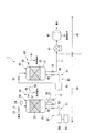
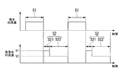
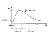
- FIG. 1 It is a figure which shows an example of the desalination system to which the cleaning method of the biofilm filtration apparatus and biofilm filtration apparatus which concern on 1st embodiment of this invention is applied. It is a figure which shows the filtration process implemented in the biofilm filtration apparatus shown in FIG. 1, and a 1st, 2nd washing process. It is a figure which shows the relationship between the washing
- the biofilm filtration apparatus of this embodiment is applied to the desalination system 1 illustrated in FIG.
- the desalination system 1 is a device that desalinates raw water (target liquid) such as seawater and wastewater.
- the desalination system 1 includes a purification device 10 that performs desalination pretreatment (hereinafter referred to as “pretreatment”) and a desalination device 40 that desalinates pretreated seawater (secondary pretreatment seawater described later). And comprising.
- pretreatment desalination pretreatment
- pretreatment desalination device 40 that desalinates pretreated seawater (secondary pretreatment seawater described later). And comprising.
- the purification device 10 and the desalination device 40 are connected by a connection pipe 11.
- the purification device 10 includes two biofilm filtration devices 20 and 30 so as to pretreat seawater in two stages.
- the two biofilm filtration devices 20 and 30 are connected in series by the connecting pipe 12.
- the seawater is first guided to the primary biofilm filtration device 20 (hereinafter referred to as “primary filtration device 20”), and the primary filtration device 20 performs the first stage pretreatment (primary pretreatment).
- the primary pretreated seawater (filtrate) is obtained.
- the primary pretreated seawater is guided to the secondary biofilm filtration device 30 (hereinafter referred to as “secondary filtration device 30”) through the connecting pipe 12.
- the primary pretreated seawater (target liquid) guided to the secondary filtration device 30 becomes secondary pretreated seawater (filtrate) subjected to the second stage pretreatment (secondary pretreatment), and this secondary pretreatment.
- Seawater is supplied to the desalination apparatus 40 through the connection pipe 11. For this reason, contaminants such as turbid components (soil such as sand and mud) mixed in seawater are removed more in the primary filtration device 20 than in the secondary filtration device 30.
- the filtration direction of seawater in the biofilm filtration devices 20 and 30 of the present embodiment is vertically downward as shown in FIG. 1, but is not limited to this, for example, obliquely downward with respect to the vertical direction, It may be horizontal.
- the seawater purified in the primary filtration device 20 and the secondary filtration device 30 is supplied from the purification device 10 to the desalination device 40 through the connection pipe 11.
- the desalination apparatus 40 includes a pump 41 that introduces purified seawater (secondary pretreated seawater), and a reverse osmosis membrane 42 that separates seawater into fresh water and concentrated seawater.
- the primary filtration device 20 forms a filter medium layer 22 formed by filling a particulate filter medium such as sand inside a main body container 21 (filter tower), and forms a biofilm on the surface of the filter medium forming the filter medium layer 22 so that no medicine is used. It is a device that performs pre-processing of notes.
- the filter medium layer 22 of the present embodiment is installed in an intermediate portion of the main body container 21 leaving appropriate space portions on the upstream side and the downstream side thereof.
- the particle size and specific gravity of the filter medium forming the filter medium layer 22 of the present embodiment are set substantially uniform, for example.
- the raw water pipe 13 is connected to the upper part (upstream part) of the main body container 21. Seawater is introduced from the raw water pipe 13 into the upper part of the main body container 21.
- the raw water pipe 13 is provided with an on-off valve (first on-off valve) 23 for opening and closing the raw water pipe 13. Further, an upstream pressure detection unit 24 that detects the pressure of seawater flowing through the raw water pipe 13 is provided in the raw water pipe 13 in the vicinity of the main body container 21. Further, the above-described connecting pipe 12 is connected to the lower part (downstream part) of the main body container 21. An opening / closing valve (second opening / closing valve) 25 for opening and closing the connection pipe 12 is provided in the vicinity of the main body container 21 in the connection pipe 12.
- a downstream pressure detection unit 26 that detects the pressure of the primary pretreatment seawater that is discharged from the main body container 21 and flows through the connection pipe 12, and the primary pretreatment seawater
- a treated water turbidity detector 27 for detecting turbidity is provided.
- the primary filtration device 20 includes a backwash mechanism 50 for removing contaminants attached to the biofilm of the filter medium layer 22.
- the backwash mechanism 50 includes a wash water supply unit 51 that supplies wash water from the downstream side of the filter medium layer 22, a flow rate control unit (control unit) 52 that controls the flow rate of the wash water supplied by the wash water supply unit 51, and . Further, the backwash mechanism 50 includes a wash water discharge unit 53 that discharges wash water (discharged water) that has passed through the filter medium layer 22 from the upstream side.
- the cleaning water supply unit 51 includes a supply unit main body 54 including a supply source of a cleaning water, a pump, and the like, and a cleaning water supply pipe 55 that connects the supply unit main body 54 and the lower part of the main body container 21.
- the washing water discharge unit 53 includes a washing water discharge pipe 57 connected to the upper part of the main body container 21 located above (upstream side) the filter medium layer 22.
- the washing water discharge pipe 57 is provided with an on-off valve (fourth on-off valve) 58 for opening and closing the washing water discharge pipe 57.
- a cleaning water turbidity detection unit (detection unit) 59 that detects the turbidity of the cleaning water (discharged water) discharged from the main body container 21 is provided in the vicinity of the main body container 21 in the cleaning water discharge pipe 57. .
- the washing water turbidity detecting unit 59 may be installed separately from the treated water turbidity detecting unit 27 as shown in the illustrated example.
- the washing water turbidity detecting unit 59 may also be used as a function of the treated water turbidity detecting unit 27.
- the turbidity of the primary pretreated seawater discharged from the main body container 21 by the switching valve and the turbidity of the cleaning water (discharged water) discharged from the main body container 21 are connected to both the connecting pipe 12 and the cleaning drain pipe 57. It may be operated so as to selectively detect the degree.
- the flow rate control unit 52 supplies the washing water at a first flow rate V 1 at which only a predetermined range of the upstream layer of the filter medium layer 22 is fluidized, and then the entire filter medium layer 22 is fluidized. Wash water is supplied at the second flow rate V2.
- the predetermined range on the upstream side is a range in which a large amount of contaminants that are turbid components adhering to the biofilm adhere (for example, the filter medium layer from the upper surface (upstream end face) of the filter medium layer 22 toward the downstream side.
- the first flow velocity V1 and the second flow velocity V2 are flow rates that can obtain a predetermined effective cleaning effect (contaminants can be effectively removed from the filter medium layer 22), and are shown in the following [Equation 1]. Calculated by mathematical formula.
- the second flow rate V2 is a slower flow rate than the first flow rate V1.
- the first flow velocity V1 at which only the upstream portion of the filter medium layer 22 is fluidized is set in consideration of, for example, that the load applied to the downstream portion of the filter medium layer 22 is greater than the load applied to the upstream portion.
- the primary biofilm filtration device 20 is prototyped and a backwash test is performed.
- the flow rate may be adjusted so that only the upstream predetermined layer fluidizes.
- the flow rate control unit 52 switches the flow rate of the washing water from the first flow rate V1 to the second flow rate V2 based on the detection result of the turbidity detected by the washing water turbidity detection unit 59 described above.
- the turbidity detected by the washing water turbidity detection unit 59 becomes the maximum value Tp as shown in FIG. 3 in the state where the washing water is supplied to the filter medium layer 22 at the first flow velocity V1.
- the flow rate control unit 52 switches the flow rate of the washing water from the first flow rate V1 to the second flow rate V2.
- the change in the flow rate of the washing water by the flow rate control unit 52 described above may be performed, for example, by adjusting the output of the pump of the supply unit main body 54, or may be performed by adjusting the opening of the fourth open / close valve 58 (flow rate adjusting valve), for example. It may be broken.
- the primary filtration device 20 further includes a switching control unit (not shown) that switches between a state in which seawater is supplied to the main body container 21 and a state in which cleaning water is supplied to the main body container 21. Based on the detection results of the upstream pressure detection unit 24 and the downstream pressure detection unit 26 and the detection result of the treated water turbidity detection unit 27, the switching control unit of the present embodiment starts from a state in which seawater is supplied to the main body container. Switch to the state where cleaning water is supplied to the main body container.
- the switching control unit determines that the filter medium layer 22 is clogged, and closes the first and second on-off valves 23 and 25 to stop the supply of seawater to the main body container 21.
- the third and fourth on-off valves 56 and 58 are opened to start supplying cleaning water to the main body container 21.
- the switching control unit has a reduced filtration function by the filter medium layer 22.
- the supply of seawater to the main body container 21 is stopped and the supply of cleaning water to the main body container 21 is started.
- the switching control unit It is judged that the filtration function of the layer 22 has been recovered, the third and fourth on-off valves 56 and 58 are closed to stop the supply of the washing water to the main body container 21, and the first and second on-off valves 23 and 25 are turned on. Open and supply of seawater to the main body container 21 is started.
- the secondary filtration device 30 forms a filter medium layer 32 formed by filling the inside of the main body container 31 with a filter medium such as sand, and forms a biofilm on the surface of the filter medium of the filter medium layer 32.
- This is a device that performs pre-treatment of no drug injection. That is, the connecting pipe 12 is connected to the upper part (upstream part) of the main body container 31.
- An opening / closing valve (fifth opening / closing valve) 33 for opening and closing the connection pipe 12 is provided in the vicinity of the main body container 31 in the connection pipe 12.
- connection pipe 11 in the vicinity of the main body container 31 in the connection pipe 12, for example, as in the upstream pressure detection part 24 of the primary filtration device 20, a pressure detection unit (not configured) that detects the pressure of the primary pretreatment seawater flowing through the connection pipe 12. May be provided. Further, the connection pipe 11 described above is connected to the lower part (downstream part) of the main body container 31. An opening / closing valve (sixth opening / closing valve) 35 for opening and closing the connection pipe 11 is provided in the vicinity of the main body container 31 in the connection pipe 11.
- a pressure detection unit (not shown) or a turbidity detection unit similar to the downstream pressure detection unit 26 or the treated water turbidity detection unit 27 of the primary filtration device 20. (Not shown) may be provided.
- the secondary filtration device 30 includes a backwashing mechanism 60 for removing contaminants attached to the biofilm of the filter medium layer 32, similarly to the primary filtration device 20.
- the back washing mechanism 60 of the secondary filtration device 30 includes a washing water supply unit 61 and a washing water discharge unit 63 similar to the primary filtration device 20.
- the cleaning water supply unit 61 includes a supply unit main body 64 including a supply source of a cleaning water, a pump, and the like, and a cleaning water supply pipe 65 that connects the supply unit main body 64 and the lower part of the main body container 31.
- the flow rate of the washing water supplied from the supply unit main body 64 to the filter medium layer 32 is constant, and is set to a flow rate at which the entire filter medium layer 32 is not fluidized.
- the cleaning water supply pipe 65 is provided with an opening / closing valve (seventh opening / closing valve) 66 for opening and closing the cleaning water supply pipe 65.
- the washing water discharge part 63 includes a washing water discharge pipe 67 connected to the upper part of the main body container 31 located above (upstream side) the filter medium layer 32 as in the primary filtration device 20.
- the washing water discharge pipe 67 is provided with an opening / closing valve (eighth opening / closing valve) 68 for opening and closing the washing water discharge pipe 67.
- a turbidity detection unit (not shown) similar to the cleaning water turbidity detection unit 59 of the primary filtration device 20 may be provided in the vicinity of the main body container 21 in the cleaning water discharge pipe 67, for example.
- the secondary filtration device 30 also includes a switching control unit (not shown) similar to the primary filtration device 20.
- the seawater is sequentially passed through the primary filtration device 20 and the secondary filtration device 30 to remove contaminants such as turbid components contained in the seawater (see the filtration step S ⁇ b> 1 and FIG. 2).
- the filtration step S1 contaminants are removed from the seawater by adhering to the biofilms formed on the filter media layers 22 and 32 of the filtration devices 20 and 30, respectively.
- a large amount of contaminants in the sea water is removed in the upstream range (upstream predetermined layer) than the downstream range of the filter media layers 22 and 32.
- each filtration apparatus 20 and 30 detects the detection result of the upstream pressure detection part 24 and the downstream pressure detection part 26, and the detection result of the treated water turbidity detection part 27. Is monitoring.
- the switching control unit closes the first and second on-off valves 23 and 25 to supply seawater to the main body container 21. While stopping, the 3rd and 4th on-off valves 56 and 58 are opened, and supply of the washing water to the main body container 21 is started. As a result, a cleaning step S2 (see FIG. 2) for cleaning the filter medium layer 22 by supplying the cleaning liquid from the downstream side of the filter medium layer 22 is started.
- the cleaning step S2 cleaning method
- the first cleaning step S21 and the second cleaning step S22 are sequentially performed to remove contaminants attached to the biofilm of the filter medium layer 22 from the filter medium layer 22. .
- washing water is supplied at a first flow velocity V1 at which only a predetermined range of layers upstream of the filter medium layer 22 is fluidized.
- the flow rate controller 52 controls the flow rate of the washing water to the first flow rate V1.
- the upstream region of the filter medium layer 22 with a large amount of contaminants adhering to the biofilm is actively fluidized, so that the contaminants in the upstream region of the filter medium layer 22 are efficiently collected in a short time. Removed.
- the downstream range of the filter medium layer 22 with less contaminants attached to the biofilm is not fluidized, but the contaminants in the downstream range of the filter medium layer 22 are also removed little by little.
- the wash water (discharged water) that has passed through the filter medium layer 22 at the first flow velocity V1 is discharged to the wash water discharge pipe 57 from the upstream side of the filter medium layer 22 in a state including the removed contaminants.
- cleaning process S21 as shown in FIG. 3, the contaminant contained in discharge water increases as time passes, and the turbidity of discharge water rises. Then, the turbidity of the discharged water reaches the maximum value Tp and then starts to decrease.
- the turbidity of the discharged water is detected (detection step).
- the detection process of this embodiment is performed by the washing water turbidity detection unit 59.
- the above-described first cleaning step S21 is switched to the second cleaning step S22 described later (switching step) based on the turbidity detection result in the detection step.
- the switching process of the present embodiment is performed by the flow rate controller 52.
- the flow rate control unit 52 changes the flow rate of the washing water from the first flow rate V1 to the first flow rate. Switch to dual flow rate V2.
- the 2nd washing process S22 which supplies washing water with the 2nd flow velocity V2 in which the whole filter media layer 22 does not fluidize is carried out.
- the second washing step S22 since the flow rate of the washing water passing through the filter medium layer 22 is smaller than that in the first washing process S21, the efficiency of removing contaminants from the filter medium layer 22 is lower than that in the first washing process S21. Since washing water flows through the entire filter medium layer 22, contaminants are gradually removed from the filter medium layer 22. Thereby, in 2nd washing
- the cleaning method for the secondary filtration device 30 can be performed in the same manner as the cleaning method for the primary filtration device, except for the first cleaning step S21 and the switching step described above, description thereof is omitted.
- the filter medium layer 22 of the primary filtration device 20 when the filter medium layer 22 of the primary filtration device 20 is washed, first, the range on the upstream side of the filter medium layer 22 having a large amount of contaminants attached to the biofilm is positively increased. Therefore, the contaminants in the upstream region of the filter medium layer 22 can be efficiently removed in a short time. On the other hand, even if the washing water is supplied to the filter medium layer at the first flow rate V1, the downstream area of the filter medium layer 22 does not fluidize, but thereafter, since the wash water is continuously supplied at the second flow rate V2, the filter medium layer 22 Contaminants in the downstream area can be sufficiently removed.
- fluidization by the washing water is limited to the upstream side of the filter medium layer 22, and therefore, the biofilm is peeled only by a predetermined range on the upstream side of the filter medium layer 22.
- the biofilm in the range downstream of the filter medium layer 22 is maintained.
- the upstream range of the filter medium layer 22 is located on the inlet side into which seawater flows, the biofilm in the upstream area of the filter medium layer 22 can be regenerated in a short time by restarting the filtration step S1. It is. Therefore, even if it wash
- the washing water compared to the case where the washing water is supplied at a single flow rate, it adheres to the biofilm of the filter medium layer 22 while suppressing a decrease in the filtration function of the primary filtration device 20.
- the removed contaminants can be removed efficiently.
- wash water is supplied with a single flow rate. It is also possible to reduce the amount of cleaning water used compared to the case of supplying.
- the flow rate of the wash water supplied to the filter medium layer 22 is changed from the first flow rate V1 to the second flow rate V2 according to the turbidity of the discharged water discharged from the upstream side of the filter medium layer 22. Since it can switch appropriately, the contaminant adhering to the biofilm of the filter medium layer 22 can be removed more efficiently.
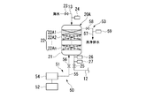
- the primary filtration device 20 ⁇ / b> A of the present embodiment is provided in the desalination system 1 (see FIG. 1) instead of the primary filtration device 20 of the first embodiment.
- the primary filtration device 20 ⁇ / b> A of the present embodiment includes a main body container 21, a filter medium layer 22, and a backwash mechanism 50 similar to those of the first embodiment.
- the filter medium layer 22 of the present embodiment is divided into a plurality of layers 22A1 to 22An in the direction from the upstream side to the downstream side.
- At least one of the particle size and specific gravity of the filter medium forming the uppermost layer 22A1 located on the most upstream side is set smaller than the other layers 22A2 to 22An located on the downstream side of the uppermost layer 22A1.
- the particle size and specific gravity of the filter media forming the other layers 22A2 to 22An may be different from each other or may be equivalent.
- the particle size and specific gravity of the filter medium in the other layers 22A2 to 22An may be set to be equal or larger toward the downstream side of the filter medium layer 22, for example.
- the first flow velocity V1 (see FIG. 2) by the flow velocity control unit 52 is set so as to fluidize only the uppermost layer 22A1, but the particle size and specific gravity of the filter medium in the uppermost layer 22A1 are the above-described values.
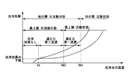
- the horizontal axis indicates the flow rate of the cleaning water
- the vertical axis indicates the cleaning effect (back cleaning effect) corresponding to the flow rate of the cleaning water.
- the cleaning effect indicates that the higher the numerical value, the more efficiently the filter medium layer 22 is cleaned.
- the “lower limit of the cleaning effect” indicates a boundary whether or not an effective cleaning effect is obtained in the primary filtration device 20A.
- the characteristic of the cleaning effect is uniquely determined according to the particle size and specific gravity of the filter medium constituting the filter medium layer 22. That is, the relationship between the flow rate of cleaning water and the cleaning effect in the case of the uppermost layer 22A1 is determined as shown by the solid line in the graph of FIG. Further, the relationship between the flow rate of the cleaning water and the cleaning effect in the case of the other layers 22A2 to 22An is determined as indicated by the broken line in the graph.
- the flow rate of the washing water corresponding to the flow / non-flow boundary of the uppermost layer 22A1 (boundary flow velocity Vm2 of the uppermost layer 22A1)
- the flow / non-flow boundary of the other layers Corresponding cleaning water flow rate (boundary flow rate Vm1 of the other layers 22A2 to 22An) and cleaning water flow rate corresponding to the “lower limit of cleaning effect” (lower limit flow rate Vs) can be easily obtained. Since the particle size and specific gravity of the other layers 22A2 to 22An are larger than those of the uppermost layer 22A1, the boundary flow velocity Vm1 of the other layers 22A2 to 22An is larger than the boundary flow velocity Vm2 of the uppermost layer 22A1.
- the appropriate first flow rate V1 of the washing water may be set in a range not less than the boundary flow velocity Vm2 of the uppermost layer 22A1 and not more than the boundary flow velocity Vm1 of the other layers 22A2 to 22An.
- the appropriate second flow velocity V2 of the cleaning water may be set in a range that is not less than the lower limit flow velocity Vs and less than the boundary flow velocity Vm2 of the uppermost layer 22A1.
- the primary filtration device 20A of the present embodiment there are the same effects as in the first embodiment. Further, since the uppermost layer 22A1 is more easily fluidized than the other layers 22A2 to 22An by the flow of the washing water, the first flow velocity V1 can be easily set. That is, only the uppermost layer 22A1 can be fluidized appropriately and easily, and the cleaning time can be shortened. Further, since the uppermost layer 22A1 is more easily fluidized than the other layers 22A2 to 22An, the first flow velocity V1 can be kept low. Thereby, even if the filter medium layer 22 is washed, it becomes easier to maintain the biofilm on the filter medium layer 22, and the amount of washing water used for washing can be reduced.
- the primary filtration apparatus 20B of this embodiment is provided in the desalination system 1 (refer FIG. 1) instead of the primary filtration apparatus 20 of 1st Embodiment.
- the primary filtration device 20B of the present embodiment includes a main body container 21, a filter medium layer 22, and a backwash mechanism 50 similar to those of the first embodiment.
- the filter medium layer 22 of this embodiment is divided into a plurality of (two in the illustrated example) layers 22B1 and 22B2 in the direction from the upstream side toward the downstream side.
- the particle size and specific gravity of the filter medium forming the uppermost layer 22B1 located on the most upstream side among the plurality of layers 22B1 and 22B2 may be set smaller than the other layers 22B2, for example, as in the second embodiment.
- the primary filtration device 20B of the present embodiment includes a mixing preventing material 28 provided between the uppermost layer 22B1 and another layer 22B2 adjacent to the downstream side.
- the mixing preventing material 28 prevents mixing of the uppermost layer 22B1 and the other layer 22B2, and is, for example, a net-like member that allows seawater or filtered water to pass therethrough.
- the primary filtration device 20B of this embodiment there are the same effects as in the first embodiment. Further, since mixing with the uppermost layer 22B1 and the other layer 22B2 is prevented, by supplying the cleaning water at the first flow velocity V1 (see FIG. 2), only the uppermost layer 22B1 is surely fluidized, and the other layers It can suppress reliably that 22B2 fluidizes.
- the flow rate control unit 52 of the above embodiment switches the flow rate of the wash water based on the turbidity detection result by the wash water turbidity detection unit 59, but after switching from the filtration step S1 to the wash step S2, for example.
- the flow rate of the washing water may be automatically switched after a predetermined time has elapsed.
- the flow rate control of the washing water by the flow rate control unit 52 is not limited to being applied only to the first filtration device 20, and may be applied to the second filtration device 30, for example.
- the biofilm filtration device and the cleaning method thereof of the present invention are preferably applied to the first stage or those close to the first stage, but are not particularly limited.
- the biofilm filtration device and the cleaning method thereof according to the present invention are not limited to being applied to the desalination system 1, but may be applied to various systems that need to remove contaminants mixed in raw water (target liquid). Is possible.
- the present invention it is possible to efficiently remove contaminants adhering to the biofilm of the filter medium layer while suppressing a decrease in the filtration function of the biofilm filtration apparatus.
Landscapes
- Life Sciences & Earth Sciences (AREA)
- Chemical & Material Sciences (AREA)
- Organic Chemistry (AREA)
- Hydrology & Water Resources (AREA)
- Engineering & Computer Science (AREA)
- Environmental & Geological Engineering (AREA)
- Water Supply & Treatment (AREA)
- Biodiversity & Conservation Biology (AREA)
- Microbiology (AREA)
- Chemical Kinetics & Catalysis (AREA)
- Health & Medical Sciences (AREA)
- Molecular Biology (AREA)
- Biological Treatment Of Waste Water (AREA)
- Filtration Of Liquid (AREA)
- Separation Using Semi-Permeable Membranes (AREA)
Abstract
Description
本願は、2014年1月31日に日本に出願された特願2014-016963号について優先権を主張し、その内容をここに援用する。
この種の生物膜濾過装置では、例えば特許文献1のように、所定の運転時間(濾過時間)が経過した後に、濾材層の下流側から上流側に洗浄水を流す逆洗工程を実施して、生物膜に付着した混入物を除去する必要がある。
特許文献2の生物膜濾過装置では、濾材層のうち上流側の範囲のみを洗浄するため、洗浄水の流速が速くても、濾材層の下流側の範囲における生物膜が剥離することはない。しかしながら、下流側の範囲の洗浄が実施されないため、濾材層による濾過機能は低下してしまう。
以上のことから、上記生物膜濾過装置及びその洗浄方法によれば、単一の流速で洗浄水を供給する場合と比較して、濾過機能の低下を抑制しつつ、濾材層の生物膜に付着した混入物を効率よく除去することが可能である。
さらに、最上層が他の層よりも流動化しやすいことで、第一流速を低く抑えることができる。これにより、洗浄しても濾材層に生物膜をより維持しやすくなると共に、洗浄に使用する洗浄水の量を低減することも可能となる。
以下、図1~3を参照して本発明の第一実施形態について説明する。
本実施形態の生物膜濾過装置は、図1に例示する淡水化システム1に適用される。淡水化システム1は、海水や廃水等の原水(対象液)を淡水化する装置である。淡水化システム1は、海水を淡水化前処理(以下、「前処理」と呼ぶ)する浄化装置10と、前処理後の海水(後述する二次前処理海水)を淡水化する淡水化装置40と、を備える。浄化装置10及び淡水化装置40は、接続配管11によって接続されている。
浄化装置10は、海水を二段階で前処理するように、二つの生物膜濾過装置20,30を備える。二つの生物膜濾過装置20,30は、連結配管12によって直列に接続されている。
この浄化装置10において、海水は、はじめに、一次生物膜濾過装置20(以下、「一次濾過装置20」と呼ぶ。)に導かれ、一次濾過装置20において第一段階の前処理(一次前処理)が実施されることで一次前処理海水(濾過液)となる。一次前処理海水は、連結配管12を通って二次生物膜濾過装置30(以下、「二次濾過装置30」と呼ぶ。)に導かれる。二次濾過装置30に導かれた一次前処理海水(対象液)は、第二段階の前処理(二次前処理)がなされた二次前処理海水(濾過液)となり、この二次前処理海水が接続配管11を通って淡水化装置40に供給される。このため、海水に混入する濁質成分(砂や泥等の汚れ分)等の混入物は、二次濾過装置30よりも一次濾過装置20において多く除去される。
本実施形態の生物膜濾過装置20,30における海水の濾過処理方向は、図1のように鉛直方向下向きとなっているが、これに限ることはなく、例えば鉛直方向に対して斜め下向きや、水平方向となっていてもよい。
本体容器21の上部(上流側部分)には、原水配管13が接続されている。海水は、原水配管13から本体容器21の上部に導入される。原水配管13には、これを開閉する開閉弁(第一開閉弁)23が設けられる。また、原水配管13のうち本体容器21の近傍には、原水配管13を流れる海水の圧力を検出する上流側圧力検出部24が設けられる。
さらに、本体容器21の下部(下流側部分)には、前述した連結配管12が接続されている。連結配管12のうち本体容器21の近傍には、連結配管12を開閉する開閉弁(第二開閉弁)25設けられる。また、連結配管12のうち本体容器21の近傍には、本体容器21から排出されて連結配管12を流れる一次前処理海水の圧力を検出する下流側圧力検出部26、及び、一次前処理海水の濁度を検出する処理水濁度検出部27が設けられる。
洗浄水供給部51は、洗浄水の供給源やポンプ等を含む供給部本体54と、供給部本体54と本体容器21の下部とを接続する洗浄水供給管55と、を備える。洗浄供給管のうち本体容器21の下部近傍には、洗浄供給管を開閉する開閉弁(第三開閉弁)56設けられる。
洗浄水排出部53は、濾材層22よりも上方(上流側)に位置する本体容器21の上部に接続された洗浄水排出管57を備える。洗浄水排出管57には、これを開閉する開閉弁(第四開閉弁)58が設けられる。また、洗浄水排出管57のうち本体容器21の近傍には、本体容器21から排出された洗浄水(排出水)の濁度を検出する洗浄水濁度検出部(検出部)59が設けられる。なお、洗浄水濁度検出部59は、図示例のように処理水濁度検出部27と個別に設置されてもよいし、例えば、処理水濁度検出部27の機能を兼用するように、連結配管12、洗浄排水管57の両方に配管されると共に、切換弁によって本体容器21から排出された一次前処理海水の濁度と、本体容器21から排出された洗浄水(排出水)の濁度と、を選択的に検出するように運用してもよい。

すなわち、本体容器31の上部(上流側部分)には、連結配管12が接続されている。
連結配管12のうち本体容器31の近傍には、連結配管12を開閉する開閉弁(第五開閉弁)33が設けられている。さらに、連結配管12のうち本体容器31の近傍には、例えば一次濾過装置20の上流側圧力検出部24と同様に、連結配管12を流れる一次前処理海水の圧力を検出する圧力検出部(不図示)が設けられてもよい。また、本体容器31の下部(下流側部分)には、前述した接続配管11が接続されている。接続配管11のうち本体容器31の近傍には、接続配管11を開閉する開閉弁(第六開閉弁)35が設けられている。さらに、接続配管11のうち本体容器31の近傍には、例えば一次濾過装置20の下流側圧力検出部26や処理水濁度検出部27と同様の圧力検出部(不図示)や濁度検出部(不図示)が設けられてもよい。
洗浄水供給部61は、洗浄水の供給源やポンプ等を含む供給部本体64と、供給部本体64と本体容器31の下部とを接続する洗浄水供給管65と、を備える。供給部本体64から濾材層32に供給される洗浄水の流速は、一定であり、濾材層32全体が流動化しない流速に設定される。洗浄水供給管65には、これを開閉する開閉弁(第七開閉弁)66が設けられる。
また、二次濾過装置30は、一次濾過装置20と同様の切換制御部(不図示)も備える。
浄化装置10では、海水を一次濾過装置20、二次濾過装置30に順番に通過させることで、海水に含まれる濁質成分等の混入物を除去する(濾過工程S1、図2参照)。濾過工程S1では、混入物が各濾過装置20,30の濾材層22,32に形成された生物膜に付着することで海水から除去される。海水中の混入物は濾材層22,32の下流側の範囲よりも上流側の範囲(上流側の所定範囲の層)において多く除去される。また、濾過工程S1では、各濾過装置20,30の切換制御部(不図示)が上流側圧力検出部24及び下流側圧力検出部26の検出結果や、処理水濁度検出部27の検出結果を監視している。
そして、第一流速V1で濾材層22を通過した洗浄水(排出水)は、除去された混入物を含んだ状態で濾材層22の上流側から洗浄水排出管57に排出される。このため、第一洗浄工程S21では、図3に示すように、時間が経過するにつれて排出水に含まれる混入物が多くなり、排出水の濁度が上昇する。そして、排出水の濁度は最大値Tpに到達し、その後低下しはじめる。
本実施形態の切換工程では、図2,3に示すように、濁度が最大値Tpから第一所定レベルだけ低下した時点で、流速制御部52が洗浄水の流速を第一流速V1から第二流速V2に切り換える。これにより、濾材層22全体が流動化しない第二流速V2で洗浄水を供給する第二洗浄工程S22が実施される。
そして、排出水の濁度が第二所定レベル以下となった際には、図2に示すように、第二洗浄工程S22が停止され、前述した濾過工程S1が再開される。本実施形態では、第二洗浄工程S22から濾過工程S1への切換が、切換制御部によって実施される。これら濾過工程S1、第一洗浄工程S21、第二洗浄工程S22は、繰り返し順番に実施される。
また、本実施形態によれば、第二洗浄工程S22における洗浄水の第二流速V2は、第一洗浄工程S21における洗浄水の第一流速V1よりも低いため、単一の流速で洗浄水を供給する場合と比較して、洗浄水の使用量を低減することも可能となる。
さらに、本実施形態によれば、濾材層22の上流側から排出される排出水の濁度に応じて、濾材層22に供給される洗浄水の流速を第一流速V1から第二流速V2に適切に切り換えることができるため、濾材層22の生物膜に付着した混入物をさらに効率的に除去できる。
次に、本発明の第二実施形態について、図4,5を参照して、第一実施形態との相違点を中心に説明する。なお、第一実施形態と共通する構成については、同一符号を付し、その説明を省略する。
本実施形態の一次濾過装置20Aは、第一実施形態と同様の本体容器21、濾材層22、逆洗機構50を備える。ただし、本実施形態の濾材層22は、上流側から下流側に向かう方向に複数の層22A1~22Anに分割されている。図示例の濾材層22は、n個(n=2,3,4,…)の層22A1~22Anに分割されている。複数の層22A1~22Anのうち最も上流側に位置する最上層22A1をなす濾材の粒径及び比重の少なくとも一方は、最上層22A1の下流側に位置する他の層22A2~22Anよりも小さく設定されている。他の層22A2~22Anをなす濾材の粒径や比重は、互いに異なっていてもよいし、同等であってもよい。他の層22A2~22Anにおける濾材の粒径や比重は、例えば濾材層22の下流側に向かうにしたがって同等もしくは大きくなるように設定されてもよい。
洗浄効果の特性は、濾材層22を構成する濾材の粒径や比重に応じて一義的に決まる。
すなわち、最上層22A1の場合の洗浄水の流速と洗浄効果との関係は、図5のグラフの実線のように決まる。また、他の層22A2~22Anの場合の洗浄水の流速と洗浄効果との関係は、同グラフの破線のように決まる。
したがって、適正な洗浄水の第一流速V1は、最上層22A1の境界流速Vm2以上、かつ、他の層22A2~22Anの境界流速Vm1以下の範囲で設定されればよい。また、適正な洗浄水の第二流速V2(図2参照)は、下限流速Vs以上、かつ、最上層22A1の境界流速Vm2未満の範囲で設定されればよい。
また、洗浄水の流れによって最上層22A1が他の層22A2~22Anよりも流動化しやすいため、第一流速V1の設定が容易となる。すなわち、最上層22A1のみを適切かつ簡単に流動化させることができ、洗浄時間の短縮化を図ることが可能となる。また、最上層22A1が他の層22A2~22Anよりも流動化しやすいことで、第一流速V1を低く抑えることができる。これにより、濾材層22を洗浄しても、濾材層22に生物膜をより維持しやすくなると共に、洗浄に使用する洗浄水の量を低減することも可能となる。
次に、本発明の第三実施形態について、図6を参照して、第一実施形態との相違点を中心に説明する。なお、第一実施形態と共通する構成については、同一符号を付し、その説明を省略する。
複数の層22B1,22B2のうち最も上流側に位置する最上層22B1をなす濾材の粒径や比重は、例えば第二実施形態の場合と同様に、他の層22B2よりも小さく設定されてもよいし、例えば他の層22B2をなす濾材の粒径や比重と同等であってもよい。
また、本実施形態の一次濾過装置20Bは、最上層22B1と下流側に隣接する他の層22B2との間に設けられる混合防止材28を備える。混合防止材28は、最上層22B1と他の層22B2との混合を防ぐものであり、例えば海水や濾過水を通す網状部材である。
また、最上層22B1及び他の層22B2との混合が防止されるため、第一流速V1(図2参照)で洗浄水を供給することで確実に最上層22B1のみを流動化させ、他の層22B2が流動化することを確実に抑えることができる。
例えば、上記実施形態の流速制御部52は、洗浄水濁度検出部59による濁度の検出結果に基づいて、洗浄水の流速を切り換えるが、例えば濾過工程S1から洗浄工程S2に切り換えられた後、所定時間経過した後に自動的に洗浄水の流速を切り換えてもよい。
また、流速制御部52による洗浄水の流速制御は、第一濾過装置20のみに適用されることに限らず、例えば第二濾過装置30に適用されてもよい。
また、本発明の生物膜濾過装置及びその洗浄方法は、淡水化システム1に適用されることに限らず、原水(対象液)に混入する混入物を除去する必要がある各種システムに適用することが可能である。
20,20A,20B…一次生物膜濾過装置、
22…濾材層、
22A1,22B1…最上層、
22A2~22An,22B2…他の層、
28…混合防止材、
30…二次生物膜濾過装置、
40…淡水化装置、
51…洗浄水供給部、
52…流速制御部(制御部)、
59…洗浄水濁度検出部(検出部)、
S11…第一洗浄工程、
S22…第二洗浄工程、
V1…第一流速、
V2…第二流速
Claims (6)
- 濾材層に形成された生物膜により、上流側から流入させた対象液に混入する混入物を除去して下流側から濾過液を排出させる生物膜濾過装置であって、
前記濾材層の下流側から洗浄水を供給する洗浄水供給部と、
該洗浄水供給部によって供給される洗浄水の流速を制御する制御部と、を備え、
該制御部は、前記濾材層の上流側の所定範囲の層のみが流動化する第一流速で洗浄水を供給した後に、前記濾材層全体が流動化しない第二流速で洗浄水を供給することを特徴とする生物膜濾過装置。 - 前記洗浄水供給部によって供給された洗浄水の前記濾材層の上流側からの排出水の濁度を検出する検出部を備え、
前記制御部が、前記検出部による濁度の検出結果に基づいて前記洗浄水の流速を切り換えることを特徴とする請求項1に記載の生物膜濾過装置。 - 前記濾材層が、上流側から下流側に向かう方向に複数の層に分割され、
前記複数の層のうち最も上流側に位置する最上層の濾材の粒径及び比重の少なくとも一方が、前記最上層の下流側に位置する他の層の濾材よりも小さく設定され、
前記制御部による前記第一流速が、前記最上層のみを流動化させる流速であることを特徴とする請求項1又は請求項2に記載の生物膜濾過装置。 - 前記濾材層が、上流側から下流側に向かう方向に複数の層に分割され、
前記複数の層のうち最も上流側に位置する最上層と、該最上層の下流側に隣接する他の層との間に設けられ、前記最上層と前記他の層との混合を防ぐ混合防止材を備えることを特徴とする請求項1から請求項3のいずれか一項に記載の生物膜濾過装置。 - 請求項1から請求項4のいずれか一項に記載の生物膜濾過装置と、
該生物膜濾過装置から排出された前記濾過液を淡水化する淡水化装置と、を備えることを特徴とする淡水化システム。 - 濾材層に形成された生物膜により、上流側から流入させた対象液に混入する混入物を除去して下流側から濾過液を排出させる生物膜濾過装置に対し、前記濾材層の下流側から洗浄水を供給して前記濾材層を洗浄する生物膜濾過装置の洗浄方法であって、
前記濾材層の上流側の所定範囲の層のみが流動化する第一流速で前記洗浄水を供給する第一洗浄工程と、
該第一洗浄工程の後に、前記濾材層全体が流動化しない第二流速で前記洗浄水を供給する第二洗浄工程と、
を含むことを特徴とする生物膜濾過装置の洗浄方法。
Priority Applications (4)
| Application Number | Priority Date | Filing Date | Title |
|---|---|---|---|
| ES201690032A ES2589593B1 (es) | 2014-01-31 | 2015-01-30 | Dispositivo de filtrado de biopelícula, sistema de desalinización y procedimiento de limpieza del dispositivo de filtrado de biopelícula |
| AU2015211762A AU2015211762A1 (en) | 2014-01-31 | 2015-01-30 | Biofilm filter device, desalination system, and biofilm filter device cleansing method |
| SG11201605720UA SG11201605720UA (en) | 2014-01-31 | 2015-01-30 | Biofilm filter device, desalination system, and biofilm filter device cleansing method |
| US15/112,582 US20160332901A1 (en) | 2014-01-31 | 2015-01-30 | Biofilm filter device, desalination system, and biofilm filter device cleaning method |
Applications Claiming Priority (2)
| Application Number | Priority Date | Filing Date | Title |
|---|---|---|---|
| JP2014-016963 | 2014-01-31 | ||
| JP2014016963A JP2015142885A (ja) | 2014-01-31 | 2014-01-31 | 生物膜濾過装置、淡水化システム、及び、生物膜濾過装置の洗浄方法 |
Publications (1)
| Publication Number | Publication Date |
|---|---|
| WO2015115591A1 true WO2015115591A1 (ja) | 2015-08-06 |
Family
ID=53757159
Family Applications (1)
| Application Number | Title | Priority Date | Filing Date |
|---|---|---|---|
| PCT/JP2015/052643 Ceased WO2015115591A1 (ja) | 2014-01-31 | 2015-01-30 | 生物膜濾過装置、淡水化システム、及び、生物膜濾過装置の洗浄方法 |
Country Status (6)
| Country | Link |
|---|---|
| US (1) | US20160332901A1 (ja) |
| JP (1) | JP2015142885A (ja) |
| AU (1) | AU2015211762A1 (ja) |
| ES (1) | ES2589593B1 (ja) |
| SG (1) | SG11201605720UA (ja) |
| WO (1) | WO2015115591A1 (ja) |
Cited By (1)
| Publication number | Priority date | Publication date | Assignee | Title |
|---|---|---|---|---|
| WO2018152575A1 (en) | 2017-02-22 | 2018-08-30 | Cmte Development Limited | Optical acoustic sensing system and method |
Families Citing this family (4)
| Publication number | Priority date | Publication date | Assignee | Title |
|---|---|---|---|---|
| CN102596352A (zh) * | 2009-11-11 | 2012-07-18 | 诺狄克水产品公司 | 水及废水处理方法 |
| WO2017141400A1 (ja) * | 2016-02-18 | 2017-08-24 | 三菱重工業株式会社 | 水処理装置及び逆洗方法 |
| US10967303B2 (en) | 2018-03-08 | 2021-04-06 | Mark W. Romers | Filter backwash control system for a water or wastewater treatment system to conserve water during the filter backwash process |
| WO2018165490A1 (en) | 2017-03-08 | 2018-09-13 | Romers Mark W | Filter backwash control system for a water or wastewater treatment system to conserve water during the filter backwash process |
Citations (10)
| Publication number | Priority date | Publication date | Assignee | Title |
|---|---|---|---|---|
| JPH04271895A (ja) * | 1991-02-27 | 1992-09-28 | Ebara Infilco Co Ltd | 有機性汚水の生物濾過装置 |
| JPH0522097U (ja) * | 1991-09-06 | 1993-03-23 | 株式会社西原環境衛生研究所 | 廃水処理装置 |
| JPH11319865A (ja) * | 1998-05-18 | 1999-11-24 | Sumitomo Heavy Ind Ltd | 生物ろ過設備 |
| JP2002172386A (ja) * | 2000-12-06 | 2002-06-18 | Kurita Water Ind Ltd | 活性炭の洗浄方法 |
| JP2003010873A (ja) * | 2001-07-03 | 2003-01-14 | Sumitomo Heavy Ind Ltd | 逆洗方法 |
| JP2007167738A (ja) * | 2005-12-20 | 2007-07-05 | Ebara Corp | クリプトスポリジウム排出に対応した砂ろ過装置と逆洗方法 |
| JP2012045459A (ja) * | 2010-08-25 | 2012-03-08 | Swing Corp | スローダウン方式の洗浄手段を備えた自然平衡形ろ過装置 |
| JP2013111559A (ja) * | 2011-11-30 | 2013-06-10 | Mitsubishi Heavy Ind Ltd | 膜を用いて海水中の塩分を脱塩もしくは濃縮する装置に供給する前処理装置 |
| JP2013202548A (ja) * | 2012-03-29 | 2013-10-07 | Swing Corp | 淡水化装置及び淡水化方法 |
| JP5389284B1 (ja) * | 2013-03-22 | 2014-01-15 | 磯村豊水機工株式会社 | 自然平衡型ろ過装置の洗浄方法 |
Family Cites Families (2)
| Publication number | Priority date | Publication date | Assignee | Title |
|---|---|---|---|---|
| JPH0773705B2 (ja) * | 1987-12-09 | 1995-08-09 | 株式会社荏原製作所 | 水槽用浄化装置 |
| US9336324B2 (en) * | 2011-11-01 | 2016-05-10 | Microsoft Technology Licensing, Llc | Intelligent caching for security trimming |
-
2014
- 2014-01-31 JP JP2014016963A patent/JP2015142885A/ja active Pending
-
2015
- 2015-01-30 WO PCT/JP2015/052643 patent/WO2015115591A1/ja not_active Ceased
- 2015-01-30 ES ES201690032A patent/ES2589593B1/es not_active Withdrawn - After Issue
- 2015-01-30 US US15/112,582 patent/US20160332901A1/en not_active Abandoned
- 2015-01-30 AU AU2015211762A patent/AU2015211762A1/en not_active Abandoned
- 2015-01-30 SG SG11201605720UA patent/SG11201605720UA/en unknown
Patent Citations (10)
| Publication number | Priority date | Publication date | Assignee | Title |
|---|---|---|---|---|
| JPH04271895A (ja) * | 1991-02-27 | 1992-09-28 | Ebara Infilco Co Ltd | 有機性汚水の生物濾過装置 |
| JPH0522097U (ja) * | 1991-09-06 | 1993-03-23 | 株式会社西原環境衛生研究所 | 廃水処理装置 |
| JPH11319865A (ja) * | 1998-05-18 | 1999-11-24 | Sumitomo Heavy Ind Ltd | 生物ろ過設備 |
| JP2002172386A (ja) * | 2000-12-06 | 2002-06-18 | Kurita Water Ind Ltd | 活性炭の洗浄方法 |
| JP2003010873A (ja) * | 2001-07-03 | 2003-01-14 | Sumitomo Heavy Ind Ltd | 逆洗方法 |
| JP2007167738A (ja) * | 2005-12-20 | 2007-07-05 | Ebara Corp | クリプトスポリジウム排出に対応した砂ろ過装置と逆洗方法 |
| JP2012045459A (ja) * | 2010-08-25 | 2012-03-08 | Swing Corp | スローダウン方式の洗浄手段を備えた自然平衡形ろ過装置 |
| JP2013111559A (ja) * | 2011-11-30 | 2013-06-10 | Mitsubishi Heavy Ind Ltd | 膜を用いて海水中の塩分を脱塩もしくは濃縮する装置に供給する前処理装置 |
| JP2013202548A (ja) * | 2012-03-29 | 2013-10-07 | Swing Corp | 淡水化装置及び淡水化方法 |
| JP5389284B1 (ja) * | 2013-03-22 | 2014-01-15 | 磯村豊水機工株式会社 | 自然平衡型ろ過装置の洗浄方法 |
Cited By (1)
| Publication number | Priority date | Publication date | Assignee | Title |
|---|---|---|---|---|
| WO2018152575A1 (en) | 2017-02-22 | 2018-08-30 | Cmte Development Limited | Optical acoustic sensing system and method |
Also Published As
| Publication number | Publication date |
|---|---|
| SG11201605720UA (en) | 2016-09-29 |
| ES2589593R1 (es) | 2017-02-09 |
| AU2015211762A1 (en) | 2016-07-28 |
| JP2015142885A (ja) | 2015-08-06 |
| US20160332901A1 (en) | 2016-11-17 |
| ES2589593B1 (es) | 2017-11-22 |
| ES2589593A2 (es) | 2016-11-15 |
Similar Documents
| Publication | Publication Date | Title |
|---|---|---|
| JP2015142885A (ja) | 生物膜濾過装置、淡水化システム、及び、生物膜濾過装置の洗浄方法 | |
| AU2017206221B2 (en) | Biofilm filtration device and backwash method for biofilm filtration device | |
| JP2011083666A (ja) | 水処理システム | |
| JP7063994B2 (ja) | 鋼板の酸洗方法 | |
| JP6130973B2 (ja) | 高回収率膜濾過工程のための膜濾過装置及びその洗浄方法 | |
| JP2011078889A (ja) | 濾過部材洗浄システム | |
| WO2009116479A1 (ja) | 水処理装置給水配管の洗浄方法 | |
| KR101427478B1 (ko) | 선박의 발라스트수 처리장치의 해수 유동 조절 시스템 | |
| CN103304091B (zh) | 超滤系统 | |
| JP5319583B2 (ja) | 膜ろ過装置の逆洗方法 | |
| JP6101099B2 (ja) | 砂ろ過装置の洗浄方法 | |
| US10384150B2 (en) | Fluid treatment reactor | |
| JP2015160177A (ja) | 前処理装置、及びそれを用いた海水淡水化装置 | |
| KR20140095627A (ko) | 선박평형수 처리장치용 필터 | |
| JP6029904B2 (ja) | 膜ろ過システムおよびその運転制御方法 | |
| KR101075955B1 (ko) | 흡착분리를 이용하여 방류수 중의 총인을 제거하는 장치 | |
| KR20130123879A (ko) | 최종 농축수 저감을 위한 고회수율 중공사막 여과장치 및 운전방법 | |
| JP2006255708A (ja) | 中空糸膜の逆洗方法及び中空糸膜水処理装置 | |
| JP2018008275A (ja) | 生物膜濾過装置及び生物膜濾過装置の逆洗方法 | |
| JP2003010873A (ja) | 逆洗方法 | |
| JP2017209612A (ja) | バラスト水処理装置 | |
| WO2014050402A1 (ja) | 淡水化システム | |
| JP2017205717A (ja) | バラスト水処理装置 | |
| JP2026057227A (ja) | マンガン除去システム及び洗浄方法 | |
| JP2007319785A (ja) | ろ過膜の破断検知方法 |
Legal Events
| Date | Code | Title | Description |
|---|---|---|---|
| 121 | Ep: the epo has been informed by wipo that ep was designated in this application |
Ref document number: 15742562 Country of ref document: EP Kind code of ref document: A1 |
|
| WWE | Wipo information: entry into national phase |
Ref document number: P201690032 Country of ref document: ES |
|
| WWE | Wipo information: entry into national phase |
Ref document number: 15112582 Country of ref document: US |
|
| ENP | Entry into the national phase |
Ref document number: 2015211762 Country of ref document: AU Date of ref document: 20150130 Kind code of ref document: A |
|
| NENP | Non-entry into the national phase |
Ref country code: DE |
|
| 122 | Ep: pct application non-entry in european phase |
Ref document number: 15742562 Country of ref document: EP Kind code of ref document: A1 |