WO2015115504A1 - Medical device - Google Patents
Medical device Download PDFInfo
- Publication number
- WO2015115504A1 WO2015115504A1 PCT/JP2015/052412 JP2015052412W WO2015115504A1 WO 2015115504 A1 WO2015115504 A1 WO 2015115504A1 JP 2015052412 W JP2015052412 W JP 2015052412W WO 2015115504 A1 WO2015115504 A1 WO 2015115504A1
- Authority
- WO
- WIPO (PCT)
- Prior art keywords
- operation line
- peripheral surface
- winding
- medical device
- guard
- Prior art date
Links
Images


Classifications
-
- A—HUMAN NECESSITIES
- A61—MEDICAL OR VETERINARY SCIENCE; HYGIENE
- A61M—DEVICES FOR INTRODUCING MEDIA INTO, OR ONTO, THE BODY; DEVICES FOR TRANSDUCING BODY MEDIA OR FOR TAKING MEDIA FROM THE BODY; DEVICES FOR PRODUCING OR ENDING SLEEP OR STUPOR
- A61M25/00—Catheters; Hollow probes
- A61M25/01—Introducing, guiding, advancing, emplacing or holding catheters
- A61M25/0105—Steering means as part of the catheter or advancing means; Markers for positioning
- A61M25/0133—Tip steering devices
- A61M25/0147—Tip steering devices with movable mechanical means, e.g. pull wires
-
- A—HUMAN NECESSITIES
- A61—MEDICAL OR VETERINARY SCIENCE; HYGIENE
- A61M—DEVICES FOR INTRODUCING MEDIA INTO, OR ONTO, THE BODY; DEVICES FOR TRANSDUCING BODY MEDIA OR FOR TAKING MEDIA FROM THE BODY; DEVICES FOR PRODUCING OR ENDING SLEEP OR STUPOR
- A61M25/00—Catheters; Hollow probes
- A61M25/01—Introducing, guiding, advancing, emplacing or holding catheters
- A61M25/0105—Steering means as part of the catheter or advancing means; Markers for positioning
- A61M25/0133—Tip steering devices
- A61M25/0136—Handles therefor
-
- A—HUMAN NECESSITIES
- A61—MEDICAL OR VETERINARY SCIENCE; HYGIENE
- A61M—DEVICES FOR INTRODUCING MEDIA INTO, OR ONTO, THE BODY; DEVICES FOR TRANSDUCING BODY MEDIA OR FOR TAKING MEDIA FROM THE BODY; DEVICES FOR PRODUCING OR ENDING SLEEP OR STUPOR
- A61M25/00—Catheters; Hollow probes
- A61M25/01—Introducing, guiding, advancing, emplacing or holding catheters
- A61M25/0105—Steering means as part of the catheter or advancing means; Markers for positioning
- A61M25/0133—Tip steering devices
- A61M25/0147—Tip steering devices with movable mechanical means, e.g. pull wires
- A61M2025/015—Details of the distal fixation of the movable mechanical means
-
- A—HUMAN NECESSITIES
- A61—MEDICAL OR VETERINARY SCIENCE; HYGIENE
- A61M—DEVICES FOR INTRODUCING MEDIA INTO, OR ONTO, THE BODY; DEVICES FOR TRANSDUCING BODY MEDIA OR FOR TAKING MEDIA FROM THE BODY; DEVICES FOR PRODUCING OR ENDING SLEEP OR STUPOR
- A61M2206/00—Characteristics of a physical parameter; associated device therefor
- A61M2206/10—Flow characteristics
- A61M2206/20—Flow characteristics having means for promoting or enhancing the flow, actively or passively
-
- A—HUMAN NECESSITIES
- A61—MEDICAL OR VETERINARY SCIENCE; HYGIENE
- A61M—DEVICES FOR INTRODUCING MEDIA INTO, OR ONTO, THE BODY; DEVICES FOR TRANSDUCING BODY MEDIA OR FOR TAKING MEDIA FROM THE BODY; DEVICES FOR PRODUCING OR ENDING SLEEP OR STUPOR
- A61M25/00—Catheters; Hollow probes
- A61M25/01—Introducing, guiding, advancing, emplacing or holding catheters
- A61M25/0105—Steering means as part of the catheter or advancing means; Markers for positioning
- A61M25/0108—Steering means as part of the catheter or advancing means; Markers for positioning using radio-opaque or ultrasound markers
Definitions
- the present invention relates to a medical device.
- This application claims priority based on Japanese Patent Application No. 2014-014012 filed in Japan on January 29, 2014, and Japanese Patent Application No. 2015-001800 filed in Japan on January 7, 2015. , The contents of which are incorporated herein.
- a catheter capable of bending the distal portion by pulling the operation line has been proposed.
- the insertion direction can be selected by bending the distal portion at the branch point of the body cavity.
- a wide wire is used as the operation line, and when the wire is pushed in, the distal portion of the catheter is bent in one side, and conversely, by pulling the wire, the other side is bent. it can.
- the operation line is extremely thin. Therefore, the distal portion cannot be bent even if the operation line is pushed. This is because an extremely fine operation line is easily bent even if it is pushed in, and as a result, it is buckled, so that it is not possible to transmit a pushing force enough to bend the distal portion of the catheter. Therefore, in the case of a small-diameter catheter such as a microcatheter, generally, a plurality of operation lines are provided facing each other, and the operation line located in the direction to be bent is selected and pulled, and the other is loosened by loosening the other. The operation line is bent inward, and the distal portion of the catheter is bent.
- Patent Document 1 describes a catheter having an adjustment function for adjusting the amount of operation line that can be drawn out in the initial state, in addition to the operation panel that pulls the operation line as described above.
- the present invention has been made in view of the above-described problems, and provides a medical device that prevents an operation line slackened by a turning operation from deviating.
- the first aspect of the present invention provides the following medical device.
- a long and flexible sheath portion A pair of operation lines extending into the sheath portion and having a tip fixed to a distal portion of the sheath portion; Provided on the proximal end side of the sheath part, pulls the one operation line by a turning operation and sends out the other operation line, and moves the sheath part in a direction corresponding to the pulled one operation line.
- a turning operation unit for bending, The rotation operation unit is A winding part in which the operation line is wound around a side peripheral surface; A guard portion provided integrally with the winding portion at a position that is radially outward from the side peripheral surface and is opposed to the side peripheral surface. Medical equipment.
- the medical device (1) which is the first aspect of the present invention preferably further has the following characteristics. Specifically, it is preferable to have any of the following (2) to (20) or any combination of these.
- the turning operation part has a fitting part fitted in the turning axis direction of the winding part with respect to the winding part, The guard part is It is included in the fitting part, When the fitting portion is fitted to the winding portion, the fitting portion is disposed at a position facing the operation line wound around the side peripheral surface, and can be rotated integrally with the winding portion. is there.
- the winding portion includes a pair of flange portions formed on the side peripheral surface,
- the guard portion is provided inside an inclusion circle that includes the flange portion and is in contact with the outer peripheral surface of the flange portion with the rotation axis of the winding portion as a center.
- the guard portion extends toward the opposite side of the direction in which the operation line is drawn from the separation point toward the sheath portion with reference to a separation point where the operation line is separated from the side peripheral surface in the initial state. Exists.
- the operation line is formed of the same operation line, and the operation line is wound around the side circumferential surface at a winding angle exceeding 360 degrees and less than 720 degrees.
- the guard portion extends toward the overlapping side.
- the winding part includes a pair of fixing parts in which the base ends of the pair of operation lines are individually fixed, The guard portion circulates from one fixed portion to the other fixed portion.
- the distance from the inner peripheral surface of the guard part to the side peripheral surface is smaller than other parts in the vicinity of the fixed part.
- the winding part is A pair of flange portions formed so as to sandwich the side peripheral surface; One of the flange portions has a notch formed inward from the outer peripheral side, The one fixing portion is formed on one surface of the flange portion opposite to the surface facing the other flange portion, The operation line wound around the side peripheral surface is drawn from the notch and entangled with the fixed portion, The guard portion faces the operation line wound around the side peripheral surface and also faces the operation line entangled with the fixed portion.
- the fixed portion is bent toward the radially outer side of the flange portion,
- the guard part is in contact with or close to the tip part of the fixed part and the outer peripheral surface of the flange part, A base end side of the operation line is inserted into a region surrounded by the fixing portion, the flange portion, and the guard portion, and is entangled with the fixing portion.
- the winding portion includes a pair of flange portions formed on the side peripheral surface, A gap between the inner peripheral surface of the guard portion and the outer peripheral surface of the flange portion is smaller than the diameter of the operation line.
- the winding portion includes the side peripheral surface, a pair of flange portions formed on the side peripheral surface, and an opening provided in at least one of the flange portions,
- the guard portion is a protrusion that penetrates the opening.
- the winding portion is provided with a pair of flange portions so as to sandwich the side peripheral surface, and the opening portions are provided on both of the pair of flange portions so as to face each other,
- the guard part includes a penetrating part provided from one opening to another opening with respect to the rotation axis direction of the side peripheral surface.
- the penetrating portion contacts the other operation line sent out by the rotation operation when the rotation operation reaches a predetermined angle, and further turns the other operation line by the rotation operation exceeding the predetermined angle.
- the winding portion has a notch formed inward from the outer peripheral side of the flange portion as the opening, and an end portion of the operation line drawn out from the notch is fixed to the winding portion.
- the guard part includes a blocking part that closes an outer peripheral side of the cutout from the side peripheral surface.
- the penetrating portion is provided from the notch to the other opening, The closing part closes the outer peripheral side from the position of the penetrating part in the notch, A gap between the notch and the closing portion is smaller than the diameter of the operation line.
- a plurality of the notches are formed in the flange portion, The pair of operation lines are pulled out from the notches different from each other and fixed to the winding part, The guard portion is formed for each of the plurality of notches from which the operation line is drawn.
- the winding portion has a notch formed inward from the outer peripheral side of the flange portion as the opening, and an end portion of the operation line drawn out from the notch is fixed to the winding portion. Different from the notch on the side opposite to the direction in which the operation line is drawn from the separation point toward the sheath portion with reference to a separation point at which the operation line is separated from the side peripheral surface in the initial state.
- the opening is formed in the flange, and the penetrating portion penetrates the opening.
- the guard portion includes a blocking portion that blocks the notch, A gap between the notch and the closing portion is smaller than the diameter of the operation line. (20) An angle limiting mechanism is provided that engages when the rotation operation reaches a predetermined rotation angle and limits the rotation operation.
- a medical device that prevents an operation line slackened by a turning operation from deviating.
- FIG. 1B is a schematic plan view of the catheter showing a state where the catheter shown in FIG. 1A is operated in one direction by a turning operation.
- FIG. 1B is a schematic plan view of the catheter showing a state where the catheter shown in FIG. 1A is operated in the other direction by a turning operation.
- FIG. 2 is a schematic cross-sectional view taken along line II-II of the catheter shown in FIG. 1A.
- FIG. 3 is a schematic longitudinal sectional view of a distal portion DE of the catheter shown in FIG. 1A and a schematic sectional view taken along line III-III of the catheter shown in FIG. It is a schematic side view of the operation part of the catheter shown by FIG.
- FIG. 1B is a schematic plan view of the catheter shown in FIG. 1A, excluding some upper parts, illustrating the internal structure of the operating unit. It is the general
- FIG. 1B is a schematic perspective view of the catheter shown in FIG. It is the schematic plan view which looked at the state which combined the engaging member and the wire fixing board of the catheter shown by FIG. 1A from upper direction.
- FIG. 8B is a cross-sectional view taken along the line BB of the combination of the engaging member and the wire fixing plate shown in FIG. 8A.
- FIG. 1B is a diagram showing a state where an operation line is slack in a wire fixing plate when the catheter shown in FIG. 1A is rotated clockwise.
- FIG. 1B is a view showing a state where an operation line is slackened in a wire fixing plate when the catheter shown in FIG. 1A is rotated counterclockwise.
- FIG. 12B is a cross-sectional view taken along the line BB of the combination of the hooking member and the wire fixing plate shown in FIG. 12A.
- FIG. 12B is a cross-sectional view taken along the line CC of the combination of the engaging member and the wire fixing plate shown in FIG. 12A.
- FIG. 15B is a cross-sectional view taken along the line BB of the combination of the engaging member and the wire fixing plate shown in FIG. 15A.
- FIG. 15B is a cross-sectional view taken along the line CC of the combination of the engaging member and the wire fixing plate shown in FIG. 15A.
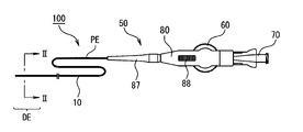
- FIG. 1A is a plan view showing a catheter 100 according to an embodiment of the present invention.
- FIG. 1B is a plan view showing a state where the sheath portion of the catheter 100 is operated in one direction by a rotating operation.
- FIG. 1C is a plan view showing a state in which the sheath portion of the catheter 100 is operated in the other direction by a rotating operation.
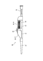
- FIG. 4 is a schematic side view of the operation unit 50 of the catheter 100.
- FIG. 5 is a schematic plan view illustrating the internal structure of the operation unit 50.
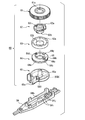
- FIG. 6 is a schematic exploded perspective view of the lower main body 84 and the rotation operation unit 60 in the first embodiment viewed from above.
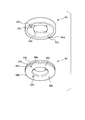
- FIG. 7 is a schematic perspective view of the engaging member 63 and the wire fixing plate 64 in the first embodiment viewed from below.
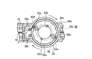
- 8A to 8C are a schematic plan view and a cross-sectional view showing a state in which the engaging member of the catheter shown in FIG. 1A and a wire fixing plate are combined.
- 9A and 9B are views showing a state where the catheter is rotated as shown in FIG. 1A.
- the medical device for example, the catheter 100
- the medical device includes a sheath portion 10, a pair of operation lines 30 (30a, 30b), and a rotation operation portion 60.
- the rotation operation unit 60 includes a hooking member 63, a wire fixing plate 64, and a shaft member 65.
- the rotation operation unit 60 includes a winding part 64c as a winding part, and a through part 63c and a closing part 63d as guard parts.
- the sheath part 10 is long and flexible.
- the pair of operation lines 30 extends into the sheath portion 10, and a tip is disposed at the distal portion DE of the sheath portion 10.
- the rotation operation unit 60 is provided on the proximal end side of the sheath unit 10, and pulls one operation line 30 and sends the other operation line 30 by the rotation operation, and corresponds to one pulled operation line 30.
- the sheath portion 10 is bent in the direction to be moved.
- the proximal end side of the sheath part 10 means the side close to the operation part 50.
- the wire fixing plate 64 (winding portion) has a winding portion 64c (side peripheral surface) as shown in FIGS. 6 and 7, and the operation line 30 is wound around the winding portion 64c.
- the hooking member 63 has a through-hole 63c and a closing part 63d (guard part), which are on the outer side in the radial direction from the winding part 64c and at a position facing the winding part 64c. It is provided so as to be integrated with the fixed platen 64.
- the guard part is arrange
- the relative positions of the winding part (wire fixing plate 64) and the guard part (penetrating part 63c and blocking part 63d) are not changed even if the turning operation is performed.
- the guard portion is outside the region around which the operation line 30 is wound (winding portion 64c) and is located at a position facing the region. For this reason, the guard portion can hook or hold down the operation line 30 wound around the region. Therefore, it is possible to prevent the operation line 30 that has slackened from the winding part due to the turning operation from deviating from the winding part.
- the “winding portion” refers to a member that is rotated by a turning operation for bending the sheath portion 10 with the operation wire 30 wound around the side peripheral surface thereof.
- the wire fixing board 64 is a winding part
- the winding part 64c is the side peripheral surface.
- the “guard portion” refers to a member provided so as to be integrated with the winding portion in order to prevent the operation line 30 from deviating.
- the winding part and the guard part may be originally an integral member, or the winding part and the guard before assembly.
- the part may be an individual member. In the above aspect, after assembling (finished product), the winding part and the guard part may be directly coupled, or the winding part and the guard part may be connected via another member. .
- the “position facing the side circumferential surface” refers to a position seen from the side circumferential surface (winding portion 64c), and is not necessarily limited to a position facing the side circumferential surface. Therefore, as long as the purpose is achieved, the positions where the guard portions (the through portion 63c and the blocking portion 63d) are provided are not limited to the positions included in the wire fixing plate 64 as in the present embodiment, but are outside the wire fixing plate 64. It may be.
- the operation unit 50 includes an operation unit main body 80 attached to the proximal end PE of the sheath unit 10, and a plurality of operation lines 30 a and 30 b, respectively, by rotation operation. And a rotation operation unit 60 for individually applying a traction force.
- the operation unit main body 80 is a housing that is held by a user's hand.
- the proximal end portion PE of the sheath portion 10 is protected by a tubular protector 87 and is introduced into the operation portion main body 80.
- the operation unit main body 80 is formed by sandwiching the rotation operation unit 60 (the dial operation unit 61, the shaft member 65, etc.) from above and below by the upper main body 82 and the lower main body 84.
- the separation surface 81 corresponds to a joint surface between the upper body 82 and the lower body 84.
- the operation unit 50 includes a hub connector 70 in addition to the operation unit main body 80 and the rotation operation unit 60.
- the hub connector 70 is attached to the rear end portion of the operation unit main body 80.
- the hub connector 70 is connected to and communicates with the most proximal end (proximal end) of the sheath portion 10, and a syringe (not shown) is attached from the rear of the hub connector 70 (right side in FIG. 1A). Is done.
- the drug solution or the like By injecting the drug solution or the like into the hub connector 70 by the syringe, the drug solution or the like can be supplied into the body cavity of the subject through the main lumen 20 (see FIGS. 2 and 3) of the sheath portion.
- the dimension of the operation unit 50 that is, the dimension from the front end of the protector 87 to the rear end of the hub connector 70 can be arbitrarily selected, but is preferably about 5 cm to 15 cm.
- operation lines 30 a and 30 b are inserted through the sheath portion 10.
- the operation lines 30 a and 30 b are drawn laterally from the sheath portion 10 inside the operation portion main body 80 and are directly or indirectly connected to the rotation operation portion 60.
- the sheath portion 10 from which the operation lines 30a and 30b are drawn can be connected to the hub connector 70 as described above.
- the rotation operation unit 60 of the present embodiment is rotatable with respect to the operation unit main body 80.
- the rotation amount and rotation angle of the rotation operation unit 60 are arbitrarily selected. In this embodiment, rotation and rotation are not distinguished.
- rotation operation unit 60 When the rotation operation unit 60 is rotated in one direction, the first operation line 30a is tensioned and the second operation line 30b is relaxed.
- the second operation line 30b When the rotation operation unit 60 is rotated in the other direction, the second operation line 30b is tensioned and the first operation line 30a is relaxed.
- the operation lines 30a and 30b are individually fixed at the distal portion DE. For this reason, the pulled operation lines 30 a and 30 b bend the distal portion DE of the catheter 100.
- FIG. 1B when the rotation operation unit 60 is rotated in one direction (clockwise), the first operation line 30a (see FIG. 3) is pulled to the proximal end side and sheathed.
- the distal part DE of the part 10 is bent.
- FIG. 1C when the rotation operation unit 60 is rotated in the other direction (counterclockwise) around the rotation axis, the second operation line 30b is pulled to the proximal end side, and the distal portion DE is reversed. Bend to.
- the distal portion DE of the catheter 100 can be selectively bent in the first or second direction included in the same plane. Can do.
- the bending of the sheath portion 10 includes a manner in which the sheath portion 10 is bent and a manner in which the sheath portion 10 is bent like a bow.
- An uneven engagement portion (a structure having a peak flange portion and a valley portion) is formed on the peripheral surface of the rotation operation portion 60 (dial operation portion 61: see FIG. 6).
- the operation unit body 80 is provided with a lock slider 88 that slides on and off the rotation operation unit 60.
- the lock slider 88 When the lock slider 88 is slid toward the rotation operation unit 60, they are engaged with each other to restrict the rotation of the rotation operation unit 60. Thereby, in the state of FIG. 1B or 1C in which the distal portion DE of the catheter 100 is bent, the rotation of the rotation operation unit 60 is restricted by the operation of the lock slider 88, and the bent state of the catheter 100 can be maintained. it can.
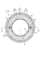
- FIG. 2 is a transverse sectional view of the catheter 100 of FIG. 1A and a sectional view taken along the line II-II.
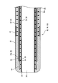
- 3 is a longitudinal sectional view of the distal portion DE of the catheter 100 of FIG. 1A, and is a sectional view taken along line III-III of FIG.
- the catheter 100 of the present embodiment is an intravascular catheter that is used by inserting the sheath portion 10 into a blood vessel.
- the sheath portion 10 is a hollow tubular and long member having a main lumen 20 formed therein.
- the sheath portion 10 is preferably formed to have an outer diameter and a length that can enter any of the eight sub-regions of the liver.
- the outer diameter of the distal portion DE of the sheath portion 10 is preferably less than 1 mm, and the catheter 100 of this embodiment can be used as a microcatheter that can be inserted into a peripheral blood vessel.
- the sheath portion 10 has a main lumen 20 and a plurality of sub-lumen 32 having a smaller diameter than the main lumen 20 and having a plurality of operation lines 30a and 30b inserted therethrough.
- the number of operation lines 30a and 30b and the number of auxiliary lumens can be arbitrarily selected.
- the sheath portion 10 is a resin that defines a wire reinforcing layer 26 formed by winding a reinforcing wire 24 around the main lumen 20 and a sub-lumen 32 that is embedded outside the wire reinforcing layer 26 and has a smaller diameter than the main lumen 20.
- the sheath portion 10 has a laminated structure.
- the sheath portion 10 is configured by laminating an inner layer 22, a first outer layer 34, and a second outer layer 36 in order from the inner diameter side, with the main lumen 20 as the center. It is preferable that a hydrophilic layer (not shown) is formed on the outer surface of the second outer layer 36.
- the inner layer 22, the first outer layer 34, and the second outer layer 36 are made of a flexible resin material, and each has an annular shape and a substantially uniform thickness.
- the first outer layer 34 and the second outer layer 36 may be collectively referred to as an outer layer 38.
- the inner layer 22 is the innermost layer of the sheath portion 10, and the main lumen 20 is defined by the inner wall surface thereof.
- the cross-sectional shape of the main lumen 20 is not particularly limited and can be arbitrarily selected, it is circular in this embodiment.
- the diameter thereof may be uniform over the longitudinal direction of the sheath portion 10 or may be different depending on the position in the longitudinal direction.
- a taper shape in which the diameter of the main lumen 20 continuously increases from the distal end toward the proximal end may be employed.
- the material of the inner layer 22 can be selected arbitrarily, and examples thereof include a fluorine-based thermoplastic polymer material.
- a fluorine-based thermoplastic polymer material include polytetrafluoroethylene (PTFE), polyvinylidene fluoride (PVDF), and perfluoroalkoxy fluororesin (PFA).
- PTFE polytetrafluoroethylene
- PVDF polyvinylidene fluoride
- PFA perfluoroalkoxy fluororesin
- a wire reinforcing layer 26 and a hollow tube 28 are embedded in the first outer layer 34 corresponding to the inner layer of the outer layer 38 in order from the inner diameter side.
- a second reinforcing layer 40 is provided inside the second outer layer 36 that is the outer layer of the outer layer 38. The second reinforcing layer 40 is in contact with the outer surface of the first outer layer 34.
- the wire reinforcing layer 26 and the second reinforcing layer 40 are arranged coaxially with the sheath portion 10.
- the second reinforcing layer 40 is spaced apart from the wire reinforcing layer 26 and the hollow tube 28 so as to surround them.
- the material of the outer layer 38 can be arbitrarily selected, but a thermoplastic polymer material can be preferably used.
- this thermoplastic polymer material include polyimide (PI), polyamideimide (PAI), polyethylene terephthalate (PET), polyethylene (PE), polyamide (PA), polyamide elastomer (PAE), and polyether block amide (PEBA).
- nylon elastomer polyurethane (PU), ethylene-vinyl acetate resin (EVA), polyvinyl chloride (PVC) or polypropylene (PP).
- the outer layer 38 may be mixed with an inorganic filler.
- the inorganic filler include contrast agents such as barium sulfate and bismuth subcarbonate.
- the first outer layer 34 and the second outer layer 36 contain the same or different resin materials. Although the boundary surface between the first outer layer 34 and the second outer layer 36 is clearly shown in FIG. 2, the present invention is not limited to this. When the 1st outer layer 34 and the 2nd outer layer 36 are comprised with the same kind of resin material, the interface of both layers may be united naturally. That is, the outer layer 38 of the present embodiment may be formed of a multilayer in which the first outer layer 34 and the second outer layer 36 can be distinguished from each other, or the first outer layer 34 and the second outer layer 36 are integrated. It may be configured as a single layer.
- the hydrophilic layer formed on the outer surface of the second outer layer 36 constitutes the outermost layer of the catheter 100. Although the new water layer is omitted in FIG. 2, it may be considered that the new water layer is the surface of the catheter 100 shown in FIG. 1A or the like.
- the hydrophilic layer may be formed over the entire length of the sheath portion 10, or may be formed in a partial length region on the tip side including the distal portion DE.
- the hydrophilic layer may be formed of any material, and includes, for example, a maleic anhydride polymer such as polyvinyl alcohol (PVA), a copolymer thereof, and a hydrophilic resin material such as polyvinyl pyrrolidone.
- the wire reinforcement layer 26 is a protective layer that is provided on the inner diameter side of the operation line 30 in the sheath portion 10 and protects the inner layer 22.
- the presence of the wire reinforcing layer 26 on the inner diameter side of the operation line 30 prevents the operation line 30 from breaking the first outer layer 34 and the inner layer 22 and exposing them to the main lumen 20.
- the wire reinforcing layer 26 is formed by winding a reinforcing wire 24.
- the material of the reinforcing wire 24 includes a metal material such as tungsten (W), stainless steel (SUS), nickel titanium alloy, steel, titanium, copper, titanium alloy or copper alloy, as well as the inner layer 22 and the first outer layer 34.
- the reinforcing wire 24 is a fine stainless steel wire.
- the wire reinforcing layer 26 is formed by braiding the reinforcing wire 24 in a coiled or mesh shape.
- the number of the reinforcing wires 24, the coil pitch, and the number of meshes can be arbitrarily selected and are not particularly limited.
- the wire reinforcing layer 26 of the present embodiment is a blade layer obtained by braiding a plurality of reinforcing wires 24 in a mesh shape.
- the hollow tube 28 is a hollow tubular member that defines the secondary lumen 32.
- the hollow tube 28 is embedded in the first outer layer 34.
- the hollow tube 28 can be made of, for example, a thermoplastic polymer material.
- the thermoplastic polymer material include low friction resin materials such as polytetrafluoroethylene (PTFE), polyetheretherketone (PEEK), or tetrafluoroethylene / hexafluoropropylene copolymer (FEP).
- PTFE polytetrafluoroethylene
- PEEK polyetheretherketone
- FEP tetrafluoroethylene / hexafluoropropylene copolymer
- Be The hollow tube 28 is made of a material having a higher bending rigidity and tensile elastic modulus than the outer layer 38.
- two hollow tubes 28 are arranged around the wire reinforcing layer 26 so as to face each other by 180 degrees, and the operation wires 30 (30a, 30b) are disposed in the two hollow tubes 28. Are respectively inserted.
- the two hollow tubes 28 are parallel to the axial direction of the sheath portion 10.
- the two hollow tubes 28 are arranged on the same circumference so as to surround the main lumen 20.
- three or four hollow tubes 28 may be arranged around the main lumen 20 at equal intervals.
- the operation lines 30 may be arranged in all the hollow tubes 28, or the operation lines 30 may be arranged in some of the hollow tubes 28.
- the operation line 30 is slidably inserted into the hollow tube 28.
- the distal end portion of the operation line 30 is fixed to the distal portion DE of the sheath portion 10.
- a tensile force is applied to a position that is eccentric with respect to the axial center of the sheath portion 10, so that the sheath portion 10 bends.
- the operation line 30 of this embodiment is extremely thin and highly flexible, even if the operation line 30 is pushed toward the distal end side, substantially no pushing force is applied to the distal portion DE of the sheath part 10. Further, the operation line 30 is easily slackened by a turning operation.
- the operation wire 30 may be formed of a single wire, but may be a stranded wire formed by twisting a plurality of thin wires.
- the number of fine wires constituting one strand of the operation wire 30 is not particularly limited, but is preferably 3 or more.
- a preferable example of the number of thin wires is seven or three.
- low carbon steel (piano wire), stainless steel (SUS), steel wire coated with corrosion resistance, titanium or a titanium alloy, or metal wire such as tungsten can be used.
- the operation line 30 includes polyvinylidene fluoride (PVDF), high density polyethylene (HDPE), poly (paraphenylenebenzobisoxazole) (PBO), polyetheretherketone (PEEK), polyphenylene sulfide (PPS), Polymer fibers such as polybutylene terephthalate (PBT), polyimide (PI), polytetrafluoroethylene (PTFE), or boron fiber can be used.
- PVDF polyvinylidene fluoride
- HDPE high density polyethylene
- PBO poly (paraphenylenebenzobisoxazole)
- PEEK polyetheretherketone
- PPS polyphenylene sulfide
- Polymer fibers such as polybutylene terephthalate (PBT), polyimide (PI), polytetrafluoroethylene (PTFE), or boron fiber can be used.
- two operation lines 30 are respectively inserted into the hollow tubes 28 and are individually fixed to the distal portion DE of the sheath portion 10.
- two operating lines 30 may be formed by two wires individually, or one wire is folded at the distal portion DE of the sheath portion 10 and both ends rotate.
- the operation unit 60 may be individually towable. That is, in the present embodiment, the number of operation lines 30 being plural or two means that there are a plurality of or two paths for applying a traction force that bends the distal portion DE of the sheath portion 10. If the two operation lines 30 are configured by folding one wire at the distal portion DE of the sheath portion 10, the tip of the operation line 30 is the wire folded portion at the distal portion DE. Say.
- the second reinforcing layer 40 is a protective layer that is provided on the outer peripheral side of the operation line 30 in the sheath portion 10 and protects the second outer layer 36.
- the presence of the second reinforcing layer 40 on the outer peripheral side of the operation line 30 prevents the operation line 30 from being exposed to the outside of the sheath portion 10 by breaking the second outer layer 36 and the hydrophilic layer (not shown).
- the second reinforcing layer 40 is configured by winding the second reinforcing wire 42 in a coiled or mesh shape.
- the above-described materials exemplified as the reinforcing wire 24 of the wire reinforcing layer 26 can be used.
- the second reinforcing wire 42 and the reinforcing wire 24 may be made of the same material or different materials.
- a blade layer in which fine wires including the same type of material (stainless steel) as the reinforcing wire 24 are braided in a mesh shape is illustrated.
- the wire diameter and the number of strips of the second reinforcing wire 42 and the reinforcing wire 24 may be the same or different.
- a distal portion DE of the sheath portion 10 is provided with a first marker 14 and a second marker 16 located on the proximal side of the first marker 14.
- the first marker 14 and the second marker 16 are ring-shaped members containing a material that does not transmit radiation such as X-rays, such as platinum.
- the distal portion of the distal portion DE with respect to the second marker 16 is bent.
- the distal end portion of the operation line 30 is fixed to the first marker 14.
- the mode of fixing the operation line 30 to the first marker 14 is not particularly limited, and examples thereof include solder bonding, heat fusion, adhesion with an adhesive, and mechanical engagement between the operation line 30 and the first marker 14. .
- the proximal ends of the wire reinforcing layer 26 and the second reinforcing layer 40 are located up to the proximal end of the sheath portion 10, that is, inside the operation portion 50.
- the distal end of the inner layer 22 may extend to the distal end of the sheath portion 10 or may be terminated slightly proximally, i.e. slightly inward, than the distal end of the sheath portion 10. Also good.
- the proximal end of the inner layer 22 is located up to the proximal end of the sheath portion 10, that is, inside the operation portion 50.
- the example of the typical dimension of the sheath part 10 is demonstrated.
- the diameter of the main lumen 20 is 400 ⁇ m to 600 ⁇ m (including upper and lower limits; the same applies hereinafter), the inner layer 22 has a thickness of 5 ⁇ m to 30 ⁇ m, and the outer layer 38 has a thickness of 10 ⁇ m to 200 ⁇ m.
- the wall thickness of the hollow tube 28 is thinner than the inner layer 22 and is 1 ⁇ m to 10 ⁇ m.
- the inner diameter of the wire reinforcing layer 26 is 410 ⁇ m to 660 ⁇ m, the outer diameter of the wire reinforcing layer 26 is 450 ⁇ m to 740 ⁇ m, the inner diameter of the second reinforcing layer 40 is 560 ⁇ m to 920 ⁇ m, and the outer diameter of the second reinforcing layer 40 is 600 ⁇ m to 940 ⁇ m.
- the inner diameter of the first marker 14 is 450 ⁇ m to 740 ⁇ m, the outer diameter of the first marker 14 is 490 ⁇ m to 820 ⁇ m, the inner diameter of the second marker 16 is 600 ⁇ m to 940 ⁇ m, and the outer diameter of the second marker 16 is 640 ⁇ m to 960 ⁇ m.
- the radius (distance) from the axial center of the catheter 100 to the center of the hollow tube 28 is 300 ⁇ m to 450 ⁇ m, the inner diameter (diameter) of the hollow tube 28 is 40 ⁇ m to 100 ⁇ m, and the thickness of the operation line 30 is 25 ⁇ m to 60 ⁇ m.
- the diameter of the sheath portion 10 is 700 ⁇ m to 980 ⁇ m, that is, the outer diameter is less than 1 mm, and the sheath portion 10 constitutes a microcatheter that can be inserted into a peripheral blood vessel.
- the linear expansion coefficient of the sheath portion 10 is larger than the linear expansion coefficient of the operation line 30.
- the linear expansion coefficient of the sheath portion 10 is 100 ppm / K or more and 300 ppm / K or less
- the cell expansion coefficient of the operation line 30 is 10 ppm / K or more and 30 ppm / K or less.
- the swelling coefficient of the sheath portion 10 is larger than the swelling coefficient of the operation line 30.
- the linear expansion coefficient or the swelling coefficient of the sheath part 10 is a linear expansion coefficient or a swelling coefficient when viewed as a whole of the laminated structure of the sheath part 10.
- the linear expansion coefficient or the swelling coefficient The individual linear expansion coefficient or swelling coefficient of each component can be estimated by multiplying the Young's modulus and the area ratio in the cross-sectional area.
- FIG. 5 is a schematic plan view illustrating the internal structure of the operation unit 50.
- FIG. 6 is a schematic exploded perspective view of the lower main body 84 and the rotation operation unit 60 in this embodiment as viewed from above.
- FIG. 7 is a schematic perspective view of the engaging member 63 and the wire fixing plate 64 in this embodiment as viewed from below.
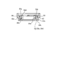
- FIG. 8A is a schematic plan view of the state in which the engaging member 63 and the wire fixing plate 64 in the present embodiment are combined as viewed from above.
- 8B is a cross-sectional view taken along the line BB of FIG. 8A.
- FIG. 9A is a schematic diagram showing a state in which the operation line 30 is slackened in the wire fixing plate 64, and a rotation operation is performed clockwise.
- FIG. 9B is a schematic diagram illustrating a time when a rotation operation is performed counterclockwise.
- the base end portion PE of the sheath portion 10 passes through the lower portion of the rotation operation portion 60 and is pulled out rearward from the rear end portion 84b of the operation portion main body 80 (lower side main body 84). Yes.
- a side hole 12 extending from the outer peripheral surface of the sheath portion 10 to the hollow tube 28 is formed in the proximal end portion PE of the sheath portion 10 at a position corresponding to the inside of the operation portion main body 80.
- the side hole 12 penetrates the peripheral surface of the hollow tube 28.
- the operation lines 30 a and 30 b are drawn out from the inside of the hollow tube 28 to the outside side through the side holes 12.
- the operation wires 30 a and 30 b drawn from the hollow tube 28 through the side holes 12 are fixed at the base ends to the wire fixing plate 64 of the rotation operation unit 60, and are wound by the rotation of the wire fixing plate 64. Towed by. More specifically, the wire fixing plate 64 has a plurality of engaging portions 66, and the base ends of the operation lines 30a and 30b are entangled with the predetermined engaging portions 66 and fixed by an adhesive. Yes. A method of entanglement of the base end of the operation line with the engaging portion 66 can be arbitrarily selected.
- the operation lines 30a and 30b are wound around the wire fixing plate 64 in directions opposite to each other in a direction opposite to the upper limit angle of the rotation operation, and even if the operation line 30 is rotated to the upper limit angle, the operation line 30 is not sufficiently delivered It is supposed not to.
- the winding angle may mean an angle obtained by confirming from above the state in which the operation line is wound around the winding portion 64c.
- the upper limit angle of the turning operation is about 135 degrees.
- the wrapping angle of the operation lines 30a and 30b in the initial state is more than 360 degrees and less than 720 degrees. As described above, by setting the winding angle sufficiently to exceed the upper limit angle of the rotation operation, the slack of the operation line 30 is dispersed, and the distance at which the operation line 30 is separated from the wire fixing plate 64 is reduced.
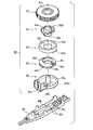
- the rotation operation unit 60 of the present embodiment includes a dial operation unit 61, a limiter member 62, a hooking member 63, a wire fixing plate 64, and a shaft member 65.
- the dial operation unit 61 is disposed on the outer peripheral side of the rotation operation unit 60, and is a turntable that is operated by the operator directly touching with fingers.
- the limiter member 62 is attached to the dial operation unit 61 so as not to rotate.
- the limiter member 62 has a spring engaging portion 62a and a shaft portion 62b.
- the spring engaging portion 62 a is an elastically deformable member that is deformable so as to protrude and retract in the radial direction of the limiter member 62.
- the rotation shaft 65a of the shaft member 65 is inserted through the shaft portion 62b.
- a non-circular locking convex part 62c is formed on the upper part of the shaft part 62b.
- the locking projection 62 c is fitted to the opening 61 c of the dial operation unit 61 so as not to rotate. As a result, the limiter member 62 and the dial operation unit 61 rotate together around the rotation shaft 65a.
- the engaging member 63 is an annular member that is inserted through the shaft portion 62b of the limiter member 62 and is detachably engaged with the spring engaging portion 62a.
- the hooking member 63 has a bottomed annular shape, and a corrugated uneven portion 63a is formed on the inner peripheral surface of the circular peripheral wall.
- the spring engaging portions 62a of the limiter member 62 are engaged at a plurality of locations in the circumferential direction of the uneven portion 63a. When the limiter member 62 and the engaging member 63 are relatively twisted with a torque of a predetermined value or more, the engagement between the spring engaging portion 62a and the concavo-convex portion 63a is released.
- the engaging member 63 has a plurality of recessed portions 63b.
- the wire fixing plate 64 is a bobbin around which the operation lines 30a and 30b are wound.
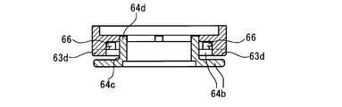
- the wire fixing plate 64 includes a pair of large-diameter flange portions 64b and a small-diameter winding portion 64c formed therebetween.
- a plurality of engaging portions 66 are formed in the upper flange portion 64b. In FIG. 6, one engaging portion 66 is formed on each side of the two slits 64a.
- a plurality of protrusions 64 d are formed on the upper surface of the wire fixing plate 64.
- the hooking member 63 is fixed to the wire fixing plate 64 so as not to rotate, and both are rotatably supported by the shaft member 65. ing.
- the limiter member 62 and the engaging member 63 act according to the reaction force received from the operation line 30 by the turning operation, and constitute a traction amount limiting unit that limits the traction of the operation lines 30a and 30b to a predetermined amount or less. is doing.
- the configuration example of the traction amount limiting unit that limits the torque (traction force) to a predetermined value or less is shown, but the distance (traction length) that pulled the operation line 30 may be limited to a predetermined value or less. .
- the wire fixing plate 64 (winding portion) includes a winding portion 64c (side peripheral surface), upper and lower flange portions 64b formed on the winding portion 64c, and a lower flange. It includes an opening 64e provided in the portion 64b and a protrusion 64f. And the penetration part 63c (guard part) of the engaging member 63 is a projection part which penetrates into the opening part 64e. Further, the wire fixing plate 64 (winding portion) includes a slit 64a (opening portion) in the upper flange portion 64b, and the through portion 63c and the closing portion 63d (guard portion) of the engaging member 63 are protrusions that penetrate into the slit 64a. Part.
- the wire fixing plate 64 (winding portion) is formed with a pair of flange portions 64b so as to sandwich the winding portion 64c (side peripheral surface), and the pair of flange portions 64b has an opening 64e.
- the slit 64a is provided so that it may mutually oppose.
- the penetrating part 63c of the engaging member 63 is provided as a guard part from the slit 64a (one opening part) to the opening part 64e (other opening part) in the rotation axis direction of the winding part 64c (side peripheral surface). ing.
- the dimension (length) through which the penetrating portion 63c protrudes from the slit 64a is larger than the thickness of the winding portion 64c.
- the tip of the penetration part 63c enters the opening part 64e.
- the wire fixing plate 64 is in an area surrounded by the winding portion 64c, the flange portion 64b, and the guard portions (the through portion 63c and the closing portion 63d) of the engaging member 63 (see FIG. 8B), the operation line 30 can be pressed down, and deviation of the operation line 30 can be prevented.
- the operation line 30 separated from the winding portion 64c by the turning operation is enlarged in a substantially circular shape.
- the flange portion 64b needs to allow the slack of the operation line 30 to some extent in the inner region of the flange portion for smooth rotation operation.
- the flange portion 64b needs to suppress the slackness of the operation line 30 into its internal region. For this reason, a circular shape or a shape approximating a circular shape is suitable for the shape of the flange portion 64b.
- the guard part is provided inside the inclusion circle centering on the rotating shaft of the wire fixing board 64 (winding part), including the flange part 64b, and contacting the outer peripheral surface of the flange part 64b.
- the inclusion circle virtually represents the limit of the slackness of the operation line 30 allowed by the flange portion 64b.
- the flange part 64b in this embodiment is circular shape, the outer peripheral surface of the flange part 64b is equal to the said inclusion circle.
- the guard portion is provided inside the inclusion circle” means that at least a part of the guard portion may be arranged inside the inclusion circle. However, it is more preferable that the entire guard portion is disposed inside the inclusion circle. According to this embodiment, it is preferable that the penetration part 63c and the closing part 63d of the engaging member 63 which is a guard part are respectively arranged inside the inclusion circle.
- the rotation operation unit 60 has the engaging member 63 (fitting portion) that is fitted in the rotation axis direction of the wire fixing plate 64 with respect to the wire fixing plate 64 (winding portion). is doing. Further, as shown in the figure, the penetrating part 63c and the blocking part 63d (guard part) are connected to the operation line 30 wound around the winding part 64c by fitting the engaging member 63 to the wire fixing plate 64. It arrange
- “fitted” refers to a state in which one of the hooking member 63 and the wire fixing plate 64 is inserted inside or attached to the other.
- the wire fixing plate 64 and the guard part are constituted by separate members.
- a guard part can be attached after winding the operation wire 30 around the wire fixing board 64 (winding part 64c).
- the winding operation of the operation line 30 can be easily performed, and is particularly suitable for the catheter 100 in which the winding angle of the operation line 30 in the initial state exceeds 360 degrees as in this embodiment. is there.
- the guard portion can be attached to a desired position and the fitting state can be maintained by a simple operation of fitting the engaging member 63 in the axial direction of the wire fixing plate 64.
- the penetration part 63c in this embodiment is formed when one protrusion part penetrates from the slit 64a to the opening part 64e, it is not necessarily restricted to this aspect.
- the protrusion protruding from the slit 64a and the protrusion protruding from the opening 64e are arranged so as to overlap each other when viewed from the center of rotation, so that these protrusions are connected to the through-hole 63c of the present embodiment. It may be an aspect that functions equally.
- the winding part 64c, the flange part 64b, and the penetration part 63c in the present embodiment are configured to surround all directions around the operation line 30 when viewed as a cross section, for example. However, it does not necessarily surround all directions, and there may be a gap with respect to some directions. Therefore, the dimension by which the penetration part 63c protrudes from the slit 64a may be smaller than the thickness of the winding part 64c.
- the position of the through portion 63c can be arbitrarily set as long as the purpose can be achieved.
- the penetrating portion 63 c passes through a contact / separation point where the operation line 30 contacts / separates from the winding portion 64 c in the initial state, and from the contact / separation point to the sheath portion 10 side.
- a straight line is drawn on the operation line 30 that is drawn out toward the hole 12, it is preferably provided outside the straight line in the width direction of the operation unit 50.
- the penetrating portion 63c faces the operation line 30 on the base end side from the contact / separation point (the operation line 30 on the engaging portion 66 side which is the fixed end in the rotation operation unit 60).
- the penetrating portion 63c moves so as to follow the operation line 30 that has been sent out by the turning operation and once slackened, and the penetrating portion 63c can hook the operation line 30. . Further, in the turning operation after the operation line 30 is hooked, the route of the operation line 30 varies due to the movement of the penetrating portion 63c, and the slackness generated in the operation line 30 is suppressed.
- the position of the penetration part 63c may be changed according to the winding angle of the selected operation line.
- a slit 64a (notch) is formed in the wire fixing plate 64 (winding portion) as an opening inward from the outer peripheral side of the flange portion 64b.
- the operation line 30 drawn from the slit 64 a is fixed to the engaging portion 66 of the wire fixing plate 64.
- the closing part 63d (guard part) closes the outer peripheral side of the winding part 64c in the slit 64a.
- a slit 64 a provided for drawing the operation line 30 to the engaging portion 66 is one of the places where the operation line 30 is likely to deviate from the wire fixing plate 64. Accordingly, the slit 64a is preferable for the position where the blocking portion 63d is provided.
- the penetrating portion 63c of the engaging member 63 of the present embodiment is provided from the slit 64a (notch) of the pair of flange portions 64b to the opening 64e (other opening), and the closing portion 63d of the engaging member 63 is In the slit 64a, the outer peripheral side is closed from the position of the through-hole 63c.
- the gap between the slit 64a and the closing part 63d is smaller than the diameter of the operation line 30. This can more reliably prevent the operation line 30 from deviating from the slit 64a.
- the penetrating part 63c and the blocking part 63d are integrally formed.
- the present invention is not limited to this mode, and the penetrating part 63c and the blocking part 63d It may be an embodiment in which a gap is provided between them.
- a plurality of slits 64a are formed in the flange portion 64b.
- the number of slits can be set arbitrarily.
- a pair of operation lines 30 a and 30 b are drawn out from different slits 64 a and fixed to the wire fixing plate 64.
- a penetrating portion 63c and a blocking portion 63d are formed for each of the plurality of slits 64a from which the operation lines 30a and 30b are drawn. That is, the wire fixing plate 64 is provided with a pull-in slit 64a and an engaging portion 66 for each operation line 30a, 30b, and prevents the operation lines 30a, 30b from being tangled in the vicinity of the engaging portion 66. Yes. And by providing the penetration part 63c and the obstruction
- the shaft member 65 is a holding member having a circular recess that accommodates the wire fixing plate 64, and includes a rotating shaft 65 a that protrudes upward and guide ribs 65 b and 65 c that protrude downward. It has.
- occlusion part 63d (guard part) of the engaging member 63 in the internal space contained by the shaft member 65 which accommodates the wire fixing board 64 like this embodiment. This is because the shaft member 65 is a member that accommodates the wire fixing plate 64 that functions as the winding portion of the present invention, and the present invention aims to prevent the operation line 30 from deviating from the winding portion. Because.
- a dial operation unit 61, a limiter member 62, a hooking member 63, and a wire fixing plate 64 are rotatably mounted on the rotary shaft 65a.
- the rotation operation part 60 is comprised integrally.
- the guide ribs 65b and 65c are two pairs of parallel plate-like protrusions.
- the pair of guide ribs 65c are formed with claw portions 68 that protrude outward.
- the shaft member 65 has a guide groove 65d that is an arcuate groove on the upper side (see FIG. 6), and the guide groove 65d is a protrusion 64f (see FIG. 7) provided below the wire fixing plate 64. ). That is, the guide groove 65d and the protrusion 64f are engaged when the rotation operation reaches a predetermined rotation angle, and constitute an angle limiting mechanism that limits the rotation operation. In the present embodiment, by reaching a rotation operation of about 135 degrees, the protrusion 64f comes into contact with the end of the guide groove 65d, and the rotation operation is restricted.
- the operation portion 30c comes into contact with the operation line 30 on the side where the penetrating portion 63c is pulled, and extra tension is applied.
- the line 30 is easily broken.
- the angle limiting mechanism in the present embodiment can prevent the operation line 30 from being broken.
- the protrusion 64f and the guide groove 65d of the present embodiment are examples of an angle limiting mechanism, and the angle limiting mechanism may be realized by other modes.
- the lower main body 84 includes an inner guide 84j that contacts the guide rib 65b and an intermittent rib 84i that contacts the guide rib 65c.
- the inner guide 84j and the intermittent rib 84i are a pair of plate-like convex portions that extend in the front-rear direction of the lower main body 84, respectively.
- the pair of intermittent ribs 84i is a set of a plurality of rib pieces that are divided by the gaps 84h and are discretely formed.
- the claw portion 68 engages with the gap 84h
- the guide rib 65c is disposed along the inside of the pair of intermittent ribs 84i
- the guide rib 65b includes the inner guide 84j and the intermittent rib 84i. Between them.
- the rotary operation unit 60 formed by integrally combining the dial operation unit 61, the limiter member 62, the hooking member 63, the wire fixing plate 64, and the shaft member 65 is attached to the lower body 84 and fixed. Has been.
- FIGS. 9A and 9B are diagrams showing a state in which the operation line 30 is loose in the wire fixing plate 64.
- FIG. 9A is a diagram illustrating a state in which a clockwise rotation operation is performed and an upper limit angle (about 135 degrees in the present embodiment) is reached.
- FIG. 9B is a diagram illustrating a state in which the rotation operation is performed counterclockwise and the upper limit angle is reached.
- the pulled operation line 30a is in a tension state
- the sent operation line 30b is in a relaxed state.
- the penetrating portion 63c comes into contact with the operation line 30b (other operation line) sent out by the rotation operation when the rotation operation reaches a predetermined angle, and further, the operation line 30b is moved by the rotation operation exceeding the predetermined angle. Pull in the direction of rotation of the turning operation.
- the wire fixing plate 64 is rotated by the turning operation, but the shaft member 65 is not rotated. Therefore, it is difficult to closely contact each other, and it is necessary to provide a gap at least.
- the operation line 30b slackened from the gap can deviate.
- the operation line 30b in the present embodiment is once slackened by the rotation operation, it is caught by the moving through part 63c penetrating through the slit 64a from which the operation line 30a is drawn, and the operation line 30b is operated by the through part 63c. It is pulled to the 30a side.
- the routing route of the operation line 30b varies and the slack generated in the operation line 30b is absorbed, so that the operation line 30b does not deviate from the gap.
- the through portion 63c is provided integrally with the wire fixing platen 64, the rotation angle of the wire fixing platen 64 (the feed amount of the operation line 30b) increases, and the moving distance of the through portion 63c increases. The degree of fluctuation of the routing route of the line 30b also increases. That is, even if the rotation angle of the rotation operation increases, the through portion 63c can sufficiently suppress the slack that occurs in the operation line 30b.
- the catheter 100 is returned to the initial state by the operation line 30 curved by contacting the penetration portion 63c being caught at the corner of the slit 64a. It is possible to prevent the trouble that disappears.
- the catheter 100 includes the limiter member 62, the engaging member 63, and the (traction amount limiting portion). No tension is applied. More specifically, when the rotation operation is clockwise, the reaction force received by the engaging member 63 from the operation line 30a by the rotation operation is applied counterclockwise (in the opposite direction to the rotation operation).
- the turning operation is clockwise, and the reaction force ( The reaction force is applied clockwise (in the same direction as the rotation operation) in the engaging portion 66 that fixes the operation line 30b, and counterclockwise (reverse to the rotation operation) in the through portion 63c that hooks the operation line 30b.
- the reaction force in the engaging portion 66 is a clockwise vector in the tangential direction on the side peripheral surface of the winding portion 64c.
- the reaction force in the penetrating portion 63c is ( ⁇ ) a vector from the contact point between the penetrating portion 63c and the operation line 30b to the side hole 12 of the sheath portion and ( ⁇ ) the penetrating portion 63c and the operation line 30b.
- a vector from the winding point 64c to the position (contact / separation point) where the operation line 30b contacts / separates from the winding portion 64c and a vector in two directions are combined to act on the engaging member 63 as a counterclockwise force. .
- the angle formed by the vector ( ⁇ ) and the vector ( ⁇ ) becomes an acute angle, and the magnitude of the combined vector (composite force) gradually increases.
- the combined force (counterclockwise reaction force) becomes larger than the reaction force (clockwise reaction force) in the engaging portion 66, and the reaction force received by the engaging member 63 from the operation line 30b is increased. When all are combined, it becomes a counterclockwise vector.
- the limiter member 62 and the engaging member 63 act according to the reaction force received from the operation line 30 by the turning operation, and constitute a traction amount limiting unit that limits the traction of the operation line 30 to a predetermined amount or less. is doing. Further, as is clear from the description of the previous stage, the reaction force received by the engaging member 63 (rotation operation unit) from the operation line 30a (one operation line) by the rotation operation and the rotation direction (clockwise) by the rotation operation. The reaction force received by the engaging member 63 from the operation line 30b (other operation line) that is pulled in the tension state is applied in the same direction (counterclockwise).
- the limiter member 62 and the engaging member 63 are disengaged when the combined force of the tension of the operation line 30a and the tension of the operation line 30b exceeds a predetermined value.
- the limiter member 62 and the engaging member 63 can prevent the addition of a predetermined tension or more with respect to both the operation line 30a and the operation line 30b.
- the limiter member 62 and the engaging member 63 are connected to the operation line for the same reason when the rotation operation is counterclockwise. It prevents that the tension
- FIG. 10 is a schematic exploded perspective view of the lower main body 84 and the rotation operation unit 60 in the second embodiment as viewed from above.
- FIG. 11 is a schematic perspective view of the engaging member 63 and the wire fixing plate 64 in the second embodiment viewed from below.
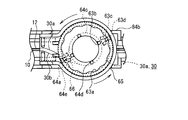
- FIG. 12A is a schematic plan view of a state in which the engaging member 63 and the wire fixing plate 64 in the second embodiment are combined as viewed from above.
- 12B is a cross-sectional view taken along the line BB of FIG. 12A.
- 12C is a cross-sectional view taken along the line CC of FIG. 12A.
- the engaging member 63, the wire fixing plate 64, and the shaft member 65 in the first embodiment are different from the engaging member 63, the wire fixing plate 64, and the shaft member 65 in the second embodiment, respectively.
- the same names are given to components that function equally.
- the members excluding the engaging member 63, the wire fixing plate 64, and the shaft member 65 are common to the first embodiment and the second embodiment, and are omitted in the following description.
- slits 64a are formed inwardly from the outer peripheral side of the flange portion 64b as opening portions, and the operation lines 30a and 30b drawn out from the slit 64a. Is fixed. Then, on the opposite side of the direction in which the operation line 30 is drawn from the separation point toward the sheath portion 10 with reference to the separation point where the operation line 30 is separated from the winding portion 64c (side peripheral surface) in the initial state, Different from the slit 64a, an opening 64e and an opening 64g facing each other are formed in the flange portion 64b. A through-hole 63c penetrates the opening 64e and the opening 64g.
- the initial state means a state when the catheter 100 is shipped or used.
- the penetrating holes are located at positions opposite to the drawing direction of the operation line 30a and opposite to the drawing direction of the operation line 30b.
- a portion 63c is formed. More specifically, in the initial state, the penetrating portion 63c is formed on the central axis of the sheath portion 10 and closer to the proximal end side than the center of the rotation operation, that is, on the rear end side. Further, the separation point of the operation line 30 in the initial state in this embodiment and the direction in which the operation line 30 is drawn from the separation point toward the sheath portion 10 are the same as those in the first embodiment illustrated in FIG. And
- the rotation angle of the rotation operation required until the penetrating portion 63c comes into contact with the operation line 30 on the side sent by the rotation operation is about 90 degrees compared to the first embodiment. growing. Further, the rotation angle of the rotation operation required until the penetrating portion 63c comes into contact with the operation line 30 on the side pulled by the rotation operation is about 90 degrees larger than that in the first embodiment. Thereby, the rotation angle until the engagement between the spring engaging portion 62a and the concavo-convex portion 63a is released is larger than that in the first embodiment. In other words, the catheter 100 can be bent at a large rotation angle even if it does not have a function of limiting the tension applied to the operation line 30 formed by the limiter member 62 and the engaging member 63.
- the guide groove 65d and the protrusion 64f in the first embodiment do not exist. That is, the catheter 100 of this embodiment is different from the first embodiment in that it does not have an angle limiting mechanism. This does not deny that the catheter 100 in the present embodiment is provided with an angle limiting mechanism, and may be provided with some angle limiting mechanism.
- the closing part 63d closes the slit 64a (notch), and the gap between the slit 64a and the closing part 63d is preferably smaller than the diameter of the operation line 30. That is, in the catheter 100 of the first embodiment, the penetration part 63c and the blocking part 63d are integrally formed, whereas in the catheter 100 of the present embodiment, the penetration part 63c and the blocking part 63d are at different positions. It differs in that it is formed to be arranged.
- the through portion 63c in the first embodiment penetrates from the slit 64a to the opening 64e, whereas the through portion 63c in the present embodiment extends downward from the opening 64g provided in the upper flange portion 64b. It differs in that it penetrates the opening 64e provided in the flange 64b. Thereby, it is possible to prevent the operation line 30 from being caught at the corner of the slit 64a or deviating from the slit 64a.
- the dimension (length) of the closed portion 63d penetrating the flange portion 64b in this embodiment is equal to or less than the thickness of the flange portion 64b. This is because when the dimension exceeds the thickness of the flange portion 64b, the operation line 30 is caught by the closing portion 63d by the turning operation, and the closing portion 63d may unexpectedly apply tension to the operation line 30. Because there is.
- FIG. 13 is a schematic exploded perspective view of the lower main body 84 and the rotation operation unit 60 in the third embodiment as viewed from above.
- FIG. 14 is a schematic perspective view of the engaging member 63 and the wire fixing plate 64 in the third embodiment as viewed from below.
- FIG. 15A is a schematic plan view of a state in which the engaging member 63 and the wire fixing plate 64 in the third embodiment are combined as seen from above.
- FIG. 15B is a cross-sectional view taken along the line BB of FIG. 15A.
- FIG. 15C is a cross-sectional view taken along the line CC of FIG. 15A.
- the engaging member 63 and the wire fixing plate 64 in the second embodiment are different from the engaging member 63 and the wire fixing plate 64 in the third embodiment, but they function equally for convenience of explanation. Components are given the same designation. Further, members other than the engaging member 63 and the wire fixing plate 64 are common to the second embodiment and the third embodiment, and are omitted in the following description.
- FIG. 15A the operation lines 30 (30a, 30b) are omitted, but the operation lines 30 are schematically illustrated in FIGS. 15B and 15C.
- the diameter dimension of the operation line 30 illustrated in FIGS. 15B and 15C is enlarged for easy visual recognition, and the dimensional ratio with other parts is not accurate.
- the guard part (penetrating part 63c or blocking part 63d) of the other embodiment described above is a protruding part protruding in a pin shape.
- the guard part 63e of the present embodiment is different in that the guard part 63e extends in one direction and is curved.
- the flange portion 64b of the present embodiment is distorted on the side facing the guard portion 63e and the opposite side, that is, not the same. It differs from the flange part 64b of other embodiment which did.
- the operation line 30 is drawn from the separation point toward the sheath portion 10 with reference to the separation point where the operation line 30 is separated from the winding portion 64c (side circumferential surface).
- a guard portion 63e extends in the opposite direction. As described above, since the guard portion 63e is provided on the side where the slack of the operation line 30 is likely to occur when the rotation operation is started, the effect of preventing the slack of the operation line 30 is sufficiently exhibited from the start of the operation. Is done.
- the operation line 30 in the initial state, is wound around the winding portion 64c (side circumferential surface) at a winding angle exceeding 360 degrees and less than 720 degrees.
- the extending direction of the guard part 63e can be expressed as follows. That is, it can be said that the guard part 63e extends toward the side where the winding by the same operation line 30 is more overlapped, that is, the side where there are many windings.
- the operation lines 30 (30a, 30b) of the present embodiment are all wound on the proximal side, that is, on the rear end side, and independently on the distal side. It is wound. And while the guard part 63e is extended in the proximal side, the guard part 63e is missing in the distal side.
- a pair of engaging portions 66 (fixing portions) in which the proximal ends of the pair of operation lines 30 are individually fixed to the wire fixing plate 64 (winding portion). ) Is formed.
- the extending direction of the guard portion 63e can be rephrased as follows.
- the guard part 63 e is circulated from one engaging part 66 to the other engaging part 66.
- a pair of slits 64a are formed inward from the outer peripheral side of the flange portion 64b in the vicinity of the engaging portion 66, and the operation line 30 is drawn out.
- the flange part 64b in this embodiment is lacking by the area
- the flange portion 64b is covered with the guard portion 63e in a state where the engaging member 63 is fitted to the wire fixing plate 64.
- the hooking member 63 formed in a cylindrical shape with a part cut off covers a part of the wire fixing plate 64.
- the guard portion 63e is It is desirable to be provided inside the inclusion circle.
- the guard part 63e is provided inside the inclusion circle as long as at least the inner peripheral surface of the guard part 63e is disposed inside the inclusion circle.
- the outer peripheral surface of the guard part 63e may be disposed inside the inclusion circle.
- the distance from the inner peripheral surface of the guard part 63e to the winding part 64c (side peripheral surface) is smaller in the vicinity of the engaging part 66 (fixed part) than other parts.
- the wire fixing plate 64 includes a pair of flange portions 64b formed so as to sandwich the winding portion 64c and an upper flange portion 64b (one And a slit 64a (notch) formed inward from the outer peripheral side at the flange portion).
- an engaging portion 66 is formed on one surface opposite to the surface facing the lower (other flange portion).
- the operation line 30 (30a, 30b) wound around the winding portion 64c is drawn out from the slit 64a and entangled with the engaging portion 66. Furthermore, the guard part 63e faces the operation line 30 wound around the winding part 64c and also faces the operation line 30 entangled with the engaging part 66.
- the proximal end side of the operation line 30 is entangled with the engaging portion 66, the looseness of the operation line 30 is likely to be complicated compared to other portions.
- the slit 64a is formed in the vicinity of the engaging part 66, and the malfunction that the operation line 30 is caught at the corner of the slit 64a may occur.
- the guard part 63e in this embodiment is formed so that the inner peripheral surface thereof is closer to the winding part 64c than the other part in the vicinity of the engaging part 66, and the operation line 30 in the vicinity of the engaging part 66 is formed. It is possible to suppress loosening mainly. Further, since the guard part 63e is provided so as to face the operation line 30 entangled with the engaging part 66 (fixed part), the operation line 30 entangled with the engaging part 66 is loosened. Can also be suppressed.
- the proximal end side of the operation line 30 in the region 67 (see FIG. 15C) surrounded by the engaging portion 66, the flange portion 64b, and the guard portion 63e is desirable that the operation line 30 is entangled with the engaging portion 66 by inserting the.
- the engaging portion 66 (fixed portion) in the present embodiment is preferably bent toward the radially outer side of the flange portion 64b.
- the guard part 63e in the present embodiment is in contact with or close to the tip of the engaging part 66 and the outer peripheral surface of the flange part 64b.
- the proximal end side of the operation line 30 is inserted into a region 67 surrounded by the engaging portion 66, the flange portion 64b, and the guard portion 63e, and is entangled with the engaging portion 66.
- the guard part 63e does not necessarily contact the flange part 64b and the engaging part 66, and may be close to each other. However, it is preferable that the gap between the inner peripheral surface of the guard portion 63e and the outer peripheral surface of the flange portion 64b (or the distal end portion of the engaging portion 66) is smaller than the diameter of the operation line 30. This is because prevention of deviation of the slackened operation line 30 becomes more reliable.
- the wire fixing plate 64 (winding portion) includes a flange portion 64b formed on the winding portion 64c (side peripheral surface).
- the various components described above are not necessarily essential components, and may be omitted to the extent that the effects of the present invention are not hindered, and functions or functions equivalently. You may replace with the other component which acts.
- the various components of the present invention do not have to be individually independent, that a plurality of components are formed as one member, and one component is formed of a plurality of members. That a certain component is a part of another component, a part of a certain component overlaps a part of another component, and the like.
- a medical device that prevents a slack operation line from deviating due to a rotation operation.
Abstract
A medical device comprises: a sheath portion (10); a pair of operating lines (30); and a rotational operation portion (60) which bends the sheath portion (10) in a direction corresponding to one of the operating lines (30) pulled by a rotational operation. The rotational operation portion (60) includes a wire fixing plate (64) onto which the operating lines (30) are wound on a side periphery thereof, and a penetrating portion (63c) and a blocking portion (63d) which are provided integral with the wire fixing plate (64) in a position radially outward of the side periphery of the wire fixing plate (64) and facing the side periphery thereof.
Description
本発明は、医療機器に関する。
本願は、2014年1月29日に、日本に出願された特願2014-014012号、及び2015年1月7日に、日本に出願された特願2015-001800号に基づき優先権を主張し、その内容をここに援用する。 The present invention relates to a medical device.
This application claims priority based on Japanese Patent Application No. 2014-014012 filed in Japan on January 29, 2014, and Japanese Patent Application No. 2015-001800 filed in Japan on January 7, 2015. , The contents of which are incorporated herein.
操作線を牽引して、遠位部を屈曲操作することが可能なカテーテルが提案されている。血管などの体腔にこの種のカテーテルを挿入した場合、体腔の分岐点において遠位部を屈曲させることで、挿入方向を選択することが可能になる。比較的太径のカテーテルの場合、操作線として太幅のワイヤを用い、このワイヤを押し込むことでカテーテルの遠位部が一方に屈曲させ、逆にこのワイヤを引っ張ることで他方に屈曲させることができる。
A catheter capable of bending the distal portion by pulling the operation line has been proposed. When this type of catheter is inserted into a body cavity such as a blood vessel, the insertion direction can be selected by bending the distal portion at the branch point of the body cavity. In the case of a catheter having a relatively large diameter, a wide wire is used as the operation line, and when the wire is pushed in, the distal portion of the catheter is bent in one side, and conversely, by pulling the wire, the other side is bent. it can.
これに対し、比較的細径のカテーテル、特に末梢血管に挿入可能な細径のマイクロカテーテルの場合、操作線は極めて細い。このことから、操作線を押し込んでも、遠位部を屈曲させることはできない。これは、極細の操作線は押し込んでも容易に撓み、その結果座屈してしまうため、カテーテルの遠位部を屈曲させるだけの押込力を伝達することができないためである。したがって、マイクロカテーテルなどの細径のカテーテルの場合、一般に複数本の操作線を対向して設け、屈曲させたい方向に位置する操作線を選択して牽引し、他方を弛めることで、牽引された操作線を内側に曲げ、カテーテルの遠位部を屈曲させる。
In contrast, in the case of a relatively small diameter catheter, particularly a small diameter microcatheter that can be inserted into a peripheral blood vessel, the operation line is extremely thin. Therefore, the distal portion cannot be bent even if the operation line is pushed. This is because an extremely fine operation line is easily bent even if it is pushed in, and as a result, it is buckled, so that it is not possible to transmit a pushing force enough to bend the distal portion of the catheter. Therefore, in the case of a small-diameter catheter such as a microcatheter, generally, a plurality of operation lines are provided facing each other, and the operation line located in the direction to be bent is selected and pulled, and the other is loosened by loosening the other. The operation line is bent inward, and the distal portion of the catheter is bent.
このため、複数本の操作線を備えるカテーテルでは、一方の操作線を牽引すると同時に他方を弛めることができるよう、リールやホイールなどと呼ばれる操作盤で、回動操作することが一般的である。
この種のカテーテルとして、下記の特許文献1を例示する。
特許文献1には、上記のように操作線を牽引する操作盤の他に、初期状態において操作線の繰り出し可能量を調整する調整機能を有しているカテーテルが記載されている。 For this reason, in a catheter having a plurality of operation lines, it is common to perform a rotation operation with an operation panel called a reel or a wheel so that one operation line can be pulled and the other can be loosened.
The following patent document 1 is illustrated as this kind of catheter.
Patent Document 1 describes a catheter having an adjustment function for adjusting the amount of operation line that can be drawn out in the initial state, in addition to the operation panel that pulls the operation line as described above.
上述のような一方の操作線を牽引すると同時に他方を弛める構成を備えるカテーテルでは、一方の操作線の牽引量が大きくなると、必然的に他方の操作線の弛みも大きくなる。従って、許容を超える弛みが生じた場合については、操作線を巻き付けている操作盤から操作線が逸脱する虞がある。
In a catheter having a configuration that pulls one operation line as described above and loosens the other at the same time, if the pulling amount of one operation line increases, the slack of the other operation line inevitably increases. Therefore, when the slack exceeding the tolerance occurs, the operation line may deviate from the operation panel around which the operation line is wound.
本発明は、上記の課題に鑑みなされたものであり、回動操作により弛んだ操作線が逸脱することを防止する医療機器を提供するものである。
The present invention has been made in view of the above-described problems, and provides a medical device that prevents an operation line slackened by a turning operation from deviating.
本発明の第一の態様は、以下の医療機器を提供する。
(1)長尺で可撓性を有するシース部と、
前記シース部の中に延在し、前記シース部の遠位部に先端を固定されている一対の操作線と、
前記シース部の近位端側に設けられ、回動操作により一方の前記操作線を牽引すると共に他方の前記操作線を送り出し、牽引された前記一方の操作線に対応する方向へ前記シース部を屈曲させる回動操作部と、を備え、
前記回動操作部は、
側周面に前記操作線が巻き付けられている巻回部と、
前記側周面より径方向の外側であって、前記側周面と対向している位置に、前記巻回部と一体に設けられているガード部と、を有していることを特徴とする医療機器。
本発明の第一の態様である医療機器(1)は、さらに以下の特徴を有することが好ましい。具体的には、以下の(2)~(20)の何れか、又はこれらを任意に組み合わせた特徴を有することが好ましい。
(2)
前記回動操作部は、前記巻回部に対して前記巻回部の回動軸方向に嵌合されている嵌合部を有しており、
前記ガード部は、
前記嵌合部に含まれており、
前記嵌合部が前記巻回部に嵌合されることによって、前記側周面に巻き付けられた前記操作線に対向している位置に配置され、かつ前記巻回部と一体に回動可能である。
(3)
前記巻回部は、前記側周面に形成された1対のフランジ部を含み、
前記巻回部の回動軸を中心とし、前記フランジ部を包摂し、かつ前記フランジ部の外周面に接する包摂円の内側に、前記ガード部が設けられている。 The first aspect of the present invention provides the following medical device.
(1) a long and flexible sheath portion;
A pair of operation lines extending into the sheath portion and having a tip fixed to a distal portion of the sheath portion;
Provided on the proximal end side of the sheath part, pulls the one operation line by a turning operation and sends out the other operation line, and moves the sheath part in a direction corresponding to the pulled one operation line. A turning operation unit for bending,
The rotation operation unit is
A winding part in which the operation line is wound around a side peripheral surface;
A guard portion provided integrally with the winding portion at a position that is radially outward from the side peripheral surface and is opposed to the side peripheral surface. Medical equipment.
The medical device (1) which is the first aspect of the present invention preferably further has the following characteristics. Specifically, it is preferable to have any of the following (2) to (20) or any combination of these.
(2)
The turning operation part has a fitting part fitted in the turning axis direction of the winding part with respect to the winding part,
The guard part is
It is included in the fitting part,
When the fitting portion is fitted to the winding portion, the fitting portion is disposed at a position facing the operation line wound around the side peripheral surface, and can be rotated integrally with the winding portion. is there.
(3)
The winding portion includes a pair of flange portions formed on the side peripheral surface,
The guard portion is provided inside an inclusion circle that includes the flange portion and is in contact with the outer peripheral surface of the flange portion with the rotation axis of the winding portion as a center.
(4)
初期状態において前記操作線が前記側周面から離間する離間点を基準として、前記離間点から前記シース部に向かって前記操作線が引き出されている方向の反対側に偏って前記ガード部が延在する。
(5)
初期状態において、前記操作線が同一の操作線からなり、前記操作線が360度を超えて720度に満たない巻回角度で前記側周面に巻回されており、前記操作線による巻回が重複している側に偏って前記ガード部が延在している。
(6)
前記巻回部は、前記一対の操作線の基端側がそれぞれ個別に固定されている一対の固定部を含み、
前記ガード部は、一方の前記固定部から他方の前記固定部にわたって周回している。
(7)
前記ガード部の内周面から前記側周面までの距離が、前記固定部の近傍にて他の箇所より小さくなっている。
(8)
前記巻回部は、
前記側周面を挟むように形成された一対のフランジ部と、
一方の前記フランジ部に外周側から内向きに形成された切り欠きと、を有しており、
一方の前記フランジ部には、他方の前記フランジ部に対向している面の反対側の一面に前記固定部が形成されており、
前記側周面に巻き付けられた前記操作線は、前記切り欠きから引き出されて前記固定部に絡げられており、
前記ガード部は、前記側周面に巻き付けられた前記操作線に対向していると共に前記固定部に絡げられている前記操作線にも対向している。 (4)
The guard portion extends toward the opposite side of the direction in which the operation line is drawn from the separation point toward the sheath portion with reference to a separation point where the operation line is separated from the side peripheral surface in the initial state. Exists.
(5)
In an initial state, the operation line is formed of the same operation line, and the operation line is wound around the side circumferential surface at a winding angle exceeding 360 degrees and less than 720 degrees. The guard portion extends toward the overlapping side.
(6)
The winding part includes a pair of fixing parts in which the base ends of the pair of operation lines are individually fixed,
The guard portion circulates from one fixed portion to the other fixed portion.
(7)
The distance from the inner peripheral surface of the guard part to the side peripheral surface is smaller than other parts in the vicinity of the fixed part.
(8)
The winding part is
A pair of flange portions formed so as to sandwich the side peripheral surface;
One of the flange portions has a notch formed inward from the outer peripheral side,
The one fixing portion is formed on one surface of the flange portion opposite to the surface facing the other flange portion,
The operation line wound around the side peripheral surface is drawn from the notch and entangled with the fixed portion,
The guard portion faces the operation line wound around the side peripheral surface and also faces the operation line entangled with the fixed portion.
(9)
前記固定部は、前記フランジ部の径方向外側に向かって屈曲しており、
前記ガード部は、前記固定部の先端部と前記フランジ部の外周面とに当接または近接しており、
前記操作線の基端側は、前記固定部と前記フランジ部と前記ガード部とに囲まれている領域内に挿通されて、前記固定部に絡げられている。
(10)
前記巻回部は、前記側周面に形成された1対のフランジ部を含み、
前記ガード部の内周面と前記フランジ部の外周面との間隙が、前記操作線の径寸法より小さい。
(11)
前記巻回部は、前記側周面と、前記側周面に形成された1対のフランジ部と、前記フランジ部の少なくとも一つに設けられた開口部と、を含み、
前記ガード部は、前記開口部に貫入している突起部である。
(12)
前記巻回部は、前記側周面を挟むように一対の前記フランジ部が形成され、かつ一対の前記フランジ部の双方に前記開口部が互いに対向するように設けられており、
前記ガード部は、前記側周面の回動軸方向に関して一の前記開口部から他の前記開口部にわたって設けられている貫通部を含む。
(13)
前記貫通部は、前記回動操作が所定角度に達すると前記回動操作によって送り出される前記他方の操作線に当接し、さらに前記所定角度を超える前記回動操作によって前記他方の操作線を前記回動操作の回転方向に牽引する。
(14)
前記回動操作によって前記操作線から受ける反力に応じて作動し、前記操作線の牽引を所定量以下に制限する牽引量制限部を備え、
前記回動操作によって前記一方の操作線から前記回動操作部が受ける反力と、前記回動操作によって前記回転方向に牽引されて緊張状態となった前記他方の操作線から前記回動操作部が受ける反力と、が同方向に付与される。 (9)
The fixed portion is bent toward the radially outer side of the flange portion,
The guard part is in contact with or close to the tip part of the fixed part and the outer peripheral surface of the flange part,
A base end side of the operation line is inserted into a region surrounded by the fixing portion, the flange portion, and the guard portion, and is entangled with the fixing portion.
(10)
The winding portion includes a pair of flange portions formed on the side peripheral surface,
A gap between the inner peripheral surface of the guard portion and the outer peripheral surface of the flange portion is smaller than the diameter of the operation line.
(11)
The winding portion includes the side peripheral surface, a pair of flange portions formed on the side peripheral surface, and an opening provided in at least one of the flange portions,
The guard portion is a protrusion that penetrates the opening.
(12)
The winding portion is provided with a pair of flange portions so as to sandwich the side peripheral surface, and the opening portions are provided on both of the pair of flange portions so as to face each other,
The guard part includes a penetrating part provided from one opening to another opening with respect to the rotation axis direction of the side peripheral surface.
(13)
The penetrating portion contacts the other operation line sent out by the rotation operation when the rotation operation reaches a predetermined angle, and further turns the other operation line by the rotation operation exceeding the predetermined angle. Pull in the direction of rotation of the dynamic operation.
(14)
It operates according to a reaction force received from the operation line by the turning operation, and includes a traction amount limiting unit that limits the traction of the operation line to a predetermined amount or less.
The reaction force received by the rotation operation unit from the one operation line by the rotation operation and the rotation operation unit from the other operation line pulled in the rotation direction by the rotation operation and in a tension state. Is applied in the same direction.
(15)
前記巻回部は、前記開口部として前記フランジ部の外周側から内向きに切り欠きが形成され、かつ前記切り欠きから引き出された前記操作線の端部が前記巻回部に固定されており、
前記ガード部は前記切り欠きのうち前記側周面より外周側を塞いでいる閉塞部を含む。
(16)
前記貫通部は、前記切り欠きから他の前記開口部にわたって設けられており、
前記閉塞部は、前記切り欠きにおいて前記貫通部の位置より外周側を塞いでおり、
前記切り欠きと前記閉塞部との間隙が、前記操作線の径寸法より小さい。
(17)
前記フランジ部には複数の前記切り欠きが形成され、
前記一対の操作線がそれぞれ異なる前記切り欠きから引き出されて前記巻回部に固定されており、
前記操作線が引き出されている複数の前記切り欠きの各々に対して、前記ガード部が形成されている。
(18)
前記巻回部は前記開口部として前記フランジ部の外周側から内向きに切り欠きが形成され、かつ前記切り欠きから引き出された前記操作線の端部が前記巻回部に固定されており、
初期状態において前記操作線が前記側周面から離間する離間点を基準として、前記離間点から前記シース部に向かって前記操作線が引き出されている方向の反対側において、前記切り欠きとは異なる前記開口部が前記フランジ部に形成され、前記開口部に対して前記貫通部が貫通している。
(19)
前記ガード部は、前記切り欠きを塞いでいる閉塞部を含み、
前記切り欠きと前記閉塞部との間隙が、前記操作線の径寸法より小さい。
(20)
前記回動操作が所定の回転角度に到達することによって掛合し、前記回動操作を制限する角度制限機構を備える。 (15)
The winding portion has a notch formed inward from the outer peripheral side of the flange portion as the opening, and an end portion of the operation line drawn out from the notch is fixed to the winding portion. ,
The guard part includes a blocking part that closes an outer peripheral side of the cutout from the side peripheral surface.
(16)
The penetrating portion is provided from the notch to the other opening,
The closing part closes the outer peripheral side from the position of the penetrating part in the notch,
A gap between the notch and the closing portion is smaller than the diameter of the operation line.
(17)
A plurality of the notches are formed in the flange portion,
The pair of operation lines are pulled out from the notches different from each other and fixed to the winding part,
The guard portion is formed for each of the plurality of notches from which the operation line is drawn.
(18)
The winding portion has a notch formed inward from the outer peripheral side of the flange portion as the opening, and an end portion of the operation line drawn out from the notch is fixed to the winding portion.
Different from the notch on the side opposite to the direction in which the operation line is drawn from the separation point toward the sheath portion with reference to a separation point at which the operation line is separated from the side peripheral surface in the initial state. The opening is formed in the flange, and the penetrating portion penetrates the opening.
(19)
The guard portion includes a blocking portion that blocks the notch,
A gap between the notch and the closing portion is smaller than the diameter of the operation line.
(20)
An angle limiting mechanism is provided that engages when the rotation operation reaches a predetermined rotation angle and limits the rotation operation.
本発明によれば、回動操作により弛んだ操作線が逸脱することを防止する医療機器が提供される。
According to the present invention, there is provided a medical device that prevents an operation line slackened by a turning operation from deviating.
以下、本発明の好ましい実施形態の例について、図面を用いて説明する。なお、すべての図面において、同様の構成要素には同一の符号を付し、適宜に説明を省略する。また、以下の説明では、「上」「下」とは、特に断りのない限り、図1に示される側をカテーテル100の上(または上方)、その反対側をカテーテル100の下(または下方)と指称するものとする。
本発明は以下の各例に限定されるものではなく、例えばこれら例や実施形態の好ましい構成要素同士を適宜組み合わせたり、また問題の無い限りその他の構成要素と組み合わせたりしてもよい。本発明の範囲内において、必要に応じて、数や位置やサイズや材料などについて、変更及び/又は追加や省略することも可能である。また図面の部材は確認しやすさの為に比率やサイズを変えてあることがある。 Hereinafter, an example of a preferred embodiment of the present invention will be described with reference to the drawings. In all the drawings, the same components are denoted by the same reference numerals, and description thereof will be omitted as appropriate. In the following description, “upper” and “lower” refer to the side shown in FIG. 1 above (or above) thecatheter 100 and the opposite side below (or below) the catheter 100 unless otherwise specified. Shall be referred to.
The present invention is not limited to the following examples. For example, preferable components of these examples and embodiments may be appropriately combined with each other, or may be combined with other components as long as there is no problem. Within the scope of the present invention, the number, position, size, material, etc. may be changed and / or added or omitted as necessary. In addition, the ratio and size of the members in the drawings may be changed for easy confirmation.
本発明は以下の各例に限定されるものではなく、例えばこれら例や実施形態の好ましい構成要素同士を適宜組み合わせたり、また問題の無い限りその他の構成要素と組み合わせたりしてもよい。本発明の範囲内において、必要に応じて、数や位置やサイズや材料などについて、変更及び/又は追加や省略することも可能である。また図面の部材は確認しやすさの為に比率やサイズを変えてあることがある。 Hereinafter, an example of a preferred embodiment of the present invention will be described with reference to the drawings. In all the drawings, the same components are denoted by the same reference numerals, and description thereof will be omitted as appropriate. In the following description, “upper” and “lower” refer to the side shown in FIG. 1 above (or above) the
The present invention is not limited to the following examples. For example, preferable components of these examples and embodiments may be appropriately combined with each other, or may be combined with other components as long as there is no problem. Within the scope of the present invention, the number, position, size, material, etc. may be changed and / or added or omitted as necessary. In addition, the ratio and size of the members in the drawings may be changed for easy confirmation.
<第一実施形態>
はじめに、本発明の第一実施形態のカテーテル100の概要を説明する。
第一実施形態のカテーテル100は、図1A~1C及び4~9Bによって説明される。
図1Aは、本発明の実施形態に係るカテーテル100を示す平面図である。図1Bは、前記カテーテル100のシース部を回動操作により一方向に操作した状態を示す平面図である。図1Cは、前記カテーテル100のシース部を回動操作により他方向に操作した状態を示す平面図である。
図4は、前記カテーテル100の操作部50の概略側面図である。
図5は、操作部50の内部構造を説明する概略平面図である。
図6は、第一実施形態における下側本体84と回動操作部60を上方から視た概略分解斜視図である。
図7は、第一実施形態における掛合部材63とワイヤ固定盤64を下方から視た概略斜視図である。
図8A~8Cは、図1Aに示されるカテーテルの掛合部材とワイヤ固定盤とを組み合わせた状態を示す、概略平面図及び断面図である。
図9A~9Bは、図1Aに示されるカテーテルの回動操作を行った状態を示す図である。 <First embodiment>
First, the outline | summary of thecatheter 100 of 1st embodiment of this invention is demonstrated.
Thecatheter 100 of the first embodiment is illustrated by FIGS. 1A-1C and 4-9B.
FIG. 1A is a plan view showing acatheter 100 according to an embodiment of the present invention. FIG. 1B is a plan view showing a state where the sheath portion of the catheter 100 is operated in one direction by a rotating operation. FIG. 1C is a plan view showing a state in which the sheath portion of the catheter 100 is operated in the other direction by a rotating operation.
FIG. 4 is a schematic side view of theoperation unit 50 of the catheter 100.
FIG. 5 is a schematic plan view illustrating the internal structure of theoperation unit 50.
FIG. 6 is a schematic exploded perspective view of the lowermain body 84 and the rotation operation unit 60 in the first embodiment viewed from above.
FIG. 7 is a schematic perspective view of the engagingmember 63 and the wire fixing plate 64 in the first embodiment viewed from below.
8A to 8C are a schematic plan view and a cross-sectional view showing a state in which the engaging member of the catheter shown in FIG. 1A and a wire fixing plate are combined.
9A and 9B are views showing a state where the catheter is rotated as shown in FIG. 1A.
はじめに、本発明の第一実施形態のカテーテル100の概要を説明する。
第一実施形態のカテーテル100は、図1A~1C及び4~9Bによって説明される。
図1Aは、本発明の実施形態に係るカテーテル100を示す平面図である。図1Bは、前記カテーテル100のシース部を回動操作により一方向に操作した状態を示す平面図である。図1Cは、前記カテーテル100のシース部を回動操作により他方向に操作した状態を示す平面図である。
図4は、前記カテーテル100の操作部50の概略側面図である。
図5は、操作部50の内部構造を説明する概略平面図である。
図6は、第一実施形態における下側本体84と回動操作部60を上方から視た概略分解斜視図である。
図7は、第一実施形態における掛合部材63とワイヤ固定盤64を下方から視た概略斜視図である。
図8A~8Cは、図1Aに示されるカテーテルの掛合部材とワイヤ固定盤とを組み合わせた状態を示す、概略平面図及び断面図である。
図9A~9Bは、図1Aに示されるカテーテルの回動操作を行った状態を示す図である。 <First embodiment>
First, the outline | summary of the
The
FIG. 1A is a plan view showing a
FIG. 4 is a schematic side view of the
FIG. 5 is a schematic plan view illustrating the internal structure of the
FIG. 6 is a schematic exploded perspective view of the lower
FIG. 7 is a schematic perspective view of the engaging
8A to 8C are a schematic plan view and a cross-sectional view showing a state in which the engaging member of the catheter shown in FIG. 1A and a wire fixing plate are combined.
9A and 9B are views showing a state where the catheter is rotated as shown in FIG. 1A.
図1Aと図5に示されるように、本実施形態に係る医療機器(例えば、カテーテル100)は、シース部10と、一対の操作線30(30a、30b)と、回動操作部60を備える。
回動操作部60は、図5や6に示されるように、掛合部材63と、ワイヤ固定盤64と、軸部材65とを有する。回動操作部60は、巻回部として巻付部64cと、ガード部として貫通部63cおよび閉塞部63dと、を有している。
シース部10は、長尺で可撓性を有する。
一対の操作線30は、シース部10の中に延在し、シース部10の遠位部DEに先端を配置されている。
回動操作部60は、シース部10の近位端側に設けられ、回動操作により一方の操作線30を牽引すると共に他方の操作線30を送り出し、牽引された一方の操作線30に対応する方向へ、シース部10を屈曲させる。なおシース部10の近位端側とは、操作部50に近い側を意味する。
ワイヤ固定盤64(巻回部)は、図6や7に示されるような巻付部64c(側周面)を有し、ここに操作線30が巻き付けられている。
掛合部材63は、貫通部63cおよび閉塞部63d(ガード部)を有し、これら部は、巻付部64cより径方向の外側であって、巻付部64cと対向している位置に、ワイヤ固定盤64と一体となるように、設けられている。図7では、円形の掛合部材の中心を通る直線上であって互いに離れた2か所に位置するように、ガード部が配置されている。 As shown in FIGS. 1A and 5, the medical device (for example, the catheter 100) according to this embodiment includes asheath portion 10, a pair of operation lines 30 (30a, 30b), and a rotation operation portion 60. .
As shown in FIGS. 5 and 6, therotation operation unit 60 includes a hooking member 63, a wire fixing plate 64, and a shaft member 65. The rotation operation unit 60 includes a winding part 64c as a winding part, and a through part 63c and a closing part 63d as guard parts.
Thesheath part 10 is long and flexible.
The pair ofoperation lines 30 extends into the sheath portion 10, and a tip is disposed at the distal portion DE of the sheath portion 10.
Therotation operation unit 60 is provided on the proximal end side of the sheath unit 10, and pulls one operation line 30 and sends the other operation line 30 by the rotation operation, and corresponds to one pulled operation line 30. The sheath portion 10 is bent in the direction to be moved. In addition, the proximal end side of the sheath part 10 means the side close to the operation part 50.
The wire fixing plate 64 (winding portion) has a windingportion 64c (side peripheral surface) as shown in FIGS. 6 and 7, and the operation line 30 is wound around the winding portion 64c.
The hookingmember 63 has a through-hole 63c and a closing part 63d (guard part), which are on the outer side in the radial direction from the winding part 64c and at a position facing the winding part 64c. It is provided so as to be integrated with the fixed platen 64. In FIG. 7, the guard part is arrange | positioned so that it may be located in two places on the straight line which passes along the center of a circular engaging member and it mutually separated.
回動操作部60は、図5や6に示されるように、掛合部材63と、ワイヤ固定盤64と、軸部材65とを有する。回動操作部60は、巻回部として巻付部64cと、ガード部として貫通部63cおよび閉塞部63dと、を有している。
シース部10は、長尺で可撓性を有する。
一対の操作線30は、シース部10の中に延在し、シース部10の遠位部DEに先端を配置されている。
回動操作部60は、シース部10の近位端側に設けられ、回動操作により一方の操作線30を牽引すると共に他方の操作線30を送り出し、牽引された一方の操作線30に対応する方向へ、シース部10を屈曲させる。なおシース部10の近位端側とは、操作部50に近い側を意味する。
ワイヤ固定盤64(巻回部)は、図6や7に示されるような巻付部64c(側周面)を有し、ここに操作線30が巻き付けられている。
掛合部材63は、貫通部63cおよび閉塞部63d(ガード部)を有し、これら部は、巻付部64cより径方向の外側であって、巻付部64cと対向している位置に、ワイヤ固定盤64と一体となるように、設けられている。図7では、円形の掛合部材の中心を通る直線上であって互いに離れた2か所に位置するように、ガード部が配置されている。 As shown in FIGS. 1A and 5, the medical device (for example, the catheter 100) according to this embodiment includes a
As shown in FIGS. 5 and 6, the
The
The pair of
The
The wire fixing plate 64 (winding portion) has a winding
The hooking
上記構造により、回動操作しても、巻回部(ワイヤ固定盤64)とガード部(貫通部63cおよび閉塞部63d)の相対的位置は変わらない。ガード部は、回動操作に関わらず、操作線30を巻き付けている領域(巻付部64c)の外側であって、かつ前記領域に対向している位置に存在する。このため、ガード部は、前記領域に巻き付けている操作線30を引っ掛け可能、または押さえ込み可能である。従って、回動操作により巻回部から弛んだ操作線30が、巻回部から逸脱することを防止できる。
Due to the above structure, the relative positions of the winding part (wire fixing plate 64) and the guard part (penetrating part 63c and blocking part 63d) are not changed even if the turning operation is performed. Regardless of the rotation operation, the guard portion is outside the region around which the operation line 30 is wound (winding portion 64c) and is located at a position facing the region. For this reason, the guard portion can hook or hold down the operation line 30 wound around the region. Therefore, it is possible to prevent the operation line 30 that has slackened from the winding part due to the turning operation from deviating from the winding part.
ここで「巻回部」とは、その側周面に操作線30が巻き付けられ、シース部10を屈曲させるための回動操作によって、回転する部材をいう。本実施形態においては、ワイヤ固定盤64が巻回部であり、巻付部64cがその側周面である。
また、ここで「ガード部」とは、操作線30の逸脱防止のために巻回部と一体になるように設けられた部材をいう。巻回部とガード部とが一体になるように設けられている態様としては、例えば、巻回部とガード部とが元々一体の部材であってもよいし、組み立て前において巻回部とガード部とが個別の部材であってもよい。また前記態様は、組み立て後(完成品)において、巻回部とガード部とが直接結合していてもよいし、巻回部とガード部とが他の部材を介して連結していてもよい。 Here, the “winding portion” refers to a member that is rotated by a turning operation for bending thesheath portion 10 with the operation wire 30 wound around the side peripheral surface thereof. In this embodiment, the wire fixing board 64 is a winding part, and the winding part 64c is the side peripheral surface.
Here, the “guard portion” refers to a member provided so as to be integrated with the winding portion in order to prevent theoperation line 30 from deviating. As a mode in which the winding part and the guard part are provided so as to be integrated, for example, the winding part and the guard part may be originally an integral member, or the winding part and the guard before assembly. The part may be an individual member. In the above aspect, after assembling (finished product), the winding part and the guard part may be directly coupled, or the winding part and the guard part may be connected via another member. .
また、ここで「ガード部」とは、操作線30の逸脱防止のために巻回部と一体になるように設けられた部材をいう。巻回部とガード部とが一体になるように設けられている態様としては、例えば、巻回部とガード部とが元々一体の部材であってもよいし、組み立て前において巻回部とガード部とが個別の部材であってもよい。また前記態様は、組み立て後(完成品)において、巻回部とガード部とが直接結合していてもよいし、巻回部とガード部とが他の部材を介して連結していてもよい。 Here, the “winding portion” refers to a member that is rotated by a turning operation for bending the
Here, the “guard portion” refers to a member provided so as to be integrated with the winding portion in order to prevent the
ここで「側周面に対向している位置」とは、側周面(巻付部64c)から見えている位置をいい、必ずしも側周面に正対している位置には限らない。従って、目的を達せられるかぎり、ガード部(貫通部63cおよび閉塞部63d)が設けられる位置は、本実施形態のようにワイヤ固定盤64に内包される位置に限らず、ワイヤ固定盤64の外側であってもよい。
Here, the “position facing the side circumferential surface” refers to a position seen from the side circumferential surface (winding portion 64c), and is not necessarily limited to a position facing the side circumferential surface. Therefore, as long as the purpose is achieved, the positions where the guard portions (the through portion 63c and the blocking portion 63d) are provided are not limited to the positions included in the wire fixing plate 64 as in the present embodiment, but are outside the wire fixing plate 64. It may be.
図1A、4及び5に示されるように、操作部50は、シース部10の基端部PEに装着される操作部本体80と、回動操作によりそれぞれ複数本である操作線30aと30bとに個別に牽引力を付与する回動操作部60と、を備えている。
As shown in FIGS. 1A, 4 and 5, the operation unit 50 includes an operation unit main body 80 attached to the proximal end PE of the sheath unit 10, and a plurality of operation lines 30 a and 30 b, respectively, by rotation operation. And a rotation operation unit 60 for individually applying a traction force.
操作部本体80は、使用者が手で把持するハウジングである。図1Aでは、シース部10の基端部PEは、管状のプロテクタ87に保護されたうえ、操作部本体80の内部に導入されている。
The operation unit main body 80 is a housing that is held by a user's hand. In FIG. 1A, the proximal end portion PE of the sheath portion 10 is protected by a tubular protector 87 and is introduced into the operation portion main body 80.
操作部本体80は、図4に示されるように、上側本体82および下側本体84により、回動操作部60(ダイヤル操作部61、軸部材65等)を上下方向から挟持してなる。分離面81は、上側本体82と下側本体84との接合面にあたる。
As shown in FIG. 4, the operation unit main body 80 is formed by sandwiching the rotation operation unit 60 (the dial operation unit 61, the shaft member 65, etc.) from above and below by the upper main body 82 and the lower main body 84. The separation surface 81 corresponds to a joint surface between the upper body 82 and the lower body 84.
図1Aに示されるように、操作部50は、操作部本体80および回動操作部60に加えて、ハブコネクタ70を備えている。ハブコネクタ70は、操作部本体80の後端部に装着されている。ハブコネクタ70には、シース部10の最基端(近位端)が接続されて互いに連通しており、ハブコネクタ70の後方(図1Aの右方)から、シリンジ(図示せず)が装着される。シリンジによってハブコネクタ70内に薬液等を注入することにより、シース部の主管腔20(図2、図3を参照)を介して、薬液等を被験者の体腔内へ供給することができる。
As shown in FIG. 1A, the operation unit 50 includes a hub connector 70 in addition to the operation unit main body 80 and the rotation operation unit 60. The hub connector 70 is attached to the rear end portion of the operation unit main body 80. The hub connector 70 is connected to and communicates with the most proximal end (proximal end) of the sheath portion 10, and a syringe (not shown) is attached from the rear of the hub connector 70 (right side in FIG. 1A). Is done. By injecting the drug solution or the like into the hub connector 70 by the syringe, the drug solution or the like can be supplied into the body cavity of the subject through the main lumen 20 (see FIGS. 2 and 3) of the sheath portion.
操作部50の寸法、すなわちプロテクタ87の先端からハブコネクタ70の後端までの寸法は、任意に選択できるが、好ましくは5cmから15cm程度である。
The dimension of the operation unit 50, that is, the dimension from the front end of the protector 87 to the rear end of the hub connector 70 can be arbitrarily selected, but is preferably about 5 cm to 15 cm.
つぎに、カテーテル100の動作の概要を説明する。
図2および図3に示すように、シース部10には、操作線30a、30bが挿通されている。操作線30a、30bは操作部本体80の内部でシース部10から側方に引き出されて、回動操作部60に直接的または間接的に連結されている。操作線30a、30bが引き出されたシース部10は、上述したようにハブコネクタ70に接続できる。 Next, an outline of the operation of thecatheter 100 will be described.
As shown in FIGS. 2 and 3, operation lines 30 a and 30 b are inserted through thesheath portion 10. The operation lines 30 a and 30 b are drawn laterally from the sheath portion 10 inside the operation portion main body 80 and are directly or indirectly connected to the rotation operation portion 60. The sheath portion 10 from which the operation lines 30a and 30b are drawn can be connected to the hub connector 70 as described above.
図2および図3に示すように、シース部10には、操作線30a、30bが挿通されている。操作線30a、30bは操作部本体80の内部でシース部10から側方に引き出されて、回動操作部60に直接的または間接的に連結されている。操作線30a、30bが引き出されたシース部10は、上述したようにハブコネクタ70に接続できる。 Next, an outline of the operation of the
As shown in FIGS. 2 and 3, operation lines 30 a and 30 b are inserted through the
本実施形態の回動操作部60は、操作部本体80に対して回転可能である。回動操作部60の回転量や回転角度は、任意に選択される。なお、本実施形態において、回転と回動とは区別しない。回動操作部60を一方向に回転させると第一の操作線30aが緊張して第二の操作線30bが弛緩する。回動操作部60を他方向に回転させると第二の操作線30bが緊張して第一の操作線30aが弛緩する。操作線30a、30bは遠位部DEにおいて個別に固定されている。このため、牽引された操作線30a、30bは、カテーテル100の遠位部DEを屈曲させる。
The rotation operation unit 60 of the present embodiment is rotatable with respect to the operation unit main body 80. The rotation amount and rotation angle of the rotation operation unit 60 are arbitrarily selected. In this embodiment, rotation and rotation are not distinguished. When the rotation operation unit 60 is rotated in one direction, the first operation line 30a is tensioned and the second operation line 30b is relaxed. When the rotation operation unit 60 is rotated in the other direction, the second operation line 30b is tensioned and the first operation line 30a is relaxed. The operation lines 30a and 30b are individually fixed at the distal portion DE. For this reason, the pulled operation lines 30 a and 30 b bend the distal portion DE of the catheter 100.
具体的には、図1Bに示すように、回動操作部60を一方向(時計回り)に回転させると、第一の操作線30a(図3を参照)が基端側に牽引されてシース部10の遠位部DEは屈曲する。図1Cに示すように回動操作部60をその回転軸周りにおいて他方向(反時計回り)に回転させると、第二の操作線30bが基端側に牽引されて遠位部DEは逆向きに屈曲する。このように、2本の操作線30a、30bを選択的に牽引することにより、カテーテル100の遠位部DEを、互いに同一平面に含まれる第一または第二の方向に選択的に屈曲させることができる。
Specifically, as shown in FIG. 1B, when the rotation operation unit 60 is rotated in one direction (clockwise), the first operation line 30a (see FIG. 3) is pulled to the proximal end side and sheathed. The distal part DE of the part 10 is bent. As shown in FIG. 1C, when the rotation operation unit 60 is rotated in the other direction (counterclockwise) around the rotation axis, the second operation line 30b is pulled to the proximal end side, and the distal portion DE is reversed. Bend to. In this way, by selectively pulling the two operation lines 30a and 30b, the distal portion DE of the catheter 100 can be selectively bent in the first or second direction included in the same plane. Can do.
ここで、シース部10が屈曲するとは、シース部10が折れ曲がる態様と、弓なりに湾曲する態様とを含む。
Here, the bending of the sheath portion 10 includes a manner in which the sheath portion 10 is bent and a manner in which the sheath portion 10 is bent like a bow.
本実施形態のように、一対の操作線30a、30bの一方を弛めると他方が牽引される操作部50の場合には、これらの複数本の線からなる操作線30a、30bを、共に弛めておくための機構が必要となる。本実施形態は、これを回動操作部60の遷移により実現する。
In the case of the operation unit 50 in which when one of the pair of operation lines 30a and 30b is loosened as in the present embodiment, the other is pulled, the operation lines 30a and 30b including these plural lines are loosened together. A mechanism is needed to keep it. In the present embodiment, this is realized by the transition of the rotation operation unit 60.
回動操作部60(ダイヤル操作部61:図6を参照)の周面には凹凸係合部(peak 部とvalley部を有する構造)が形成されている。操作部本体80には、回動操作部60に対して接離可能に摺動するロックスライダ88が設けられている。ロックスライダ88を回動操作部60に向けて摺動させると、これらが互いに係合して回動操作部60の回転が規制される。これにより、カテーテル100の遠位部DEが屈曲した図1Bまたは1Cの状態で、ロックスライダ88の操作により、回動操作部60の回転を規制して、カテーテル100の屈曲状態を保持することができる。
An uneven engagement portion (a structure having a peak flange portion and a valley portion) is formed on the peripheral surface of the rotation operation portion 60 (dial operation portion 61: see FIG. 6). The operation unit body 80 is provided with a lock slider 88 that slides on and off the rotation operation unit 60. When the lock slider 88 is slid toward the rotation operation unit 60, they are engaged with each other to restrict the rotation of the rotation operation unit 60. Thereby, in the state of FIG. 1B or 1C in which the distal portion DE of the catheter 100 is bent, the rotation of the rotation operation unit 60 is restricted by the operation of the lock slider 88, and the bent state of the catheter 100 can be maintained. it can.
<シース部10の構造>
つぎに、シース部10の構造について説明する。
図2は、図1Aのカテーテル100の横断面図であり、II-II線断面図である。
図3は、図1Aのカテーテル100の遠位部DEの縦断面図であり、図2のIII-III線断面図である。 <Structure ofsheath part 10>
Next, the structure of thesheath part 10 will be described.
FIG. 2 is a transverse sectional view of thecatheter 100 of FIG. 1A and a sectional view taken along the line II-II.
3 is a longitudinal sectional view of the distal portion DE of thecatheter 100 of FIG. 1A, and is a sectional view taken along line III-III of FIG.
つぎに、シース部10の構造について説明する。
図2は、図1Aのカテーテル100の横断面図であり、II-II線断面図である。
図3は、図1Aのカテーテル100の遠位部DEの縦断面図であり、図2のIII-III線断面図である。 <Structure of
Next, the structure of the
FIG. 2 is a transverse sectional view of the
3 is a longitudinal sectional view of the distal portion DE of the
本実施形態のカテーテル100は、シース部10を血管内に挿通させて用いられる血管内カテーテルである。シース部10は、内部に主管腔20が通孔形成された、中空管状かつ長尺の部材である。シース部10は、肝臓の8つの亜区域の何れにも進入させることが可能な外径および長さに形成されている事が好ましい。シース部10の遠位部DEの外径は1mm未満であることが好ましく、本実施形態のカテーテル100は末梢血管に挿入可能なマイクロカテーテルとして使用できる。
The catheter 100 of the present embodiment is an intravascular catheter that is used by inserting the sheath portion 10 into a blood vessel. The sheath portion 10 is a hollow tubular and long member having a main lumen 20 formed therein. The sheath portion 10 is preferably formed to have an outer diameter and a length that can enter any of the eight sub-regions of the liver. The outer diameter of the distal portion DE of the sheath portion 10 is preferably less than 1 mm, and the catheter 100 of this embodiment can be used as a microcatheter that can be inserted into a peripheral blood vessel.
シース部10は、主管腔20と、主管腔20よりも小径で複数本の操作線30a、30bがそれぞれ挿通された複数の副管腔32と、を有している。操作線30a、30bの数や、副管腔の数は、任意に選択できる。
The sheath portion 10 has a main lumen 20 and a plurality of sub-lumen 32 having a smaller diameter than the main lumen 20 and having a plurality of operation lines 30a and 30b inserted therethrough. The number of operation lines 30a and 30b and the number of auxiliary lumens can be arbitrarily selected.
シース部10は、主管腔20の周囲に補強ワイヤ24を巻回してなるワイヤ補強層26と、このワイヤ補強層26の外側に埋設され主管腔20よりも小径の副管腔32を画定する樹脂製の中空管28と、ワイヤ補強層26および中空管28を内包する樹脂製の外層38と、を含む。
The sheath portion 10 is a resin that defines a wire reinforcing layer 26 formed by winding a reinforcing wire 24 around the main lumen 20 and a sub-lumen 32 that is embedded outside the wire reinforcing layer 26 and has a smaller diameter than the main lumen 20. A hollow tube 28 made of resin, and an outer layer 38 made of resin that encloses the wire reinforcing layer 26 and the hollow tube 28.
シース部10は積層構造を有している。主管腔20を中心に、内径側から順に内層22、第一外層34および第二外層36が積層されて、シース部10は構成されている。第二外層36の外表面には親水層(図示せず)が形成されている事が好ましい。内層22、第一外層34および第二外層36は可撓性の樹脂材料からなり、それぞれ円環状で略均一の厚みを有している。第一外層34および第二外層36を併せて外層38と呼称する場合がある。
The sheath portion 10 has a laminated structure. The sheath portion 10 is configured by laminating an inner layer 22, a first outer layer 34, and a second outer layer 36 in order from the inner diameter side, with the main lumen 20 as the center. It is preferable that a hydrophilic layer (not shown) is formed on the outer surface of the second outer layer 36. The inner layer 22, the first outer layer 34, and the second outer layer 36 are made of a flexible resin material, and each has an annular shape and a substantially uniform thickness. The first outer layer 34 and the second outer layer 36 may be collectively referred to as an outer layer 38.
内層22はシース部10の最内層であり、その内壁面により主管腔20を画定する。主管腔20の横断面形状は特に限定されず任意に選択可能であるが、本実施形態では円形である。横断面円形の主管腔20の場合、その直径は、シース部10の長手方向に亘って均一でもよく、または長手方向の位置により相違してもよい。たとえば、シース部10の一部または全部の長さ領域において、先端から基端に向かって主管腔20の直径が連続的に拡大するテーパー状としてもよい。
内層22の材料は任意に選択でき、例えば、フッ素系の熱可塑性ポリマー材料を挙げることができる。このフッ素系の熱可塑性ポリマー材料としては、具体的には、ポリテトラフルオロエチレン(PTFE)、ポリビニリデンフルオライド(PVDF)およびペルフルオロアルコキシフッ素樹脂(PFA)を挙げることができる。内層22をこのようなフッ素系ポリマー材料で構成することにより、主管腔20を通じて薬液等を供給する際のデリバリー性が良好となる。また、主管腔20にガイドワイヤーを挿通する場合に、ガイドワイヤーの摺動抵抗が低減される。 Theinner layer 22 is the innermost layer of the sheath portion 10, and the main lumen 20 is defined by the inner wall surface thereof. Although the cross-sectional shape of the main lumen 20 is not particularly limited and can be arbitrarily selected, it is circular in this embodiment. In the case of the main lumen 20 having a circular cross section, the diameter thereof may be uniform over the longitudinal direction of the sheath portion 10 or may be different depending on the position in the longitudinal direction. For example, in a part or all of the length region of the sheath portion 10, a taper shape in which the diameter of the main lumen 20 continuously increases from the distal end toward the proximal end may be employed.
The material of theinner layer 22 can be selected arbitrarily, and examples thereof include a fluorine-based thermoplastic polymer material. Specific examples of the fluorine-based thermoplastic polymer material include polytetrafluoroethylene (PTFE), polyvinylidene fluoride (PVDF), and perfluoroalkoxy fluororesin (PFA). By configuring the inner layer 22 with such a fluorine-based polymer material, the delivery property when supplying a drug solution or the like through the main lumen 20 is improved. Further, when the guide wire is inserted into the main lumen 20, the sliding resistance of the guide wire is reduced.
内層22の材料は任意に選択でき、例えば、フッ素系の熱可塑性ポリマー材料を挙げることができる。このフッ素系の熱可塑性ポリマー材料としては、具体的には、ポリテトラフルオロエチレン(PTFE)、ポリビニリデンフルオライド(PVDF)およびペルフルオロアルコキシフッ素樹脂(PFA)を挙げることができる。内層22をこのようなフッ素系ポリマー材料で構成することにより、主管腔20を通じて薬液等を供給する際のデリバリー性が良好となる。また、主管腔20にガイドワイヤーを挿通する場合に、ガイドワイヤーの摺動抵抗が低減される。 The
The material of the
外層38の内側層にあたる第一外層34の内部には、内径側から順にワイヤ補強層26および中空管28が埋設されている。外層38の外側層にあたる第二外層36の内部には第二補強層40が設けられている。第二補強層40は、第一外層34の外表面に接している。ワイヤ補強層26と第二補強層40は、シース部10と同軸に配置されている。第二補強層40はワイヤ補強層26および中空管28の周囲を取り囲むように、これらと離間して配置されている。
A wire reinforcing layer 26 and a hollow tube 28 are embedded in the first outer layer 34 corresponding to the inner layer of the outer layer 38 in order from the inner diameter side. A second reinforcing layer 40 is provided inside the second outer layer 36 that is the outer layer of the outer layer 38. The second reinforcing layer 40 is in contact with the outer surface of the first outer layer 34. The wire reinforcing layer 26 and the second reinforcing layer 40 are arranged coaxially with the sheath portion 10. The second reinforcing layer 40 is spaced apart from the wire reinforcing layer 26 and the hollow tube 28 so as to surround them.
外層38の材料としては任意に選択できるが、熱可塑性ポリマー材料を好ましく用いることができる。この熱可塑性ポリマー材料の例としては、ポリイミド(PI)、ポリアミドイミド(PAI)、ポリエチレンテレフタレート(PET)、ポリエチレン(PE)、ポリアミド(PA)、ポリアミドエラストマー(PAE)、ポリエーテルブロックアミド(PEBA)などのナイロンエラストマー、ポリウレタン(PU)、エチレン-酢酸ビニル樹脂(EVA)、ポリ塩化ビニル(PVC)またはポリプロピレン(PP)を挙げることができる。
外層38には無機フィラーを混合してもよい。無機フィラーとしては、硫酸バリウムや次炭酸ビスマスなどの造影剤を例示することができる。外層38に造影剤を混合することで、体腔内におけるシース部10のX線造影性を向上することができる。 The material of theouter layer 38 can be arbitrarily selected, but a thermoplastic polymer material can be preferably used. Examples of this thermoplastic polymer material include polyimide (PI), polyamideimide (PAI), polyethylene terephthalate (PET), polyethylene (PE), polyamide (PA), polyamide elastomer (PAE), and polyether block amide (PEBA). And nylon elastomer, polyurethane (PU), ethylene-vinyl acetate resin (EVA), polyvinyl chloride (PVC) or polypropylene (PP).
Theouter layer 38 may be mixed with an inorganic filler. Examples of the inorganic filler include contrast agents such as barium sulfate and bismuth subcarbonate. By mixing the contrast agent in the outer layer 38, the X-ray contrast property of the sheath portion 10 in the body cavity can be improved.
外層38には無機フィラーを混合してもよい。無機フィラーとしては、硫酸バリウムや次炭酸ビスマスなどの造影剤を例示することができる。外層38に造影剤を混合することで、体腔内におけるシース部10のX線造影性を向上することができる。 The material of the
The
第一外層34と第二外層36とは、同種または異種の樹脂材料を含んでいる。図2では第一外層34と第二外層36との境界面を明示してあるが、本発明はこれに限られない。第一外層34と第二外層36とを同種の樹脂材料で構成した場合、両層の境界面は渾然一体に融合していてもよい。すなわち、本実施形態の外層38は、第一外層34と第二外層36とが互いに区別可能な多層で構成されていてもよく、または第一外層34と第二外層36とが一体となった単一層として構成されていてもよい。
The first outer layer 34 and the second outer layer 36 contain the same or different resin materials. Although the boundary surface between the first outer layer 34 and the second outer layer 36 is clearly shown in FIG. 2, the present invention is not limited to this. When the 1st outer layer 34 and the 2nd outer layer 36 are comprised with the same kind of resin material, the interface of both layers may be united naturally. That is, the outer layer 38 of the present embodiment may be formed of a multilayer in which the first outer layer 34 and the second outer layer 36 can be distinguished from each other, or the first outer layer 34 and the second outer layer 36 are integrated. It may be configured as a single layer.
第二外層36の外表面に形成される親水層は、カテーテル100の最外層を構成する。新水層は図2では省略されているが、新水層は図1Aなどのカテーテル100の表面であると考えても良い。親水層は、シース部10の全長に形成されていてもよく、または遠位部DEを含む先端側の一部長さ領域に形成されていてもよい。親水層は任意の材料で形成されてもよく、たとえば、ポリビニルアルコール(PVA)などの無水マレイン酸系ポリマーやその共重合体、ポリビニルピロリドンなどの親水性の樹脂材料を含んでいる。
The hydrophilic layer formed on the outer surface of the second outer layer 36 constitutes the outermost layer of the catheter 100. Although the new water layer is omitted in FIG. 2, it may be considered that the new water layer is the surface of the catheter 100 shown in FIG. 1A or the like. The hydrophilic layer may be formed over the entire length of the sheath portion 10, or may be formed in a partial length region on the tip side including the distal portion DE. The hydrophilic layer may be formed of any material, and includes, for example, a maleic anhydride polymer such as polyvinyl alcohol (PVA), a copolymer thereof, and a hydrophilic resin material such as polyvinyl pyrrolidone.
ワイヤ補強層26は、シース部10のうち操作線30よりも内径側に設けられて内層22を保護する保護層である。操作線30の内径側にワイヤ補強層26が存在することで、操作線30が第一外層34および内層22を破断し、主管腔20に露出することを防止する。
ワイヤ補強層26は補強ワイヤ24を巻回してなる。補強ワイヤ24の材料には、タングステン(W)、ステンレス鋼(SUS)、ニッケルチタン系合金、鋼、チタン、銅、チタン合金または銅合金などの金属材料のほか、内層22および第一外層34よりも剪断強度が高いポリイミド(PI)、ポリアミドイミド(PAI)またはポリエチレンテレフタレート(PET)などの樹脂材料を用いることができる。本実施形態では、補強ワイヤ24としてステンレス鋼の細線を挙げる。
ワイヤ補強層26は、補強ワイヤ24をコイル巻回またはメッシュ状に編組してなる。補強ワイヤ24の条数や、コイルピッチ、メッシュ数は任意に選択でき、特に限定されない。本実施形態のワイヤ補強層26は、多条の補強ワイヤ24をメッシュ状に編組したブレード層である。 Thewire reinforcement layer 26 is a protective layer that is provided on the inner diameter side of the operation line 30 in the sheath portion 10 and protects the inner layer 22. The presence of the wire reinforcing layer 26 on the inner diameter side of the operation line 30 prevents the operation line 30 from breaking the first outer layer 34 and the inner layer 22 and exposing them to the main lumen 20.
Thewire reinforcing layer 26 is formed by winding a reinforcing wire 24. The material of the reinforcing wire 24 includes a metal material such as tungsten (W), stainless steel (SUS), nickel titanium alloy, steel, titanium, copper, titanium alloy or copper alloy, as well as the inner layer 22 and the first outer layer 34. Also, a resin material such as polyimide (PI), polyamideimide (PAI) or polyethylene terephthalate (PET) having high shear strength can be used. In the present embodiment, the reinforcing wire 24 is a fine stainless steel wire.
Thewire reinforcing layer 26 is formed by braiding the reinforcing wire 24 in a coiled or mesh shape. The number of the reinforcing wires 24, the coil pitch, and the number of meshes can be arbitrarily selected and are not particularly limited. The wire reinforcing layer 26 of the present embodiment is a blade layer obtained by braiding a plurality of reinforcing wires 24 in a mesh shape.
ワイヤ補強層26は補強ワイヤ24を巻回してなる。補強ワイヤ24の材料には、タングステン(W)、ステンレス鋼(SUS)、ニッケルチタン系合金、鋼、チタン、銅、チタン合金または銅合金などの金属材料のほか、内層22および第一外層34よりも剪断強度が高いポリイミド(PI)、ポリアミドイミド(PAI)またはポリエチレンテレフタレート(PET)などの樹脂材料を用いることができる。本実施形態では、補強ワイヤ24としてステンレス鋼の細線を挙げる。
ワイヤ補強層26は、補強ワイヤ24をコイル巻回またはメッシュ状に編組してなる。補強ワイヤ24の条数や、コイルピッチ、メッシュ数は任意に選択でき、特に限定されない。本実施形態のワイヤ補強層26は、多条の補強ワイヤ24をメッシュ状に編組したブレード層である。 The
The
The
中空管28は副管腔32を画定する中空管状の部材である。中空管28は第一外層34の内部に埋設されている。中空管28は、たとえば熱可塑性ポリマー材料により構成することができる。その熱可塑性ポリマー材料の例としては、ポリテトラフルオロエチレン(PTFE)、ポリエーテルエーテルケトン(PEEK)、または四フッ化エチレン・六フッ化プロピレン共重合体(FEP)などの低摩擦樹脂材料が挙げられる。
中空管28は、外層38よりも曲げ剛性率および引張弾性率が高い材料で構成されている。 Thehollow tube 28 is a hollow tubular member that defines the secondary lumen 32. The hollow tube 28 is embedded in the first outer layer 34. The hollow tube 28 can be made of, for example, a thermoplastic polymer material. Examples of the thermoplastic polymer material include low friction resin materials such as polytetrafluoroethylene (PTFE), polyetheretherketone (PEEK), or tetrafluoroethylene / hexafluoropropylene copolymer (FEP). Be
Thehollow tube 28 is made of a material having a higher bending rigidity and tensile elastic modulus than the outer layer 38.
中空管28は、外層38よりも曲げ剛性率および引張弾性率が高い材料で構成されている。 The
The
図2に示すように、ワイヤ補強層26の周囲には180度対向して2本の中空管28が配置され、これらの2本の中空管28には操作線30(30a、30b)がそれぞれ挿通されている。2本の中空管28は、シース部10の軸心方向に対して平行である。
As shown in FIG. 2, two hollow tubes 28 are arranged around the wire reinforcing layer 26 so as to face each other by 180 degrees, and the operation wires 30 (30a, 30b) are disposed in the two hollow tubes 28. Are respectively inserted. The two hollow tubes 28 are parallel to the axial direction of the sheath portion 10.
図2に示すように、2本の中空管28は主管腔20を取り囲むように、同一の円周上に配置されている。本実施形態に代えて、3本または4本の中空管28を主管腔20の周囲に等間隔で配置してもよい。この場合、総ての中空管28に操作線30を配置してもよく、または一部の中空管28に操作線30を配置してもよい。
As shown in FIG. 2, the two hollow tubes 28 are arranged on the same circumference so as to surround the main lumen 20. Instead of this embodiment, three or four hollow tubes 28 may be arranged around the main lumen 20 at equal intervals. In this case, the operation lines 30 may be arranged in all the hollow tubes 28, or the operation lines 30 may be arranged in some of the hollow tubes 28.
操作線30は、中空管28に対して摺動可能に遊挿されている。操作線30の先端部はシース部10の遠位部DEに固定されている。操作線30を基端側に牽引することで、シース部10の軸心に対して偏心した位置に引張力が付与されるためシース部10は屈曲する。
本実施形態の操作線30は極めて細く可撓性が高いため、操作線30を遠位端側に押し込んでもシース部10の遠位部DEには実質的に押込力は付与されない。また、操作線30は、回動操作によって容易に弛みが生じる。 Theoperation line 30 is slidably inserted into the hollow tube 28. The distal end portion of the operation line 30 is fixed to the distal portion DE of the sheath portion 10. By pulling the operation line 30 to the proximal end side, a tensile force is applied to a position that is eccentric with respect to the axial center of the sheath portion 10, so that the sheath portion 10 bends.
Since theoperation line 30 of this embodiment is extremely thin and highly flexible, even if the operation line 30 is pushed toward the distal end side, substantially no pushing force is applied to the distal portion DE of the sheath part 10. Further, the operation line 30 is easily slackened by a turning operation.
本実施形態の操作線30は極めて細く可撓性が高いため、操作線30を遠位端側に押し込んでもシース部10の遠位部DEには実質的に押込力は付与されない。また、操作線30は、回動操作によって容易に弛みが生じる。 The
Since the
操作線30は、単一の線材により構成されていてもよいが、複数本の細線を互いに撚りあわせることにより構成された撚り線であってもよい。操作線30の一本の撚り線を構成する細線の本数は特に限定されないが、3本以上であることが好ましい。細線の本数の好適な例は、7本または3本である。
操作線30の例としては、低炭素鋼(ピアノ線)、ステンレス鋼(SUS)、耐腐食性被覆した鋼鉄線、チタンもしくはチタン合金、またはタングステンなどの金属線を用いることができる。このほか、操作線30としては、ポリビニリデンフルオライド(PVDF)、高密度ポリエチレン(HDPE)、ポリ(パラフェニレンベンゾビスオキサゾール)(PBO)、ポリエーテルエーテルケトン(PEEK)、ポリフェニレンスルフィド(PPS)、ポリブチレンテレフタレート(PBT)、ポリイミド(PI)、ポリテトラフルオロエチレン(PTFE)、またはボロン繊維などの高分子ファイバーを用いることができる。 Theoperation wire 30 may be formed of a single wire, but may be a stranded wire formed by twisting a plurality of thin wires. The number of fine wires constituting one strand of the operation wire 30 is not particularly limited, but is preferably 3 or more. A preferable example of the number of thin wires is seven or three.
As an example of theoperation wire 30, low carbon steel (piano wire), stainless steel (SUS), steel wire coated with corrosion resistance, titanium or a titanium alloy, or metal wire such as tungsten can be used. In addition, the operation line 30 includes polyvinylidene fluoride (PVDF), high density polyethylene (HDPE), poly (paraphenylenebenzobisoxazole) (PBO), polyetheretherketone (PEEK), polyphenylene sulfide (PPS), Polymer fibers such as polybutylene terephthalate (PBT), polyimide (PI), polytetrafluoroethylene (PTFE), or boron fiber can be used.
操作線30の例としては、低炭素鋼(ピアノ線)、ステンレス鋼(SUS)、耐腐食性被覆した鋼鉄線、チタンもしくはチタン合金、またはタングステンなどの金属線を用いることができる。このほか、操作線30としては、ポリビニリデンフルオライド(PVDF)、高密度ポリエチレン(HDPE)、ポリ(パラフェニレンベンゾビスオキサゾール)(PBO)、ポリエーテルエーテルケトン(PEEK)、ポリフェニレンスルフィド(PPS)、ポリブチレンテレフタレート(PBT)、ポリイミド(PI)、ポリテトラフルオロエチレン(PTFE)、またはボロン繊維などの高分子ファイバーを用いることができる。 The
As an example of the
本実施形態のカテーテル100は、2本の操作線30が中空管28にそれぞれ挿通され、シース部10の遠位部DEに対して個別に固定されている。ここで、操作線30が2本であるとは、2本のワイヤが個別に形成されたものでもよく、または1本のワイヤがシース部10の遠位部DEで折り返されて両端が回動操作部60で個別に牽引可能になっていてもよい。すなわち、本実施形態において操作線30が複数本または2本であるとは、シース部10の遠位部DEを屈曲させる牽引力を付与する経路が複数本または2本存在することを意味する。
仮に、2本の操作線30が1本のワイヤをシース部10の遠位部DEで折り返すことにより構成されている場合、操作線30の先端とは、遠位部DEにおけるワイヤの折り返し部分をいう。 In thecatheter 100 of the present embodiment, two operation lines 30 are respectively inserted into the hollow tubes 28 and are individually fixed to the distal portion DE of the sheath portion 10. Here, two operating lines 30 may be formed by two wires individually, or one wire is folded at the distal portion DE of the sheath portion 10 and both ends rotate. The operation unit 60 may be individually towable. That is, in the present embodiment, the number of operation lines 30 being plural or two means that there are a plurality of or two paths for applying a traction force that bends the distal portion DE of the sheath portion 10.
If the twooperation lines 30 are configured by folding one wire at the distal portion DE of the sheath portion 10, the tip of the operation line 30 is the wire folded portion at the distal portion DE. Say.
仮に、2本の操作線30が1本のワイヤをシース部10の遠位部DEで折り返すことにより構成されている場合、操作線30の先端とは、遠位部DEにおけるワイヤの折り返し部分をいう。 In the
If the two
第二補強層40は、シース部10のうち操作線30よりも外周側に設けられて第二外層36を保護する保護層である。操作線30の外周側に第二補強層40が存在することで、操作線30が第二外層36および親水層(図示せず)を破断させてシース部10の外部に露出することを防止する。
第二補強層40は第二補強ワイヤ42をコイル巻回またはメッシュ状に編組して構成される。第二補強ワイヤ42には、ワイヤ補強層26の補強ワイヤ24として例示した、上記の材料を用いることができる。第二補強ワイヤ42と補強ワイヤ24とは同種の材料でもよく、または異種の材料でもよい。本実施形態では、第二補強ワイヤ42として、補強ワイヤ24と同種の材料(ステンレス鋼)を含む細線をメッシュ状に編組したブレード層を例示する。
第二補強ワイヤ42と補強ワイヤ24との線径および条数は、互いに同一でもよく、または異なってもよい。 The second reinforcinglayer 40 is a protective layer that is provided on the outer peripheral side of the operation line 30 in the sheath portion 10 and protects the second outer layer 36. The presence of the second reinforcing layer 40 on the outer peripheral side of the operation line 30 prevents the operation line 30 from being exposed to the outside of the sheath portion 10 by breaking the second outer layer 36 and the hydrophilic layer (not shown). .
The second reinforcinglayer 40 is configured by winding the second reinforcing wire 42 in a coiled or mesh shape. For the second reinforcing wire 42, the above-described materials exemplified as the reinforcing wire 24 of the wire reinforcing layer 26 can be used. The second reinforcing wire 42 and the reinforcing wire 24 may be made of the same material or different materials. In the present embodiment, as the second reinforcing wire 42, a blade layer in which fine wires including the same type of material (stainless steel) as the reinforcing wire 24 are braided in a mesh shape is illustrated.
The wire diameter and the number of strips of the second reinforcingwire 42 and the reinforcing wire 24 may be the same or different.
第二補強層40は第二補強ワイヤ42をコイル巻回またはメッシュ状に編組して構成される。第二補強ワイヤ42には、ワイヤ補強層26の補強ワイヤ24として例示した、上記の材料を用いることができる。第二補強ワイヤ42と補強ワイヤ24とは同種の材料でもよく、または異種の材料でもよい。本実施形態では、第二補強ワイヤ42として、補強ワイヤ24と同種の材料(ステンレス鋼)を含む細線をメッシュ状に編組したブレード層を例示する。
第二補強ワイヤ42と補強ワイヤ24との線径および条数は、互いに同一でもよく、または異なってもよい。 The second reinforcing
The second reinforcing
The wire diameter and the number of strips of the second reinforcing
シース部10の遠位部DEには、第一マーカー14と、この第一マーカー14よりも近位側に位置する第二マーカー16と、が設けられている。第一マーカー14および第二マーカー16は、白金など、X線等の放射線が不透過の材料を含むリング状の部材である。第一マーカー14および第二マーカー16の2つのマーカーの位置を指標とすることにより、放射線(X線)観察下において、体腔(血管)内におけるシース部10の先端の位置を視認することができる。これにより、カテーテル100の屈曲操作を行うのに最適なタイミングを容易に判断することができる。
操作線30の先端部は、シース部10のうち第二マーカー16よりも遠位側の部分に固定されている。操作線30を牽引することで、遠位部DEのうち第二マーカー16よりも遠位側の部分が屈曲する。本実施形態のカテーテル100では、操作線30の先端部は第一マーカー14に固定されている。操作線30を第一マーカー14に固定する態様は特に限定されず、ハンダ接合、熱融着、接着剤による接着、操作線30と第一マーカー14との機械的掛止などを挙げることができる。 A distal portion DE of thesheath portion 10 is provided with a first marker 14 and a second marker 16 located on the proximal side of the first marker 14. The first marker 14 and the second marker 16 are ring-shaped members containing a material that does not transmit radiation such as X-rays, such as platinum. By using the positions of the two markers of the first marker 14 and the second marker 16 as indices, the position of the distal end of the sheath portion 10 in the body cavity (blood vessel) can be visually confirmed under radiation (X-ray) observation. . Thereby, the optimal timing for performing the bending operation of the catheter 100 can be easily determined.
The distal end portion of theoperation line 30 is fixed to a portion of the sheath portion 10 that is more distal than the second marker 16. By pulling the operation line 30, the distal portion of the distal portion DE with respect to the second marker 16 is bent. In the catheter 100 of the present embodiment, the distal end portion of the operation line 30 is fixed to the first marker 14. The mode of fixing the operation line 30 to the first marker 14 is not particularly limited, and examples thereof include solder bonding, heat fusion, adhesion with an adhesive, and mechanical engagement between the operation line 30 and the first marker 14. .
操作線30の先端部は、シース部10のうち第二マーカー16よりも遠位側の部分に固定されている。操作線30を牽引することで、遠位部DEのうち第二マーカー16よりも遠位側の部分が屈曲する。本実施形態のカテーテル100では、操作線30の先端部は第一マーカー14に固定されている。操作線30を第一マーカー14に固定する態様は特に限定されず、ハンダ接合、熱融着、接着剤による接着、操作線30と第一マーカー14との機械的掛止などを挙げることができる。 A distal portion DE of the
The distal end portion of the
ワイヤ補強層26および第二補強層40の近位端は、シース部10の近位端まで、すなわち操作部50の内部に位置している。
内層22の遠位端は、シース部10の遠位端まで到達していてもよく、またはシース部10の遠位端よりも僅かに基端側で、すなわちわずかに内側で、終端していてもよい。内層22の近位端は、シース部10の近位端まで、すなわち操作部50の内部に位置している。 The proximal ends of thewire reinforcing layer 26 and the second reinforcing layer 40 are located up to the proximal end of the sheath portion 10, that is, inside the operation portion 50.
The distal end of theinner layer 22 may extend to the distal end of the sheath portion 10 or may be terminated slightly proximally, i.e. slightly inward, than the distal end of the sheath portion 10. Also good. The proximal end of the inner layer 22 is located up to the proximal end of the sheath portion 10, that is, inside the operation portion 50.
内層22の遠位端は、シース部10の遠位端まで到達していてもよく、またはシース部10の遠位端よりも僅かに基端側で、すなわちわずかに内側で、終端していてもよい。内層22の近位端は、シース部10の近位端まで、すなわち操作部50の内部に位置している。 The proximal ends of the
The distal end of the
シース部10の代表的な寸法の例について説明する。
主管腔20の直径は400μm~600μm(上限値および下限値を含む。以下同じ。)、内層22の厚さは5μm~30μm、外層38の厚さは10μm~200μmである。中空管28の肉厚は内層22よりも薄く、かつ1μm~10μmである。ワイヤ補強層26の内径は410μm~660μm、ワイヤ補強層26の外径は450μm~740μm、第二補強層40の内径は560μm~920μm、第二補強層40の外径は600μm~940μmである。
第一マーカー14の内径は450μm~740μm、第一マーカー14の外径は490μm~820μm、第二マーカー16の内径は600μm~940μm、第二マーカー16の外径は640μm~960μmである。
カテーテル100の軸心から中空管28の中心までの半径(距離)は300μm~450μm、中空管28の内径(直径)は40μm~100μm、操作線30の太さは25μm~60μmである。
シース部10の直径は700μm~980μm、すなわち外径が直径1mm未満であり、シース部10は末梢血管に挿入可能なマイクロカテーテルを構成する。 The example of the typical dimension of thesheath part 10 is demonstrated.
The diameter of themain lumen 20 is 400 μm to 600 μm (including upper and lower limits; the same applies hereinafter), the inner layer 22 has a thickness of 5 μm to 30 μm, and the outer layer 38 has a thickness of 10 μm to 200 μm. The wall thickness of the hollow tube 28 is thinner than the inner layer 22 and is 1 μm to 10 μm. The inner diameter of the wire reinforcing layer 26 is 410 μm to 660 μm, the outer diameter of the wire reinforcing layer 26 is 450 μm to 740 μm, the inner diameter of the second reinforcing layer 40 is 560 μm to 920 μm, and the outer diameter of the second reinforcing layer 40 is 600 μm to 940 μm.
The inner diameter of thefirst marker 14 is 450 μm to 740 μm, the outer diameter of the first marker 14 is 490 μm to 820 μm, the inner diameter of the second marker 16 is 600 μm to 940 μm, and the outer diameter of the second marker 16 is 640 μm to 960 μm.
The radius (distance) from the axial center of thecatheter 100 to the center of the hollow tube 28 is 300 μm to 450 μm, the inner diameter (diameter) of the hollow tube 28 is 40 μm to 100 μm, and the thickness of the operation line 30 is 25 μm to 60 μm.
The diameter of thesheath portion 10 is 700 μm to 980 μm, that is, the outer diameter is less than 1 mm, and the sheath portion 10 constitutes a microcatheter that can be inserted into a peripheral blood vessel.
主管腔20の直径は400μm~600μm(上限値および下限値を含む。以下同じ。)、内層22の厚さは5μm~30μm、外層38の厚さは10μm~200μmである。中空管28の肉厚は内層22よりも薄く、かつ1μm~10μmである。ワイヤ補強層26の内径は410μm~660μm、ワイヤ補強層26の外径は450μm~740μm、第二補強層40の内径は560μm~920μm、第二補強層40の外径は600μm~940μmである。
第一マーカー14の内径は450μm~740μm、第一マーカー14の外径は490μm~820μm、第二マーカー16の内径は600μm~940μm、第二マーカー16の外径は640μm~960μmである。
カテーテル100の軸心から中空管28の中心までの半径(距離)は300μm~450μm、中空管28の内径(直径)は40μm~100μm、操作線30の太さは25μm~60μmである。
シース部10の直径は700μm~980μm、すなわち外径が直径1mm未満であり、シース部10は末梢血管に挿入可能なマイクロカテーテルを構成する。 The example of the typical dimension of the
The diameter of the
The inner diameter of the
The radius (distance) from the axial center of the
The diameter of the
シース部10の線膨張係数は、操作線30の線膨張係数よりも大きい。一例として、シース部10の線膨張係数は100ppm/K以上300ppm/K以下、操作線30のセル膨張係数は10ppm/K以上30ppm/K以下である。
また、シース部10の膨潤係数は操作線30の膨潤係数よりも大きい。ここで、シース部10の線膨張係数または膨潤係数とは、シース部10の積層構造の全体でみた場合の線膨張係数または膨潤係数である。すなわち、内層22、外層38、ワイヤ補強層26、第二補強層40、中空管28およびその他の互いに密着して一体化された構成要素(操作線30を除く)の複合構造体としての合成の線膨張係数または膨潤係数である。上記各構成要素の単独の線膨張係数または膨潤係数に、それぞれのヤング率と、断面積における面積比率を乗じて概算することができる。 The linear expansion coefficient of thesheath portion 10 is larger than the linear expansion coefficient of the operation line 30. As an example, the linear expansion coefficient of the sheath portion 10 is 100 ppm / K or more and 300 ppm / K or less, and the cell expansion coefficient of the operation line 30 is 10 ppm / K or more and 30 ppm / K or less.
Further, the swelling coefficient of thesheath portion 10 is larger than the swelling coefficient of the operation line 30. Here, the linear expansion coefficient or the swelling coefficient of the sheath part 10 is a linear expansion coefficient or a swelling coefficient when viewed as a whole of the laminated structure of the sheath part 10. That is, the inner layer 22, the outer layer 38, the wire reinforcing layer 26, the second reinforcing layer 40, the hollow tube 28, and other components (excluding the operation line 30) that are closely integrated with each other are combined as a composite structure. The linear expansion coefficient or the swelling coefficient. The individual linear expansion coefficient or swelling coefficient of each component can be estimated by multiplying the Young's modulus and the area ratio in the cross-sectional area.
また、シース部10の膨潤係数は操作線30の膨潤係数よりも大きい。ここで、シース部10の線膨張係数または膨潤係数とは、シース部10の積層構造の全体でみた場合の線膨張係数または膨潤係数である。すなわち、内層22、外層38、ワイヤ補強層26、第二補強層40、中空管28およびその他の互いに密着して一体化された構成要素(操作線30を除く)の複合構造体としての合成の線膨張係数または膨潤係数である。上記各構成要素の単独の線膨張係数または膨潤係数に、それぞれのヤング率と、断面積における面積比率を乗じて概算することができる。 The linear expansion coefficient of the
Further, the swelling coefficient of the
<操作部50の内部構造について>
次に、操作部50の内部構造について詳細に説明する。
図5は、操作部50の内部構造を説明する概略平面図である。
図6は、本実施形態における下側本体84と回動操作部60を上方から視た、概略分解斜視図である。
図7は、本実施形態における掛合部材63とワイヤ固定盤64を下方から視た、概略斜視図である。
図8Aは、本実施形態における掛合部材63とワイヤ固定盤64とを組み合わせた状態を、上方から視た概略平面図である。
図8Bは、図8AのB-B線断面図である。
図9Aは、操作線30がワイヤ固定盤64の中で弛んでいる状態を示し、時計回りに回動操作を行ったときを示す概略図である。
図9Bは、反時計回りに回動操作を行ったときを示す概略図である。 <About the internal structure of theoperation unit 50>
Next, the internal structure of theoperation unit 50 will be described in detail.
FIG. 5 is a schematic plan view illustrating the internal structure of theoperation unit 50.
FIG. 6 is a schematic exploded perspective view of the lowermain body 84 and the rotation operation unit 60 in this embodiment as viewed from above.
FIG. 7 is a schematic perspective view of the engagingmember 63 and the wire fixing plate 64 in this embodiment as viewed from below.
FIG. 8A is a schematic plan view of the state in which the engagingmember 63 and the wire fixing plate 64 in the present embodiment are combined as viewed from above.
8B is a cross-sectional view taken along the line BB of FIG. 8A.
FIG. 9A is a schematic diagram showing a state in which theoperation line 30 is slackened in the wire fixing plate 64, and a rotation operation is performed clockwise.
FIG. 9B is a schematic diagram illustrating a time when a rotation operation is performed counterclockwise.
次に、操作部50の内部構造について詳細に説明する。
図5は、操作部50の内部構造を説明する概略平面図である。
図6は、本実施形態における下側本体84と回動操作部60を上方から視た、概略分解斜視図である。
図7は、本実施形態における掛合部材63とワイヤ固定盤64を下方から視た、概略斜視図である。
図8Aは、本実施形態における掛合部材63とワイヤ固定盤64とを組み合わせた状態を、上方から視た概略平面図である。
図8Bは、図8AのB-B線断面図である。
図9Aは、操作線30がワイヤ固定盤64の中で弛んでいる状態を示し、時計回りに回動操作を行ったときを示す概略図である。
図9Bは、反時計回りに回動操作を行ったときを示す概略図である。 <About the internal structure of the
Next, the internal structure of the
FIG. 5 is a schematic plan view illustrating the internal structure of the
FIG. 6 is a schematic exploded perspective view of the lower
FIG. 7 is a schematic perspective view of the engaging
FIG. 8A is a schematic plan view of the state in which the engaging
8B is a cross-sectional view taken along the line BB of FIG. 8A.
FIG. 9A is a schematic diagram showing a state in which the
FIG. 9B is a schematic diagram illustrating a time when a rotation operation is performed counterclockwise.
図5に示すように、シース部10の基端部PEは回動操作部60の下部を通過して、操作部本体80(下側本体84)の後端部84bよりも後方まで引き出されている。シース部10の基端部PEには、操作部本体80の内部にあたる位置において、シース部10の外周面から中空管28に至る側孔12が穿設されている。側孔12は中空管28の周面を貫通している。操作線30a、30bは、この側孔12を通じて中空管28の内部から外部側方に引き出されている。
As shown in FIG. 5, the base end portion PE of the sheath portion 10 passes through the lower portion of the rotation operation portion 60 and is pulled out rearward from the rear end portion 84b of the operation portion main body 80 (lower side main body 84). Yes. A side hole 12 extending from the outer peripheral surface of the sheath portion 10 to the hollow tube 28 is formed in the proximal end portion PE of the sheath portion 10 at a position corresponding to the inside of the operation portion main body 80. The side hole 12 penetrates the peripheral surface of the hollow tube 28. The operation lines 30 a and 30 b are drawn out from the inside of the hollow tube 28 to the outside side through the side holes 12.
側孔12を通じて中空管28から引き出された操作線30a、30bは、回動操作部60のワイヤ固定盤64に基端が固定されており、ワイヤ固定盤64の回動で巻き取られることにより牽引される。
より具体的には、ワイヤ固定盤64は複数の係合部66を有し、操作線30a、30bの基端がそれぞれ所定の係合部66に対して交絡されたうえ接着剤により固着されている。操作線の基端の、係合部66への交絡方法は任意で選択できる。また、操作線30a、30bは、互いに逆方向に、回動操作の上限角度を超える巻回角度でワイヤ固定盤64に巻回され、上限角度まで回転操作しても操作線30の送り出しが不足しないようになっている。なお巻回角度とは、操作線が巻付部64cの周りに巻かれる状態を上方向から確認した角度を意味してよい。
本実施形態では、より具体的には、回動操作の上限角度が135度程度である。また初期状態における操作線30a、30bの巻付角度が、360度を超えて720度に満たない程度である。このように、回動操作の上限角度を十分に超える巻付角度にすることで操作線30の弛みが分散し、ワイヤ固定盤64から操作線30が離間する距離が小さくなる。 The operation wires 30 a and 30 b drawn from the hollow tube 28 through the side holes 12 are fixed at the base ends to the wire fixing plate 64 of the rotation operation unit 60, and are wound by the rotation of the wire fixing plate 64. Towed by.
More specifically, thewire fixing plate 64 has a plurality of engaging portions 66, and the base ends of the operation lines 30a and 30b are entangled with the predetermined engaging portions 66 and fixed by an adhesive. Yes. A method of entanglement of the base end of the operation line with the engaging portion 66 can be arbitrarily selected. In addition, the operation lines 30a and 30b are wound around the wire fixing plate 64 in directions opposite to each other in a direction opposite to the upper limit angle of the rotation operation, and even if the operation line 30 is rotated to the upper limit angle, the operation line 30 is not sufficiently delivered It is supposed not to. The winding angle may mean an angle obtained by confirming from above the state in which the operation line is wound around the winding portion 64c.
In the present embodiment, more specifically, the upper limit angle of the turning operation is about 135 degrees. In addition, the wrapping angle of the operation lines 30a and 30b in the initial state is more than 360 degrees and less than 720 degrees. As described above, by setting the winding angle sufficiently to exceed the upper limit angle of the rotation operation, the slack of the operation line 30 is dispersed, and the distance at which the operation line 30 is separated from the wire fixing plate 64 is reduced.
より具体的には、ワイヤ固定盤64は複数の係合部66を有し、操作線30a、30bの基端がそれぞれ所定の係合部66に対して交絡されたうえ接着剤により固着されている。操作線の基端の、係合部66への交絡方法は任意で選択できる。また、操作線30a、30bは、互いに逆方向に、回動操作の上限角度を超える巻回角度でワイヤ固定盤64に巻回され、上限角度まで回転操作しても操作線30の送り出しが不足しないようになっている。なお巻回角度とは、操作線が巻付部64cの周りに巻かれる状態を上方向から確認した角度を意味してよい。
本実施形態では、より具体的には、回動操作の上限角度が135度程度である。また初期状態における操作線30a、30bの巻付角度が、360度を超えて720度に満たない程度である。このように、回動操作の上限角度を十分に超える巻付角度にすることで操作線30の弛みが分散し、ワイヤ固定盤64から操作線30が離間する距離が小さくなる。 The
More specifically, the
In the present embodiment, more specifically, the upper limit angle of the turning operation is about 135 degrees. In addition, the wrapping angle of the
図6に示すように、本実施形態の回動操作部60は、ダイヤル操作部61、リミッター部材62、掛合部材63、ワイヤ固定盤64、および軸部材65を含む。
As shown in FIG. 6, the rotation operation unit 60 of the present embodiment includes a dial operation unit 61, a limiter member 62, a hooking member 63, a wire fixing plate 64, and a shaft member 65.
ダイヤル操作部61は、回動操作部60の外周側に配置されており、操作者が手指で直接に接触して操作する回転盤である。
The dial operation unit 61 is disposed on the outer peripheral side of the rotation operation unit 60, and is a turntable that is operated by the operator directly touching with fingers.
リミッター部材62は、ダイヤル操作部61に対して回転不可に装着される。リミッター部材62は、バネ係合部62aと軸部62bを有している。バネ係合部62aは、リミッター部材62の径方向に突没可能に変形する弾性変形部材である。軸部62bには軸部材65の回転軸65aが挿通される。軸部62bの上部には、非円形の係止凸部62cが形成されている。係止凸部62cは、ダイヤル操作部61の開口部61cに対して回転不可に嵌合する。これにより、リミッター部材62とダイヤル操作部61とは一体となって回転軸65aまわりに回転する。
The limiter member 62 is attached to the dial operation unit 61 so as not to rotate. The limiter member 62 has a spring engaging portion 62a and a shaft portion 62b. The spring engaging portion 62 a is an elastically deformable member that is deformable so as to protrude and retract in the radial direction of the limiter member 62. The rotation shaft 65a of the shaft member 65 is inserted through the shaft portion 62b. A non-circular locking convex part 62c is formed on the upper part of the shaft part 62b. The locking projection 62 c is fitted to the opening 61 c of the dial operation unit 61 so as not to rotate. As a result, the limiter member 62 and the dial operation unit 61 rotate together around the rotation shaft 65a.
掛合部材63は、リミッター部材62の軸部62bを挿通するとともに、バネ係合部62aと係脱自在に係合する、環状部材である。掛合部材63は有底円環状をなし、円形の周壁の内周面には波形の凹凸部63aが形成されている。凹凸部63aの周方向の複数箇所で、リミッター部材62のバネ係合部62aが係合する。リミッター部材62と掛合部材63とが所定以上のトルクで相対的に捩られると、バネ係合部62aと凹凸部63aとの係合が外れる。掛合部材63は、複数の凹欠部63bを有している。
The engaging member 63 is an annular member that is inserted through the shaft portion 62b of the limiter member 62 and is detachably engaged with the spring engaging portion 62a. The hooking member 63 has a bottomed annular shape, and a corrugated uneven portion 63a is formed on the inner peripheral surface of the circular peripheral wall. The spring engaging portions 62a of the limiter member 62 are engaged at a plurality of locations in the circumferential direction of the uneven portion 63a. When the limiter member 62 and the engaging member 63 are relatively twisted with a torque of a predetermined value or more, the engagement between the spring engaging portion 62a and the concavo-convex portion 63a is released. The engaging member 63 has a plurality of recessed portions 63b.
ワイヤ固定盤64は、操作線30a、30bを巻き付けるボビンである。ワイヤ固定盤64は、一対の大径のフランジ部64bと、その間に形成された小径の巻付部64cと、を備えている。上方のフランジ部64bには係合部66が複数形成されている。図6においては、2か所のスリット64aの両側に、係合部66は一個ずつ形成されている。
ワイヤ固定盤64の上面には、複数本の突起部64dが形成されている。突起部64dが掛合部材63の凹欠部63bに嵌合することにより、掛合部材63はワイヤ固定盤64に対して回転不可に固定され、両者は軸部材65に対して回転自在に軸支されている。 Thewire fixing plate 64 is a bobbin around which the operation lines 30a and 30b are wound. The wire fixing plate 64 includes a pair of large-diameter flange portions 64b and a small-diameter winding portion 64c formed therebetween. A plurality of engaging portions 66 are formed in the upper flange portion 64b. In FIG. 6, one engaging portion 66 is formed on each side of the two slits 64a.
A plurality ofprotrusions 64 d are formed on the upper surface of the wire fixing plate 64. When the protrusion 64 d is fitted into the recess 63 b of the hooking member 63, the hooking member 63 is fixed to the wire fixing plate 64 so as not to rotate, and both are rotatably supported by the shaft member 65. ing.
ワイヤ固定盤64の上面には、複数本の突起部64dが形成されている。突起部64dが掛合部材63の凹欠部63bに嵌合することにより、掛合部材63はワイヤ固定盤64に対して回転不可に固定され、両者は軸部材65に対して回転自在に軸支されている。 The
A plurality of
上述のように、リミッター部材62と掛合部材63とが互いに所定以上のトルクで捩られることで、リミッター部材62のバネ係合部62aと掛合部材63との係合が外れる。このため、使用者がダイヤル操作部61に対して上記所定以上のトルクを付与した場合でも、このトルクが掛合部材63およびワイヤ固定盤64を通じて操作線30aまたは30bに伝達されることがない。言い換えると、リミッター部材62および掛合部材63は、回動操作によって操作線30から受ける反力に応じて作動し、操作線30a、30bの牽引を所定量以下に制限する、牽引量制限部を構成している。
なお、本実施形態では所定以下のトルク(牽引力)に制限する牽引量制限部の構成例を示したが、操作線30を牽引した距離(牽引長)を所定以下に制限する構成にしてもよい。 As described above, when thelimiter member 62 and the engaging member 63 are twisted with a predetermined torque or more, the engagement between the spring engaging portion 62a of the limiter member 62 and the engaging member 63 is released. For this reason, even when the user applies a torque exceeding the predetermined value to the dial operation unit 61, this torque is not transmitted to the operation line 30 a or 30 b through the engaging member 63 and the wire fixing plate 64. In other words, the limiter member 62 and the engaging member 63 act according to the reaction force received from the operation line 30 by the turning operation, and constitute a traction amount limiting unit that limits the traction of the operation lines 30a and 30b to a predetermined amount or less. is doing.
In the present embodiment, the configuration example of the traction amount limiting unit that limits the torque (traction force) to a predetermined value or less is shown, but the distance (traction length) that pulled theoperation line 30 may be limited to a predetermined value or less. .
なお、本実施形態では所定以下のトルク(牽引力)に制限する牽引量制限部の構成例を示したが、操作線30を牽引した距離(牽引長)を所定以下に制限する構成にしてもよい。 As described above, when the
In the present embodiment, the configuration example of the traction amount limiting unit that limits the torque (traction force) to a predetermined value or less is shown, but the distance (traction length) that pulled the
図7や図8に示すように、ワイヤ固定盤64(巻回部)は、巻付部64c(側周面)と、巻付部64cに形成された上下のフランジ部64bと、下方のフランジ部64bに設けられた開口部64eと、突部64fと、を含む。そして、掛合部材63の貫通部63c(ガード部)は、開口部64eに貫入する突起部である。また、ワイヤ固定盤64(巻回部)は、上方のフランジ部64bにスリット64a(開口部)を含み、掛合部材63の貫通部63cおよび閉塞部63d(ガード部)はスリット64aに貫入する突起部である。
より詳細には、ワイヤ固定盤64(巻回部)は、巻付部64c(側周面)を挟むように一対のフランジ部64bが形成され、かつ一対のフランジ部64bには、開口部64eおよびスリット64aが互いに対向するように設けられている。掛合部材63の貫通部63cはガード部として、巻付部64c(側周面)の回動軸方向に、スリット64a(一の開口部)から開口部64e(他の開口部)にわたって、設けられている。換言すれば、貫通部63cがスリット64aから突出する寸法(長さ)は、巻付部64cの厚さより大きい。その結果、貫通部63cの先は開口部64eに入る。
このような構造を有することによって、ワイヤ固定盤64は、巻付部64cとフランジ部64bと、掛合部材63のガード部(貫通部63cおよび閉塞部63d)とで囲まれている領域内(図8B参照)に、操作線30を押さえ込むことができ、操作線30の逸脱防止となる。 As shown in FIGS. 7 and 8, the wire fixing plate 64 (winding portion) includes a windingportion 64c (side peripheral surface), upper and lower flange portions 64b formed on the winding portion 64c, and a lower flange. It includes an opening 64e provided in the portion 64b and a protrusion 64f. And the penetration part 63c (guard part) of the engaging member 63 is a projection part which penetrates into the opening part 64e. Further, the wire fixing plate 64 (winding portion) includes a slit 64a (opening portion) in the upper flange portion 64b, and the through portion 63c and the closing portion 63d (guard portion) of the engaging member 63 are protrusions that penetrate into the slit 64a. Part.
More specifically, the wire fixing plate 64 (winding portion) is formed with a pair offlange portions 64b so as to sandwich the winding portion 64c (side peripheral surface), and the pair of flange portions 64b has an opening 64e. And the slit 64a is provided so that it may mutually oppose. The penetrating part 63c of the engaging member 63 is provided as a guard part from the slit 64a (one opening part) to the opening part 64e (other opening part) in the rotation axis direction of the winding part 64c (side peripheral surface). ing. In other words, the dimension (length) through which the penetrating portion 63c protrudes from the slit 64a is larger than the thickness of the winding portion 64c. As a result, the tip of the penetration part 63c enters the opening part 64e.
By having such a structure, thewire fixing plate 64 is in an area surrounded by the winding portion 64c, the flange portion 64b, and the guard portions (the through portion 63c and the closing portion 63d) of the engaging member 63 (see FIG. 8B), the operation line 30 can be pressed down, and deviation of the operation line 30 can be prevented.
より詳細には、ワイヤ固定盤64(巻回部)は、巻付部64c(側周面)を挟むように一対のフランジ部64bが形成され、かつ一対のフランジ部64bには、開口部64eおよびスリット64aが互いに対向するように設けられている。掛合部材63の貫通部63cはガード部として、巻付部64c(側周面)の回動軸方向に、スリット64a(一の開口部)から開口部64e(他の開口部)にわたって、設けられている。換言すれば、貫通部63cがスリット64aから突出する寸法(長さ)は、巻付部64cの厚さより大きい。その結果、貫通部63cの先は開口部64eに入る。
このような構造を有することによって、ワイヤ固定盤64は、巻付部64cとフランジ部64bと、掛合部材63のガード部(貫通部63cおよび閉塞部63d)とで囲まれている領域内(図8B参照)に、操作線30を押さえ込むことができ、操作線30の逸脱防止となる。 As shown in FIGS. 7 and 8, the wire fixing plate 64 (winding portion) includes a winding
More specifically, the wire fixing plate 64 (winding portion) is formed with a pair of
By having such a structure, the
回動操作によって巻付部64cから離間した操作線30は略円形状に拡大する。
フランジ部64bは、円滑な回動操作のために、操作線30の弛みを、フランジ部の内部領域である程度許容する必要がある。一方で、フランジ部64bは、操作線30の逸脱防止のため、操作線30の弛みを、その内部領域に押さえ込む必要がある。
このため、フランジ部64bの形状には、円形状または円形に近似する形状が適している。そして、ワイヤ固定盤64(巻回部)の回動軸を中心とし、フランジ部64bを包摂し、かつ前記フランジ部64bの外周面に接する包摂円の内側に、ガード部が設けられていることが好ましい。
なお、前記包摂円は、フランジ部64bによって許容される操作線30の弛みの限度を仮想的に表している。また、本実施形態におけるフランジ部64bは円形状であるため、フランジ部64bの外周面は前記包摂円に等しい。 Theoperation line 30 separated from the winding portion 64c by the turning operation is enlarged in a substantially circular shape.
Theflange portion 64b needs to allow the slack of the operation line 30 to some extent in the inner region of the flange portion for smooth rotation operation. On the other hand, in order to prevent the operation line 30 from deviating, the flange portion 64b needs to suppress the slackness of the operation line 30 into its internal region.
For this reason, a circular shape or a shape approximating a circular shape is suitable for the shape of theflange portion 64b. And the guard part is provided inside the inclusion circle centering on the rotating shaft of the wire fixing board 64 (winding part), including the flange part 64b, and contacting the outer peripheral surface of the flange part 64b. Is preferred.
The inclusion circle virtually represents the limit of the slackness of theoperation line 30 allowed by the flange portion 64b. Moreover, since the flange part 64b in this embodiment is circular shape, the outer peripheral surface of the flange part 64b is equal to the said inclusion circle.
フランジ部64bは、円滑な回動操作のために、操作線30の弛みを、フランジ部の内部領域である程度許容する必要がある。一方で、フランジ部64bは、操作線30の逸脱防止のため、操作線30の弛みを、その内部領域に押さえ込む必要がある。
このため、フランジ部64bの形状には、円形状または円形に近似する形状が適している。そして、ワイヤ固定盤64(巻回部)の回動軸を中心とし、フランジ部64bを包摂し、かつ前記フランジ部64bの外周面に接する包摂円の内側に、ガード部が設けられていることが好ましい。
なお、前記包摂円は、フランジ部64bによって許容される操作線30の弛みの限度を仮想的に表している。また、本実施形態におけるフランジ部64bは円形状であるため、フランジ部64bの外周面は前記包摂円に等しい。 The
The
For this reason, a circular shape or a shape approximating a circular shape is suitable for the shape of the
The inclusion circle virtually represents the limit of the slackness of the
ここで包摂円の内側にガード部が設けられているとは、ガード部の少なくとも一部が包摂円の内側に配置されていればよいことを意味する。ただし、ガード部の全体が包摂円の内側に配置されていることがより好ましい。本実施形態に即していえば、ガード部である掛合部材63の貫通部63cおよび閉塞部63dが、それぞれ包摂円の内側に配置されていることが好ましい。
“Here, the guard portion is provided inside the inclusion circle” means that at least a part of the guard portion may be arranged inside the inclusion circle. However, it is more preferable that the entire guard portion is disposed inside the inclusion circle. According to this embodiment, it is preferable that the penetration part 63c and the closing part 63d of the engaging member 63 which is a guard part are respectively arranged inside the inclusion circle.
上述したように、回動操作部60は、ワイヤ固定盤64(巻回部)に対してワイヤ固定盤64の回動軸方向に嵌合されている、掛合部材63(嵌合部)を有している。また、図示しているように、貫通部63cおよび閉塞部63d(ガード部)は、掛合部材63がワイヤ固定盤64に嵌合されることによって、巻付部64cに巻き付けられた操作線30に対向する位置に配置され、かつワイヤ固定盤64と一体に回動可能になっている。
ここで「嵌合されている」とは、掛合部材63またはワイヤ固定盤64の一方が他方に内側挿入されている状態または外側装着されている状態をいう。 As described above, therotation operation unit 60 has the engaging member 63 (fitting portion) that is fitted in the rotation axis direction of the wire fixing plate 64 with respect to the wire fixing plate 64 (winding portion). is doing. Further, as shown in the figure, the penetrating part 63c and the blocking part 63d (guard part) are connected to the operation line 30 wound around the winding part 64c by fitting the engaging member 63 to the wire fixing plate 64. It arrange | positions in the position which opposes, and can rotate integrally with the wire fixing board 64. FIG.
Here, “fitted” refers to a state in which one of the hookingmember 63 and the wire fixing plate 64 is inserted inside or attached to the other.
ここで「嵌合されている」とは、掛合部材63またはワイヤ固定盤64の一方が他方に内側挿入されている状態または外側装着されている状態をいう。 As described above, the
Here, “fitted” refers to a state in which one of the hooking
前段で述べたように、ワイヤ固定盤64とガード部(貫通部63cおよび閉塞部63d)が別部材により構成されている。この為、ワイヤ固定盤64(巻付部64c)に操作線30を巻き付けた後に、ガード部を取り付けることができる。このような構成によって、操作線30の巻付作業を容易に行うことができ、本実施形態のように、初期状態における操作線30の巻付角度が360度を超えるカテーテル100に、特に好適である。
また、掛合部材63をワイヤ固定盤64の軸方向に嵌合させるという簡易な作業によって、所望の位置にガード部を取り付けることができ、かつ嵌合状態を維持することができる。 As described in the previous stage, thewire fixing plate 64 and the guard part (the through part 63c and the closing part 63d) are constituted by separate members. For this reason, a guard part can be attached after winding the operation wire 30 around the wire fixing board 64 (winding part 64c). With such a configuration, the winding operation of the operation line 30 can be easily performed, and is particularly suitable for the catheter 100 in which the winding angle of the operation line 30 in the initial state exceeds 360 degrees as in this embodiment. is there.
Further, the guard portion can be attached to a desired position and the fitting state can be maintained by a simple operation of fitting the engagingmember 63 in the axial direction of the wire fixing plate 64.
また、掛合部材63をワイヤ固定盤64の軸方向に嵌合させるという簡易な作業によって、所望の位置にガード部を取り付けることができ、かつ嵌合状態を維持することができる。 As described in the previous stage, the
Further, the guard portion can be attached to a desired position and the fitting state can be maintained by a simple operation of fitting the engaging
なお、本実施形態における貫通部63cは、一の突起部がスリット64aから開口部64eに貫通していることにより形成されているが、必ずしもこの態様に限られない。例えば、スリット64aから突出する突起部と、開口部64eから突出する突起部とが、回動中心から視て重なるように配置されることによって、これらの突起部が本実施形態の貫通部63cと同等に機能する態様であってもよい。
In addition, although the penetration part 63c in this embodiment is formed when one protrusion part penetrates from the slit 64a to the opening part 64e, it is not necessarily restricted to this aspect. For example, the protrusion protruding from the slit 64a and the protrusion protruding from the opening 64e are arranged so as to overlap each other when viewed from the center of rotation, so that these protrusions are connected to the through-hole 63c of the present embodiment. It may be an aspect that functions equally.
また、本実施形態における巻付部64cとフランジ部64bと貫通部63cは、例えば断面として見た時、操作線30を中心として全方位を囲う構成となっている。しかしながら、必ずしも全方位を囲うことに限らず、一部方向に対して間隙があってもよい。従って、貫通部63cがスリット64aから突出する寸法は、巻付部64cの厚さより小さくてもよい。
Moreover, the winding part 64c, the flange part 64b, and the penetration part 63c in the present embodiment are configured to surround all directions around the operation line 30 when viewed as a cross section, for example. However, it does not necessarily surround all directions, and there may be a gap with respect to some directions. Therefore, the dimension by which the penetration part 63c protrudes from the slit 64a may be smaller than the thickness of the winding part 64c.
貫通部63cは、目的を達成することができるかぎり任意にその位置を設定できる。貫通部63cは、図5に示されるような初期状態において、上方向から視て、巻付部64cから操作線30が接離する接離点を通り、前記接離点からシース部10の側孔12に向けて引き出される、操作線30上に直線を引いたとき、操作部50の幅方向において前記直線の外側に設けられることが好ましい。及び/または、貫通部63cは、初期状態において、前記接離点より基端側の操作線30(回動操作部60における固定端である係合部66側の操作線30)と対向している領域に設けられていることが好ましい。このような配置にすることにより、回動操作によって送り出されて一度は弛んだ操作線30を後から追いかけるように貫通部63cが移動して、貫通部63cは前記操作線30を引っ掛けることができる。さらに、操作線30を引っ掛けた後の回動操作においては、貫通部63cの移動によって前記操作線30の引き回し経路が変動し、前記操作線30に生じる弛みが抑えられる。
貫通部63cの位置は、選択される操作線の巻付角度によって変更されてもよい。 The position of the throughportion 63c can be arbitrarily set as long as the purpose can be achieved. In the initial state as shown in FIG. 5, the penetrating portion 63 c passes through a contact / separation point where the operation line 30 contacts / separates from the winding portion 64 c in the initial state, and from the contact / separation point to the sheath portion 10 side. When a straight line is drawn on the operation line 30 that is drawn out toward the hole 12, it is preferably provided outside the straight line in the width direction of the operation unit 50. In addition, in the initial state, the penetrating portion 63c faces the operation line 30 on the base end side from the contact / separation point (the operation line 30 on the engaging portion 66 side which is the fixed end in the rotation operation unit 60). It is preferable to be provided in the area. With this arrangement, the penetrating portion 63c moves so as to follow the operation line 30 that has been sent out by the turning operation and once slackened, and the penetrating portion 63c can hook the operation line 30. . Further, in the turning operation after the operation line 30 is hooked, the route of the operation line 30 varies due to the movement of the penetrating portion 63c, and the slackness generated in the operation line 30 is suppressed.
The position of thepenetration part 63c may be changed according to the winding angle of the selected operation line.
貫通部63cの位置は、選択される操作線の巻付角度によって変更されてもよい。 The position of the through
The position of the
ワイヤ固定盤64(巻回部)には、開口部としてフランジ部64bの外周側から内向きにスリット64a(切り欠き)が形成されている。スリット64aから引き出された操作線30はワイヤ固定盤64の係合部66に固定されている。閉塞部63d(ガード部)はスリット64aのうちで、巻付部64cより外周側を塞いでいる。
係合部66へと操作線30を引き出すために設けられたスリット64aは、操作線30がワイヤ固定盤64から逸脱しやすい箇所の一つである。従って、閉塞部63dを設ける位置は、スリット64aが好ましい。 Aslit 64a (notch) is formed in the wire fixing plate 64 (winding portion) as an opening inward from the outer peripheral side of the flange portion 64b. The operation line 30 drawn from the slit 64 a is fixed to the engaging portion 66 of the wire fixing plate 64. The closing part 63d (guard part) closes the outer peripheral side of the winding part 64c in the slit 64a.
A slit 64 a provided for drawing theoperation line 30 to the engaging portion 66 is one of the places where the operation line 30 is likely to deviate from the wire fixing plate 64. Accordingly, the slit 64a is preferable for the position where the blocking portion 63d is provided.
係合部66へと操作線30を引き出すために設けられたスリット64aは、操作線30がワイヤ固定盤64から逸脱しやすい箇所の一つである。従って、閉塞部63dを設ける位置は、スリット64aが好ましい。 A
A slit 64 a provided for drawing the
本実施形態の掛合部材63の貫通部63cは、1対のフランジ部64bのスリット64a(切り欠き)から開口部64e(他の開口部)にわたって設けられており、掛合部材63の閉塞部63dは、前記スリット64aにおいて貫通部63cの位置より外周側を塞いでいる。そして、スリット64aと閉塞部63dとの間隙が、操作線30の径寸法より小さい。これによって、より確実に操作線30がスリット64aから逸脱することを防止することができる。
The penetrating portion 63c of the engaging member 63 of the present embodiment is provided from the slit 64a (notch) of the pair of flange portions 64b to the opening 64e (other opening), and the closing portion 63d of the engaging member 63 is In the slit 64a, the outer peripheral side is closed from the position of the through-hole 63c. The gap between the slit 64a and the closing part 63d is smaller than the diameter of the operation line 30. This can more reliably prevent the operation line 30 from deviating from the slit 64a.
なお、図7や図8A、8Bに示すように、本実施形態では貫通部63cと閉塞部63dは一体的に形成されているが、この態様に限られず、貫通部63cと閉塞部63dとの間に間隙が設けられている態様であってもよい。
As shown in FIG. 7 and FIGS. 8A and 8B, in this embodiment, the penetrating part 63c and the blocking part 63d are integrally formed. However, the present invention is not limited to this mode, and the penetrating part 63c and the blocking part 63d It may be an embodiment in which a gap is provided between them.
フランジ部64bには複数のスリット64a(切り欠き)が形成されている。スリットの数は任意に設定できる。一対の操作線30a、30bがそれぞれ異なるスリット64aから引き出されてワイヤ固定盤64に固定される。そして、操作線30a、30bが引き出されている複数のスリット64aの各々に対して、貫通部63cおよび閉塞部63d(ガード部)が形成されている。
すなわち、ワイヤ固定盤64には、操作線30a、30bごとに引き込み用のスリット64aと係合部66が設けられており、係合部66の近傍で操作線30a、30bが絡まるのを防いでいる。そして、スリット64aごとに貫通部63cおよび閉塞部63dを設けることによって、それぞれのスリット64aから操作線30a、30bが逸脱することを防ぐことができる。 A plurality ofslits 64a (notches) are formed in the flange portion 64b. The number of slits can be set arbitrarily. A pair of operation lines 30 a and 30 b are drawn out from different slits 64 a and fixed to the wire fixing plate 64. A penetrating portion 63c and a blocking portion 63d (guard portion) are formed for each of the plurality of slits 64a from which the operation lines 30a and 30b are drawn.
That is, thewire fixing plate 64 is provided with a pull-in slit 64a and an engaging portion 66 for each operation line 30a, 30b, and prevents the operation lines 30a, 30b from being tangled in the vicinity of the engaging portion 66. Yes. And by providing the penetration part 63c and the obstruction | occlusion part 63d for every slit 64a, it can prevent that the operation lines 30a and 30b deviate from each slit 64a.
すなわち、ワイヤ固定盤64には、操作線30a、30bごとに引き込み用のスリット64aと係合部66が設けられており、係合部66の近傍で操作線30a、30bが絡まるのを防いでいる。そして、スリット64aごとに貫通部63cおよび閉塞部63dを設けることによって、それぞれのスリット64aから操作線30a、30bが逸脱することを防ぐことができる。 A plurality of
That is, the
図5や図6に示すように、軸部材65は、ワイヤ固定盤64を収容する円形の凹部を有する保持部材であり、上方に突出する回転軸65aと、下方にそれぞれ突出するガイドリブ65b、65cを備えている。なお、掛合部材63の貫通部63cと閉塞部63d(ガード部)は、本実施形態のように、ワイヤ固定盤64を収容する軸部材65に包含される内部空間に配置されることが好ましい。なぜならば、軸部材65は、本発明の巻回部として機能するワイヤ固定盤64を収容する部材であって、本発明は巻回部から操作線30が逸脱することを防止することを課題としているからである。
回転軸65aにはダイヤル操作部61、リミッター部材62、掛合部材63およびワイヤ固定盤64が回転可能に装着される。これにより回動操作部60が一体に構成される。
ガイドリブ65b、65cは二対の平行な板状の突起部である。一対のガイドリブ65cには、それぞれ外向きに突出する爪部68が形成されている。 As shown in FIGS. 5 and 6, theshaft member 65 is a holding member having a circular recess that accommodates the wire fixing plate 64, and includes a rotating shaft 65 a that protrudes upward and guide ribs 65 b and 65 c that protrude downward. It has. In addition, it is preferable to arrange | position the penetration part 63c and the obstruction | occlusion part 63d (guard part) of the engaging member 63 in the internal space contained by the shaft member 65 which accommodates the wire fixing board 64 like this embodiment. This is because the shaft member 65 is a member that accommodates the wire fixing plate 64 that functions as the winding portion of the present invention, and the present invention aims to prevent the operation line 30 from deviating from the winding portion. Because.
Adial operation unit 61, a limiter member 62, a hooking member 63, and a wire fixing plate 64 are rotatably mounted on the rotary shaft 65a. Thereby, the rotation operation part 60 is comprised integrally.
The guide ribs 65b and 65c are two pairs of parallel plate-like protrusions. The pair of guide ribs 65c are formed with claw portions 68 that protrude outward.
回転軸65aにはダイヤル操作部61、リミッター部材62、掛合部材63およびワイヤ固定盤64が回転可能に装着される。これにより回動操作部60が一体に構成される。
ガイドリブ65b、65cは二対の平行な板状の突起部である。一対のガイドリブ65cには、それぞれ外向きに突出する爪部68が形成されている。 As shown in FIGS. 5 and 6, the
A
The
また、軸部材65は上方に円弧状の溝であるガイド溝65dを有しており(図6参照)、ガイド溝65dはワイヤ固定盤64の下方に設けられている突部64f(図7参照)が収まるように形成されている。すなわち、ガイド溝65dと突部64fは、回動操作が所定の回転角度に到達することによって掛合し、回動操作を制限する角度制限機構を構成している。
本実施形態においては、約135度の回動操作に到達することによって、突部64fがガイド溝65dの端部に当接し、回動操作が制限される。 Further, theshaft member 65 has a guide groove 65d that is an arcuate groove on the upper side (see FIG. 6), and the guide groove 65d is a protrusion 64f (see FIG. 7) provided below the wire fixing plate 64. ). That is, the guide groove 65d and the protrusion 64f are engaged when the rotation operation reaches a predetermined rotation angle, and constitute an angle limiting mechanism that limits the rotation operation.
In the present embodiment, by reaching a rotation operation of about 135 degrees, theprotrusion 64f comes into contact with the end of the guide groove 65d, and the rotation operation is restricted.
本実施形態においては、約135度の回動操作に到達することによって、突部64fがガイド溝65dの端部に当接し、回動操作が制限される。 Further, the
In the present embodiment, by reaching a rotation operation of about 135 degrees, the
仮に、本実施形態の構成において上限角度を超えて回動操作が可能であった場合、貫通部63cが牽引されている側の操作線30に接触し、余分な張力を付加させるため、前記操作線30が破断しやすくなる。本実施形態における角度制限機構はこのような操作線30の破断を防止することができる。
なお、本実施形態の突部64fとガイド溝65dは角度制限機構の一例であり、他の態様によって角度制限機構を実現してもよい。 If the rotation operation is possible beyond the upper limit angle in the configuration of the present embodiment, the operation portion 30c comes into contact with theoperation line 30 on the side where the penetrating portion 63c is pulled, and extra tension is applied. The line 30 is easily broken. The angle limiting mechanism in the present embodiment can prevent the operation line 30 from being broken.
In addition, theprotrusion 64f and the guide groove 65d of the present embodiment are examples of an angle limiting mechanism, and the angle limiting mechanism may be realized by other modes.
なお、本実施形態の突部64fとガイド溝65dは角度制限機構の一例であり、他の態様によって角度制限機構を実現してもよい。 If the rotation operation is possible beyond the upper limit angle in the configuration of the present embodiment, the operation portion 30c comes into contact with the
In addition, the
下側本体84は、ガイドリブ65bに接する内側ガイド84jと、ガイドリブ65cに接する間欠リブ84iと、を備えている。内側ガイド84jおよび間欠リブ84iは、下側本体84の前後方向に延在するそれぞれ一対の板状の凸部である。一対の間欠リブ84iは空隙84hにより分断されて離散的に形成された複数のリブ片の集合である。
軸部材65を下側本体84に装着すると、爪部68が空隙84hに係合し、ガイドリブ65cは一対の間欠リブ84iの内側に沿って配置され、ガイドリブ65bは内側ガイド84jと間欠リブ84iとの間に挟まれて配置される。 The lowermain body 84 includes an inner guide 84j that contacts the guide rib 65b and an intermittent rib 84i that contacts the guide rib 65c. The inner guide 84j and the intermittent rib 84i are a pair of plate-like convex portions that extend in the front-rear direction of the lower main body 84, respectively. The pair of intermittent ribs 84i is a set of a plurality of rib pieces that are divided by the gaps 84h and are discretely formed.
When theshaft member 65 is attached to the lower main body 84, the claw portion 68 engages with the gap 84h, the guide rib 65c is disposed along the inside of the pair of intermittent ribs 84i, and the guide rib 65b includes the inner guide 84j and the intermittent rib 84i. Between them.
軸部材65を下側本体84に装着すると、爪部68が空隙84hに係合し、ガイドリブ65cは一対の間欠リブ84iの内側に沿って配置され、ガイドリブ65bは内側ガイド84jと間欠リブ84iとの間に挟まれて配置される。 The lower
When the
以上に説明した構成で、ダイヤル操作部61、リミッター部材62、掛合部材63、ワイヤ固定盤64および軸部材65を一体に組み合わせてなる回動操作部60は、下側本体84に取り付けられ、固定されている。
With the configuration described above, the rotary operation unit 60 formed by integrally combining the dial operation unit 61, the limiter member 62, the hooking member 63, the wire fixing plate 64, and the shaft member 65 is attached to the lower body 84 and fixed. Has been.
<回動操作と操作線30に生じる弛みについて>
図9Aと図9Bは、操作線30がワイヤ固定盤64の中で弛んでいる状態を示す図である。図9Aは、時計回りに回動操作を行い、上限角度(本実施形態では約135度)に達した状態を示す図である。図9Bは、反時計回りに回動操作を行い、上限角度に達した状態を示す図である。 <Looseness generated in the rotation operation and theoperation line 30>
9A and 9B are diagrams showing a state in which theoperation line 30 is loose in the wire fixing plate 64. FIG. FIG. 9A is a diagram illustrating a state in which a clockwise rotation operation is performed and an upper limit angle (about 135 degrees in the present embodiment) is reached. FIG. 9B is a diagram illustrating a state in which the rotation operation is performed counterclockwise and the upper limit angle is reached.
図9Aと図9Bは、操作線30がワイヤ固定盤64の中で弛んでいる状態を示す図である。図9Aは、時計回りに回動操作を行い、上限角度(本実施形態では約135度)に達した状態を示す図である。図9Bは、反時計回りに回動操作を行い、上限角度に達した状態を示す図である。 <Looseness generated in the rotation operation and the
9A and 9B are diagrams showing a state in which the
図9Aに示すように、図5に示す初期状態から時計回りに回動操作する場合、牽引される操作線30aは緊張状態となり、送り出された操作線30bは弛緩状態となる。そして、貫通部63cは、回動操作が所定角度に達すると前記回動操作によって送り出される操作線30b(他の操作線)に当接し、さらに所定角度を超える回動操作によって操作線30bを前記回動操作の回転方向に牽引する。
ワイヤ固定盤64は回動操作によって回転するのに対して軸部材65は回転しないため、互いに密着させることは難しく、僅かなりとも間隙を設けざるを得ない。仮に、貫通部63cが無ければ前記間隙から弛んだ操作線30bが逸脱しうる。しかし、本実施形態における操作線30bは回動操作によって一旦は弛むものの、操作線30aの引き出し元であるスリット64aに貫通している移動してきた貫通部63cに引っ掛かり、前記貫通部63cによって操作線30a側に牽引される。これにより、操作線30bの引き回し経路が変動し、操作線30bに生じる弛みが吸収されるので、操作線30bが前記間隙から逸脱しない。
また、貫通部63cはワイヤ固定盤64と一体的に設けられているので、ワイヤ固定盤64の回転角度(操作線30bの送り出し量)が増大すると共に貫通部63cの移動距離は大きくなり、操作線30bの引き回し経路の変動度合いも大きくなる。すなわち、回動操作の回転角度が大きくなっても、貫通部63cは操作線30bに生じる弛みを十分に抑制することができる。 As shown in FIG. 9A, when the clockwise operation is performed from the initial state shown in FIG. 5, the pulledoperation line 30a is in a tension state, and the sent operation line 30b is in a relaxed state. The penetrating portion 63c comes into contact with the operation line 30b (other operation line) sent out by the rotation operation when the rotation operation reaches a predetermined angle, and further, the operation line 30b is moved by the rotation operation exceeding the predetermined angle. Pull in the direction of rotation of the turning operation.
Thewire fixing plate 64 is rotated by the turning operation, but the shaft member 65 is not rotated. Therefore, it is difficult to closely contact each other, and it is necessary to provide a gap at least. If the penetrating portion 63c is not provided, the operation line 30b slackened from the gap can deviate. However, although the operation line 30b in the present embodiment is once slackened by the rotation operation, it is caught by the moving through part 63c penetrating through the slit 64a from which the operation line 30a is drawn, and the operation line 30b is operated by the through part 63c. It is pulled to the 30a side. As a result, the routing route of the operation line 30b varies and the slack generated in the operation line 30b is absorbed, so that the operation line 30b does not deviate from the gap.
Further, since the throughportion 63c is provided integrally with the wire fixing platen 64, the rotation angle of the wire fixing platen 64 (the feed amount of the operation line 30b) increases, and the moving distance of the through portion 63c increases. The degree of fluctuation of the routing route of the line 30b also increases. That is, even if the rotation angle of the rotation operation increases, the through portion 63c can sufficiently suppress the slack that occurs in the operation line 30b.
ワイヤ固定盤64は回動操作によって回転するのに対して軸部材65は回転しないため、互いに密着させることは難しく、僅かなりとも間隙を設けざるを得ない。仮に、貫通部63cが無ければ前記間隙から弛んだ操作線30bが逸脱しうる。しかし、本実施形態における操作線30bは回動操作によって一旦は弛むものの、操作線30aの引き出し元であるスリット64aに貫通している移動してきた貫通部63cに引っ掛かり、前記貫通部63cによって操作線30a側に牽引される。これにより、操作線30bの引き回し経路が変動し、操作線30bに生じる弛みが吸収されるので、操作線30bが前記間隙から逸脱しない。
また、貫通部63cはワイヤ固定盤64と一体的に設けられているので、ワイヤ固定盤64の回転角度(操作線30bの送り出し量)が増大すると共に貫通部63cの移動距離は大きくなり、操作線30bの引き回し経路の変動度合いも大きくなる。すなわち、回動操作の回転角度が大きくなっても、貫通部63cは操作線30bに生じる弛みを十分に抑制することができる。 As shown in FIG. 9A, when the clockwise operation is performed from the initial state shown in FIG. 5, the pulled
The
Further, since the through
図9Bに示すように、反時計回りに回動操作する場合、操作線30bが牽引されて、操作線30aが一旦は弛緩状態となる。弛緩状態となった操作線30aがワイヤ固定盤64と軸部材65の間隙から逸脱しない理由については、上述の操作線30bが逸脱しない理由と同様である。
As shown in FIG. 9B, when the counterclockwise rotation operation is performed, the operation line 30b is pulled, and the operation line 30a is once in a relaxed state. The reason why the operation line 30a in the relaxed state does not deviate from the gap between the wire fixing plate 64 and the shaft member 65 is the same as the reason why the operation line 30b does not deviate.
また、閉塞部63dが貫通部63cより外周側を塞ぐように配置されているため、貫通部63cに当接して湾曲した操作線30がスリット64aの角に引っ掛かることによってカテーテル100が初期状態に戻らなくなる不具合を防ぐことができる。
In addition, since the blocking portion 63d is arranged so as to close the outer peripheral side from the penetration portion 63c, the catheter 100 is returned to the initial state by the operation line 30 curved by contacting the penetration portion 63c being caught at the corner of the slit 64a. It is possible to prevent the trouble that disappears.
また、図9Aや図9Bに示すように、上限角度に達するまで回動操作を行うと牽引されている側の操作線30と貫通部63cが接触するが、それ以上に回転しないので、前記操作線30に余分な張力を付加せずに済む。
なお、本実施形態においては、突部64fとガイド溝65dにより構成される角度制限機構の上限角度まで回動操作を行うとき、貫通部63cが、弛む側の操作線30と共に牽引される側の操作線30にも当接するように図示した。しかしながら、上限角度は適宜設定すればよく、必ずしも貫通部63cが牽引される側の操作線30に当接するまで回動操作ができなくてもよい。 Further, as shown in FIGS. 9A and 9B, when the rotation operation is performed until the upper limit angle is reached, theoperation line 30 on the pulled side and the penetrating portion 63c come into contact with each other. It is not necessary to apply extra tension to the wire 30.
In the present embodiment, when the rotation operation is performed up to the upper limit angle of the angle limiting mechanism configured by theprotrusion 64f and the guide groove 65d, the penetrating portion 63c is pulled along with the loosening operation line 30. It is illustrated so as to contact the operation line 30 as well. However, the upper limit angle may be set as appropriate, and the rotation operation may not necessarily be performed until the penetrating portion 63c comes into contact with the operation line 30 on the side to be pulled.
なお、本実施形態においては、突部64fとガイド溝65dにより構成される角度制限機構の上限角度まで回動操作を行うとき、貫通部63cが、弛む側の操作線30と共に牽引される側の操作線30にも当接するように図示した。しかしながら、上限角度は適宜設定すればよく、必ずしも貫通部63cが牽引される側の操作線30に当接するまで回動操作ができなくてもよい。 Further, as shown in FIGS. 9A and 9B, when the rotation operation is performed until the upper limit angle is reached, the
In the present embodiment, when the rotation operation is performed up to the upper limit angle of the angle limiting mechanism configured by the
なお、本実施形態においては角度制限機構を設けることとしたが、必ずしも角度制限機構を設けることを要しない。仮に、角度制限機構を設けない態様であった場合であったとしても、カテーテル100はリミッター部材62と掛合部材63と(牽引量制限部)を備えているので、操作線30には所定以上の張力が付加されない。
より詳細には、回動操作が時計回りである場合、回動操作によって掛合部材63が操作線30aから受ける反力は反時計回り(回動操作と逆方向)に付与される。また、回動操作が時計回りであって、操作線30bが緊張状態になるまで貫通部63cが操作線30bを牽引した後において、回動操作によって掛合部材63が操作線30bから受ける反力(reaction force)は、操作線30bを固定する係合部66においては時計回り(回動操作と同方向)に付与され、操作線30bを引っ掛ける貫通部63cにおいては反時計回り(回動操作と逆方向)に付与される。このとき、係合部66における反力は巻付部64cの側周面における接線方向における時計回りのベクトルである。一方で、貫通部63cにおける反力は、(α)貫通部63cと操作線30bとの接点を起点としてシース部の側孔12へ向かうベクトルと、(β)貫通部63cと操作線30bとの接点を起点として巻付部64cから操作線30bが接離する位置(接離点)へのベクトルと、二方向のベクトルが合成されて、反時計回りの力となって掛合部材63に作用する。また、回動操作の回転角度が大きくなるにつれて、これら(α)のベクトルと(β)のベクトルのなす角度が鋭角となり、合算したベクトル(合成力)の大きさが徐々に増大していく。このように作用することによって、前記合成力(反時計回りの反力)は係合部66における反力(時計回りの反力)より大きくなり、掛合部材63が操作線30bから受ける反力をすべて合成すると反時計回りのベクトルとなる。 Although the angle limiting mechanism is provided in the present embodiment, it is not always necessary to provide the angle limiting mechanism. Even if the angle limiting mechanism is not provided, thecatheter 100 includes the limiter member 62, the engaging member 63, and the (traction amount limiting portion). No tension is applied.
More specifically, when the rotation operation is clockwise, the reaction force received by the engagingmember 63 from the operation line 30a by the rotation operation is applied counterclockwise (in the opposite direction to the rotation operation). Further, after the through operation 63c pulls the operation line 30b until the operation line 30b is in a tension state, the turning operation is clockwise, and the reaction force ( The reaction force is applied clockwise (in the same direction as the rotation operation) in the engaging portion 66 that fixes the operation line 30b, and counterclockwise (reverse to the rotation operation) in the through portion 63c that hooks the operation line 30b. Direction). At this time, the reaction force in the engaging portion 66 is a clockwise vector in the tangential direction on the side peripheral surface of the winding portion 64c. On the other hand, the reaction force in the penetrating portion 63c is (α) a vector from the contact point between the penetrating portion 63c and the operation line 30b to the side hole 12 of the sheath portion and (β) the penetrating portion 63c and the operation line 30b. A vector from the winding point 64c to the position (contact / separation point) where the operation line 30b contacts / separates from the winding portion 64c and a vector in two directions are combined to act on the engaging member 63 as a counterclockwise force. . Further, as the rotation angle of the rotation operation increases, the angle formed by the vector (α) and the vector (β) becomes an acute angle, and the magnitude of the combined vector (composite force) gradually increases. By acting in this way, the combined force (counterclockwise reaction force) becomes larger than the reaction force (clockwise reaction force) in the engaging portion 66, and the reaction force received by the engaging member 63 from the operation line 30b is increased. When all are combined, it becomes a counterclockwise vector.
より詳細には、回動操作が時計回りである場合、回動操作によって掛合部材63が操作線30aから受ける反力は反時計回り(回動操作と逆方向)に付与される。また、回動操作が時計回りであって、操作線30bが緊張状態になるまで貫通部63cが操作線30bを牽引した後において、回動操作によって掛合部材63が操作線30bから受ける反力(reaction force)は、操作線30bを固定する係合部66においては時計回り(回動操作と同方向)に付与され、操作線30bを引っ掛ける貫通部63cにおいては反時計回り(回動操作と逆方向)に付与される。このとき、係合部66における反力は巻付部64cの側周面における接線方向における時計回りのベクトルである。一方で、貫通部63cにおける反力は、(α)貫通部63cと操作線30bとの接点を起点としてシース部の側孔12へ向かうベクトルと、(β)貫通部63cと操作線30bとの接点を起点として巻付部64cから操作線30bが接離する位置(接離点)へのベクトルと、二方向のベクトルが合成されて、反時計回りの力となって掛合部材63に作用する。また、回動操作の回転角度が大きくなるにつれて、これら(α)のベクトルと(β)のベクトルのなす角度が鋭角となり、合算したベクトル(合成力)の大きさが徐々に増大していく。このように作用することによって、前記合成力(反時計回りの反力)は係合部66における反力(時計回りの反力)より大きくなり、掛合部材63が操作線30bから受ける反力をすべて合成すると反時計回りのベクトルとなる。 Although the angle limiting mechanism is provided in the present embodiment, it is not always necessary to provide the angle limiting mechanism. Even if the angle limiting mechanism is not provided, the
More specifically, when the rotation operation is clockwise, the reaction force received by the engaging
既述の通り、リミッター部材62と掛合部材63とは、回動操作によって操作線30から受ける反力に応じて作動し、操作線30の牽引を所定量以下に制限する牽引量制限部を構成している。また、前段の説明から明らかであるように、回動操作によって操作線30a(一の操作線)から掛合部材63(回動操作部)が受ける反力と、前記回動操作によって回転方向(時計回り)に牽引されて緊張状態となった操作線30b(他の操作線)から掛合部材63が受ける反力と、が同方向(反時計回り)に付与される。従って、リミッター部材62と掛合部材63とは、操作線30aの張力と操作線30bの張力の合成力が所定以上になると係合が外れる。これにより、リミッター部材62と掛合部材63とは、操作線30aおよび操作線30bの双方について所定以上の張力付加を防止できる。
なお、ここでの説明では回動操作が時計回りであるときについて説明したが、回動操作が反時計回りであるときについても同様の理由により、リミッター部材62と掛合部材63とは、操作線30aおよび操作線30bの張力が所定以上となることを防止する。 As described above, thelimiter member 62 and the engaging member 63 act according to the reaction force received from the operation line 30 by the turning operation, and constitute a traction amount limiting unit that limits the traction of the operation line 30 to a predetermined amount or less. is doing. Further, as is clear from the description of the previous stage, the reaction force received by the engaging member 63 (rotation operation unit) from the operation line 30a (one operation line) by the rotation operation and the rotation direction (clockwise) by the rotation operation. The reaction force received by the engaging member 63 from the operation line 30b (other operation line) that is pulled in the tension state is applied in the same direction (counterclockwise). Accordingly, the limiter member 62 and the engaging member 63 are disengaged when the combined force of the tension of the operation line 30a and the tension of the operation line 30b exceeds a predetermined value. As a result, the limiter member 62 and the engaging member 63 can prevent the addition of a predetermined tension or more with respect to both the operation line 30a and the operation line 30b.
In the description here, the case where the rotation operation is clockwise is described. However, thelimiter member 62 and the engaging member 63 are connected to the operation line for the same reason when the rotation operation is counterclockwise. It prevents that the tension | tensile_strength of 30a and the operation line 30b becomes more than predetermined.
なお、ここでの説明では回動操作が時計回りであるときについて説明したが、回動操作が反時計回りであるときについても同様の理由により、リミッター部材62と掛合部材63とは、操作線30aおよび操作線30bの張力が所定以上となることを防止する。 As described above, the
In the description here, the case where the rotation operation is clockwise is described. However, the
<第二実施形態>
続いて、本発明の第二実施形態におけるカテーテル100について説明する。
図10は、第二実施形態における下側本体84と回動操作部60を上方から視た概略分解斜視図である。
図11は、第二実施形態における掛合部材63とワイヤ固定盤64を下方から視た概略斜視図である。
図12Aは、第二実施形態における掛合部材63とワイヤ固定盤64とを組み合わせた状態を、上方から視た概略平面図である。図12Bは、図12AのB-B線断面図である。図12Cは、図12AのC-C線断面図である。
なお、第一実施形態における掛合部材63、ワイヤ固定盤64及び軸部材65と、第二実施形態における掛合部材63、ワイヤ固定盤64及び軸部材65とは、それぞれ異なる構成となっているが、説明の便宜上、同等に機能する構成要素には同じ呼称を付す。また、掛合部材63、ワイヤ固定盤64及び軸部材65を除く部材については第一実施形態と第二実施形態とで共通であり、以下の説明においては割愛する。 <Second embodiment>
Then, thecatheter 100 in 2nd embodiment of this invention is demonstrated.
FIG. 10 is a schematic exploded perspective view of the lowermain body 84 and the rotation operation unit 60 in the second embodiment as viewed from above.
FIG. 11 is a schematic perspective view of the engagingmember 63 and the wire fixing plate 64 in the second embodiment viewed from below.
FIG. 12A is a schematic plan view of a state in which the engagingmember 63 and the wire fixing plate 64 in the second embodiment are combined as viewed from above. 12B is a cross-sectional view taken along the line BB of FIG. 12A. 12C is a cross-sectional view taken along the line CC of FIG. 12A.
In addition, although the engagingmember 63, the wire fixing plate 64, and the shaft member 65 in the first embodiment are different from the engaging member 63, the wire fixing plate 64, and the shaft member 65 in the second embodiment, respectively. For convenience of explanation, the same names are given to components that function equally. The members excluding the engaging member 63, the wire fixing plate 64, and the shaft member 65 are common to the first embodiment and the second embodiment, and are omitted in the following description.
続いて、本発明の第二実施形態におけるカテーテル100について説明する。
図10は、第二実施形態における下側本体84と回動操作部60を上方から視た概略分解斜視図である。
図11は、第二実施形態における掛合部材63とワイヤ固定盤64を下方から視た概略斜視図である。
図12Aは、第二実施形態における掛合部材63とワイヤ固定盤64とを組み合わせた状態を、上方から視た概略平面図である。図12Bは、図12AのB-B線断面図である。図12Cは、図12AのC-C線断面図である。
なお、第一実施形態における掛合部材63、ワイヤ固定盤64及び軸部材65と、第二実施形態における掛合部材63、ワイヤ固定盤64及び軸部材65とは、それぞれ異なる構成となっているが、説明の便宜上、同等に機能する構成要素には同じ呼称を付す。また、掛合部材63、ワイヤ固定盤64及び軸部材65を除く部材については第一実施形態と第二実施形態とで共通であり、以下の説明においては割愛する。 <Second embodiment>
Then, the
FIG. 10 is a schematic exploded perspective view of the lower
FIG. 11 is a schematic perspective view of the engaging
FIG. 12A is a schematic plan view of a state in which the engaging
In addition, although the engaging
本実施形態におけるワイヤ固定盤64(巻回部)は、開口部としてフランジ部64bの外周側から内向きにスリット64a(切り欠き)が形成され、かつスリット64aから引き出された操作線30a、30bが固定されている。そして、初期状態において操作線30が巻付部64c(側周面)から離間する離間点を基準として、離間点からシース部10に向かって操作線30が引き出されている方向の反対側において、スリット64aとは異なる、互いに向かい合う開口部64eおよび開口部64gがフランジ部64bに形成されている。これら開口部64eおよび開口部64gに対して貫通部63cが貫通している。
なお、ここで初期状態とは、カテーテル100の出荷時または使用開始時の状態をいう。 In the wire fixing plate 64 (winding portion) in this embodiment, slits 64a (notches) are formed inwardly from the outer peripheral side of theflange portion 64b as opening portions, and the operation lines 30a and 30b drawn out from the slit 64a. Is fixed. Then, on the opposite side of the direction in which the operation line 30 is drawn from the separation point toward the sheath portion 10 with reference to the separation point where the operation line 30 is separated from the winding portion 64c (side peripheral surface) in the initial state, Different from the slit 64a, an opening 64e and an opening 64g facing each other are formed in the flange portion 64b. A through-hole 63c penetrates the opening 64e and the opening 64g.
Here, the initial state means a state when thecatheter 100 is shipped or used.
なお、ここで初期状態とは、カテーテル100の出荷時または使用開始時の状態をいう。 In the wire fixing plate 64 (winding portion) in this embodiment, slits 64a (notches) are formed inwardly from the outer peripheral side of the
Here, the initial state means a state when the
本実施形態においては、操作線30a、30bのそれぞれについて離間点が存在し、操作線30aの引き出し方向の反対側であって、かつ、操作線30bの引き出し方向の反対側である位置に、貫通部63cが形成されている。より具体的には、初期状態において、シース部10の中心軸上であって、回動操作の中心より近位端側に、すなわち後端部側に、貫通部63cが形成されている。
また、本実施形態における初期状態の操作線30の離間点および前記離間点からシース部10に向かって操作線30が引き出されている方向については、図5に図示する第一実施形態のそれと同様とする。 In the present embodiment, there is a separation point for each of the operation lines 30a and 30b, and the penetrating holes are located at positions opposite to the drawing direction of the operation line 30a and opposite to the drawing direction of the operation line 30b. A portion 63c is formed. More specifically, in the initial state, the penetrating portion 63c is formed on the central axis of the sheath portion 10 and closer to the proximal end side than the center of the rotation operation, that is, on the rear end side.
Further, the separation point of theoperation line 30 in the initial state in this embodiment and the direction in which the operation line 30 is drawn from the separation point toward the sheath portion 10 are the same as those in the first embodiment illustrated in FIG. And
また、本実施形態における初期状態の操作線30の離間点および前記離間点からシース部10に向かって操作線30が引き出されている方向については、図5に図示する第一実施形態のそれと同様とする。 In the present embodiment, there is a separation point for each of the
Further, the separation point of the
このような構造を有することによって、回動操作によって送り出される側の操作線30に対して貫通部63cが当接するまでに要する回動操作の回転角度が、第一実施形態と比べて約90度大きくなる。また、回動操作によって牽引される側の操作線30に対して貫通部63cが当接するまでに要する回動操作の回転角度も、第一実施形態と比べて約90度大きくなる。これにより、バネ係合部62aと凹凸部63aとの係合が外れるまでの回動角度が、第一実施形態と比べて大きくなる。換言すればリミッター部材62と掛合部材63とにより構成される操作線30に付加される張力を制限する機能がない態様であっても、大きな回転角度によるカテーテル100の屈曲操作が可能となる。
By having such a structure, the rotation angle of the rotation operation required until the penetrating portion 63c comes into contact with the operation line 30 on the side sent by the rotation operation is about 90 degrees compared to the first embodiment. growing. Further, the rotation angle of the rotation operation required until the penetrating portion 63c comes into contact with the operation line 30 on the side pulled by the rotation operation is about 90 degrees larger than that in the first embodiment. Thereby, the rotation angle until the engagement between the spring engaging portion 62a and the concavo-convex portion 63a is released is larger than that in the first embodiment. In other words, the catheter 100 can be bent at a large rotation angle even if it does not have a function of limiting the tension applied to the operation line 30 formed by the limiter member 62 and the engaging member 63.
図10や図11に示すように、本実施形態においては、第一実施形態におけるガイド溝65dや突部64fが存在しない。すなわち、本実施形態のカテーテル100は角度制限機構を有さない点において、第一実施形態と異なる。
これは、本実施形態におけるカテーテル100に角度制限機構を設けることを否定するものではなく、何らかの角度制限機構を備えていてもよい。 As shown in FIGS. 10 and 11, in this embodiment, theguide groove 65d and the protrusion 64f in the first embodiment do not exist. That is, the catheter 100 of this embodiment is different from the first embodiment in that it does not have an angle limiting mechanism.
This does not deny that thecatheter 100 in the present embodiment is provided with an angle limiting mechanism, and may be provided with some angle limiting mechanism.
これは、本実施形態におけるカテーテル100に角度制限機構を設けることを否定するものではなく、何らかの角度制限機構を備えていてもよい。 As shown in FIGS. 10 and 11, in this embodiment, the
This does not deny that the
閉塞部63d(ガード部)は、スリット64a(切り欠き)を塞いでおり、スリット64aと閉塞部63dとの間隙が、操作線30の径寸法より小さいことが好ましい。
すなわち、第一実施形態のカテーテル100は貫通部63cと閉塞部63dとが一体的に形成されているのに対して、本実施形態のカテーテル100は貫通部63cと閉塞部63dとは異なる位置に配置されるように形成されている点で異なる。
また、第一実施形態における貫通部63cはスリット64aから開口部64eに対して貫通しているのに対して、本実施形態における貫通部63cは上方のフランジ部64bに設けた開口部64gから下方のフランジ部64bに設けた開口部64eに対して貫通している点で異なる。
これにより、操作線30がスリット64aの角に引っ掛かるまたはスリット64aから逸脱することを防止することができる。 Theclosing part 63d (guard part) closes the slit 64a (notch), and the gap between the slit 64a and the closing part 63d is preferably smaller than the diameter of the operation line 30.
That is, in thecatheter 100 of the first embodiment, the penetration part 63c and the blocking part 63d are integrally formed, whereas in the catheter 100 of the present embodiment, the penetration part 63c and the blocking part 63d are at different positions. It differs in that it is formed to be arranged.
In addition, the throughportion 63c in the first embodiment penetrates from the slit 64a to the opening 64e, whereas the through portion 63c in the present embodiment extends downward from the opening 64g provided in the upper flange portion 64b. It differs in that it penetrates the opening 64e provided in the flange 64b.
Thereby, it is possible to prevent theoperation line 30 from being caught at the corner of the slit 64a or deviating from the slit 64a.
すなわち、第一実施形態のカテーテル100は貫通部63cと閉塞部63dとが一体的に形成されているのに対して、本実施形態のカテーテル100は貫通部63cと閉塞部63dとは異なる位置に配置されるように形成されている点で異なる。
また、第一実施形態における貫通部63cはスリット64aから開口部64eに対して貫通しているのに対して、本実施形態における貫通部63cは上方のフランジ部64bに設けた開口部64gから下方のフランジ部64bに設けた開口部64eに対して貫通している点で異なる。
これにより、操作線30がスリット64aの角に引っ掛かるまたはスリット64aから逸脱することを防止することができる。 The
That is, in the
In addition, the through
Thereby, it is possible to prevent the
図12Cに示すように、本実施形態における閉塞部63dがフランジ部64bに貫入している寸法(長さ)は、前記フランジ部64bの厚さ以下であることが好ましい。なぜならば、前記寸法が前記フランジ部64bの厚さを超える場合、回動操作によって操作線30が閉塞部63dに引っ掛かり、閉塞部63dが前記操作線30に対して不測に張力を付加する虞があるからである。
As shown in FIG. 12C, it is preferable that the dimension (length) of the closed portion 63d penetrating the flange portion 64b in this embodiment is equal to or less than the thickness of the flange portion 64b. This is because when the dimension exceeds the thickness of the flange portion 64b, the operation line 30 is caught by the closing portion 63d by the turning operation, and the closing portion 63d may unexpectedly apply tension to the operation line 30. Because there is.
<第三実施形態>
続いて、本発明の第三実施形態におけるカテーテル100について説明する。
図13は、第三実施形態における下側本体84と回動操作部60を上方から視た概略分解斜視図である。
図14は、第三実施形態における掛合部材63とワイヤ固定盤64を下方から視た概略斜視図である。
図15Aは、第三実施形態における掛合部材63とワイヤ固定盤64とを組み合わせた状態を、上方から視た概略平面図である。図15Bは、図15AのB-B線断面図である。図15Cは、図15AのC-C線断面図である。
なお、第二実施形態における掛合部材63及びワイヤ固定盤64と、第三実施形態における掛合部材63及びワイヤ固定盤64とは、それぞれ異なる構成となっているが、説明の便宜上、同等に機能する構成要素には同じ呼称を付す。また、掛合部材63及びワイヤ固定盤64を除く部材については第二実施形態と第三実施形態とで共通であり、以下の説明においては割愛する。
また、図15Aでは操作線30(30a、30b)を省略して図示するが、図15Bおよび図15Cでは操作線30を模式的に図示する。ここで図15Bおよび図15Cに図示される操作線30の径寸法は視認容易にするため拡大しており、他の部位との寸法比率は正確ではない。 <Third embodiment>
Then, thecatheter 100 in 3rd embodiment of this invention is demonstrated.
FIG. 13 is a schematic exploded perspective view of the lowermain body 84 and the rotation operation unit 60 in the third embodiment as viewed from above.
FIG. 14 is a schematic perspective view of the engagingmember 63 and the wire fixing plate 64 in the third embodiment as viewed from below.
FIG. 15A is a schematic plan view of a state in which the engagingmember 63 and the wire fixing plate 64 in the third embodiment are combined as seen from above. FIG. 15B is a cross-sectional view taken along the line BB of FIG. 15A. FIG. 15C is a cross-sectional view taken along the line CC of FIG. 15A.
Note that the engagingmember 63 and the wire fixing plate 64 in the second embodiment are different from the engaging member 63 and the wire fixing plate 64 in the third embodiment, but they function equally for convenience of explanation. Components are given the same designation. Further, members other than the engaging member 63 and the wire fixing plate 64 are common to the second embodiment and the third embodiment, and are omitted in the following description.
In FIG. 15A, the operation lines 30 (30a, 30b) are omitted, but the operation lines 30 are schematically illustrated in FIGS. 15B and 15C. Here, the diameter dimension of theoperation line 30 illustrated in FIGS. 15B and 15C is enlarged for easy visual recognition, and the dimensional ratio with other parts is not accurate.
続いて、本発明の第三実施形態におけるカテーテル100について説明する。
図13は、第三実施形態における下側本体84と回動操作部60を上方から視た概略分解斜視図である。
図14は、第三実施形態における掛合部材63とワイヤ固定盤64を下方から視た概略斜視図である。
図15Aは、第三実施形態における掛合部材63とワイヤ固定盤64とを組み合わせた状態を、上方から視た概略平面図である。図15Bは、図15AのB-B線断面図である。図15Cは、図15AのC-C線断面図である。
なお、第二実施形態における掛合部材63及びワイヤ固定盤64と、第三実施形態における掛合部材63及びワイヤ固定盤64とは、それぞれ異なる構成となっているが、説明の便宜上、同等に機能する構成要素には同じ呼称を付す。また、掛合部材63及びワイヤ固定盤64を除く部材については第二実施形態と第三実施形態とで共通であり、以下の説明においては割愛する。
また、図15Aでは操作線30(30a、30b)を省略して図示するが、図15Bおよび図15Cでは操作線30を模式的に図示する。ここで図15Bおよび図15Cに図示される操作線30の径寸法は視認容易にするため拡大しており、他の部位との寸法比率は正確ではない。 <Third embodiment>
Then, the
FIG. 13 is a schematic exploded perspective view of the lower
FIG. 14 is a schematic perspective view of the engaging
FIG. 15A is a schematic plan view of a state in which the engaging
Note that the engaging
In FIG. 15A, the operation lines 30 (30a, 30b) are omitted, but the operation lines 30 are schematically illustrated in FIGS. 15B and 15C. Here, the diameter dimension of the
前述した他の実施形態のガード部(貫通部63cまたは閉塞部63d)がピン状に突起している突起部である。これに対して、本実施形態のガード部63eは、図14に示されているように、一方に偏って延在しており、かつ湾曲している板状である点において異なる。
また、本実施形態のフランジ部64bは、図14に示されているように、ガード部63eに対向する側とその反対側とで、形状が歪になっている、すなわち同じでない点において、前述した他の実施形態のフランジ部64bと異なる。 The guard part (penetratingpart 63c or blocking part 63d) of the other embodiment described above is a protruding part protruding in a pin shape. On the other hand, as shown in FIG. 14, the guard part 63e of the present embodiment is different in that the guard part 63e extends in one direction and is curved.
Further, as shown in FIG. 14, theflange portion 64b of the present embodiment is distorted on the side facing the guard portion 63e and the opposite side, that is, not the same. It differs from the flange part 64b of other embodiment which did.
また、本実施形態のフランジ部64bは、図14に示されているように、ガード部63eに対向する側とその反対側とで、形状が歪になっている、すなわち同じでない点において、前述した他の実施形態のフランジ部64bと異なる。 The guard part (penetrating
Further, as shown in FIG. 14, the
より詳細にいえば、初期状態において操作線30が巻付部64c(側周面)から離間する離間点を基準として、離間点からシース部10に向かって操作線30が引き出されている方向の反対側に偏ってガード部63eが延在している。
このように、回動操作を開始した際に操作線30の弛みが生じやすい側に偏ってガード部63eが設けられているので、操作線30の弛み防止の効果が操作開始時から十分に発揮される。 More specifically, in the initial state, theoperation line 30 is drawn from the separation point toward the sheath portion 10 with reference to the separation point where the operation line 30 is separated from the winding portion 64c (side circumferential surface). A guard portion 63e extends in the opposite direction.
As described above, since theguard portion 63e is provided on the side where the slack of the operation line 30 is likely to occur when the rotation operation is started, the effect of preventing the slack of the operation line 30 is sufficiently exhibited from the start of the operation. Is done.
このように、回動操作を開始した際に操作線30の弛みが生じやすい側に偏ってガード部63eが設けられているので、操作線30の弛み防止の効果が操作開始時から十分に発揮される。 More specifically, in the initial state, the
As described above, since the
また、他の実施形態と本実施形態では同様に、初期状態において、操作線30が360度を超えて720度に満たない巻回角度で巻付部64c(側周面)に巻回されているが、操作線30の巻回に着眼するとガード部63eの延在方向は次のようにも換言することができる。すなわち、同一の操作線30による巻回がより重複している側、すなわち巻が多い側、に偏ってガード部63eが延在しているともいえる。
なお、図15Bに示すとおり、本実施形態の操作線30(30a、30b)はいずれも近位側、すなわち後端部側、にて巻回が重複しており、遠位側にて単独で巻回されている。そして、近位側にはガード部63eが延在しているのに対して、遠位側ではガード部63eが欠落している。 Similarly, in other embodiments and this embodiment, in the initial state, theoperation line 30 is wound around the winding portion 64c (side circumferential surface) at a winding angle exceeding 360 degrees and less than 720 degrees. However, when paying attention to the winding of the operation line 30, the extending direction of the guard part 63e can be expressed as follows. That is, it can be said that the guard part 63e extends toward the side where the winding by the same operation line 30 is more overlapped, that is, the side where there are many windings.
As shown in FIG. 15B, the operation lines 30 (30a, 30b) of the present embodiment are all wound on the proximal side, that is, on the rear end side, and independently on the distal side. It is wound. And while theguard part 63e is extended in the proximal side, the guard part 63e is missing in the distal side.
なお、図15Bに示すとおり、本実施形態の操作線30(30a、30b)はいずれも近位側、すなわち後端部側、にて巻回が重複しており、遠位側にて単独で巻回されている。そして、近位側にはガード部63eが延在しているのに対して、遠位側ではガード部63eが欠落している。 Similarly, in other embodiments and this embodiment, in the initial state, the
As shown in FIG. 15B, the operation lines 30 (30a, 30b) of the present embodiment are all wound on the proximal side, that is, on the rear end side, and independently on the distal side. It is wound. And while the
また、他の実施形態と本実施形態では同様に、ワイヤ固定盤64(巻回部)には一対の操作線30の基端側がそれぞれ個別に固定されている一対の係合部66(固定部)が形成されている。これらの係合部66の位置に着眼するとガード部63eの延在方向は次のようにも換言することができる。すなわち、ガード部63eは、一の係合部66から他の係合部66にわたって周回している。
より詳細には、係合部66の近傍にはフランジ部64bの外周側から内向きに一対のスリット64a(切り欠き)が形成されて操作線30が引き出されており、ガード部63eは一のスリット64aから他のスリット64aにわたって周回している。
このように、ガード部63eが連続的に設けられているので、操作線30の弛み防止の効果を高めることができる。また、スリット64aに対してもガード部63eが設けられているので、スリット64aからの操作線30の逸脱も防止することができる。 Similarly to the other embodiments and the present embodiment, a pair of engaging portions 66 (fixing portions) in which the proximal ends of the pair ofoperation lines 30 are individually fixed to the wire fixing plate 64 (winding portion). ) Is formed. If attention is paid to the positions of the engaging portions 66, the extending direction of the guard portion 63e can be rephrased as follows. In other words, the guard part 63 e is circulated from one engaging part 66 to the other engaging part 66.
More specifically, a pair ofslits 64a (notches) are formed inward from the outer peripheral side of the flange portion 64b in the vicinity of the engaging portion 66, and the operation line 30 is drawn out. It goes around from the slit 64a to another slit 64a.
Thus, since theguard part 63e is provided continuously, the effect of preventing loosening of the operation line 30 can be enhanced. Moreover, since the guard part 63e is provided also with respect to the slit 64a, the deviation of the operation line 30 from the slit 64a can also be prevented.
より詳細には、係合部66の近傍にはフランジ部64bの外周側から内向きに一対のスリット64a(切り欠き)が形成されて操作線30が引き出されており、ガード部63eは一のスリット64aから他のスリット64aにわたって周回している。
このように、ガード部63eが連続的に設けられているので、操作線30の弛み防止の効果を高めることができる。また、スリット64aに対してもガード部63eが設けられているので、スリット64aからの操作線30の逸脱も防止することができる。 Similarly to the other embodiments and the present embodiment, a pair of engaging portions 66 (fixing portions) in which the proximal ends of the pair of
More specifically, a pair of
Thus, since the
本実施形態におけるフランジ部64bは他の実施形態におけるフランジ部64bと比較して、ガード部63eが延在している領域の分だけ欠けており、ガード部63eに対向している側の反対側に偏った形状になっている。
そして、掛合部材63がワイヤ固定盤64に嵌合している状態において、フランジ部64bはガード部63eに覆われている。換言すれば、一部が欠けた筒状に形成されている掛合部材63が、ワイヤ固定盤64の一部を覆っている。
なお、ワイヤ固定盤64の回動軸を中心とし、フランジ部64bを包摂し、かつ前記フランジ部64bの外周面に接する包摂円(図示せず)を仮想的に設けた場合、ガード部63eは前記包摂円の内側に設けられることが望ましい。
ここでガード部63eが包摂円の内側に設けられるとは、少なくともガード部63eの内周面が包摂円の内側に配置されていればよい。ただし、より好ましくは、ガード部63eの外周面まで包摂円の内側に配置されているとよい。 Theflange part 64b in this embodiment is lacking by the area | region where the guard part 63e is extended compared with the flange part 64b in other embodiment, and the opposite side of the side facing the guard part 63e The shape is biased.
Theflange portion 64b is covered with the guard portion 63e in a state where the engaging member 63 is fitted to the wire fixing plate 64. In other words, the hooking member 63 formed in a cylindrical shape with a part cut off covers a part of the wire fixing plate 64.
When an inclusion circle (not shown) that includes theflange portion 64b and is in contact with the outer peripheral surface of the flange portion 64b around the rotation axis of the wire fixing plate 64 is virtually provided, the guard portion 63e is It is desirable to be provided inside the inclusion circle.
Here, theguard part 63e is provided inside the inclusion circle as long as at least the inner peripheral surface of the guard part 63e is disposed inside the inclusion circle. However, more preferably, the outer peripheral surface of the guard part 63e may be disposed inside the inclusion circle.
そして、掛合部材63がワイヤ固定盤64に嵌合している状態において、フランジ部64bはガード部63eに覆われている。換言すれば、一部が欠けた筒状に形成されている掛合部材63が、ワイヤ固定盤64の一部を覆っている。
なお、ワイヤ固定盤64の回動軸を中心とし、フランジ部64bを包摂し、かつ前記フランジ部64bの外周面に接する包摂円(図示せず)を仮想的に設けた場合、ガード部63eは前記包摂円の内側に設けられることが望ましい。
ここでガード部63eが包摂円の内側に設けられるとは、少なくともガード部63eの内周面が包摂円の内側に配置されていればよい。ただし、より好ましくは、ガード部63eの外周面まで包摂円の内側に配置されているとよい。 The
The
When an inclusion circle (not shown) that includes the
Here, the
また、本実施形態では、ガード部63eの内周面から巻付部64c(側周面)までの距離が、係合部66(固定部)の近傍にて他の箇所より小さくなっていることも特徴の一つである。
より詳細にいえば、図15Cに示すように、ワイヤ固定盤64(巻回部)は、巻付部64cを挟むように形成された一対のフランジ部64bと、上方のフランジ部64b(一のフランジ部)にて外周側から内向きに形成されたスリット64a(切り欠き)と、を有している。そして、上方のフランジ部64bには、下方の(他のフランジ部)に対向している面の反対側の一面に係合部66が形成される。巻付部64cに巻き付けられた操作線30(30a、30b)は、スリット64aから引き出されて係合部66に絡げられている。さらに、ガード部63eは、巻付部64cに巻き付けられた操作線30に対向していると共に係合部66に絡げられている操作線30にも対向している。 Moreover, in this embodiment, the distance from the inner peripheral surface of theguard part 63e to the winding part 64c (side peripheral surface) is smaller in the vicinity of the engaging part 66 (fixed part) than other parts. Is also one of the features.
More specifically, as shown in FIG. 15C, the wire fixing plate 64 (winding portion) includes a pair offlange portions 64b formed so as to sandwich the winding portion 64c and an upper flange portion 64b (one And a slit 64a (notch) formed inward from the outer peripheral side at the flange portion). In the upper flange portion 64b, an engaging portion 66 is formed on one surface opposite to the surface facing the lower (other flange portion). The operation line 30 (30a, 30b) wound around the winding portion 64c is drawn out from the slit 64a and entangled with the engaging portion 66. Furthermore, the guard part 63e faces the operation line 30 wound around the winding part 64c and also faces the operation line 30 entangled with the engaging part 66.
より詳細にいえば、図15Cに示すように、ワイヤ固定盤64(巻回部)は、巻付部64cを挟むように形成された一対のフランジ部64bと、上方のフランジ部64b(一のフランジ部)にて外周側から内向きに形成されたスリット64a(切り欠き)と、を有している。そして、上方のフランジ部64bには、下方の(他のフランジ部)に対向している面の反対側の一面に係合部66が形成される。巻付部64cに巻き付けられた操作線30(30a、30b)は、スリット64aから引き出されて係合部66に絡げられている。さらに、ガード部63eは、巻付部64cに巻き付けられた操作線30に対向していると共に係合部66に絡げられている操作線30にも対向している。 Moreover, in this embodiment, the distance from the inner peripheral surface of the
More specifically, as shown in FIG. 15C, the wire fixing plate 64 (winding portion) includes a pair of
操作線30の基端側は係合部66に絡げられているので、他の部分に比べて操作線30の弛みが複雑になりやすい。また、係合部66の近傍にはスリット64aが形成されており、スリット64aの角に操作線30が引っかかる不具合が生じる場合がある。本実施形態におけるガード部63eは、その内周面が係合部66の近傍では他の部分より巻付部64cに近接するように形成しており、係合部66の近傍における操作線30の弛みを重点的に抑制することができる。
また、係合部66(固定部)に絡げられている操作線30にも対向するようにガード部63eが設けられているので、係合部66に絡げられている操作線30の弛みも抑えることができる。 Since the proximal end side of theoperation line 30 is entangled with the engaging portion 66, the looseness of the operation line 30 is likely to be complicated compared to other portions. Moreover, the slit 64a is formed in the vicinity of the engaging part 66, and the malfunction that the operation line 30 is caught at the corner of the slit 64a may occur. The guard part 63e in this embodiment is formed so that the inner peripheral surface thereof is closer to the winding part 64c than the other part in the vicinity of the engaging part 66, and the operation line 30 in the vicinity of the engaging part 66 is formed. It is possible to suppress loosening mainly.
Further, since theguard part 63e is provided so as to face the operation line 30 entangled with the engaging part 66 (fixed part), the operation line 30 entangled with the engaging part 66 is loosened. Can also be suppressed.
また、係合部66(固定部)に絡げられている操作線30にも対向するようにガード部63eが設けられているので、係合部66に絡げられている操作線30の弛みも抑えることができる。 Since the proximal end side of the
Further, since the
なお、前段で述べた効果をより確実に発揮させるためには、係合部66、フランジ部64b及びガード部63eに囲まれた領域67(図15C参照)の中に操作線30の基端側を挿通させて、前記操作線30を係合部66に絡げさせることが望ましい。
このような構成にするため、本実施形態における係合部66(固定部)は、フランジ部64bの径方向外側に向かって屈曲していることが好ましい。また、本実施形態におけるガード部63eは、係合部66の先端部とフランジ部64bの外周面とに当接または近接している。そして、操作線30の基端側は、係合部66とフランジ部64bとガード部63eとに囲まれている領域67内に挿通されて、前記係合部66に絡げられている。 In addition, in order to exhibit the effect described in the previous stage more reliably, the proximal end side of theoperation line 30 in the region 67 (see FIG. 15C) surrounded by the engaging portion 66, the flange portion 64b, and the guard portion 63e. It is desirable that the operation line 30 is entangled with the engaging portion 66 by inserting the.
In order to make such a configuration, the engaging portion 66 (fixed portion) in the present embodiment is preferably bent toward the radially outer side of theflange portion 64b. In addition, the guard part 63e in the present embodiment is in contact with or close to the tip of the engaging part 66 and the outer peripheral surface of the flange part 64b. The proximal end side of the operation line 30 is inserted into a region 67 surrounded by the engaging portion 66, the flange portion 64b, and the guard portion 63e, and is entangled with the engaging portion 66.
このような構成にするため、本実施形態における係合部66(固定部)は、フランジ部64bの径方向外側に向かって屈曲していることが好ましい。また、本実施形態におけるガード部63eは、係合部66の先端部とフランジ部64bの外周面とに当接または近接している。そして、操作線30の基端側は、係合部66とフランジ部64bとガード部63eとに囲まれている領域67内に挿通されて、前記係合部66に絡げられている。 In addition, in order to exhibit the effect described in the previous stage more reliably, the proximal end side of the
In order to make such a configuration, the engaging portion 66 (fixed portion) in the present embodiment is preferably bent toward the radially outer side of the
前段ではガード部63eがフランジ部64bや係合部66に必ずしも当接する必要はなく近接させてもよい旨を説明した。ただし、ガード部63eの内周面とフランジ部64bの外周面(または係合部66の先端部)との間隙が、操作線30の径寸法より小さいことが好ましい。弛んだ操作線30の逸脱防止がより確実になるからである。
なお、図15A~Cにて図示されているように、ワイヤ固定盤64(巻回部)は、巻付部64c(側周面)に形成されたフランジ部64bを含んでいる。 In the previous stage, it has been described that theguard part 63e does not necessarily contact the flange part 64b and the engaging part 66, and may be close to each other. However, it is preferable that the gap between the inner peripheral surface of the guard portion 63e and the outer peripheral surface of the flange portion 64b (or the distal end portion of the engaging portion 66) is smaller than the diameter of the operation line 30. This is because prevention of deviation of the slackened operation line 30 becomes more reliable.
As shown in FIGS. 15A to 15C, the wire fixing plate 64 (winding portion) includes aflange portion 64b formed on the winding portion 64c (side peripheral surface).
なお、図15A~Cにて図示されているように、ワイヤ固定盤64(巻回部)は、巻付部64c(側周面)に形成されたフランジ部64bを含んでいる。 In the previous stage, it has been described that the
As shown in FIGS. 15A to 15C, the wire fixing plate 64 (winding portion) includes a
ここまで複数の実施形態を示して本発明を説明したが、上述した各種の構成要素は必ずしも必須の構成要素ではなく、本発明の効果を阻害しない程度に省いても構わないし、同等に機能又は作用する他の構成要素に代えてもよい。
また、本発明の各種の構成要素は、個々に独立した存在である必要はなく、複数の構成要素が一個の部材として形成されていること、一つの構成要素が複数の部材で形成されていること、ある構成要素が他の構成要素の一部であること、ある構成要素の一部と他の構成要素の一部とが重複していること、等を許容する。 Although the present invention has been described with reference to a plurality of embodiments so far, the various components described above are not necessarily essential components, and may be omitted to the extent that the effects of the present invention are not hindered, and functions or functions equivalently. You may replace with the other component which acts.
Further, the various components of the present invention do not have to be individually independent, that a plurality of components are formed as one member, and one component is formed of a plurality of members. That a certain component is a part of another component, a part of a certain component overlaps a part of another component, and the like.
回動操作により弛んだ操作線が逸脱することを防止する医療機器を提供する。
Provided is a medical device that prevents a slack operation line from deviating due to a rotation operation.
100 カテーテル
10 シース部
12 側孔
14 第一マーカー
16 第二マーカー
20 主管腔
22 内層
24 補強ワイヤ
26 ワイヤ補強層
28 中空管
30、30a、30b 操作線
32 副管腔
34 第一外層
36 第二外層
38 外層
40 第二補強層
42 第二補強ワイヤ
50 操作部
60 回動操作部
61 ダイヤル操作部
61c 開口部
62 リミッター部材
62a バネ係合部
62b 軸部
62c 係止凸部
63 掛合部材
63a 凹凸部
63b 凹欠部
63c 貫通部
63d 閉塞部
63e ガード部
64 ワイヤ固定盤
64a スリット
64b フランジ部
64c 巻付部
64d 突起部
64e、64g 開口部
64f 突部
65 軸部材
65a 回転軸
65b、65c ガイドリブ
65d ガイド溝
66 係合部
67 領域
68 爪部
70 ハブコネクタ
80 操作部本体
81 分離面
82 上側本体
84 下側本体
84b 後端部
84h 空隙
84i 間欠リブ
84j 内側ガイド
87 プロテクタ
88 ロックスライダ
DE 遠位部
PE 基端部 100Catheter 10 Sheath portion 12 Side hole 14 First marker 16 Second marker 20 Main lumen 22 Inner layer 24 Reinforcing wire 26 Wire reinforcing layer 28 Hollow tube 30, 30a, 30b Operation line 32 Secondary lumen 34 First outer layer 36 Second Outer layer 38 Outer layer 40 Second reinforcing layer 42 Second reinforcing wire 50 Operation part 60 Rotation operation part 61 Dial operation part 61c Opening part 62 Limiter member 62a Spring engagement part 62b Shaft part 62c Locking convex part 63 Engaging member 63a Convex part 63b Recessed portion 63c Passing portion 63d Closure portion 63e Guard portion 64 Wire fixing plate 64a Slit 64b Flange portion 64c Winding portion 64d Projection portion 64e, 64g Opening portion 64f Protrusion portion 65 Shaft member 65a Rotating shaft 65b, 65c Guide rib 65d Guide groove 66 engaging portion 67 area 68 claw portion 70 hub connector 80 operation portion main body 81 minutes Surface 82 under the upper body 84 side body 84b rear end 84h gap 84i intermittent rib 84j inner guide 87 protector 88 lock slider DE distal portion PE proximal end
10 シース部
12 側孔
14 第一マーカー
16 第二マーカー
20 主管腔
22 内層
24 補強ワイヤ
26 ワイヤ補強層
28 中空管
30、30a、30b 操作線
32 副管腔
34 第一外層
36 第二外層
38 外層
40 第二補強層
42 第二補強ワイヤ
50 操作部
60 回動操作部
61 ダイヤル操作部
61c 開口部
62 リミッター部材
62a バネ係合部
62b 軸部
62c 係止凸部
63 掛合部材
63a 凹凸部
63b 凹欠部
63c 貫通部
63d 閉塞部
63e ガード部
64 ワイヤ固定盤
64a スリット
64b フランジ部
64c 巻付部
64d 突起部
64e、64g 開口部
64f 突部
65 軸部材
65a 回転軸
65b、65c ガイドリブ
65d ガイド溝
66 係合部
67 領域
68 爪部
70 ハブコネクタ
80 操作部本体
81 分離面
82 上側本体
84 下側本体
84b 後端部
84h 空隙
84i 間欠リブ
84j 内側ガイド
87 プロテクタ
88 ロックスライダ
DE 遠位部
PE 基端部 100
Claims (20)
- 長尺で可撓性を有するシース部と、
前記シース部の中に延在し、前記シース部の遠位部に先端を固定されている一対の操作線と、
前記シース部の近位端側に設けられ、回動操作により一方の前記操作線を牽引すると共に他方の前記操作線を送り出し、牽引された前記一方の操作線に対応する方向へ前記シース部を屈曲させる回動操作部と、
を備え、
前記回動操作部は、
側周面に前記操作線が巻き付けられている巻回部と、
前記側周面より径方向の外側であって、前記側周面と対向している位置に、前記巻回部と一体に設けられているガード部と、
を有していることを特徴とする医療機器。 A long and flexible sheath,
A pair of operation lines extending into the sheath portion and having a tip fixed to a distal portion of the sheath portion;
Provided on the proximal end side of the sheath part, pulls the one operation line by a turning operation and sends out the other operation line, and moves the sheath part in a direction corresponding to the pulled one operation line. A turning operation unit to be bent;
With
The rotation operation unit is
A winding part in which the operation line is wound around a side peripheral surface;
A guard portion provided integrally with the winding portion at a position that is radially outward from the side peripheral surface and facing the side peripheral surface;
A medical device characterized by comprising: - 前記回動操作部は、前記巻回部に対して前記巻回部の回動軸方向に嵌合されている嵌合部を有しており、
前記ガード部は、
前記嵌合部に含まれており、
前記嵌合部が前記巻回部に嵌合されることによって、前記側周面に巻き付けられた前記操作線に対向している位置に配置され、かつ前記巻回部と一体に回動可能である請求項1に記載の医療機器。 The turning operation part has a fitting part fitted in the turning axis direction of the winding part with respect to the winding part,
The guard part is
It is included in the fitting part,
When the fitting portion is fitted to the winding portion, the fitting portion is disposed at a position facing the operation line wound around the side peripheral surface, and can be rotated integrally with the winding portion. The medical device according to claim 1. - 前記巻回部は、前記側周面に形成された1対のフランジ部を含み、
前記巻回部の回動軸を中心とし、前記フランジ部を包摂し、かつ前記フランジ部の外周面に接する、包摂円の内側に、前記ガード部が設けられている請求項1または2に記載の医療機器。 The winding portion includes a pair of flange portions formed on the side peripheral surface,
The guard part is provided inside the inclusion circle centering on the rotation axis of the winding part, including the flange part, and in contact with the outer peripheral surface of the flange part. Medical equipment. - 初期状態において前記操作線が前記側周面から離間する離間点を基準として、前記離間点から前記シース部に向かって前記操作線が引き出されている方向の反対側に偏って前記ガード部が延在する請求項1から3のいずれか一項に記載の医療機器。 The guard portion extends toward the opposite side of the direction in which the operation line is drawn from the separation point toward the sheath portion with reference to a separation point where the operation line is separated from the side peripheral surface in the initial state. The medical device according to any one of claims 1 to 3.
- 初期状態において、前記操作線が同一の操作線からなり、前記操作線が360度を超えて720度に満たない巻回角度で前記側周面に巻回されており、前記操作線による巻回が重複している側に偏って前記ガード部が延在している請求項1から4のいずれか一項に記載の医療機器。 In an initial state, the operation line is formed of the same operation line, and the operation line is wound around the side circumferential surface at a winding angle exceeding 360 degrees and less than 720 degrees. The medical device according to any one of claims 1 to 4, wherein the guard portion extends toward the side where the two overlap.
- 前記巻回部は、前記一対の操作線の基端側がそれぞれ個別に固定されている一対の固定部を含み、
前記ガード部は、一方の前記固定部から他方の前記固定部にわたって周回している請求項4または5に記載の医療機器。 The winding part includes a pair of fixing parts in which the base ends of the pair of operation lines are individually fixed,
The medical device according to claim 4 or 5, wherein the guard portion is circulated from one fixing portion to the other fixing portion. - 前記ガード部の内周面から前記側周面までの距離が、前記固定部の近傍にて他の箇所より小さくなっている請求項6に記載の医療機器。 The medical device according to claim 6, wherein a distance from an inner peripheral surface of the guard portion to the side peripheral surface is smaller than other portions in the vicinity of the fixed portion.
- 前記巻回部は、
前記側周面を挟むように形成された一対のフランジ部と、
一方の前記フランジ部に外周側から内向きに形成された切り欠きと、を有しており、
一方の前記フランジ部には、他方の前記フランジ部に対向している面の反対側の一面に前記固定部が形成されており、
前記側周面に巻き付けられた前記操作線は、前記切り欠きから引き出されて前記固定部に絡げられており、
前記ガード部は、前記側周面に巻き付けられた前記操作線に対向していると共に前記固定部に絡げられている前記操作線にも対向している請求項7に記載の医療機器。 The winding part is
A pair of flange portions formed so as to sandwich the side peripheral surface;
One of the flange portions has a notch formed inward from the outer peripheral side,
The one fixing portion is formed on one surface of the flange portion opposite to the surface facing the other flange portion,
The operation line wound around the side peripheral surface is drawn from the notch and entangled with the fixed portion,
The medical device according to claim 7, wherein the guard portion is opposed to the operation line wound around the side peripheral surface and is also opposed to the operation line entangled with the fixing portion. - 前記固定部は、前記フランジ部の径方向外側に向かって屈曲しており、
前記ガード部は、前記固定部の先端部と前記フランジ部の外周面とに当接または近接しており、
前記操作線の基端側は、前記固定部と前記フランジ部と前記ガード部とに囲まれている領域内に挿通されて、前記固定部に絡げられている請求項8に記載の医療機器。 The fixed portion is bent toward the radially outer side of the flange portion,
The guard part is in contact with or close to the tip part of the fixed part and the outer peripheral surface of the flange part,
The medical device according to claim 8, wherein a proximal end side of the operation line is inserted into a region surrounded by the fixing portion, the flange portion, and the guard portion, and is entangled with the fixing portion. . - 前記巻回部は、前記側周面に形成された1対のフランジ部を含み、
前記ガード部の内周面と前記フランジ部の外周面との間隙が、前記操作線の径寸法より小さい請求項6から9のいずれか一項に記載の医療機器。 The winding portion includes a pair of flange portions formed on the side peripheral surface,
The medical device according to any one of claims 6 to 9, wherein a gap between an inner peripheral surface of the guard portion and an outer peripheral surface of the flange portion is smaller than a diameter dimension of the operation line. - 前記巻回部は、前記側周面と、前記側周面に形成された一対のフランジ部と、前記フランジ部の少なくとも一つに設けられた開口部と、を含み、
前記ガード部は、前記開口部に貫入している突起部である請求項1から3のいずれか一項に記載の医療機器。 The winding portion includes the side peripheral surface, a pair of flange portions formed on the side peripheral surface, and an opening provided in at least one of the flange portions,
The medical device according to any one of claims 1 to 3, wherein the guard portion is a protrusion that penetrates into the opening. - 前記巻回部は、前記側周面を挟むように一対の前記フランジ部が形成され、かつ一対の前記フランジ部の双方に前記開口部が互いに対向するように設けられており、
前記ガード部は、前記側周面の回動軸方向に関して一の前記開口部から他の前記開口部にわたって設けられている貫通部を含む請求項11に記載の医療機器。 The winding portion is provided with a pair of flange portions so as to sandwich the side peripheral surface, and the opening portions are provided on both of the pair of flange portions so as to face each other,
The medical device according to claim 11, wherein the guard part includes a penetrating part provided from one opening to another opening with respect to a rotation axis direction of the side peripheral surface. - 前記貫通部は、前記回動操作が所定角度に達すると前記回動操作によって送り出される前記他方の操作線に当接し、さらに前記所定角度を超える前記回動操作によって前記他方の操作線を前記回動操作の回転方向に牽引する請求項12に記載の医療機器。 The penetrating portion contacts the other operation line sent out by the rotation operation when the rotation operation reaches a predetermined angle, and further turns the other operation line by the rotation operation exceeding the predetermined angle. The medical device according to claim 12, wherein the medical device is pulled in a rotational direction of a dynamic operation.
- 前記回動操作によって前記操作線から受ける反力に応じて作動し、前記操作線の牽引を所定量以下に制限する牽引量制限部を備え、
前記回動操作によって前記一方の操作線から前記回動操作部が受ける反力と、前記回動操作によって前記回転方向に牽引されて緊張状態となった前記他方の操作線から前記回動操作部が受ける反力と、が同方向に付与される請求項13に記載の医療機器。 It operates according to a reaction force received from the operation line by the turning operation, and includes a traction amount limiting unit that limits the traction of the operation line to a predetermined amount or less.
The reaction force received by the rotation operation unit from the one operation line by the rotation operation and the rotation operation unit from the other operation line pulled in the rotation direction by the rotation operation and in a tension state. The medical device according to claim 13, wherein the reaction force received by the medical device is applied in the same direction. - 前記巻回部は、前記開口部として前記フランジ部の外周側から内向きに切り欠きが形成され、かつ前記切り欠きから引き出された前記操作線の端部が前記巻回部に固定されており、
前記ガード部は前記切り欠きのうち前記側周面より外周側を塞いでいる閉塞部を含む請求項11から14のいずれか一項に記載の医療機器。 The winding portion has a notch formed inward from the outer peripheral side of the flange portion as the opening, and an end portion of the operation line drawn out from the notch is fixed to the winding portion. ,
The medical device according to any one of claims 11 to 14, wherein the guard portion includes a closing portion that closes an outer peripheral side of the cutout from the side peripheral surface. - 前記貫通部は、前記切り欠きから他方の前記開口部にわたって設けられており、
前記閉塞部は、前記切り欠きにおいて前記貫通部の位置より外周側を塞いでおり、
前記切り欠きと前記閉塞部との間隙が、前記操作線の径寸法より小さい請求項12から14のいずれかに従属している請求項15に記載の医療機器。 The penetrating portion is provided from the notch to the other opening,
The closing part closes the outer peripheral side from the position of the penetrating part in the notch,
The medical device according to claim 15, wherein a gap between the notch and the closing portion is smaller than a diameter dimension of the operation line. - 前記フランジ部には複数の前記切り欠きが形成され、
前記一対の操作線が、それぞれ異なる前記切り欠きから引き出されて前記巻回部に固定されており、
前記操作線が引き出されている複数の前記切り欠きの各々に対して、前記ガード部が形成されている請求項15または16に記載の医療機器。 A plurality of the notches are formed in the flange portion,
The pair of operation lines are pulled out from the different cutouts and fixed to the winding part,
The medical device according to claim 15 or 16, wherein the guard portion is formed for each of the plurality of notches from which the operation line is drawn. - 前記巻回部は前記開口部として前記フランジ部の外周側から内向きに切り欠きが形成され、かつ前記切り欠きから引き出された前記操作線の端部が前記巻回部に固定されており、
初期状態において前記操作線が前記側周面から離間する離間点を基準として、前記離間点から前記シース部に向かって前記操作線が引き出されている方向の反対側において、前記切り欠きとは異なる前記開口部が前記フランジ部に形成され、前記開口部に対して前記貫通部が貫通している請求項12から14のいずれか一項に記載の医療機器。 The winding portion has a notch formed inward from the outer peripheral side of the flange portion as the opening, and an end portion of the operation line drawn out from the notch is fixed to the winding portion.
Different from the notch on the side opposite to the direction in which the operation line is drawn from the separation point toward the sheath portion with reference to a separation point at which the operation line is separated from the side peripheral surface in the initial state. The medical device according to any one of claims 12 to 14, wherein the opening is formed in the flange portion, and the penetrating portion penetrates the opening. - 前記ガード部は、前記切り欠きを塞いでいる閉塞部を含み、
前記切り欠きと前記閉塞部との間隙が、前記操作線の径寸法より小さい請求項18に記載の医療機器。 The guard portion includes a blocking portion that blocks the notch,
The medical device according to claim 18, wherein a gap between the notch and the blocking portion is smaller than a diameter of the operation line. - 前記回動操作が所定の回転角度に到達することによって掛合し、前記回動操作を制限する角度制限機構を備える請求項11から19のいずれか一項に記載の医療機器。 The medical device according to any one of claims 11 to 19, further comprising an angle limiting mechanism that engages when the rotation operation reaches a predetermined rotation angle and limits the rotation operation.
Priority Applications (3)
| Application Number | Priority Date | Filing Date | Title |
|---|---|---|---|
| EP15743786.4A EP3100761B1 (en) | 2014-01-29 | 2015-01-28 | Medical device |
| CN201580006056.0A CN105939754B (en) | 2014-01-29 | 2015-01-28 | Medical instrument |
| US15/114,701 US10737065B2 (en) | 2014-01-29 | 2015-01-28 | Medical device |
Applications Claiming Priority (4)
| Application Number | Priority Date | Filing Date | Title |
|---|---|---|---|
| JP2014-014012 | 2014-01-29 | ||
| JP2014014012 | 2014-01-29 | ||
| JP2015001800A JP6554794B2 (en) | 2014-01-29 | 2015-01-07 | Medical equipment |
| JP2015-001800 | 2015-01-07 |
Publications (1)
| Publication Number | Publication Date |
|---|---|
| WO2015115504A1 true WO2015115504A1 (en) | 2015-08-06 |
Family
ID=53757076
Family Applications (1)
| Application Number | Title | Priority Date | Filing Date |
|---|---|---|---|
| PCT/JP2015/052412 WO2015115504A1 (en) | 2014-01-29 | 2015-01-28 | Medical device |
Country Status (5)
| Country | Link |
|---|---|
| US (1) | US10737065B2 (en) |
| EP (1) | EP3100761B1 (en) |
| JP (1) | JP6554794B2 (en) |
| CN (1) | CN105939754B (en) |
| WO (1) | WO2015115504A1 (en) |
Cited By (2)
| Publication number | Priority date | Publication date | Assignee | Title |
|---|---|---|---|---|
| WO2020100935A1 (en) * | 2018-11-13 | 2020-05-22 | 住友ベークライト株式会社 | Medical retention instrument conveyance device and medical retention instrument conveyance device with retention instrument |
| US11357954B2 (en) * | 2017-10-26 | 2022-06-14 | JUVENUI Co., Ltd. | Medical apparatus |
Families Citing this family (9)
| Publication number | Priority date | Publication date | Assignee | Title |
|---|---|---|---|---|
| JP2016209319A (en) * | 2015-05-11 | 2016-12-15 | 有限会社オーキッド | Dilator |
| JP6737652B2 (en) * | 2016-07-12 | 2020-08-12 | オリンパス株式会社 | Medical device wire and medical device |
| US20210052854A1 (en) * | 2018-04-09 | 2021-02-25 | Magellan Biomedical Inc. | System and method for device steering,tracking, and navigation of devices for interventional procedures |
| CN117717695A (en) * | 2018-04-16 | 2024-03-19 | 国立大学法人滋贺医科大学 | Movable catheter |
| CN108992737A (en) * | 2018-08-11 | 2018-12-14 | 闫红魁 | Preventing thrombosis not plugging remaining needle |
| CN113573766B (en) * | 2019-04-05 | 2022-10-18 | 日本来富恩株式会社 | Catheter handle and catheter with deflectable tip |
| WO2021144915A1 (en) * | 2020-01-16 | 2021-07-22 | 朝日インテック株式会社 | Medical tool gripper |
| CN113332564B (en) * | 2021-05-21 | 2022-08-12 | 上海汇禾医疗科技有限公司 | Bending control identification device |
| WO2023249917A1 (en) * | 2022-06-21 | 2023-12-28 | Boston Scientific Scimed, Inc. | Devices, systems, and methods for steering a catheter |
Citations (12)
| Publication number | Priority date | Publication date | Assignee | Title |
|---|---|---|---|---|
| JPS4973286U (en) * | 1972-10-06 | 1974-06-25 | ||
| JPS56158204U (en) * | 1980-04-25 | 1981-11-26 | ||
| JPH0253705U (en) * | 1988-10-11 | 1990-04-18 | ||
| JPH05507212A (en) * | 1990-02-02 | 1993-10-21 | ボストン サイエンティフィック リミテッド | Catheter steering mechanism |
| JPH0838613A (en) * | 1994-05-27 | 1996-02-13 | Terumo Corp | Operation means of catheter |
| JP2002272676A (en) * | 2001-03-16 | 2002-09-24 | Asahi Optical Co Ltd | Operating device for curving endoscope and method of assembling it |
| JP2005230471A (en) * | 2004-02-23 | 2005-09-02 | Japan Lifeline Co Ltd | Catheter enabling tip deflecting operation |
| JP2011234900A (en) * | 2010-05-11 | 2011-11-24 | Sumitomo Bakelite Co Ltd | Catheter device |
| JP2013153776A (en) | 2012-01-26 | 2013-08-15 | Sumitomo Bakelite Co Ltd | Medical instrument |
| JP2013169226A (en) * | 2012-02-17 | 2013-09-02 | Sumitomo Bakelite Co Ltd | Medical equipment |
| JP2014014012A (en) | 2012-07-04 | 2014-01-23 | Panasonic Corp | Radio device |
| JP2015001800A (en) | 2013-06-14 | 2015-01-05 | レノボ・シンガポール・プライベート・リミテッド | Method of resuming computer from sleep mode, portable electronic apparatus, and computer program |
Family Cites Families (28)
| Publication number | Priority date | Publication date | Assignee | Title |
|---|---|---|---|---|
| US3892228A (en) | 1972-10-06 | 1975-07-01 | Olympus Optical Co | Apparatus for adjusting the flexing of the bending section of an endoscope |
| JPS4973286A (en) | 1972-11-20 | 1974-07-15 | ||
| JPS56158204A (en) | 1980-05-07 | 1981-12-05 | Nippon Steel Corp | Asymmetrical rolling method for strip |
| US5462527A (en) | 1993-06-29 | 1995-10-31 | C.R. Bard, Inc. | Actuator for use with steerable catheter |
| US6206903B1 (en) * | 1999-10-08 | 2001-03-27 | Intuitive Surgical, Inc. | Surgical tool with mechanical advantage |
| US6652506B2 (en) * | 2001-05-04 | 2003-11-25 | Cardiac Pacemakers, Inc. | Self-locking handle for steering a single or multiple-profile catheter |
| JP3912251B2 (en) * | 2002-10-02 | 2007-05-09 | 株式会社日立製作所 | manipulator |
| US8333776B2 (en) * | 2005-05-20 | 2012-12-18 | Neotract, Inc. | Anchor delivery system |
| WO2007139083A1 (en) * | 2006-05-29 | 2007-12-06 | Hi-Lex Corporation | Control cable and remote control device using the same |
| US7771416B2 (en) * | 2007-06-14 | 2010-08-10 | Ethicon Endo-Surgery, Inc. | Control mechanism for flexible endoscopic device and method of use |
| EP2664270B1 (en) * | 2008-02-05 | 2016-10-19 | Steerable Instruments BVBA | Steerable tube |
| DE102008017298A1 (en) * | 2008-03-31 | 2009-10-01 | Karl Storz Gmbh & Co. Kg | Medical instrument with flexible use |
| US8052607B2 (en) * | 2008-04-22 | 2011-11-08 | St. Jude Medical, Atrial Fibrillation Division, Inc. | Ultrasound imaging catheter with pivoting head |
| US8011551B2 (en) * | 2008-07-01 | 2011-09-06 | Tyco Healthcare Group Lp | Retraction mechanism with clutch-less drive for use with a surgical apparatus |
| US20100286480A1 (en) * | 2009-05-06 | 2010-11-11 | Peine William J | Surgical instrument |
| US8792962B2 (en) * | 2010-12-30 | 2014-07-29 | Biosense Webster, Inc. | Catheter with single axial sensors |
| US8979827B2 (en) * | 2012-03-14 | 2015-03-17 | Covidien Lp | Surgical instrument with articulation mechanism |
| JP5535260B2 (en) * | 2012-03-19 | 2014-07-02 | 日本ライフライン株式会社 | Catheter handle |
| JP5921943B2 (en) * | 2012-04-12 | 2016-05-24 | カール シュトルツ ゲゼルシャフト ミット ベシュレンクテル ハフツング ウント コンパニー コマンディートゲゼルシャフト | Medical manipulator |
| US8998845B2 (en) * | 2012-06-04 | 2015-04-07 | St. Jude Medical, Atrial Fibrillation Division, Inc. | Deflection mechanism for an elongate medical device |
| EP2861288A2 (en) * | 2012-06-19 | 2015-04-22 | Baylis Medical Company Inc. | Steerable medical device handle |
| DE102012212510B4 (en) * | 2012-07-17 | 2014-02-13 | Richard Wolf Gmbh | Endoscopic instrument |
| US9545246B2 (en) * | 2013-01-17 | 2017-01-17 | St. Jude Medical, Atrial Fibrillation Division, Inc. | Adjustable stop for elongate medical device deflection mechanism |
| US10219869B2 (en) * | 2014-02-12 | 2019-03-05 | Covidien Lp | Surgical end effectors and pulley assemblies thereof |
| DE102014205006A1 (en) * | 2014-03-18 | 2015-10-08 | Richard Wolf Gmbh | Endoscopic shaft instrument |
| WO2016044640A1 (en) * | 2014-09-18 | 2016-03-24 | Omniguide, Inc. | Laparoscopic handpiece for waveguides |
| JP2019504655A (en) * | 2015-10-09 | 2019-02-21 | コーニンクレッカ フィリップス エヌ ヴェKoninklijke Philips N.V. | Handheld steering device for intravascular devices and related systems and methods |
| US11850369B2 (en) * | 2016-04-08 | 2023-12-26 | St. Jude Medical, Cardiology Division, Inc. | Mapping variable loop catheter handle |
-
2015
- 2015-01-07 JP JP2015001800A patent/JP6554794B2/en active Active
- 2015-01-28 CN CN201580006056.0A patent/CN105939754B/en active Active
- 2015-01-28 EP EP15743786.4A patent/EP3100761B1/en active Active
- 2015-01-28 US US15/114,701 patent/US10737065B2/en active Active
- 2015-01-28 WO PCT/JP2015/052412 patent/WO2015115504A1/en active Application Filing
Patent Citations (12)
| Publication number | Priority date | Publication date | Assignee | Title |
|---|---|---|---|---|
| JPS4973286U (en) * | 1972-10-06 | 1974-06-25 | ||
| JPS56158204U (en) * | 1980-04-25 | 1981-11-26 | ||
| JPH0253705U (en) * | 1988-10-11 | 1990-04-18 | ||
| JPH05507212A (en) * | 1990-02-02 | 1993-10-21 | ボストン サイエンティフィック リミテッド | Catheter steering mechanism |
| JPH0838613A (en) * | 1994-05-27 | 1996-02-13 | Terumo Corp | Operation means of catheter |
| JP2002272676A (en) * | 2001-03-16 | 2002-09-24 | Asahi Optical Co Ltd | Operating device for curving endoscope and method of assembling it |
| JP2005230471A (en) * | 2004-02-23 | 2005-09-02 | Japan Lifeline Co Ltd | Catheter enabling tip deflecting operation |
| JP2011234900A (en) * | 2010-05-11 | 2011-11-24 | Sumitomo Bakelite Co Ltd | Catheter device |
| JP2013153776A (en) | 2012-01-26 | 2013-08-15 | Sumitomo Bakelite Co Ltd | Medical instrument |
| JP2013169226A (en) * | 2012-02-17 | 2013-09-02 | Sumitomo Bakelite Co Ltd | Medical equipment |
| JP2014014012A (en) | 2012-07-04 | 2014-01-23 | Panasonic Corp | Radio device |
| JP2015001800A (en) | 2013-06-14 | 2015-01-05 | レノボ・シンガポール・プライベート・リミテッド | Method of resuming computer from sleep mode, portable electronic apparatus, and computer program |
Cited By (2)
| Publication number | Priority date | Publication date | Assignee | Title |
|---|---|---|---|---|
| US11357954B2 (en) * | 2017-10-26 | 2022-06-14 | JUVENUI Co., Ltd. | Medical apparatus |
| WO2020100935A1 (en) * | 2018-11-13 | 2020-05-22 | 住友ベークライト株式会社 | Medical retention instrument conveyance device and medical retention instrument conveyance device with retention instrument |
Also Published As
| Publication number | Publication date |
|---|---|
| EP3100761A1 (en) | 2016-12-07 |
| JP2015163187A (en) | 2015-09-10 |
| CN105939754A (en) | 2016-09-14 |
| US20160339208A1 (en) | 2016-11-24 |
| JP6554794B2 (en) | 2019-08-07 |
| EP3100761A4 (en) | 2018-01-10 |
| CN105939754B (en) | 2019-06-25 |
| EP3100761B1 (en) | 2020-06-24 |
| US10737065B2 (en) | 2020-08-11 |
Similar Documents
| Publication | Publication Date | Title |
|---|---|---|
| WO2015115504A1 (en) | Medical device | |
| JP6221300B2 (en) | Catheter and catheter operation part | |
| JP6149431B2 (en) | MEDICAL DEVICE, CATHETER AND METHOD FOR PRODUCING MEDICAL DEVICE | |
| JP6303476B2 (en) | Medical equipment | |
| JP6089864B2 (en) | Medical device and method for manufacturing medical device | |
| JP6513997B2 (en) | catheter | |
| JP6201368B2 (en) | Medical equipment | |
| JP2016174829A (en) | Medical equipment | |
| JP7036026B2 (en) | Medical equipment | |
| JP2015154810A (en) | medical equipment | |
| JP6209841B2 (en) | Medical equipment | |
| JP6568334B2 (en) | Catheter and catheter operation part | |
| JP2015093033A (en) | Medical device | |
| JP2015150026A (en) | medical equipment | |
| JP6476614B2 (en) | Medical equipment | |
| JP2018083006A (en) | Medical apparatus | |
| JP6631682B2 (en) | Medical equipment | |
| JP2017113329A (en) | catheter | |
| JP2015159970A (en) | catheter | |
| JP5614508B1 (en) | CATHETER AND METHOD FOR PRODUCING CATHETER | |
| JP2010227448A (en) | Catheter |
Legal Events
| Date | Code | Title | Description |
|---|---|---|---|
| 121 | Ep: the epo has been informed by wipo that ep was designated in this application |
Ref document number: 15743786 Country of ref document: EP Kind code of ref document: A1 |
|
| WWE | Wipo information: entry into national phase |
Ref document number: 15114701 Country of ref document: US |
|
| NENP | Non-entry into the national phase |
Ref country code: DE |
|
| REEP | Request for entry into the european phase |
Ref document number: 2015743786 Country of ref document: EP |
|
| WWE | Wipo information: entry into national phase |
Ref document number: 2015743786 Country of ref document: EP |