WO2015114861A1 - Machining method and machine-tool control device - Google Patents
Machining method and machine-tool control device Download PDFInfo
- Publication number
- WO2015114861A1 WO2015114861A1 PCT/JP2014/071406 JP2014071406W WO2015114861A1 WO 2015114861 A1 WO2015114861 A1 WO 2015114861A1 JP 2014071406 W JP2014071406 W JP 2014071406W WO 2015114861 A1 WO2015114861 A1 WO 2015114861A1
- Authority
- WO
- WIPO (PCT)
- Prior art keywords
- axis
- feed
- workpiece
- machining
- tool
- Prior art date
Links
Images


Classifications
-
- G—PHYSICS
- G05—CONTROLLING; REGULATING
- G05B—CONTROL OR REGULATING SYSTEMS IN GENERAL; FUNCTIONAL ELEMENTS OF SUCH SYSTEMS; MONITORING OR TESTING ARRANGEMENTS FOR SUCH SYSTEMS OR ELEMENTS
- G05B19/00—Programme-control systems
- G05B19/02—Programme-control systems electric
- G05B19/18—Numerical control [NC], i.e. automatically operating machines, in particular machine tools, e.g. in a manufacturing environment, so as to execute positioning, movement or co-ordinated operations by means of programme data in numerical form
- G05B19/182—Numerical control [NC], i.e. automatically operating machines, in particular machine tools, e.g. in a manufacturing environment, so as to execute positioning, movement or co-ordinated operations by means of programme data in numerical form characterised by the machine tool function, e.g. thread cutting, cam making, tool direction control
-
- G—PHYSICS
- G05—CONTROLLING; REGULATING
- G05B—CONTROL OR REGULATING SYSTEMS IN GENERAL; FUNCTIONAL ELEMENTS OF SUCH SYSTEMS; MONITORING OR TESTING ARRANGEMENTS FOR SUCH SYSTEMS OR ELEMENTS
- G05B19/00—Programme-control systems
- G05B19/02—Programme-control systems electric
- G05B19/18—Numerical control [NC], i.e. automatically operating machines, in particular machine tools, e.g. in a manufacturing environment, so as to execute positioning, movement or co-ordinated operations by means of programme data in numerical form
- G05B19/404—Numerical control [NC], i.e. automatically operating machines, in particular machine tools, e.g. in a manufacturing environment, so as to execute positioning, movement or co-ordinated operations by means of programme data in numerical form characterised by control arrangements for compensation, e.g. for backlash, overshoot, tool offset, tool wear, temperature, machine construction errors, load, inertia
-
- G—PHYSICS
- G05—CONTROLLING; REGULATING
- G05B—CONTROL OR REGULATING SYSTEMS IN GENERAL; FUNCTIONAL ELEMENTS OF SUCH SYSTEMS; MONITORING OR TESTING ARRANGEMENTS FOR SUCH SYSTEMS OR ELEMENTS
- G05B19/00—Programme-control systems
- G05B19/02—Programme-control systems electric
- G05B19/18—Numerical control [NC], i.e. automatically operating machines, in particular machine tools, e.g. in a manufacturing environment, so as to execute positioning, movement or co-ordinated operations by means of programme data in numerical form
- G05B19/19—Numerical control [NC], i.e. automatically operating machines, in particular machine tools, e.g. in a manufacturing environment, so as to execute positioning, movement or co-ordinated operations by means of programme data in numerical form characterised by positioning or contouring control systems, e.g. to control position from one programmed point to another or to control movement along a programmed continuous path
- G05B19/27—Numerical control [NC], i.e. automatically operating machines, in particular machine tools, e.g. in a manufacturing environment, so as to execute positioning, movement or co-ordinated operations by means of programme data in numerical form characterised by positioning or contouring control systems, e.g. to control position from one programmed point to another or to control movement along a programmed continuous path using an absolute digital measuring device
-
- G—PHYSICS
- G05—CONTROLLING; REGULATING
- G05B—CONTROL OR REGULATING SYSTEMS IN GENERAL; FUNCTIONAL ELEMENTS OF SUCH SYSTEMS; MONITORING OR TESTING ARRANGEMENTS FOR SUCH SYSTEMS OR ELEMENTS
- G05B19/00—Programme-control systems
- G05B19/02—Programme-control systems electric
- G05B19/18—Numerical control [NC], i.e. automatically operating machines, in particular machine tools, e.g. in a manufacturing environment, so as to execute positioning, movement or co-ordinated operations by means of programme data in numerical form
- G05B19/416—Numerical control [NC], i.e. automatically operating machines, in particular machine tools, e.g. in a manufacturing environment, so as to execute positioning, movement or co-ordinated operations by means of programme data in numerical form characterised by control of velocity, acceleration or deceleration
-
- G—PHYSICS
- G05—CONTROLLING; REGULATING
- G05B—CONTROL OR REGULATING SYSTEMS IN GENERAL; FUNCTIONAL ELEMENTS OF SUCH SYSTEMS; MONITORING OR TESTING ARRANGEMENTS FOR SUCH SYSTEMS OR ELEMENTS
- G05B19/00—Programme-control systems
- G05B19/02—Programme-control systems electric
- G05B19/18—Numerical control [NC], i.e. automatically operating machines, in particular machine tools, e.g. in a manufacturing environment, so as to execute positioning, movement or co-ordinated operations by means of programme data in numerical form
- G05B19/19—Numerical control [NC], i.e. automatically operating machines, in particular machine tools, e.g. in a manufacturing environment, so as to execute positioning, movement or co-ordinated operations by means of programme data in numerical form characterised by positioning or contouring control systems, e.g. to control position from one programmed point to another or to control movement along a programmed continuous path
- G05B19/195—Controlling the position of several slides on one axis
-
- G—PHYSICS
- G05—CONTROLLING; REGULATING
- G05B—CONTROL OR REGULATING SYSTEMS IN GENERAL; FUNCTIONAL ELEMENTS OF SUCH SYSTEMS; MONITORING OR TESTING ARRANGEMENTS FOR SUCH SYSTEMS OR ELEMENTS
- G05B2219/00—Program-control systems
- G05B2219/30—Nc systems
- G05B2219/37—Measurements
- G05B2219/37355—Cutting, milling, machining force
-
- G—PHYSICS
- G05—CONTROLLING; REGULATING
- G05B—CONTROL OR REGULATING SYSTEMS IN GENERAL; FUNCTIONAL ELEMENTS OF SUCH SYSTEMS; MONITORING OR TESTING ARRANGEMENTS FOR SUCH SYSTEMS OR ELEMENTS
- G05B2219/00—Program-control systems
- G05B2219/30—Nc systems
- G05B2219/37—Measurements
- G05B2219/37618—Observe, monitor position, posture of tool
-
- G—PHYSICS
- G05—CONTROLLING; REGULATING
- G05B—CONTROL OR REGULATING SYSTEMS IN GENERAL; FUNCTIONAL ELEMENTS OF SUCH SYSTEMS; MONITORING OR TESTING ARRANGEMENTS FOR SUCH SYSTEMS OR ELEMENTS
- G05B2219/00—Program-control systems
- G05B2219/30—Nc systems
- G05B2219/41—Servomotor, servo controller till figures
- G05B2219/41032—Backlash
-
- G—PHYSICS
- G05—CONTROLLING; REGULATING
- G05B—CONTROL OR REGULATING SYSTEMS IN GENERAL; FUNCTIONAL ELEMENTS OF SUCH SYSTEMS; MONITORING OR TESTING ARRANGEMENTS FOR SUCH SYSTEMS OR ELEMENTS
- G05B2219/00—Program-control systems
- G05B2219/30—Nc systems
- G05B2219/41—Servomotor, servo controller till figures
- G05B2219/41079—Cross coupled backlash for two other axis on reversing third axis
-
- G—PHYSICS
- G05—CONTROLLING; REGULATING
- G05B—CONTROL OR REGULATING SYSTEMS IN GENERAL; FUNCTIONAL ELEMENTS OF SUCH SYSTEMS; MONITORING OR TESTING ARRANGEMENTS FOR SUCH SYSTEMS OR ELEMENTS
- G05B2219/00—Program-control systems
- G05B2219/30—Nc systems
- G05B2219/41—Servomotor, servo controller till figures
- G05B2219/41265—To avoid backlash
Definitions
- the present invention relates to a machining method and a tool for forming a curved surface or a polygonal shape on a workpiece by moving the workpiece relative to the workpiece using a rotary tool (milling tool, grindstone with a shaft, etc.) or a non-rotating tool (eg a hail tool).
- the present invention relates to a machine control device.
- Machine tools may cause motion errors in the feed axis due to drive system delays caused by various causes.
- the cause of the movement error there is a so-called reversal mark that occurs when the quadrant of the tool path is switched or when the feed motor of the feed shaft is reversed, in addition to the fluctuation of the machining load.
- the reversal mark when the quadrant of the tool path is switched is called a quadrant projection.
- Reversal marks are unfavorable process marks such as bites or protrusions that occur on the machined surface, and when the feed direction of each axis is reversed in circular cutting, arc cutting, elliptical or spiral curving, etc. Arise.
- a preset acceleration speed is added to the speed command when the feed shaft is reversed.
- the occurrence of reversal marks is prevented by controlling the phase of the rotary tool during machining.
- NC data is created so that the direction and magnitude of the feed rate vector at the cutting point between the end mill and the workpiece are constant, and the motion accuracy error of the machining center contributes to the finished surface finish accuracy. The effect on it is suppressed.
- the size of the reversal mark is reduced.
- the reversal mark is linearly fed due to causes inevitably associated with the mechanical system such as backlash, elastic deformation, and frictional resistance. Since this occurs when the feed direction of the shaft is reversed, the occurrence of reversal marks cannot be excluded. Further, the reversal marks are generated when the feed direction of the linear feed shaft is reversed, that is, concentrated in a region where the positive / negative sign of the tangent or tangential plane slope changes on one curved surface.
- the present invention has a technical problem to solve such problems of the prior art, so that the reversal traces are not concentrated on a specific area and are distributed over the entire processing surface, or the reversal traces are not generated. It is an object of the present invention to provide a machining method and a machine tool control device.
- an indispensable feed shaft that is indispensable for machining the workpiece, and at least one that is not essential.
- a machining method that uses two surplus feed shafts and disperses the reversing positions of the feed motor for each tool path or eliminates the reversing operation of the feed motor to machine the workpiece.
- the workpiece has a required feed axis that is indispensable for machining the workpiece and at least one extra feed shaft that is not essential, and the workpiece is machined by relatively moving the tool and the workpiece.
- a machine tool control apparatus that executes a reversal position distribution program including the operation of the surplus feed axis while executing a machining program using the essential feed axis, and distributes the reversal position of the feed motor on the work surface of the workpiece.
- a control device for a machine tool characterized by including a superimposing section.
- a rotational feed can be added to the workpiece to disperse the positions of the reversal marks generated on the machining surface of the workpiece.
- the workpiece can be rotationally fed around the axis of the rotary tool.
- two linear motion feed axes are controlled to move the rotary tool relative to the workpiece along one curved path, and a pick feed is given to the rotary tool in a direction perpendicular to the curved path.
- the two linear motion feed axes are controlled to move the rotary tool relative to the workpiece along the following curved path, and this is repeated until the desired curved surface is formed on the workpiece.
- the workpiece can be rotated about an axis parallel to the feed axis perpendicular to the linear feed axis.
- the curved surface may be a convex curved surface, or the curved surface may be a concave curved surface.
- the present invention also provides a control device for a machine tool, which has a three-axis orthogonal linear feed shaft and at least one rotary feed shaft, and processes the curved surface of the workpiece by relatively moving the rotary tool and the workpiece.
- a direction perpendicular to the curved path is obtained by simultaneously controlling two linear feed axes of three orthogonal feed axes and moving the rotary tool relative to the workpiece along one curved path.
- a pick feed is applied, and the two linear motion feed axes are simultaneously controlled to move the rotary tool relative to the workpiece along the next adjacent curved path, and this is repeated to form a desired curved surface on the workpiece.
- a reversal position distribution program for rotating the workpiece around an axis parallel to the linear motion feed axis perpendicular to the two linear motion feed shafts is executed, and the reversal occurring on the curved surface Mark
- The may be provided with a superimposing unit for dispersing the direction of the rotary feed for each of the curved path.
- the reversal marks are distributed substantially uniformly along the work surface of the workpiece, or the reversal marks are not generated.
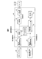
- FIG. 1 is a block diagram of a machine tool control apparatus according to a first embodiment of the present invention.
- FIG. It is a side view showing an example of a machine tool to which the present invention is applied. It is a perspective view which shows an example of the workpiece
- FIG. 8 is a perspective view showing reversal marks formed by reversal of the X-axis and Y-axis servo motors when the workpiece of FIG. 7 is processed by the conventional technique. It is a top view of the workpiece
- work of FIG. FIG. 8 is a perspective view showing a reversal mark formed by reversal of a Z-axis servomotor when the workpiece of FIG. 7 is machined by a conventional technique. It is a top view of the workpiece
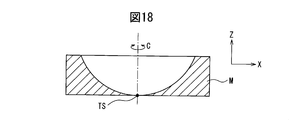
- FIG. 17 is a perspective view showing a reversal mark formed by reversal of a Z-axis servomotor when the workpiece of FIG. 16 is machined by a conventional technique. It is sectional drawing which follows the arrow line XVIII-XVIII of FIG.
- FIG. 17 is a schematic cross-sectional view showing positions of inversion marks formed when the workpiece of FIG. 16 is processed by the processing method of the present invention.
- FIG. 17 is a schematic cross-sectional view showing dispersion of inversion marks formed when the work of FIG. 16 is processed by the processing method of the present invention.
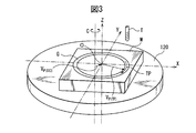
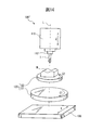
- FIG. 2 shows an example of a machine tool to which the present invention is applied.
- a machine tool 100 according to a preferred embodiment of the present invention constitutes a vertical machining center, and includes a bed 102 as a base fixed to the floor of a factory, a front portion of the bed 102 (in FIG. 2).
- Y-axis slider 106 provided to be movable in the front-rear direction or Y-axis direction (left-right direction in FIG. 2) on the upper surface of the left-side portion), the rotary table 120 attached to the upper surface of Y-axis slider 106,
- the column 104 fixed to the upper surface of the bed 102 (in FIG.
- a spindle head 110 is mounted on the front surface of the shaft slider 108 and the X-axis slider 108 so as to be movable in the vertical direction or the Z-axis direction and rotatably supports the spindle 112. It is.
- the Y-axis slider 106 is provided so as to reciprocate along a pair of Y-axis guide rails (not shown) extending in the horizontal Y-axis direction (left-right direction in FIG. 2) on the upper surface of the bed 102.
- the bed 102 includes a ball screw (not shown) extending in the Y-axis direction as one Y-axis feeding device that reciprocates the Y-axis slider 106 along the Y-axis guide rail, and one end of the ball screw.
- a linked Y-axis servo motor 116 is provided, and a nut (not shown) that engages with the ball screw is attached to the Y-axis slider 106.
- the Y-axis slider 106 is also attached with a Y-axis scale (not shown) for measuring the coordinate position of the Y-axis slider 106 in the Y-axis direction in the Y-axis direction.
- the spindle head 110 supports the spindle 112 so as to be rotatable around a central axis L extending in the vertical direction parallel to the Z axis.
- the main shaft 112 is formed with a tool mounting hole (not shown) for mounting the rotary tool T at a tip portion facing the Y-axis slider 106.
- the spindle head 110 has a servo motor (not shown) that rotationally drives the spindle 112.
- the servo motor can be attached to the outside of the housing of the spindle head 110, but a stator coil (not shown) is provided on the inner surface of the housing of the spindle head 110, and a rotor coil (not shown) is provided on the spindle 112. And it is good also as what is called a built-in motor.
- the X-axis slider 108 is provided so as to reciprocate along a pair of X-axis guide rails (not shown) extending in the X-axis direction on the front surface of the upper portion of the column 104.
- the column 104 is connected to a ball screw (not shown) extending in the X-axis direction and one end of the ball screw as an X-axis feeding device that reciprocates the X-axis slider 108 along the X-axis guide rail.
- An X-axis servo motor 114 is provided, and a nut (not shown) that engages with the ball screw is attached to the X-axis slider 108.
- An X-axis scale (not shown) for measuring the coordinate position of the X-axis slider 108 in the X-axis direction is also attached to the column 104.
- the spindle head 110 is provided so as to reciprocate along a pair of Z-axis guide rails extending in the Z-axis direction (vertical direction in FIG. 2) on the front surface of the X-axis slider 108.
- the X-axis slider 108 includes a ball screw (not shown) extending in the Z-axis direction as one Z-axis feeding device that reciprocates the spindle head 110 along the Z-axis guide rail, and one end of the ball screw.
- a coupled Z-axis servomotor 118 is provided, and a nut (not shown) that engages with the ball screw is attached to the spindle head 110.
- a Z-axis scale (not shown) for measuring the coordinate position of the spindle head 110 in the Z-axis direction is also attached to the X-axis slider 108.
- the rotary tool T is fed along its central axis by a Z-axis feeder.
- the turntable 120 is provided so as to be rotatable around an axis parallel to the Z axis, has a work mounting surface for mounting the work M, and forms a C-axis feed device that is a rotary feed shaft around the axis.
- the Y-axis slider 106 includes a C-axis servo motor 122 that rotationally drives the rotary table 120 and a rotation sensor (not shown) such as a rotary encoder that measures the rotational position of the rotary table 120.
- the X-axis servo motor 114, the Y-axis servo motor 116, the Z-axis servo motor 118, the C-axis servo motor 122, the X-axis scale, the Y-axis scale, the Z-axis scale, and the rotation sensor are added to the NC device 10 that controls the machine tool 100. It is connected.
- the NC device 10 controls the power (current value) supplied to the X-axis servo motor 114, the Y-axis servo motor 116, the Z-axis servo motor 118, and the C-axis servo motor 122.
- the reversal mark is a defective portion such as a bite or protrusion generated on the processing surface.
- the sign of the tangent slope is used. This occurs when the feed direction of the linear feed axes of the X, Y, and Z axes is reversed.
- the inversion marks are formed on the surface of the circular groove G of the workpiece M on the X axis and Y axis.
- the reversal marks are dispersed over the entire processing surface, instead of suppressing the generation of the reversal marks. It is preferable to use the conventional control for reducing the size of the reversal mark (for example, the invention of Patent Document 1 described above) in combination.
- the NC apparatus 10 includes a reading interpretation unit 12, an interpolation unit 14, and a servo control unit 16.
- the reading / interpreting unit 12 reads and interprets a machining program from a tool path generation device 20 described later, and outputs a movement command to the interpolation unit 14.
- This movement command includes the feed amount and feed speed in the X-axis, Y-axis, Z-axis, and C-axis directions.
- Interpolation unit 14 performs interpolation calculation on the received X-axis, Y-axis, Z-axis, and C-axis movement commands, and outputs a position command that matches the interpolation function and feed speed to servo control unit 16.
- the servo control unit 16 drives the X-axis, Y-axis, Z-axis, and C-axis feed axes of the machine tool 100 from the received X-axis, Y-axis, Z-axis, and C-axis position commands. Is supplied to the X-axis, Y-axis, Z-axis, and C-axis servomotors 114, 116, 118, and 122.
- the tool path generation device 20 includes a synthesis program calculation unit 22, an inversion position simulation unit 24, a display unit 26, and an interference determination unit 28.
- a machining program 30 for machining the workpiece M and a reverse position distribution program 32 for rotating and feeding the workpiece M in the C-axis direction are input to the synthesis program calculation unit 22.
- the machining program 30 and the inverted position distribution program 32 are input to the synthesis program calculation unit 22 via a computer network such as a LAN from a machining program generation device (not shown) such as a CAM (Computer Aided Manufacturing) device. Can do.
- the tool path generation device 20 is provided with an input device (not shown) such as a keyboard or a touch panel, and an operator inputs the machining program 30 and the reverse position distribution program 32 from the input device to the synthesis program calculation unit 22.
- the machining program 30 and the reverse position distribution program 32 input to the synthesis program calculation unit 22 may be edited.
- the machining program 30 is a program that can machine the workpiece M independently, and is a program that controls the minimum feed axis necessary for machining the workpiece M.
- the feed axis controlled by this machining program is an essential feed axis.
- the reverse position distribution program is a program for controlling a surplus feed axis that is a feed axis that is different from the essential feed axis and cannot process the workpiece M by itself.
- the synthesis program calculation unit 22 generates a synthesis program based on the machining program 30 and the reverse position distribution program 32.
- the synthesis program is output to the reading interpretation unit 12 of the NC apparatus 10.
- the synthesis program is also sent to the reversal position simulation unit 24, and the reversal position simulation unit 24 simulates the machining surface created on the workpiece M by calculation.
- the occurrence position of the inversion mark can be displayed on the display unit 26 as a graphic and / or numerical value.
- the size of the reversal mark may be simulated and displayed.
- the interference determination unit 28 determines whether or not the part where the cutting edge of the tool T is not present or the shank or cutter body interferes with the workpiece M based on the synthesis program generated by the synthesis program calculation unit 22 or the tool T And whether or not the stationary components of the machine tool 100 interfere with each other. As a result, when it is determined that there is no interference, the synthesis program can be executed. On the contrary, if it is determined that interference is caused by executing the synthesis program, the synthesis program becomes inexecutable and at the same time, an interference warning is displayed on the display unit 26.
- a machining program 30 for forming the circular groove G in the workpiece M and a reverse position distribution program 32 for rotationally feeding the rotary table 120 in the C-axis direction are input to the synthesis program calculation unit 22 of the tool path generation device 20.
- the machining program 30 is a machining program including a process of machining the rotary tool T relative to the workpiece M so as to draw a curve by simultaneously controlling only two linear feed axes.
- the machining program 30 controls the ball end mill T as a rotating tool to control two linear motion feed axes of the X axis and the Y axis as essential feed axes, and the ball end mill T is turned into one circular shape.
- Move relative to the workpiece M along the tool path TP then give the ball end mill T pick feed in the X-axis and Z-axis directions, and control the two linear feed axes of the X-axis and Y-axis to be adjacent
- a machining program for moving the ball end mill T relative to the workpiece M along the next circular tool path TP to form one circular groove G having a semicircular cross section on the upper surface of the workpiece M. is there.
- the circular tool path TP is a large number of concentric circles centered on O, and the ball end mill T finishes the circular groove G by making many turns along the circular tool path TP.
- the reversal position distribution program 32 disperses reversal marks generated during the machining of the workpiece M over the entire machining surface, so as not to concentrate on a specific part.
- the rotary table 120 is rotated in the C-axis direction, which is a rotation feed axis around an axis parallel to the Z-axis perpendicular to the X-axis and the Y-axis that moves the ball end mill T relative to the workpiece M along the path TP (workpiece).
- This is a program for rotating and feeding M in the C-axis direction.
- the C axis provides at least one surplus feed axis.
- the C-axis direction can be only clockwise or counterclockwise, or a mixture of clockwise and counterclockwise.
- the inversion position distribution program 32 can include a program for controlling the Z-axis and the W-axis, and a program for reciprocating or swinging the peristaltic member in the B-axis direction.
- the synthesis program calculation unit 22 analyzes the machining program 30 and extracts a code that defines the circular tool path TP for forming the circular groove G on the upper surface of the workpiece M. Further, the synthesis program calculation unit 22 analyzes the reverse position distribution program 32 and extracts a C-axis feed code. Further, the synthesis program calculation unit 22 changes the origin of the circular tool path TP for the circular groove G in the machining program 30 from the extracted C-axis feed code, for example, the circular tool path TP in the example of FIG.
- the magnitude of the position vector V P (CO) corresponds to the amount of deviation between the center of the C axis and the center O of the circular groove G.
- the synthesis program calculation unit 22 outputs the synthesis program to the reading interpretation unit 12 and the inversion position simulation unit 24 of the NC device 10.
- the synthesis program calculation unit 22 corresponds to a superimposition unit described in claim 8.
- the NC apparatus 10 controls the X-axis, Y-axis, Z-axis, and C-axis servomotors 114, 116, 118, and 122 based on the synthesis program from the synthesis program calculation unit 22.
- the reversal position simulation unit 24 displays the machining surface formed on the workpiece M and the position of the reversal mark generated on the machining surface based on the synthesis program from the synthesis program calculation unit 22 in graphics and / or numerical values.
- the X, Y, and C axis positions on the tool path when the X axis servo motor 114 or the Y axis servo motor 116 is reversed are calculated and displayed.
- the reversal mark is hatched in FIG.
- the noise occurs intensively along four boundaries QB between the quadrants with respect to the center O of the circular groove G in the XY plane.
- the inversion marks QP are distributed substantially uniformly along the surface of the circular groove G as shown in FIG.
- a circular tool path TP excluding a pick feed portion in a machining program 30 for machining a circular groove G having an inner diameter of 49.6 mm and a groove width of 5.7 mm using a ball end mill having an outer diameter of ⁇ 1.5 mm is centered on O. 300 concentric circles, and while the tool T circulates along the circular tool path TP 300 times, four reversal traces per round occur little by little for each adjacent circular tool path TP.
- the NC device 40 includes first and second reading interpretation units 42 and 44, a superimposition unit 46, an interpolation unit 48, an inversion position simulation unit 50, a servo control unit 52, a display unit 54, and an interference determination unit 56. .
- the first reading / interpreting unit 42 reads and interprets the machining program 30 and outputs a first movement command to the superimposing unit 46.
- This movement command includes the feed amount and feed speed in the three orthogonal directions of the X, Y, and Z axes.
- the second reading interpretation unit 44 reads and interprets the inverted position distribution program 32 and outputs a second movement command to the superposition unit 46.
- This second movement command includes the direction and speed of rotation feed of the C axis.
- the superimposing unit 46 superimposes the movement commands output from the first and second reading interpretation units 42 and 44. That is, as in the first embodiment, for example, in the example of FIG. 3, the position vector V P (TP) representing the circular tool path TP is the position of the center O of the circular groove G viewed from the central axis direction of the C axis.
- the superimposed movement command to which the vector VP (CO) is added and the C-axis rotational movement command are output to the interpolation unit 48.
- the interpolation unit 48 performs an interpolation calculation on each of the received superimposed movement command and C-axis rotational movement command, and outputs a position command to the servo control unit 52.
- the servo control unit 52 drives the X-axis, Y-axis, Z-axis, and C-axis feed axes of the machine tool 100 from the received X-axis, Y-axis, Z-axis, and C-axis position commands. Is output to the X-axis, Y-axis, Z-axis, and C-axis servomotors 114, 116, 118, and 122.
- the superposition movement command from the superposition unit 46 is simulated by the reversal position simulation unit 50 prior to the actual machining, and the operation of displaying the position where the reversal mark is generated on the display unit 54 is the same as in the first embodiment. It is.
- the interference determination part 56 acts similarly to the interference determination part 28 of the first embodiment.
- the superimposing unit, the reverse position simulation unit, and the display unit are provided on the tool path generation device 20, that is, the CAM device side as in the first embodiment, and on the NC device side as in the second embodiment. There are cases.
- the present invention is applied to the processing of a mold for forming an O-ring, but the present invention is not limited to this.
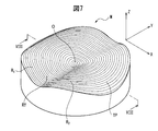
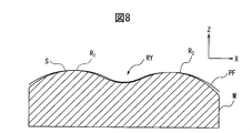
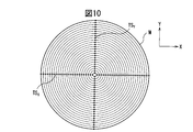
- the present invention can also be applied to form a three-dimensional curved surface as shown in FIGS. 7 and 8, the workpiece M has a top surface or a machining surface S having a smooth waveform.
- the upper surface or the processed surface S has a Y-axis direction so as to intersect the center O in a cross section cut along a plane parallel to the plane including the X axis and the Z axis (XZ plane).
- ridges R1 and R2 extending in the Y-axis direction on both sides of the recess RY.
- the X-axis, Y-axis, and Z-axis linear motion feed axes as the necessary feed axes of such a work M are controlled to bring the tool T into the work M along a plurality of concentric tool paths TP as shown in FIG.
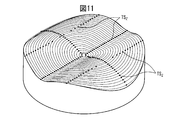
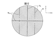
- the rotation direction of the Z-axis feed motor in addition to the reversal marks TSx and TSy (FIGS. 9 and 10) formed when the rotation directions of the X-axis and Y-axis feed motors are reversed. Is inverted, a reversal mark TSz as shown in FIGS. 11 and 12 is formed.
- the reversal marks TSx and TSy shown in FIGS. 9 and 10 can be dispersed in the direction of the C-axis rotational feed by controlling the C-axis.
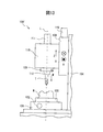
- the reversal marks TSz formed when the Z-axis feed motor is reversed cannot be dispersed by the C-axis control. Therefore, in order to disperse the reversal marks TSz, in the embodiment shown in FIG. 13, in addition to the Z-axis feed device, as an extra feed shaft that moves the quill 109 up and down relatively in the vertical direction with respect to the spindle head 110. It has a W-axis feeder.
- a machine tool 100 ′ is provided with a ball screw (not shown) and a W-axis servo motor 111 connected to one end of the ball screw as a W-axis feed device that provides an extra feed shaft.
- the nut 109 (not shown) that engages with the ball screw is attached to the quill 109.
- a W-axis scale (not shown) for measuring the coordinate position of the quill 109 in the W-axis direction is also attached to the spindle head 110.
- the ball end mill T as a rotary tool is controlled by controlling three linear feed axes of the X axis, the Y axis, and the Z axis.
- the ball end mill T is moved relative to the workpiece M along one tool path TP, and then a pick feed PF is given to the ball end mill T in the X-axis and Z-axis directions.
- the ball end mill T is moved relative to the workpiece M along the next adjacent tool path TP by controlling two linear feed axes, and the upper surface or the machining surface S having a smooth waveform on the workpiece M is repeated. It is a processing program for forming.
- Each tool path TP has a circular shape when projected onto a plane (XY plane) perpendicular to the Z axis. That is, the X axis and the Y axis are controlled to feed the ball end mill T along the circumference, and the Z axis is controlled so that the tip of the ball end mill T follows the corrugated upper surface S.
- the reversal position distribution program 32 disperses reversal marks generated during the machining of the workpiece M over the entire machining surface and prevents the rotation table 120 from being concentrated on a specific part.
- a machine tool 100 ′′ includes first and second rotation tables that are coaxially provided with a rotary table 120 that forms a C-axis as an extra feed shaft.
- the first and second rotary tables 121 and 123 are in opposite directions, and in the example of FIG. 14, the first rotary table 121 is in the clockwise direction C1.
- the second rotary table 123 rotates in the counterclockwise direction C2. If the command value to the first rotary table 121 is c1, and the command value to the second rotary table 123 is c2.
- C1 + c2 is a command value for the C-axis, and is a rotation amount of the workpiece M.
- the first and second rotary tables 121, 1 that are provided with the rotary table 120 coaxially and rotate in opposite directions to each other.
- the C-axis By forming the 3, without reversing the direction of rotation of the motor, it is possible to control the C-axis, thereby enabling machining without causing inversion marks.
- the reversing marks generated on the circular groove G and the corrugated machining surface are dispersed by rotating the C-axis that is the rotary feed shaft around the axis parallel to the Z-axis.
- the B-axis is the rotational feed axis about an axis parallel to the Y axis.
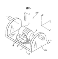
- FIG. 15 shows an example in which a semi-cylindrical outer peripheral surface S having a central axis R parallel to the Y axis is processed into a workpiece M using a ball end mill as the rotary tool T.
- Rotating table 120 of the machine tool 100 3 is attached to the upper surface of the swinging member 130 which is mounted swingably around a B axis to Y-axis slider 106, the workpiece M on the upper surface of the turntable 120 is the center axis It is attached so that R is parallel to the Y axis.
- the ball end mill of the Z-axis as the rotating tool T Y axis direction of the pick-feed PF Is a machining program that feeds relative to the workpiece M along a plurality of arcs centered on the central axis R of the workpiece M parallel to the Y axis. That is, while machining along one of the plurality of arcs, the Y-axis feed device is fixed, and only the two linear feed axes of the X axis and the Z axis are controlled. Meanwhile, the C-axis is fixed.
- the inversion position distribution program 32 is a program for causing the peristaltic member 130 to perform a reciprocating rotation operation or a swing operation in the B-axis direction, which is a rotation feed shaft around an axis parallel to the Y-axis.
- the reversal marks are concentrated along a straight line parallel to the central axis R at the highest position on the outer surface of the workpiece M.
- the reversal marks are distributed substantially uniformly along the outer peripheral surface S of the workpiece M.
- the position of the inversion mark is used as the tool path.
- the adjacent tool path refers to a tool path for one round separated by a spiral lead.
- a recess R is formed on the upper surface of the rectangular parallelepiped block, for forming a workpiece M, such as lens mold It is effective for.
- the tool (ball end mill) T is controlled along a plurality of curved tool paths TP extending in the direction of the arrow PD along the concave bottom surface (machining surface S) by controlling the Y axis and the Z axis.
- a reversal mark TS is formed on the machining surface S at the lowest position in each tool path TP, and the reversal marks TS are arranged in a line in the X-axis direction. Even if the C-axis is rotated as in the above-described embodiment, the position of the reversal mark TS does not change as shown in FIG.
- the inversion marks TS can be dispersed in the C-axis direction within the region D.
- machining program 30 A machining program that feeds a ball end mill with the X axis, Y axis, and Z axis as rotary tools T relative to the workpiece M along a plurality of arc curves in the Y axis direction while giving a pick feed PF in the X axis direction. is there.
- the reverse position distribution program 32 is a program for tilting the B axis by a predetermined angle ⁇ B and rotating the C axis a predetermined number of times.
- the tool path when the machining program 30 and the reverse position distribution program 32 are overlapped is the simultaneous control of the four axes of the X axis, the Y axis, the Z axis, and the C axis.
- a curve and a pick feed in a direction orthogonal to the arrow PD are generated.
- the required feed axes are the three orthogonal axes of the X, Y, and Z axes
- the surplus feed axes are the two rotary feeds of the A axis or B axis and C axis. If it is an axis
Abstract
Description
第2の実施形態において、図1のNC装置10と工具経路生成装置20は、2系統制御タイプのNC装置40によって置換されている。NC装置40は、第1と第2の読取解釈部42、44、重畳部46、補間部48、反転位置シミュレーション部50、サーボ制御部52、表示部54および干渉判定部56を具備している。 Next, a second embodiment of the machine tool control apparatus of the present invention will be described with reference to FIG.
In the second embodiment, the
12 読取解釈部
14 補間部
16 サーボ制御部
20 工具経路生成装置
22 合成プログラム演算部
24 反転位置シミュレーション部
26 表示部
30 加工プログラム
32 反転位置分散プログラム
100 工作機械
102 ベッド
104 コラム
110 主軸頭
112 主軸
120 回転テーブル DESCRIPTION OF
Claims (10)
- 工具とワークとを相対移動させてワークを加工する加工方法において、
ワークの加工になくてはならない必須送り軸と、必須ではない少なくとも1つの余剰送り軸を用い、工具経路ごとに送りモータの反転位置を分散させる、または送りモータの反転動作をなくしてワークを加工することを特徴とした加工方法。 In a machining method for machining a workpiece by relatively moving the tool and the workpiece,
Using the indispensable feed axis that is indispensable for machining the workpiece and at least one extra feed axis that is not indispensable, disperse the reversing position of the feed motor for each tool path or eliminate the reversing operation of the feed motor to machine the work The processing method characterized by doing. - 前記必須送り軸は、互いに直交するX軸、Y軸、Z軸の3つの直動送り軸でなり、前記余剰送り軸は、X軸、Y軸、Z軸と平行な軸線周りに回転するA軸、B軸、C軸のうち少なくとも1つの回転送り軸でなり、工具経路ごとに送りモータの反転位置を分散させる請求項1に記載の加工方法。 The essential feed shaft is composed of three linear motion feed shafts of X axis, Y axis, and Z axis orthogonal to each other, and the surplus feed shaft is rotated around an axis parallel to the X axis, Y axis, and Z axis. The machining method according to claim 1, comprising at least one rotary feed shaft among the shaft, the B-axis, and the C-axis, wherein the reverse position of the feed motor is dispersed for each tool path.
- 前記必須送り軸は、互いに直交するX軸、Y軸、Z軸の3つの直動送り軸でなり、前記余剰送り軸は、X軸、Y軸、Z軸と平行な∪軸、∨軸、W軸のうち少なくとも1つの直動送り軸でなり、工具経路ごとに送りモータの反転位置を分散させる請求項1に記載の加工方法。 The essential feed shaft is composed of three linear feed shafts of X axis, Y axis, and Z axis orthogonal to each other, and the surplus feed shaft is a saddle shaft, a saddle shaft parallel to the X axis, Y axis, Z axis, The machining method according to claim 1, comprising at least one linear feed axis among the W axes, wherein the reverse positions of the feed motor are dispersed for each tool path.
- 前記必須送り軸は、互いに直交するX軸、Y軸、Z軸の3つの直動送り軸でなり、前記余剰送り軸は、X軸、Y軸、Z軸と平行な軸線周りに回転するA軸、B軸、C軸のうち少なくとも1つの回転送り軸でなり、前記余剰送り軸は、同軸上に設けられ互いに反対方向に回転する2つの送りモータを含んでいる請求項1に記載の加工方法。 The essential feed shaft is composed of three linear motion feed shafts of X axis, Y axis, and Z axis orthogonal to each other, and the surplus feed shaft is rotated around an axis parallel to the X axis, Y axis, and Z axis. The machining according to claim 1, comprising at least one rotary feed shaft among a shaft, a B-axis, and a C-axis, wherein the surplus feed shaft includes two feed motors provided coaxially and rotating in opposite directions. Method.
- 前記必須送り軸により曲線状の工具経路を形成し、前記余剰送り軸により前記工具経路ごとに送りモータの反転位置を分散させる請求項2に記載の加工方法。 3. The machining method according to claim 2, wherein a curved tool path is formed by the essential feed axis, and a reverse position of a feed motor is dispersed for each of the tool paths by the surplus feed axis.
- ワークを加工するための工具経路に沿った前記必須送り軸の動作と、前記工具経路ごとに送りモータの反転位置を分散させる前記余剰送り軸の動作とを、前記工具経路の前記ワークに対する相対位置が変化しないように重畳させる請求項2に記載の加工方法。 Relative position of the tool path with respect to the workpiece, the operation of the essential feed axis along the tool path for machining the workpiece, and the operation of the surplus feed axis that disperses the reverse position of the feed motor for each tool path. The processing method according to claim 2, wherein the superposition is performed so as not to change.
- 前記必須送り軸により曲線状の工具経路を形成し、前記余剰送り軸がA軸またはB軸とC軸の2つの回転送り軸であり、A軸またはB軸を所定の回転角度に割り出してワークを傾け、その姿勢でワークをC軸方向に回転させ、前記工具経路の前記ワークに対する相対位置が変化しないように、前記必須送り軸の動作と前記余剰送り軸の動作とを重畳させる請求項2に記載の加工方法。 A curved tool path is formed by the essential feed axis, the surplus feed axis is two rotary feed axes of A axis or B axis and C axis, and the A axis or B axis is indexed at a predetermined rotation angle to work The operation of the essential feed shaft and the operation of the surplus feed shaft are superimposed so that the relative position of the tool path with respect to the work does not change by rotating the workpiece in the C-axis direction in the posture. The processing method as described in.
- ワークの加工になくてはならない必須送り軸と、必須ではない少なくとも1つの余剰送り軸を有し、工具とワークとを相対移動させてワークを加工する工作機械の制御装置であって、
前記必須送り軸による加工プログラムを実行する間、前記余剰送り軸の動作を含む反転位置分散プログラムを実行し、ワークの加工面における送りモータの反転位置を分散させる重畳部を具備することを特徴とした工作機械の制御装置。 A control device for a machine tool, which has an indispensable feed axis that is indispensable for machining a workpiece and at least one extra feed axis that is not essential, and processes the workpiece by relatively moving the tool and the workpiece,
A reversing position distribution program including the operation of the surplus feed axis is executed while the machining program by the essential feed axis is executed, and a superposition unit is provided for dispersing the reversing position of the feed motor on the machining surface of the workpiece. Machine tool control device. - 前記重畳部により前記加工プログラムの動作と反転位置分散プログラムの動作とが重畳されたとき、前記加工面における送りモータの反転位置を工具経路ごとに演算する反転位置シミュレーション部と、演算された送りモータの反転位置を表示する表示部とをさらに具備する請求項8に記載の工作機械の制御装置。 When the operation of the machining program and the operation of the reversal position distribution program are superimposed by the superimposing unit, a reversing position simulation unit that calculates the reversing position of the feed motor on the machining surface for each tool path, and the calculated feed motor The machine tool control device according to claim 8, further comprising a display unit configured to display a reverse position of the machine tool.
- 工具の切刃がない部分とワークとの干渉チェックを行う干渉判定部をさらに具備する請求項9に記載の工作機械の制御装置。 The machine tool control device according to claim 9, further comprising an interference determination unit that performs an interference check between a part having no cutting edge of the tool and the workpiece.
Priority Applications (5)
| Application Number | Priority Date | Filing Date | Title |
|---|---|---|---|
| JP2015559729A JP6076507B2 (en) | 2014-01-31 | 2014-08-13 | Machining method and machine tool control device |
| KR1020167014439A KR101954295B1 (en) | 2014-01-31 | 2014-08-13 | Machining Method and Machine-Tool Control Device |
| US15/115,546 US10146204B2 (en) | 2014-01-31 | 2014-08-13 | Machining method and a control device for a machine tool |
| CN201480072374.2A CN105917282B (en) | 2014-01-31 | 2014-08-13 | The control device of processing method and lathe |
| EP14881214.2A EP3101498A4 (en) | 2014-01-31 | 2014-08-13 | Machining method and machine-tool control device |
Applications Claiming Priority (2)
| Application Number | Priority Date | Filing Date | Title |
|---|---|---|---|
| JPPCT/JP2014/052316 | 2014-01-31 | ||
| PCT/JP2014/052316 WO2015114811A1 (en) | 2014-01-31 | 2014-01-31 | Cutting method and control device |
Publications (1)
| Publication Number | Publication Date |
|---|---|
| WO2015114861A1 true WO2015114861A1 (en) | 2015-08-06 |
Family
ID=53756422
Family Applications (2)
| Application Number | Title | Priority Date | Filing Date |
|---|---|---|---|
| PCT/JP2014/052316 WO2015114811A1 (en) | 2014-01-31 | 2014-01-31 | Cutting method and control device |
| PCT/JP2014/071406 WO2015114861A1 (en) | 2014-01-31 | 2014-08-13 | Machining method and machine-tool control device |
Family Applications Before (1)
| Application Number | Title | Priority Date | Filing Date |
|---|---|---|---|
| PCT/JP2014/052316 WO2015114811A1 (en) | 2014-01-31 | 2014-01-31 | Cutting method and control device |
Country Status (6)
| Country | Link |
|---|---|
| US (1) | US10146204B2 (en) |
| EP (1) | EP3101498A4 (en) |
| JP (1) | JP6076507B2 (en) |
| KR (1) | KR101954295B1 (en) |
| CN (1) | CN105917282B (en) |
| WO (2) | WO2015114811A1 (en) |
Cited By (2)
| Publication number | Priority date | Publication date | Assignee | Title |
|---|---|---|---|---|
| WO2018003813A1 (en) * | 2016-06-28 | 2018-01-04 | コマツNtc株式会社 | Machine tool, method for manufacturing processed article, and processing system |
| JP2020110922A (en) * | 2016-06-28 | 2020-07-27 | 株式会社小松製作所 | Grinding device, work-piece manufacturing method, and grinding system |
Families Citing this family (7)
| Publication number | Priority date | Publication date | Assignee | Title |
|---|---|---|---|---|
| JP6514876B2 (en) * | 2014-10-27 | 2019-05-15 | オークマ株式会社 | Control method of feed axis in machine tool and machine tool |
| DE112016007167B4 (en) * | 2016-10-04 | 2022-09-15 | Mitsubishi Electric Corporation | Numerical control device |
| JP6499707B2 (en) * | 2017-04-03 | 2019-04-10 | ファナック株式会社 | Simulation device, program generation device, control device, and computer display method |
| JP6599920B2 (en) * | 2017-04-18 | 2019-10-30 | ファナック株式会社 | Machine tool controller for rocking cutting |
| JP7000303B2 (en) * | 2018-12-19 | 2022-01-19 | ファナック株式会社 | Numerical control device, numerical control machine system, machining simulation device, and machining simulation method |
| US20230044441A1 (en) * | 2020-01-23 | 2023-02-09 | Fanuc Corporation | Workpiece machining method |
| CN114326372B (en) * | 2021-12-08 | 2023-08-04 | 北京理工大学 | Non-smooth feedback optimal tracking control method of position servo system |
Citations (6)
| Publication number | Priority date | Publication date | Assignee | Title |
|---|---|---|---|---|
| JPH07110717A (en) * | 1993-08-19 | 1995-04-25 | Fanuc Ltd | Motor control system |
| JP2558580B2 (en) | 1992-10-23 | 1996-11-27 | 株式会社牧野フライス製作所 | Method and apparatus for controlling acceleration in servo system |
| JP2004234205A (en) * | 2003-01-29 | 2004-08-19 | Mitsubishi Electric Corp | Numerical controller |
| JP2010049599A (en) * | 2008-08-25 | 2010-03-04 | Tokyo Univ Of Agriculture & Technology | Machine tool |
| JP2011022898A (en) | 2009-07-17 | 2011-02-03 | Doshisha | Cutting method for work material |
| JP2013206342A (en) | 2012-03-29 | 2013-10-07 | Makino Milling Mach Co Ltd | Control device for machine tool and machining method for work by rotary tool |
Family Cites Families (7)
| Publication number | Priority date | Publication date | Assignee | Title |
|---|---|---|---|---|
| JP3478946B2 (en) * | 1997-07-02 | 2003-12-15 | 東芝機械株式会社 | Servo adjustment method and device |
| JP2000061777A (en) * | 1998-08-25 | 2000-02-29 | Makino Milling Mach Co Ltd | Curved face cutting method and device thereof |
| EP1114694B1 (en) * | 1999-02-26 | 2004-04-28 | Mori Seiki Co., Ltd. | Machine tool |
| JP4316850B2 (en) * | 2002-09-26 | 2009-08-19 | 森精機興産株式会社 | Machining method in complex machine tool |
| JP5471159B2 (en) * | 2009-08-24 | 2014-04-16 | 株式会社ジェイテクト | Machine tool controller |
| JP5373675B2 (en) * | 2010-03-17 | 2013-12-18 | シチズンホールディングス株式会社 | Machine Tools |
| CN102947037B (en) * | 2010-06-18 | 2015-01-28 | 株式会社牧野铣床制作所 | Method for grinding/machining gear and machining device |
-
2014
- 2014-01-31 WO PCT/JP2014/052316 patent/WO2015114811A1/en active Application Filing
- 2014-08-13 EP EP14881214.2A patent/EP3101498A4/en not_active Ceased
- 2014-08-13 JP JP2015559729A patent/JP6076507B2/en active Active
- 2014-08-13 CN CN201480072374.2A patent/CN105917282B/en active Active
- 2014-08-13 WO PCT/JP2014/071406 patent/WO2015114861A1/en active Application Filing
- 2014-08-13 US US15/115,546 patent/US10146204B2/en active Active
- 2014-08-13 KR KR1020167014439A patent/KR101954295B1/en active IP Right Grant
Patent Citations (6)
| Publication number | Priority date | Publication date | Assignee | Title |
|---|---|---|---|---|
| JP2558580B2 (en) | 1992-10-23 | 1996-11-27 | 株式会社牧野フライス製作所 | Method and apparatus for controlling acceleration in servo system |
| JPH07110717A (en) * | 1993-08-19 | 1995-04-25 | Fanuc Ltd | Motor control system |
| JP2004234205A (en) * | 2003-01-29 | 2004-08-19 | Mitsubishi Electric Corp | Numerical controller |
| JP2010049599A (en) * | 2008-08-25 | 2010-03-04 | Tokyo Univ Of Agriculture & Technology | Machine tool |
| JP2011022898A (en) | 2009-07-17 | 2011-02-03 | Doshisha | Cutting method for work material |
| JP2013206342A (en) | 2012-03-29 | 2013-10-07 | Makino Milling Mach Co Ltd | Control device for machine tool and machining method for work by rotary tool |
Non-Patent Citations (1)
| Title |
|---|
| See also references of EP3101498A4 * |
Cited By (3)
| Publication number | Priority date | Publication date | Assignee | Title |
|---|---|---|---|---|
| WO2018003813A1 (en) * | 2016-06-28 | 2018-01-04 | コマツNtc株式会社 | Machine tool, method for manufacturing processed article, and processing system |
| JP2020110922A (en) * | 2016-06-28 | 2020-07-27 | 株式会社小松製作所 | Grinding device, work-piece manufacturing method, and grinding system |
| US11458584B2 (en) | 2016-06-28 | 2022-10-04 | Komatsu Ntc Ltd. | Machine tool, machined-object manufacturing method, and machining system |
Also Published As
| Publication number | Publication date |
|---|---|
| JP6076507B2 (en) | 2017-02-08 |
| CN105917282B (en) | 2019-08-06 |
| KR20160078483A (en) | 2016-07-04 |
| JPWO2015114861A1 (en) | 2017-03-23 |
| WO2015114811A1 (en) | 2015-08-06 |
| EP3101498A1 (en) | 2016-12-07 |
| US10146204B2 (en) | 2018-12-04 |
| KR101954295B1 (en) | 2019-03-05 |
| EP3101498A4 (en) | 2017-10-25 |
| US20170185064A1 (en) | 2017-06-29 |
| CN105917282A (en) | 2016-08-31 |
Similar Documents
| Publication | Publication Date | Title |
|---|---|---|
| JP6076507B2 (en) | Machining method and machine tool control device | |
| JP5219974B2 (en) | Processing control device, laser processing device and laser processing system | |
| US10569348B2 (en) | Groove-forming method, control device for machine tool and tool path generating device | |
| JP5670517B2 (en) | Impeller with wings composed of surfaces made of straight elements and method of machining the same | |
| WO2014002228A1 (en) | Control device for machine tool and machine tool | |
| JP5881850B2 (en) | Machine tool control device and machine tool | |
| JP2005071016A (en) | Numerical control device | |
| JP5881843B2 (en) | Tool path generation method, machine tool control apparatus, and tool path generation apparatus | |
| CN208068016U (en) | Rotating mechanism and its grinding machine | |
| JP6008294B2 (en) | Non-circular machining method by turning | |
| WO2018011990A1 (en) | Machining program generation device and machining method | |
| JP2013210926A (en) | Groove forming method | |
| JP2000263366A (en) | Machining tool | |
| JP7208151B2 (en) | Machine Tools | |
| JP2015182170A (en) | Machine tool | |
| Sudo | Advanced Control Technologies for 5-Axis Machining. | |
| JP5721506B2 (en) | Machine Tools | |
| US20230115138A1 (en) | Machine tool and method of deciding tool moving path | |
| JPH068059A (en) | Electric discharge machine | |
| CN106141852B (en) | The control method of numerical control inclined shaft grinding machine and numerical control inclined shaft grinding machine | |
| Lin et al. | Trajectory analyses for five-axis machine tools | |
| JP2022115435A (en) | Stability limit analyzer | |
| JP2013094829A (en) | Machining method and machine |
Legal Events
| Date | Code | Title | Description |
|---|---|---|---|
| 121 | Ep: the epo has been informed by wipo that ep was designated in this application |
Ref document number: 14881214 Country of ref document: EP Kind code of ref document: A1 |
|
| ENP | Entry into the national phase |
Ref document number: 2015559729 Country of ref document: JP Kind code of ref document: A |
|
| ENP | Entry into the national phase |
Ref document number: 20167014439 Country of ref document: KR Kind code of ref document: A |
|
| WWE | Wipo information: entry into national phase |
Ref document number: 15115546 Country of ref document: US |
|
| NENP | Non-entry into the national phase |
Ref country code: DE |
|
| REEP | Request for entry into the european phase |
Ref document number: 2014881214 Country of ref document: EP |
|
| WWE | Wipo information: entry into national phase |
Ref document number: 2014881214 Country of ref document: EP |