以下、巻鉄心および巻鉄心の製造方法に係る複数の実施形態について図面を参照しながら説明する。なお、各実施形態で実質的に同一の要素には同一の符号を付し、説明を省略する。
Hereinafter, a plurality of embodiments relating to a wound core and a method for manufacturing the wound core will be described with reference to the drawings. In addition, the same code | symbol is attached | subjected to the substantially same element in each embodiment, and description is abbreviate | omitted.
(第1実施形態)
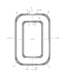
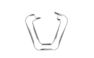
例えば図1に示す巻鉄心10は、図示しない珪素鋼板を切断することにより得られた複数枚の鉄心材10aが巻回された構成である。この巻鉄心10は、中心にほぼ矩形の窓部11を有する。また、巻鉄心10は、窓部11の4隅に設けられる4つのコーナ部12と、これらコーナ部12を除く4つの辺部13を有する。辺部13は、コーナ部12間を繋ぐ。この場合、辺部13は、図示しない巻線が組み付けられる長辺部13aと、この長辺部13aよりも短い短辺部13bからなる。巻鉄心10を構成する複数枚の鉄心材10aは、一巻き分、つまりワンターン分ごとに珪素鋼板から切断されたものであり、従って、この場合、一巻ごとに1箇所の切断部を有している。そして、各鉄心材10aにおいて切断部が接合される部分、つまり、各鉄心材10aの両端部には接合部14が形成される。
(First embodiment)
For example, a wound iron core 10 shown in FIG. 1 has a configuration in which a plurality of iron core members 10a obtained by cutting a silicon steel plate (not shown) is wound. The wound iron core 10 has a substantially rectangular window 11 at the center. The wound core 10 has four corner portions 12 provided at four corners of the window portion 11 and four side portions 13 excluding these corner portions 12. The side portion 13 connects the corner portions 12. In this case, the side portion 13 includes a long side portion 13a to which a winding (not shown) is assembled, and a short side portion 13b shorter than the long side portion 13a. The plurality of iron core members 10a constituting the wound core 10 are cut from the silicon steel plate for one turn, that is, for one turn. Therefore, in this case, one turn portion is provided for each turn. ing. And the junction part 14 is formed in the part to which a cutting part is joined in each iron core material 10a, ie, the both ends of each iron core material 10a.
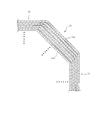
そして、例えば図2に示すように、巻鉄心10は、コーナ部12における鉄心材10aの占積率が辺部13における鉄心材10aの占積率よりも低くなっている。即ち、辺部13では鉄心材10aが密に積層されているが、コーナ部12では鉄心材10aが密に積層されておらず各鉄心材10a間に隙間を有する状態となっている。この場合、各鉄心材10aは、1枚毎に隙間を有している。なお、占積率とは、巻鉄心10の断面積に対し鉄心材10aが占める面積の割合を示すものであり、占積率が高いほど、各鉄心材10aが密に積層されていることを示す。
For example, as shown in FIG. 2, in the wound core 10, the space factor of the iron core material 10 a in the corner portion 12 is lower than the space factor of the iron core material 10 a in the side portion 13. That is, the iron core material 10a is densely laminated at the side portion 13, but the iron core material 10a is not densely laminated at the corner portion 12, and there is a gap between the iron core materials 10a. In this case, each iron core material 10a has a gap for each sheet. The space factor indicates the ratio of the area occupied by the iron core material 10a to the cross-sectional area of the wound iron core 10. The higher the space factor, the denser the core material 10a is laminated. Show.
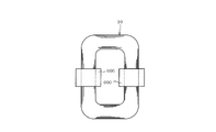
また、例えば図3に示すように、巻鉄心10は、所定枚の鉄心材10aごとに鉄心材群15a,15b,・・・を形成した構成である。即ち、最も窓部11側となる内側から所定枚の鉄心材10aが積層されるごとに1つの鉄心材群15a,15b,・・・が形成される。なお、1つの鉄心材群を形成する鉄心材10aの数は適宜変更して実施することができる。また、各鉄心材群を形成する鉄心材10aの数を適宜異ならせてもよい。
Further, as shown in FIG. 3, for example, the wound core 10 has a configuration in which core groups 15a, 15b,... Are formed for each predetermined number of cores 10a. That is, one iron core group 15a, 15b,... Is formed each time a predetermined number of iron cores 10a are stacked from the inner side that is closest to the window 11 side. In addition, the number of the iron core materials 10a which form one iron core material group can be changed and implemented suitably. Moreover, you may vary suitably the number of the iron core materials 10a which form each iron core material group.
また、各鉄心材群15a,15b,・・・に含まれる鉄心材10aは、切断部が接合される接合部14が相互に周方向にずれて階段状に位置するように巻回されている。また、例えば鉄心材群15bにおいて最も内側で巻回される鉄心材10aの接合部14の位置Pbは、当該鉄心材群15bの内側に隣接する鉄心材群15aにおいて最も内側で巻回される鉄心材10aの接合部14の位置Paとほぼあるいは完全に一致している。
Further, the iron core material 10a included in each of the iron core material groups 15a, 15b,... Is wound so that the joint portions 14 to which the cut portions are joined are displaced in the circumferential direction and positioned stepwise. . Further, for example, the position Pb of the joint portion 14 of the iron core material 10a wound on the innermost side in the iron core material group 15b is the iron core wound on the innermost side in the iron core material group 15a adjacent to the inner side of the iron core material group 15b. It almost or completely coincides with the position Pa of the joint portion 14 of the material 10a.
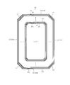
また、例えば図4に示すように、鉄心材群15bにおいて最も内側で巻回される鉄心材10aの周長Lbは、当該鉄心材群15bの内側に隣接する鉄心材群15aにおいて最も外側で巻回される鉄心材10aの周長Laよりも大きくなっている。この場合、周長Lbは、鉄心材10aの板厚dに応じた長さだけ長くなるように設定されており、例えば、次式(1)で示す関係が成立するようになっている。なお、「π」は円周率であり、「α」は適宜変更して設定することができる変数である。
Lb=La+πd+α・・・・・(1)
For example, as shown in FIG. 4, the circumferential length Lb of the iron core material 10 a wound on the innermost side in the iron core material group 15 b is wound on the outermost side in the iron core material group 15 a adjacent to the inner side of the iron core material group 15 b. It is larger than the circumferential length La of the iron core material 10a to be rotated. In this case, the circumferential length Lb is set to be longer by a length corresponding to the plate thickness d of the iron core material 10a. For example, the relationship represented by the following expression (1) is established. Note that “π” is a pi, and “α” is a variable that can be changed and set as appropriate.
Lb = La + πd + α (1)
次に、このようにコーナ部12の占積率が低くなった巻鉄心10を製造するための製造方法の一例について説明する。この製造方法は、珪素鋼板の切断工程、鉄心材の巻き取り工程、巻鉄心の成形工程、巻鉄心の焼鈍工程からなる。
Next, an example of a manufacturing method for manufacturing the wound core 10 in which the space factor of the corner portion 12 is lowered will be described. This manufacturing method includes a cutting process of a silicon steel sheet, a winding process of a core material, a forming process of a wound core, and an annealing process of the wound core.
≪珪素鋼板の切断工程≫
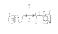
この工程では、例えば図5に示すように、製造装置100は、珪素鋼帯Mをフィーダ101によって順次送る構成である。そして、製造装置100は、順次送られる珪素鋼帯Mから、一巻き分、つまりワンターン分の鉄心材10aを切断刃102により順次切断する。
≪Silicon steel sheet cutting process≫
In this step, for example, as shown in FIG. 5, the manufacturing apparatus 100 is configured to sequentially feed the silicon steel strip M by the feeder 101. And the manufacturing apparatus 100 cuts the iron core material 10a for one volume, ie, one turn, sequentially from the silicon steel strip M sent sequentially by the cutting blade 102.
≪鉄心材の巻き取り工程≫
この工程では、例えば図5に示すように、製造装置100は、珪素鋼帯Mから得られた鉄心材10aを、円形の巻き取り型103に順次巻き取る。このとき、各鉄心材10aは、従来よりも緩く巻回される。なお、鉄心材10aを緩める程度は、目標とする巻鉄心10のコーナ部12の占積率に応じて、適宜調整して実施することができる。即ち、鉄心材10aを緩める程度を大きくするほど、コーナ部12の占積率をより低くすることができる。
≪Steel core winding process≫
In this step, for example, as shown in FIG. 5, the manufacturing apparatus 100 sequentially winds the iron core material 10 a obtained from the silicon steel strip M around a circular winding die 103. At this time, each iron core material 10a is wound more loosely than before. It should be noted that the degree of loosening the iron core material 10a can be appropriately adjusted according to the space factor of the corner portion 12 of the target wound iron core 10. That is, the space factor of the corner portion 12 can be further lowered as the degree of loosening the iron core material 10a is increased.
≪巻鉄心の成形工程≫
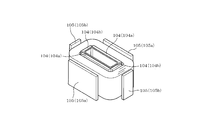
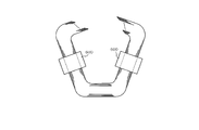
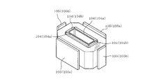
この工程では、例えば図6に示すように、巻き取られ積層された複数枚の鉄心材10aの内側の4箇所と外側の4箇所に成形型104,105を当てる。そして、成形型104,105により、鉄心材10aの4箇所を積層方向に沿って適宜プレスする。なお、プレスは、各鉄心材10aの切断部を接合した状態で行われる。鉄心材10aの4箇所が適宜プレスされることにより、プレスされる部分つまり成形型104,105によって挟まれた部分にそれぞれ辺部13が形成され、それ以外の部分、つまり、プレスされない部分にそれぞれコーナ部12が形成される。なお、「プレスされない部分」とは、換言すれば、成形型104,105によって挟まれていない部分である。
<< Molding process of wound core >>
In this step, for example, as shown in FIG. 6, the molds 104 and 105 are applied to the four inner portions and the four outer portions of the plurality of iron cores 10 a wound and stacked. And the four places of the iron core material 10a are suitably pressed along the lamination direction by the molds 104 and 105. In addition, a press is performed in the state which joined the cutting part of each iron core material 10a. By appropriately pressing the four locations of the iron core material 10a, the side portions 13 are formed in the portions to be pressed, that is, the portions sandwiched by the molds 104 and 105, respectively, and the other portions, that is, the portions that are not pressed, respectively. A corner portion 12 is formed. In addition, the “part that is not pressed” is, in other words, a part that is not sandwiched between the molds 104 and 105.
このとき、各鉄心材10aが従来よりも緩く巻回されていることから、プレスに際し、コーナ部12が形成される部分の鉄心材10aが適宜変形する。コーナ部12が適宜変形することにより、プレスに伴う鉄心材10aの変形が吸収される。よって、プレス後に、各鉄心材10aの切断部、換言すれば接合部14が開いてしまうことを防止することができる。
At this time, since each iron core material 10a is wound more loosely than before, the iron core material 10a in the portion where the corner portion 12 is formed is appropriately deformed during pressing. When the corner portion 12 is appropriately deformed, the deformation of the iron core material 10a accompanying the press is absorbed. Therefore, it can prevent that the cutting part of each iron core material 10a, ie, the junction part 14, opens after a press.
なお、成形型104,105は、二組の長辺成形型104a,105aと、二組の短辺成形型104b,105bとからなる。そして、長辺成形型104a,105aによってプレスされる部分に長辺部13aが形成され、短辺成形型104b,105bによってプレスされる部分に短辺部13bが形成される。そして、接合部14は、短辺部13bに位置して形成されるように設定されている。即ち、各鉄心材10aは、接合部14を形成する部分が短辺成形型104b,105bの間に挟まれた状態でプレスされる。
The molds 104 and 105 include two sets of long side molds 104a and 105a and two sets of short side molds 104b and 105b. And the long side part 13a is formed in the part pressed by the long side shaping | molding die 104a, 105a, and the short side part 13b is formed in the part pressed by the short side shaping | molding die 104b, 105b. And the junction part 14 is set so that it may be formed in the short side part 13b. That is, each iron core material 10a is pressed in a state in which a portion forming the joint portion 14 is sandwiched between the short side molds 104b and 105b.
≪巻鉄心の焼鈍工程≫
この工程では、巻鉄心10を、例えば約800℃ほどの所定温度に加熱した後に冷却する。これにより、巻鉄心10を構成する各鉄心材10aに生じている残留応力を緩和することができ、残留応力に起因して巻鉄心10の鉄損特性が悪化してしまうことを回避することができる。なお、残留応力が解消されることに伴い各鉄心材10aが若干変形する場合がある。しかし、このような変形が生じたとしても、その変形は、占積率が低いコーナ部12が適宜変形することにより吸収される。よって、この焼鈍工程により接合部14が開いてしまうことも防止される。
≪Annealing process of wound iron core≫
In this step, the wound core 10 is cooled after being heated to a predetermined temperature of about 800 ° C., for example. Thereby, the residual stress which has arisen in each iron core material 10a which constitutes wound iron core 10 can be relieved, and it can avoid that the iron loss characteristic of wound iron core 10 deteriorates due to the residual stress. it can. Note that each core material 10a may be slightly deformed as the residual stress is eliminated. However, even if such deformation occurs, the deformation is absorbed by appropriately deforming the corner portion 12 having a low space factor. Therefore, it is possible to prevent the joint portion 14 from being opened by this annealing process.
以上の各工程により、コーナ部12における鉄心材10aの占積率が辺部13における鉄心材10aの占積率よりも低くなっている巻鉄心10が製造される。この巻鉄心10において、各鉄心材10aが形成する接合部14は殆どあるいは全く開いておらず、接合部14においてギャップは殆どあるいは全く発生していない。
Through the above steps, the wound core 10 in which the space factor of the iron core material 10a in the corner portion 12 is lower than the space factor of the iron core material 10a in the side portion 13 is manufactured. In the wound core 10, the joint portions 14 formed by the respective iron core members 10 a are hardly or not open, and the gap is not generated at all in the joint portions 14.
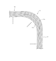
次に、巻鉄心10に巻線を組み付ける組み付け工程について説明する。この巻線の組み付け工程では、まず、図7Aに例示する巻鉄心10が、図7Bに例示するように、各鉄心材10aの切断部、換言すれば接合部14を境界として一旦開かれる。そして、図7Cに例示するように、長辺部13aに巻線600が組み付けられる。そして、図7Dに例示するように、再び、各鉄心材10aの切断部が接合するように巻鉄心10を閉じる。これにより、長辺部13aに巻線600が組み付けられた巻鉄心10が製造される。
Next, the assembly process for assembling the windings on the wound core 10 will be described. In this winding assembly process, first, the wound core 10 illustrated in FIG. 7A is once opened with the cut portion of each core material 10a, in other words, the joint portion 14 as a boundary, as illustrated in FIG. 7B. Then, as illustrated in FIG. 7C, the winding 600 is assembled to the long side portion 13a. Then, as illustrated in FIG. 7D, the wound core 10 is closed again so that the cut portions of the respective iron core members 10a are joined. Thereby, the wound core 10 in which the winding 600 is assembled to the long side portion 13a is manufactured.
このとき、巻鉄心10を開く前においては、上述した通り、各鉄心材10aの接合部14にはギャップが発生していない。よって、巻鉄心10を一旦開いたとしても、再び閉じて開く前の元通りの形状に戻すことで、接合部14にギャップが発生していない巻鉄心10を巻線600が組み付けられた状態で再生することができる。そのため、巻鉄心10を閉じる際に、接合部14のギャップを縮めるための作業、つまり、巻鉄心10の周囲を締付バンドで締め付けるといった従来の作業を行う必要がなくなり、製造工数の削減を図ることができる。
At this time, before opening the wound iron core 10, as described above, no gap is generated in the joint portion 14 of each iron core material 10a. Therefore, even if the wound core 10 is once opened, it is returned to its original shape before being closed and opened again, so that the wound core 10 in which no gap is generated at the joint 14 is assembled in the state where the winding 600 is assembled. Can be played. Therefore, when closing the wound core 10, it is not necessary to perform the work for reducing the gap of the joint portion 14, that is, the conventional work of tightening the periphery of the wound core 10 with the fastening band, thereby reducing the number of manufacturing steps. be able to.
本実施形態によれば、巻鉄心10は、コーナ部における鉄心材の占積率がコーナ部を除く辺部における鉄心材の占積率よりも低くなっている。従って、例えば巻鉄心10の成形時や締め付け時において鉄心材10aに変形が生じたとしても、その変形をコーナ部で吸収することができ、接合部14が開いてしまうことを防止することができる。よって、各製造工程において精密な寸法管理を行わなくとも、接合部14が閉じられた良好な巻鉄心10を製造することができる。また、例えば巻線の組み付け後における巻鉄心の締付工程を不要とすることができ、製造工数の増大を招くことなく巻鉄心10を製造することができる。また、製造される巻鉄心10において接合部14が開いてしまうことを防止できることから、鉄損の増大を抑制することができる。
According to the present embodiment, in the wound iron core 10, the space factor of the iron core material in the corner portion is lower than the space factor of the iron core material in the side portion excluding the corner portion. Therefore, for example, even when the core material 10a is deformed when the wound core 10 is formed or tightened, the deformation can be absorbed by the corner portion, and the joint portion 14 can be prevented from opening. . Therefore, it is possible to manufacture the favorable wound core 10 in which the joint portion 14 is closed without performing precise dimensional management in each manufacturing process. Further, for example, the winding core tightening step after the winding is assembled can be omitted, and the wound core 10 can be manufactured without increasing the number of manufacturing steps. Moreover, since it can prevent that the junction part 14 opens in the wound core 10 manufactured, the increase in a core loss can be suppressed.
また、本実施形態によれば、巻鉄心10は、所定枚の鉄心材10aごとに鉄心材群15a,15b,・・・を形成している。そして、巻鉄心10において、各鉄心材群15a,15b,・・・に含まれる鉄心材10aは、切断部が接合される接合部14が相互に周方向にずれて階段状に位置するように巻回されている。また、巻鉄心10において、一の鉄心材群において最も内側で巻回される鉄心材10aの接合部14の位置は、当該鉄心材群の内側に隣接する鉄心材群において最も内側で巻回される鉄心材10aの接合部14の位置と完全にあるいはほぼ一致している。即ち、巻鉄心10において、接合部14が形成される部分が周方向に階段状にずれるように構成した。これにより、磁路の磁気抵抗が比較的大きくなる接合部14を周方向に沿って順次ずらすことができ、巻鉄心10における磁束の流れをスムーズにすることができる。
Further, according to the present embodiment, the wound core 10 forms iron core groups 15a, 15b,... For each predetermined number of cores 10a. And, in the wound iron core 10, the iron core material 10a included in each of the iron core material groups 15a, 15b,... It is wound. Further, in the wound core 10, the position of the joint portion 14 of the iron core material 10 a wound at the innermost side in one iron core material group is wound at the innermost side in the iron core material group adjacent to the inner side of the iron core material group. The position of the joint portion 14 of the iron core material 10a is completely or substantially coincident. In other words, in the wound core 10, the portion where the joint portion 14 is formed is configured to be displaced stepwise in the circumferential direction. Thereby, the joint part 14 in which the magnetic resistance of the magnetic path is relatively large can be sequentially shifted along the circumferential direction, and the flow of magnetic flux in the wound core 10 can be made smooth.
また、本実施形態によれば、巻鉄心10は、一の鉄心材群において最も内側で巻回される鉄心材10aの周長が、当該鉄心材群の内側に隣接する鉄心材群において最も外側で巻回される鉄心材10aの周長よりも大きくなるように構成した。これにより、コーナ部12の占積率を確実に低くすることができる。また、各鉄心材10aの周長を適宜調整することにより、コーナ部12の占積率を定量的に低くすることができる。
Further, according to the present embodiment, the wound core 10 has the outermost circumference of the iron core material group adjacent to the inner side of the iron core material group in which the circumference of the iron core material 10a wound on the innermost side in one iron core material group is the outermost. It was comprised so that it might become larger than the perimeter of the iron core material 10a wound by. Thereby, the space factor of the corner part 12 can be made low reliably. Moreover, the space factor of the corner part 12 can be made quantitatively low by adjusting the circumference of each iron core material 10a suitably.
また、本実施形態に係る巻鉄心の製造方法によれば、一巻ごとに1箇所の切断部を有する複数枚の鉄心材10aを少なくとも従来よりも緩く巻回し、各鉄心材10aの切断部を接合した状態で中心に矩形の窓部11を形成する。この製造方法によれば、コーナ部12における鉄心材10aの占積率がコーナ部12を除く辺部13における鉄心材10aの占積率よりも低くなっている巻鉄心10を安定的に製造することができる。
Moreover, according to the manufacturing method of the wound core which concerns on this embodiment, the several core material 10a which has one cutting part for every volume is wound more loosely than the past, and the cutting part of each iron core material 10a is wound. A rectangular window 11 is formed at the center in the joined state. According to this manufacturing method, the wound core 10 in which the space factor of the iron core material 10 a in the corner portion 12 is lower than the space factor of the iron core material 10 a in the side portion 13 excluding the corner portion 12 is stably manufactured. be able to.
(第2実施形態)
例えば図8に示す巻鉄心20は、図示しない珪素鋼板を切断することにより得られた複数枚の鉄心材20aが巻回された構成である。この巻鉄心20は、中心にほぼ矩形の窓部21を有する。また、巻鉄心20は、窓部21の4隅に設けられる4つのコーナ部22と、これらコーナ部22を除く4つの辺部23を有する。辺部23は、コーナ部22間を繋ぐ。この場合、辺部23は、図示しない巻線が組み付けられる長辺部23aと、この長辺部23aよりも短い短辺部23bからなる。巻鉄心20を構成する鉄心材20aは、一巻き分、つまりワンターン分ごとに珪素鋼板から切断されたものであり、従って、この場合、一巻ごとに1箇所の切断部を有している。そして、各鉄心材20aにおいて切断部が接合される部分、つまり、各鉄心材20aの両端部には接合部24が形成される。
(Second Embodiment)
For example, the wound iron core 20 shown in FIG. 8 has a configuration in which a plurality of iron core members 20a obtained by cutting a silicon steel plate (not shown) are wound. The wound iron core 20 has a substantially rectangular window 21 at the center. The wound iron core 20 has four corner portions 22 provided at the four corners of the window portion 21 and four side portions 23 excluding these corner portions 22. The side portion 23 connects the corner portions 22. In this case, the side portion 23 includes a long side portion 23a to which a winding (not shown) is assembled, and a short side portion 23b shorter than the long side portion 23a. The iron core material 20a constituting the wound iron core 20 is cut from the silicon steel plate for one turn, that is, one turn, and in this case, has one cut portion for each turn. And the junction part 24 is formed in the part to which a cutting part is joined in each iron core material 20a, ie, the both ends of each iron core material 20a.
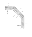
そして、例えば図9に示すように、巻鉄心20は、コーナ部22における鉄心材20aの占積率が辺部23における鉄心材20aの占積率よりも低くなっている。即ち、辺部23では鉄心材20aが密に積層されているが、コーナ部22では鉄心材20aが密に積層されておらず各鉄心材20a間に隙間を有する状態となっている。この場合、各鉄心材20aは、1枚毎に隙間を有している。
For example, as shown in FIG. 9, in the wound core 20, the space factor of the iron core material 20 a in the corner portion 22 is lower than the space factor of the iron core material 20 a in the side portion 23. That is, the iron core material 20a is densely laminated at the side portion 23, but the iron core material 20a is not densely laminated at the corner portion 22, and there is a gap between the iron core materials 20a. In this case, each iron core material 20a has a gap for each sheet.
より具体的に説明すると、図10に例示するように、例えば鉄心材20a2は、当該鉄心材20a2において辺部23を形成する部分の長さLa2が、当該鉄心材20a2の内側の鉄心材20a1において辺部23を形成する部分の長さLa1よりも所定量だけ長くなるように折り曲げられている。この場合、所定量は、「2×α」である。なお、所定量αの値は、目標とする巻鉄心20のコーナ部22の占積率に応じて、適宜変更して設定することができる。また、鉄心材20a2は、当該鉄心材20a2においてコーナ部22を形成する部分の長さLb2が、当該鉄心材20a2の内側の鉄心材20a1においてコーナ部22を形成する部分の長さLb1よりも所定量だけ長くなるように折り曲げられている。この場合、所定量は、「2×β」である。なお、所定量βの値は、目標とする巻鉄心20のコーナ部22の占積率に応じて、適宜変更して設定することができる。
More specifically, as illustrated in FIG. 10, for example, in the iron core material 20 a 2, the length La2 of the portion forming the side portion 23 in the iron core material 20 a 2 is the same as that in the iron core material 20 a 1 inside the iron core material 20 a 2. It is bent so as to be longer by a predetermined amount than the length La1 of the portion forming the side portion 23. In this case, the predetermined amount is “2 × α”. The value of the predetermined amount α can be appropriately changed and set according to the target space factor of the corner portion 22 of the wound core 20. Further, in the iron core material 20a2, the length Lb2 of the portion forming the corner portion 22 in the iron core material 20a2 is larger than the length Lb1 of the portion forming the corner portion 22 in the iron core material 20a1 inside the iron core material 20a2. It is bent so as to be longer by a fixed amount. In this case, the predetermined amount is “2 × β”. Note that the value of the predetermined amount β can be appropriately changed and set according to the target space factor of the corner portion 22 of the wound core 20.
また、この巻鉄心20も、所定枚の鉄心材20aごとに鉄心材群25a,25b,・・・を形成した構成である。即ち、内側から所定枚の鉄心材20aが積層されるごとに1つの鉄心材群25a,25b,・・・が形成される。また、各鉄心材群25a,25b,・・・に含まれる鉄心材20aは、切断部が接合される接合部24が相互に周方向にずれて階段状に位置するように巻回されている。また、例えば鉄心材群25bにおいて最も内側で巻回される鉄心材20aの接合部24の位置Pbは、当該鉄心材群25bの内側に隣接する鉄心材群25aにおいて最も内側で巻回される鉄心材群25aの接合部24の位置Paとほぼあるいは完全に一致している。また、鉄心材群25bにおいて最も内側で巻回される鉄心材20aの周長Lbは、当該鉄心材群25bの内側に隣接する鉄心材群25aにおいて最も外側で巻回される鉄心材20aの周長Laよりも大きくなっている。
Further, the wound core 20 is also configured by forming core groups 25a, 25b,... For each predetermined number of cores 20a. That is, each time a predetermined number of core members 20a are stacked from the inside, one core member group 25a, 25b,... Is formed. Moreover, the iron core material 20a included in each iron core material group 25a, 25b,... Is wound so that the joint portions 24 to which the cut portions are joined are shifted in the circumferential direction and positioned in a stepped manner. . Further, for example, the position Pb of the joint portion 24 of the iron core material 20a wound on the innermost side in the iron core material group 25b is the iron core wound on the innermost side in the iron core material group 25a adjacent to the inner side of the iron core material group 25b. It almost or completely coincides with the position Pa of the joint portion 24 of the material group 25a. Further, the circumferential length Lb of the iron core material 20a wound on the innermost side in the iron core material group 25b is the circumference of the iron core material 20a wound on the outermost side in the iron core material group 25a adjacent to the inner side of the iron core material group 25b. It is larger than the length La.
次に、このようにコーナ部22の占積率が低くなった巻鉄心20を製造するための製造方法の一例について説明する。この製造方法は、珪素鋼板の折り曲げ工程、珪素鋼板の切断工程、鉄心材の積層工程、巻鉄心の成形工程、巻鉄心の焼鈍工程からなる。
Next, an example of a manufacturing method for manufacturing the wound core 20 in which the space factor of the corner portion 22 is lowered will be described. This manufacturing method includes a bending process of a silicon steel sheet, a cutting process of the silicon steel sheet, a lamination process of a core material, a forming process of a wound core, and an annealing process of the wound core.
≪珪素鋼板の切断工程≫
この工程では、図示しない製造装置は、珪素鋼帯をフィーダによって順次送る構成である。そして、順次送られる珪素鋼帯から、一巻き分、つまりワンターン分の鉄心材20aを切断刃により順次切断する。
≪Silicon steel sheet cutting process≫
In this process, a manufacturing apparatus (not shown) is configured to sequentially feed silicon steel strips with a feeder. Then, one turn, that is, one turn of the iron core material 20a is sequentially cut by a cutting blade from the silicon steel strips that are sequentially fed.
≪珪素鋼板の折り曲げ工程≫
この工程では、図示しない製造装置は、順次送られる鉄心材20aを折り曲げ機によって適宜折り曲げる。このときの折り曲げ位置を適宜調整して設定することにより、例えば図10に示したように、適宜の位置にて折り曲げられた鉄心材20aが順次得られる。なお、珪素鋼帯を所定位置にて順次折り曲げる折り曲げ工程を行った後に、その珪素鋼帯をワンターン分ごとに切断する切断工程を行うように構成してもよい。
≪Silicon steel sheet bending process≫
In this step, a manufacturing apparatus (not shown) appropriately folds the core material 20a that is sequentially fed by a folding machine. By appropriately adjusting and setting the bending position at this time, for example, as shown in FIG. 10, the iron core material 20a bent at an appropriate position is sequentially obtained. In addition, after performing the bending process which bends a silicon steel strip sequentially in a predetermined position, you may comprise so that the cutting process which cut | disconnects the silicon steel strip for every one turn may be performed.
≪鉄心材の積層工程≫
この工程では、珪素鋼帯から得られた折り曲げ済みの鉄心材20aを順次積層する。このとき、例えば図9に示したように、コーナ部22となる部分における各鉄心材20a間には隙間が形成された状態となる。なお、この積層工程においては、各鉄心材20aを密に積層する必要はなく、折り曲げられた部分、さらには折り曲げられていない部分も含めて全体的に緩く積層すればよい。
≪Steel core lamination process≫
In this step, the folded iron core material 20a obtained from the silicon steel strip is sequentially laminated. At this time, as shown in FIG. 9, for example, a gap is formed between the iron core members 20 a in the portion that becomes the corner portion 22. In this laminating step, the iron core members 20a do not need to be densely laminated, but may be loosely laminated as a whole, including the folded portion and the unfolded portion.
≪巻鉄心の成形工程≫
この工程では、例えば図11に示すように、積層された複数枚の鉄心材20aの内側の4箇所と外側の4箇所に成形型104,105を当てる。そして、成形型104,105により、鉄心材20aの4箇所を積層方向に沿って適宜プレスする。なお、プレスは、各鉄心材20aの切断部を接合した状態で行われる。鉄心材20aの4箇所が適宜プレスされることにより、プレスされる部分に辺部23が形成され、それ以外の部分、つまり、プレスされない部分にコーナ部22が形成される。このとき、コーナ部22となる部分における各鉄心材20a間には隙間が形成されていることから、当該部分により、プレスに伴う鉄心材20aの変形を吸収することができる。よって、プレス後に、各鉄心材20aの切断部、換言すれば接合部24が開いてしまうことを防止することができる。なお、接合部24は、短辺部23bに位置して形成されるように設定されている。即ち、各鉄心材20aは、接合部24を形成する部分が短辺成形型104b,105bの間に挟まれた状態でプレスされる。
<< Molding process of wound core >>
In this step, for example, as shown in FIG. 11, the molds 104 and 105 are applied to the four inner portions and the four outer portions of the plurality of stacked iron core members 20 a. And the four places of the iron core material 20a are suitably pressed along the lamination direction by the molds 104 and 105. In addition, a press is performed in the state which joined the cutting part of each iron core material 20a. By appropriately pressing the four places of the iron core material 20a, the side portion 23 is formed in the pressed portion, and the corner portion 22 is formed in the other portion, that is, the portion that is not pressed. At this time, since gaps are formed between the iron core members 20a in the portions to be the corner portions 22, the portions can absorb the deformation of the iron core materials 20a accompanying the press. Therefore, it can prevent that the cutting part of each iron core material 20a, ie, the junction part 24, opens after pressing. In addition, the junction part 24 is set so that it may be located in the short side part 23b. That is, each iron core material 20a is pressed in a state in which a portion forming the joint portion 24 is sandwiched between the short- side molds 104b and 105b.
≪巻鉄心の焼鈍工程≫
この工程では、巻鉄心20を、例えば約800℃ほどの所定温度に加熱した後に冷却する。これにより、巻鉄心20を構成する各鉄心材20aに生じている残留応力を緩和することができ、残留応力に起因して巻鉄心20の鉄損特性が悪化してしまうことを回避することができる。なお、残留応力が解消されることに伴い各鉄心材20aが若干変形する場合がある。しかし、このような変形が生じたとしても、その変形は、占積率が低いコーナ部22が適宜変形することにより吸収される。よって、この焼鈍工程により接合部24が開いてしまうことも防止される。
≪Annealing process of wound iron core≫
In this step, the wound core 20 is cooled after being heated to a predetermined temperature of about 800 ° C., for example. Thereby, the residual stress which has arisen in each iron core material 20a which constitutes wound iron core 20 can be relieved, and it can avoid that the iron loss characteristic of wound iron core 20 is deteriorated due to the residual stress. it can. Note that each core material 20a may be slightly deformed as the residual stress is eliminated. However, even if such deformation occurs, the deformation is absorbed by appropriately deforming the corner portion 22 having a low space factor. Therefore, it is possible to prevent the joint portion 24 from being opened by this annealing process.
以上の各工程により、コーナ部22における鉄心材20aの占積率が辺部23における鉄心材20aの占積率よりも低くなっている巻鉄心20が製造される。この巻鉄心20において、各鉄心材20aが形成する接合部24は殆どあるいは全く開いておらず、接合部24においてギャップは殆どあるいは全く発生していない。
Through the above steps, the wound core 20 in which the space factor of the iron core material 20a in the corner portion 22 is lower than the space factor of the iron core material 20a in the side portion 23 is manufactured. In the wound core 20, the joint portions 24 formed by the respective core members 20 a are hardly or not open, and the gap is not generated at all in the joint portions 24.
次に、巻鉄心20に巻線を組み付ける組み付け工程について説明する。図示は省略するが、この巻線の組み付け工程では、まず、巻鉄心20が、各鉄心材20aの切断部、換言すれば接合部24を境界として一旦開かれる。そして、長辺部23aに巻線が組み付けられる。そして、再び、各鉄心材20aの切断部が接合するように巻鉄心20を閉じる。巻鉄心20を開く前においては、上述した通り、各鉄心材20aの接合部24にはギャップが発生していない。よって、巻鉄心20を一旦開いたとしても、再び閉じて開く前の元通りの形状に戻すことで、接合部24にギャップが発生していない巻鉄心20を巻線が組み付けられた状態で再生することができる。そのため、巻鉄心20を閉じる際に、接合部24のギャップを縮めるための作業を行う必要がなくなり、製造工数の削減を図ることができる。
Next, the assembly process for assembling the windings on the wound core 20 will be described. Although illustration is omitted, in this winding assembling step, first, the wound core 20 is once opened with the cut portion of each core member 20a, in other words, the joint 24 as a boundary. And the coil | winding is assembled | attached to the long side part 23a. And the wound core 20 is closed again so that the cutting part of each iron core material 20a may join. Before opening the wound core 20, as described above, no gap is generated in the joint portion 24 of each core material 20 a. Therefore, even if the wound core 20 is once opened, the wound core 20 in which no gap is generated at the joint 24 is regenerated in a state where the windings are assembled by returning to the original shape before closing and opening again. can do. Therefore, when closing the wound iron core 20, it is not necessary to perform an operation for reducing the gap of the joint portion 24, and the number of manufacturing steps can be reduced.
本実施形態によれば、巻鉄心20は、コーナ部における鉄心材の占積率がコーナ部を除く辺部における鉄心材の占積率よりも低くなっている。従って、例えば巻鉄心20の成形時や締め付け時において鉄心材20aに変形が生じたとしても、その変形をコーナ部で吸収することができ、接合部24が開いてしまうことを防止することができる。よって、各製造工程において精密な寸法管理を行わなくとも、接合部24が閉じられた良好な巻鉄心20を製造することができる。また、例えば巻線の組み付け後における巻鉄心の締付工程を不要とすることができ、製造工数の増大を招くことなく巻鉄心20を製造することができる。また、製造される巻鉄心20において接合部24が開いてしまうことを防止できることから、鉄損の増大を抑制することができる。
According to the present embodiment, in the wound iron core 20, the space factor of the iron core material in the corner portion is lower than the space factor of the iron core material in the side portion excluding the corner portion. Therefore, for example, even when the core material 20a is deformed when the wound core 20 is molded or tightened, the deformation can be absorbed by the corner portion, and the joint portion 24 can be prevented from opening. . Therefore, it is possible to manufacture the favorable wound core 20 in which the joint portion 24 is closed without performing precise dimensional management in each manufacturing process. Further, for example, a winding core tightening step after the winding is assembled can be omitted, and the wound core 20 can be manufactured without increasing the number of manufacturing steps. Moreover, since it can prevent that the junction part 24 opens in the wound core 20 manufactured, the increase in a core loss can be suppressed.
また、本実施形態によれば、巻鉄心20は、所定枚の鉄心材20aごとに鉄心材群25a,25b,・・・を形成している。そして、巻鉄心20において、各鉄心材群25a,25b,・・・に含まれる鉄心材20aは、切断部が接合される接合部24が相互に周方向にずれて階段状に位置するように巻回されている。また、巻鉄心20において、一の鉄心材群において最も内側で巻回される鉄心材20aの接合部24の位置は、当該鉄心材群の内側に隣接する鉄心材群において最も内側で巻回される鉄心材20aの接合部24の位置と完全にあるいはほぼ一致している。即ち、巻鉄心20において、接合部24が形成される部分が周方向に階段状にずれるように構成した。これにより、磁路の磁気抵抗が比較的大きくなる接合部24を周方向に沿って順次ずらすことができ、巻鉄心10における磁束の流れをスムーズにすることができる。
Further, according to the present embodiment, the wound core 20 forms the core group 25a, 25b,... For each predetermined number of cores 20a. In the wound core 20, the core material 20 a included in each of the core material groups 25 a, 25 b,... Is positioned so that the joints 24 to which the cut parts are joined are shifted in the circumferential direction and are stepped. It is wound. In addition, in the wound core 20, the position of the joint portion 24 of the iron core material 20 a wound on the innermost side in one iron core material group is wound on the innermost side in the iron core material group adjacent to the inner side of the iron core material group. The position of the joint 24 of the iron core material 20a is completely or substantially coincident. In other words, the wound core 20 is configured such that the portion where the joint 24 is formed is shifted stepwise in the circumferential direction. Thereby, the joint part 24 in which the magnetic resistance of the magnetic path is relatively large can be sequentially shifted along the circumferential direction, and the flow of magnetic flux in the wound core 10 can be made smooth.
また、本実施形態によれば、巻鉄心20は、一の鉄心材群において最も内側で巻回される鉄心材20aの周長が、当該鉄心材群の内側に隣接する鉄心材群において最も外側で巻回される鉄心材20aの周長よりも大きくなるように構成した。これにより、コーナ部22の占積率を確実に低くすることができる。また、各鉄心材20aの周長を適宜調整することにより、コーナ部22の占積率を定量的に低くすることができる。
In addition, according to the present embodiment, the wound core 20 has the outer circumference of the iron core material group adjacent to the inner side of the iron core material group in which the circumference of the iron core material 20a wound at the innermost side in one iron core material group is the outermost. It was comprised so that it might become larger than the perimeter of the iron core material 20a wound by. Thereby, the space factor of the corner part 22 can be made low reliably. Moreover, the space factor of the corner part 22 can be quantitatively lowered by appropriately adjusting the circumference of each iron core material 20a.
また、本実施形態に係る巻鉄心の製造方法によれば、一巻ごとに1箇所の切断部を有し、且つ、コーナ部22を形成する部分が予め折り曲げられた鉄心材20aを緩く積層し、各鉄心材20aの切断部を接合した状態で中心に矩形の窓部21を形成する。この製造方法においては、鉄心材20aを積層する前に、一の鉄心材において辺部を形成する部分の長さを、当該鉄心材の内側の鉄心材において辺部を形成する部分の長さよりも所定量長くなるように折り曲げ、且つ、一の鉄心材においてコーナ部を形成する部分の長さを、当該鉄心材の内側の鉄心材においてコーナ部を形成する部分の長さよりも所定量長くなるように折り曲げる。この製造方法によっても、コーナ部22における鉄心材20aの占積率がコーナ部22を除く辺部13における鉄心材20aの占積率よりも低くなっている巻鉄心20を安定的に製造することができる。
In addition, according to the method for manufacturing a wound core according to the present embodiment, the core material 20a that has one cut portion for each turn and in which a portion that forms the corner portion 22 is folded in advance is loosely laminated. The rectangular window portion 21 is formed at the center in a state where the cut portions of the iron core members 20a are joined. In this manufacturing method, before laminating the iron core material 20a, the length of the portion forming the side portion in one iron core material is set longer than the length of the portion forming the side portion in the iron core material inside the iron core material. Folded to be a predetermined amount longer, and the length of the portion forming the corner portion in one iron core material is longer than the length of the portion forming the corner portion in the iron core material inside the iron core material by a predetermined amount. Bend it. Also by this manufacturing method, the wound core 20 in which the space factor of the iron core material 20a in the corner portion 22 is lower than the space factor of the iron core material 20a in the side portion 13 excluding the corner portion 22 is stably manufactured. Can do.
以上に説明した実施形態に係る巻鉄心は、一巻ごとに少なくとも1箇所の切断部を有する複数枚の鉄心材が巻回され、中心に矩形の窓部を有する巻鉄心であって、コーナ部における前記鉄心材の占積率が前記コーナ部を除く辺部における前記鉄心材の占積率よりも低くなっている。
The wound iron core according to the embodiment described above is a wound iron core in which a plurality of iron core materials each having at least one cut portion are wound for each turn and having a rectangular window portion at the center, and a corner portion. The space factor of the iron core material is lower than the space factor of the iron core material in the side portion excluding the corner portion.
また、以上に説明した実施形態に係る巻鉄心の製造方法は、一巻ごとに少なくとも1箇所の切断部を有する複数枚の鉄心材を緩く巻回し、各鉄心材の前記切断部を接合した状態で中心に矩形の窓部を形成することにより、コーナ部における前記鉄心材の占積率が前記コーナ部を除く辺部における前記鉄心材の占積率よりも低くなっている巻鉄心を製造する。
Moreover, the manufacturing method of the wound core which concerns on embodiment described above is the state which wound the several core material which has a cutting part of at least 1 place for every volume loosely, and joined the said cutting part of each iron core material By forming a rectangular window at the center, a wound core in which the space factor of the iron core material in the corner portion is lower than the space factor of the iron core material in the side portion excluding the corner portion is manufactured. .
また、以上に説明した実施形態に係る巻鉄心の製造方法は、一巻ごとに少なくとも1箇所の切断部を有し、且つ、コーナ部を形成する部分が予め折り曲げられた鉄心材を緩く積層し、各鉄心材の前記切断部を接合した状態で中心に矩形の窓部を形成することにより、前記コーナ部における前記鉄心材の占積率が前記コーナ部を除く辺部における前記鉄心材の占積率よりも低くなっている巻鉄心を製造する製造方法であって、前記鉄心材を積層する前に、一の前記鉄心材において前記辺部を形成する部分の長さを、当該鉄心材の内側の鉄心材において前記辺部を形成する部分の長さよりも所定量長くなるように折り曲げ、且つ、一の前記鉄心材において前記コーナ部を形成する部分の長さを、当該鉄心材の内側の鉄心材において前記コーナ部を形成する部分の長さよりも所定量長くなるように折り曲げる。
In addition, the method for manufacturing a wound core according to the above-described embodiment includes loosely laminating an iron core material that has at least one cut portion for each turn, and a portion that forms a corner portion is bent in advance. By forming a rectangular window at the center in a state where the cut portions of each iron core member are joined, the space factor of the iron core material in the corner portion is such that the iron core material is occupied in the side portions other than the corner portion. In the manufacturing method for manufacturing a wound core that is lower than the volume ratio, before laminating the iron core material, the length of the portion forming the side portion in the iron core material is determined by the length of the iron core material. The inner core material is bent so as to be a predetermined amount longer than the length of the portion that forms the side portion, and the length of the portion that forms the corner portion of the one iron core material is set to the inside of the core material. In the core material, the corner The length of the forming part bent so that a predetermined amount longer than.
以上に説明した実施形態によれば、製造工程における精密な寸法管理を要することなく、また、製造工数の増大を招くことなく製造することができ、且つ、鉄損の増大を抑制することができる。
According to the embodiment described above, it is possible to manufacture without requiring precise dimensional control in the manufacturing process, without increasing the number of manufacturing steps, and to suppress an increase in iron loss. .
なお、本実施形態は、例として提示したものであり、発明の範囲を限定することは意図していない。これら新規な実施形態は、その他の様々な形態で実施されることが可能であり、発明の要旨を逸脱しない範囲で、種々の省略、置き換え、変更を行うことができる。本実施形態およびその変形は、発明の範囲および要旨に含まれるとともに、請求の範囲に記載された発明とその均等の範囲に含まれる。
Note that this embodiment is presented as an example and is not intended to limit the scope of the invention. These novel embodiments can be implemented in various other forms, and various omissions, replacements, and changes can be made without departing from the scope of the invention. This embodiment and its modifications are included in the scope and gist of the invention, and are included in the invention described in the claims and the equivalents thereof.
例えば、鉄心材は、一巻ごとに1箇所の切断部を有するものに限られず、一巻ごとに複数箇所の切断部を有するものであってもよい。即ち、鉄心材は、一巻ごとに少なくとも1箇所の切断部を有するものであれば、本実施形態に係る技術思想に含まれる。
For example, the iron core material is not limited to one having one cut portion per turn, and may have a plurality of cut portions per turn. That is, the iron core material is included in the technical idea according to the present embodiment as long as it has at least one cut portion for each roll.
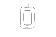
また、例えば図12に示すように、巻鉄心10は、コーナ部12における各鉄心材10aが複数枚毎に隙間を有している構成としてもよい。また、例えば図13に示すように、巻鉄心20は、コーナ部22における各鉄心材20aが複数枚毎に隙間を有している構成としてもよい。この場合、隙間と隙間との間に存在させる鉄心材10aあるいは鉄心材20aの枚数は適宜変更して実施することができ、例えば、上述した鉄心材群毎に隙間を有する構成とすることができる。また、図示はしないが、巻鉄心は、コーナ部において、各鉄心材が1枚毎に隙間を有する領域と各鉄心材が複数枚毎に隙間を有する領域とを混在させる構成としてもよい。
For example, as shown in FIG. 12, the wound core 10 may have a configuration in which each of the core members 10 a in the corner portion 12 has a gap for each of a plurality of sheets. Further, for example, as shown in FIG. 13, the wound core 20 may have a configuration in which each of the core members 20 a in the corner portion 22 has a gap for every plurality. In this case, the number of the iron core material 10a or the iron core material 20a existing between the gaps can be changed as appropriate. For example, the above-described iron core material group can have a gap. . Although not shown, the wound core may have a configuration in which a region in which each iron core material has a gap for each sheet and a region in which each iron core material has a gap for every plurality of sheets are mixed in the corner portion.