WO2015107965A1 - Aluminum porous body, electrode for electricity storage devices, and electricity storage device - Google Patents
Aluminum porous body, electrode for electricity storage devices, and electricity storage device Download PDFInfo
- Publication number
- WO2015107965A1 WO2015107965A1 PCT/JP2015/050308 JP2015050308W WO2015107965A1 WO 2015107965 A1 WO2015107965 A1 WO 2015107965A1 JP 2015050308 W JP2015050308 W JP 2015050308W WO 2015107965 A1 WO2015107965 A1 WO 2015107965A1
- Authority
- WO
- WIPO (PCT)
- Prior art keywords
- electrode
- aluminum
- active material
- porous body
- electrode active
- Prior art date
Links
Images

Classifications
-
- H—ELECTRICITY
- H01—ELECTRIC ELEMENTS
- H01M—PROCESSES OR MEANS, e.g. BATTERIES, FOR THE DIRECT CONVERSION OF CHEMICAL ENERGY INTO ELECTRICAL ENERGY
- H01M4/00—Electrodes
- H01M4/02—Electrodes composed of, or comprising, active material
- H01M4/64—Carriers or collectors
- H01M4/70—Carriers or collectors characterised by shape or form
- H01M4/80—Porous plates, e.g. sintered carriers
- H01M4/806—Nonwoven fibrous fabric containing only fibres
-
- H—ELECTRICITY
- H01—ELECTRIC ELEMENTS
- H01G—CAPACITORS; CAPACITORS, RECTIFIERS, DETECTORS, SWITCHING DEVICES OR LIGHT-SENSITIVE DEVICES, OF THE ELECTROLYTIC TYPE
- H01G11/00—Hybrid capacitors, i.e. capacitors having different positive and negative electrodes; Electric double-layer [EDL] capacitors; Processes for the manufacture thereof or of parts thereof
- H01G11/04—Hybrid capacitors
- H01G11/06—Hybrid capacitors with one of the electrodes allowing ions to be reversibly doped thereinto, e.g. lithium ion capacitors [LIC]
-
- H—ELECTRICITY
- H01—ELECTRIC ELEMENTS
- H01G—CAPACITORS; CAPACITORS, RECTIFIERS, DETECTORS, SWITCHING DEVICES OR LIGHT-SENSITIVE DEVICES, OF THE ELECTROLYTIC TYPE
- H01G11/00—Hybrid capacitors, i.e. capacitors having different positive and negative electrodes; Electric double-layer [EDL] capacitors; Processes for the manufacture thereof or of parts thereof
- H01G11/22—Electrodes
- H01G11/24—Electrodes characterised by structural features of the materials making up or comprised in the electrodes, e.g. form, surface area or porosity; characterised by the structural features of powders or particles used therefor
-
- H—ELECTRICITY
- H01—ELECTRIC ELEMENTS
- H01G—CAPACITORS; CAPACITORS, RECTIFIERS, DETECTORS, SWITCHING DEVICES OR LIGHT-SENSITIVE DEVICES, OF THE ELECTROLYTIC TYPE
- H01G11/00—Hybrid capacitors, i.e. capacitors having different positive and negative electrodes; Electric double-layer [EDL] capacitors; Processes for the manufacture thereof or of parts thereof
- H01G11/22—Electrodes
- H01G11/30—Electrodes characterised by their material
- H01G11/50—Electrodes characterised by their material specially adapted for lithium-ion capacitors, e.g. for lithium-doping or for intercalation
-
- H—ELECTRICITY
- H01—ELECTRIC ELEMENTS
- H01M—PROCESSES OR MEANS, e.g. BATTERIES, FOR THE DIRECT CONVERSION OF CHEMICAL ENERGY INTO ELECTRICAL ENERGY
- H01M4/00—Electrodes
- H01M4/02—Electrodes composed of, or comprising, active material
- H01M4/64—Carriers or collectors
- H01M4/66—Selection of materials
- H01M4/661—Metal or alloys, e.g. alloy coatings
-
- Y—GENERAL TAGGING OF NEW TECHNOLOGICAL DEVELOPMENTS; GENERAL TAGGING OF CROSS-SECTIONAL TECHNOLOGIES SPANNING OVER SEVERAL SECTIONS OF THE IPC; TECHNICAL SUBJECTS COVERED BY FORMER USPC CROSS-REFERENCE ART COLLECTIONS [XRACs] AND DIGESTS
- Y02—TECHNOLOGIES OR APPLICATIONS FOR MITIGATION OR ADAPTATION AGAINST CLIMATE CHANGE
- Y02E—REDUCTION OF GREENHOUSE GAS [GHG] EMISSIONS, RELATED TO ENERGY GENERATION, TRANSMISSION OR DISTRIBUTION
- Y02E60/00—Enabling technologies; Technologies with a potential or indirect contribution to GHG emissions mitigation
- Y02E60/10—Energy storage using batteries
Definitions
- the present invention relates to an aluminum porous body, an electrode for an electricity storage device obtained using the aluminum porous body, and an electricity storage device.
- Metal porous bodies are used in various fields such as filters, catalyst carriers, and current collectors for electricity storage devices.
- Examples of the metal porous body include those having a three-dimensional network structure in addition to those having a two-dimensional structure such as a punching metal sheet or a metal mesh.
- Patent Document 1 proposes an aluminum porous material having a three-dimensional network structure.
- Patent Document 2 proposes to use a porous metal body having a foam shape and containing aluminum and titanium as a positive electrode current collector of a lithium ion secondary battery.
- a positive electrode for a lithium ion secondary battery is produced by filling a porous metal body containing aluminum with a positive electrode active material, drying, and compression molding.
- the three-dimensional network structure is bulky and the porosity is high.
- an electrode mixture or a catalyst composition is placed inside the network structure. A large amount can be filled.
- the metal porous body has a high porosity, the mass ratio of the metal contained in the metal porous body is small. Therefore, in the metal porous body having a three-dimensional network structure, the conductivity is likely to be lowered, which may cause a problem in applications where high conductivity is required.
- An object of the present invention is to provide an aluminum porous body having high conductivity, an electrode for an electricity storage device and an electricity storage device obtained using the aluminum porous body.
- One aspect of the present invention is an aluminum porous body having a three-dimensional network skeleton in which a plurality of fiber parts including aluminum or an aluminum alloy are three-dimensionally connected, and the mass per unit volume is 30 to 1100 mg / Cm 3 , the number F t of the fiber portions per unit length in the thickness direction in the cross section in the thickness direction of the aluminum porous body, and the unit length in the surface direction on the surface of the aluminum porous body
- the ratio F t / F p to the number F p of fiber parts relates to a porous aluminum body having a ratio of 1.4 or more.
- Another aspect of the present invention is formed by filling the aluminum porous body as an electrode current collector with an electrode mixture containing a first electrode active material and compressing the aluminum porous body in the thickness direction of the aluminum porous body.
- the present invention relates to an electrode for an electricity storage device.
- Still another aspect of the present invention includes a first electrode, a second electrode having a polarity opposite to that of the first electrode, a separator interposed between the first electrode and the second electrode, and an electrolyte.
- At least the first electrode is an electrode for the electricity storage device, and the second electrode relates to an electricity storage device containing a second electrode active material.
- the aluminum porous body has a low resistance, that is, a high conductivity despite having a three-dimensional network structure.
- the output of the electrode and the electricity storage device can be increased.
- FIG. 1 It is an optical microscope photograph of the section in the thickness direction of the aluminum porous body concerning one embodiment of the present invention. It is a cross-sectional schematic diagram of the aluminum porous body of FIG. 1 is a longitudinal sectional view schematically showing an electricity storage device according to an embodiment of the present invention.
- One embodiment of the present invention is (1) an aluminum porous body having a three-dimensional network skeleton in which a plurality of fiber parts including aluminum or an aluminum alloy are three-dimensionally connected, and the mass per unit volume is 30 to 1100 mg / cm 3 , the number F t of fiber portions per unit length in the thickness direction in the cross section in the thickness direction of the porous aluminum body, and the unit length in the surface direction on the surface of the porous aluminum body
- the ratio F t / F p with respect to the number F p of fiber portions per thickness relates to a porous aluminum body having a ratio of 1.4 or more.
- the conventional metal porous body having a three-dimensional network structure it is possible to reduce the weight by increasing the porosity and / or to fill a large amount of the electrode mixture or the catalyst composition. An effect is obtained.
- the porosity of the metal porous body is increased, the mass ratio of the metal contained in the metal porous body is decreased, so that the conductivity is easily lowered. Therefore, depending on the application, a decrease in conductivity may be a problem.
- the electrode is obtained by filling the metal porous body with an electrode mixture and then compressing the metal porous body in the thickness direction. It is done.
- the metal porous body is compressed after filling the electrode mixture into the metal porous body, it is difficult to increase the compression rate. If the compression ratio is low, the density of the part that forms the skeleton of the three-dimensional network structure of the metal porous body, that is, the fiber part (or rod-like part) cannot be increased, and it is difficult to be close to each other. Hateful.
- the mass (or apparent density) per unit volume is 30 to 1100 mg / cm 3 , and the ratio F t / F p is 1.4 or more. To do. With such a configuration, since the fiber parts forming the skeleton of the porous aluminum body can be brought close to each other, the conductivity can be increased.
- the aluminum porous body has a shape of a porous sheet having a predetermined thickness.
- the aluminum porous body is filled from the surface (specifically, one or both main surfaces) of the aluminum porous body.
- the surface (and the surface direction of the aluminum porous body) has a large distance between the fiber parts, and therefore it is easy to fill the electrode mixture or the catalyst composition. Accordingly, even when the apparent density of the porous aluminum body is high, the electrode mixture or the catalyst composition can be filled more uniformly.
- the three-dimensional network skeleton has a fiber part (or rod-like part) formed of aluminum or an aluminum alloy, or a skeleton in which the fiber parts are connected three-dimensionally to form a network. Refers to the structure.
- Number F t of the fiber portion in the thickness direction of the cross section of the porous aluminum, a predetermined length (e.g., 0.1 mm) when drawn a line segment having a parallel to the thickness direction, the fibrous portion intersecting the segment This means that the number is converted per unit length (for example, 1 mm).
- the number of fiber portions F p is a fiber that intersects a line segment having a predetermined length (for example, 0.1 mm) on the surface of the aluminum porous body in parallel with the surface direction of the aluminum porous body. This means that the number of parts is converted per unit length (for example, 1 mm).
- the fiber portions of the aluminum porous body are more densely distributed in the thickness direction than in the plane direction.
- the number of fiber parts can be measured using, for example, a cross section in the thickness direction of the porous aluminum body or an optical micrograph of the surface.
- the surface of the aluminum porous body refers to one main surface of the porous sheet in the aluminum porous body having the shape of the porous sheet having a predetermined thickness.
- the skeleton of the porous aluminum body is hollow.
- Such an aluminum porous body is advantageous because it is lightweight. Since the hollow skeleton of the porous aluminum body has a tunnel shape or a tube shape, when it is used for producing an electrode of an electricity storage device, the electrolyte is more easily distributed in the electricity storage device.
- the ratio F t / F p is preferably 1.4 to 10. When the ratio F t / F p is in such a range, the conductivity can be further enhanced while ensuring high filling properties.
- the number F t of the fiber unit is preferably 2 to 50 lines / mm. When Ft is in such a range, it is easy to improve conductivity while ensuring high filling properties.
- the porous aluminum body preferably has a thickness of 0.1 to 0.65 mm.
- the conductivity can be further increased.
- the aluminum porous body as an electrode current collector is filled with an electrode mixture containing a first electrode active material, and compressed in the thickness direction of the aluminum porous body. It relates to an electrode for an electricity storage device formed by the above.
- the porous aluminum body has high conductivity because the fiber parts are close to each other before filling the electrode mixture. After filling the electrode mixture, the conductivity of the obtained electrode can be further increased by further compressing the porous aluminum body. By increasing the conductivity of the electrode, the power storage device can have high output. Moreover, since the distance between fiber parts is large in the surface direction compared to the thickness direction of the aluminum porous body, it is easy to uniformly fill the electrode mixture.
- Still another embodiment of the present invention includes (7) a first electrode, a second electrode having a polarity opposite to that of the first electrode, a separator interposed between the first electrode and the second electrode, and
- the electrical storage device contains an electrolyte, at least the first electrode is the electrode described in (6) above, and the second electrode contains a second electrode active material.
- the electricity storage device is a lithium ion capacitor
- the electrolyte contains lithium ions and anions
- the first electrode active material is made of a material that reversibly carries at least the anions.
- the second electrode active material includes a material that reversibly carries the lithium ions.
- the electricity storage device is an electric double layer capacitor (EDLC)
- the electrolyte includes a cation and an anion
- the first electrode active material is at least
- the second electrode active material includes a material that reversibly supports the anion
- the second electrode active material includes a material that reversibly supports the cation.
- the power storage device is EDLC
- the electrolyte includes a cation and an anion
- the first electrode active material includes a material that reversibly supports the cation
- the second electrode active It is also preferable that the substance includes at least a material that reversibly carries the anion.
- a high-power EDLC can be obtained by using the electrode as at least the first electrode.
- the electricity storage device is a non-aqueous electrolyte secondary battery
- the electrolyte includes an alkali metal ion and an anion
- the first electrode active material is the alkali metal ion
- the second electrode active material includes a material that reversibly supports the alkali metal ions.
- the aluminum porous body contains aluminum or an aluminum alloy.
- the aluminum content in the aluminum porous body is, for example, 80% by mass or more, preferably 90% by mass or more, and more preferably 95% by mass or more or 98% by mass or more.
- the aluminum content in the aluminum porous body is 100% by mass or less, and may be 99.9% by mass or less. These lower limit values and upper limit values can be arbitrarily combined.
- the aluminum content in the aluminum porous body may be, for example, 80 to 100% by mass, or 95 to 100% by mass.
- the aluminum porous body may contain impurities inevitably mixed.
- Examples of the aluminum alloy contained in the porous aluminum body include an aluminum-iron alloy, an aluminum-copper alloy, an aluminum-manganese alloy, an aluminum-silicon alloy, an aluminum-magnesium alloy, an aluminum-magnesium-silicon alloy, an aluminum-zinc alloy, Examples include aluminum-nickel alloys.
- the aluminum porous body includes a plurality of fiber parts (or rod-like parts).
- the plurality of fiber portions are three-dimensionally connected to form a three-dimensional network skeleton.
- the three-dimensional network skeleton of the porous aluminum body has a cavity inside (that is, is hollow). Since the cavity in the skeleton of the aluminum porous body has a communication hole shape, the skeleton of the aluminum porous body has a tunnel shape or a tube shape.
- a porous aluminum body having a hollow skeleton is extremely lightweight while having a bulky three-dimensional structure.
- the apparent density of the aluminum porous body is 30 mg / cm 3 or more, preferably 50 mg / cm 3 or more, or 100 mg / cm 3 or more, more preferably 150 mg / cm 3 or more, or 175 mg / cm 3 or more.
- the apparent density of the aluminum porous body is 1100 mg / cm 3 or less, preferably 1000 mg / cm 3 or less, more preferably 700 mg / cm 3 or less. These lower limit values and upper limit values can be arbitrarily combined.
- the apparent density of the aluminum porous body may be, for example, 30 to 1100 mg / cm 3 , 50 to 1000 mg / cm 3, or 150 to 1000 mg / cm 3 .
- the porosity (or porosity) of the aluminum porous body is 50% by volume or more, preferably 55% by volume or more, and more preferably 60% by volume or more.
- the porosity is less than 100% by volume, preferably 99.5% by volume or less, more preferably 99% by volume or less. These lower limit values and upper limit values can be arbitrarily combined.
- the porosity may be, for example, 50 volume% or more and less than 100 volume%, 50 to 99 volume%, or 60 to 99 volume%.
- Ratio F t of the number F t of fiber parts per unit length in the thickness direction in the cross section in the thickness direction of the porous aluminum body and the number F p of fiber parts per unit length in the surface direction on the surface of the aluminum porous body / Fp is 1.4 or more, preferably 1.6 or more, more preferably 1.9 or more, or 2.3 or more.
- the ratio F t / F p is, for example, 10 or less, preferably 9 or less, more preferably 8 or less or 6 or less. These lower limit values and upper limit values can be arbitrarily combined.
- the ratio F t / F p may be, for example, 1.4 to 10, 1.6 to 9, or 1.9 to 8.
- the aluminum porous body according to the embodiment of the present invention has a high apparent density while having a somewhat high porosity.
- the porosity is high, the distance between the fiber portions of the aluminum porous body tends to be large, and the conductivity is likely to decrease.
- the mass ratio of aluminum or aluminum alloy in the aluminum porous body can be increased, so that the conductivity of the aluminum porous body can be increased.
- these components cannot be filled sufficiently.
- the ratio F t / F p of the number of fiber parts to the above values, even in applications such as filling an electrode mixture or a catalyst composition, A decrease in filling property can be suppressed.
- the ratio F t / F p is in the above range, when the electrode mixture is filled, the distance between the electrode active material particles contained in the electrode mixture and the fiber portion can be easily reduced. Therefore, even in such applications, the conductivity can be effectively increased, and the output of the electrode obtained using the aluminum porous body can be improved.
- the number F t of fiber parts is, for example, 2 to 50 / mm, preferably 2.5 to 45 / mm or 3 to 40 / mm, more preferably 5 to 30 / mm or 6 to 25 / mm. mm.
- the number F t of fiber parts is, for example, 2 to 50 / mm, preferably 2.5 to 45 / mm or 3 to 40 / mm, more preferably 5 to 30 / mm or 6 to 25 / mm. mm.
- the thickness of the aluminum porous body is, for example, 0.65 mm or less, preferably 0.63 mm or less, and more preferably 0.62 mm or less.
- the thickness of the aluminum porous body is, for example, 0.10 mm or more, preferably 0.13 mm or more. These lower limit values and upper limit values can be arbitrarily combined.
- the thickness of the aluminum porous body may be, for example, 0.10 to 0.65 mm or 0.13 to 0.62 mm. When the thickness of the porous aluminum body is in such a range, it is more advantageous in increasing the conductivity.
- the aluminum porous body can be formed, for example, by coating a resin porous body having continuous voids with a metal (specifically, aluminum and / or an aluminum alloy). After coating with a metal, it may be compressed in the thickness direction as necessary.
- the mass per unit volume, porosity, ratio F t / F p, etc. of the aluminum porous body can be adjusted by controlling the structure of the resin porous body and / or the degree of compression after coating. From the viewpoint of easily controlling the ratio F t / F p , it is preferable to use compression in the thickness direction.
- the coating with metal can be performed by, for example, plating, vapor phase method (evaporation, plasma chemical vapor deposition, sputtering, etc.), application of metal paste, or the like.
- a three-dimensional network skeleton is formed by coating with metal. Of these coating methods, plating is preferred.
- the plating treatment it is only necessary to form a layer of aluminum or an aluminum alloy on the surface of the resin porous body (including the surface in the continuous void), and a known plating treatment method such as an electrolytic plating method, a molten salt plating method, etc. Can be adopted. By the plating process, a three-dimensional mesh-like aluminum porous body corresponding to the shape of the resin porous body is formed.
- a conductive layer prior to electrolytic plating.
- the conductive layer may be formed on the surface of the resin porous body by electroless plating, vapor deposition, sputtering, or by applying a conductive agent.
- the resin porous body is immersed in a dispersion containing the conductive agent. May be formed.
- the resin porous body is not particularly limited as long as it has continuous voids, and a resin foam, a resin nonwoven fabric, or the like can be used.
- a resin foam, a resin nonwoven fabric, or the like As the resin constituting these porous bodies, those capable of making the inside of the skeleton hollow by decomposition or dissolution while maintaining the shape of the metal three-dimensional network skeleton after the metal coating treatment are preferable.
- the resin in the skeleton is desirably decomposed or dissolved and removed by heat treatment or the like. After the heat treatment, components (resin, decomposition product, unreacted monomer, additive contained in the resin, etc.) remaining in the skeleton may be removed by washing or the like.
- the resin may be removed by performing a heat treatment while appropriately applying a voltage as necessary.
- this heat treatment may be performed while applying a voltage in a state where the plated porous body is immersed in a molten salt plating bath.
- a cavity such as a communication hole-like cavity
- the metal porous body that is, the aluminum porous body
- thermosetting resins such as thermosetting polyurethane and melamine resin
- thermoplastic resins such as olefin resin (polyethylene, polypropylene and the like) and thermoplastic polyurethane.
- resin foam depending on the type of resin and / or the method of producing the foam, each pore formed inside the foam becomes a cellular shape, and these are connected in series, and continuous voids. Is formed.
- a current collector using a resin foam.
- thermosetting polyurethane etc. from a viewpoint that a void
- the porous metal body thus obtained has a three-dimensional network structure skeleton corresponding to the shape of the resin foam.
- each porous aluminum body has a large number of cell-like pores, and has continuous voids (that is, communication holes) in which these cell-like pores communicate with each other.
- an opening (or window) is formed between the adjacent cell-shaped holes and the openings are in communication with each other.
- the shape of the opening (or window) is not particularly limited, and is, for example, a substantially polygonal shape (such as a substantially triangular shape, a substantially square shape, a substantially pentagonal shape, and / or a substantially hexagonal shape).
- the substantially polygonal shape is used in the meaning including a polygon and a shape similar to the polygon (for example, a shape in which the corners of the polygon are rounded or a shape in which the sides of the polygon are curved).
- the metal porous body can be compressed in the thickness direction after the metal coating process or after the metal coating process is performed to remove the internal resin.
- the degree of compression can be adjusted so that the apparent density, porosity, and ratio F t / F p of the aluminum porous body after compression are in the above ranges.
- FIG. 1 shows an optical micrograph of a cross section in the thickness direction of a porous aluminum body according to an embodiment of the present invention.
- the porous aluminum body has a plurality of fiber portions 102, and the fiber portions 102 form a cell-like pore 101 and are three-dimensionally connected to form a three-dimensional network skeleton.
- This skeleton has a plurality of cellular holes 101 surrounded by connected fiber portions 102, and a substantially polygonal opening (or window) 103 is formed between adjacent holes 101.
- the adjacent air holes 101 communicate with each other through the opening 103, whereby the aluminum porous body has continuous voids.
- the fiber portion 102 includes aluminum or an aluminum alloy.
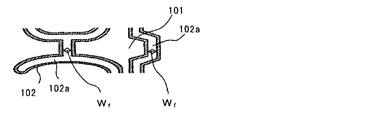
- FIG. 2 is a cross-sectional view schematically showing a part of the porous aluminum body of FIG.
- the aluminum porous body has a plurality of fiber portions 102 and cell-like pores 101 surrounded by the plurality of fiber portions 102.
- An opening (not shown) is formed between the adjacent holes 101, and the adjacent holes communicate with each other to form a continuous gap.
- Porous aluminum skeleton i.e., fiber section 102 that forms a skeleton
- W f width
- the average pore diameter of the three-dimensional network skeleton (average diameter of cellular pores communicating with each other) is, for example, 50 to 1000 ⁇ m, preferably 100 to 100 ⁇ m.
- the thickness is 900 ⁇ m, more preferably 350 to 900 ⁇ m.
- the average pore diameter is preferably smaller than the thickness of the aluminum porous body before compression.
- Aluminum porous body has a large specific surface area. Therefore, when an aluminum porous body is used as a carrier, a large amount of a support (electrode mixture, catalyst composition, etc.) can be attached to a wide area of the surface of the aluminum porous body including the surface in the voids of the aluminum porous body. Moreover, since the contact area between the porous aluminum body and the support is large and a high porosity can be maintained while the support is filled in the voids, it is easy to increase the utilization rate of the support.
- a support electrode mixture, catalyst composition, etc.
- the conductivity of the electrode is usually increased by adding a conductive additive to the electrode mixture, but by using the aluminum porous body as described above, Even if the addition amount of the conductive assistant is reduced, it is easy to ensure high conductivity. Therefore, when it uses for an electrode, an output and / or energy density (and capacity
- the specific surface area of the porous aluminum is, for example, 100 ⁇ 700cm 2 / g, preferably 150 ⁇ 650cm 2 / g, more preferably 200 ⁇ 600cm 2 / g.
- the width of the cavity inside the skeleton of the porous aluminum body before compression (specifically, the width W f of the cavity in FIG. 2) is an average value, for example, 0.5 to 5 ⁇ m, preferably 1 to 4 ⁇ m, or 2 to 3 ⁇ m.
- an electrode is formed by compressing in the thickness direction after filling the electrode mixture with the aluminum mixture.
- the skeleton of the porous aluminum body is slightly crushed in the thickness direction, and the cavities in the skeleton are also crushed.
- the electrolyte can circulate through the cavity in the skeleton in the electricity storage device.
- the porous aluminum body according to the embodiment of the present invention has a high porosity and a bulky three-dimensional network skeleton, the fiber parts forming the skeleton are close to each other in the thickness direction.
- High conductivity Such a porous aluminum body can be used in various applications such as filters, various carriers or substrates, and current collectors for power storage devices, using its special structure. In particular, it is useful in applications where high conductivity is required, such as current collectors for power storage devices.
- the above-mentioned aluminum porous body according to the embodiment of the present invention assumes a state where no electrode active material is attached. That is, the aluminum porous body can be used as an electrode current collector in the electrode of the electricity storage device, but preferably has the above-described characteristics before the electrode active material is attached.
- An electrode for an electricity storage device is formed by filling the aluminum porous body as an electrode current collector with an electrode mixture and further compressing (or rolling) the aluminum porous body in the thickness direction. The Due to the compression, the apparent density, porosity, ratio F t / F p , average pore diameter, etc. of the current collector in the electrode change as compared with those of the aluminum porous body.
- the aluminum porous body is further compressed in the thickness direction in addition to the three-dimensional network of porous aluminum bodies.
- the fiber parts of the aluminum porous body are closer to each other, and the distance between the fiber part and the electrode active material particles is further reduced. Therefore, the electrode has high conductivity.
- the electrolyte can be sufficiently retained in the vicinity of the electrode active material. By using such an electrode, the output of the electricity storage device can be increased.
- the electrode mixture is usually used in the form of a slurry containing the components of the electrode mixture (electrode active material, conductive additive, binder, etc.).
- the electrode mixture slurry is obtained by dispersing the components of the electrode mixture in a dispersion medium.
- the dispersion medium for example, water or the like is used in addition to an organic solvent such as N-methyl-2-pyrrolidone (NMP).
- NMP N-methyl-2-pyrrolidone
- the dispersion medium is removed by drying during the manufacturing process of the electrode (for example, after the slurry is filled in the current collector and / or after rolling).
- the electrode mixture can be filled in the aluminum porous body by a known method.
- the electrode mixture includes an electrode active material as an essential component, and can include a conductive additive and / or a binder as an optional component.
- the conductivity of the electrode can be further improved.
- a binder in the electrode mixture, the space between the electrode active material particles, between the electrode active material particles and the conductive auxiliary agent, and between the electrode active material particles or the conductive auxiliary agent and the current collector are further strengthened. Can be bound.
- the electrode active material can be appropriately selected according to the polarity of the electrode, the type of the electricity storage device, and the like.
- the electricity storage device includes a first electrode, a second electrode having a polarity opposite to that of the first electrode, a separator interposed therebetween, and an electrolyte, and at least the first electrode is used as the first electrode.
- a well-known thing can be used as a 2nd electrode according to the kind of electrical storage device, you may use said electrode.
- the second electrode includes a second electrode active material.
- the power storage device is not particularly limited as long as an aluminum current collector can be used.
- a capacitor such as a lithium ion capacitor or EDLC; a nonaqueous electrolyte such as a lithium ion secondary battery or a sodium ion secondary battery A secondary battery etc. can be illustrated.
- the separator included in the electricity storage device can be appropriately selected according to the type of the electricity storage device.
- the separator has ion permeability and is interposed between the first electrode and the second electrode, and physically separates them to prevent a short circuit.
- the separator has a porous structure and allows ions to pass through by holding an electrolyte in the pores.
- a material of the separator for example, polyolefin such as polyethylene and polypropylene; polyester such as polyethylene terephthalate; polyamide; polyimide; cellulose; glass fiber and the like can be used.
- the average pore diameter of the separator is not particularly limited and is, for example, about 0.01 to 5 ⁇ m.
- the thickness of the separator is not particularly limited, and is about 10 to 100 ⁇ m, for example.
- the configuration of the electrode and the electricity storage device will be described in more detail by taking a lithium ion capacitor, an EDLC, and a nonaqueous electrolyte secondary battery as examples.
- the first electrode is a positive electrode.
- the electrode according to the embodiment of the present invention is used as a positive electrode.
- the first electrode active material (that is, the positive electrode active material) contained in the positive electrode that is the first electrode includes at least a material that reversibly carries an anion.
- the positive electrode active material may include a material that reversibly supports anions and cations.
- the positive electrode active material reversibly carry anions and lithium ions.
- Materials that reversibly carry anions (and cations) include materials that adsorb and desorb anions (and cations) and materials that occlude and release (or insert and desorb) anions (and cations). .
- the former is a material that causes a non-Faraday reaction during charging and discharging
- the latter is a material that causes a Faraday reaction during charging and discharging.
- porous carbon materials such as activated carbon, nanoporous carbon, mesoporous carbon, microporous carbon, and carbon nanotube.
- the first porous carbon material may be activated or may not be activated.
- These 1st porous carbon materials can be used individually by 1 type or in combination of 2 or more types.
- activated carbon, nanoporous carbon, and the like are preferable. Note that porous carbon having fine pores on the order of sub nm to sub ⁇ m is referred to as nanoporous carbon.
- the first electrode active material can further contain other active materials as required in addition to the first porous carbon material.
- the content of the first porous carbon material in the first electrode active material is preferably more than 50% by mass, and may be 80% by mass or more or 90% by mass or more.
- the content of the first porous carbon material in the first electrode active material is 100% by mass or less.
- the content of activated carbon and nanoporous carbon in the first electrode active material is preferably in such a range. It is also preferable that the first electrode active material contains only the first porous carbon material (particularly activated carbon and / or nanoporous carbon).
- nanoporous carbon known ones used for lithium ion capacitors can be used, for example, those obtained by heating metal carbides such as silicon carbide and titanium carbide in an atmosphere containing chlorine gas. Also good.
- the activated carbon known ones used for lithium ion capacitors can be used.
- the raw material of activated carbon include wood; coconut shells; pulp waste liquid; coal or coal-based pitch obtained by thermal decomposition thereof; heavy oil or petroleum-based pitch obtained by thermal decomposition thereof; phenol resin and the like.
- the carbonized material is generally then activated.
- the activation method include a gas activation method and a chemical activation method.
- the average particle diameter of the activated carbon is not particularly limited, but is preferably 20 ⁇ m or less.
- the specific surface area is not particularly limited, but is preferably about 800 to 3000 m 2 / g. When the specific surface area is in such a range, it is advantageous for increasing the capacitance of the lithium ion capacitor, and the internal resistance can be reduced.
- the type of the conductive auxiliary agent is not particularly limited, and carbon black such as acetylene black and ketjen black; graphite (natural graphite such as flake graphite and earthy graphite; artificial graphite and the like); conductive compound such as ruthenium oxide A conductive fiber such as carbon fiber and metal fiber.
- the amount of the conductive assistant is, for example, 0 to 30 parts by mass, preferably 0 to 20 parts by mass with respect to 100 parts by mass of the first electrode active material. When the amount of the conductive auxiliary is within such a range, it is easy to increase the density of the electrode active material while ensuring the conductivity of the electrode mixture.
- the amount of the conductive auxiliary is 5 parts by mass or less (for example, 0 to 5 parts by mass), or 3 parts by mass or less (for example, 0 to 3 parts by mass) with respect to 100 parts by mass of the first electrode active material. You can also
- the type of the binder is not particularly limited.
- a fluorine resin such as polyvinylidene fluoride (PVDF) or polytetrafluoroethylene
- a chlorine-containing vinyl resin such as polyvinyl chloride
- a polyolefin resin such as polyethylene
- a rubbery heavy material such as styrene butadiene rubber.
- Polyvinyl pyrrolidone polyvinyl alcohol
- cellulose derivatives [cellulose ethers such as carboxymethyl cellulose (carboxyalkyl cellulose and the like)] and the like can be used.
- the amount of the binder is not particularly limited, and can be selected from the range of, for example, about 0.5 to 15 parts by mass, preferably 1 to 12 parts by mass, more preferably 1 to 10 parts per 100 parts by mass of the first electrode active material. A mass part may be sufficient. In the embodiment of the present invention, since a three-dimensional network current collector is used, even if the amount of the binder is small, a large amount of electrode mixture can be held on the current collector.
- the amount of the binder can be 5 parts by mass or less (for example, 1 to 5 parts by mass) with respect to 100 parts by mass of the first electrode active material, and may be 2 to 4 parts by mass.
- the thickness of the positive electrode can be appropriately selected from the range of 50 to 2000 ⁇ m, for example.
- the negative electrode that is the second electrode includes a second electrode active material (that is, a negative electrode active material) and can include a second electrode current collector (that is, a negative electrode current collector) that holds the second electrode active material.
- the negative electrode current collector may be a metal foil, but is preferably a metal porous body from the viewpoint of increasing the capacity of the lithium ion capacitor.
- the porous metal body may have an aluminum porous body or a three-dimensional network skeleton (particularly, a hollow skeleton) similar to the state before the aluminum porous body is compressed.
- the material for the negative electrode current collector is preferably copper, copper alloy, nickel, nickel alloy, stainless steel, or the like.
- the negative electrode current collector can be produced according to the case of an aluminum porous body using these materials instead of aluminum or an aluminum alloy when the resin porous body is metal-coated.
- the obtained metal porous body may be compressed as in the case of the aluminum porous body, or may be used as a negative electrode current collector without being compressed.
- the negative electrode active material includes a material that reversibly carries lithium ions (specifically, occlusion and release, or insertion and desorption).
- materials that cause a Faraday reaction during charge and discharge for example, a carbon material that absorbs and releases lithium ions (also referred to as a second carbon material), and lithium titanium oxide (such as lithium titanate). Spinel type lithium titanium oxide etc.), silicon oxide, silicon alloy, tin oxide and tin alloy.
- the second carbon material include graphitizable carbon (soft carbon), non-graphitizable carbon (hard carbon), graphite (carbon materials having a graphite-type crystal structure such as artificial graphite and natural graphite), and the like. .
- a negative electrode active material may be used individually by 1 type, and may be used in combination of 2 or more type.
- the negative electrode active material preferably has a theoretical capacity of 300 mAh / g or more.
- the second carbon material is preferable, and graphite and / or hard carbon is particularly preferable.
- the content of the second carbon material in the negative electrode active material is preferably more than 50% by mass, and may be 80% by mass or more or 90% by mass or more. Content of the 2nd carbon material in a negative electrode active material is 100 mass% or less. In particular, the content of graphite and / or hard carbon in the negative electrode active material is preferably within such a range. It is also preferable that the negative electrode active material contains only the second carbon material (particularly graphite and / or hard carbon).
- the negative electrode active material is preferably doped with lithium in advance (hereinafter referred to as pre-doping). This increases the voltage of the capacitor, which is further advantageous for increasing the capacity of the lithium ion capacitor. Note that the negative electrode capacity is preferably larger than the positive electrode capacity in order to suppress lithium deposition.
- Lithium doping can be performed by a known method.
- the doping of lithium may be performed when the capacitor is assembled.
- lithium metal foil is housed in a capacitor container together with a positive electrode, a negative electrode, and an electrolyte, and the assembled capacitor is kept warm in a constant temperature room at around 60 ° C., thereby elution of lithium ions from the lithium metal foil and The material can be doped.
- the negative electrode is, for example, coated or filled with a negative electrode mixture slurry containing a negative electrode active material on a negative electrode current collector, and then the dispersion medium contained in the negative electrode mixture slurry is removed, and further, if necessary, the negative electrode active material It can be obtained by compressing (or rolling) the current collector holding the. Moreover, as a negative electrode, you may use what is obtained by forming the deposit film of a negative electrode active material on the surface of a negative electrode collector by vapor phase methods, such as vapor deposition and sputtering.
- the negative electrode mixture slurry may contain a binder, a conductive aid and the like in addition to the negative electrode active material.
- a dispersion medium and a binder it can select suitably from what was illustrated about the electrode mixture of the 1st electrode.
- the amount of the binder with respect to 100 parts by mass of the negative electrode active material can be appropriately selected from the range of the amount of the binder with respect to 100 parts by mass of the first electrode active material.
- the conductive assistant is not particularly limited, and examples thereof include carbon black such as acetylene black and ketjen black; conductive compound such as ruthenium oxide; conductive fiber such as carbon fiber and metal fiber.
- the amount of the conductive auxiliary is, for example, 1 to 20 parts by mass, preferably 4 to 10 parts by mass with respect to 100 parts by mass of the negative electrode active material.
- the thickness of the negative electrode can be appropriately selected from the range of 50 to 2000 ⁇ m, for example.
- the thickness of the negative electrode is, for example, 100 to 2000 ⁇ m, preferably 200 to 1500 ⁇ m.
- the electrolyte includes cations and anions.
- the electrolyte of the lithium ion capacitor is preferably a non-aqueous electrolyte having lithium ion conductivity.
- a non-aqueous electrolyte contains lithium ions and anions.
- an electrolyte in which a salt (lithium salt) of lithium ions and anions is dissolved in a non-aqueous solvent (or an organic solvent), an ionic liquid containing lithium ions and anions, and the like are used.
- an ionic liquid is synonymous with the salt (molten salt) of a molten state, and is a liquid ionic substance comprised with an anion and a cation.
- the electrolyte can contain a nonaqueous solvent and / or an additive in addition to the ionic liquid, and the content of the ionic liquid in the electrolyte may be 60% by mass or more. Preferably, it is 80 mass% or more or 90 mass% or more.
- the concentration of the lithium salt or lithium ion in the electrolyte can be appropriately selected from the range of 0.3 to 5 mol / L, for example.
- the kind of the anion (first anion) constituting the lithium salt is not particularly limited.
- anion of fluorine-containing acid anion of fluorine-containing phosphate such as hexafluorophosphate ion (PF 6 ⁇ ); tetrafluoroboric acid Anion of fluorine-containing boric acid such as ion (BF 4 ⁇ )], anion of chlorine-containing acid [perchlorate ion (ClO 4 ⁇ ), etc.], anion of oxyacid having an oxalate group [bis (oxalato) borate ion Oxalatoborate ion such as (B (C 2 O 4 ) 2 ⁇ ); Oxalatophosphate ion such as tris (oxalato) phosphate ion (P (C 2 O 4 ) 3 ⁇ )], anion of fluoroalkanesulfonic acid [trifluoromethanesulfonate ion (CF 3 SO
- bissulfonylamide anion examples include bis (fluorosulfonyl) amide anion [bis (fluorosulfonyl) amide anion (N (SO 2 F) 2 ⁇ ) and the like], (fluorosulfonyl) (perfluoroalkylsulfonyl) amide Anion [(fluorosulfonyl) (trifluoromethylsulfonyl) amide anion ((FSO 2 ) (CF 3 SO 2 ) N ⁇ , etc.)], bis (perfluoroalkylsulfonyl) amide anion [bis (trifluoromethylsulfonyl) amide anion (N (SO 2 CF 3 ) 2 ⁇ ), bis (pentafluoroethylsulfonyl) amide anion (N (SO 2 C 2 F 5 ) 2 ⁇ ) and the like].
- the carbon number of the perfluoroalkyl group is preferably
- bis (fluorosulfonyl) amide anion FSA ⁇ : bis (fluorosulfonyl) amide anion
- bis (trifluoromethylsulfonyl) amide anion TFSA ⁇ : bis (trifluoromethylsulfonyl) amide anion
- bis ( A bis (perfluoroalkylsulfonyl) amide anion PFSA ⁇ : bis (perfluoroalkylsulfonyl) amide anion
- PFSA ⁇ bis (perfluoroalkylsulfonyl) amide anion
- the non-aqueous solvent contained in the electrolyte is not particularly limited, and known non-aqueous solvents used for lithium ion capacitors can be used.
- Non-aqueous solvents include, for example, cyclic carbonates such as ethylene carbonate, propylene carbonate, and butylene carbonate; chain carbonates such as dimethyl carbonate, diethyl carbonate, and ethyl methyl carbonate; cyclic carbonates such as ⁇ -butyrolactone. Etc. can be preferably used.
- a non-aqueous solvent may be used individually by 1 type, and may be used in combination of 2 or more type.
- the ionic liquid containing lithium ions contains lithium ions and anions (second anions).
- second anion various anions exemplified for the first anion, specifically, a bissulfonylamide anion, an anion of a fluorine-containing acid, an anion of a chlorine-containing acid, an anion of an oxyacid having an oxalate group, a fluoroalkanesulfonic acid Can be used.
- a 2nd anion can be used individually by 1 type or in combination of 2 or more types.
- the second anion preferably contains at least a bissulfonylamide anion.
- the content of the bissulfonylamide anion in the second anion is, for example, 80 to 100 mol%, preferably 90 to 100 mol%.
- the ionic liquid containing lithium ions may further contain a second cation in addition to the lithium ions (first cation).
- a second cation an inorganic cation other than lithium, for example, sodium ion, magnesium ion, calcium ion, ammonium cation or the like may be used, but an organic cation is preferable.
- a 2nd cation can be used individually by 1 type or in combination of 2 or more types.
- Examples of the organic cation used as the second cation include a cation derived from an aliphatic amine, an alicyclic amine, or an aromatic amine (for example, a quaternary ammonium cation), and a cation having a nitrogen-containing heterocycle ( That is, nitrogen-containing organic onium cations such as cations derived from cyclic amines; sulfur-containing onium cations; phosphorus-containing onium cations, and the like.
- nitrogen-containing organic onium cations those having pyrrolidine, pyridine, or imidazole as the nitrogen-containing heterocyclic skeleton are preferable.
- the quaternary ammonium cation include tetraalkylammonium cation, ethyltrimethylammonium cation, hexyltrimethylammonium cation, tetraethylammonium cation (TEA + : tetraethylammonium cation), and methyltriethylammonium cation (TEMA + : methyltriethylammonium cation).
- TAA + tetraethylammonium cation
- TEMA + methyltriethylammonium cation
- the organic onium cation having a pyrrolidine skeleton preferably has two alkyl groups on one nitrogen atom constituting the pyrrolidine ring.
- Examples of such organic onium cations include 1,1-dimethylpyrrolidinium cation, 1,1-diethylpyrrolidinium cation, 1-ethyl-1-methylpyrrolidinium cation, and 1-methyl-1-propyl.
- Pyrrolidinium cation (MPPY + : 1-methyl-1-pyrrolidinium cation), 1-butyl-1-methylpyrrolidinium cation (MBPY + : 1-butyl-1-methylpyrrolidinium cation), 1-ethyl-1-propyl Examples include pyrrolidinium cation.
- the organic onium cation having a pyridine skeleton preferably has one alkyl group on one nitrogen atom constituting the pyridine ring.
- Examples of such organic onium cations include 1-alkylpyridinium cations such as 1-methylpyridinium cation, 1-ethylpyridinium cation, and 1-propylpyridinium cation.
- the organic onium cation having an imidazole skeleton preferably has one alkyl group on each of two nitrogen atoms constituting the imidazole ring.
- organic onium cations include 1,3-dimethylimidazolium cation, 1-ethyl-3-methylimidazolium cation (EMI + : 1-ethyl-3-methylimidazolium cation), 1-methyl-3- Propylimidazolium cation, 1-butyl-3-methylimidazolium cation (BMI + : 1-butyl-3-methylimidazolium cation), 1-ethyl-3-propylimidazolium cation, 1-butyl-3-ethylimidazolium cation Etc.
- imidazolium cations having a methyl group and an alkyl group having 2 to 4 carbon atoms such as EMI + and BMI + are preferable.
- the 1st electrode active material (or positive electrode active material) contained in a positive electrode contains the material which carry
- the first electrode active material preferably includes a material that reversibly supports anions and cations.
- a porous carbon material (third porous carbon material) is preferable as the material that reversibly supports at least anions.
- the second electrode active material (or negative electrode active material) included in the second electrode (or negative electrode) includes a material (for example, a porous carbon material (fourth porous carbon material)) that reversibly supports cations.
- the first electrode active material (or negative electrode active material) included in the negative electrode includes a material (for example, a porous carbon material (fifth porous carbon material)) that reversibly supports cations, and the second electrode active material ( Alternatively, the positive electrode active material) includes at least a material that reversibly supports an anion.
- the second electrode active material may include a material that reversibly carries anions and cations. As such a material, a porous carbon material (sixth porous carbon material) is preferable.
- Examples of the material that reversibly supports cations and / or anions include materials that adsorb and desorb cations and / or anions, and materials that occlude and release (or insert and desorb) cations and / or anions. It can be illustrated.
- the former is a material that causes a non-Faraday reaction during charging and discharging
- the latter is a material that causes a Faraday reaction during charging and discharging.
- the porous carbon materials exemplified as the first porous carbon material of the lithium ion capacitor can be used.
- the porous carbon materials activated carbon, nanoporous carbon, and the like are preferable.
- the third porous carbon material and the fourth porous carbon material may be the same or different.
- the fifth porous carbon material and the sixth porous carbon material may be the same or different.
- Each of the positive electrode active material and the negative electrode active material can further contain other active materials as necessary in addition to the porous carbon material.
- Content of the said porous carbon material in a positive electrode active material or a negative electrode active material can be suitably selected from the range similar to content of the porous carbon material in the 1st electrode active material described about the lithium ion capacitor.
- the types of the conductive auxiliary agent and binder and the amounts of these components relative to the electrode active material can also be appropriately selected from the ranges described for the first electrode of the lithium ion capacitor.
- the second electrode can be produced according to the case of the positive electrode of the lithium ion capacitor.
- the thickness of the second electrode can be selected from the same range as the positive electrode of the lithium ion capacitor.
- the electrolyte used for EDLC may contain water or a non-aqueous electrolyte.
- the electrolyte includes a cation and an anion.
- As an electrolyte in addition to an electrolyte in which a salt of a cation (third cation) and an anion (third anion) is dissolved in a non-aqueous solvent (or an organic solvent), a cation (fourth cation) and an anion (fourth anion)
- a non-aqueous electrolyte such as an ionic liquid containing is preferably used.
- the concentration of the cation in the electrolyte can be appropriately selected from the range of 0.3 to 5 mol / L, for example.
- Examples of the third cation include inorganic cations such as lithium ion, sodium ion, magnesium ion, calcium ion, and ammonium cation; and the same organic cation exemplified as the second cation of the lithium ion capacitor.
- the third cation may contain one kind of cation or may contain two or more kinds of anions.
- the third cation preferably contains at least an organic cation. Of the organic cations, quaternary ammonium cations such as TEA + and TEMA + are preferable.
- the third anion can be appropriately selected from those exemplified as the first anion of the lithium ion capacitor.
- the third anion may include one kind of anion or two or more kinds of anions.
- As a nonaqueous solvent it can select suitably from what was illustrated about the lithium ion capacitor.
- the fourth cation contained in the ionic liquid can be appropriately selected from those exemplified for the third cation.
- the fourth cation may contain one kind of cation or may contain two or more kinds of cations.
- the fourth cation preferably contains at least an organic cation.
- imidazolium cations such as EMI + and BMI + are preferred.
- the fourth anion contained in the ionic liquid can be appropriately selected from those exemplified as the second anion of the lithium ion capacitor.
- the fourth anion may include one kind of anion or two or more kinds of anions.
- the fourth anion preferably includes at least a bissulfonylamide anion.
- the content of the bissulfonylamide anion in the fourth anion can be selected from the same range as in the case of the second anion.
- Content of the ionic liquid in electrolyte can be suitably selected from the range illustrated about the lithium ion capacitor.
- the electrode according to the embodiment of the present invention may be used for the second electrode (negative electrode), but is preferably used for the first electrode (positive electrode).
- the first electrode active material (positive electrode active material) included in the first electrode (positive electrode) includes a material that reversibly carries (specifically, occludes and releases, or inserts and desorbs) alkali metal ions. . Such a material is a material that causes a Faraday reaction during charging and discharging.
- Such materials include metal chalcogen compounds (sulfides, oxides, etc.), alkali metal-containing transition metal oxides (lithium-containing transition metal oxides, sodium-containing transition metal oxides), alkali metal-containing transition metal phosphates. (Such as iron phosphate having an olivine structure). These materials can be used singly or in combination of two or more.
- the second electrode active material (negative electrode active material) included in the second electrode (negative electrode) includes a material that reversibly carries (specifically, occludes and releases) the alkali metal ions. Such a material is a material that causes a Faraday reaction during charging and discharging.
- the negative electrode active material include sodium titanium oxide (such as spinel sodium titanium oxide such as sodium titanate) in addition to those exemplified as the negative electrode active material of the lithium ion capacitor.
- a negative electrode active material can be suitably selected according to the kind of alkali metal ion.
- the negative electrode active material may be doped with alkali metal ions such as lithium according to the case of the lithium ion capacitor.
- the negative electrode as the second electrode includes a negative electrode active material and can include an electrode current collector (that is, a negative electrode current collector) that holds the negative electrode active material.
- an electrode current collector that is, a negative electrode current collector
- the same as the negative electrode current collector of the lithium ion capacitor can be used.
- the negative electrode can be produced according to the case of the negative electrode of a lithium ion capacitor.
- the thickness of the negative electrode can be selected from the same range as the negative electrode of the lithium ion capacitor.
- the electrode mixture (negative electrode mixture) used for the negative electrode can contain a conductive additive and / or a binder.
- a binder it can select suitably from what was illustrated about the positive electrode of the lithium ion capacitor.
- the conductive assistant include those exemplified for the negative electrode of the lithium ion capacitor, and nanocarbons such as carbon nanotubes.
- a conductive support agent can be used individually by 1 type or in combination of 2 or more types. The amounts of the conductive agent and the binder with respect to the negative electrode active material are the same as in the case of the lithium ion capacitor.
- the electrolyte used for the nonaqueous electrolyte secondary battery includes an alkali metal ion and an anion.
- a non-aqueous electrolyte can be used.
- an electrolyte in which a salt (alkali metal salt) of an alkali metal ion and an anion (fifth anion) is dissolved in a non-aqueous solvent (or an organic solvent) is used.
- an ionic liquid containing an alkali metal ion and an anion (sixth anion) is used.
- concentration of the alkali metal salt or alkali metal ion in the electrolyte can be appropriately selected from the range of 0.5 to 3 mol / L, for example.
- the alkali metal ion can be appropriately selected from lithium ion, sodium ion, potassium ion, rubidium ion, cesium ion, and the like according to the type of the nonaqueous electrolyte secondary battery.
- the electrolyte in a lithium ion secondary battery, the electrolyte includes lithium ions as alkali metal ions, and in a sodium ion secondary battery, the electrolyte includes sodium ions as alkali metal ions.
- the electrolyte may contain other alkali metal ions in addition to lithium ions and / or sodium ions.
- the fifth anion constituting the alkali metal salt can be appropriately selected from those exemplified as the first anion of the lithium ion capacitor.
- One alkali metal salt may be used alone, or two or more alkali metal salts having different types of fifth anions may be used in combination.
- As a nonaqueous solvent it can select suitably from what was illustrated about the lithium ion capacitor.
- the sixth anion contained in the ionic liquid can be appropriately selected from those exemplified as the second anion of the lithium ion capacitor.
- the sixth anion may include one kind of anion or two or more kinds of anions.
- the sixth anion preferably contains at least a bissulfonylamide anion.
- the content of the bissulfonylamide anion in the sixth anion can be selected from the same range as in the second anion.
- Content of the ionic liquid in electrolyte can be suitably selected from the range illustrated about the lithium ion capacitor.
- the power storage device includes, for example, (a) a step of forming an electrode group with a first electrode, a second electrode, and a separator interposed between the first electrode and the second electrode, and (b) an electrode group and an electrolyte. It can manufacture by passing through the process of accommodating in a cell case.
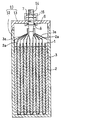
- FIG. 3 is a longitudinal sectional view schematically showing an electricity storage device according to an embodiment of the present invention.
- the power storage device includes a stacked electrode group, an electrolyte (not shown), and a rectangular aluminum case 10 for housing them.
- the case 10 includes a bottomed container body 12 having an upper opening and a lid 13 that closes the upper opening.
- an electrode group When assembling an electricity storage device, first, an electrode group is configured by laminating a positive electrode (first electrode) 2 and a negative electrode (second electrode) 3 with a separator 1 interposed between them. The electrode group thus formed is inserted into the container body 12 of the case 10. Thereafter, a step of injecting an electrolyte into the container body 12 and impregnating the electrolyte in the gaps of the separator 1, the positive electrode 2 and the negative electrode 3 constituting the electrode group is performed.
- the electrolyte includes an ionic liquid
- the electrode group may be impregnated in the electrolyte, and then the electrode group including the electrolyte may be accommodated in the container body 12.
- a safety valve 16 is provided for releasing gas generated inside when the internal pressure of the case 10 rises.
- An external positive terminal 14 that penetrates the lid 13 is provided near the one side of the lid 13 with the safety valve 16 in the center, and an external that penetrates the lid 13 is located near the other side of the lid 13.
- a negative terminal (not shown) is provided.
- the stacked electrode group is composed of a plurality of positive electrodes 2, a plurality of negative electrodes 3, and a plurality of separators 1 interposed therebetween, all in the form of a rectangular sheet.
- the separator 1 is formed in a bag shape so as to surround the positive electrode 2, but the form of the separator is not particularly limited.
- the plurality of positive electrodes 2 and the plurality of negative electrodes 3 are alternately arranged in the stacking direction within the electrode group.
- a positive electrode lead piece 2 a may be formed at one end of each positive electrode 2.
- the plurality of positive electrodes 2 are connected in parallel by bundling the positive electrode lead pieces 2 a of the plurality of positive electrodes 2 and connecting them to the external positive terminal 14 provided on the lid 13 of the case 10.
- a negative electrode lead piece 3 a may be formed at one end of each negative electrode 3.
- a plurality of negative electrodes 3 are connected in parallel by bundling the negative electrode lead pieces 3a of the plurality of negative electrodes 3 and connecting them to an external negative terminal provided on the lid 13 of the case 10.
- the bundle of the positive electrode lead pieces 2a and the bundle of the negative electrode lead pieces 3a are desirably arranged on the left and right sides of one end face of the electrode group with an interval so as to avoid mutual contact.
- the external positive terminal 14 and the external negative terminal are both columnar, and at least a portion exposed to the outside has a thread groove.
- a nut 7 is fitted in the screw groove of each terminal, and the nut 7 is fixed to the lid 13 by rotating the nut 7.
- a flange 8 is provided in a portion of each terminal accommodated in the case 10, and the flange 8 is fixed to the inner surface of the lid 13 through a washer 9 by the rotation of the nut 7.
- the electrode group is not limited to a laminated type, and may be formed by winding a positive electrode and a negative electrode through a separator.
- the dimension of the negative electrode may be made larger than that of the positive electrode from the viewpoint of preventing lithium from being deposited on the negative electrode.
- a plurality of fiber parts containing aluminum or an aluminum alloy is a porous aluminum body having a three-dimensionally linked three-dimensional network skeleton, and the mass per unit volume is 30 to 1100 mg / cm 3 , and the number F t of the fiber portions per unit length of the thickness direction in the thickness direction of the cross section of the aluminum porous body, and the number F p of the fiber portion of the per unit length in the plane direction at the surface of the porous aluminum
- the aluminum porous body has a ratio F t / F p of 1.4 or more.
- an aluminum porous body has high conductivity, when it is used as an electrode current collector of an electricity storage device, the output of the electrode and the electricity storage device can be increased.
- Appendix 2 The skeleton of the aluminum porous body of Appendix 1 is hollow, the mass per unit volume is 175 to 1000 mg / cm 3 , the porosity is 50 to 99% by volume, and the ratio F t / F p It is 1.9 to 10 and the number F t of the fiber unit is a 6 to 25 present / mm, preferably has a thickness of 0.10 ⁇ 0.65 mm.
- Such an aluminum porous body can further improve electrical conductivity.
- the foam having the conductive layer formed on the surface was immersed in a molten salt aluminum plating bath, and a direct current having a current density of 3.6 A / dm 2 was applied for 90 minutes to form an aluminum layer.
- the mass of the aluminum layer per apparent area of the foam was 150 g / m 2 .
- the molten salt aluminum plating bath contained 33 mol% 1-ethyl-3-methylimidazolium chloride and 67 mol% aluminum chloride, and the temperature was 40 ° C.
- the foam with the aluminum layer formed on the surface was immersed in a lithium chloride-potassium chloride eutectic molten salt at 500 ° C., and a negative potential of ⁇ 1 V was applied for 30 minutes to decompose the foam.
- the obtained aluminum porous body was taken out from the molten salt, cooled, washed with water, and dried. The dried product was further compressed in the thickness direction to obtain a porous aluminum body (a1).
- the obtained aluminum porous body (a1) has a three-dimensional network-like porous structure in which the pores communicate with each other, reflecting the pore shape of the foam, and the apparent density (mass per unit volume) is 210 mg. / Cm 3 , the porosity was 92% by volume, the average pore diameter was 400 ⁇ m, the specific surface area (BET specific surface area) by the BET method was 400 cm 2 / g, and the thickness was 0.6 mm. . Further, the three-dimensional network skeleton of the aluminum porous body had a communication hole-like cavity formed by removing the foam inside.
- a photomicrograph of one main surface of the aluminum porous body and a cross section in the thickness direction was taken, the number of fiber portions F t and F p per unit length was determined, and the ratio F t / F p was calculated. 6.
- the resistivity of the obtained aluminum porous body was measured as follows. The resistance was measured by a four-terminal method while pressing a test piece having a width of 1 cm against the terminal with a load of 100 g / cm 2 . The distance between the terminals was 3.3 cm.
- Examples 2 to 6 and Comparative Examples 1 to 3 The porous aluminum bodies (a2) to (a6) and (b1) were prepared in the same manner as in Example 1 except that the porosity, the number of cells, and the compression ratio when the dried product was compressed were appropriately adjusted. ) To (b3) were prepared, and the resistivity was measured. Table 1 shows the resistivity of the porous aluminum body together with the apparent density and porosity of the porous aluminum bodies of Examples 1 to 6 and Comparative Examples 1 to 3, along with the number F t of fibers and the ratio F t / F p .
- (A1) to (a6) are the aluminum porous bodies of Examples 1 to 6, respectively
- (b1) to (b3) are the aluminum porous bodies of Comparative Examples 1 to 3, respectively.
- the ratio F t / F p is less than 1.4 and 1.4 or more, the behavior of the resistivity is different, and the ratio F t / F p is 1.4 or more. It can be seen that the resistivity is particularly small. From the viewpoint of reducing the resistivity, the ratio F t / F p is more preferably 1.9 or more.
- Examples 7-12 and Comparative Examples 4-6 Using the aluminum porous bodies of Examples 1 to 6 and Comparative Examples 1 to 3 as current collectors, lithium ion capacitors were produced by the following procedure, and the output was evaluated.
- the obtained positive electrode mixture slurry was filled in a porous aluminum body using a die coater and dried at 100 ° C. for 30 minutes.
- the dried product was rolled using a pair of rolls to produce a positive electrode having a thickness of 160 ⁇ m.
- the foam with the Cu layer formed on the surface is heat-treated at 700 ° C. in an air atmosphere to decompose the foam, and then fired in a hydrogen atmosphere to reduce the oxide film formed on the surface.
- a copper porous body (negative electrode current collector) was obtained.
- the obtained negative electrode current collector has a three-dimensional network-like porous structure in which the pores communicate with each other, reflecting the pore shape of the foam, the porosity is 92% by volume, and the average pore diameter is 550 ⁇ m.
- the BET specific surface area was 200 cm 2 / g.
- the three-dimensional network copper skeleton had a communication hole-like cavity formed by removing the foam.
- the obtained negative electrode mixture slurry was filled into the current collector obtained in the step (a) using a die coater and dried at 100 ° C. for 30 minutes.
- the dried product was rolled using a pair of rolls to produce a negative electrode having a thickness of 120 ⁇ m.
- a single-cell electrode group was formed by laminating a positive electrode and a negative electrode with a cellulose separator (thickness: 60 ⁇ m) interposed between the positive electrode and the negative electrode. Further, a lithium separator is disposed on the negative electrode side of the electrode group with a polyolefin separator (a laminate of a polyethylene microporous membrane and a polypropylene microporous membrane), and the obtained laminate is made of an aluminum laminate sheet. It accommodated in the produced cell case.
- a nonaqueous electrolyte was injected into the cell case, and impregnated into the positive electrode, the negative electrode, and the separator.
- a solution in which LiPF 6 as a lithium salt was dissolved in a mixed solvent containing ethylene carbonate and diethyl carbonate at a mass ratio of 1: 1 so as to have a concentration of 1.0 mol / L was used.
- the cell case was sealed while reducing the pressure with a vacuum sealer.
- the negative electrode lead wire and the lithium electrode lead wire are connected to a power source outside the cell case, and charged with a current of 0.2 mA / cm 2 to a potential of 0 V with respect to metallic lithium.
- a lithium ion capacitor (A1) was produced by pre-doping. Then, it charged / discharged with the electric current of 1 mA / cm ⁇ 2 >, and the discharge capacity (initial capacity) at this time was measured.
- the discharge capacity was measured by the following procedure using the obtained lithium ion capacitor.
- the battery was charged to 3.8V at a current of 2C with respect to the initial capacity, and discharged at a current of 2C or 50C until the voltage reached 2.2V.
- the discharge capacity (mAh) at this time was determined.
- the discharge capacity when discharged at a current of 2 C was “discharge capacity A”, and the discharge capacity when discharged at a current of 50 C was “discharge capacity B”.
- the output characteristics of the lithium ion capacitor were evaluated.
- Table 2 shows the results of Examples and Comparative Examples.
- the lithium ion capacitors of Examples 7 to 12 using the aluminum porous bodies (a1) to (a6) were designated as (A1) to (A6), respectively, and the aluminum porous bodies (b1) to (b3) were used.
- the lithium ion capacitors of Comparative Examples 4 to 6 were designated as (B1) to (B3), respectively.
- the lithium ion capacitors (A1) to (A6) using the aluminum porous bodies (a1) to (a6) show output characteristics of 82% or more, and the aluminum porous bodies (b1) to (b3 High output characteristics were obtained as compared with lithium ion capacitors (B1) to (B3) using
- the porous aluminum body according to the embodiment of the present invention can be used for various applications such as filters, various carriers or substrates, and current collectors for power storage devices. Since the aluminum porous body has high conductivity, it is particularly useful in applications where high conductivity is required, such as a current collector of an electricity storage device.
Abstract
This aluminum porous body has a three-dimensional network skeleton wherein a plurality of fiber parts containing aluminum or an aluminum alloy are three-dimensionally connected with each other. This aluminum porous body has a mass per unit volume of 30-1,100 mg/cm3, and the ratio of the number of fiber parts (Ft) per unit length in the thickness direction in a cross-section of the aluminum porous body in the thickness direction to the number of fiber parts (Fp) per unit length in the plane direction in the surface of the aluminum porous body, namely Ft/Fp is 1.4 or more.
Description
本発明は、アルミニウム多孔体、このアルミニウム多孔体を用いて得られる蓄電デバイス用電極および蓄電デバイスに関する。
The present invention relates to an aluminum porous body, an electrode for an electricity storage device obtained using the aluminum porous body, and an electricity storage device.
金属多孔体は、フィルタ、触媒担体、蓄電デバイス用の集電体など、様々な分野で使用されている。金属多孔体には、例えば、パンチングメタルシート、または金属メッシュなどの二次元的な構造を有するものの他、三次元網目構造を有するものなどが含まれる。
Metal porous bodies are used in various fields such as filters, catalyst carriers, and current collectors for electricity storage devices. Examples of the metal porous body include those having a three-dimensional network structure in addition to those having a two-dimensional structure such as a punching metal sheet or a metal mesh.
特許文献1には、三次元網目構造を有するアルミニウム多孔質材が提案されている。特許文献2には、発泡体の形状を有し、かつアルミニウムおよびチタンを含む金属多孔体を、リチウムイオン二次電池の正極集電体として利用することが提案されている。これらの特許文献では、アルミニウムを含む金属多孔体に、正極活物質を充填し、乾燥し、圧縮成形することにより、リチウムイオン二次電池用の正極を作製している。
Patent Document 1 proposes an aluminum porous material having a three-dimensional network structure. Patent Document 2 proposes to use a porous metal body having a foam shape and containing aluminum and titanium as a positive electrode current collector of a lithium ion secondary battery. In these patent documents, a positive electrode for a lithium ion secondary battery is produced by filling a porous metal body containing aluminum with a positive electrode active material, drying, and compression molding.
三次元網目構造を有する金属多孔体では、三次元網目構造が嵩高く、気孔率が高いため、例えば、電極または触媒担体などの用途では、網目構造の内部に、電極合剤または触媒組成物を多量に充填することができる。その一方、金属多孔体は、高い気孔率を有するため、金属多孔体中に含まれる金属の質量比率が小さい。従って、三次元網目構造を有する金属多孔体では、導電性が低下し易くなり、高い導電性が求められる用途では問題となることがある。
In the porous metal body having a three-dimensional network structure, the three-dimensional network structure is bulky and the porosity is high. For example, in applications such as electrodes or catalyst carriers, an electrode mixture or a catalyst composition is placed inside the network structure. A large amount can be filled. On the other hand, since the metal porous body has a high porosity, the mass ratio of the metal contained in the metal porous body is small. Therefore, in the metal porous body having a three-dimensional network structure, the conductivity is likely to be lowered, which may cause a problem in applications where high conductivity is required.
蓄電デバイスの電極を作製する従来の方法では、特許文献1および特許文献2のように、電極合剤スラリーを、集電体の三次元網目構造内に充填した後に、乾燥してスラリー中の分散媒を除去し、次いで集電体の厚み方向に圧縮する。しかし、集電体の網目構造内には、既に電極合剤が充填されているため、集電体の圧縮率を大きくすることは難しく、導電性を大きく向上することは困難である。
In the conventional method for producing the electrode of the electricity storage device, as in Patent Document 1 and Patent Document 2, after the electrode mixture slurry is filled in the three-dimensional network structure of the current collector, it is dried and dispersed in the slurry. The medium is removed and then compressed in the thickness direction of the current collector. However, since the electrode mixture is already filled in the mesh structure of the current collector, it is difficult to increase the compressibility of the current collector, and it is difficult to greatly improve the conductivity.
本発明の目的は、高い導電性を有するアルミニウム多孔体、このアルミニウム多孔体を用いて得られる蓄電デバイス用電極および蓄電デバイスを提供することである。
An object of the present invention is to provide an aluminum porous body having high conductivity, an electrode for an electricity storage device and an electricity storage device obtained using the aluminum porous body.
本発明の一局面は、アルミニウムまたはアルミニウム合金を含む複数の繊維部が、三次元的に連結した三次元網目状の骨格を有するアルミニウム多孔体であって、単位体積当たりの質量は、30~1100mg/cm3であり、前記アルミニウム多孔体の厚み方向の断面における前記厚み方向の単位長さ当たりの前記繊維部の本数Ftと、前記アルミニウム多孔体の表面における面方向の単位長さ当たりの前記繊維部の本数Fpとの比Ft/Fpは、1.4以上であるアルミニウム多孔体に関する。
One aspect of the present invention is an aluminum porous body having a three-dimensional network skeleton in which a plurality of fiber parts including aluminum or an aluminum alloy are three-dimensionally connected, and the mass per unit volume is 30 to 1100 mg / Cm 3 , the number F t of the fiber portions per unit length in the thickness direction in the cross section in the thickness direction of the aluminum porous body, and the unit length in the surface direction on the surface of the aluminum porous body The ratio F t / F p to the number F p of fiber parts relates to a porous aluminum body having a ratio of 1.4 or more.
本発明の他の一局面は、電極集電体としての前記アルミニウム多孔体に、第1電極活物質を含む電極合剤を充填し、前記アルミニウム多孔体の厚み方向に圧縮することにより形成される蓄電デバイス用電極に関する。
Another aspect of the present invention is formed by filling the aluminum porous body as an electrode current collector with an electrode mixture containing a first electrode active material and compressing the aluminum porous body in the thickness direction of the aluminum porous body. The present invention relates to an electrode for an electricity storage device.
本発明のさらに他の一局面は、第1電極、前記第1電極と反対の極性を有する第2電極、前記第1電極と前記第2電極との間に介在するセパレータ、および電解質を含み、少なくとも前記第1電極は、上記蓄電デバイス用電極であり、前記第2電極は、第2電極活物質を含む蓄電デバイスに関する。
Still another aspect of the present invention includes a first electrode, a second electrode having a polarity opposite to that of the first electrode, a separator interposed between the first electrode and the second electrode, and an electrolyte. At least the first electrode is an electrode for the electricity storage device, and the second electrode relates to an electricity storage device containing a second electrode active material.
本発明の上記局面によれば、アルミニウム多孔体は、三次元網目構造を有するにも拘わらず、抵抗が低く、つまり、高い導電性を有する。このようなアルミニウム多孔体を、蓄電デバイスの電極集電体として用いると、電極および蓄電デバイスの高出力化が可能である。
According to the above aspect of the present invention, the aluminum porous body has a low resistance, that is, a high conductivity despite having a three-dimensional network structure. When such an aluminum porous body is used as an electrode current collector of an electricity storage device, the output of the electrode and the electricity storage device can be increased.
[発明の実施形態の説明]
最初に、本発明の実施形態の内容を列記して説明する。
本発明の一実施形態は、(1)アルミニウムまたはアルミニウム合金を含む複数の繊維部が、三次元的に連結した三次元網目状の骨格を有するアルミニウム多孔体であって、単位体積当たりの質量は、30~1100mg/cm3であり、前記アルミニウム多孔体の厚み方向の断面における前記厚み方向の単位長さ当たりの前記繊維部の本数Ftと、前記アルミニウム多孔体の表面における面方向の単位長さ当たりの前記繊維部の本数Fpとの比Ft/Fpは、1.4以上であるアルミニウム多孔体に関する。 [Description of Embodiment of the Invention]
First, the contents of the embodiment of the present invention will be listed and described.
One embodiment of the present invention is (1) an aluminum porous body having a three-dimensional network skeleton in which a plurality of fiber parts including aluminum or an aluminum alloy are three-dimensionally connected, and the mass per unit volume is 30 to 1100 mg / cm 3 , the number F t of fiber portions per unit length in the thickness direction in the cross section in the thickness direction of the porous aluminum body, and the unit length in the surface direction on the surface of the porous aluminum body The ratio F t / F p with respect to the number F p of fiber portions per thickness relates to a porous aluminum body having a ratio of 1.4 or more.
従来の三次元網目構造を有する金属多孔体では、気孔率を高めることで、軽量化できたり、および/または電極合剤または触媒組成物などを多量に充填することができたりするなど、様々な効果が得られる。その一方、金属多孔体の気孔率が高くなると、金属多孔体に含まれる金属の質量比率が小さくなるため、導電性が低下し易くなる。そのため、用途によっては、導電性の低下が問題となる場合がある。
In the conventional metal porous body having a three-dimensional network structure, it is possible to reduce the weight by increasing the porosity and / or to fill a large amount of the electrode mixture or the catalyst composition. An effect is obtained. On the other hand, when the porosity of the metal porous body is increased, the mass ratio of the metal contained in the metal porous body is decreased, so that the conductivity is easily lowered. Therefore, depending on the application, a decrease in conductivity may be a problem.
例えば、金属多孔体を、蓄電デバイスの電極集電体として用いる場合、従来の方法では、電極は、金属多孔体に電極合剤を充填した後、金属多孔体の厚み方向に圧縮することにより得られる。ところが、電極合剤を金属多孔体に充填した後に、金属多孔体を圧縮しても、圧縮率を高めることは困難である。圧縮率が低いと、金属多孔体の三次元網目構造の骨格を構成する骨となる部分、つまり、繊維部(または棒状部)の密度が高められず、互いに近接し難いため、導電性を高めにくい。
For example, when a metal porous body is used as an electrode current collector of an electricity storage device, in the conventional method, the electrode is obtained by filling the metal porous body with an electrode mixture and then compressing the metal porous body in the thickness direction. It is done. However, even if the metal porous body is compressed after filling the electrode mixture into the metal porous body, it is difficult to increase the compression rate. If the compression ratio is low, the density of the part that forms the skeleton of the three-dimensional network structure of the metal porous body, that is, the fiber part (or rod-like part) cannot be increased, and it is difficult to be close to each other. Hateful.
従来の方法で、金属多孔体の圧縮率を高めるには、電極合剤の充填量を少なくする必要がある。しかし、少ない量の電極合剤を、充填スペースが大きい金属多孔体に均一に充填することは難しい。
In order to increase the compressibility of the metal porous body by the conventional method, it is necessary to reduce the filling amount of the electrode mixture. However, it is difficult to uniformly fill a porous metal body having a large filling space with a small amount of the electrode mixture.
本発明の実施形態では、三次元網目構造の骨格を有するアルミニウム多孔体において、単位体積当たりの質量(または見かけ密度)を30~1100mg/cm3、比Ft/Fpを1.4以上とする。このような構成により、アルミニウム多孔体の骨格を形成する繊維部同士を近接させることができるため、導電性を高めることができる。
In an embodiment of the present invention, in a porous aluminum body having a three-dimensional network structure skeleton, the mass (or apparent density) per unit volume is 30 to 1100 mg / cm 3 , and the ratio F t / F p is 1.4 or more. To do. With such a configuration, since the fiber parts forming the skeleton of the porous aluminum body can be brought close to each other, the conductivity can be increased.
また、アルミニウム多孔体は、所定の厚みを有する多孔質シートの形状を有している。このようなアルミニウム多孔体に、電極合剤または触媒組成物などを充填する場合、アルミニウム多孔体の表面(具体的には、一方または両方の主面)から内部に充填される。アルミニウム多孔体の厚み方向の断面に比べて、表面(およびアルミニウム多孔体の面方向)では、繊維部間の距離が大きいため、電極合剤または触媒組成物などを充填し易い。よって、アルミニウム多孔体の見かけ密度が高いにも拘わらず、電極合剤または触媒組成物などを充填する場合にはより均一に充填することができる。
Also, the aluminum porous body has a shape of a porous sheet having a predetermined thickness. When such an aluminum porous body is filled with an electrode mixture or a catalyst composition, the aluminum porous body is filled from the surface (specifically, one or both main surfaces) of the aluminum porous body. Compared to the cross section in the thickness direction of the aluminum porous body, the surface (and the surface direction of the aluminum porous body) has a large distance between the fiber parts, and therefore it is easy to fill the electrode mixture or the catalyst composition. Accordingly, even when the apparent density of the porous aluminum body is high, the electrode mixture or the catalyst composition can be filled more uniformly.
なお、三次元網目状の骨格とは、アルミニウムまたはアルミニウム合金で形成された繊維部(または棒状部)を有し、繊維部が三次元的に連結して網目状のネットワークを形成した骨格またはその構造を指す。
The three-dimensional network skeleton has a fiber part (or rod-like part) formed of aluminum or an aluminum alloy, or a skeleton in which the fiber parts are connected three-dimensionally to form a network. Refers to the structure.
繊維部の本数Ftは、アルミニウム多孔体の厚み方向の断面において、所定長さ(例えば、0.1mm)を有する線分を厚み方向と平行に引いたとき、この線分と交わる繊維部の本数を単位長さ(例えば、1mm)当たりに換算したものを意味する。繊維部の本数Fpは、アルミニウム多孔体の表面において、所定長さ(例えば、0.1mm)を有する線分を、アルミニウム多孔体の面方向と平行に引いたとき、この線分と交わる繊維部の本数を単位長さ(例えば、1mm)当たりに換算したものを意味する。比Ft/Fpが1よりも大きい場合、アルミニウム多孔体の繊維部が、面方向に比べて、厚み方向において密に分布していることになる。繊維部の本数は、例えば、アルミニウム多孔体の厚み方向の断面または表面の光学顕微鏡写真などを用いて計測することができる。なお、アルミニウム多孔体の表面とは、所定の厚みを有する多孔質シートの形状を有するアルミニウム多孔体において、多孔質シートの一方の主面を指す。
Number F t of the fiber portion in the thickness direction of the cross section of the porous aluminum, a predetermined length (e.g., 0.1 mm) when drawn a line segment having a parallel to the thickness direction, the fibrous portion intersecting the segment This means that the number is converted per unit length (for example, 1 mm). The number of fiber portions F p is a fiber that intersects a line segment having a predetermined length (for example, 0.1 mm) on the surface of the aluminum porous body in parallel with the surface direction of the aluminum porous body. This means that the number of parts is converted per unit length (for example, 1 mm). When the ratio F t / F p is greater than 1, the fiber portions of the aluminum porous body are more densely distributed in the thickness direction than in the plane direction. The number of fiber parts can be measured using, for example, a cross section in the thickness direction of the porous aluminum body or an optical micrograph of the surface. The surface of the aluminum porous body refers to one main surface of the porous sheet in the aluminum porous body having the shape of the porous sheet having a predetermined thickness.
(2)好ましい態様では、前記アルミニウム多孔体の前記骨格は中空である。このようなアルミニウム多孔体は、軽量であるため有利である。アルミニウム多孔体の中空の骨格は、トンネル状またはチューブ状になっているため、蓄電デバイスの電極の作製に使用すると、蓄電デバイス内で電解質がより流通し易くなる。
(2) In a preferred embodiment, the skeleton of the porous aluminum body is hollow. Such an aluminum porous body is advantageous because it is lightweight. Since the hollow skeleton of the porous aluminum body has a tunnel shape or a tube shape, when it is used for producing an electrode of an electricity storage device, the electrolyte is more easily distributed in the electricity storage device.
(3)前記比Ft/Fpは、1.4~10であることが好ましい。比Ft/Fpがこのような範囲である場合、高い充填性を確保しながらも、導電性をさらに高めることができる。
(4)前記繊維部の本数Ftは、2~50本/mmであることが好ましい。Ftがこのような範囲である場合、高い充填性を確保しながらも、導電性を高め易い。 (3) The ratio F t / F p is preferably 1.4 to 10. When the ratio F t / F p is in such a range, the conductivity can be further enhanced while ensuring high filling properties.
(4) the number F t of the fiber unit is preferably 2 to 50 lines / mm. When Ft is in such a range, it is easy to improve conductivity while ensuring high filling properties.
(5)前記アルミニウム多孔体は、0.1~0.65mmの厚みを有することが好ましい。アルミニウム多孔体がこのような厚みを有することで、導電性をさらに高めることができる。
(5) The porous aluminum body preferably has a thickness of 0.1 to 0.65 mm. When the aluminum porous body has such a thickness, the conductivity can be further increased.
本発明の他の一実施形態は、(6)電極集電体としての前記アルミニウム多孔体に、第1電極活物質を含む電極合剤を充填し、前記アルミニウム多孔体の厚み方向に圧縮することにより形成される蓄電デバイス用電極に関する。アルミニウム多孔体は、電極合剤を充填する前の段階で、繊維部同士が近接しているため、高い導電性を有する。電極合剤を充填した後、アルミニウム多孔体をさらに圧縮することで、得られる電極の導電性をさらに高めることができる。電極の導電性が高まることで、蓄電デバイスを高出力化することができる。また、アルミニウム多孔体の厚み方向に比べて、面方向では、繊維部間の距離が大きいため、電極合剤を均一に充填し易い。
In another embodiment of the present invention, (6) the aluminum porous body as an electrode current collector is filled with an electrode mixture containing a first electrode active material, and compressed in the thickness direction of the aluminum porous body. It relates to an electrode for an electricity storage device formed by the above. The porous aluminum body has high conductivity because the fiber parts are close to each other before filling the electrode mixture. After filling the electrode mixture, the conductivity of the obtained electrode can be further increased by further compressing the porous aluminum body. By increasing the conductivity of the electrode, the power storage device can have high output. Moreover, since the distance between fiber parts is large in the surface direction compared to the thickness direction of the aluminum porous body, it is easy to uniformly fill the electrode mixture.
本発明のさらに他の一実施形態は、(7)第1電極、前記第1電極と反対の極性を有する第2電極、前記第1電極と前記第2電極との間に介在するセパレータ、および電解質を含み、少なくとも前記第1電極は、上記(6)に記載の電極であり、前記第2電極は、第2電極活物質を含む蓄電デバイスに関する。少なくとも第1電極に、導電性の高い上記電極を用いることで、蓄電デバイスを高出力化できる。
Still another embodiment of the present invention includes (7) a first electrode, a second electrode having a polarity opposite to that of the first electrode, a separator interposed between the first electrode and the second electrode, and The electrical storage device contains an electrolyte, at least the first electrode is the electrode described in (6) above, and the second electrode contains a second electrode active material. By using the electrode having high conductivity for at least the first electrode, the output of the electricity storage device can be increased.
(8)好ましい実施形態では、前記蓄電デバイスは、リチウムイオンキャパシタであり、前記電解質は、リチウムイオンとアニオンとを含み、前記第1電極活物質は、少なくとも前記アニオンを可逆的に担持する材料を含み、前記第2電極活物質は、前記リチウムイオンを可逆的に担持する材料を含む。少なくとも第1電極に上記電極を用いることで、高出力のリチウムイオンキャパシタを提供できる。
(8) In a preferred embodiment, the electricity storage device is a lithium ion capacitor, the electrolyte contains lithium ions and anions, and the first electrode active material is made of a material that reversibly carries at least the anions. And the second electrode active material includes a material that reversibly carries the lithium ions. By using the above electrode for at least the first electrode, a high-power lithium ion capacitor can be provided.
好ましい他の実施形態では、(9)前記蓄電デバイスは、電気二重層キャパシタ(EDLC:electric double layer capacitor)であり、前記電解質は、カチオンとアニオンとを含み、前記第1電極活物質は、少なくとも前記アニオンを可逆的に担持する材料を含み、前記第2電極活物質は、前記カチオンを可逆的に担持する材料を含む。また、(10)前記蓄電デバイスは、EDLCであり、前記電解質は、カチオンとアニオンとを含み、前記第1電極活物質は、前記カチオンを可逆的に担持する材料を含み、前記第2電極活物質は、少なくとも前記アニオンを可逆的に担持する材料を含む場合も好ましい。これらの実施形態では、少なくとも第1電極に上記電極を用いることで、高出力のEDLCが得られる。
In another preferred embodiment, (9) the electricity storage device is an electric double layer capacitor (EDLC), the electrolyte includes a cation and an anion, and the first electrode active material is at least The second electrode active material includes a material that reversibly supports the anion, and the second electrode active material includes a material that reversibly supports the cation. (10) The power storage device is EDLC, the electrolyte includes a cation and an anion, the first electrode active material includes a material that reversibly supports the cation, and the second electrode active It is also preferable that the substance includes at least a material that reversibly carries the anion. In these embodiments, a high-power EDLC can be obtained by using the electrode as at least the first electrode.
(11)好ましいさらに他の実施形態では、前記蓄電デバイスは、非水電解質二次電池であり、前記電解質は、アルカリ金属イオンとアニオンとを含み、前記第1電極活物質は、前記アルカリ金属イオンを可逆的に担持する材料を含み、前記第2電極活物質は、前記アルカリ金属イオンを可逆的に担持する材料を含む。少なくとも第1電極に上記電極を用いることで、出力特性に優れる非水電解質二次電池を提供できる。
(11) In still another preferred embodiment, the electricity storage device is a non-aqueous electrolyte secondary battery, the electrolyte includes an alkali metal ion and an anion, and the first electrode active material is the alkali metal ion. And the second electrode active material includes a material that reversibly supports the alkali metal ions. By using the above electrode for at least the first electrode, a non-aqueous electrolyte secondary battery having excellent output characteristics can be provided.
[発明の実施形態の詳細]
本発明の実施形態に係るアルミニウム多孔体、蓄電デバイス用電極および蓄電デバイスの具体例を、適宜図面を参照しつつ以下に説明する。なお、本発明はこれらの例示に限定されるものではなく、添付の請求の範囲によって示され、請求の範囲と均等の意味および範囲内での全ての変更が含まれることが意図される。 [Details of the embodiment of the invention]
Specific examples of the aluminum porous body, the electrode for an electricity storage device, and the electricity storage device according to the embodiment of the present invention will be described below with reference to the drawings as appropriate. In addition, this invention is not limited to these illustrations, is shown by the attached claim, and it is intended that all the changes within the meaning and range equivalent to a claim are included.
(アルミニウム多孔体)
アルミニウム多孔体は、アルミニウムまたはアルミニウム合金を含む。アルミニウム多孔体中のアルミニウムの含有量は、例えば、80質量%以上、好ましくは90質量%以上、さらに好ましくは95質量%以上または98質量%以上である。アルミニウム多孔体中のアルミニウムの含有量は、100質量%以下であり、99.9質量%以下であってもよい。これらの下限値と上限値とは任意に組み合わせることができる。アルミニウム多孔体中のアルミニウムの含有量は、例えば、80~100質量%、または95~100質量%であってもよい。アルミニウム多孔体には、不可避的に混入する不純物が含まれていてもよい。 (Aluminum porous body)
The aluminum porous body contains aluminum or an aluminum alloy. The aluminum content in the aluminum porous body is, for example, 80% by mass or more, preferably 90% by mass or more, and more preferably 95% by mass or more or 98% by mass or more. The aluminum content in the aluminum porous body is 100% by mass or less, and may be 99.9% by mass or less. These lower limit values and upper limit values can be arbitrarily combined. The aluminum content in the aluminum porous body may be, for example, 80 to 100% by mass, or 95 to 100% by mass. The aluminum porous body may contain impurities inevitably mixed.
アルミニウム多孔体に含まれるアルミニウム合金としては、例えば、アルミニウム-鉄合金、アルミニウム-銅合金、アルミニウム-マンガン合金、アルミニウム-ケイ素合金、アルミニウム-マグネシウム合金、アルミニウム-マグネシウム-ケイ素合金、アルミニウム-亜鉛合金、アルミニウム-ニッケル合金などが挙げられる。
Examples of the aluminum alloy contained in the porous aluminum body include an aluminum-iron alloy, an aluminum-copper alloy, an aluminum-manganese alloy, an aluminum-silicon alloy, an aluminum-magnesium alloy, an aluminum-magnesium-silicon alloy, an aluminum-zinc alloy, Examples include aluminum-nickel alloys.
アルミニウム多孔体は、複数の繊維部(または棒状部)を含む。そして、これらの複数の繊維部は、三次元的に連結して三次元網目状の骨格を形成している。好ましい実施形態では、アルミニウム多孔体の三次元網目状の骨格は、内部に空洞を有する(つまり、中空である)。アルミニウム多孔体の骨格内の空洞は、連通孔状であるため、アルミニウム多孔体の骨格は、トンネル状またはチューブ状になっている。中空の骨格を有するアルミニウム多孔体は、嵩高い三次元構造を有しながらも、極めて軽量である。
The aluminum porous body includes a plurality of fiber parts (or rod-like parts). The plurality of fiber portions are three-dimensionally connected to form a three-dimensional network skeleton. In a preferred embodiment, the three-dimensional network skeleton of the porous aluminum body has a cavity inside (that is, is hollow). Since the cavity in the skeleton of the aluminum porous body has a communication hole shape, the skeleton of the aluminum porous body has a tunnel shape or a tube shape. A porous aluminum body having a hollow skeleton is extremely lightweight while having a bulky three-dimensional structure.
アルミニウム多孔体の見かけ密度は、30mg/cm3以上、好ましくは50mg/cm3以上または100mg/cm3以上、さらに好ましくは150mg/cm3以上または175mg/cm3以上である。アルミニウム多孔体の見かけ密度は、1100mg/cm3以下、好ましくは1000mg/cm3以下、さらに好ましくは700mg/cm3以下である。これらの下限値と上限値とは任意に組み合わせることができる。アルミニウム多孔体の見かけ密度は、例えば、30~1100mg/cm3、50~1000mg/cm3または150~1000mg/cm3であってもよい。
The apparent density of the aluminum porous body is 30 mg / cm 3 or more, preferably 50 mg / cm 3 or more, or 100 mg / cm 3 or more, more preferably 150 mg / cm 3 or more, or 175 mg / cm 3 or more. The apparent density of the aluminum porous body is 1100 mg / cm 3 or less, preferably 1000 mg / cm 3 or less, more preferably 700 mg / cm 3 or less. These lower limit values and upper limit values can be arbitrarily combined. The apparent density of the aluminum porous body may be, for example, 30 to 1100 mg / cm 3 , 50 to 1000 mg / cm 3, or 150 to 1000 mg / cm 3 .
アルミニウム多孔体の気孔率(または空隙率)は、50体積%以上、好ましくは55体積%以上、さらに好ましくは60体積%以上である。気孔率は、100体積%未満、好ましくは99.5体積%以下、さらに好ましくは99体積%以下である。これらの下限値と上限値とは任意に組み合わせることができる。気孔率は、例えば、50体積%以上100体積%未満、50~99体積%、または60~99体積%であってもよい。
The porosity (or porosity) of the aluminum porous body is 50% by volume or more, preferably 55% by volume or more, and more preferably 60% by volume or more. The porosity is less than 100% by volume, preferably 99.5% by volume or less, more preferably 99% by volume or less. These lower limit values and upper limit values can be arbitrarily combined. The porosity may be, for example, 50 volume% or more and less than 100 volume%, 50 to 99 volume%, or 60 to 99 volume%.
アルミニウム多孔体の厚み方向の断面における厚み方向の単位長さ当たりの繊維部の本数Ftと、アルミニウム多孔体の表面における面方向の単位長さ当たりの繊維部の本数Fpとの比Ft/Fpは、1.4以上であり、好ましくは1.6以上、さらに好ましくは1.9以上または2.3以上である。比Ft/Fpは、例えば、10以下、好ましくは9以下、さらに好ましくは8以下または6以下である。これらの下限値と上限値とは任意に組み合わせることができる。比Ft/Fpは、例えば、1.4~10、1.6~9、または1.9~8であってもよい。
Ratio F t of the number F t of fiber parts per unit length in the thickness direction in the cross section in the thickness direction of the porous aluminum body and the number F p of fiber parts per unit length in the surface direction on the surface of the aluminum porous body / Fp is 1.4 or more, preferably 1.6 or more, more preferably 1.9 or more, or 2.3 or more. The ratio F t / F p is, for example, 10 or less, preferably 9 or less, more preferably 8 or less or 6 or less. These lower limit values and upper limit values can be arbitrarily combined. The ratio F t / F p may be, for example, 1.4 to 10, 1.6 to 9, or 1.9 to 8.
このように、本発明の実施形態に係るアルミニウム多孔体では、ある程度高い気孔率を有しながらも、見かけ密度が高い。気孔率が高いと、アルミニウム多孔体の繊維部間の距離が大きくなり易いため、導電性が低下し易い。しかし、見かけ密度を高めることで、アルミニウム多孔体中のアルミニウムまたはアルミニウム合金の質量比率を高めることができるため、アルミニウム多孔体の導電性を高めることができる。気孔率を高めるために、アルミニウム多孔体内に、平均空孔径が小さな空孔を多数形成することも考えられる。しかし、電極合剤または触媒組成物などを充填するような用途では、これらの成分を十分に充填することができなくなる。
Thus, the aluminum porous body according to the embodiment of the present invention has a high apparent density while having a somewhat high porosity. When the porosity is high, the distance between the fiber portions of the aluminum porous body tends to be large, and the conductivity is likely to decrease. However, by increasing the apparent density, the mass ratio of aluminum or aluminum alloy in the aluminum porous body can be increased, so that the conductivity of the aluminum porous body can be increased. In order to increase the porosity, it is conceivable to form a large number of pores having a small average pore diameter in the porous aluminum body. However, in applications where the electrode mixture or the catalyst composition is filled, these components cannot be filled sufficiently.
それに対し、本発明の実施形態では、繊維部の本数の比Ft/Fpを、上記のような値に制御することで、電極合剤または触媒組成物などを充填するような用途でも、充填性の低下を抑制できる。また、比Ft/Fpが上記のような範囲である場合、電極合剤を充填すると、電極合剤に含まれる電極活物質の粒子と、繊維部との距離を小さくし易い。よって、このような用途でも、導電性を効果的に高めることができ、アルミニウム多孔体を用いて得られる電極の出力を向上できる。
On the other hand, in the embodiment of the present invention, by controlling the ratio F t / F p of the number of fiber parts to the above values, even in applications such as filling an electrode mixture or a catalyst composition, A decrease in filling property can be suppressed. In addition, when the ratio F t / F p is in the above range, when the electrode mixture is filled, the distance between the electrode active material particles contained in the electrode mixture and the fiber portion can be easily reduced. Therefore, even in such applications, the conductivity can be effectively increased, and the output of the electrode obtained using the aluminum porous body can be improved.
繊維部の本数Ftは、例えば、2~50本/mm、好ましくは2.5~45本/mmまたは3~40本/mm、さらに好ましくは5~30本/mmまたは6~25本/mmである。繊維部の本数Ftがこのような範囲である場合、導電性を高め易い。また、繊維部の本数Fpは、Ftよりも少ないため、アルミニウム多孔体を担体または基材などに利用する場合でも、高い充填性で担持物を充填または担持することができる。
The number F t of fiber parts is, for example, 2 to 50 / mm, preferably 2.5 to 45 / mm or 3 to 40 / mm, more preferably 5 to 30 / mm or 6 to 25 / mm. mm. When the number F t of the fiber unit is in such a range, easily increased conductivity. In addition, since the number F p of fiber parts is smaller than F t , even when an aluminum porous body is used as a carrier or a substrate, the support can be filled or supported with high filling properties.
アルミニウム多孔体の厚みは、例えば、0.65mm以下、好ましくは0.63mm以下、さらに好ましくは0.62mm以下である。アルミニウム多孔体の厚みは、例えば、0.10mm以上、好ましくは0.13mm以上である。これらの下限値と上限値とは任意に組合せることができる。アルミニウム多孔体の厚みは、例えば、0.10~0.65mmまたは0.13~0.62mmであってもよい。アルミニウム多孔体の厚みがこのような範囲である場合、導電性を高める上でより有利である。
The thickness of the aluminum porous body is, for example, 0.65 mm or less, preferably 0.63 mm or less, and more preferably 0.62 mm or less. The thickness of the aluminum porous body is, for example, 0.10 mm or more, preferably 0.13 mm or more. These lower limit values and upper limit values can be arbitrarily combined. The thickness of the aluminum porous body may be, for example, 0.10 to 0.65 mm or 0.13 to 0.62 mm. When the thickness of the porous aluminum body is in such a range, it is more advantageous in increasing the conductivity.
アルミニウム多孔体は、例えば、連続空隙を有する樹脂製の多孔体を、金属(具体的には、アルミニウムおよび/またはアルミニウム合金)で被覆することにより形成できる。金属による被覆後に、必要に応じて、厚み方向に圧縮してもよい。樹脂製の多孔体の構造および/または被覆後の圧縮の程度などを制御することにより、アルミニウム多孔体の単位体積当たりの質量、気孔率、比Ft/Fpなどを調節することができるが、比Ft/Fpを制御し易い観点から、厚み方向の圧縮を利用することが好ましい。
The aluminum porous body can be formed, for example, by coating a resin porous body having continuous voids with a metal (specifically, aluminum and / or an aluminum alloy). After coating with a metal, it may be compressed in the thickness direction as necessary. The mass per unit volume, porosity, ratio F t / F p, etc. of the aluminum porous body can be adjusted by controlling the structure of the resin porous body and / or the degree of compression after coating. From the viewpoint of easily controlling the ratio F t / F p , it is preferable to use compression in the thickness direction.
金属による被覆は、例えば、メッキ処理、気相法(蒸着、プラズマ化学気相蒸着、スパッタリングなど)、金属ペーストの塗布などにより行うことができる。金属による被覆処理により、三次元網目状の骨格が形成される。これらの被覆方法のうち、メッキ処理が好ましい。
The coating with metal can be performed by, for example, plating, vapor phase method (evaporation, plasma chemical vapor deposition, sputtering, etc.), application of metal paste, or the like. A three-dimensional network skeleton is formed by coating with metal. Of these coating methods, plating is preferred.
メッキ処理としては、樹脂製多孔体の表面(連続空隙内の表面も含む)に、アルミニウムまたはアルミニウム合金の層を形成できればよく、公知のメッキ処理方法、例えば、電解メッキ法、溶融塩メッキ法などが採用できる。メッキ処理により、樹脂製多孔体の形状に応じた、三次元網目状のアルミニウム多孔体が形成される。なお、電解メッキ法によりメッキ処理を行う場合、電解メッキに先立って、導電性層を形成することが望ましい。導電性層は、樹脂製多孔体の表面に、無電解メッキ、蒸着、スパッタリングなどの他、導電剤の塗布などにより形成してもよく、導電剤を含む分散液に樹脂製多孔体を浸漬することにより形成してもよい。
As the plating treatment, it is only necessary to form a layer of aluminum or an aluminum alloy on the surface of the resin porous body (including the surface in the continuous void), and a known plating treatment method such as an electrolytic plating method, a molten salt plating method, etc. Can be adopted. By the plating process, a three-dimensional mesh-like aluminum porous body corresponding to the shape of the resin porous body is formed. In addition, when performing a plating process by the electrolytic plating method, it is desirable to form a conductive layer prior to electrolytic plating. The conductive layer may be formed on the surface of the resin porous body by electroless plating, vapor deposition, sputtering, or by applying a conductive agent. The resin porous body is immersed in a dispersion containing the conductive agent. May be formed.
樹脂製の多孔体としては、連続空隙を有する限り特に制限されず、樹脂発泡体、樹脂製の不織布などが使用できる。これらの多孔体を構成する樹脂としては、金属被覆処理後に、金属の三次元網目状骨格の形状を維持した状態で、分解または溶解などにより骨格の内部を中空にすることができるものが好ましい。骨格内の樹脂は、加熱処理などにより、分解または溶解され、除去されることが望ましい。加熱処理後、骨格内に残存した成分(樹脂、分解物、未反応モノマー、樹脂に含まれる添加剤など)を洗浄などにより除去してもよい。樹脂は、必要に応じて、適宜電圧を印加しながら加熱処理を行うことにより除去してもよい。また、この加熱処理は、溶融塩メッキ浴に、メッキ処理した多孔体を浸漬した状態で、電圧を印加しながら行ってもよい。金属被覆処理の後、内部の樹脂を除去すると、金属多孔体(つまり、アルミニウム多孔体)の骨格の内部に空洞(連通孔状の空洞など)が形成されて、中空となる。
The resin porous body is not particularly limited as long as it has continuous voids, and a resin foam, a resin nonwoven fabric, or the like can be used. As the resin constituting these porous bodies, those capable of making the inside of the skeleton hollow by decomposition or dissolution while maintaining the shape of the metal three-dimensional network skeleton after the metal coating treatment are preferable. The resin in the skeleton is desirably decomposed or dissolved and removed by heat treatment or the like. After the heat treatment, components (resin, decomposition product, unreacted monomer, additive contained in the resin, etc.) remaining in the skeleton may be removed by washing or the like. The resin may be removed by performing a heat treatment while appropriately applying a voltage as necessary. Further, this heat treatment may be performed while applying a voltage in a state where the plated porous body is immersed in a molten salt plating bath. When the resin inside is removed after the metal coating process, a cavity (such as a communication hole-like cavity) is formed inside the skeleton of the metal porous body (that is, the aluminum porous body) to become hollow.
樹脂製多孔体を構成する樹脂としては、例えば、熱硬化性ポリウレタン、メラミン樹脂などの熱硬化性樹脂;オレフィン樹脂(ポリエチレン、ポリプロピレンなど)、熱可塑性ポリウレタンなどの熱可塑性樹脂などが例示できる。樹脂発泡体を用いると、樹脂の種類および/または発泡体の製造方法にもよるが、発泡体内部に形成された1つ1つの空孔がセル状となり、これらが連なって連通し、連続空隙が形成された状態となる。このような発泡体では、セル状の空孔が小さく、サイズがより均一となり易いため、樹脂発泡体を用いて集電体を形成することが好ましい。また、サイズおよび/または形状がより均一な空孔が形成され易い観点から、熱硬化性ポリウレタンなどを用いることが好ましい。
Examples of the resin constituting the resin porous body include thermosetting resins such as thermosetting polyurethane and melamine resin; thermoplastic resins such as olefin resin (polyethylene, polypropylene and the like) and thermoplastic polyurethane. When resin foam is used, depending on the type of resin and / or the method of producing the foam, each pore formed inside the foam becomes a cellular shape, and these are connected in series, and continuous voids. Is formed. In such a foam, since the cell-like pores are small and the size tends to be more uniform, it is preferable to form a current collector using a resin foam. Moreover, it is preferable to use a thermosetting polyurethane etc. from a viewpoint that a void | hole with a more uniform size and / or shape is easy to be formed.
このようにして得られる金属多孔体は、樹脂製発泡体の形状に対応する三次元網目構造の骨格を有する。具体的には、アルミニウム多孔体は、1つ1つがセル状の空孔を多数有しており、これらのセル状の空孔が互いに連なって連通した連続空隙(つまり、連通孔)を有する。隣り合うセル状の空孔の間には、開口(または窓)が形成され、この開口により互いに連通した状態となることが好ましい。開口(または窓)の形状は特に制限されないが、例えば、略多角形(略三角形、略四角形、略五角形、および/または略六角形など)である。なお、略多角形状とは、多角形、および多角形に類似の形状(例えば、多角形の角が丸まった形状、多角形の辺が曲線となった形状など)を含む意味で使用する。
The porous metal body thus obtained has a three-dimensional network structure skeleton corresponding to the shape of the resin foam. Specifically, each porous aluminum body has a large number of cell-like pores, and has continuous voids (that is, communication holes) in which these cell-like pores communicate with each other. It is preferable that an opening (or window) is formed between the adjacent cell-shaped holes and the openings are in communication with each other. The shape of the opening (or window) is not particularly limited, and is, for example, a substantially polygonal shape (such as a substantially triangular shape, a substantially square shape, a substantially pentagonal shape, and / or a substantially hexagonal shape). The substantially polygonal shape is used in the meaning including a polygon and a shape similar to the polygon (for example, a shape in which the corners of the polygon are rounded or a shape in which the sides of the polygon are curved).
金属多孔体は、金属被覆処理の後、または金属被覆処理して内部の樹脂を除去した後に、厚み方向に圧縮することができる。圧縮の程度は、圧縮後のアルミニウム多孔体の見かけ密度、気孔率、および比Ft/Fpが、上記の範囲となるように調整できる。
The metal porous body can be compressed in the thickness direction after the metal coating process or after the metal coating process is performed to remove the internal resin. The degree of compression can be adjusted so that the apparent density, porosity, and ratio F t / F p of the aluminum porous body after compression are in the above ranges.
本発明の一実施形態に係るアルミニウム多孔体の厚み方向における断面の光学顕微鏡写真を図1に示す。図1に示されるように、アルミニウム多孔体は、複数の繊維部102を有し、繊維部102は、セル状の空孔101を形作るとともに、立体的に連結して三次元網目状の骨格を形成している。この骨格は、連結した繊維部102に囲まれたセル状の空孔101を複数有し、互いに隣接する空孔101間には、略多角形の開口(または窓)103が形成されている。開口103により、隣接する空孔101間が連通し、これにより、アルミニウム多孔体は、連続空隙を有する。なお、繊維部102は、アルミニウムまたはアルミニウム合金を含む。
FIG. 1 shows an optical micrograph of a cross section in the thickness direction of a porous aluminum body according to an embodiment of the present invention. As shown in FIG. 1, the porous aluminum body has a plurality of fiber portions 102, and the fiber portions 102 form a cell-like pore 101 and are three-dimensionally connected to form a three-dimensional network skeleton. Forming. This skeleton has a plurality of cellular holes 101 surrounded by connected fiber portions 102, and a substantially polygonal opening (or window) 103 is formed between adjacent holes 101. The adjacent air holes 101 communicate with each other through the opening 103, whereby the aluminum porous body has continuous voids. Note that the fiber portion 102 includes aluminum or an aluminum alloy.
図2は、図1のアルミニウム多孔体の一部を模式的に示す断面図である。アルミニウム多孔体は、複数の繊維部102と、複数の繊維部102で囲まれたセル状の空孔101とを有する。互いに隣接する空孔101間には図示しない開口が形成されており、この開口により隣接する空孔は連通して連続空隙を形成している。アルミニウム多孔体の骨格(つまり、骨格を形成する繊維部102)の内部には、幅Wfのトンネル状またはチューブ状の空洞102aが形成されている。
FIG. 2 is a cross-sectional view schematically showing a part of the porous aluminum body of FIG. The aluminum porous body has a plurality of fiber portions 102 and cell-like pores 101 surrounded by the plurality of fiber portions 102. An opening (not shown) is formed between the adjacent holes 101, and the adjacent holes communicate with each other to form a continuous gap. Porous aluminum skeleton (i.e., fiber section 102 that forms a skeleton) to the inside of a tunnel-like or tubular cavity 102a having a width W f is formed.
アルミニウム多孔体の表面(多孔質シートの主面)において、三次元網目状の骨格の平均空孔径(互いに連通するセル状の空孔の平均径)は、例えば、50~1000μm、好ましくは100~900μm、さらに好ましくは350~900μmである。なお、平均空孔径は、圧縮前のアルミニウム多孔体の厚みよりも小さいことが好ましい。
On the surface of the porous aluminum body (the main surface of the porous sheet), the average pore diameter of the three-dimensional network skeleton (average diameter of cellular pores communicating with each other) is, for example, 50 to 1000 μm, preferably 100 to 100 μm. The thickness is 900 μm, more preferably 350 to 900 μm. The average pore diameter is preferably smaller than the thickness of the aluminum porous body before compression.
アルミニウム多孔体は、大きな比表面積を有する。そのため、アルミニウム多孔体を担体として用いる場合、アルミニウム多孔体の空隙内の表面も含むアルミニウム多孔体表面の広い面積に、担持物(電極合剤、触媒組成物など)を多量に付着させることができる。また、担持物を空隙内に充填しながらも、アルミニウム多孔体と担持物との接触面積が大きく、高い気孔率も維持できるので、担持物の利用率を高め易い。
Aluminum porous body has a large specific surface area. Therefore, when an aluminum porous body is used as a carrier, a large amount of a support (electrode mixture, catalyst composition, etc.) can be attached to a wide area of the surface of the aluminum porous body including the surface in the voids of the aluminum porous body. . Moreover, since the contact area between the porous aluminum body and the support is large and a high porosity can be maintained while the support is filled in the voids, it is easy to increase the utilization rate of the support.
例えば、電極合剤をアルミニウム多孔体に充填する場合、通常、導電助剤を電極合剤に添加することにより、電極の導電性を高めているが、上記のようなアルミニウム多孔体を用いることにより、導電助剤の添加量を少なくしても、高い導電性を確保し易い。よって、電極に使用する場合には、出力および/またはエネルギー密度(および容量)をより有効に高めることができる。アルミニウム多孔体の比表面積(BET比表面積)は、例えば、100~700cm2/g、好ましくは150~650cm2/g、さらに好ましくは200~600cm2/gである。
For example, when the electrode mixture is filled in the aluminum porous body, the conductivity of the electrode is usually increased by adding a conductive additive to the electrode mixture, but by using the aluminum porous body as described above, Even if the addition amount of the conductive assistant is reduced, it is easy to ensure high conductivity. Therefore, when it uses for an electrode, an output and / or energy density (and capacity | capacitance) can be raised more effectively. The specific surface area of the porous aluminum (BET specific surface area) is, for example, 100 ~ 700cm 2 / g, preferably 150 ~ 650cm 2 / g, more preferably 200 ~ 600cm 2 / g.
圧縮前のアルミニウム多孔体の骨格内部の空洞の幅(具体的には、図2の空洞の幅Wf)は、平均値で、例えば、0.5~5μm、好ましくは1~4μmまたは2~3μmである。アルミニウム多孔体を電極に用いる場合、電極合剤をアルミニウム多孔体に充填した後、厚み方向に圧縮することにより電極が形成される。圧縮後の電極では、アルミニウム多孔体の骨格は、厚み方向に少し押し潰された状態となり、骨格内の空洞も押し潰された状態となる。しかし、圧縮後も骨格内の空洞はある程度残存した状態となるため、蓄電デバイス内で、電解質は骨格内の空洞を流通することができる。
The width of the cavity inside the skeleton of the porous aluminum body before compression (specifically, the width W f of the cavity in FIG. 2) is an average value, for example, 0.5 to 5 μm, preferably 1 to 4 μm, or 2 to 3 μm. When using an aluminum porous body for an electrode, an electrode is formed by compressing in the thickness direction after filling the electrode mixture with the aluminum mixture. In the electrode after compression, the skeleton of the porous aluminum body is slightly crushed in the thickness direction, and the cavities in the skeleton are also crushed. However, since the cavity in the skeleton remains to some extent even after compression, the electrolyte can circulate through the cavity in the skeleton in the electricity storage device.
本発明の実施形態に係るアルミニウム多孔体は、気孔率が高く、嵩高い三次元網目状の骨格を有するにも拘わらず、厚み方向においては、骨格を形成する繊維部同士が近接しているため、高い導電性を有する。このようなアルミニウム多孔体は、その特殊な構造を利用して、フィルタ、各種担体または基材、蓄電デバイス用の集電体など、様々な用途に利用できる。特に、蓄電デバイスの集電体など、高い導電性が求められる用途において有用である。
Although the porous aluminum body according to the embodiment of the present invention has a high porosity and a bulky three-dimensional network skeleton, the fiber parts forming the skeleton are close to each other in the thickness direction. High conductivity. Such a porous aluminum body can be used in various applications such as filters, various carriers or substrates, and current collectors for power storage devices, using its special structure. In particular, it is useful in applications where high conductivity is required, such as current collectors for power storage devices.
本発明の実施形態に係る上記のアルミニウム多孔体は、電極活物質が付着していない状態を想定している。つまり、アルミニウム多孔体は、蓄電デバイスの電極において電極集電体に利用することができるが、電極活物質を付着させる前の状態で、上述のような特徴を有することが好ましい。
The above-mentioned aluminum porous body according to the embodiment of the present invention assumes a state where no electrode active material is attached. That is, the aluminum porous body can be used as an electrode current collector in the electrode of the electricity storage device, but preferably has the above-described characteristics before the electrode active material is attached.
(蓄電デバイス用電極および蓄電デバイス)
本発明の実施形態に係る蓄電デバイス用電極は、電極集電体としての上記アルミニウム多孔体に、電極合剤を充填し、アルミニウム多孔体の厚み方向にさらに圧縮(または圧延)することにより形成される。圧縮により、電極中の集電体の見かけ密度、気孔率、比Ft/Fp、平均空孔径などは、上記アルミニウム多孔体のものに比べて変化する。 (Electrode for electricity storage device and electricity storage device)
An electrode for an electricity storage device according to an embodiment of the present invention is formed by filling the aluminum porous body as an electrode current collector with an electrode mixture and further compressing (or rolling) the aluminum porous body in the thickness direction. The Due to the compression, the apparent density, porosity, ratio F t / F p , average pore diameter, etc. of the current collector in the electrode change as compared with those of the aluminum porous body.
電極では、アルミニウム多孔体の三次元ネットワークが張り巡らされていることに加え、アルミニウム多孔体は厚み方向にさらに圧縮された状態となる。電極の厚み方向において、アルミニウム多孔体の繊維部同士はさらに近接し、繊維部と電極活物質粒子との距離もさらに近くなる。よって、電極は、高い導電性を有する。また、電極内には、電極合剤を充填後も、ある程度の空隙率を確保できるため、電解質を電極活物質の近辺に十分に保持させることができる。このような電極を用いることで蓄電デバイスを高出力化することができる。
In the electrode, the aluminum porous body is further compressed in the thickness direction in addition to the three-dimensional network of porous aluminum bodies. In the thickness direction of the electrode, the fiber parts of the aluminum porous body are closer to each other, and the distance between the fiber part and the electrode active material particles is further reduced. Therefore, the electrode has high conductivity. In addition, since a certain degree of porosity can be secured even after the electrode mixture is filled in the electrode, the electrolyte can be sufficiently retained in the vicinity of the electrode active material. By using such an electrode, the output of the electricity storage device can be increased.
電極合剤は、通常、電極合剤の構成成分(電極活物質、導電助剤、バインダなど)を含むスラリーの形態で使用される。電極合剤スラリーは、電極合剤の構成成分を、分散媒に分散することにより得られる。分散媒としては、例えば、N-メチル-2-ピロリドン(NMP:N-methyl-2-pyrrolidone)などの有機溶媒の他、水などが用いられる。分散媒は、電極の製造過程で(スラリーを集電体に充填した後、および/または圧延した後などに)、乾燥により除去される。電極合剤は、公知の方法により、アルミニウム多孔体に充填することができる。
The electrode mixture is usually used in the form of a slurry containing the components of the electrode mixture (electrode active material, conductive additive, binder, etc.). The electrode mixture slurry is obtained by dispersing the components of the electrode mixture in a dispersion medium. As the dispersion medium, for example, water or the like is used in addition to an organic solvent such as N-methyl-2-pyrrolidone (NMP). The dispersion medium is removed by drying during the manufacturing process of the electrode (for example, after the slurry is filled in the current collector and / or after rolling). The electrode mixture can be filled in the aluminum porous body by a known method.
電極合剤は、必須成分としての電極活物質を含み、任意成分としての導電助剤および/またはバインダを含むことができる。電極合剤が導電助剤を含むことで、電極の導電性をさらに向上することができる。電極合剤がバインダを含むことで、電極活物質の粒子間、電極活物質粒子と導電助剤との間、および電極活物質粒子または導電助剤と集電体との間を、より強固に結着させることができる。電極活物質は、電極の極性、および蓄電デバイスの種類などに応じて、適宜選択できる。
The electrode mixture includes an electrode active material as an essential component, and can include a conductive additive and / or a binder as an optional component. When the electrode mixture contains a conductive additive, the conductivity of the electrode can be further improved. By including a binder in the electrode mixture, the space between the electrode active material particles, between the electrode active material particles and the conductive auxiliary agent, and between the electrode active material particles or the conductive auxiliary agent and the current collector are further strengthened. Can be bound. The electrode active material can be appropriately selected according to the polarity of the electrode, the type of the electricity storage device, and the like.
蓄電デバイスは、第1電極、第1電極とは反対の極性を有する第2電極、これらの間に介在するセパレータ、および電解質を含み、少なくとも第1電極として上記の電極を使用する。第2電極としては、蓄電デバイスの種類に応じて、公知のものが使用できるが、上記の電極を使用してもよい。第2電極は、第2電極活物質を含む。蓄電デバイスとしては、アルミニウム製の集電体を使用できるものであれば特に制限されず、例えば、リチウムイオンキャパシタ、EDLCなどのキャパシタ;リチウムイオン二次電池、ナトリウムイオン二次電池などの非水電解質二次電池などが例示できる。
The electricity storage device includes a first electrode, a second electrode having a polarity opposite to that of the first electrode, a separator interposed therebetween, and an electrolyte, and at least the first electrode is used as the first electrode. Although a well-known thing can be used as a 2nd electrode according to the kind of electrical storage device, you may use said electrode. The second electrode includes a second electrode active material. The power storage device is not particularly limited as long as an aluminum current collector can be used. For example, a capacitor such as a lithium ion capacitor or EDLC; a nonaqueous electrolyte such as a lithium ion secondary battery or a sodium ion secondary battery A secondary battery etc. can be illustrated.
蓄電デバイスに含まれるセパレータは、蓄電デバイスの種類に応じて適宜選択できる。セパレータは、イオン透過性を有し、第1電極と第2電極との間に介在して、これらを物理的に離間させて短絡を防止する。セパレータは、多孔質構造を有し、細孔内に電解質を保持することで、イオンを透過させる。セパレータの材質としては、例えば、ポリエチレン、ポリプロピレンなどのポリオレフィン;ポリエチレンテレフタレートなどのポリエステル;ポリアミド;ポリイミド;セルロース;ガラス繊維などを用いることができる。セパレータの平均孔径は特に制限されず、例えば、0.01~5μm程度である。セパレータの厚みは特に制限されず、例えば、10~100μm程度である。
The separator included in the electricity storage device can be appropriately selected according to the type of the electricity storage device. The separator has ion permeability and is interposed between the first electrode and the second electrode, and physically separates them to prevent a short circuit. The separator has a porous structure and allows ions to pass through by holding an electrolyte in the pores. As a material of the separator, for example, polyolefin such as polyethylene and polypropylene; polyester such as polyethylene terephthalate; polyamide; polyimide; cellulose; glass fiber and the like can be used. The average pore diameter of the separator is not particularly limited and is, for example, about 0.01 to 5 μm. The thickness of the separator is not particularly limited, and is about 10 to 100 μm, for example.
以下に、リチウムイオンキャパシタ、EDLC、非水電解質二次電池を例に挙げて、電極および蓄電デバイスの構成をより詳細に説明する。
(リチウムイオンキャパシタ)
リチウムイオンキャパシタでは、第1電極は正極である。本発明の実施形態に係る電極を正極として使用する。 Hereinafter, the configuration of the electrode and the electricity storage device will be described in more detail by taking a lithium ion capacitor, an EDLC, and a nonaqueous electrolyte secondary battery as examples.
(Lithium ion capacitor)
In the lithium ion capacitor, the first electrode is a positive electrode. The electrode according to the embodiment of the present invention is used as a positive electrode.
(第1電極)
第1電極である正極に含まれる第1電極活物質(つまり、正極活物質)は、少なくともアニオンを可逆的に担持する材料を含む。正極活物質は、アニオンおよびカチオンを可逆的に担持する材料を含むものであってもよい。リチウムイオンキャパシタでは、電解質がカチオンとして少なくともリチウムイオンを含むため、正極活物質は、アニオンおよびリチウムイオンを可逆的に担持するものであることが好ましい。アニオン(およびカチオン)を可逆的に担持する材料としては、アニオン(およびカチオン)を吸着および脱離する材料、ならびにアニオン(およびカチオン)を吸蔵および放出(または挿入および脱離)する材料が挙げられる。前者は、充放電の際に非ファラデー反応を起こす材料であり、後者は、充放電の際にファラデー反応を起こす材料である。 (First electrode)
The first electrode active material (that is, the positive electrode active material) contained in the positive electrode that is the first electrode includes at least a material that reversibly carries an anion. The positive electrode active material may include a material that reversibly supports anions and cations. In the lithium ion capacitor, since the electrolyte contains at least lithium ions as cations, it is preferable that the positive electrode active material reversibly carry anions and lithium ions. Materials that reversibly carry anions (and cations) include materials that adsorb and desorb anions (and cations) and materials that occlude and release (or insert and desorb) anions (and cations). . The former is a material that causes a non-Faraday reaction during charging and discharging, and the latter is a material that causes a Faraday reaction during charging and discharging.
このような材料としては、例えば、活性炭、ナノポーラスカーボン、メソポーラスカーボン、マイクロポーラスカーボン、カーボンナノチューブなどの多孔質炭素材料(第1多孔質炭素材料)が例示できる。第1多孔質炭素材料は、賦活処理されたものであってもよく、賦活処理されていなくてもよい。これらの第1多孔質炭素材料は、一種を単独でまたは二種以上を組み合わせて使用できる。第1多孔質炭素材料のうち、活性炭、ナノポーラスカーボンなどが好ましい。なお、サブnm~サブμmオーダーの微細孔を有するポーラスカーボンをナノポーラスカーボンと称する。
Examples of such materials include porous carbon materials (first porous carbon materials) such as activated carbon, nanoporous carbon, mesoporous carbon, microporous carbon, and carbon nanotube. The first porous carbon material may be activated or may not be activated. These 1st porous carbon materials can be used individually by 1 type or in combination of 2 or more types. Of the first porous carbon materials, activated carbon, nanoporous carbon, and the like are preferable. Note that porous carbon having fine pores on the order of sub nm to sub μm is referred to as nanoporous carbon.
第1電極活物質は、第1多孔質炭素材料に加え、必要に応じて、さらに他の活物質を含むことができる。第1電極活物質中の第1多孔質炭素材料の含有量は、50質量%を超えることが好ましく、80質量%以上または90質量%以上であってもよい。第1電極活物質中の第1多孔質炭素材料の含有量は100質量%以下である。特に、第1電極活物質中の活性炭およびナノポーラスカーボンの含有量がこのような範囲であることが好ましい。第1電極活物質が、第1多孔質炭素材料(特に、活性炭および/またはナノポーラスカーボン)のみを含む場合も好ましい。
The first electrode active material can further contain other active materials as required in addition to the first porous carbon material. The content of the first porous carbon material in the first electrode active material is preferably more than 50% by mass, and may be 80% by mass or more or 90% by mass or more. The content of the first porous carbon material in the first electrode active material is 100% by mass or less. In particular, the content of activated carbon and nanoporous carbon in the first electrode active material is preferably in such a range. It is also preferable that the first electrode active material contains only the first porous carbon material (particularly activated carbon and / or nanoporous carbon).
ナノポーラスカーボンとしては、リチウムイオンキャパシタに使用される公知のものが使用でき、例えば、塩素ガスを含む雰囲気中で、炭化珪素、炭化チタンなどの金属炭化物を加熱することにより得られるものを使用してもよい。
As the nanoporous carbon, known ones used for lithium ion capacitors can be used, for example, those obtained by heating metal carbides such as silicon carbide and titanium carbide in an atmosphere containing chlorine gas. Also good.
活性炭としては、リチウムイオンキャパシタに使用される公知のものを使用できる。活性炭の原料としては、例えば、木材;ヤシ殻;パルプ廃液;石炭またはその熱分解により得られる石炭系ピッチ;重質油またはその熱分解により得られる石油系ピッチ;フェノール樹脂などが挙げられる。炭化された材料は、その後、賦活するのが一般的である。賦活法としては、ガス賦活法および薬品賦活法が例示できる。
As the activated carbon, known ones used for lithium ion capacitors can be used. Examples of the raw material of activated carbon include wood; coconut shells; pulp waste liquid; coal or coal-based pitch obtained by thermal decomposition thereof; heavy oil or petroleum-based pitch obtained by thermal decomposition thereof; phenol resin and the like. The carbonized material is generally then activated. Examples of the activation method include a gas activation method and a chemical activation method.
活性炭の平均粒径(体積基準の粒度分布におけるメディアン径D50、以下同じ。)は、特に限定されないが、20μm以下であることが好ましい。比表面積(BET比表面積)も特に限定されないが、800~3000m2/g程度が好ましい。比表面積がこのような範囲である場合、リチウムイオンキャパシタの静電容量を大きくする上で有利であるとともに、内部抵抗を小さくすることができる。
The average particle diameter of the activated carbon (median diameter D 50 in the volume-based particle size distribution, the same shall apply hereinafter) is not particularly limited, but is preferably 20 μm or less. The specific surface area (BET specific surface area) is not particularly limited, but is preferably about 800 to 3000 m 2 / g. When the specific surface area is in such a range, it is advantageous for increasing the capacitance of the lithium ion capacitor, and the internal resistance can be reduced.
導電助剤の種類は、特に制限されず、アセチレンブラック、ケッチェンブラックなどのカーボンブラック;黒鉛(鱗片状黒鉛、土状黒鉛などなどの天然黒鉛;人造黒鉛など);酸化ルテニウムなどの導電性化合物;炭素繊維、金属繊維などの導電性繊維などが挙げられる。導電助剤の量は、第1電極活物質100質量部に対して、例えば0~30質量部、好ましくは0~20質量部である。導電助剤の量がこのような範囲である場合、電極合剤の導電性を確保しながらも、電極活物質の密度を高め易い。本発明の実施形態では、三次元網目状の集電体を用いるため、導電助剤を含まないか、または導電助剤の量が少なくても、電極において高い導電性を確保し易い。例えば、導電助剤の量は、第1電極活物質100質量部に対して、5質量部以下(例えば、0~5質量部)、または3質量部以下(例えば、0~3質量部)とすることもできる。
The type of the conductive auxiliary agent is not particularly limited, and carbon black such as acetylene black and ketjen black; graphite (natural graphite such as flake graphite and earthy graphite; artificial graphite and the like); conductive compound such as ruthenium oxide A conductive fiber such as carbon fiber and metal fiber. The amount of the conductive assistant is, for example, 0 to 30 parts by mass, preferably 0 to 20 parts by mass with respect to 100 parts by mass of the first electrode active material. When the amount of the conductive auxiliary is within such a range, it is easy to increase the density of the electrode active material while ensuring the conductivity of the electrode mixture. In the embodiment of the present invention, since a three-dimensional network current collector is used, it is easy to ensure high conductivity in the electrode even if the conductive assistant is not included or the amount of the conductive assistant is small. For example, the amount of the conductive auxiliary is 5 parts by mass or less (for example, 0 to 5 parts by mass), or 3 parts by mass or less (for example, 0 to 3 parts by mass) with respect to 100 parts by mass of the first electrode active material. You can also
バインダの種類は特に制限されず、例えば、ポリフッ化ビニリデン(PVDF:polyvinylidene fluoride)、ポリテトラフルオロエチレンなどのフッ素樹脂;ポリビニルクロリドなどの塩素含有ビニル樹脂;ポリオレフィン樹脂;スチレンブタジエンゴムなどのゴム状重合体;ポリビニルピロリドン、ポリビニルアルコール;セルロース誘導体[カルボキシメチルセルロースなどのセルロースエーテル(カルボキシアルキルセルロースなど)など]などを用いることができる。
The type of the binder is not particularly limited. For example, a fluorine resin such as polyvinylidene fluoride (PVDF) or polytetrafluoroethylene; a chlorine-containing vinyl resin such as polyvinyl chloride; a polyolefin resin; or a rubbery heavy material such as styrene butadiene rubber. Polyvinyl pyrrolidone, polyvinyl alcohol; cellulose derivatives [cellulose ethers such as carboxymethyl cellulose (carboxyalkyl cellulose and the like)] and the like can be used.
バインダの量は、特に制限されず、第1電極活物質100質量部当たり、例えば、0.5~15質量部程度の範囲から選択でき、好ましくは1~12質量部、さらに好ましくは1~10質量部であってもよい。本発明の実施形態では、三次元網目状の集電体を用いるため、バインダの量が少なくても、多くの電極合剤を集電体に保持させることができる。バインダの量は、第1電極活物質100質量部に対して、5質量部以下(例えば、1~5質量部)とすることができ、2~4質量部であってもよい。
The amount of the binder is not particularly limited, and can be selected from the range of, for example, about 0.5 to 15 parts by mass, preferably 1 to 12 parts by mass, more preferably 1 to 10 parts per 100 parts by mass of the first electrode active material. A mass part may be sufficient. In the embodiment of the present invention, since a three-dimensional network current collector is used, even if the amount of the binder is small, a large amount of electrode mixture can be held on the current collector. The amount of the binder can be 5 parts by mass or less (for example, 1 to 5 parts by mass) with respect to 100 parts by mass of the first electrode active material, and may be 2 to 4 parts by mass.
正極の厚みは、例えば、50~2000μmの範囲から適宜選択できる。
The thickness of the positive electrode can be appropriately selected from the range of 50 to 2000 μm, for example.
(第2電極)
第2電極である負極は、第2電極活物質(つまり、負極活物質)を含み、第2電極活物質を保持する第2電極集電体(つまり、負極集電体)を含むことができる。負極集電体は、金属箔でもよいが、リチウムイオンキャパシタを高容量化する観点からは、金属多孔体であることが好ましい。金属多孔体は、アルミニウム多孔体またはアルミニウム多孔体を圧縮する前の状態と同様の三次元網目状の骨格(特に、中空の骨格)を有していてもよい。 (Second electrode)
The negative electrode that is the second electrode includes a second electrode active material (that is, a negative electrode active material) and can include a second electrode current collector (that is, a negative electrode current collector) that holds the second electrode active material. . The negative electrode current collector may be a metal foil, but is preferably a metal porous body from the viewpoint of increasing the capacity of the lithium ion capacitor. The porous metal body may have an aluminum porous body or a three-dimensional network skeleton (particularly, a hollow skeleton) similar to the state before the aluminum porous body is compressed.
負極集電体の材質としては、銅、銅合金、ニッケル、ニッケル合金、ステンレス鋼等が好ましい。負極集電体は、樹脂多孔体を金属被覆する際に、アルミニウムまたはアルミニウム合金に代えて、これらの材質を用い、アルミニウム多孔体の場合に準じて作製することができる。得られる金属多孔体は、アルミニウム多孔体の場合と同様に圧縮してもよく、圧縮せずに、負極集電体として使用してもよい。
The material for the negative electrode current collector is preferably copper, copper alloy, nickel, nickel alloy, stainless steel, or the like. The negative electrode current collector can be produced according to the case of an aluminum porous body using these materials instead of aluminum or an aluminum alloy when the resin porous body is metal-coated. The obtained metal porous body may be compressed as in the case of the aluminum porous body, or may be used as a negative electrode current collector without being compressed.
負極活物質は、リチウムイオンを可逆的に担持(具体的には、吸蔵および放出、もしくは、挿入および脱離)する材料を含む。このような材料としては、充放電の際にファラデー反応を起こす材料、例えば、リチウムイオンを吸蔵および放出する炭素材料(第2炭素材料とも言う)の他、リチウムチタン酸化物(チタン酸リチウムなどのスピネル型リチウムチタン酸化物など)、ケイ素酸化物、ケイ素合金、錫酸化物、錫合金が挙げられる。第2炭素材料としては、易黒鉛化性炭素(ソフトカーボン)、難黒鉛化性炭素(ハードカーボン)、黒鉛(人造黒鉛、天然黒鉛などの黒鉛型結晶構造を有する炭素材料など)などが例示できる。負極活物質は、一種を単独で用いてもよく、二種以上を組み合わせて用いてもよい。負極活物質は、理論容量が300mAh/g以上であるものが好ましい。負極活物質のうち、第2炭素材料が好ましく、特に、黒鉛および/またはハードカーボンが好ましい。
The negative electrode active material includes a material that reversibly carries lithium ions (specifically, occlusion and release, or insertion and desorption). Examples of such materials include materials that cause a Faraday reaction during charge and discharge, for example, a carbon material that absorbs and releases lithium ions (also referred to as a second carbon material), and lithium titanium oxide (such as lithium titanate). Spinel type lithium titanium oxide etc.), silicon oxide, silicon alloy, tin oxide and tin alloy. Examples of the second carbon material include graphitizable carbon (soft carbon), non-graphitizable carbon (hard carbon), graphite (carbon materials having a graphite-type crystal structure such as artificial graphite and natural graphite), and the like. . A negative electrode active material may be used individually by 1 type, and may be used in combination of 2 or more type. The negative electrode active material preferably has a theoretical capacity of 300 mAh / g or more. Of the negative electrode active material, the second carbon material is preferable, and graphite and / or hard carbon is particularly preferable.
負極活物質中の第2炭素材料の含有量は、50質量%を超えることが好ましく、80質量%以上または90質量%以上であってもよい。負極活物質中の第2炭素材料の含有量は100質量%以下である。特に、負極活物質中の黒鉛および/またはハードカーボンの含有量がこのような範囲であることが好ましい。負極活物質が、第2炭素材料(特に、黒鉛および/またはハードカーボン)のみを含む場合も好ましい。
The content of the second carbon material in the negative electrode active material is preferably more than 50% by mass, and may be 80% by mass or more or 90% by mass or more. Content of the 2nd carbon material in a negative electrode active material is 100 mass% or less. In particular, the content of graphite and / or hard carbon in the negative electrode active material is preferably within such a range. It is also preferable that the negative electrode active material contains only the second carbon material (particularly graphite and / or hard carbon).
負極活物質には、負極電位を低下させるために、予めリチウムをドープ(以下、プレドープと呼ぶ)しておくことが好ましい。これにより、キャパシタの電圧が高くなり、リチウムイオンキャパシタの高容量化にさらに有利となる。なお、リチウムの析出を抑制するため、負極容量を正極容量よりも大きくすることが望ましい。
In order to lower the negative electrode potential, the negative electrode active material is preferably doped with lithium in advance (hereinafter referred to as pre-doping). This increases the voltage of the capacitor, which is further advantageous for increasing the capacity of the lithium ion capacitor. Note that the negative electrode capacity is preferably larger than the positive electrode capacity in order to suppress lithium deposition.
リチウムのドープは、公知の方法により行うことができる。リチウムのドープは、キャパシタの組み立て時に行ってもよい。例えば、リチウム金属箔を、正極、負極および電解質とともにキャパシタ容器内に収容し、組み立て後のキャパシタを60℃前後の恒温室中で保温することにより、リチウム金属箔からリチウムイオンを溶出させ、負極活物質にドープさせることができる。
Lithium doping can be performed by a known method. The doping of lithium may be performed when the capacitor is assembled. For example, lithium metal foil is housed in a capacitor container together with a positive electrode, a negative electrode, and an electrolyte, and the assembled capacitor is kept warm in a constant temperature room at around 60 ° C., thereby elution of lithium ions from the lithium metal foil and The material can be doped.
負極は、例えば、負極集電体に、負極活物質を含む負極合剤スラリーを塗布または充填し、その後、負極合剤スラリーに含まれる分散媒を除去し、さらに必要に応じて、負極活物質を保持した集電体を圧縮(または圧延)することにより得られる。また、負極としては、負極集電体の表面に、蒸着、スパッタリングなどの気相法で負極活物質の堆積膜を形成することにより得られるものを用いてもよい。
The negative electrode is, for example, coated or filled with a negative electrode mixture slurry containing a negative electrode active material on a negative electrode current collector, and then the dispersion medium contained in the negative electrode mixture slurry is removed, and further, if necessary, the negative electrode active material It can be obtained by compressing (or rolling) the current collector holding the. Moreover, as a negative electrode, you may use what is obtained by forming the deposit film of a negative electrode active material on the surface of a negative electrode collector by vapor phase methods, such as vapor deposition and sputtering.
負極合剤スラリーは、負極活物質の他に、バインダ、導電助剤などを含んでもよい。分散媒、バインダとしては、第1電極の電極合剤について例示したものから適宜選択できる。負極活物質100質量部に対するバインダの量は、前述の第1電極活物質100質量部に対するバインダの量の範囲から適宜選択できる。
The negative electrode mixture slurry may contain a binder, a conductive aid and the like in addition to the negative electrode active material. As a dispersion medium and a binder, it can select suitably from what was illustrated about the electrode mixture of the 1st electrode. The amount of the binder with respect to 100 parts by mass of the negative electrode active material can be appropriately selected from the range of the amount of the binder with respect to 100 parts by mass of the first electrode active material.
導電助剤としては、特に制限されず、アセチレンブラック、ケッチェンブラックなどのカーボンブラック;酸化ルテニウムなどの導電性化合物;炭素繊維、金属繊維などの導電性繊維などが例示できる。導電助剤の量は、負極活物質100質量部に対して、例えば1~20質量部、好ましくは4~10質量部である。
The conductive assistant is not particularly limited, and examples thereof include carbon black such as acetylene black and ketjen black; conductive compound such as ruthenium oxide; conductive fiber such as carbon fiber and metal fiber. The amount of the conductive auxiliary is, for example, 1 to 20 parts by mass, preferably 4 to 10 parts by mass with respect to 100 parts by mass of the negative electrode active material.
負極の厚みは、例えば、50~2000μmの範囲から適宜選択できる。負極集電体として三次元網目状の骨格を有する金属多孔体を用いる場合、負極の厚みは、例えば、100~2000μm、好ましくは200~1500μmである。
The thickness of the negative electrode can be appropriately selected from the range of 50 to 2000 μm, for example. When a porous metal body having a three-dimensional network skeleton is used as the negative electrode current collector, the thickness of the negative electrode is, for example, 100 to 2000 μm, preferably 200 to 1500 μm.
(電解質)
電解質は、カチオンおよびアニオンを含む。リチウムイオンキャパシタの電解質は、リチウムイオン伝導性を有する非水電解質であることが好ましい。このような非水電解質は、リチウムイオンとアニオンとを含む。非水電解質としては、例えば、非水溶媒(または有機溶媒)にリチウムイオンとアニオンとの塩(リチウム塩)を溶解させた電解質の他、リチウムイオンおよびアニオンを含むイオン液体などが用いられる。 (Electrolytes)
The electrolyte includes cations and anions. The electrolyte of the lithium ion capacitor is preferably a non-aqueous electrolyte having lithium ion conductivity. Such a non-aqueous electrolyte contains lithium ions and anions. As the non-aqueous electrolyte, for example, an electrolyte in which a salt (lithium salt) of lithium ions and anions is dissolved in a non-aqueous solvent (or an organic solvent), an ionic liquid containing lithium ions and anions, and the like are used.
なお、イオン液体は、溶融状態の塩(溶融塩)と同義であり、アニオンとカチオンとで構成される液状イオン性物質である。電解質にイオン液体を用いる場合、電解質は、イオン液体に加え、非水溶媒および/または添加剤などを含むことができるが、電解質中のイオン液体の含有量は、60質量%以上であることが好ましく、80質量%以上または90質量%以上であることがさらに好ましい。電解質におけるリチウム塩またはリチウムイオンの濃度は、例えば、0.3~5mol/Lの範囲から適宜選択できる。
In addition, an ionic liquid is synonymous with the salt (molten salt) of a molten state, and is a liquid ionic substance comprised with an anion and a cation. When an ionic liquid is used for the electrolyte, the electrolyte can contain a nonaqueous solvent and / or an additive in addition to the ionic liquid, and the content of the ionic liquid in the electrolyte may be 60% by mass or more. Preferably, it is 80 mass% or more or 90 mass% or more. The concentration of the lithium salt or lithium ion in the electrolyte can be appropriately selected from the range of 0.3 to 5 mol / L, for example.
リチウム塩を構成するアニオン(第1アニオン)の種類は特に限定されず、例えば、フッ素含有酸のアニオン[ヘキサフルオロリン酸イオン(PF6
-)などのフッ素含有リン酸のアニオン;テトラフルオロホウ酸イオン(BF4
-)などのフッ素含有ホウ酸のアニオンなど]、塩素含有酸のアニオン[過塩素酸イオン(ClO4
-)など]、オキサレート基を有する酸素酸のアニオン[ビス(オキサラト)ボレートイオン(B(C2O4)2
-)などのオキサラトボレートイオン;トリス(オキサラト)ホスフェートイオン(P(C2O4)3
-)などのオキサラトホスフェートイオンなど]、フルオロアルカンスルホン酸のアニオン[トリフルオロメタンスルホン酸イオン(CF3SO3
-)など]、ビススルホニルアミドアニオンなどが挙げられる。リチウム塩は、一種を単独で用いてもよく、第1アニオンの種類が異なるリチウム塩を二種以上組み合わせて用いてもよい。
The kind of the anion (first anion) constituting the lithium salt is not particularly limited. For example, anion of fluorine-containing acid [anion of fluorine-containing phosphate such as hexafluorophosphate ion (PF 6 − ); tetrafluoroboric acid Anion of fluorine-containing boric acid such as ion (BF 4 − )], anion of chlorine-containing acid [perchlorate ion (ClO 4 − ), etc.], anion of oxyacid having an oxalate group [bis (oxalato) borate ion Oxalatoborate ion such as (B (C 2 O 4 ) 2 − ); Oxalatophosphate ion such as tris (oxalato) phosphate ion (P (C 2 O 4 ) 3 − )], anion of fluoroalkanesulfonic acid [trifluoromethanesulfonate ion (CF 3 SO 3 -), etc.], the levator like bissulfonylamide anion It is. A lithium salt may be used individually by 1 type, and may use it combining 2 or more types of lithium salts from which the kind of 1st anion differs.
上記のビススルホニルアミドアニオンとしては、例えば、ビス(フルオロスルホニル)アミドアニオン[ビス(フルオロスルホニル)アミドアニオン(N(SO2F)2
-)など]、(フルオロスルホニル)(パーフルオロアルキルスルホニル)アミドアニオン[(フルオロスルホニル)(トリフルオロメチルスルホニル)アミドアニオン((FSO2)(CF3SO2)N-)など]、ビス(パーフルオロアルキルスルホニル)アミドアニオン[ビス(トリフルオロメチルスルホニル)アミドアニオン(N(SO2CF3)2
-)、ビス(ペンタフルオロエチルスルホニル)アミドアニオン(N(SO2C2F5)2
-)など]などが挙げられる。パーフルオロアルキル基の炭素数は、好ましくは1~8、さらに好ましくは1、2、または3である。
Examples of the bissulfonylamide anion include bis (fluorosulfonyl) amide anion [bis (fluorosulfonyl) amide anion (N (SO 2 F) 2 − ) and the like], (fluorosulfonyl) (perfluoroalkylsulfonyl) amide Anion [(fluorosulfonyl) (trifluoromethylsulfonyl) amide anion ((FSO 2 ) (CF 3 SO 2 ) N −, etc.)], bis (perfluoroalkylsulfonyl) amide anion [bis (trifluoromethylsulfonyl) amide anion (N (SO 2 CF 3 ) 2 − ), bis (pentafluoroethylsulfonyl) amide anion (N (SO 2 C 2 F 5 ) 2 − ) and the like]. The carbon number of the perfluoroalkyl group is preferably 1-8, more preferably 1, 2, or 3.
ビススルホニルアミドアニオンのうち、ビス(フルオロスルホニル)アミドアニオン(FSA-:bis(fluorosulfonyl)amide anion));ビス(トリフルオロメチルスルホニル)アミドアニオン(TFSA-:bis(trifluoromethylsulfonyl)amide anion)、ビス(ペンタフルオロエチルスルホニル)アミドアニオン、(フルオロスルホニル)(トリフルオロメチルスルホニル)アミドアニオンなどのビス(パーフルオロアルキルスルホニル)アミドアニオン(PFSA-:bis(perfluoroalkylsulfonyl)amide anion)などが好ましい。
Among bissulfonylamide anions, bis (fluorosulfonyl) amide anion (FSA − : bis (fluorosulfonyl) amide anion)); bis (trifluoromethylsulfonyl) amide anion (TFSA − : bis (trifluoromethylsulfonyl) amide anion), bis ( A bis (perfluoroalkylsulfonyl) amide anion (PFSA − : bis (perfluoroalkylsulfonyl) amide anion) such as a pentafluoroethylsulfonyl) amide anion and a (fluorosulfonyl) (trifluoromethylsulfonyl) amide anion is preferred.
電解質に含まれる非水溶媒は、特に限定されず、リチウムイオンキャパシタに使用される公知の非水溶媒が使用できる。非水溶媒は、イオン伝導度の観点から、例えば、エチレンカーボネート、プロピレンカーボネート、ブチレンカーボネートなどの環状カーボネート;ジメチルカーボネート、ジエチルカーボネート、エチルメチルカーボネートなどの鎖状カーボネート;γ-ブチロラクトンなどの環状炭酸エステルなどを好ましく用いることができる。非水溶媒は、一種を単独で用いてもよく、二種以上を組み合わせて用いてもよい。
The non-aqueous solvent contained in the electrolyte is not particularly limited, and known non-aqueous solvents used for lithium ion capacitors can be used. Non-aqueous solvents include, for example, cyclic carbonates such as ethylene carbonate, propylene carbonate, and butylene carbonate; chain carbonates such as dimethyl carbonate, diethyl carbonate, and ethyl methyl carbonate; cyclic carbonates such as γ-butyrolactone. Etc. can be preferably used. A non-aqueous solvent may be used individually by 1 type, and may be used in combination of 2 or more type.
リチウムイオンを含むイオン液体は、リチウムイオンと、アニオン(第2アニオン)とを含む。第2アニオンとしては、第1アニオンについて例示した各種アニオン、具体的には、ビススルホニルアミドアニオン、フッ素含有酸のアニオン、塩素含有酸のアニオン、オキサレート基を有する酸素酸のアニオン、フルオロアルカンスルホン酸のアニオンなどが使用できる。第2アニオンは、一種を単独でまたは二種以上を組み合わせて使用できる。第2アニオンは、少なくともビススルホニルアミドアニオンを含むことが好ましい。第2アニオン中のビススルホニルアミドアニオンの含有量は、例えば、80~100mol%であり、好ましくは90~100mol%である。
The ionic liquid containing lithium ions contains lithium ions and anions (second anions). As the second anion, various anions exemplified for the first anion, specifically, a bissulfonylamide anion, an anion of a fluorine-containing acid, an anion of a chlorine-containing acid, an anion of an oxyacid having an oxalate group, a fluoroalkanesulfonic acid Can be used. A 2nd anion can be used individually by 1 type or in combination of 2 or more types. The second anion preferably contains at least a bissulfonylamide anion. The content of the bissulfonylamide anion in the second anion is, for example, 80 to 100 mol%, preferably 90 to 100 mol%.
リチウムイオンを含むイオン液体は、リチウムイオン(第1カチオン)に加え、さらに第2カチオンを含んでいてもよい。このような第2カチオンとしては、リチウム以外の無機カチオン、例えば、ナトリウムイオン、マグネシウムイオン、カルシウムイオン、アンモニウムカチオンなどを使用してもよいが、有機カチオンが好ましい。第2カチオンは、一種を単独でまたは二種以上を組み合わせて使用できる。
The ionic liquid containing lithium ions may further contain a second cation in addition to the lithium ions (first cation). As such a second cation, an inorganic cation other than lithium, for example, sodium ion, magnesium ion, calcium ion, ammonium cation or the like may be used, but an organic cation is preferable. A 2nd cation can be used individually by 1 type or in combination of 2 or more types.
第2カチオンとして使用される有機カチオンとしては、脂肪族アミン、脂環族アミンまたは芳香族アミンに由来するカチオン(例えば、第4級アンモニウムカチオンなど)の他、窒素含有へテロ環を有するカチオン(つまり、環状アミンに由来するカチオン)などの窒素含有有機オニウムカチオン;イオウ含有オニウムカチオン;リン含有オニウムカチオンなどが例示できる。
Examples of the organic cation used as the second cation include a cation derived from an aliphatic amine, an alicyclic amine, or an aromatic amine (for example, a quaternary ammonium cation), and a cation having a nitrogen-containing heterocycle ( That is, nitrogen-containing organic onium cations such as cations derived from cyclic amines; sulfur-containing onium cations; phosphorus-containing onium cations, and the like.
窒素含有有機オニウムカチオンのうち、窒素含有ヘテロ環骨格として、ピロリジン、ピリジン、またはイミダゾールを有するものが好ましい。第4級アンモニウムカチオンとしては、テトラメチルアンモニウムカチオン、エチルトリメチルアンモニウムカチオン、ヘキシルトリメチルアンモニウムカチオン、テトラエチルアンモニウムカチオン(TEA+:tetraethylammonium cation)、メチルトリエチルアンモニウムカチオン(TEMA+:methyltriethylammonium cation)などのテトラアルキルアンモニウムカチオンなどが例示できる。
Of the nitrogen-containing organic onium cations, those having pyrrolidine, pyridine, or imidazole as the nitrogen-containing heterocyclic skeleton are preferable. Examples of the quaternary ammonium cation include tetraalkylammonium cation, ethyltrimethylammonium cation, hexyltrimethylammonium cation, tetraethylammonium cation (TEA + : tetraethylammonium cation), and methyltriethylammonium cation (TEMA + : methyltriethylammonium cation). A cation etc. can be illustrated.
ピロリジン骨格を有する有機オニウムカチオンは、ピロリジン環を構成する1つの窒素原子に、2つのアルキル基を有するものが好ましい。このような有機オニウムカチオンとしては、例えば、1,1-ジメチルピロリジニウムカチオン、1,1-ジエチルピロリジニウムカチオン、1-エチル-1-メチルピロリジニウムカチオン、1-メチル-1-プロピルピロリジニウムカチオン(MPPY+:1-methyl-1-propylpyrrolidinium cation)、1-ブチル-1-メチルピロリジニウムカチオン(MBPY+:1-butyl-1-methylpyrrolidinium cation)、1-エチル-1-プロピルピロリジニウムカチオンなどが挙げられる。
The organic onium cation having a pyrrolidine skeleton preferably has two alkyl groups on one nitrogen atom constituting the pyrrolidine ring. Examples of such organic onium cations include 1,1-dimethylpyrrolidinium cation, 1,1-diethylpyrrolidinium cation, 1-ethyl-1-methylpyrrolidinium cation, and 1-methyl-1-propyl. Pyrrolidinium cation (MPPY + : 1-methyl-1-pyrrolidinium cation), 1-butyl-1-methylpyrrolidinium cation (MBPY + : 1-butyl-1-methylpyrrolidinium cation), 1-ethyl-1-propyl Examples include pyrrolidinium cation.
ピリジン骨格を有する有機オニウムカチオンは、ピリジン環を構成する1つの窒素原子に、1つのアルキル基を有することが好ましい。このような有機オニウムカチオンとしては、1-メチルピリジニウムカチオン、1-エチルピリジニウムカチオン、1-プロピルピリジニウムカチオンなどの1-アルキルピリジニウムカチオンが挙げられる。
The organic onium cation having a pyridine skeleton preferably has one alkyl group on one nitrogen atom constituting the pyridine ring. Examples of such organic onium cations include 1-alkylpyridinium cations such as 1-methylpyridinium cation, 1-ethylpyridinium cation, and 1-propylpyridinium cation.
イミダゾール骨格を有する有機オニウムカチオンは、イミダゾール環を構成する2つの窒素原子に、それぞれ、1つのアルキル基を有することが好ましい。このような有機オニウムカチオンとしては、例えば、1,3-ジメチルイミダゾリウムカチオン、1-エチル-3-メチルイミダゾリウムカチオン(EMI+: 1-ethyl-3-methylimidazolium cation)、1-メチル-3-プロピルイミダゾリウムカチオン、1-ブチル-3-メチルイミダゾリウムカチオン(BMI+:1-buthyl-3-methylimidazolium cation)、1-エチル-3-プロピルイミダゾリウムカチオン、1-ブチル-3-エチルイミダゾリウムカチオンなどが挙げられる。これらのうち、EMI+、BMI+などのメチル基と炭素数2~4のアルキル基とを有するイミダゾリウムカチオンが好ましい。
The organic onium cation having an imidazole skeleton preferably has one alkyl group on each of two nitrogen atoms constituting the imidazole ring. Examples of such organic onium cations include 1,3-dimethylimidazolium cation, 1-ethyl-3-methylimidazolium cation (EMI + : 1-ethyl-3-methylimidazolium cation), 1-methyl-3- Propylimidazolium cation, 1-butyl-3-methylimidazolium cation (BMI + : 1-butyl-3-methylimidazolium cation), 1-ethyl-3-propylimidazolium cation, 1-butyl-3-ethylimidazolium cation Etc. Of these, imidazolium cations having a methyl group and an alkyl group having 2 to 4 carbon atoms such as EMI + and BMI + are preferable.
(EDLC)
EDLCでは、本発明の実施形態に係る電極を第1電極として使用するが、第1電極は正極および負極のいずれであってもよい。また、正極および負極の双方に本発明の実施形態に係る電極を用いてもよい。正極に含まれる第1電極活物質(または正極活物質)は、少なくともアニオンを可逆的に担持する材料を含む。第1電極活物質は、アニオンおよびカチオンを可逆的に担持する材料を含むことが好ましい。少なくともアニオンを可逆的に担持する材料としては、多孔質炭素材料(第3多孔質炭素材料)が好ましい。第2電極(または負極)に含まれる第2電極活物質(または負極活物質)は、カチオンを可逆的に担持する材料(例えば、多孔質炭素材料(第4多孔質炭素材料))を含む。 (EDLC)
In EDLC, although the electrode which concerns on embodiment of this invention is used as a 1st electrode, any of a positive electrode and a negative electrode may be sufficient as a 1st electrode. Moreover, you may use the electrode which concerns on embodiment of this invention for both a positive electrode and a negative electrode. The 1st electrode active material (or positive electrode active material) contained in a positive electrode contains the material which carry | supports an anion reversibly at least. The first electrode active material preferably includes a material that reversibly supports anions and cations. A porous carbon material (third porous carbon material) is preferable as the material that reversibly supports at least anions. The second electrode active material (or negative electrode active material) included in the second electrode (or negative electrode) includes a material (for example, a porous carbon material (fourth porous carbon material)) that reversibly supports cations.
負極に含まれる第1電極活物質(または負極活物質)は、カチオンを可逆的に担持する材料(例えば、多孔質炭素材料(第5多孔質炭素材料))を含み、第2電極活物質(または正極活物質)は、少なくともアニオンを可逆的に担持する材料を含む。第2電極活物質は、アニオンおよびカチオンを可逆的に担持する材料を含んでもよい。このような材料としては、多孔質炭素材料(第6多孔質炭素材料)が好ましい。
The first electrode active material (or negative electrode active material) included in the negative electrode includes a material (for example, a porous carbon material (fifth porous carbon material)) that reversibly supports cations, and the second electrode active material ( Alternatively, the positive electrode active material) includes at least a material that reversibly supports an anion. The second electrode active material may include a material that reversibly carries anions and cations. As such a material, a porous carbon material (sixth porous carbon material) is preferable.
カチオンおよび/またはアニオンを可逆的に担持する上記の材料としては、カチオンおよび/またはアニオンを吸着および脱離する材料、ならびにカチオンおよび/またはアニオンを吸蔵および放出(または挿入および脱離)する材料が例示できる。前者は、充放電の際に非ファラデー反応を起こす材料であり、後者は、充放電の際にファラデー反応を起こす材料である。
Examples of the material that reversibly supports cations and / or anions include materials that adsorb and desorb cations and / or anions, and materials that occlude and release (or insert and desorb) cations and / or anions. It can be illustrated. The former is a material that causes a non-Faraday reaction during charging and discharging, and the latter is a material that causes a Faraday reaction during charging and discharging.
第3~第6多孔質炭素材料としては、リチウムイオンキャパシタの第1多孔質炭素材料として例示した多孔質炭素材料が使用できる。多孔質炭素材料のうち、活性炭、ナノポーラスカーボンなどが好ましい。第3多孔質炭素材料と、第4多孔質炭素材料とは、同じものを使用してもよく、異なるものを使用してもよい。第5多孔質炭素材料と、第6多孔質炭素材料とは、同じものを使用してもよく、異なるものを使用してもよい。
As the third to sixth porous carbon materials, the porous carbon materials exemplified as the first porous carbon material of the lithium ion capacitor can be used. Of the porous carbon materials, activated carbon, nanoporous carbon, and the like are preferable. The third porous carbon material and the fourth porous carbon material may be the same or different. The fifth porous carbon material and the sixth porous carbon material may be the same or different.
正極活物質および負極活物質は、それぞれ、上記の多孔質炭素材料に加え、必要に応じてさらに他の活物質を含むことができる。正極活物質または負極活物質中の上記多孔質炭素材料の含有量は、リチウムイオンキャパシタについて記載した第1電極活物質中の多孔質炭素材料の含有量と同様の範囲から適宜選択できる。導電助剤およびバインダの種類および電極活物質に対するこれらの成分の量についても、リチウムイオンキャパシタの第1電極について記載した範囲から適宜選択できる。第2電極は、リチウムイオンキャパシタの正極の場合に準じて作製できる。第2電極の厚みは、リチウムイオンキャパシタの正極と同様の範囲から選択できる。
Each of the positive electrode active material and the negative electrode active material can further contain other active materials as necessary in addition to the porous carbon material. Content of the said porous carbon material in a positive electrode active material or a negative electrode active material can be suitably selected from the range similar to content of the porous carbon material in the 1st electrode active material described about the lithium ion capacitor. The types of the conductive auxiliary agent and binder and the amounts of these components relative to the electrode active material can also be appropriately selected from the ranges described for the first electrode of the lithium ion capacitor. The second electrode can be produced according to the case of the positive electrode of the lithium ion capacitor. The thickness of the second electrode can be selected from the same range as the positive electrode of the lithium ion capacitor.
EDLCに使用される電解質は、水を含んでもよく、または非水電解質でもよい。電解質は、カチオンとアニオンとを含む。電解質としては、カチオン(第3カチオン)とアニオン(第3アニオン)との塩を非水溶媒(または有機溶媒)に溶解させた電解質の他、カチオン(第4カチオン)およびアニオン(第4アニオン)を含むイオン液体などの非水電解質が好ましく用いられる。電解質におけるカチオンの濃度は、例えば、0.3~5mol/Lの範囲から適宜選択できる。
The electrolyte used for EDLC may contain water or a non-aqueous electrolyte. The electrolyte includes a cation and an anion. As an electrolyte, in addition to an electrolyte in which a salt of a cation (third cation) and an anion (third anion) is dissolved in a non-aqueous solvent (or an organic solvent), a cation (fourth cation) and an anion (fourth anion) A non-aqueous electrolyte such as an ionic liquid containing is preferably used. The concentration of the cation in the electrolyte can be appropriately selected from the range of 0.3 to 5 mol / L, for example.
第3カチオンとしては、リチウムイオン、ナトリウムイオン、マグネシウムイオン、カルシウムイオン、アンモニウムカチオンなどの無機カチオン;リチウムイオンキャパシタの第2カチオンとして例示した有機カチオンと同様のものが例示できる。第3カチオンは、一種のカチオンを含んでもよく、二種以上のアニオンを含んでもよい。第3カチオンは、少なくとも有機カチオンを含むことが好ましい。有機カチオンのうち、TEA+、TEMA+などの第4級アンモニウムカチオンが好ましい。
Examples of the third cation include inorganic cations such as lithium ion, sodium ion, magnesium ion, calcium ion, and ammonium cation; and the same organic cation exemplified as the second cation of the lithium ion capacitor. The third cation may contain one kind of cation or may contain two or more kinds of anions. The third cation preferably contains at least an organic cation. Of the organic cations, quaternary ammonium cations such as TEA + and TEMA + are preferable.
第3アニオンとしては、リチウムイオンキャパシタの第1アニオンとして例示したものから適宜選択できる。第3アニオンは、一種のアニオンを含んでもよく、二種以上のアニオンを含んでもよい。非水溶媒としては、リチウムイオンキャパシタについて例示したものから適宜選択できる。
The third anion can be appropriately selected from those exemplified as the first anion of the lithium ion capacitor. The third anion may include one kind of anion or two or more kinds of anions. As a nonaqueous solvent, it can select suitably from what was illustrated about the lithium ion capacitor.
イオン液体に含まれる第4カチオンとしては、第3カチオンについて例示したものから適宜選択できる。第4カチオンは、一種のカチオンを含んでもよく、二種以上のカチオンを含んでもよい。第4カチオンは、少なくとも有機カチオンを含むことが好ましい。有機カチオンのうち、EMI+、BMI+などのイミダゾリウムカチオンが好ましい。
The fourth cation contained in the ionic liquid can be appropriately selected from those exemplified for the third cation. The fourth cation may contain one kind of cation or may contain two or more kinds of cations. The fourth cation preferably contains at least an organic cation. Of the organic cations, imidazolium cations such as EMI + and BMI + are preferred.
イオン液体に含まれる第4アニオンとしては、リチウムイオンキャパシタの第2アニオンとして例示したものから適宜選択できる。第4アニオンは、一種のアニオンを含んでもよく、二種以上のアニオンを含んでもよい。第4アニオンは、少なくともビススルホニルアミドアニオンを含むことが好ましい。第4アニオン中のビススルホニルアミドアニオンの含有量は、第2アニオンの場合と同様の範囲から選択できる。電解質中のイオン液体の含有量は、リチウムイオンキャパシタについて例示した範囲から適宜選択できる。
The fourth anion contained in the ionic liquid can be appropriately selected from those exemplified as the second anion of the lithium ion capacitor. The fourth anion may include one kind of anion or two or more kinds of anions. The fourth anion preferably includes at least a bissulfonylamide anion. The content of the bissulfonylamide anion in the fourth anion can be selected from the same range as in the case of the second anion. Content of the ionic liquid in electrolyte can be suitably selected from the range illustrated about the lithium ion capacitor.
(非水電解質二次電池)
非水電解質二次電池では、本発明の実施形態に係る電極を、第2電極(負極)に使用してもよいが、第1電極(正極)に使用することが好ましい。
(第1電極)
第1電極(正極)に含まれる第1電極活物質(正極活物質)は、アルカリ金属イオンを可逆的に担持(具体的には、吸蔵および放出、もしくは、挿入および脱離)する材料を含む。このような材料は、充放電の際にファラデー反応を起こす材料である。このような材料としては、金属カルコゲン化合物(硫化物、酸化物など)、アルカリ金属含有遷移金属酸化物(リチウム含有遷移金属酸化物、ナトリウム含有遷移金属酸化物)、アルカリ金属含有遷移金属リン酸塩(オリビン型構造を有するリン酸鉄など)などが例示できる。これらの材料は、一種を単独でまたは二種以上を組み合わせて使用できる。 (Non-aqueous electrolyte secondary battery)
In the nonaqueous electrolyte secondary battery, the electrode according to the embodiment of the present invention may be used for the second electrode (negative electrode), but is preferably used for the first electrode (positive electrode).
(First electrode)
The first electrode active material (positive electrode active material) included in the first electrode (positive electrode) includes a material that reversibly carries (specifically, occludes and releases, or inserts and desorbs) alkali metal ions. . Such a material is a material that causes a Faraday reaction during charging and discharging. Such materials include metal chalcogen compounds (sulfides, oxides, etc.), alkali metal-containing transition metal oxides (lithium-containing transition metal oxides, sodium-containing transition metal oxides), alkali metal-containing transition metal phosphates. (Such as iron phosphate having an olivine structure). These materials can be used singly or in combination of two or more.
(第2電極)
前記第2電極(負極)に含まれる第2電極活物質(負極活物質)は、前記アルカリ金属イオンを可逆的に担持(具体的には、吸蔵および放出)する材料を含む。このような材料は、充放電の際にファラデー反応を起こす材料である。負極活物質としては、リチウムイオンキャパシタの負極活物質として例示したものの他、ナトリウムチタン酸化物(チタン酸ナトリウムなどのスピネル型ナトリウムチタン酸化物など)などが挙げられる。負極活物質は、アルカリ金属イオンの種類に応じて適宜選択できる。負極活物質には、リチウムイオンキャパシタの場合に準じて、リチウムなどのアルカリ金属イオンをドープしてもよい。 (Second electrode)
The second electrode active material (negative electrode active material) included in the second electrode (negative electrode) includes a material that reversibly carries (specifically, occludes and releases) the alkali metal ions. Such a material is a material that causes a Faraday reaction during charging and discharging. Examples of the negative electrode active material include sodium titanium oxide (such as spinel sodium titanium oxide such as sodium titanate) in addition to those exemplified as the negative electrode active material of the lithium ion capacitor. A negative electrode active material can be suitably selected according to the kind of alkali metal ion. The negative electrode active material may be doped with alkali metal ions such as lithium according to the case of the lithium ion capacitor.
第2電極である負極は、負極活物質を含み、これを保持する電極集電体(つまり、負極集電体)を含むことができる。負極集電体としては、リチウムイオンキャパシタの負極集電体と同様のものが使用できる。負極は、リチウムイオンキャパシタの負極の場合に準じて作製できる。負極の厚みは、リチウムイオンキャパシタの負極と同様の範囲から選択できる。
The negative electrode as the second electrode includes a negative electrode active material and can include an electrode current collector (that is, a negative electrode current collector) that holds the negative electrode active material. As the negative electrode current collector, the same as the negative electrode current collector of the lithium ion capacitor can be used. The negative electrode can be produced according to the case of the negative electrode of a lithium ion capacitor. The thickness of the negative electrode can be selected from the same range as the negative electrode of the lithium ion capacitor.
負極に使用する電極合剤(負極合剤)は、導電助剤および/またはバインダを含むことができる。バインダとしては、リチウムイオンキャパシタの正極について例示したものから適宜選択できる。導電助剤としては、リチウムイオンキャパシタの負極について例示したものの他、カーボンナノチューブなどのナノカーボンなどが例示できる。導電助剤は、一種を単独でまたは二種以上を組み合わせて使用できる。負極活物質に対する導電剤およびバインダの量は、リチウムイオンキャパシタの場合と同様である。
The electrode mixture (negative electrode mixture) used for the negative electrode can contain a conductive additive and / or a binder. As a binder, it can select suitably from what was illustrated about the positive electrode of the lithium ion capacitor. Examples of the conductive assistant include those exemplified for the negative electrode of the lithium ion capacitor, and nanocarbons such as carbon nanotubes. A conductive support agent can be used individually by 1 type or in combination of 2 or more types. The amounts of the conductive agent and the binder with respect to the negative electrode active material are the same as in the case of the lithium ion capacitor.
(電解質)
非水電解質二次電池に使用される電解質は、アルカリ金属イオンとアニオンとを含む。電解質としては、非水電解質が使用でき、非水電解質としては、アルカリ金属イオンとアニオン(第5アニオン)との塩(アルカリ金属塩)を非水溶媒(または有機溶媒)に溶解させた電解質の他、アルカリ金属イオンおよびアニオン(第6アニオン)を含むイオン液体などが用いられる。電解質におけるアルカリ金属塩またはアルカリ金属イオンの濃度は、例えば、0.5~3mol/Lの範囲から適宜選択できる。 (Electrolytes)
The electrolyte used for the nonaqueous electrolyte secondary battery includes an alkali metal ion and an anion. As the electrolyte, a non-aqueous electrolyte can be used. As the non-aqueous electrolyte, an electrolyte in which a salt (alkali metal salt) of an alkali metal ion and an anion (fifth anion) is dissolved in a non-aqueous solvent (or an organic solvent) is used. In addition, an ionic liquid containing an alkali metal ion and an anion (sixth anion) is used. The concentration of the alkali metal salt or alkali metal ion in the electrolyte can be appropriately selected from the range of 0.5 to 3 mol / L, for example.
アルカリ金属イオンとしては、非水電解質二次電池の種類に応じて、リチウムイオン、ナトリウムイオン、カリウムイオン、ルビジウムイオン、セシウムイオンなどから適宜選択できる。電解質は、例えば、リチウムイオン二次電池では、アルカリ金属イオンとしてリチウムイオンを含み、ナトリウムイオン二次電池では、アルカリ金属イオンとしてナトリウムイオンを含む。電解質は、リチウムイオンおよび/またはナトリウムイオンに加えて、他のアルカリ金属イオンを含んでもよい。
The alkali metal ion can be appropriately selected from lithium ion, sodium ion, potassium ion, rubidium ion, cesium ion, and the like according to the type of the nonaqueous electrolyte secondary battery. For example, in a lithium ion secondary battery, the electrolyte includes lithium ions as alkali metal ions, and in a sodium ion secondary battery, the electrolyte includes sodium ions as alkali metal ions. The electrolyte may contain other alkali metal ions in addition to lithium ions and / or sodium ions.
アルカリ金属塩を構成する第5アニオンとしては、リチウムイオンキャパシタの第1アニオンとして例示したものから適宜選択できる。アルカリ金属塩は、一種を単独で用いてもよく、第5アニオンの種類が異なるアルカリ金属塩を二種以上組み合わせて用いてもよい。非水溶媒としては、リチウムイオンキャパシタについて例示したものから適宜選択できる。
The fifth anion constituting the alkali metal salt can be appropriately selected from those exemplified as the first anion of the lithium ion capacitor. One alkali metal salt may be used alone, or two or more alkali metal salts having different types of fifth anions may be used in combination. As a nonaqueous solvent, it can select suitably from what was illustrated about the lithium ion capacitor.
イオン液体に含まれる第6アニオンとしては、リチウムイオンキャパシタの第2アニオンとして例示したものから適宜選択できる。第6アニオンは、一種のアニオンを含んでもよく、二種以上のアニオンを含んでもよい。第6アニオンは、少なくともビススルホニルアミドアニオンを含むことが好ましい。第6アニオン中のビススルホニルアミドアニオンの含有量は、第2アニオンの場合と同様の範囲から選択できる。電解質中のイオン液体の含有量は、リチウムイオンキャパシタについて例示した範囲から適宜選択できる。
The sixth anion contained in the ionic liquid can be appropriately selected from those exemplified as the second anion of the lithium ion capacitor. The sixth anion may include one kind of anion or two or more kinds of anions. The sixth anion preferably contains at least a bissulfonylamide anion. The content of the bissulfonylamide anion in the sixth anion can be selected from the same range as in the second anion. Content of the ionic liquid in electrolyte can be suitably selected from the range illustrated about the lithium ion capacitor.
蓄電デバイスは、例えば、(a)第1電極と、第2電極と、第1電極および第2電極の間に介在するセパレータとで電極群を形成する工程、ならびに(b)電極群および電解質をセルケース内に収容する工程を経ることにより製造できる。
The power storage device includes, for example, (a) a step of forming an electrode group with a first electrode, a second electrode, and a separator interposed between the first electrode and the second electrode, and (b) an electrode group and an electrolyte. It can manufacture by passing through the process of accommodating in a cell case.
図3は、本発明の一実施形態に係る蓄電デバイスを概略的に示す縦断面図である。蓄電デバイスは、積層型の電極群、電解質(図示せず)およびこれらを収容する角型のアルミニウム製のケース10を具備する。ケース10は、上部が開口した有底の容器本体12と、上部開口を塞ぐ蓋体13とで構成されている。
FIG. 3 is a longitudinal sectional view schematically showing an electricity storage device according to an embodiment of the present invention. The power storage device includes a stacked electrode group, an electrolyte (not shown), and a rectangular aluminum case 10 for housing them. The case 10 includes a bottomed container body 12 having an upper opening and a lid 13 that closes the upper opening.
蓄電デバイスを組み立てる際には、まず、正極(第1電極)2と負極(第2電極)3とをこれらの間にセパレータ1を介在させた状態で積層することにより電極群が構成され、構成された電極群がケース10の容器本体12に挿入される。その後、容器本体12に電解質を注液し、電極群を構成するセパレータ1、正極2および負極3の空隙に電解質を含浸させる工程が行われる。あるいは、電解質が、イオン液体を含む場合、電解質に電極群を含浸し、その後、電解質を含んだ状態の電極群を容器本体12に収容してもよい。
When assembling an electricity storage device, first, an electrode group is configured by laminating a positive electrode (first electrode) 2 and a negative electrode (second electrode) 3 with a separator 1 interposed between them. The electrode group thus formed is inserted into the container body 12 of the case 10. Thereafter, a step of injecting an electrolyte into the container body 12 and impregnating the electrolyte in the gaps of the separator 1, the positive electrode 2 and the negative electrode 3 constituting the electrode group is performed. Alternatively, when the electrolyte includes an ionic liquid, the electrode group may be impregnated in the electrolyte, and then the electrode group including the electrolyte may be accommodated in the container body 12.
蓋体13の中央には、ケース10の内圧が上昇したときに内部で発生したガスを放出するための安全弁16が設けられている。安全弁16を中央にして、蓋体13の一方側寄りには、蓋体13を貫通する外部正極端子14が設けられ、蓋体13の他方側寄りの位置には、蓋体13を貫通する外部負極端子(図示せず)が設けられる。
In the center of the lid 13, a safety valve 16 is provided for releasing gas generated inside when the internal pressure of the case 10 rises. An external positive terminal 14 that penetrates the lid 13 is provided near the one side of the lid 13 with the safety valve 16 in the center, and an external that penetrates the lid 13 is located near the other side of the lid 13. A negative terminal (not shown) is provided.
積層型の電極群は、いずれも矩形のシート状である、複数の正極2と複数の負極3およびこれらの間に介在する複数のセパレータ1により構成されている。図3では、セパレータ1は、正極2を包囲するように袋状に形成されているが、セパレータの形態は特に限定されない。複数の正極2と複数の負極3は、電極群内で積層方向に交互に配置される。
The stacked electrode group is composed of a plurality of positive electrodes 2, a plurality of negative electrodes 3, and a plurality of separators 1 interposed therebetween, all in the form of a rectangular sheet. In FIG. 3, the separator 1 is formed in a bag shape so as to surround the positive electrode 2, but the form of the separator is not particularly limited. The plurality of positive electrodes 2 and the plurality of negative electrodes 3 are alternately arranged in the stacking direction within the electrode group.
各正極2の一端部には、正極リード片2aを形成してもよい。複数の正極2の正極リード片2aを束ねるとともに、ケース10の蓋体13に設けられた外部正極端子14に接続することにより、複数の正極2が並列に接続される。同様に、各負極3の一端部には、負極リード片3aを形成してもよい。複数の負極3の負極リード片3aを束ねるとともに、ケース10の蓋体13に設けられた外部負極端子に接続することにより、複数の負極3が並列に接続される。正極リード片2aの束と負極リード片3aの束は、互いの接触を避けるように、電極群の一端面の左右に、間隔を空けて配置することが望ましい。
A positive electrode lead piece 2 a may be formed at one end of each positive electrode 2. The plurality of positive electrodes 2 are connected in parallel by bundling the positive electrode lead pieces 2 a of the plurality of positive electrodes 2 and connecting them to the external positive terminal 14 provided on the lid 13 of the case 10. Similarly, a negative electrode lead piece 3 a may be formed at one end of each negative electrode 3. A plurality of negative electrodes 3 are connected in parallel by bundling the negative electrode lead pieces 3a of the plurality of negative electrodes 3 and connecting them to an external negative terminal provided on the lid 13 of the case 10. The bundle of the positive electrode lead pieces 2a and the bundle of the negative electrode lead pieces 3a are desirably arranged on the left and right sides of one end face of the electrode group with an interval so as to avoid mutual contact.
外部正極端子14および外部負極端子は、いずれも柱状であり、少なくとも外部に露出する部分がネジ溝を有する。各端子のネジ溝にはナット7が嵌められ、ナット7を回転することにより蓋体13に対してナット7が固定される。各端子のケース10内部に収容される部分には、鍔部8が設けられており、ナット7の回転により、鍔部8が、蓋体13の内面に、ワッシャ9を介して固定される。
The external positive terminal 14 and the external negative terminal are both columnar, and at least a portion exposed to the outside has a thread groove. A nut 7 is fitted in the screw groove of each terminal, and the nut 7 is fixed to the lid 13 by rotating the nut 7. A flange 8 is provided in a portion of each terminal accommodated in the case 10, and the flange 8 is fixed to the inner surface of the lid 13 through a washer 9 by the rotation of the nut 7.
電極群は、積層タイプに限らず、正極と負極とをセパレータを介して捲回することにより形成したものであってもよい。リチウムイオンキャパシタおよびリチウムイオン二次電池では、負極にリチウムが析出するのを防止する観点から、正極よりも負極の寸法を大きくしてもよい。
The electrode group is not limited to a laminated type, and may be formed by winding a positive electrode and a negative electrode through a separator. In the lithium ion capacitor and the lithium ion secondary battery, the dimension of the negative electrode may be made larger than that of the positive electrode from the viewpoint of preventing lithium from being deposited on the negative electrode.
[付記]
以上の実施形態に関し、さらに以下の付記を開示する。
(付記1)
アルミニウムまたはアルミニウム合金を含む複数の繊維部が、三次元的に連結した三次元網目状の骨格を有するアルミニウム多孔体であって、単位体積当たりの質量は、30~1100mg/cm3であり、前記アルミニウム多孔体の厚み方向の断面における前記厚み方向の単位長さ当たりの前記繊維部の本数Ftと、前記アルミニウム多孔体の表面における面方向の単位長さ当たりの前記繊維部の本数Fpとの比Ft/Fpは、1.4以上であるアルミニウム多孔体。このようなアルミニウム多孔体は、高い導電性を有するため、蓄電デバイスの電極集電体として用いると、電極および蓄電デバイスの高出力化が可能である。
(付記2)
前記付記1のアルミニウム多孔体の前記骨格は中空であり、単位体積当たりの質量は、175~1000mg/cm3であり、気孔率は、50~99体積%であり、前記比Ft/Fpは、1.9~10であり、前記繊維部の本数Ftは、6~25本/mmであり、0.10~0.65mmの厚みを有することが好ましい。このようなアルミニウム多孔体は、導電性をさらに高めることができる。 [Appendix]
Regarding the above embodiment, the following additional notes are disclosed.
(Appendix 1)
A plurality of fiber parts containing aluminum or an aluminum alloy is a porous aluminum body having a three-dimensionally linked three-dimensional network skeleton, and the mass per unit volume is 30 to 1100 mg / cm 3 , and the number F t of the fiber portions per unit length of the thickness direction in the thickness direction of the cross section of the aluminum porous body, and the number F p of the fiber portion of the per unit length in the plane direction at the surface of the porous aluminum The aluminum porous body has a ratio F t / F p of 1.4 or more. Since such an aluminum porous body has high conductivity, when it is used as an electrode current collector of an electricity storage device, the output of the electrode and the electricity storage device can be increased.
(Appendix 2)
The skeleton of the aluminum porous body ofAppendix 1 is hollow, the mass per unit volume is 175 to 1000 mg / cm 3 , the porosity is 50 to 99% by volume, and the ratio F t / F p It is 1.9 to 10 and the number F t of the fiber unit is a 6 to 25 present / mm, preferably has a thickness of 0.10 ~ 0.65 mm. Such an aluminum porous body can further improve electrical conductivity.
以上の実施形態に関し、さらに以下の付記を開示する。
(付記1)
アルミニウムまたはアルミニウム合金を含む複数の繊維部が、三次元的に連結した三次元網目状の骨格を有するアルミニウム多孔体であって、単位体積当たりの質量は、30~1100mg/cm3であり、前記アルミニウム多孔体の厚み方向の断面における前記厚み方向の単位長さ当たりの前記繊維部の本数Ftと、前記アルミニウム多孔体の表面における面方向の単位長さ当たりの前記繊維部の本数Fpとの比Ft/Fpは、1.4以上であるアルミニウム多孔体。このようなアルミニウム多孔体は、高い導電性を有するため、蓄電デバイスの電極集電体として用いると、電極および蓄電デバイスの高出力化が可能である。
(付記2)
前記付記1のアルミニウム多孔体の前記骨格は中空であり、単位体積当たりの質量は、175~1000mg/cm3であり、気孔率は、50~99体積%であり、前記比Ft/Fpは、1.9~10であり、前記繊維部の本数Ftは、6~25本/mmであり、0.10~0.65mmの厚みを有することが好ましい。このようなアルミニウム多孔体は、導電性をさらに高めることができる。 [Appendix]
Regarding the above embodiment, the following additional notes are disclosed.
(Appendix 1)
A plurality of fiber parts containing aluminum or an aluminum alloy is a porous aluminum body having a three-dimensionally linked three-dimensional network skeleton, and the mass per unit volume is 30 to 1100 mg / cm 3 , and the number F t of the fiber portions per unit length of the thickness direction in the thickness direction of the cross section of the aluminum porous body, and the number F p of the fiber portion of the per unit length in the plane direction at the surface of the porous aluminum The aluminum porous body has a ratio F t / F p of 1.4 or more. Since such an aluminum porous body has high conductivity, when it is used as an electrode current collector of an electricity storage device, the output of the electrode and the electricity storage device can be increased.
(Appendix 2)
The skeleton of the aluminum porous body of
以下、本発明を実施例および比較例に基づいて具体的に説明するが、本発明は以下の実施例に限定されるものではない。
Hereinafter, the present invention will be specifically described based on examples and comparative examples, but the present invention is not limited to the following examples.
実施例1
下記の手順でアルミニウム多孔体を作製した。熱硬化性ポリウレタンの発泡体(気孔率:95体積%、表面1インチ(=2.54cm)長さ当たりの空孔(セル)数:約50個、縦100mm×横30mm×厚み1.1mm)を準備した。発泡体を、黒鉛、カーボンブラック(平均粒径D50:0.5μm)、樹脂バインダ、浸透剤、および消泡剤を含む導電性懸濁液の中に浸漬した後、乾燥することにより、発泡体の表面に導電性層を形成した。なお、懸濁液中の黒鉛およびカーボンブラックの含有量は合計で25質量%であった。 Example 1
A porous aluminum body was produced by the following procedure. Thermosetting polyurethane foam (porosity: 95% by volume,surface 1 inch (= 2.54 cm) number of pores (cells) per length: about 50, length 100 mm × width 30 mm × thickness 1.1 mm) Prepared. The foam is immersed in a conductive suspension containing graphite, carbon black (average particle size D 50 : 0.5 μm), a resin binder, a penetrating agent, and an antifoaming agent, and then dried to foam. A conductive layer was formed on the surface of the body. The total content of graphite and carbon black in the suspension was 25% by mass.
下記の手順でアルミニウム多孔体を作製した。熱硬化性ポリウレタンの発泡体(気孔率:95体積%、表面1インチ(=2.54cm)長さ当たりの空孔(セル)数:約50個、縦100mm×横30mm×厚み1.1mm)を準備した。発泡体を、黒鉛、カーボンブラック(平均粒径D50:0.5μm)、樹脂バインダ、浸透剤、および消泡剤を含む導電性懸濁液の中に浸漬した後、乾燥することにより、発泡体の表面に導電性層を形成した。なお、懸濁液中の黒鉛およびカーボンブラックの含有量は合計で25質量%であった。 Example 1
A porous aluminum body was produced by the following procedure. Thermosetting polyurethane foam (porosity: 95% by volume,
表面に導電性層を形成した発泡体を、溶融塩アルミニウムメッキ浴中に浸漬して、電流密度3.6A/dm2の直流電流を90分間印加することにより、アルミニウム層を形成した。なお、発泡体の見掛け面積当たりのアルミニウム層の質量は、150g/m2であった。溶融塩アルミニウムメッキ浴は、33mol%の1-エチル-3-メチルイミダゾリウムクロライドおよび67mol%の塩化アルミニウムを含み、温度は、40℃であった。
The foam having the conductive layer formed on the surface was immersed in a molten salt aluminum plating bath, and a direct current having a current density of 3.6 A / dm 2 was applied for 90 minutes to form an aluminum layer. The mass of the aluminum layer per apparent area of the foam was 150 g / m 2 . The molten salt aluminum plating bath contained 33 mol% 1-ethyl-3-methylimidazolium chloride and 67 mol% aluminum chloride, and the temperature was 40 ° C.
表面にアルミニウム層が形成された発泡体を、500℃の塩化リチウム-塩化カリウム共晶溶融塩中に浸漬し、-1Vの負電位を30分間印加することにより、発泡体を分解させた。得られたアルミニウム製の多孔体を、溶融塩から取り出して冷却し、水洗し、乾燥させた。乾燥物を、さらに厚み方向に圧縮することにより、アルミニウム多孔体(a1)を得た。
The foam with the aluminum layer formed on the surface was immersed in a lithium chloride-potassium chloride eutectic molten salt at 500 ° C., and a negative potential of −1 V was applied for 30 minutes to decompose the foam. The obtained aluminum porous body was taken out from the molten salt, cooled, washed with water, and dried. The dried product was further compressed in the thickness direction to obtain a porous aluminum body (a1).
得られたアルミニウム多孔体(a1)は、発泡体の空孔形状を反映した、空孔が互いに連通した三次元網目状の多孔構造を有し、見かけ密度(単位体積当たりの質量)は、210mg/cm3であり、気孔率は92体積%であり、平均空孔径は400μmであり、BET法による比表面積(BET比表面積)は、400cm2/gであり、厚みは0.6mmであった。また、アルミニウム多孔体の三次元網目状の骨格は、発泡体の除去により形成された連通孔状の空洞を内部に有していた。
The obtained aluminum porous body (a1) has a three-dimensional network-like porous structure in which the pores communicate with each other, reflecting the pore shape of the foam, and the apparent density (mass per unit volume) is 210 mg. / Cm 3 , the porosity was 92% by volume, the average pore diameter was 400 μm, the specific surface area (BET specific surface area) by the BET method was 400 cm 2 / g, and the thickness was 0.6 mm. . Further, the three-dimensional network skeleton of the aluminum porous body had a communication hole-like cavity formed by removing the foam inside.
アルミニウム多孔体の一方の主面および厚み方向の断面の顕微鏡写真を撮影し、単位長さ当たりの繊維部の本数FtおよびFpを求め、比Ft/Fpを算出したところ、1.6であった。得られたアルミニウム多孔体の抵抗率を次のようにして測定した。100g/cm2の荷重で1cm幅の試験片を端子に押さえつけながら四端子法にて抵抗を測定した。端子間の距離は3.3cmとした。
A photomicrograph of one main surface of the aluminum porous body and a cross section in the thickness direction was taken, the number of fiber portions F t and F p per unit length was determined, and the ratio F t / F p was calculated. 6. The resistivity of the obtained aluminum porous body was measured as follows. The resistance was measured by a four-terminal method while pressing a test piece having a width of 1 cm against the terminal with a load of 100 g / cm 2 . The distance between the terminals was 3.3 cm.
実施例2~6および比較例1~3
熱硬化性ポリウレタンの発泡体の気孔率、セル数、乾燥物を圧縮する際の圧縮率を適宜調整する以外は、実施例1と同様にしてアルミニウム多孔体(a2)~(a6)および(b1)~(b3)を作製し、抵抗率を測定した。実施例1~6および比較例1~3のアルミニウム多孔体の見かけ密度、気孔率、ならびに繊維部の本数Ftおよび比Ft/Fpとともに、アルミニウム多孔体の抵抗率を表1に示す。なお、(a1)~(a6)は、それぞれ、実施例1~6のアルミニウム多孔体であり、(b1)~(b3)は、それぞれ、比較例1~3のアルミニウム多孔体である。 Examples 2 to 6 and Comparative Examples 1 to 3
The porous aluminum bodies (a2) to (a6) and (b1) were prepared in the same manner as in Example 1 except that the porosity, the number of cells, and the compression ratio when the dried product was compressed were appropriately adjusted. ) To (b3) were prepared, and the resistivity was measured. Table 1 shows the resistivity of the porous aluminum body together with the apparent density and porosity of the porous aluminum bodies of Examples 1 to 6 and Comparative Examples 1 to 3, along with the number F t of fibers and the ratio F t / F p . (A1) to (a6) are the aluminum porous bodies of Examples 1 to 6, respectively, and (b1) to (b3) are the aluminum porous bodies of Comparative Examples 1 to 3, respectively.

表1から、比Ft/Fpが1.4未満である場合と1.4以上である場合とで抵抗率の挙動が異なり、比Ft/Fpが1.4以上である場合に、特に抵抗率が小さくなることが分かる。抵抗率が小さくなる観点からは、比Ft/Fpが1.9以上であることがより好ましい。
From Table 1, when the ratio F t / F p is less than 1.4 and 1.4 or more, the behavior of the resistivity is different, and the ratio F t / F p is 1.4 or more. It can be seen that the resistivity is particularly small. From the viewpoint of reducing the resistivity, the ratio F t / F p is more preferably 1.9 or more.
実施例7~12および比較例4~6
実施例1~6および比較例1~3のアルミニウム多孔体を集電体に用いて、下記の手順でリチウムイオンキャパシタを作製し、出力を評価した。
(1)正極の作製
正極活物質として活性炭粉末(比表面積2300m2/g、平均粒径約5μm)、導電助剤としてアセチレンブラック、バインダとしてPVDF(濃度12質量%でPVDFを含むNMP溶液)、および分散媒としてNMPを、混合機にて混合、攪拌することにより、正極合剤スラリーを調製した。スラリー中の各成分の質量比は、活性炭:アセチレンブラック:PVDF=92:3:5であった。 Examples 7-12 and Comparative Examples 4-6
Using the aluminum porous bodies of Examples 1 to 6 and Comparative Examples 1 to 3 as current collectors, lithium ion capacitors were produced by the following procedure, and the output was evaluated.
(1) Preparation of positive electrode Activated carbon powder (specific surface area 2300 m 2 / g, average particle size of about 5 μm) as a positive electrode active material, acetylene black as a conductive auxiliary, PVDF as a binder (NMP solution containing PVDF at a concentration of 12% by mass), Then, NMP as a dispersion medium was mixed and stirred in a mixer to prepare a positive electrode mixture slurry. The mass ratio of each component in the slurry was activated carbon: acetylene black: PVDF = 92: 3: 5.
得られた正極合剤スラリーを、アルミニウム多孔体に、ダイコーターを用いて充填し、100℃にて30分乾燥した。乾燥物を、一対のロールを用いて圧延し、厚み160μmの正極を作製した。
The obtained positive electrode mixture slurry was filled in a porous aluminum body using a die coater and dried at 100 ° C. for 30 minutes. The dried product was rolled using a pair of rolls to produce a positive electrode having a thickness of 160 μm.
(2)負極の作製
(a)負極集電体の作製
実施例1のアルミニウム多孔体の作製で用いたものと同じ熱硬化性ポリウレタンの発泡体の表面に、スパッタリングにより目付量5g/cm2のCu被膜(導電性層)を形成した。表面に導電性層を形成した発泡体をワークとして、硫酸銅メッキ浴中に浸漬して、陰極電流密度2A/dm2の直流電流を印加することにより、表面にCu層を形成した。硫酸銅メッキ浴は、250g/Lの硫酸銅、50g/Lの硫酸、および30g/Lの塩化銅を含み、温度は、30℃であった。 (2) Production of negative electrode (a) Production of negative electrode current collector The surface area of a foam of the same thermosetting polyurethane used in the production of the porous aluminum body of Example 1 is 5 g / cm 2 in weight per unit area by sputtering. A Cu film (conductive layer) was formed. A foam having a conductive layer formed on the surface was used as a work, immersed in a copper sulfate plating bath, and a direct current having a cathode current density of 2 A / dm 2 was applied to form a Cu layer on the surface. The copper sulfate plating bath contained 250 g / L copper sulfate, 50 g / L sulfuric acid, and 30 g / L copper chloride, and the temperature was 30 ° C.
表面にCu層が形成された発泡体を、大気雰囲気下、700℃で熱処理することにより、発泡体を分解させ、次いで、水素雰囲気下で焼成することにより表面に形成された酸化被膜を還元することにより、銅製の多孔体(負極集電体)を得た。得られた負極集電体は、発泡体の空孔形状を反映した、空孔が互いに連通した三次元網目状の多孔構造を有し、空隙率は92体積%であり、平均空孔径は550μmであり、BET比表面積は200cm2/gであった。また、三次元網目状の銅製の骨格は、発泡体の除去により形成された連通孔状の空洞を内部に有していた。
The foam with the Cu layer formed on the surface is heat-treated at 700 ° C. in an air atmosphere to decompose the foam, and then fired in a hydrogen atmosphere to reduce the oxide film formed on the surface. As a result, a copper porous body (negative electrode current collector) was obtained. The obtained negative electrode current collector has a three-dimensional network-like porous structure in which the pores communicate with each other, reflecting the pore shape of the foam, the porosity is 92% by volume, and the average pore diameter is 550 μm. The BET specific surface area was 200 cm 2 / g. In addition, the three-dimensional network copper skeleton had a communication hole-like cavity formed by removing the foam.
(b)負極の作製
負極活物質としての人造黒鉛粉末と、導電助剤としてのアセチレンブラックと、バインダとしてのPVDF(濃度12質量%でPVDFを含むNMP溶液)と、分散媒としてのNMPとを混合することにより、負極合剤スラリーを調製した。黒鉛粉末と、アセチレンブラックと、PVDFとの質量比は、92:4:4であった。 (B) Production of negative electrode Artificial graphite powder as a negative electrode active material, acetylene black as a conductive auxiliary agent, PVDF as a binder (NMP solution containing PVDF at a concentration of 12% by mass), and NMP as a dispersion medium A negative electrode mixture slurry was prepared by mixing. The mass ratio of the graphite powder, acetylene black, and PVDF was 92: 4: 4.
負極活物質としての人造黒鉛粉末と、導電助剤としてのアセチレンブラックと、バインダとしてのPVDF(濃度12質量%でPVDFを含むNMP溶液)と、分散媒としてのNMPとを混合することにより、負極合剤スラリーを調製した。黒鉛粉末と、アセチレンブラックと、PVDFとの質量比は、92:4:4であった。 (B) Production of negative electrode Artificial graphite powder as a negative electrode active material, acetylene black as a conductive auxiliary agent, PVDF as a binder (NMP solution containing PVDF at a concentration of 12% by mass), and NMP as a dispersion medium A negative electrode mixture slurry was prepared by mixing. The mass ratio of the graphite powder, acetylene black, and PVDF was 92: 4: 4.
得られた負極合剤スラリーを、上記工程(a)で得られた集電体に、ダイコーターを用いて充填し、100℃にて30分乾燥した。乾燥物を、一対のロールを用いて圧延し、厚み120μmの負極を作製した。
The obtained negative electrode mixture slurry was filled into the current collector obtained in the step (a) using a die coater and dried at 100 ° C. for 30 minutes. The dried product was rolled using a pair of rolls to produce a negative electrode having a thickness of 120 μm.
(3)リチウム極の作製
集電体としてのパンチング銅箔(厚み:20μm、開口径:50μm、開口率:50%、2cm×2cm)の一方の表面に、リチウム箔(厚み:50μm)を圧着することにより、リチウム極を作製した。リチウム極の集電体の他方の表面には、ニッケル製のリードを溶接した。 (3) Production of Lithium Electrode Plating copper foil (thickness: 20 μm, opening diameter: 50 μm, opening ratio: 50%, 2 cm × 2 cm) as a current collector is bonded with lithium foil (thickness: 50 μm) on one surface. As a result, a lithium electrode was produced. A nickel lead was welded to the other surface of the current collector of the lithium electrode.
集電体としてのパンチング銅箔(厚み:20μm、開口径:50μm、開口率:50%、2cm×2cm)の一方の表面に、リチウム箔(厚み:50μm)を圧着することにより、リチウム極を作製した。リチウム極の集電体の他方の表面には、ニッケル製のリードを溶接した。 (3) Production of Lithium Electrode Plating copper foil (thickness: 20 μm, opening diameter: 50 μm, opening ratio: 50%, 2 cm × 2 cm) as a current collector is bonded with lithium foil (thickness: 50 μm) on one surface. As a result, a lithium electrode was produced. A nickel lead was welded to the other surface of the current collector of the lithium electrode.
(4)リチウムイオンキャパシタの作製
上記(1)および(2)で得られた正極および負極を、それぞれ、1.5cm×1.5cmのサイズに切り出し、1辺に沿って幅0.5cmの部分の合剤を取り除いて集電体露出部を形成した。正極の集電体露出部には、アルミニウム製のリードを、負極集電体露出部には、ニッケル製のリードを、それぞれ溶接した。なお、得られた正極および負極において、合剤が存在する部分の面積は、いずれも、1.5cm2であった。なお、工程(1)および(2)では、プレドープ後の負極の充電可能な容量が、正極の容量の約1.2倍以上となるように、正極合剤および負極合剤の充填量を調節した。 (4) Production of Lithium Ion Capacitor The positive electrode and the negative electrode obtained in the above (1) and (2) were each cut into a size of 1.5 cm × 1.5 cm, and a portion having a width of 0.5 cm along one side The mixture was removed to form a current collector exposed portion. An aluminum lead was welded to the positive electrode current collector exposed portion, and a nickel lead was welded to the negative electrode current collector exposed portion. In the obtained positive electrode and negative electrode, the area of the portion where the mixture was present was 1.5 cm 2 . In the steps (1) and (2), the filling amount of the positive electrode mixture and the negative electrode mixture is adjusted so that the chargeable capacity of the negative electrode after pre-doping is about 1.2 times or more of the capacity of the positive electrode. did.
上記(1)および(2)で得られた正極および負極を、それぞれ、1.5cm×1.5cmのサイズに切り出し、1辺に沿って幅0.5cmの部分の合剤を取り除いて集電体露出部を形成した。正極の集電体露出部には、アルミニウム製のリードを、負極集電体露出部には、ニッケル製のリードを、それぞれ溶接した。なお、得られた正極および負極において、合剤が存在する部分の面積は、いずれも、1.5cm2であった。なお、工程(1)および(2)では、プレドープ後の負極の充電可能な容量が、正極の容量の約1.2倍以上となるように、正極合剤および負極合剤の充填量を調節した。 (4) Production of Lithium Ion Capacitor The positive electrode and the negative electrode obtained in the above (1) and (2) were each cut into a size of 1.5 cm × 1.5 cm, and a portion having a width of 0.5 cm along one side The mixture was removed to form a current collector exposed portion. An aluminum lead was welded to the positive electrode current collector exposed portion, and a nickel lead was welded to the negative electrode current collector exposed portion. In the obtained positive electrode and negative electrode, the area of the portion where the mixture was present was 1.5 cm 2 . In the steps (1) and (2), the filling amount of the positive electrode mixture and the negative electrode mixture is adjusted so that the chargeable capacity of the negative electrode after pre-doping is about 1.2 times or more of the capacity of the positive electrode. did.
正極と負極との間に、セルロース製のセパレータ(厚み:60μm)を介在させて正極と負極とを積層することにより単セルの電極群を形成した。さらに、電極群の負極側に、ポリオレフィン製のセパレータ(ポリエチレン微多孔膜とポリプロピレン微多孔膜との積層体)を介在させて、リチウム極を配置し、得られた積層物を、アルミニウムラミネートシートで作製されたセルケース内に収容した。
A single-cell electrode group was formed by laminating a positive electrode and a negative electrode with a cellulose separator (thickness: 60 μm) interposed between the positive electrode and the negative electrode. Further, a lithium separator is disposed on the negative electrode side of the electrode group with a polyolefin separator (a laminate of a polyethylene microporous membrane and a polypropylene microporous membrane), and the obtained laminate is made of an aluminum laminate sheet. It accommodated in the produced cell case.
次いで、非水電解質をセルケース内に注入して、正極、負極およびセパレータに含浸させた。非水電解質としては、エチレンカーボネートおよびジエチルカーボネートを質量比1:1で含む混合溶媒に、リチウム塩としてLiPF6を1.0mol/Lの濃度となるように溶解させた溶液を用いた。最後に真空シーラーにて減圧しながらセルケースを封止した。
Next, a nonaqueous electrolyte was injected into the cell case, and impregnated into the positive electrode, the negative electrode, and the separator. As the non-aqueous electrolyte, a solution in which LiPF 6 as a lithium salt was dissolved in a mixed solvent containing ethylene carbonate and diethyl carbonate at a mass ratio of 1: 1 so as to have a concentration of 1.0 mol / L was used. Finally, the cell case was sealed while reducing the pressure with a vacuum sealer.
負極のリード線とリチウム極のリード線とを、セルケース外部で電源に接続し、0.2mA/cm2の電流で、金属リチウムに対して0Vの電位まで充電して、負極活物質にリチウムをプレドープすることによりリチウムイオンキャパシタ(A1)を作製した。その後、1mA/cm2の電流で充放電し、このときの放電容量(初期容量)を測定した。
The negative electrode lead wire and the lithium electrode lead wire are connected to a power source outside the cell case, and charged with a current of 0.2 mA / cm 2 to a potential of 0 V with respect to metallic lithium. A lithium ion capacitor (A1) was produced by pre-doping. Then, it charged / discharged with the electric current of 1 mA / cm < 2 >, and the discharge capacity (initial capacity) at this time was measured.
得られたリチウムイオンキャパシタを用いて、下記の手順で放電容量を測定した。初期容量に対して2Cの電流で、3.8Vまで充電し、2Cまたは50Cの電流で、電圧が2.2Vになるまで放電した。このときの放電容量(mAh)を求めた。2Cの電流で放電したときの放電容量を「放電容量A」とし、50Cの電流で放電したときの放電容量を「放電容量B」とした。放電容量Aに対する放電容量Bの比率(百分率)を指標として、リチウムイオンキャパシタの出力特性を評価した。
The discharge capacity was measured by the following procedure using the obtained lithium ion capacitor. The battery was charged to 3.8V at a current of 2C with respect to the initial capacity, and discharged at a current of 2C or 50C until the voltage reached 2.2V. The discharge capacity (mAh) at this time was determined. The discharge capacity when discharged at a current of 2 C was “discharge capacity A”, and the discharge capacity when discharged at a current of 50 C was “discharge capacity B”. Using the ratio (percentage) of the discharge capacity B to the discharge capacity A as an index, the output characteristics of the lithium ion capacitor were evaluated.
実施例および比較例の結果を表2に示す。なお、アルミニウム多孔体(a1)~(a6)を用いた実施例7~12のリチウムイオンキャパシタを、それぞれ、(A1)~(A6)とし、アルミニウム多孔体(b1)~(b3)を用いた比較例4~6のリチウムイオンキャパシタを、それぞれ、(B1)~(B3)とした。
Table 2 shows the results of Examples and Comparative Examples. The lithium ion capacitors of Examples 7 to 12 using the aluminum porous bodies (a1) to (a6) were designated as (A1) to (A6), respectively, and the aluminum porous bodies (b1) to (b3) were used. The lithium ion capacitors of Comparative Examples 4 to 6 were designated as (B1) to (B3), respectively.

表2に示されるように、アルミニウム多孔体(a1)~(a6)を用いたリチウムイオンキャパシタ(A1)~(A6)は82%以上の出力特性を示し、アルミニウム多孔体(b1)~(b3)を用いたリチウムイオンキャパシタ(B1)~(B3)に比べて高い出力特性が得られた。
As shown in Table 2, the lithium ion capacitors (A1) to (A6) using the aluminum porous bodies (a1) to (a6) show output characteristics of 82% or more, and the aluminum porous bodies (b1) to (b3 High output characteristics were obtained as compared with lithium ion capacitors (B1) to (B3) using
本発明の実施形態に係るアルミニウム多孔体は、フィルタ、各種担体または基材、蓄電デバイス用の集電体など、様々な用途に利用できる。アルミニウム多孔体は、高い導電性を有するため、特に、蓄電デバイスの集電体など、高い導電性が求められる用途において有用である。
The porous aluminum body according to the embodiment of the present invention can be used for various applications such as filters, various carriers or substrates, and current collectors for power storage devices. Since the aluminum porous body has high conductivity, it is particularly useful in applications where high conductivity is required, such as a current collector of an electricity storage device.
1:セパレータ、2:正極、2a:正極リード片、3:負極、3a:負極リード片、7:ナット、8:鍔部、9:ワッシャ、10:ケース、12:容器本体、13:蓋体、14:外部正極端子、16:安全弁、101:アルミニウム多孔体のセル状空孔、102:アルミニウム多孔体の繊維部、102a:繊維部102内の空洞、103:セル状空孔間の開口、Wf:空洞102aの幅
1: separator, 2: positive electrode, 2a: positive electrode lead piece, 3: negative electrode, 3a: negative electrode lead piece, 7: nut, 8: collar, 9: washer, 10: case, 12: container body, 13: lid , 14: external positive electrode terminal, 16: safety valve, 101: cellular pores of the porous aluminum body, 102: fiber portion of the porous aluminum body, 102a: cavity in the fiber portion 102, 103: opening between the cellular pores, W f : width of the cavity 102a
Claims (11)
- アルミニウムまたはアルミニウム合金を含む複数の繊維部が、三次元的に連結した三次元網目状の骨格を有するアルミニウム多孔体であって、
単位体積当たりの質量は、30~1100mg/cm3であり、
前記アルミニウム多孔体の厚み方向の断面における前記厚み方向の単位長さ当たりの前記繊維部の本数Ftと、前記アルミニウム多孔体の表面における面方向の単位長さ当たりの前記繊維部の本数Fpとの比Ft/Fpは、1.4以上であるアルミニウム多孔体。 A plurality of fiber parts containing aluminum or an aluminum alloy is a porous aluminum body having a three-dimensionally linked three-dimensional network skeleton,
The mass per unit volume is 30 to 1100 mg / cm 3 ,
The number F t of fiber parts per unit length in the thickness direction in the cross section in the thickness direction of the porous aluminum body, and the number F p of fiber parts per unit length in the surface direction on the surface of the aluminum porous body. the ratio F t / F p with the aluminum porous body is 1.4 or more. - 前記アルミニウム多孔体の前記骨格は中空である請求項1に記載のアルミニウム多孔体。 The porous aluminum body according to claim 1, wherein the skeleton of the aluminum porous body is hollow.
- 前記比Ft/Fpは、1.4~10である請求項1または請求項2に記載のアルミニウム多孔体。 3. The porous aluminum body according to claim 1, wherein the ratio F t / F p is 1.4 to 10.
- 前記繊維部の本数Ftは、2~50本/mmである請求項1~請求項3のいずれか1項に記載のアルミニウム多孔体。 Number F t of the fiber section is 2 to 50 lines / mm claims 1 to aluminum porous body according to any one of claims 3.
- 0.10~0.65mmの厚みを有する請求項1~請求項4のいずれか1項に記載のアルミニウム多孔体。 The porous aluminum body according to any one of claims 1 to 4, having a thickness of 0.10 to 0.65 mm.
- 電極集電体としての請求項1に記載のアルミニウム多孔体に、第1電極活物質を含む電極合剤を充填し、前記アルミニウム多孔体の厚み方向に圧縮することにより形成される蓄電デバイス用電極。 The electrode for electrical storage devices formed by filling the aluminum porous body of Claim 1 as an electrode electrical power collector with the electrode mixture containing a 1st electrode active material, and compressing in the thickness direction of the said aluminum porous body. .
- 第1電極、前記第1電極と反対の極性を有する第2電極、前記第1電極と前記第2電極との間に介在するセパレータ、および電解質を含み、少なくとも前記第1電極は、請求項6に記載の電極であり、前記第2電極は、第2電極活物質を含む蓄電デバイス。 A first electrode, a second electrode having a polarity opposite to that of the first electrode, a separator interposed between the first electrode and the second electrode, and an electrolyte, wherein at least the first electrode comprises: The electrical storage device according to claim 1, wherein the second electrode includes a second electrode active material.
- 前記蓄電デバイスは、リチウムイオンキャパシタであり、
前記電解質は、リチウムイオンとアニオンとを含み、
前記第1電極活物質は、少なくとも前記アニオンを可逆的に担持する材料を含み、
前記第2電極活物質は、前記リチウムイオンを可逆的に担持する材料を含む請求項7に記載の蓄電デバイス。 The electricity storage device is a lithium ion capacitor,
The electrolyte includes lithium ions and anions,
The first electrode active material includes at least a material that reversibly supports the anion,
The electricity storage device according to claim 7, wherein the second electrode active material includes a material that reversibly carries the lithium ions. - 前記蓄電デバイスは、電気二重層キャパシタであり、
前記電解質は、カチオンとアニオンとを含み、
前記第1電極活物質は、少なくとも前記アニオンを可逆的に担持する材料を含み、
前記第2電極活物質は、前記カチオンを可逆的に担持する材料を含む請求項7に記載の蓄電デバイス。 The electricity storage device is an electric double layer capacitor,
The electrolyte includes a cation and an anion,
The first electrode active material includes at least a material that reversibly supports the anion,
The electricity storage device according to claim 7, wherein the second electrode active material includes a material that reversibly carries the cation. - 前記蓄電デバイスは、電気二重層キャパシタであり、
前記電解質は、カチオンとアニオンとを含み、
前記第1電極活物質は、前記カチオンを可逆的に担持する材料を含み、
前記第2電極活物質は、少なくとも前記アニオンを可逆的に担持する材料を含む請求項7に記載の蓄電デバイス。 The electricity storage device is an electric double layer capacitor,
The electrolyte includes a cation and an anion,
The first electrode active material includes a material that reversibly supports the cation,
The electricity storage device according to claim 7, wherein the second electrode active material includes at least a material that reversibly carries the anion. - 前記蓄電デバイスは、非水電解質二次電池であり、
前記電解質は、アルカリ金属イオンとアニオンとを含み、
前記第1電極活物質は、前記アルカリ金属イオンを可逆的に担持する材料を含み、
前記第2電極活物質は、前記アルカリ金属イオンを可逆的に担持する材料を含む請求項7に記載の蓄電デバイス。 The electricity storage device is a non-aqueous electrolyte secondary battery,
The electrolyte includes an alkali metal ion and an anion,
The first electrode active material includes a material that reversibly carries the alkali metal ion,
The power storage device according to claim 7, wherein the second electrode active material includes a material that reversibly carries the alkali metal ion.
Applications Claiming Priority (2)
| Application Number | Priority Date | Filing Date | Title |
|---|---|---|---|
| JP2014-004190 | 2014-01-14 | ||
| JP2014004190A JP2017041462A (en) | 2014-01-14 | 2014-01-14 | Aluminum porous body, electrode for power storage device, and power storage device |
Publications (1)
| Publication Number | Publication Date |
|---|---|
| WO2015107965A1 true WO2015107965A1 (en) | 2015-07-23 |
Family
ID=53542855
Family Applications (1)
| Application Number | Title | Priority Date | Filing Date |
|---|---|---|---|
| PCT/JP2015/050308 WO2015107965A1 (en) | 2014-01-14 | 2015-01-08 | Aluminum porous body, electrode for electricity storage devices, and electricity storage device |
Country Status (2)
| Country | Link |
|---|---|
| JP (1) | JP2017041462A (en) |
| WO (1) | WO2015107965A1 (en) |
Families Citing this family (1)
| Publication number | Priority date | Publication date | Assignee | Title |
|---|---|---|---|---|
| GB2562064A (en) * | 2017-05-02 | 2018-11-07 | Zapgo Ltd | Supercapacitor device |
Citations (2)
| Publication number | Priority date | Publication date | Assignee | Title |
|---|---|---|---|---|
| JP2012256583A (en) * | 2011-02-18 | 2012-12-27 | Sumitomo Electric Ind Ltd | Manufacturing method of electrode for electrochemical element |
| JP2012256582A (en) * | 2011-02-18 | 2012-12-27 | Sumitomo Electric Ind Ltd | Manufacturing method of electrode for electrochemical element |
-
2014
- 2014-01-14 JP JP2014004190A patent/JP2017041462A/en active Pending
-
2015
- 2015-01-08 WO PCT/JP2015/050308 patent/WO2015107965A1/en active Application Filing
Patent Citations (2)
| Publication number | Priority date | Publication date | Assignee | Title |
|---|---|---|---|---|
| JP2012256583A (en) * | 2011-02-18 | 2012-12-27 | Sumitomo Electric Ind Ltd | Manufacturing method of electrode for electrochemical element |
| JP2012256582A (en) * | 2011-02-18 | 2012-12-27 | Sumitomo Electric Ind Ltd | Manufacturing method of electrode for electrochemical element |
Also Published As
| Publication number | Publication date |
|---|---|
| JP2017041462A (en) | 2017-02-23 |
Similar Documents
| Publication | Publication Date | Title |
|---|---|---|
| WO2015098903A1 (en) | Alkali metal ion capacitor | |
| WO2014208182A1 (en) | Lithium battery | |
| WO2015125647A1 (en) | Storage device and charging/discharging device | |
| WO2014007188A1 (en) | Lithium ion capacitor | |
| WO2015076059A1 (en) | Capacitor and method for manufacturing same | |
| WO2013054710A1 (en) | Lithium ion capacitor, power storage device, power storage system | |
| WO2015105136A1 (en) | Positive electrode for lithium ion capacitors and lithium ion capacitor using same | |
| JP6260209B2 (en) | Alkali metal ion capacitor, method for producing the same and charge / discharge method | |
| JP2015153700A (en) | Power storage device | |
| WO2015107800A1 (en) | Copper porous body, electrode for electricity storage devices, and electricity storage device | |
| JP2013143422A (en) | Lithium ion capacitor | |
| JP2015095634A (en) | Power storage device and manufacturing method thereof | |
| WO2015107965A1 (en) | Aluminum porous body, electrode for electricity storage devices, and electricity storage device | |
| WO2015125594A1 (en) | Capacitor and method for charging and discharging same | |
| WO2015093289A1 (en) | Lithium ion capacitor | |
| JP2016164948A (en) | Capacitor positive electrode, capacitor manufacturing method, and capacitor | |
| JP2016171239A (en) | Manufacturing method of lithium ion capacitor, and lithium ion capacitor | |
| JP2015204437A (en) | lithium ion capacitor | |
| WO2015087591A1 (en) | Capacitor and method for charging/discharging same | |
| JP2017152416A (en) | Capacitor positive electrode and method of manufacturing capacitor | |
| JP2015153699A (en) | Power storage device | |
| JP2016181603A (en) | Lithium ion capacitor | |
| JP2017098365A (en) | Lithium ion capacitor, and electronic device with lithium ion capacitor attached thereto | |
| JP2017098363A (en) | Lithium ion capacitor, and electronic device with lithium ion capacitor attached thereto |
Legal Events
| Date | Code | Title | Description |
|---|---|---|---|
| 121 | Ep: the epo has been informed by wipo that ep was designated in this application |
Ref document number: 15737849 Country of ref document: EP Kind code of ref document: A1 |
|
| NENP | Non-entry into the national phase |
Ref country code: DE |
|
| NENP | Non-entry into the national phase |
Ref country code: JP |
|
| 122 | Ep: pct application non-entry in european phase |
Ref document number: 15737849 Country of ref document: EP Kind code of ref document: A1 |