WO2015104963A1 - Image processing device and moving image transmission method - Google Patents
Image processing device and moving image transmission method Download PDFInfo
- Publication number
- WO2015104963A1 WO2015104963A1 PCT/JP2014/083284 JP2014083284W WO2015104963A1 WO 2015104963 A1 WO2015104963 A1 WO 2015104963A1 JP 2014083284 W JP2014083284 W JP 2014083284W WO 2015104963 A1 WO2015104963 A1 WO 2015104963A1
- Authority
- WO
- WIPO (PCT)
- Prior art keywords
- image
- unit
- complexity
- parameter
- reduced
- Prior art date
Links
Images


Classifications
-
- H—ELECTRICITY
- H04—ELECTRIC COMMUNICATION TECHNIQUE
- H04N—PICTORIAL COMMUNICATION, e.g. TELEVISION
- H04N19/00—Methods or arrangements for coding, decoding, compressing or decompressing digital video signals
- H04N19/10—Methods or arrangements for coding, decoding, compressing or decompressing digital video signals using adaptive coding
- H04N19/134—Methods or arrangements for coding, decoding, compressing or decompressing digital video signals using adaptive coding characterised by the element, parameter or criterion affecting or controlling the adaptive coding
- H04N19/136—Incoming video signal characteristics or properties
- H04N19/14—Coding unit complexity, e.g. amount of activity or edge presence estimation
-
- H—ELECTRICITY
- H04—ELECTRIC COMMUNICATION TECHNIQUE
- H04N—PICTORIAL COMMUNICATION, e.g. TELEVISION
- H04N19/00—Methods or arrangements for coding, decoding, compressing or decompressing digital video signals
- H04N19/10—Methods or arrangements for coding, decoding, compressing or decompressing digital video signals using adaptive coding
- H04N19/102—Methods or arrangements for coding, decoding, compressing or decompressing digital video signals using adaptive coding characterised by the element, parameter or selection affected or controlled by the adaptive coding
- H04N19/117—Filters, e.g. for pre-processing or post-processing
-
- H—ELECTRICITY
- H04—ELECTRIC COMMUNICATION TECHNIQUE
- H04N—PICTORIAL COMMUNICATION, e.g. TELEVISION
- H04N19/00—Methods or arrangements for coding, decoding, compressing or decompressing digital video signals
- H04N19/10—Methods or arrangements for coding, decoding, compressing or decompressing digital video signals using adaptive coding
- H04N19/102—Methods or arrangements for coding, decoding, compressing or decompressing digital video signals using adaptive coding characterised by the element, parameter or selection affected or controlled by the adaptive coding
- H04N19/132—Sampling, masking or truncation of coding units, e.g. adaptive resampling, frame skipping, frame interpolation or high-frequency transform coefficient masking
-
- H—ELECTRICITY
- H04—ELECTRIC COMMUNICATION TECHNIQUE
- H04N—PICTORIAL COMMUNICATION, e.g. TELEVISION
- H04N19/00—Methods or arrangements for coding, decoding, compressing or decompressing digital video signals
- H04N19/10—Methods or arrangements for coding, decoding, compressing or decompressing digital video signals using adaptive coding
- H04N19/169—Methods or arrangements for coding, decoding, compressing or decompressing digital video signals using adaptive coding characterised by the coding unit, i.e. the structural portion or semantic portion of the video signal being the object or the subject of the adaptive coding
- H04N19/17—Methods or arrangements for coding, decoding, compressing or decompressing digital video signals using adaptive coding characterised by the coding unit, i.e. the structural portion or semantic portion of the video signal being the object or the subject of the adaptive coding the unit being an image region, e.g. an object
- H04N19/172—Methods or arrangements for coding, decoding, compressing or decompressing digital video signals using adaptive coding characterised by the coding unit, i.e. the structural portion or semantic portion of the video signal being the object or the subject of the adaptive coding the unit being an image region, e.g. an object the region being a picture, frame or field
-
- H—ELECTRICITY
- H04—ELECTRIC COMMUNICATION TECHNIQUE
- H04N—PICTORIAL COMMUNICATION, e.g. TELEVISION
- H04N19/00—Methods or arrangements for coding, decoding, compressing or decompressing digital video signals
- H04N19/46—Embedding additional information in the video signal during the compression process
-
- H—ELECTRICITY
- H04—ELECTRIC COMMUNICATION TECHNIQUE
- H04N—PICTORIAL COMMUNICATION, e.g. TELEVISION
- H04N19/00—Methods or arrangements for coding, decoding, compressing or decompressing digital video signals
- H04N19/50—Methods or arrangements for coding, decoding, compressing or decompressing digital video signals using predictive coding
- H04N19/59—Methods or arrangements for coding, decoding, compressing or decompressing digital video signals using predictive coding involving spatial sub-sampling or interpolation, e.g. alteration of picture size or resolution
Definitions
- the present invention relates to an image processing apparatus and a moving image transmission method, and more particularly to an image processing apparatus and the like that can reproduce a high-quality image on the receiving side even when transmitted in a low band.
- FIG. 20 is a schematic configuration diagram of an image transmission system having a general image processing apparatus. As shown in FIG. 20, the image transmission system includes a video encoder 1 as a configuration on the transmission side, and a video decoder 2 and a super-resolution processing unit 3 as a configuration on the reception side.
- the video encoder 1 on the transmission side encodes an image input from an image input device such as a CCD camera using an encoding method such as H.264, and outputs it to a transmission path such as an IP network or a coaxial cable network.
- the video decoder 2 on the receiving side decodes the image data received via the transmission path by a method corresponding to the encoding method in the video encoder 1.
- the super-resolution processing unit 3 performs super-resolution processing for obtaining a higher-resolution image from the decoded image and sets it as an output image.
- the information handled by the moving image coding includes information (moving image information) that handles the pixels themselves constituting the screen, information (header information) that describes how to handle the moving image information, and motion used for inter-screen prediction. It consists of a combination of vector information.
- Patent Document 1 when the compression unit of the video encoding device performs conversion conversion and quantization after reducing and converting the prediction error signal, the quantization coefficient data is generated and reduced. In addition, it is described that the quantized coefficient data is inversely quantized and inversely transformed, and then subjected to expansion transformation to generate a decoded prediction error signal.
- Patent Document 2 in an image compression / decompression method, an area other than an area designated as an important area is converted into reduced data, and the important area and the reduced data are rearranged in an image area that matches the horizontal width of the important area.
- Reduced image data is generated, motion compensation prediction and encoding processing are performed, and at the time of restoration, after decompression processing, the original arrangement is restored based on the header information, and the reduced data is subjected to interpolation processing to obtain an image It describes restoring data.
- JVT Joint Video Team
- Patent Document 1 and Patent Document 2 on the compression side, the complexity of the input image is calculated as the transmission-side complexity, and the cut-off frequency of the low-pass filter and the scaling factor of the reduction unit are calculated according to the transmission-side complexity.
- the encoded stream and the transmission-side complexity are transmitted, and the decompression side compares the complexity of the decoded image with the complexity of the received transmission image so that the difference between the two is minimized.
- the present invention has been made in view of the above circumstances, and an object thereof is to provide an image processing apparatus capable of obtaining a high-quality image even in a situation where fine adjustment cannot be performed by a conventional video encoder.
- an image processing apparatus includes an image compression unit that compresses an input image, and an image expansion unit that decompresses and outputs the compressed image.
- a low-pass filter that limits the band of the received image signal at a set cutoff frequency
- an image reduction unit that reduces the output signal from the low-pass filter according to a set reduction factor, and a band-limited and reduced image signal.
- An encoding unit, a first complexity calculation unit that calculates a first parameter indicating the complexity of the image for the input image signal, and an optimal cutoff frequency based on the first parameter.
- a first control unit that sets an optimal reduction coefficient in the image reduction unit and a first parameter in the encoded stream output from the encoding unit are set in the low-pass filter.
- a demultiplexer that extracts the encoded stream and the first parameter from the input signal, a decoding unit that decodes the encoded stream, and a decoding unit
- An image enlarging unit for enlarging an output signal from the image according to a specified enlarging factor, a super-resolution processing unit that performs super-resolution processing on the enlarged image using a specified aliasing frequency, and an enlarged image
- a second complexity calculation unit that calculates a second parameter indicating the complexity of the image, a complexity comparison unit that calculates a difference or ratio between the first parameter and the second parameter, and the difference or ratio
- a parameter calculation unit that sets an optimum enlargement coefficient in the image enlargement unit and sets an optimum aliasing frequency in the super-resolution processing unit.
- an image processing apparatus including an image compression unit that compresses an input image, and an image expansion unit that decompresses and outputs the compressed image.
- a low-pass filter that band-limits the input image signal at a set cutoff frequency
- an image reduction unit that reduces an output signal from the low-pass filter according to a set reduction factor
- a band-limited reduced image corresponds to the combination of the encoder that encodes the signal, the demultiplexer that extracts the quantization parameter that indicates the degree of information loss from the signal output from the encoder, and the parameter that indicates the complexity and the quantization parameter
- a first complexity table processing unit that outputs a feedback value corresponding to one parameter and the extracted quantization parameter; and an optimum cutoff frequency is set in the low-pass filter based on the feedback value, and an optimum A demultiplexer for extracting the encoded stream and the quantization parameter from the input signal
- An image enlarging unit for enlarging the output signal from the decoding unit according to a set enlarging coefficient, a super-resolution processing unit for performing super-resolution processing using a specified aliasing frequency, and a parameter indicating complexity And a table for storing enlargement coefficients corresponding to the combination of the quantization parameter and the image enlarged by the image enlargement unit.
- a second complexity table processing unit that calculates a second parameter indicating the length and outputs an expansion coefficient corresponding to the second parameter and the extracted quantization parameter based on the table; And a parameter calculation unit that sets an optimal aliasing frequency in the super-resolution processing unit based on the enlargement coefficient.
- the image processing apparatus in the image compression unit, if the image enlargement unit is less than the first threshold set in advance, the entire frame If the image is reduced and if it is equal to or greater than the first threshold value, the entire frame is not reduced, and each of the regions obtained by dividing the input image by the encoding unit regardless of whether the entire frame is reduced or not.
- the region is reduced and encoded. If the parameter is less than a preset second threshold value and the parameter is less than a preset second threshold value, the region is reduced and encoded. If the parameter is equal to or greater than the second threshold value, The image is encoded without being reduced, and in the image expansion unit, the decoding unit performs decoding for each region depending on whether or not the entire frame is reduced in the image compression unit and whether or not each region is reduced. It is a feature.
- the image compression unit and the image expansion unit cooperate with each other according to the complexity of the image, so that an optimal reduction / enlargement process and super Resolution processing can be performed, and a high-quality output image can be reproduced even when transmitted in a low band.
- the optimum reduction / enlargement processing and superimposition according to the complexity of the image can be performed without transmitting parameters from the image compression unit.
- Resolution processing can be performed, and a high-quality output image can be reproduced even when transmitted in a low band.
- the amount of header information can be reduced and the compression rate of moving images can be improved by combining the reduction of the entire frame and the reduction of the motion vector in accordance with the complexity of the image. There is an effect that can.
- FIG. 1 is a configuration block diagram of an image processing apparatus according to Embodiment 1 of the present invention.
- FIG. 6 is a block diagram illustrating a configuration of an image processing apparatus according to a second embodiment of the present invention.
- FIG. 5 is a schematic explanatory diagram illustrating a frame reduction process according to image complexity.
- FIG. 6 is a schematic explanatory diagram illustrating a motion vector associated with image reduction.
- FIG. 6 is a schematic explanatory diagram illustrating transform quantization of a reduced image.
- 10 is a flowchart illustrating processing in an encoding processing unit of a third image processing apparatus.
- the flowchart which shows the complexity area search process of an image The flowchart (1) which shows the image coding process shown to process S4 of FIG.
- Flowchart (2) showing the reduced image encoding process shown in the process S3 of FIG. 10 is a flowchart showing an outline of processing in a decoding processing unit of the third image processing apparatus.
- Explanatory drawing which shows the example of the image size processed with the 3rd image processing apparatus. 1 is a schematic configuration diagram of an image transmission system having a general image processing apparatus.
- the image processing apparatus and the image processing method calculate the image complexity for the input image in the transmission side apparatus, and the calculation result (transmission image complexity) is compressed into the compressed image stream.
- the receiving side apparatus compares the received transmission image complexity with the complexity calculated for the decoded image (decoded image complexity), and based on the comparison result, the scaling parameter and super solution of the image expansion processing are compared.
- Optimize the aliasing frequency parameters for image processing As described above, the image processing apparatus on the transmission / reception side performs a cooperative operation, and can perform appropriate scaling processing and super-resolution processing according to the complexity of the image, thereby obtaining a high-quality output image.
- the image processing apparatus calculates the complexity of the image in the transmission side apparatus, extracts the quantization parameter of the encoding process from the compressed image stream, and uses the complexity and the quantization parameter. Accordingly, the pass band of the low-pass filter and the scaling parameter in the image compression process are appropriately set, and the reception side apparatus extracts the quantization parameter from the received signal, and the scaling parameter for the image expansion process according to the quantization parameter and It optimizes the parameters of super-resolution processing, and the image processing device on the transmission / reception side can perform cooperative operations to perform appropriate scaling processing and super-resolution processing according to the complexity of the image. An output image with high image quality can be obtained.
- FIG. 1 is a block diagram showing the configuration of an image processing apparatus according to Embodiment 1 of the present invention.
- the image processing apparatus (first image processing apparatus) according to the first embodiment has a configuration similar to that of the image processing system illustrated in FIG. 20 including the video encoder 1, the video decoder 2, and the super-resolution processing unit 3. That is, the upper side in FIG. 1 corresponds to the video encoder 1 in FIG. 20, and the lower side corresponds to the video decoder 2 and the super-resolution processing unit 3 in FIG.
- the video decoder includes a super-resolution processing unit.
- the video encoder corresponds to the image compression unit described in the claims, and the video decoder corresponds to the image expansion unit.
- the video encoder includes an image input IF unit 200, a low-pass filter 201, an image reduction unit 202, an encoding unit 212, a complexity calculation unit 203, a multiplexer 204, and a control unit 211.
- the video decoder also includes a demultiplexer 215, a decoding unit 216, an image enlargement unit 217, a complexity calculation unit 218, a complexity comparison unit 219, a parameter calculation unit 220, and a super-resolution processing unit 221. It has.
- the image input IF unit 200 is an interface for acquiring image data from an imaging device such as a CCD camera or a sensor.
- the input format of the image data is an HD-SDI (High Definition Serial Digital Interface) format or the like.
- the low pass filter 201 limits the band of the input image signal from the image input IF unit 200 by cutting a component having a specific frequency (cutoff frequency) or higher.
- the cutoff frequency is set by an instruction from the control unit 211. Note that the low-pass filter 201 does not have a function of changing the image size of the image data.
- the image reduction unit 202 reduces the image size of the input image data.
- the image size is reduced according to the scaling coefficient set by the control unit 211.
- the scaling factor set in the image reduction unit 202 corresponds to the reduction factor described in the claims.
- the encoding unit 212 encodes the input image data for each N ⁇ M pixel block using an H.264 or H.265 encoding method (N and M are integers of 2 or more).
- the encoding unit 212 is a general encoder and is assumed to be capable of setting only an image size and a transmission bit rate and cannot perform internal fine adjustment.
- the encoding unit 212 to which the transmission bit rate is set internally controls the quantization parameter and the like to generate and output an encoded stream with the rate as a target. It should be noted that the application of a complete CBR (Constant BitRate) is rare in applications for transmitting surveillance camera images.
- the moving picture encoding method is not limited to H.264 or the like, and any technique that reduces the data amount up to the transmission band in order to transmit the image data may be used.
- the complexity calculation unit 203 calculates the complexity of the input image and outputs a parameter indicating the complexity (transmission image complexity).
- a parameter indicating the complexity transmission image complexity
- Activity indicating the total sum of the differences between the average value of the pixel values in the block and each pixel value is used.
- the complexity calculation unit 203 divides the input image into basic block units of M ⁇ N pixels, and calculates a pixel average value (Average) for each basic block using (Expression 1).
- the absolute value (difference absolute value) of the difference between the calculated average value (Average) and the value of each pixel in the basic block is obtained, and the sum of the absolute values (difference absolute value sum) is calculated as Activity ( Formula 2).
- Activity takes a large value when the basic block image is complex, and takes a small value when it is simple.
- the complexity calculation unit 203 parameterizes the calculated activity, and outputs the complexity (transmission image complexity), which is a parameter representing the complexity, to the control unit 211 and the multiplexer 204.
- the transmission image complexity corresponds to the first parameter recited in the claims.
- the unit for outputting the transmission image complexity may be a basic block, a slice that is a set of basic blocks, or a frame.
- the parameterization process includes, for example, a method in which the activity range is divided into 256 stages (areas) and the 1-byte data (0-255) is used as it is, and in which code area the calculated activity is included. There is a method of making a determination with reference to and encoding into a shorter bit string.
- the multiplexer 204 multiplexes the complexity input from the complexity calculation unit 203 with the encoded stream and outputs the multiplexed stream to the transmission path.
- the multiplexer 204 since a SEI (Super Enhancement Information) area where the user can freely multiplex information is secured, the multiplexer 204 multiplexes the transmission image complexity in the SEI area of the encoded stream and outputs it. . If a plurality of transmission image complexities are multiplexed together into SEI, an arithmetic code such as Range Coder or a run length code can be applied.
- the control unit 211 stores in advance values of a scaling coefficient and a cutoff frequency corresponding to the transmission image complexity. Based on the input transmission image complexity and the transmission bit rate, the scaling coefficient in the image reduction unit 202 and the cut-off frequency in the low-pass filter 201 are determined and set. This control is specific when the transmission bit rate set in the encoding unit 212 is lower than a predetermined value and / or when the input image is complicated.
- the control unit 211 when the complexity of the input image is within a normal range, the control unit 211 considers that the complexity represents the number of high-frequency components, and decreases the scaling coefficient as the complexity decreases (that is, decreases the complexity).
- the cut-off frequency is lowered in proportion to the scaling factor. Note that components above the cut-off frequency are weakened but remain in the encoded image, and this moderate residual aliasing (folding distortion) is useful for super-resolution processing.
- the cut-off frequency in the low-pass filter 201 is set low to cut the high-frequency component greatly, and the scaling factor for the image reduction processing unit 202 is slightly increased, Performs reduction that eliminates aliasing almost completely.
- the image may not be reduced (the scaling coefficient is set to 1) in order to make super resolution unnecessary.
- the cutoff frequency and scaling factor at this time are called a special cutoff frequency and scaling factor. In this way, the scaling factor and the cut-off frequency can change discontinuously at the predetermined value.
- an image is transmitted in a low band by appropriately setting a cutoff frequency and a scaling factor for image reduction according to the complexity of the input image. Even so, the receiving side can output a high-resolution image.
- the demultiplexer 215 receives the multiplexed transmission stream from the transmission path, separates it into the encoded stream and the transmission image complexity, outputs the encoded stream to the decoding unit 216, and increases the complexity of the transmission image complexity. To the comparator 219.
- the decoding unit 216 decodes the input encoded stream by a decoding method corresponding to the encoding method on the encoder side.
- a general H.264 decoder is assumed.
- the image enlargement unit 217 enlarges the decoded image data according to the scaling coefficient designated by the parameter calculation unit 220. Note that the scaling coefficient set in the image enlargement unit 217 or its inverse corresponds to the enlargement coefficient recited in the claims.
- the complexity calculation unit 218 calculates the complexity for each reference block for the image data expanded to the original size, and outputs the decoded image complexity as a parameter representing the complexity of the decoded image.
- the decoded image complexity corresponds to the second parameter recited in the claims.
- the complexity calculation process and the parameterization process are the same as those in the video encoder complexity calculation unit 218 described above.
- the complexity comparison unit 219 compares the transmission image complexity output from the demultiplexer 215 with the decoded image complexity calculated by the complexity calculation unit 218 on the video decoder side, and calculates the difference or ratio between the two. . That is, the complexity comparison unit 219 changes (deteriorates) the complexity of the input image by the processing and transmission of the low-pass filter 201, the image reduction unit 202, and the image encoding unit 212 in the video encoder on the transmission side. This is to detect whether or not.
- the parameter calculation unit 220 inputs a difference or ratio (here, a difference) between the transmission image complexity and the decoded image complexity output from the complexity comparison unit 219, and based on the difference, for example, the difference is
- a difference or ratio here, a difference
- the optimum scaling coefficient in the image enlargement unit 217 and the optimum folding frequency in the super-resolution processing unit 210 are determined so as to be minimized, and are output to the image enlargement unit 217 and the super-resolution processing unit 210, respectively.
- control is performed so that the value of the ratio approaches 1. That is, the parameter calculation unit 220 controls the image enlargement unit 217 and the super-resolution processing unit 210 so that the complexity of the input image degraded by the processing on the transmission side can be reproduced as much as possible.
- the parameter calculation unit 220 stores a threshold value for determining whether or not the transmission side has been reduced based on the difference in complexity.
- the initial value (1) of the scaling coefficient is given to the image enlargement unit 217.
- the scaling coefficient is Is output to the image enlargement unit 217, and the corresponding folding frequency is output to the super-resolution processing unit 221.
- the scaling coefficient is made larger than 1 and the folding frequency is lowered so as to be inversely proportional to it as the threshold is increased. This process can be repeated until the difference converges below a threshold.
- the folding frequency and the scaling factor are the above-described special cutoff frequency and scaling. Set to the one corresponding to the coefficient.
- the parameter calculation unit 220 may store a scaling coefficient corresponding to the difference in complexity as a table, or may calculate using a calculation formula.
- the scaling coefficient needs to be the same as the scaling parameter applied by the image reduction unit 202 on the video encoder side. Note that the folding frequency can be uniquely determined according to the scaling factor, and even if it is mistaken, there is no fatal effect.
- the image enlargement unit 217 enlarges the image size to the same size as the original image on the transmission side, and the super-resolution processing unit 221 appropriately removes the aliasing component by the super-resolution processing to restore the high-frequency component. And a high-resolution image can be reproduced.
- the image enlargement unit 217 enlarges the input image with the scaling coefficient set from the parameter calculation unit 220.
- the super-resolution processor 221 removes the aliasing component based on the aliasing frequency set by the parameter calculator 220, performs super-resolution processing, and outputs a high-resolution reproduced image.
- the super-resolution processing unit 221 basically tries to restore a component at or above the folding frequency from the component at or below the set folding frequency.
- the parameter calculation unit 220 basically sets the same frequency as the cutoff frequency of the low-pass filter 201 in the super-resolution processing unit 221 as a parameter.
- the cutoff frequency of the low-pass filter 201 or a scaling coefficient that can uniquely identify the low-pass filter 201 should be transmitted from the encoder side together with the complexity or instead of the complexity.
- the image data input from the image input IF unit 200 is branched into two, one of which is a high-frequency filter with a cutoff frequency corresponding to the complexity of the image in a low-pass filter 201.
- the components are cut and reduced by the image reduction unit 202 with a scaling factor corresponding to the complexity of the image.
- the reduced image is encoded by the encoding unit 212 and input to the multiplexer 204 as an encoded stream.
- the transmission image complexity which is a parameter corresponding to the complexity of the image, is calculated in the complexity calculation unit 203, and the transmission image complexity is transmitted to the control unit 211 and the multiplexer 204. Entered.
- control unit 211 sets optimum values for the cutoff frequency of the low-pass filter 201 and the scaling coefficient of the image reduction unit 202 based on the transmission image complexity. At this time, the cut-off frequency and the scaling coefficient are appropriately adjusted so as to suppress the deterioration of the image quality even when transmitted in a low band.
- the encoded stream and the transmission image complexity are multiplexed and output to the transmission path.
- the data received from the transmission path is separated into the encoded stream and the transmission image complexity by the demultiplexer 215, and the encoded stream is decoded by the decoding unit 216,
- the enlargement unit 217 enlarges the image with an optimal scaling factor.
- the complexity calculation unit 218 calculates the complexity of the image from the enlarged image, and outputs the decoded image complexity as a parameter.
- the complexity comparison unit 219 compares the transmission image complexity separated from the received signal with the decoded image complexity calculated on the decoding side, and outputs the difference between the two.
- the scaling coefficient of the image enlargement unit 217 is calculated according to the complexity difference, the aliasing frequency of the super-resolution processing unit 221 is specified accordingly, and the image enlargement unit 217, It is set in the resolution unit 221.
- optimal parameters are set in the image enlarging unit 217 and the super-resolution unit 221 so that the complexity of the original image deteriorated by the processing on the transmission side can be reproduced as much as possible.
- the super-resolution unit 221 performs super-image processing based on the folding frequency from the parameter calculation unit 220 and outputs a high-definition image.
- the unit for multiplexing the transmission image complexity (that is, the unit for switching the scaling coefficient) is one frame (picture) or a slice in H.264, the implementation of this example is easy.
- the unit to be multiplexed is a basic block, it can be applied if the scaling coefficient is limited with respect to the color difference component (that is, as a change in color format), or can be applied only to a picture that does not perform motion compensation.
- the complexity calculator 203 calculates the transmission image complexity as a parameter of the complexity of the input image, and the multiplexer 204
- the transmission image complexity is multiplexed on the encoded stream that has been reduced and encoded, and is output to the transmission line.
- the cut-off frequency of the low-pass filter 201 and the scaling factor in the image reduction unit 202 are set according to the transmission image complexity.
- the demultiplexer 215 extracts the transmission image complexity from the encoded stream, the decoding unit 216 decodes the encoded stream, the image enlarging unit 217 expands with an appropriate scaling factor,
- the complexity calculation unit 218 has a decoded image complexity that is a complexity parameter for the enlarged image.
- the complexity comparison unit 219 compares the transmission image complexity and the decoded image complexity, and outputs the difference or ratio.
- the parameter calculation unit 220 calculates the image based on the complexity difference or ratio.
- the scaling factor of the enlargement unit 216 and the aliasing frequency of the super-resolution processing unit 221 are optimized and set, the image enlargement unit 216 enlarges the image with the set scaling factor, and the super-resolution processing unit 221 is set.
- the super-resolution processing is performed by removing the aliasing component based on the aliasing frequency, and the image processing device on the transmission side and the image processing device on the reception side perform a cooperative operation, depending on the complexity of the image. Appropriate scaling processing and super-resolution processing can be performed, and there is an effect that a high-quality output image can be reproduced even when transmitted in a low band.
- the image processing apparatus (second image processing apparatus) according to the second embodiment of the present invention achieves high image quality on the receiving side without transmitting parameter information indicating complexity from the image processing apparatus on the transmitting side. It can be done.
- FIG. 2 is a block diagram of the configuration of the image processing apparatus according to the second embodiment of the present invention.
- the video encoder of the second image processing apparatus includes an image input IF unit 300, a low-pass filter 301, an image reduction unit 302, and an encoding unit similar to the first image processing apparatus. And a complexity table processing unit 303, a demultiplexer 304, and a control unit 311 as characteristic parts of the second image processing apparatus.
- the video decoder of the second image processing device includes a decoding unit 316, an image enlargement unit 317, a parameter calculation unit 320, a super-resolution processing unit 321, and the same parts as the first image processing device.
- the demultiplexer 304 of the video encoder receives the encoded stream output from the encoding unit 312 and extracts the quantization parameter from the encoded stream.
- the quantization parameter is a parameter used in an encoding scheme such as H.264, and indicates how much information is lost due to encoding.
- the quantization parameter is large, the width of the quantization step is large, the information amount of the image data is greatly reduced, and the image quality is greatly deteriorated. Conversely, when the quantization parameter is small, the image quality degradation is small.
- the complexity table processing unit 303 calculates complexity, which is a parameter representing the complexity of the input image. For example, the complexity calculation method is calculated based on the activity described in the first image processing apparatus. Furthermore, as a feature of the second image processing apparatus, the complexity table processing unit 303 includes a table that outputs a feedback value with the quantization parameter and the complexity as arguments, and the quantization input from the demultiplexer 304 A feedback value is output to the control unit 311 based on the parameter and the calculated complexity. The feedback value only needs to be associated with the scaling coefficient in the image reduction unit 302, and may be, for example, the scaling coefficient itself.
- the quantization parameter indicates how much information is lost in the video encoder.
- the cause of the information loss is that there are two cases, one is because each image is dense, and the other is due to intense movement. There is a street.
- the quantization parameter is large even though the image is small and complex, there is no inconvenience in image reproduction even if the scaling factor is reduced. It is set. As a result, the overhead of the header and the like can be surely reduced as much as the image is reduced, and the motion search range can be widened, which may improve the motion compensation accuracy.
- the control unit 311 stores a cutoff frequency and a scaling factor corresponding to the feedback value, sets an appropriate cutoff frequency in the low-pass filter 301 based on the input feedback value, and sets the scaling factor to the image reduction unit 302. Set to.
- the feedback value may be used as a scaling factor as it is.
- the cut-off frequency in the low-pass filter 301 is lowered to greatly cut the high-frequency component so that the image quality degradation does not increase
- a scaling coefficient is set to be large, and control is performed to suppress image quality deterioration due to compression processing. That is, control is performed so that the quantization parameter becomes small.
- the video encoder side of the second image processing apparatus sets an appropriate scaling factor and cut-off frequency according to the complexity of the input image and the loss state of the information amount in the encoding, and the image in the low band. Even if it is transmitted, a high-resolution image can be restored on the receiving side.
- the unit by which the demultiplexer 304 acquires the quantization parameter and the unit by which the control unit 311 sets the scaling coefficient and the like may be any of a basic block, a slice, and a frame.
- the scaling factor and the cut-off frequency should be applied to an image that will obtain a quantization parameter sufficiently correlated with the obtained quantization parameter. It is.
- the complexity table processing unit 303 can obtain one quantization parameter that represents a plurality of quantization parameters for the latest one frame and use it as an argument of the table. If an encoding unit that does not dynamically control the quantization parameter in the frame is used, the quantization parameter acquired within one frame in the encoding order may be used as it is.
- the demultiplexer 315 on the video decoder side extracts a quantization parameter from the encoded stream received from the transmission path.
- the complexity table processing unit 319 calculates complexity representing the complexity of the decoded image enlarged by the image enlargement unit 317.
- the complexity calculation method is the same as that of the complexity table processing unit 303 on the video encoder side.
- the complexity table processing unit 319 includes a table that stores control values corresponding to the complexity and the quantization parameter, and corresponds to the calculated complexity and the quantization parameter input from the demultiplexer 315.
- the control value to be output is output to the parameter calculation unit 320.
- the control value only needs to be associated with the scaling coefficient in the image enlargement unit 317.
- the control value may be the scaling coefficient itself.
- the parameter calculation unit 320 sets an optimal scaling factor for the image enlargement unit 317 according to the input control value, and sets an optimal folding frequency for the super-resolution processing unit 320.
- the input control value should be based on a quantization parameter strictly corresponding to the image itself to which the set scaling coefficient or the like is applied. That is, the complexity table processing unit 319 does not need to hold the quantization parameter of the previous frame in accordance with the processing on the encoder side, and may provide the parameter calculation unit 320 with a control value based on the current quantization parameter. .
- the complexity table processing unit 303 calculates the complexity based on the input image, refers to the table based on the complexity and the quantization parameter, determines the scaling coefficient of the image reduction unit 302 as a corresponding feedback value, Input to the control unit 311.
- the control unit 311 sets a scaling coefficient in the image reduction unit 302 and sets a cutoff frequency corresponding to the scaling coefficient in the low-pass filter 301.
- the second image processing apparatus by appropriately setting the scaling coefficient and the cut-off frequency on the encoder side, it is possible to perform transmission in a low band and suppress deterioration in image quality.
- the received data is decoded, enlarged, and input to the super-resolution processing unit 321 and the complexity table processing unit 319. Further, the quantization parameter extracted from the received data is input to the complexity table processing unit 319.
- the complexity table processing unit 319 calculates the complexity of the enlarged decoded image, refers to the table based on the complexity and the quantization parameter, determines the scaling coefficient of the image enlargement unit 317 as a control value, The scaling coefficient is output to the parameter calculation unit 320.
- the input scaling coefficient is set in the image enlargement unit 317, and the aliasing frequency corresponding to the scaling coefficient is set in the super-resolution processing unit 321. Then, the super-resolution unit 321 performs super-image processing based on the input folding frequency and outputs a high-definition image.
- the demultiplexer 304 extracts the quantization parameter from the encoded stream, and the complexity table processing unit 303 performs the complexity of the input image.
- the degree is calculated, and the scaling factor of the image reduction unit 302 is determined based on the complexity and the quantization parameter, and is output to the control unit 311.
- the control unit 311 outputs the input scaling factor to the image reduction unit 302. And the cutoff frequency corresponding to the scaling coefficient is set in the low-pass filter 301.
- the demultiplexer 315 extracts the quantization parameter from the input encoded stream, and the complexity table processing unit 319 calculates the complexity of the decoded and enlarged image, and the complexity Based on the quantization parameter, the scaling coefficient of the image enlargement unit 317 is determined and output to the parameter calculation unit 320, and the parameter calculation unit 320 sets the input scaling coefficient in the image enlargement unit 317 and The aliasing frequency corresponding to the coefficient is set in the super-resolution processing unit 320, and the image processing apparatus on the transmission side and the image processing apparatus on the reception side perform a cooperative operation, and an appropriate value is determined according to the complexity of the image. Scaling processing and super-resolution processing can be performed, and there is an effect that a high-quality output image can be reproduced even when transmitted in a low band.
- the third image processing apparatus considers an encoding method for performing motion compensation, and can be implemented alone or in combination with the first and second image processing apparatuses.
- the third image processing apparatus is intended to reduce header information caused by macroblocks by reducing the image on the encoder side and reducing the total number of macroblocks in the frame. This is common with the embodiment.
- FIG. 3 is a schematic explanatory view showing a frame reduction process according to the complexity of the image
- FIG. 4 is a schematic explanatory view showing a motion vector accompanying the image reduction.
- the size of the motion vector is reduced when the image is reduced.
- the motion vector a difference from a prediction vector using surrounding motion vectors is used.
- the difference vector can also be reduced, and the code amount of the motion vector can be reduced.
- the third image processing apparatus reduces the header information and the motion vector information by reducing the image according to the complexity of the image.
- a combination of the reduction of the entire frame and the reduction of the motion vector is appropriately selected according to the complexity of the image, and the compression rate is improved without deteriorating the quality of the reproduced image. .
- FIG. 5 is a block diagram illustrating the configuration of the encoding processing unit of the third image processing apparatus
- FIG. 6 is a block diagram illustrating the configuration of the decoding processing unit of the third image processing apparatus.
- the third image processing apparatus has been studied by stepping into the encoding and decoding processes, and is a kind of two-pass that temporarily encodes both the original image and the reduced image (quantization of transform coefficients). It has an encoding configuration.
- the encoding processing unit of the third image processing apparatus includes an image complex region searching unit 11, an image reducing unit 12, a reduced image region dividing unit 13, an image region dividing unit 14, Reduced image motion search unit 15, motion search unit 16, transform / quantization unit 17, reduced image transform / quantization unit 18, motion vector mode selection unit 19, variable length coding unit 20, and inverse transform / An inverse quantization unit 21, a reconstructed image generation unit 22, a frame memory 23, an image reduction unit 24, and an image enlargement unit 25 are provided.
- the image complex area search unit 11, the image reduction unit 12, the reduced image motion search unit 15, the reduced image conversion / quantization unit 18, and the motion vector mode selection unit 19 are the third. This is a characteristic part of the image processing apparatus. 19
- the image complex area search unit 11 determines the presence or absence of a complex area for each frame of the input image.
- the complexity of the image is determined using an evaluation value such as a frequency distribution after Fourier transform, an average value of pixel values of the image, and a sum of absolute differences (Activity) of the pixel values of each pixel. Note that the calculated complexity may be used for control in motion vector mode selection, image reduction, and the like.
- the input image is complicated, it is output to the image region dividing unit 14 without reducing the entire frame as in the conventional case. If it is determined that the input image is not complicated, the frame is The image is output to the image reduction unit 12 that reduces the entire image.
- the image reduction unit 12 reduces the image in units of frames based on a predetermined method.
- the scaling coefficient of the image reduction unit 12 is set by the control unit 211 in FIG. 1 or the control unit 311 in FIG.
- the reduced image area dividing unit 13 divides an image reduced in units of frames into units of macro blocks (for example, 16 pixels in the vertical direction ⁇ 16 pixels in the horizontal direction), and outputs the unit for each macro block.
- the image region dividing unit 14 divides an unreduced image into macroblock units. Note that the macroblocks output from the reduced image region dividing unit 13 and the macroblocks output from the image region dividing unit 14 have the same image size, but when compared with the same original data, the reduced image region dividing unit 13 The number of macro blocks output from is reduced.
- the reduced image motion search unit 15 reduces the input macroblock, searches the reference image for a location in a region similar to the target image, and calculates a difference image that is a difference from the reference image and the reduced motion. Outputs vector and reference image information.
- the reduced image motion search unit 15 inputs a macroblock (16 pixels in the vertical direction ⁇ 16 pixels in the horizontal direction) of the image whose frame has been reduced from the reduced image region dividing unit 13, and the frame is not reduced from the image region dividing unit 14.
- An image macroblock (16 vertical pixels ⁇ 16 horizontal pixels) is input.
- the reduced image motion search unit 15 reduces the input macroblock to generate a reduced macroblock (8 vertical pixels ⁇ 8 horizontal pixels).
- the reduced image motion search unit 15 acquires a reference image from the frame memory 23. At this time, if the corresponding reference image is reduced, the reference image is not reduced. If the corresponding reference image is not reduced, the reduced reference image is acquired via the image reduction unit 24.
- the reduced image motion search unit 15 searches for a location of an area similar to the target image in the reference image by a technique such as block matching.
- SAD Sum of Absolute Difference
- SSD Sum of Square Difference
- the reduced image motion search unit 15 outputs the reduced motion vector (reduced motion vector) to the motion vector mode selection unit 19 as a result of the motion search, and calculates the difference image between the target image and the reference image, and the reference image.
- the information is transmitted to the reduced image conversion / quantization unit 18.
- the motion search unit 16 searches the reference image for the location of an area similar to the target image for the macroblock that is not reduced, and transmits the difference image, the motion vector, and the reference image information that are the differences from the reference image.
- the motion search unit 16 inputs a macroblock of an image whose frame has been reduced from the reduced image region dividing unit 13 and inputs a macroblock of an image whose frame is not reduced from the image region dividing unit 14. All input macroblocks are 16 pixels long ⁇ 16 pixels wide.
- the motion search unit 16 enlarges the corresponding reference image from the frame memory 23 through the image enlargement unit 25 when the reference image is reduced, and does not enlarge the reference image when the reference image is not reduced. Receive a reference image. Then, the motion search unit 16 searches for a location of a region similar to the target image in the reference image by a method such as block matching, detects a motion vector, and sends the motion vector to the motion vector mode selection unit 19. And the difference image of the reference image and the information of the reference image are transmitted to the conversion / quantization unit 17.
- the reduced image transform / quantization unit 18 inputs a difference image for an image whose region has been reduced, performs a transform such as DCT (Discrete Cosine ⁇ Transform), etc., and quantizes the transform coefficient.
- the input difference image is transmitted to the motion vector mode selection unit 19.
- FIG. 7 is a schematic explanatory diagram illustrating transform quantization of a reduced image.
- conversion quantum is performed by 4 pixels vertically by 4 pixels horizontally.
- quantized transform coefficients of 4 vertical pixels ⁇ 4 horizontal pixels are calculated. This is substituted into a quantized transform coefficient matrix of 8 vertical pixels ⁇ 8 horizontal pixels.
- the substitution position is a region A in FIG.
- the transform / quantization unit 17 receives the difference image of the region that is not reduced from the motion search unit 16, and performs transform such as DCT and quantization of transform coefficients.
- the quantized transform coefficient and the input difference image are transmitted to the motion vector mode selection unit 19.
- the motion vector mode selection unit 19 determines whether or not to reduce the motion vector for each region, and outputs a reduced motion vector or a motion vector that is not reduced as motion vector information. Specifically, the motion vector mode selection unit 19 receives the motion vector and the reduced motion vector from the motion search unit 16 and the reduced image motion search unit 15 respectively, and the transform / quantization unit 17 and the reduced image conversion / quantization unit. 18, each quantized transform coefficient and difference image are input.
- the motion vector mode selection unit 19 uses a reduced motion vector or a motion vector that is not reduced for the region. Judging.
- the determination of the presence or absence of reduction is based on whether the number of transform coefficients after quantization in an unreduced region exceeds a preset threshold value, or in the state of transform coefficients after quantization shown in FIG. Judgment is made by using either or both of the conversion coefficients in region B being zero. This determination method may use other methods.
- the motion vector mode selection unit 19 selects the reduced motion vector as the motion vector information, and the conversion output from the reduced image conversion / quantization unit 18 The coefficient and the reference image information are transmitted to the variable length coding unit 20.
- the motion vector, the transform coefficient output from the transform / quantization unit 17, and reference image information are transmitted to the variable length coding unit 20.
- the motion vector mode selection unit 19 performs inverse conversion on the conversion coefficient of the image whose area is not reduced and the information of the reference image, or the conversion coefficient of the image whose area is reduced and the information of the reference image. / Output to inverse quantization unit 21.
- the variable length encoding unit 29 encodes the motion vector information (motion vector or reduced motion vector) from the motion vector mode selection unit 19 and the quantized transform coefficient by a predetermined variable length encoding method, Superimpose on the output stream.
- the variable length encoding unit 20 encodes and superimposes various header information based on the set information. Image size information indicating the image size of the frame is included in the header.
- the inverse transform inverse / quantization unit 21 performs inverse quantization and inverse transform using the quantized transform coefficient transmitted from the motion vector mode selection unit 19 to generate a reconstructed difference image. Then, the reconstructed difference image and reference image are transmitted to the reconstructed image generation unit 22. At this time, if the quantized transform coefficient is the quantized transform coefficient shown in FIG. 6 and the transform coefficient in region B is 0, the region A in FIG. And 4 ⁇ 4 inverse transform and inverse quantization are performed. As a result, an area of the reduced difference image is generated. When the transform coefficient of the region B is not 0, inverse 8 ⁇ vertical 8 transform and inverse quantization are performed. Thereby, a region of the difference image that is not reduced is generated.
- the reconstructed image generation unit 22 generates a reconstructed image using the reconstructed difference image and reference image, and writes the reconstructed image in a corresponding position in the frame memory. That is, a reduced area and a non-reduced area are mixedly written in the frame memory 23 as a reconstructed image.
- the image reduction unit 24 reduces the image input from the frame memory 23.
- the image enlargement unit 25 enlarges the image input from the frame memory 23.
- FIG. 6 is a configuration block diagram of a decoding processing unit of the third image processing apparatus.
- the decoding processing unit of the third image processing apparatus includes a variable length decoding unit 31, an image size determination unit 32, an inverse transform / inverse quantization unit 33, and a motion vector mode determination unit. 34, a motion compensation unit 35, an image enlargement unit 36, a reconstructed image enlargement unit 37, a frame memory 38, and a reference image enlargement / reduction unit 39.
- the image size determination unit 32, the motion vector mode determination unit 34, the image enlargement unit 36, the reconstructed image enlargement unit 37, and the reference image enlargement / reduction unit 39 are characteristic portions of the third image processing apparatus. It has become.
- variable length decoding unit 31 performs variable length decoding on the input encoded stream, and outputs quantized transform coefficients and header information.
- the image size determination unit 32 transmits the quantized transform coefficient information to the inverse transform / inverse quantization unit 33, extracts the image size information of the corresponding frame, determines the image size, and the motion vector mode determination unit 34. Transmits image size determination information indicating whether or not the corresponding frame has been reduced.
- the motion vector mode determination unit 34 extracts motion vector information based on the quantized coefficient output from the variable length decoding unit 31, determines whether or not the motion vector is reduced, and outputs the motion vector determination information. .
- the motion vector mode determination unit 34 receives the quantized transform coefficient and motion vector information of the corresponding macroblock from the variable length coding 31 and acquires the image size determination information of the corresponding frame from the image size determination unit 32.
- the motion vector mode determination unit 34 calculates the number of quantized transform coefficients as an evaluation value, and the evaluation value is smaller than a preset threshold value or the quantized transform in the region B in FIG. Based on whether all the coefficients are 0, it is determined whether the motion compensation processing is performed with or without reducing the image, and is output as motion vector determination information. Then, the motion vector mode determination unit 34 transmits the motion vector determination information and the image size determination information to the motion compensation unit 35 and the reference image enlargement / reduction unit 39.
- the motion compensation unit 35 extracts a reference area from the reference image according to the motion vector or reduced motion vector acquired as the motion vector information, takes a pixel sum with the reconstructed difference image, and generates a reconstructed image. In addition, the motion compensation unit 35 specifies an enlargement rate according to the image size determination information and the motion vector determination information, and transmits the specified enlargement rate to the reconstructed image enlargement unit 37 and the image enlargement unit 36.
- the image enlargement unit 36 enlarges and outputs the reconstructed image transmitted from the motion compensation unit 35 in accordance with the enlargement ratio transmitted from the motion compensation unit 35.
- the reconstructed image enlargement unit 37 enlarges the reconstructed image in accordance with the enlargement ratio transmitted from the motion compensation unit 35 and writes it to the frame memory 38.
- the reference image enlargement / reduction unit 39 determines the enlargement / reduction rate of the image extracted from the frame memory 38 according to the image size determination information and the motion vector determination information from the motion vector mode determination unit 34, and enlarges / reduces the image. carry out.
- the enlarged / reduced reference image is transmitted to the motion compensation unit 35.
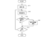
- FIG. 8 is a flowchart showing processing in the encoding processing unit of the third image processing apparatus.
- the complex region search unit 11 of the image performs a complex region search process of the image (S1).
- the output evaluation value is compared with the set threshold value (S2). If the evaluation value is smaller than the set threshold value, the reduced image encoding process (S3) is performed. If it is greater than or equal to the threshold value, the image encoding process (S4) is performed.
- the threshold value in the process of FIG. 8 corresponds to the first threshold value in the claims. The reduced image encoding process and the image encoding process will be described later.
- the encoding processing unit performs variable length encoding in the variable length encoding unit 20 using information on the result of the reduced image encoding process or the image encoding process (S5), and outputs an encoded stream. In this way, the entire operation of the encoding processing unit is performed.
- a motion vector is determined for each area where motion compensation is performed according to the complexity of the area. In order to improve the compression ratio as a whole, it is selected whether to reduce or not. Each process will be described later.
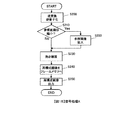
- FIG. 9 is a flowchart showing the complex region search process of an image.
- the image complex area search unit 11 divides the input image of one frame into, for example, areas of 16 pixels vertically and 16 pixels horizontally (S11). Then, the complex region search processing unit 11 of the image obtains an evaluation value for each divided region by using the frequency distribution after Fourier transform, the average value of the pixel values of the image, and the sum of absolute differences of the pixel values of each pixel. Calculate (S12).
- the complex region search unit 11 of the image compares the calculated evaluation value with the maximum value (maximum evaluation value) of the already calculated and stored evaluation values to determine whether the calculated evaluation value is the maximum. Is determined (S13). When it is the maximum, the maximum evaluation value is updated with the calculated evaluation value (S14).
- the complex region search unit 11 of the image determines whether or not the calculation of the evaluation value and the comparison with the maximum evaluation value are all finished for the region to be searched (S15). The process proceeds to step S12 to extract the next area and execute the same process. If the process has been completed for all areas in process S15, the complex area search for the image is terminated.
- the evaluation value stored as the maximum evaluation value at the end of the process becomes the evaluation value indicating the complexity of the image of each frame, and the process S2 shown in FIG. It is to be compared with the threshold value.
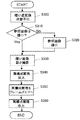
- FIGS. 10 and 11 are flowcharts showing the image encoding process shown in the process S4 of FIG.
- the image encoding process is performed when no reduction is performed in units of frames, and the processes shown in FIGS. 10 and 11 are continuously performed.
- the image region dividing unit 14 divides the frame image into regions of macro blocks (vertical 16 pixels ⁇ horizontal 16 pixels) (S21).
- the image region dividing unit 14 performs a flow for reducing the region image and a flow for not reducing in parallel in order to determine whether or not to reduce the motion vector. To do. Therefore, in FIG. 5, the image region dividing unit 14 outputs the divided region images to both the reduced image motion search unit 15 and the motion search unit 16.
- the motion search unit 16 checks whether or not the reference image is reduced (S22). In the case of Yes, the reference image is enlarged and acquired by the image enlargement unit 25 (S23). If the image is not reduced (No), the reference image is used as it is.
- the motion search unit 16 performs block matching using the reference image and the target image divided into regions, and extracts a region similar to the target image.
- a difference between the position of the extracted area and the area of the target image is detected as a motion vector (S24).
- an image based on a difference value of each pixel between the extracted area and the target image area is generated as a difference image.
- the size of the difference image is 16 pixels long ⁇ 16 pixels wide.
- the transform / quantization unit 17 performs transform quantization on the difference image, outputs the quantized transform coefficient (S25), and proceeds to processing (A).
- the reduced image motion search unit 15 inputs the area image that is not reduced from the image area dividing unit 14 and reduces the area image (S26). ). Then, the reduced image motion search unit 15 checks whether or not the reference area has been reduced (S27). If the reference region has not been reduced (No), the reduced image motion search unit 15 reduces the reference image via the image reduction unit 24. (S28). If the image is reduced (Yes), it is used as a reference image as it is.
- the reduced image motion search unit 15 extracts a region similar to the target image in the reference image as the reduced image motion search, and detects a difference between the position of the extracted region and the region of the target image as a reduced motion vector ( S29).
- a reduced motion vector S29
- an image based on a difference value of each pixel between the extracted area and the target image area is generated as a difference image.
- the size of the difference image is 8 pixels long ⁇ 8 pixels wide.
- the reduced image transform / quantization unit 18 performs transform quantization on the difference image, calculates a quantized transform coefficient, and proceeds to the processing (A). Thereby, with respect to an image that is not reduced in the entire frame, a conversion coefficient when the motion vector is not reduced and when the motion vector is reduced is calculated and output to the motion vector mode selection unit 19.
- the motion vector mode selection unit 19 selects an evaluation value (motion vector mode selection evaluation value for selecting a motion vector mode). ) To determine whether to select a reduced motion vector or a non-reduced motion vector.
- the motion vector mode selection unit 19 determines whether the number of quantized transform coefficients of the flow that does not reduce the region is the motion vector mode selection evaluation value, and is smaller than the threshold value (S31).
- the threshold value in the process S31 corresponds to the second threshold value in the claims.
- the motion vector mode selection unit 19 selects the no reduction mode (S32), and the transform / quantization unit 17 The quantized transform coefficient without reduction from is output (S33).
- the inverse transform / inverse quantization unit 21 performs inverse quantization / inverse transform using the output result of transform quantization (S34), and generates a reconstructed difference image (S35).
- the reconstructed image generation unit 22 generates a reconstructed image from the reconstructed difference image and the reference image generated by the image motion search unit 16 (S35), and the generated reconstructed image is stored in the frame memory. 23 (S36), and the process is terminated.
- the reconstructed image stored here is a reference image that is not reduced (vertical 16 pixels ⁇ horizontal 16 pixels).
- the motion vector mode selection unit 19 selects the reduction mode (S37), and the reduced image conversion / quantum
- the reduced quantized transform coefficient from the conversion unit 18 is output (S38).
- the reduced image inverse transform / inverse quantization is performed using the reduced quantized transform coefficient (S39), and the reconstructed image generation unit 22 generates a reconstructed image (S40) and enlarges it (S40).
- S41 the data is stored in the frame memory (S42), and the process is terminated.
- a reduced reference image (8 vertical pixels ⁇ 8 horizontal pixels) is obtained. In this way, the image encoding process is performed when the entire frame is not reduced.
- FIGS. 12 and 13 are flowcharts showing the reduced image encoding process shown in the process S3 of FIG.
- the reduced image encoding process is performed when reduction is performed in units of frames, and the processes shown in FIGS. 12 and 13 are continuously performed.
- the reduced image encoding process has the same basic flow as the image encoding process shown in FIGS. 10 and 11, and therefore only different parts will be described.
- the image reduction unit 12 reduces the input image in units of frames (S51).
- the reduced image region dividing unit 13 divides the reduced image into macroblocks (16 vertical pixels ⁇ 16 horizontal pixels) (S52), the flow that does not reduce the motion vector (does not reduce the region), and the motion vector
- the flow of reducing (reducing the area) is performed in parallel. That is, in FIG. 5, the reduced image region dividing unit 13 outputs the image of the divided region to both the reduced image motion search unit 15 and the motion search unit 16.
- the area of 16 pixels vertically ⁇ 16 pixels horizontally divided by the reduced image area dividing unit 13 corresponds to a 32 ⁇ 32 area in the original image before frame reduction.
- the motion search unit 16 checks whether or not the reference image has been reduced (S53). If the reference image has not been reduced (No), the image reduction unit 24 is checked. The reference image reduced to 16 pixels vertically ⁇ 16 pixels horizontally is acquired (S54). If the image has been reduced, the reference image is used as it is.
- the motion search unit 16 performs block matching using the reference image and the region-divided target image, extracts a region similar to the target image, and performs an image motion search that detects a difference between both positions as a motion vector.
- S55 A difference image is generated.
- the transform / quantization unit 17 performs transform quantization on the difference image, calculates a quantized transform coefficient (S56), and proceeds to processing (B).
- the reduced image motion search unit 15 reduces the input region image (S57).
- the target area for motion search is reduced in frame units, and the area is further reduced in size.
- the reduced image motion search unit 15 checks whether or not the reference image has been reduced (S58). If the reference image has been reduced, the image reduction unit 24 performs the reference image reduction A and then acquires the reference image ( S59), the process proceeds to process 61.
- the reference image reduction A is a process of reducing the vertical and horizontal directions to 1 ⁇ 2. If it is determined in step S58 that the reference image has not been reduced, the image reduction unit 24 performs reference image reduction B, and the process proceeds to step 61.
- Reference image reduction B is a process of reducing the vertical and horizontal dimensions to 1/4.
- the reduced image motion search unit 15 compares the target image having the same size with the reference image, performs block matching, extracts a region similar to the target image from the reference image, and detects a reduced motion vector.
- a reduced image motion search is performed (S61), and an image based on a difference value between each pixel in the extracted area and the target image area is generated as a difference image.
- the reduced image transform / quantization unit 18 performs transform quantization on the difference image, calculates a quantized transform coefficient (S62), and proceeds to the process (B).
- the motion vector mode selection unit 19 calculates a motion vector mode selection evaluation value. Compared with the threshold value (S63), if the motion vector mode selection evaluation value is equal to or greater than the threshold value (in the case of No), the no reduction mode is selected (S64) and is less than the threshold value. If yes (Yes), the reduction mode is selected (S70).
- the reference image obtained by the reduced image encoding process is a reduced reference image.
- the encoding processing unit determines whether or not the entire frame has been reduced according to the complexity of the image in units of frames, and each of the cases when the entire frame is reduced and not moved Depending on the complexity of the macroblock that is the unit of compensation, it is determined whether to reduce the motion vector, that is, the macroblock, and perform appropriate coding for each region to reduce the output image. It is possible to improve the compression rate while suppressing.
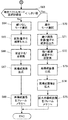
- FIG. 14 is a flowchart illustrating an outline of processing in the decoding processing unit of the third image processing apparatus.
- the decoding processing unit first, the stream to which the variable length decoding unit 31 is input is subjected to variable length decoding (S100), and the image size determination unit 32 receives the frame input from the header information or the like. To determine whether or not the frame is reduced (S110).
- the motion vector mode determination unit 34 determines whether or not the motion vector is reduced (S120), and when the motion vector is not reduced. In the case of No, the decryption processing unit proceeds to decryption process A (S130). If the motion vector is reduced (Yes) in process S120, the decoding processing unit proceeds to decoding process B (S140).
- the motion vector mode determination unit 34 determines whether or not the motion vector is reduced (S150). ), The decryption processing unit proceeds to decryption process C (S160). In the process 150, when the motion vector is reduced (Yes), the decoding processing unit proceeds to the decoding process D (S170). That is, in the decoding processing unit of the third image processing apparatus, four types of decoding processing are performed according to the presence or absence of frame-based reduction and the presence or absence of motion vector reduction.
- FIG. 15 is a flowchart of the decoding process A shown in the process S130 of FIG.
- the decoding process A is a decoding process of an area where the entire frame is not reduced and the motion vector is not reduced.
- the inverse transform / inverse quantization unit 33 performs an inverse transform / inverse quantization process to generate a reconstructed difference image (S200). Then, the motion compensation unit 35 determines whether or not the reference image to be referred to for inter-screen prediction is reduced (S210). If the reference image is reduced (in the case of Yes), the reference image enlargement / reduction unit 39 enlarges the reference image (S220). If the image is not reduced (No), the reference image is used as it is.
- the motion compensation unit 35 performs a motion compensation process using the corresponding region of the reference image using the unreduced motion vector extracted by the variable length decoding unit 31 (S230), A reconstructed image is generated based on the pixel sum.
- the reconstructed image is stored in the frame memory 38 as a reference image (S240), and finally the reconstructed image is output (S250).
- a reference image that is not reduced is obtained. In this way, the decoding process A is performed.
- FIG. 16 is a flowchart of the decoding process B shown in the process S140 of FIG.
- the decoding process B is a decoding process of an area in which the entire frame is not reduced and the motion vector is reduced.
- the inverse transform / inverse quantization unit 33 performs reduced inverse transform / inverse quantization to generate a difference image of the reduced area (S300). Specifically, in the reduced inverse transform / inverse quantization, the part of the region A in FIG. 7 is extracted from the transform coefficient of 8 vertical pixels ⁇ 8 horizontal pixels, and the inverse transform and inverse quantization of 4 vertical pixels ⁇ 4 horizontal pixels are performed. To implement. As a result, a reconstructed difference image that has been reduced (for example, vertical 8 pixels ⁇ horizontal 8 pixels) is generated.
- the motion compensation unit 35 determines whether or not the reference image is reduced (S310). If the reference image is not reduced (No), the reference image enlargement / reduction unit 39 reduces the reference image (S320). ). If the image has been reduced (if Yes), the reference image is used as it is. Then, the motion compensation unit 35 uses the reduced motion vector extracted from the variable length decoding unit 31 and performs a reduced image motion compensation process for performing motion compensation on the reduced image using the corresponding region of the reference image (S330). ), A reconstructed image is generated by pixel sum with the reconstructed difference image.
- the reconstructed image enlargement unit 37 enlarges the reconstructed image (S340) and stores it in the frame memory (S350). Thereby, a reference image that is not reduced is obtained.
- the motion compensation unit 35 outputs the reconstructed image to the image enlargement unit 36, and the image enlargement unit 36 enlarges the reconstructed image to the original size and outputs the enlarged reconstructed image (S360). In this way, the decoding process B is performed.
- FIG. 17 is a flowchart of the decoding process C shown in the process S160 of FIG.
- the decoding process C is a decoding process of an area where the entire frame is reduced and the motion vector is not reduced.
- the inverse transform / inverse quantization unit 33 performs an inverse transform / inverse quantization process to generate a reconstructed difference image (S400). Then, the motion compensation unit 35 determines whether or not the reference image referred to for inter-screen prediction has been reduced (S410). If the reference image has not been reduced (No), the reference image enlargement / reduction unit 39 reduces the reference image (S420). If the image has been reduced (if Yes), the reference image is used as it is.
- the motion compensation unit 35 performs a motion compensation process using the corresponding region of the reference image using the unreduced motion vector extracted by the variable length decoding unit 31 (S430), and reconstructed difference image A reconstructed image is generated with the pixel sum.
- the decoding process C is performed.
- FIG. 18 is a flowchart of the decoding process B shown in the process S170 of FIG.
- the decoding process D is a decoding process for an area in which the entire frame is reduced and the motion vector is reduced.
- the inverse transform / inverse quantization unit 33 performs reduced inverse transform / inverse quantization to generate a difference image of the reduced region (S500).
- the reduced inverse transform / inverse quantization performs inverse transform and inverse quantization of vertical 4 pixels ⁇ horizontal 4 pixels from coefficients of vertical 8 pixels ⁇ horizontal 8 pixels, as in the decoding process B of FIG.
- a reconstructed difference image reduced to, for example, 8 vertical pixels ⁇ 8 horizontal pixels is generated.
- the motion compensation unit 35 determines whether or not the reference image has been reduced (S510). If the reference image has been reduced (Yes), the reference image enlargement / reduction unit 39 performs the reference image reduction process A. Thus, the reference image is reduced (S520).
- the reference image reduction process A is a process for reducing the vertical and horizontal halves.
- the reference image enlargement / reduction unit 39 reduces the reference image by the reference image reduction processing B (S530).
- the reference image reduction process B is a process for reducing the image to 1/4 in the vertical and horizontal directions.
- the motion compensation unit 35 performs a reduced image motion compensation process using the corresponding region of the reference image using the reduced motion vector extracted by the variable length decoding unit 31 (S540), A reconstructed image is generated with the pixel sum of.
- the reconstructed image enlargement unit 37 enlarges the reconstructed image (S550) and stores it in the frame memory (S560).
- the motion compensation unit 35 outputs the reconstructed image to the image enlargement unit 36, and the image enlargement unit 36 enlarges the reconstructed image to the original size and outputs the enlarged reconstructed image (S570). In this way, the decoding process D is performed.
- FIG. 19 is an explanatory diagram illustrating an example of an image size processed by the third image processing apparatus.
- FIG. 19 shows how the image size changes depending on the combination of whether or not the entire frame is reduced and whether or not the motion vector is reduced in the processing in the encoding processing unit.
- the macroblock (MB) size is the size of an area divided by the image area dividing unit 14 or the reduced image area dividing unit 13, and in either case, the vertical 16 pixels ⁇ horizontal 16 pixels It has become.
- the size at the time of MC indicates the size of an area when the motion search unit 16 or the reduced motion search unit 15 performs a motion search process such as block matching.
- MC Motion Compensation
- the reduced image motion search unit 15 processes the input macroblock after reducing the size of the input macroblock to 8 pixels ⁇ 8 pixels.
- the size of the original image is the original size of the macroblock, which is the same as the macroblock size when the frame is not reduced (vertical 16 pixels ⁇ horizontal 16 pixels), and when the frame is reduced, It becomes 32 vertical pixels x 32 horizontal pixels.
- the reconstructed difference image is the size of the image reconstructed by the reconstructed image generation unit 22, and when motion vector reduction is performed, the vertical 8 pixels ⁇ horizontal 8 pixels regardless of the presence or absence of frame reduction. It becomes.
- the size of the reference image stored in the frame memory and the size of the reference image at the time of reading when the read reference image is not reduced in the reduced image motion search unit 15 or the motion search unit 16 are described. It shows.
- the size of the reference image stored in the frame memory and the reference at the time of reading are read. It shows the size of the image.
- the motion vector is read after being enlarged / reduced to 16 pixels ⁇ 16 pixels, and if the motion vector is reduced, it is 8 pixels vertically. ⁇ Reduced to 8 horizontal pixels and read.
- the encoding processing unit calculates an evaluation value of complexity for each frame, and if the evaluation value is less than the first threshold value, If the value is equal to or greater than the threshold value, the entire frame is not reduced. Further, the reduced or unreduced frame is divided into regions of a predetermined size, and a motion vector indicating the complexity of the region A mode selection evaluation value is calculated, and if the motion vector mode selection evaluation value is less than the second threshold value, the motion vector is reduced.
- the decoding processing unit appropriately selects from four types of decoding processing for each region according to the combination of the presence / absence of the entire frame reduction and the presence / absence of the reduction of the motion vector. Select the appropriate process Therefore, for complex areas of the image, transmission is performed without reducing the amount of information to prevent image quality degradation, and for uncomplicated areas of the image, the entire frame and motion vectors are reduced. The amount of header information can be greatly reduced, and the compression rate can be improved by performing appropriate encoding / decoding for each region. In particular, there is an effect that the image can be efficiently encoded in an image in which the complexity of the image varies with time.
- the present invention is suitable for an image processing apparatus capable of reproducing a high-quality image on the receiving side even when transmitted in a low band, and further suitable for an image processing apparatus capable of improving the compression rate in encoding. ing.
- variable length decoding unit 32 ... image size determination unit, 33 ... inverse transform / inverse quantization unit, 34. .. Motion vector mode determination unit, 35 ... Motion compensation unit, 36 ... Image enlargement unit, 37 ... Reconstructed image enlargement unit, 39 ... Reference image enlargement / reduction unit, 202 ... Image reduction unit, 203, 218 ... Complexity calculation unit, 204 ... Multiplexer, 211, 311 ... Control unit, 215, 304 ... Demultiplexer, 216, 316 ... Decoding Conversion unit, 217, 317 ... image enlargement unit, 219 ... complexity comparison unit, 220, 320 ... parameter calculation unit, 303, 319 ... complexity table processing unit
Abstract
Provided is an image processing device which can reproduce a high-quality image on the receiving side even when transmitted at a low bandwidth. This image processing device performs scaling and applies super-resolution in accordance with the complexity of the image. On the compression side, a complexity calculation unit (203) calculates the transmission image complexity, which indicates the complexity of the input image, multiplexes and outputs the transmission image complexity to an encoded stream which is from an encoding unit (212), and a control unit (211) configures the cutoff frequency of a low pass filter (201) and the scaling coefficient of an image reduction unit (202) in accordance with the transmission image complexity. On the expansion side, a complexity calculation unit (218) calculates the decoded image complexity indicating the complexity of a decoded and expanded image, a complexity comparison unit (219) compares the transmission image complexity and the decoded image complexity and outputs the difference or ratio, and, on the basis of the difference or ratio, a parameter calculation unit (220) optimizes and configures the scaling coefficient of an image enlargement unit (216) and the folding frequency of a super-resolution processing unit (221).
Description
本発明は、画像処理装置及び動画像伝送方法に係り、特に、低帯域で伝送した場合でも受信側で高画質の画像を再生することができる画像処理装置等に関する。
The present invention relates to an image processing apparatus and a moving image transmission method, and more particularly to an image processing apparatus and the like that can reproduce a high-quality image on the receiving side even when transmitted in a low band.
近年、画像を伝送するためのデータ量は日々増加している。2011年に切替わった地上デジタルテレビ放送の影響もあり、一般的に使用される画像の解像度はこれまでのアナログ解像度(720pix×480pix)からFull HD(High-Definition)解像度(1920pix×1080pix)へ変化している。
In recent years, the amount of data for transmitting images has been increasing day by day. Due to the influence of digital terrestrial television broadcasting that was switched in 2011, the resolution of commonly used images has been changed from the conventional analog resolution (720 pix x 480 pix) to Full HD (High-Definition) resolution (1920 pix x 1080 pix). It has changed.
また、駅や空港、ビルや河川といった様々なロケーションで使用される監視用のカメラにおいても、CCDやCMOSセンサの高精細化が進み、解像度は従来のアナログ解像度から飛躍的に向上している。
Also, in surveillance cameras used in various locations such as stations, airports, buildings, and rivers, the resolution of CCD and CMOS sensors is increasing, and the resolution is dramatically improved from the conventional analog resolution.
これにより、高画質な画像を撮影・伝送できるようになった反面、必要となる伝送帯域は増加する。Full HDの画像を非圧縮で伝送しようとした場合、約1.5Gbpsの伝送帯域が必要である。パケット交換ネットワークを介して伝送しようとした場合、現在家庭用ブロードバンドとして普及している光ファイバであっても、100Mbps程度であり、非圧縮で伝送することはできない。
As a result, high-quality images can be taken and transmitted, but the required transmission bandwidth increases. When trying to transmit Full HD images without compression, a transmission bandwidth of about 1.5 Gbps is required. When trying to transmit through a packet switching network, even an optical fiber that is currently popular as home broadband is about 100 Mbps and cannot be transmitted uncompressed.
そのため、伝送可能な帯域までデータを圧縮する必要がある。現在、高効率の圧縮技術の規格としてH.264やH.265がある。これらは、動画像符号化の国際標準規格である。
Therefore, it is necessary to compress the data to a transmittable band. Currently, there are H.264 and H.265 as standards for highly efficient compression technology. These are international standards for moving picture coding.
圧縮技術においては、伝送帯域と画質はトレードオフの関係にあり、低帯域で伝送するために高圧縮をした場合、画質劣化が生じてしまう。そこで、低帯域で伝送しても、高画質の画像を得ることが求められており、デジタル画像処理により高解像度化を図る超解像技術が注目されている。
In compression technology, transmission bandwidth and image quality are in a trade-off relationship, and image quality degradation occurs when high compression is performed for transmission in a low bandwidth. Therefore, it is demanded to obtain a high-quality image even if it is transmitted in a low band, and super-resolution technology for increasing the resolution by digital image processing has attracted attention.
図20は、一般的な画像処理装置を有する画像伝送システムの概略構成図である。図20に示すように、画像伝送システムでは、送信側の構成としてビデオエンコーダ1を備え、受信側の構成としてビデオデコーダ2と、超解像処理部3とを備えている。
FIG. 20 is a schematic configuration diagram of an image transmission system having a general image processing apparatus. As shown in FIG. 20, the image transmission system includes a video encoder 1 as a configuration on the transmission side, and a video decoder 2 and a super-resolution processing unit 3 as a configuration on the reception side.
尚、図20の例では、送信側の画像処理装置では送信に用いられる構成のみを示し、受信側の画像処理装置では受信に用いられる構成のみを示している。
In the example of FIG. 20, only the configuration used for transmission is shown in the image processing apparatus on the transmission side, and only the configuration used for reception is shown in the image processing apparatus on the reception side.
送信側のビデオエンコーダ1は、CCDカメラ等の画像入力装置から入力された画像を、例えばH.264等の符号化方式で符号化し、IPネットワークや同軸ケーブル網等の伝送路に出力する。
The video encoder 1 on the transmission side encodes an image input from an image input device such as a CCD camera using an encoding method such as H.264, and outputs it to a transmission path such as an IP network or a coaxial cable network.
受信側のビデオデコーダ2は、伝送路を介して受信した画像データを、ビデオエンコーダ1における符号化方式に対応した方式で復号化する。
The video decoder 2 on the receiving side decodes the image data received via the transmission path by a method corresponding to the encoding method in the video encoder 1.
超解像処理部3は、復号画像から、より高解像の画像を得る超解像処理を行って、出力画像とする。
The super-resolution processing unit 3 performs super-resolution processing for obtaining a higher-resolution image from the decoded image and sets it as an output image.
ところで、H.264やH.265の符号化方式では、様々な符号化ツールが規定されており、伝送帯域に合わせて柔軟な調整を行うことで画質の高品質化を図ることが可能である。そして、ビデオデコーダ側で、画質劣化の少ない画像に対して超解像処理を行うことにより、高画質化が可能となる。
By the way, in the H.264 and H.265 encoding methods, various encoding tools are defined, and it is possible to improve the image quality by performing flexible adjustment according to the transmission band. . Then, by performing super-resolution processing on an image with little image quality degradation on the video decoder side, it is possible to improve the image quality.
しかし、例えば、ビットレートと画像サイズのみしか指定できないようなエンコーダを使用しなければならない場合には、圧縮処理の細かい調整ができないため、画質劣化が生じてしまう。そのため、デコーダ側において超解像処理を施しても効果が期待できない。
However, for example, when it is necessary to use an encoder that can specify only the bit rate and the image size, fine adjustment of the compression processing cannot be performed, so that the image quality is deteriorated. Therefore, no effect can be expected even if super-resolution processing is performed on the decoder side.
[動画像データの符号化における圧縮]
ここで、動画像の符号化における圧縮率の向上について説明する。動画像符号化方法は、MPEG(Moving Picture Experts Group)に代表される動画像符号化装置が開発され、実用に供されている。更に、圧縮効率を向上させるため、例えば、画面内予測および画面間予測を用い、予測値と画素値の差分値を用いることにより、次段の直交変換、量子化処理及び可変長符号化処理の効率を向上させる技術が提案されている(例えば非特許文献1参照)。 [Compression in encoding moving image data]
Here, the improvement of the compression rate in the encoding of moving images will be described. As a moving picture coding method, a moving picture coding apparatus represented by MPEG (Moving Picture Experts Group) has been developed and put into practical use. Furthermore, in order to improve the compression efficiency, for example, intra prediction and inter prediction are used, and by using the difference value between the prediction value and the pixel value, the orthogonal transformation, quantization processing, and variable length encoding processing of the next stage are performed. A technique for improving the efficiency has been proposed (see, for example, Non-Patent Document 1).
動画像符号化で扱う情報は、画面を構成する画素そのものを扱う情報(動画像情報)と、動画像情報をどのように扱うかを記載する情報(ヘッダ情報)、及び画面間予測に用いる動きベクトル情報の組合せで構成される。
The information handled by the moving image coding includes information (moving image information) that handles the pixels themselves constituting the screen, information (header information) that describes how to handle the moving image information, and motion used for inter-screen prediction. It consists of a combination of vector information.
近年の技術進歩により、動画像情報の圧縮効率は目覚ましい向上を見せているが、ヘッダ情報及び動きベクトル情報に関しては圧縮率の向上はそれほど高くはない。
Although recent technological advances have shown remarkable improvement in the compression efficiency of moving picture information, the improvement in compression rate is not so high for header information and motion vector information.
尚、画像伝送装置に関する関連技術としては、国際公開第2010/137323号「映像符号化装置、映像復号装置、映像符号化方法、および映像復号方法」(三菱電機株式会社、特許文献1)明細書、特許第4245576号公報「画像圧縮伸張法、画像圧縮装置及び画像伸張装置」(ティーオーエー株式会社、特許文献2)、Joint Video Team (JV T) of ISO / IEC MPEG & ITU-T VCEG : Text of ISO / IEC 14496-10Advanced Video Cod ing 3rd Edition (2004)(非特許文献1)がある。
In addition, as related technology regarding the image transmission apparatus, International Publication No. 2010/137323 “Video Coding Device, Video Decoding Device, Video Coding Method, and Video Decoding Method” (Mitsubishi Electric Corporation, Patent Document 1) specification , Japanese Patent No. 4245576, “Image Compression / Expansion Method, Image Compression Device and Image Expansion Device” (TEO Corporation, Patent Document 2), Joint Video Team (JV®T) of ISO // IEC MPEG / & ITU-T VCEG: Text of ISO ISO / IEC 14496-10 Advanced Video Coding 3rd Edition (2004) (Non-patent Document 1).
特許文献1には、映像符号化装置の圧縮部で、予測誤差信号を縮小変換してから変換・量子化するか否かを選択して、量子化係数データを生成し、縮小した場合には、量子化係数データを逆量子化・逆変換した後、拡大変換して復号予測誤差信号を生成することが記載されている。
In Patent Document 1, when the compression unit of the video encoding device performs conversion conversion and quantization after reducing and converting the prediction error signal, the quantization coefficient data is generated and reduced. In addition, it is described that the quantized coefficient data is inversely quantized and inversely transformed, and then subjected to expansion transformation to generate a decoded prediction error signal.
特許文献2には、画像圧縮伸張法において、重要領域として指定された領域以外の領域は縮小データに変換し、重要領域の水平幅に合わせた画像領域内に重要領域及び縮小データを再配置して縮小画像データを生成し、動き補償予測、符号化処理を行い、復元時には、伸張処理された後、ヘッダ情報に基づいて元の配置を復元し、縮小データについては補間処理を行って、画像データを復元することが記載されている。
In Patent Document 2, in an image compression / decompression method, an area other than an area designated as an important area is converted into reduced data, and the important area and the reduced data are rearranged in an image area that matches the horizontal width of the important area. Reduced image data is generated, motion compensation prediction and encoding processing are performed, and at the time of restoration, after decompression processing, the original arrangement is restored based on the header information, and the reduced data is subjected to interpolation processing to obtain an image It describes restoring data.
上述したように、従来の画像処理装置では、伝送帯域に合わせて柔軟に調整を行って符号化・復号化を行うものであるから、狭い伝送帯域を使って映像を高精細のまま伝送しようとすると、ビデオエンコーダにおいて圧縮処理の細かい調整ができず、出力画像の画質が復元困難なほどに劣化してしまうという問題点があった。
As described above, in the conventional image processing apparatus, encoding and decoding are performed by adjusting flexibly according to the transmission band. Therefore, an attempt is made to transmit video with high definition using a narrow transmission band. As a result, the video encoder cannot finely adjust the compression process, and the image quality of the output image is deteriorated so as to be difficult to restore.
尚、特許文献1及び特許文献2には、圧縮側において、入力画像の複雑さを送信側複雑度として算出し、当該送信側複雑度に応じてローパスフィルタのカットオフ周波数と縮小部のスケーリング係数を調整して符号化し、符号化ストリームと送信側複雑度とを送信し、伸張側において、復号画像の複雑さと受信した送信画像の複雑さとを比較して、両者の差が最小となるように、画像拡大部のスケーリング係数と超解像処理部の折り返し周波数を最適化して設定することは記載されていない。
In Patent Document 1 and Patent Document 2, on the compression side, the complexity of the input image is calculated as the transmission-side complexity, and the cut-off frequency of the low-pass filter and the scaling factor of the reduction unit are calculated according to the transmission-side complexity. The encoded stream and the transmission-side complexity are transmitted, and the decompression side compares the complexity of the decoded image with the complexity of the received transmission image so that the difference between the two is minimized. In addition, there is no description of optimizing and setting the scaling coefficient of the image enlargement unit and the folding frequency of the super-resolution processing unit.
本発明は上記実状に鑑みて為されたもので、従来のビデオエンコーダでは細かい調整ができない状況でも、高画質の画像を得ることができる画像処理装置を提供することを目的とする。
The present invention has been made in view of the above circumstances, and an object thereof is to provide an image processing apparatus capable of obtaining a high-quality image even in a situation where fine adjustment cannot be performed by a conventional video encoder.
本発明の一側面では、入力された画像を圧縮する画像圧縮部と、圧縮された画像を伸張して出力する画像伸張部とを備えた画像処理装置であって、画像圧縮部が、入力された画像信号を、設定されたカットオフ周波数で帯域制限するローパスフィルタと、ローパスフィルタからの出力信号を、設定された縮小係数に従って縮小する画像縮小部と、帯域制限され縮小された画像信号を符号化する符号化部と、入力された画像信号について画像の複雑さを示す第1のパラメータを算出する第1の複雑さ算出部と、前記第1のパラメータに基づいて、最適なカットオフ周波数をローパスフィルタに設定すると共に、最適な縮小係数を前記画像縮小部に設定する第1の制御部と、第1のパラメータを、符号化部から出力された符号化ストリームに多重化して出力するマルチプレクサとを備え、画像伸張部が、入力された信号から符号化ストリームと第1のパラメータとを抽出するデマルチプレクサと、符号化ストリームを復号化する復号化部と、復号化部からの出力信号を指定された拡大係数に従って拡大する画像拡大部と、拡大された画像について、指定された折り返し周波数を用いて超解像処理を施す超解像処理部と、拡大された画像について、画像の複雑さを示す第2のパラメータを算出する第2の複雑さ算出部と、第1のパラメータと第2のパラメータとの差又は比を算出する複雑さ比較部と、当該差又は比に基づいて、最適な拡大係数を画像拡大部に設定すると共に、最適な折り返し周波数を超解像処理部に設定するパラメータ算出部とを備えたことを特徴としている。
In one aspect of the present invention, an image processing apparatus includes an image compression unit that compresses an input image, and an image expansion unit that decompresses and outputs the compressed image. A low-pass filter that limits the band of the received image signal at a set cutoff frequency, an image reduction unit that reduces the output signal from the low-pass filter according to a set reduction factor, and a band-limited and reduced image signal. An encoding unit, a first complexity calculation unit that calculates a first parameter indicating the complexity of the image for the input image signal, and an optimal cutoff frequency based on the first parameter. A first control unit that sets an optimal reduction coefficient in the image reduction unit and a first parameter in the encoded stream output from the encoding unit are set in the low-pass filter. A demultiplexer that extracts the encoded stream and the first parameter from the input signal, a decoding unit that decodes the encoded stream, and a decoding unit An image enlarging unit for enlarging an output signal from the image according to a specified enlarging factor, a super-resolution processing unit that performs super-resolution processing on the enlarged image using a specified aliasing frequency, and an enlarged image A second complexity calculation unit that calculates a second parameter indicating the complexity of the image, a complexity comparison unit that calculates a difference or ratio between the first parameter and the second parameter, and the difference or ratio And a parameter calculation unit that sets an optimum enlargement coefficient in the image enlargement unit and sets an optimum aliasing frequency in the super-resolution processing unit.
また、本発明の他の側面では、入力された画像を圧縮する画像圧縮部と、圧縮された画像を伸張して出力する画像伸張部とを備えた画像処理装置であって、画像圧縮部が、入力された画像信号を、設定されたカットオフ周波数で帯域制限するローパスフィルタと、ローパスフィルタからの出力信号を、設定された縮小係数に従って縮小する画像縮小部と、帯域制限され縮小された画像信号を符号化する符号化部と、符号化部から出力された信号から、情報損失の程度を示す量子化パラメータを抽出するデマルチプレクサと、複雑さを示すパラメータと量子化パラメータとの組み合わせに対応するフィードバック値を記憶するテーブルを備え、入力された画像信号について画像の複雑さを示す第1のパラメータを算出し、テーブルに基づいて第1のパラメータと抽出された量子化パラメータとに対応するフィードバック値を出力する第1の複雑さテーブル処理部と、フィードバック値に基づいて、最適なカットオフ周波数をローパスフィルタに設定すると共に、最適な縮小係数を画像縮小部に設定する制御部とを備え、画像伸張部が、入力された信号から符号化ストリームと量子化パラメータとを抽出するデマルチプレクサと、符号化ストリームを復号化する復号化部と、復号化部からの出力信号を、設定された拡大係数に従って拡大する画像拡大部と、指定された折り返し周波数を用いて超解像処理を施す超解像処理部と、複雑さを示すパラメータと量子化パラメータとの組み合わせに対応する拡大係数を記憶するテーブルを備え、画像拡大部で拡大された画像について画像の複雑さを示す第2のパラメータを算出し、テーブルに基づいて第2のパラメータと抽出された量子化パラメータとに対応する拡大係数を出力する第2の複雑さテーブル処理部と、拡大係数を画像拡大部に設定すると共に、拡大係数に基づいて最適な折り返し周波数を超解像処理部に設定するパラメータ算出部とを備えたことを特徴としている。
According to another aspect of the present invention, there is provided an image processing apparatus including an image compression unit that compresses an input image, and an image expansion unit that decompresses and outputs the compressed image. A low-pass filter that band-limits the input image signal at a set cutoff frequency, an image reduction unit that reduces an output signal from the low-pass filter according to a set reduction factor, and a band-limited reduced image Corresponds to the combination of the encoder that encodes the signal, the demultiplexer that extracts the quantization parameter that indicates the degree of information loss from the signal output from the encoder, and the parameter that indicates the complexity and the quantization parameter A first parameter indicating the complexity of the image for the input image signal, and a table for storing the feedback value A first complexity table processing unit that outputs a feedback value corresponding to one parameter and the extracted quantization parameter; and an optimum cutoff frequency is set in the low-pass filter based on the feedback value, and an optimum A demultiplexer for extracting the encoded stream and the quantization parameter from the input signal, and a decoding unit for decoding the encoded stream. An image enlarging unit for enlarging the output signal from the decoding unit according to a set enlarging coefficient, a super-resolution processing unit for performing super-resolution processing using a specified aliasing frequency, and a parameter indicating complexity And a table for storing enlargement coefficients corresponding to the combination of the quantization parameter and the image enlarged by the image enlargement unit. A second complexity table processing unit that calculates a second parameter indicating the length and outputs an expansion coefficient corresponding to the second parameter and the extracted quantization parameter based on the table; And a parameter calculation unit that sets an optimal aliasing frequency in the super-resolution processing unit based on the enlargement coefficient.
また、本発明の他の側面では、上記画像処理装置において、画像圧縮部において、画像拡大部が、第1のパラメータが予め設定された第1のしきい値未満であれば、フレーム全体での縮小を行い、前記第1のしきい値以上であれば、フレーム全体での縮小を行わず、符号化部が、フレーム全体の縮小の有無にかかわらず、入力された画像を分割した領域のそれぞれについて複雑さを示すパラメータを算出し、パラメータが予め設定された第2のしきい値未満であれば、当該領域を縮小して符号化し、パラメータが前記第2のしきい値以上であれば、当該領域を縮小せずに符号化し、画像伸張部において、復号化部が、画像圧縮部でのフレーム全体の縮小の有無及び領域毎の縮小の有無に応じて領域毎に復号化を行うことを特徴としている。
According to another aspect of the present invention, in the image processing apparatus, in the image compression unit, if the image enlargement unit is less than the first threshold set in advance, the entire frame If the image is reduced and if it is equal to or greater than the first threshold value, the entire frame is not reduced, and each of the regions obtained by dividing the input image by the encoding unit regardless of whether the entire frame is reduced or not. If the parameter is less than a preset second threshold value and the parameter is less than a preset second threshold value, the region is reduced and encoded.If the parameter is equal to or greater than the second threshold value, The image is encoded without being reduced, and in the image expansion unit, the decoding unit performs decoding for each region depending on whether or not the entire frame is reduced in the image compression unit and whether or not each region is reduced. It is a feature.
本発明によれば、伝送帯域に応じてきめ細かな設定ができない場合であっても、画像圧縮部と画像伸張部とが画像の複雑さに応じて連携して、最適な縮小/拡大処理及び超解像処理を行うことができ、低帯域で伝送しても高画質の出力画像を再生することができる。
According to the present invention, even when fine settings cannot be made according to the transmission band, the image compression unit and the image expansion unit cooperate with each other according to the complexity of the image, so that an optimal reduction / enlargement process and super Resolution processing can be performed, and a high-quality output image can be reproduced even when transmitted in a low band.
或いは、本発明によれば、伝送帯域に応じてきめ細かな設定ができない場合であっても、画像圧縮部からパラメータを送信することなく、画像の複雑さに応じて最適な縮小/拡大処理及び超解像処理を行うことができ、低帯域で伝送しても高画質の出力画像を再生することができる。
Alternatively, according to the present invention, even when detailed settings cannot be made according to the transmission band, the optimum reduction / enlargement processing and superimposition according to the complexity of the image can be performed without transmitting parameters from the image compression unit. Resolution processing can be performed, and a high-quality output image can be reproduced even when transmitted in a low band.
或いは、本発明によれば、画像の複雑さに応じて、フレーム全体の縮小と、動きベクトルの縮小とを組み合わせて行うことにより、ヘッダの情報量を削減でき、動画像の圧縮率を向上させることができる効果がある。
Alternatively, according to the present invention, the amount of header information can be reduced and the compression rate of moving images can be improved by combining the reduction of the entire frame and the reduction of the motion vector in accordance with the complexity of the image. There is an effect that can.
本発明の実施の形態に係る画像処理装置及び画像処理方法は、要約すると、送信側装置において、入力画像に対して画像の複雑度を計算し、計算結果(送信画像複雑度)を圧縮画像ストリームに多重して受信側装置へ送信すると共に、送信画像複雑度に応じて、ローパスフィルタの通過帯域及び画像圧縮処理におけるスケーリングパラメータを適切に設定する。また受信側装置において、受信した送信画像複雑度と、復号された画像について計算した複雑度(復号画像複雑度)とを比較して、その比較結果に基づいて画像伸張処理のスケーリングパラメータ及び超解像処理の折返し周波数のパラメータを最適化する。このように送受信側の画像処理装置が連携動作を行って、画像の複雑度に応じて適切なスケーリング処理及び超解像処理を行うことができ、高画質の出力画像を得る。
In summary, the image processing apparatus and the image processing method according to the embodiment of the present invention calculate the image complexity for the input image in the transmission side apparatus, and the calculation result (transmission image complexity) is compressed into the compressed image stream. Are multiplexed and transmitted to the receiving apparatus, and the pass band of the low-pass filter and the scaling parameter in the image compression processing are appropriately set according to the transmission image complexity. Further, the receiving side apparatus compares the received transmission image complexity with the complexity calculated for the decoded image (decoded image complexity), and based on the comparison result, the scaling parameter and super solution of the image expansion processing are compared. Optimize the aliasing frequency parameters for image processing. As described above, the image processing apparatus on the transmission / reception side performs a cooperative operation, and can perform appropriate scaling processing and super-resolution processing according to the complexity of the image, thereby obtaining a high-quality output image.
また、本発明の実施の形態に係る画像処理装置は、送信側装置において、画像の複雑度を計算し、圧縮画像ストリームから符号化処理の量子化パラメータを抽出し、複雑度と量子化パラメータに応じて、ローパスフィルタの通過帯域及び画像圧縮処理におけるスケーリングパラメータを適切に設定し、受信側装置において、受信信号から量子化パラメータを抽出し、当該量子化パラメータに応じて画像伸張処理のスケーリングパラメータ及び超解像処理のパラメータを最適化するものであり、送受信側の画像処理装置が連携動作を行って、画像の複雑度に応じて適切なスケーリング処理及び超解像処理を行うことができ、高画質の出力画像を得ることができるものである。
Also, the image processing apparatus according to the embodiment of the present invention calculates the complexity of the image in the transmission side apparatus, extracts the quantization parameter of the encoding process from the compressed image stream, and uses the complexity and the quantization parameter. Accordingly, the pass band of the low-pass filter and the scaling parameter in the image compression process are appropriately set, and the reception side apparatus extracts the quantization parameter from the received signal, and the scaling parameter for the image expansion process according to the quantization parameter and It optimizes the parameters of super-resolution processing, and the image processing device on the transmission / reception side can perform cooperative operations to perform appropriate scaling processing and super-resolution processing according to the complexity of the image. An output image with high image quality can be obtained.
図1は、本発明の実施例1に係る画像処理装置の構成ブロック図である。
FIG. 1 is a block diagram showing the configuration of an image processing apparatus according to Embodiment 1 of the present invention.
実施例1に係る画像処理装置(第1の画像処理装置)は、ビデオエンコーダ1、ビデオデコーダ2及び超解像処理部3からなる図20に示した画像処理システムと似た構成を有する。つまり、図1の上側が図20のビデオエンコーダ1に相当し、下側が図20のビデオデコーダ2と超解像処理部3に相当している。ビデオデコーダは、超解像処理部を含む構成となっている。尚、ビデオエンコーダは請求項に記載した画像圧縮部に相当し、ビデオデコーダは画像伸張部に相当している。
The image processing apparatus (first image processing apparatus) according to the first embodiment has a configuration similar to that of the image processing system illustrated in FIG. 20 including the video encoder 1, the video decoder 2, and the super-resolution processing unit 3. That is, the upper side in FIG. 1 corresponds to the video encoder 1 in FIG. 20, and the lower side corresponds to the video decoder 2 and the super-resolution processing unit 3 in FIG. The video decoder includes a super-resolution processing unit. The video encoder corresponds to the image compression unit described in the claims, and the video decoder corresponds to the image expansion unit.
そして、ビデオエンコーダは、画像入力IF部200と、ローパスフィルタ201と、画像縮小部202と、符号化部212と、複雑さ算出部203と、マルチプレクサ204と、制御部211とを備えている。
The video encoder includes an image input IF unit 200, a low-pass filter 201, an image reduction unit 202, an encoding unit 212, a complexity calculation unit 203, a multiplexer 204, and a control unit 211.
また、ビデオデコーダは、デマルチプレクサ215と、復号化部216と、画像拡大部217と、複雑さ算出部218と、複雑さ比較部219と、パラメータ算出部220と、超解像処理部221とを備えている。
The video decoder also includes a demultiplexer 215, a decoding unit 216, an image enlargement unit 217, a complexity calculation unit 218, a complexity comparison unit 219, a parameter calculation unit 220, and a super-resolution processing unit 221. It has.
[ビデオエンコーダの構成]
まず、ビデオエンコーダの各部について詳細に説明する。
画像入力IF部200は、CCDカメラやセンサ等の撮像装置から画像データを取得するためのインタフェースである。画像データの入力形式としては、HD-SDI(High Definition Serial Digital Interface)フォーマット等とする。 [Video encoder configuration]
First, each part of the video encoder will be described in detail.
The image input IFunit 200 is an interface for acquiring image data from an imaging device such as a CCD camera or a sensor. The input format of the image data is an HD-SDI (High Definition Serial Digital Interface) format or the like.
まず、ビデオエンコーダの各部について詳細に説明する。
画像入力IF部200は、CCDカメラやセンサ等の撮像装置から画像データを取得するためのインタフェースである。画像データの入力形式としては、HD-SDI(High Definition Serial Digital Interface)フォーマット等とする。 [Video encoder configuration]
First, each part of the video encoder will be described in detail.
The image input IF
ローパスフィルタ201は、画像入力IF部200からの入力画像信号について、特定周波数(カットオフ周波数)以上の成分をカットして帯域を制限する。カットオフ周波数は、制御部211からの指示で設定される。尚、ローパスフィルタ201は、画像データの画像サイズを変更する機能は備えていない。
The low pass filter 201 limits the band of the input image signal from the image input IF unit 200 by cutting a component having a specific frequency (cutoff frequency) or higher. The cutoff frequency is set by an instruction from the control unit 211. Note that the low-pass filter 201 does not have a function of changing the image size of the image data.
画像縮小部202は、入力された画像データの画像サイズを縮小する。画像サイズは、制御部211によって設定されたスケーリング係数に応じて縮小される。画像縮小部202に設定されるスケーリング係数は、請求項に記載した縮小係数に相当する。
The image reduction unit 202 reduces the image size of the input image data. The image size is reduced according to the scaling coefficient set by the control unit 211. The scaling factor set in the image reduction unit 202 corresponds to the reduction factor described in the claims.
符号化部212は、H.264やH.265の符号化方式で、入力された画像データをN×M画素ブロック毎に符号化する(N、Mは2以上の整数)。符号化部212は、一般的なエンコーダであり、画像サイズと伝送ビットレートのみを設定可能とし、内部の微調整を行うことはできないものを想定している。伝送ビットレートを設定された符号化部212は、内部的に量子化パラメータなどを制御することにより、そのレートを目標にして符号化ストリームを生成し出力する。なお監視カメラの映像を伝送する用途では、完全なCBR(Constant BitRate)の適用は稀である。動画像符号化方法は、H.264等に限るものではなく、画像データを伝送するために伝送帯域までデータ量を削減する技術であればよい。
The encoding unit 212 encodes the input image data for each N × M pixel block using an H.264 or H.265 encoding method (N and M are integers of 2 or more). The encoding unit 212 is a general encoder and is assumed to be capable of setting only an image size and a transmission bit rate and cannot perform internal fine adjustment. The encoding unit 212 to which the transmission bit rate is set internally controls the quantization parameter and the like to generate and output an encoded stream with the rate as a target. It should be noted that the application of a complete CBR (Constant BitRate) is rare in applications for transmitting surveillance camera images. The moving picture encoding method is not limited to H.264 or the like, and any technique that reduces the data amount up to the transmission band in order to transmit the image data may be used.
複雑さ算出部203は、入力された画像について複雑さを計算して、複雑さを示すパラメータ(送信画像複雑度)を出力する。複雑さの計算例として、ここでは、ブロック内の画素値の平均値と各画素値との差の大きさの総和を示すActivityを用いている。
The complexity calculation unit 203 calculates the complexity of the input image and outputs a parameter indicating the complexity (transmission image complexity). As an example of calculating the complexity, here, Activity indicating the total sum of the differences between the average value of the pixel values in the block and each pixel value is used.
Activityの計算方法について簡単に説明する。
A brief explanation of how Activity is calculated.
複雑さ算出部203は、入力された画像をM×N画素の基本ブロック単位に分割し、基本ブロック毎に画素平均値(Average)を(式1)によって算出する。

The complexity calculation unit 203 divides the input image into basic block units of M × N pixels, and calculates a pixel average value (Average) for each basic block using (Expression 1).
そして、算出した平均値(Average)と当該基本ブロック内の各画素の値との差の絶対値(差分絶対値)を求め、その絶対値の総和(差分絶対値和)をActivityとして算出する(式2)。

Activityは、基本ブロックの画像が複雑な場合には大きな値となり、単純な場合には小さな値となる。
Then, the absolute value (difference absolute value) of the difference between the calculated average value (Average) and the value of each pixel in the basic block is obtained, and the sum of the absolute values (difference absolute value sum) is calculated as Activity ( Formula 2).
Activity takes a large value when the basic block image is complex, and takes a small value when it is simple.
そして、複雑さ算出部203は、算出されたActivityをパラメータ化して、複雑さを表すパラメータである複雑度(送信画像複雑度)を制御部211とマルチプレクサ204に出力する。送信画像複雑度は、請求項に記載した第1のパラメータに相当する。送信画像複雑度を出力する単位は、基本ブロック、基本ブロックの集合であるスライス、フレームのいずれでもよい。パラメータ化の処理は、例えば、Activityの範囲を256段階(領域)に分けておき、そのまま1byteデータ(0-255)とする方法や、算出されたActivityがどの領域に含まれるかをコードブックなどを参照して判定して、より短いビット列に符号化する方法がある。
Then, the complexity calculation unit 203 parameterizes the calculated activity, and outputs the complexity (transmission image complexity), which is a parameter representing the complexity, to the control unit 211 and the multiplexer 204. The transmission image complexity corresponds to the first parameter recited in the claims. The unit for outputting the transmission image complexity may be a basic block, a slice that is a set of basic blocks, or a frame. The parameterization process includes, for example, a method in which the activity range is divided into 256 stages (areas) and the 1-byte data (0-255) is used as it is, and in which code area the calculated activity is included. There is a method of making a determination with reference to and encoding into a shorter bit string.
マルチプレクサ204は、複雑さ算出部203から入力された複雑度を、符号化ストリームに多重して伝送ストリームとして伝送路に出力する。H.264ストリームの場合、ユーザが自由に情報を多重できるSEI(Super Enhancement Information)領域が確保されているため、マルチプレクサ204は、符号化ストリームのSEI領域に送信画像複雑度を多重して出力する。もし複数個の送信画像複雑度を一纏めにSEIに多重する場合、Range Coder等の算術符号や連長符号を適用することができる。
The multiplexer 204 multiplexes the complexity input from the complexity calculation unit 203 with the encoded stream and outputs the multiplexed stream to the transmission path. In the case of the H.264 stream, since a SEI (Super Enhancement Information) area where the user can freely multiplex information is secured, the multiplexer 204 multiplexes the transmission image complexity in the SEI area of the encoded stream and outputs it. . If a plurality of transmission image complexities are multiplexed together into SEI, an arithmetic code such as Range Coder or a run length code can be applied.
制御部211は、送信画像複雑度に対応するスケーリング係数とカットオフ周波数の値を予め記憶している。そして入力された送信画像複雑度及び伝送ビットレートに基づいて、画像縮小部202におけるスケーリング係数と、ローパスフィルタ201におけるカットオフ周波数とを決定し、それぞれ設定する。この制御は、符号化部212に設定された伝送ビットレートが所定値よりも低い場合且つ/又は入力画像が複雑な場合に特異的である。
The control unit 211 stores in advance values of a scaling coefficient and a cutoff frequency corresponding to the transmission image complexity. Based on the input transmission image complexity and the transmission bit rate, the scaling coefficient in the image reduction unit 202 and the cut-off frequency in the low-pass filter 201 are determined and set. This control is specific when the transmission bit rate set in the encoding unit 212 is lower than a predetermined value and / or when the input image is complicated.
例えば制御部211は、入力画像の複雑度が通常の範囲内のとき、複雑度が高周波成分の多さを表しているとみなして、複雑度が小さいほどスケーリング係数を小さくし(つまり、より小さく縮小され)、スケーリング係数に比例させてカットオフ周波数も低くする。なおカットオフ周波数以上の成分は、弱められるものの符号化画像中に残存し、この適度な残留エイリアシング(折り返し歪)が超解像処理に役立てられる。
For example, when the complexity of the input image is within a normal range, the control unit 211 considers that the complexity represents the number of high-frequency components, and decreases the scaling coefficient as the complexity decreases (that is, decreases the complexity). The cut-off frequency is lowered in proportion to the scaling factor. Note that components above the cut-off frequency are weakened but remain in the encoded image, and this moderate residual aliasing (folding distortion) is useful for super-resolution processing.
一方、送信画像複雑度が所定値を超えた場合には、ローパスフィルタ201におけるカットオフ周波数に低く設定して高周波成分を大きくカットすると共に、画像縮小処理部202に対するスケーリング係数をやや大きくして、エイリアシングをほぼ完全に排除した縮小を行う。あるいは超解像を不要にするために縮小しない(スケーリング係数を1にする)ようにしてもよい。この時のカットオフ周波数とスケーリング係数を特別なカットオフ周波数とスケーリング係数と呼ぶ。この様に、所定値を境に、スケーリング係数とカットオフ周波数は不連続に変化しうる。
On the other hand, when the transmission image complexity exceeds a predetermined value, the cut-off frequency in the low-pass filter 201 is set low to cut the high-frequency component greatly, and the scaling factor for the image reduction processing unit 202 is slightly increased, Performs reduction that eliminates aliasing almost completely. Alternatively, the image may not be reduced (the scaling coefficient is set to 1) in order to make super resolution unnecessary. The cutoff frequency and scaling factor at this time are called a special cutoff frequency and scaling factor. In this way, the scaling factor and the cut-off frequency can change discontinuously at the predetermined value.
すなわち、第1の画像処理装置では、ビデオエンコーダ側において、入力された画像の複雑さに応じて、カットオフ周波数と画像縮小のスケーリング係数とを適切に設定することにより、低帯域で画像を伝送しても受信側で高解像度の画像を出力できるようにしているものである。
That is, in the first image processing apparatus, on the video encoder side, an image is transmitted in a low band by appropriately setting a cutoff frequency and a scaling factor for image reduction according to the complexity of the input image. Even so, the receiving side can output a high-resolution image.
[ビデオデコーダの構成]
次に、ビデオデコーダ側の各部について説明する。 [Video decoder configuration]
Next, each part on the video decoder side will be described.
次に、ビデオデコーダ側の各部について説明する。 [Video decoder configuration]
Next, each part on the video decoder side will be described.
デマルチプレクサ215は、伝送路から多重化された伝送ストリームを入力して、符号化ストリームと送信画像複雑度とに分離し、符号化ストリームを復号化部216に出力し、送信画像複雑度を複雑さ比較部219に出力する。
The demultiplexer 215 receives the multiplexed transmission stream from the transmission path, separates it into the encoded stream and the transmission image complexity, outputs the encoded stream to the decoding unit 216, and increases the complexity of the transmission image complexity. To the comparator 219.
復号化部216は、入力された符号化ストリームをエンコーダ側における符号化方式に対応した復号方式で復号化する。ここでは、一般的なH.264デコーダを想定している。
The decoding unit 216 decodes the input encoded stream by a decoding method corresponding to the encoding method on the encoder side. Here, a general H.264 decoder is assumed.
画像拡大部217は、復号された画像データを、パラメータ算出部220によって指定されたスケーリング係数に従って拡大する。尚、画像拡大部217に設定されるスケーリング係数或いはその逆数が、請求項に記載した拡大係数に相当する。
The image enlargement unit 217 enlarges the decoded image data according to the scaling coefficient designated by the parameter calculation unit 220. Note that the scaling coefficient set in the image enlargement unit 217 or its inverse corresponds to the enlargement coefficient recited in the claims.
複雑さ算出部218は、元の大きさに拡大された画像データについて、基準ブロック毎に複雑さを算出し、復号画像の複雑さを表すパラメータとして、復号画像複雑度を出力する。復号画像複雑度は、請求項に記載した第2のパラメータに相当する。複雑さの算出処理及びパラメータ化の処理は、上述したビデオエンコーダ側の複雑さ算出部218における処理と同等である。
The complexity calculation unit 218 calculates the complexity for each reference block for the image data expanded to the original size, and outputs the decoded image complexity as a parameter representing the complexity of the decoded image. The decoded image complexity corresponds to the second parameter recited in the claims. The complexity calculation process and the parameterization process are the same as those in the video encoder complexity calculation unit 218 described above.
複雑さ比較部219は、デマルチプレクサ215から出力された送信画像複雑度と、ビデオデコーダ側の複雑さ算出部218で算出された復号画像複雑度とを比較し、両者の差又は比を算出する。つまり、複雑さ比較部219は、送信側のビデオエンコーダにおけるローパスフィルタ201、画像縮小部202、画像符号化部212の処理及び伝送によって、入力画像の複雑度がどの程度変化(劣化)しているのかを検出するものである。
The complexity comparison unit 219 compares the transmission image complexity output from the demultiplexer 215 with the decoded image complexity calculated by the complexity calculation unit 218 on the video decoder side, and calculates the difference or ratio between the two. . That is, the complexity comparison unit 219 changes (deteriorates) the complexity of the input image by the processing and transmission of the low-pass filter 201, the image reduction unit 202, and the image encoding unit 212 in the video encoder on the transmission side. This is to detect whether or not.
パラメータ算出部220は、複雑さ比較部219から出力された送信画像複雑度と復号画像複雑度との差又は比(ここでは差とする)を入力し、当該差に基づいて、例えば当該差が最小となるよう、画像拡大部217における最適なスケーリング係数と、超解像処理部210における最適な折返し周波数を決定し、画像拡大部217と超解像処理部210にそれぞれ出力する。比を用いる場合には比の値が1に近づくよう制御する。
つまり、パラメータ算出部220は、送信側の処理によって劣化した入力画像の複雑さをできるだけ再現できるよう、画像拡大部217と超解像処理部210とを制御するものである。 Theparameter calculation unit 220 inputs a difference or ratio (here, a difference) between the transmission image complexity and the decoded image complexity output from the complexity comparison unit 219, and based on the difference, for example, the difference is The optimum scaling coefficient in the image enlargement unit 217 and the optimum folding frequency in the super-resolution processing unit 210 are determined so as to be minimized, and are output to the image enlargement unit 217 and the super-resolution processing unit 210, respectively. When using a ratio, control is performed so that the value of the ratio approaches 1.
That is, theparameter calculation unit 220 controls the image enlargement unit 217 and the super-resolution processing unit 210 so that the complexity of the input image degraded by the processing on the transmission side can be reproduced as much as possible.
つまり、パラメータ算出部220は、送信側の処理によって劣化した入力画像の複雑さをできるだけ再現できるよう、画像拡大部217と超解像処理部210とを制御するものである。 The
That is, the
一例としてパラメータ算出部220は、複雑度の差に基づいて、送信側において縮小されたか否かを判定する閾値を記憶している。最初に、スケーリング係数の初期値(1)を画像拡大部217に与え、その結果複雑度の差が閾値以下だった場合、スケーリング係数は適切、或いは縮小されていないと判断し、スケーリング係数を1として画像拡大部217に出力し、それに対応する折返し周波数を超解像処理部221に出力する。
また、複雑度の差が閾値より大きい場合には、閾値から大きくなるにつれて、スケーリング係数を1より大きくすると共に、それに反比例するように折返し周波数を低くしていく。この処理は、差が閾値以下に収束するまで反復されうる。 As an example, theparameter calculation unit 220 stores a threshold value for determining whether or not the transmission side has been reduced based on the difference in complexity. First, the initial value (1) of the scaling coefficient is given to the image enlargement unit 217. As a result, if the difference in complexity is equal to or less than the threshold value, it is determined that the scaling coefficient is not appropriate or reduced, and the scaling coefficient is Is output to the image enlargement unit 217, and the corresponding folding frequency is output to the super-resolution processing unit 221.
When the complexity difference is larger than the threshold, the scaling coefficient is made larger than 1 and the folding frequency is lowered so as to be inversely proportional to it as the threshold is increased. This process can be repeated until the difference converges below a threshold.
また、複雑度の差が閾値より大きい場合には、閾値から大きくなるにつれて、スケーリング係数を1より大きくすると共に、それに反比例するように折返し周波数を低くしていく。この処理は、差が閾値以下に収束するまで反復されうる。 As an example, the
When the complexity difference is larger than the threshold, the scaling coefficient is made larger than 1 and the folding frequency is lowered so as to be inversely proportional to it as the threshold is increased. This process can be repeated until the difference converges below a threshold.
更に、複雑度の差(或いは複雑度そのもの)が所定値を超えた場合や、所定回数の反復で差が収束しない場合には、折返し周波数とスケーリング係数は、前述の特別なカットオフ周波数とスケーリング係数に対応したものに設定される。
Furthermore, when the complexity difference (or the complexity itself) exceeds a predetermined value, or when the difference does not converge after a predetermined number of iterations, the folding frequency and the scaling factor are the above-described special cutoff frequency and scaling. Set to the one corresponding to the coefficient.
パラメータ算出部220は、複雑度の差に応じたスケーリング係数をテーブルとして記憶しておいてもよいし、計算式を用いて算出してもよい。
尚、スケーリング係数は、ビデオエンコーダ側の画像縮小部202で適用されたスケーリングパラメータと同一とする必要がある。なお折返し周波数は、スケーリング係数に対応して一義的に決定でき、仮に間違えても致命的な影響はない。 Theparameter calculation unit 220 may store a scaling coefficient corresponding to the difference in complexity as a table, or may calculate using a calculation formula.
The scaling coefficient needs to be the same as the scaling parameter applied by theimage reduction unit 202 on the video encoder side. Note that the folding frequency can be uniquely determined according to the scaling factor, and even if it is mistaken, there is no fatal effect.
尚、スケーリング係数は、ビデオエンコーダ側の画像縮小部202で適用されたスケーリングパラメータと同一とする必要がある。なお折返し周波数は、スケーリング係数に対応して一義的に決定でき、仮に間違えても致命的な影響はない。 The
The scaling coefficient needs to be the same as the scaling parameter applied by the
これにより、画像拡大部217で送信側の元画像と同じ画像サイズに拡大すると共に、超解像処理部221で、超解像処理によって折返し成分を適切に除去し、高周波成分を復元することができ、高解像度の画像を再生することができるものである。
Accordingly, the image enlargement unit 217 enlarges the image size to the same size as the original image on the transmission side, and the super-resolution processing unit 221 appropriately removes the aliasing component by the super-resolution processing to restore the high-frequency component. And a high-resolution image can be reproduced.
画像拡大部217は、パラメータ算出部220から設定されたスケーリング係数で、入力された画像を拡大する。
The image enlargement unit 217 enlarges the input image with the scaling coefficient set from the parameter calculation unit 220.
超解像処理部221は、パラメータ算出部220から設定された折返し周波数に基づいて折返し成分を除去し、超解像処理を行って高解像度の再生画像を出力する。超解像処理部221は基本的に、この設定された折り返し周波数以下の成分から、折り返し周波数以上の成分を復元しようとする。
The super-resolution processor 221 removes the aliasing component based on the aliasing frequency set by the parameter calculator 220, performs super-resolution processing, and outputs a high-resolution reproduced image. The super-resolution processing unit 221 basically tries to restore a component at or above the folding frequency from the component at or below the set folding frequency.
尚、超解像方式が異なる場合、パラメータ算出部220は、基本的には、ローパスフィルタ201のカットオフ周波数と同一の周波数をパラメータとして超解像処理部221に設定すればよい。この場合、ローパスフィルタ201のカットオフ周波数、あるいはそれを一意に特定できるようなスケーリング係数が、エンコーダ側から複雑度と共に或いは複雑度の代わりに送信されるべきである。
When the super-resolution method is different, the parameter calculation unit 220 basically sets the same frequency as the cutoff frequency of the low-pass filter 201 in the super-resolution processing unit 221 as a parameter. In this case, the cutoff frequency of the low-pass filter 201 or a scaling coefficient that can uniquely identify the low-pass filter 201 should be transmitted from the encoder side together with the complexity or instead of the complexity.
[第1の画像処理装置の動作]
次に、第1の画像処理装置の動作について図1を用いて説明する。
図1に示すように、ビデオエンコーダ側では、画像入力IF部200から入力された画像データは、2つに分岐され、一方はローパスフィルタ201において、画像の複雑さに応じたカットオフ周波数で高周波成分をカットされ、画像縮小部202で、画像の複雑さに応じたスケーリング係数で縮小される。
縮小された画像は、符号化部212において符号化され、符号化ストリームとしてマルチプレクサ204に入力される。 [Operation of First Image Processing Apparatus]
Next, the operation of the first image processing apparatus will be described with reference to FIG.
As shown in FIG. 1, on the video encoder side, the image data input from the image input IFunit 200 is branched into two, one of which is a high-frequency filter with a cutoff frequency corresponding to the complexity of the image in a low-pass filter 201. The components are cut and reduced by the image reduction unit 202 with a scaling factor corresponding to the complexity of the image.
The reduced image is encoded by theencoding unit 212 and input to the multiplexer 204 as an encoded stream.
次に、第1の画像処理装置の動作について図1を用いて説明する。
図1に示すように、ビデオエンコーダ側では、画像入力IF部200から入力された画像データは、2つに分岐され、一方はローパスフィルタ201において、画像の複雑さに応じたカットオフ周波数で高周波成分をカットされ、画像縮小部202で、画像の複雑さに応じたスケーリング係数で縮小される。
縮小された画像は、符号化部212において符号化され、符号化ストリームとしてマルチプレクサ204に入力される。 [Operation of First Image Processing Apparatus]
Next, the operation of the first image processing apparatus will be described with reference to FIG.
As shown in FIG. 1, on the video encoder side, the image data input from the image input IF
The reduced image is encoded by the
一方、2つに分岐された他方の信号は、複雑さ算出部203において画像の複雑さに応じたパラメータである送信画像複雑度が算出され、送信画像複雑度は、制御部211とマルチプレクサ204に入力される。
On the other hand, for the other signal branched into two, the transmission image complexity, which is a parameter corresponding to the complexity of the image, is calculated in the complexity calculation unit 203, and the transmission image complexity is transmitted to the control unit 211 and the multiplexer 204. Entered.
そして、制御部211において、送信画像複雑度に基づいてローパスフィルタ201のカットオフ周波数と、画像縮小部202のスケーリング係数に、最適な値がそれぞれ設定される。このとき、低帯域で伝送しても画質劣化を抑えるよう、カットオフ周波数とスケーリング係数とが適切に調整される。
Then, the control unit 211 sets optimum values for the cutoff frequency of the low-pass filter 201 and the scaling coefficient of the image reduction unit 202 based on the transmission image complexity. At this time, the cut-off frequency and the scaling coefficient are appropriately adjusted so as to suppress the deterioration of the image quality even when transmitted in a low band.
また、マルチプレクサ204において、符号化ストリームと送信画像複雑度とが多重化されて伝送路に出力される。
Also, in the multiplexer 204, the encoded stream and the transmission image complexity are multiplexed and output to the transmission path.
一方、受信側のビデオデコーダでは、伝送路から受信されたデータは、デマルチプレクサ215で符号化ストリームと送信画像複雑度とに分離され、符号化ストリームは、復号化部216で復号化され、画像拡大部217において最適なスケーリング係数で拡大される。
On the other hand, in the video decoder on the receiving side, the data received from the transmission path is separated into the encoded stream and the transmission image complexity by the demultiplexer 215, and the encoded stream is decoded by the decoding unit 216, The enlargement unit 217 enlarges the image with an optimal scaling factor.
そして、複雑さ算出部218において、拡大画像から画像の複雑さが算出され、パラメータとして復号画像複雑度が出力される。
Then, the complexity calculation unit 218 calculates the complexity of the image from the enlarged image, and outputs the decoded image complexity as a parameter.
複雑さ比較部219では、受信信号から分離された送信画像複雑度と、復号側で算出された復号画像複雑度とが比較され、両者の差が出力される。
The complexity comparison unit 219 compares the transmission image complexity separated from the received signal with the decoded image complexity calculated on the decoding side, and outputs the difference between the two.
そして、パラメータ算出部220において、複雑度の差に応じて画像拡大部217のスケーリング係数が算出され、それに応じて超解像処理部221の折返し周波数が特定されて、それぞれ画像拡大部217、超解像部221に設定される。ここで、送信側の処理等によって劣化した元画像の複雑さをできるだけ再現できるよう、最適なパラメータが画像拡大部217、超解像部221に設定される。
Then, in the parameter calculation unit 220, the scaling coefficient of the image enlargement unit 217 is calculated according to the complexity difference, the aliasing frequency of the super-resolution processing unit 221 is specified accordingly, and the image enlargement unit 217, It is set in the resolution unit 221. Here, optimal parameters are set in the image enlarging unit 217 and the super-resolution unit 221 so that the complexity of the original image deteriorated by the processing on the transmission side can be reproduced as much as possible.
超解像部221では、パラメータ算出部220からの折返し周波数に基づいて超画像処理を行って、高精細な画像を出力する。
The super-resolution unit 221 performs super-image processing based on the folding frequency from the parameter calculation unit 220 and outputs a high-definition image.
このようにして、第1の画像処理装置の動作が行われるものである。送信画像複雑度を多重化する単位(つまりスケーリング係数が切り替わる単位)が1フレーム(ピクチャ)或いはH.264におけるスライスである場合、本例の実装は容易である。また多重化する単位が基本ブロックの場合、色差成分に対してスケーリング係数を限定すれば(つまりカラーフォーマットの変更として)適用でき、或いは動き補償を行わないピクチャに限れば適用できる。
In this way, the operation of the first image processing apparatus is performed. When the unit for multiplexing the transmission image complexity (that is, the unit for switching the scaling coefficient) is one frame (picture) or a slice in H.264, the implementation of this example is easy. When the unit to be multiplexed is a basic block, it can be applied if the scaling coefficient is limited with respect to the color difference component (that is, as a change in color format), or can be applied only to a picture that does not perform motion compensation.
本発明の実施例1に係る画像処理装置及び画像処理方法によれば、ビデオエンコーダにおいて、複雑さ算出部203が、入力画像の複雑さのパラメータとして送信画像複雑度を算出して、マルチプレクサ204が、縮小され符号化された符号化ストリームに送信画像複雑度を多重して伝送路へ出力すると共に、送信画像複雑度に応じて、ローパスフィルタ201のカットオフ周波数及び画像縮小部202におけるスケーリング係数を適切に設定し、ビデオデコーダにおいて、デマルチプレクサ215が符号化ストリームから送信画像複雑度を抽出し、復号化部216が符号化ストリームを復号化し、画像拡大部217が適切なスケーリング係数で拡大し、複雑さ算出部218が、拡大画像について複雑さのパラメータである復号画像複雑度を算出し、複雑さ比較部219が、送信画像複雑度と復号画像複雑度とを比較して、その差又は比を出力し、パラメータ算出部220が、複雑度の差又は比に基づいて、画像拡大部216のスケーリング係数と、超解像処理部221の折返し周波数とを最適化して設定し、画像拡大部216が設定されたスケーリング係数で画像を拡大し、超解像処理部221が設定された折り返し周波数に基づいて折返し成分を除去して超解像処理を行うものであり、送信側の画像処理装置と受信側の画像処理装置とが連携動作を行って、画像の複雑度に応じて適切なスケーリング処理及び超解像処理を行うことができ、低帯域で伝送しても高画質の出力画像を再生することができる効果がある。
According to the image processing apparatus and the image processing method according to the first embodiment of the present invention, in the video encoder, the complexity calculator 203 calculates the transmission image complexity as a parameter of the complexity of the input image, and the multiplexer 204 The transmission image complexity is multiplexed on the encoded stream that has been reduced and encoded, and is output to the transmission line. The cut-off frequency of the low-pass filter 201 and the scaling factor in the image reduction unit 202 are set according to the transmission image complexity. When set appropriately, in the video decoder, the demultiplexer 215 extracts the transmission image complexity from the encoded stream, the decoding unit 216 decodes the encoded stream, the image enlarging unit 217 expands with an appropriate scaling factor, The complexity calculation unit 218 has a decoded image complexity that is a complexity parameter for the enlarged image. The complexity comparison unit 219 compares the transmission image complexity and the decoded image complexity, and outputs the difference or ratio. The parameter calculation unit 220 calculates the image based on the complexity difference or ratio. The scaling factor of the enlargement unit 216 and the aliasing frequency of the super-resolution processing unit 221 are optimized and set, the image enlargement unit 216 enlarges the image with the set scaling factor, and the super-resolution processing unit 221 is set. The super-resolution processing is performed by removing the aliasing component based on the aliasing frequency, and the image processing device on the transmission side and the image processing device on the reception side perform a cooperative operation, depending on the complexity of the image. Appropriate scaling processing and super-resolution processing can be performed, and there is an effect that a high-quality output image can be reproduced even when transmitted in a low band.
本発明の実施例2に係る画像処理装置(第2の画像処理装置)は、送信側の画像処理装置から、複雑さを示すパラメータ情報を送信しなくても、受信側において高画質化を実現できるものである。
The image processing apparatus (second image processing apparatus) according to the second embodiment of the present invention achieves high image quality on the receiving side without transmitting parameter information indicating complexity from the image processing apparatus on the transmitting side. It can be done.
[第2の画像処理装置の構成]
図2は、本発明の実施例2に係る画像処理装置の構成ブロック図である。
図2に示すように、第2の画像処理装置のビデオエンコーダは、第1の画像処理装置と同様の部分として、画像入力IF部300と、ローパスフィルタ301と、画像縮小部302と、符号化部312とを備えており、第2の画像処理装置の特徴部分として、複雑さテーブル処理部303と、デマルチプレクサ304と、制御部311とを備えている。 [Configuration of Second Image Processing Apparatus]
FIG. 2 is a block diagram of the configuration of the image processing apparatus according to the second embodiment of the present invention.
As shown in FIG. 2, the video encoder of the second image processing apparatus includes an image input IFunit 300, a low-pass filter 301, an image reduction unit 302, and an encoding unit similar to the first image processing apparatus. And a complexity table processing unit 303, a demultiplexer 304, and a control unit 311 as characteristic parts of the second image processing apparatus.
図2は、本発明の実施例2に係る画像処理装置の構成ブロック図である。
図2に示すように、第2の画像処理装置のビデオエンコーダは、第1の画像処理装置と同様の部分として、画像入力IF部300と、ローパスフィルタ301と、画像縮小部302と、符号化部312とを備えており、第2の画像処理装置の特徴部分として、複雑さテーブル処理部303と、デマルチプレクサ304と、制御部311とを備えている。 [Configuration of Second Image Processing Apparatus]
FIG. 2 is a block diagram of the configuration of the image processing apparatus according to the second embodiment of the present invention.
As shown in FIG. 2, the video encoder of the second image processing apparatus includes an image input IF
また、第2の画像処理装置のビデオデコーダは、第1の画像処理装置と同様の部分として、復号化部316と、画像拡大部317と、パラメータ算出部320と、超解像処理部321と、パラメータ算出部320とを備え、第2の画像処理装置の特徴部分として、デマルチプレクサ315と、複雑さテーブル処理部319とを備えている。第1の画像処理装置と同様の部分については、説明を省略する。
Further, the video decoder of the second image processing device includes a decoding unit 316, an image enlargement unit 317, a parameter calculation unit 320, a super-resolution processing unit 321, and the same parts as the first image processing device. A parameter calculator 320, and a demultiplexer 315 and a complexity table processor 319 as characteristic parts of the second image processing apparatus. Description of the same parts as those of the first image processing apparatus is omitted.
以下、第2の画像処理装置の特徴部分について具体的に説明する。
Hereinafter, the characteristic part of the second image processing apparatus will be described in detail.
[ビデオエンコーダの構成]
ビデオエンコーダのデマルチプレクサ304は、符号化部312から出力された符号化ストリームを入力し、符号化ストリームから量子化パラメータを抽出する。
量子化パラメータは、H.264等の符号化方式で用いられるパラメータであり、符号化によってどれだけ情報が失われているかを示すものである。
量子化パラメータが大きい場合には、量子化ステップの幅が大きく、画像データの情報量が大きく削減されて画質の劣化が大きくなる。逆に、量子化パラメータが小さい場合には画質劣化は小さくなる。 [Video encoder configuration]
Thedemultiplexer 304 of the video encoder receives the encoded stream output from the encoding unit 312 and extracts the quantization parameter from the encoded stream.
The quantization parameter is a parameter used in an encoding scheme such as H.264, and indicates how much information is lost due to encoding.
When the quantization parameter is large, the width of the quantization step is large, the information amount of the image data is greatly reduced, and the image quality is greatly deteriorated. Conversely, when the quantization parameter is small, the image quality degradation is small.
ビデオエンコーダのデマルチプレクサ304は、符号化部312から出力された符号化ストリームを入力し、符号化ストリームから量子化パラメータを抽出する。
量子化パラメータは、H.264等の符号化方式で用いられるパラメータであり、符号化によってどれだけ情報が失われているかを示すものである。
量子化パラメータが大きい場合には、量子化ステップの幅が大きく、画像データの情報量が大きく削減されて画質の劣化が大きくなる。逆に、量子化パラメータが小さい場合には画質劣化は小さくなる。 [Video encoder configuration]
The
The quantization parameter is a parameter used in an encoding scheme such as H.264, and indicates how much information is lost due to encoding.
When the quantization parameter is large, the width of the quantization step is large, the information amount of the image data is greatly reduced, and the image quality is greatly deteriorated. Conversely, when the quantization parameter is small, the image quality degradation is small.
複雑さテーブル処理部303は、入力された画像の複雑さを表すパラメータである複雑度を算出する。複雑度の算出方法は、例えば、第1の画像処理装置で説明したActivityに基づいて算出する。更に、第2の画像処理装置の特徴として、複雑さテーブル処理部303は、量子化パラメータと複雑度とを引数としてフィードバック値を出力するテーブルを備えており、デマルチプレクサ304から入力された量子化パラメータと、算出された複雑度とに基づいて、制御部311にフィードバック値を出力する。
フィードバック値は、画像縮小部302におけるスケーリング係数に対応付けられたものであればよく、例えば、スケーリング係数そのものとしてもよい。 The complexitytable processing unit 303 calculates complexity, which is a parameter representing the complexity of the input image. For example, the complexity calculation method is calculated based on the activity described in the first image processing apparatus. Furthermore, as a feature of the second image processing apparatus, the complexity table processing unit 303 includes a table that outputs a feedback value with the quantization parameter and the complexity as arguments, and the quantization input from the demultiplexer 304 A feedback value is output to the control unit 311 based on the parameter and the calculated complexity.
The feedback value only needs to be associated with the scaling coefficient in theimage reduction unit 302, and may be, for example, the scaling coefficient itself.
フィードバック値は、画像縮小部302におけるスケーリング係数に対応付けられたものであればよく、例えば、スケーリング係数そのものとしてもよい。 The complexity
The feedback value only needs to be associated with the scaling coefficient in the
複雑さテーブル処理部303のテーブルにおけるスケーリング係数の設定例について簡単に説明する。
量子化パラメータは、ビデオエンコーダ内でどれだけ情報が失われているかを示しているが、情報損失の原因は、画像1枚1枚が緻密なことによる場合と、動きが激しいことによる場合の2通りがある。 A setting example of the scaling coefficient in the table of the complexitytable processing unit 303 will be briefly described.
The quantization parameter indicates how much information is lost in the video encoder. The cause of the information loss is that there are two cases, one is because each image is dense, and the other is due to intense movement. There is a street.
量子化パラメータは、ビデオエンコーダ内でどれだけ情報が失われているかを示しているが、情報損失の原因は、画像1枚1枚が緻密なことによる場合と、動きが激しいことによる場合の2通りがある。 A setting example of the scaling coefficient in the table of the complexity
The quantization parameter indicates how much information is lost in the video encoder. The cause of the information loss is that there are two cases, one is because each image is dense, and the other is due to intense movement. There is a street.
各画像が緻密な場合には、ビデオエンコーダ側で情報を損失させるよりも、ダウンスケール(縮小)という規則性の元で情報を削減したほうが、ビデオデコーダ側での超解像の効果が大きい。
それに対して、動きが激しい映像では、スケーリング係数を小さくして画像を大幅に縮小しても、超解像の効果が上がるとは限らない。 In the case where each image is dense, the effect of super-resolution on the video decoder side is greater when information is reduced under the regularity of downscaling (reduction) than when information is lost on the video encoder side.
On the other hand, in a video with a lot of motion, even if the scaling factor is reduced and the image is greatly reduced, the effect of super-resolution is not always improved.
従って、複雑さテーブル処理部303のテーブルでは、同じ量子化パラメータであっても、複雑度が大きいほど、つまり、画像1枚1枚が緻密なほど、スケーリング係数を小さくして画像縮小の寄与を大きくしている。
Therefore, in the table of the complexity table processing unit 303, even if the quantization parameter is the same, the higher the complexity, that is, the denser each image, the smaller the scaling factor, and the smaller the contribution of image reduction. It is getting bigger.
また、稀なケースではあるが、複雑度が小さく単純な画像でありながら量子化パラメータが大きい場合には、スケーリング係数を小さくしても画像再生に不都合は生じないため、テーブルではスケーリング係数を小さく設定している。
これにより、画像が縮小された分、ヘッダ等のオーバーヘッドを確実に削減することができ、また、動き探索範囲を広げることが可能となって、動き補償精度が向上する可能性がある。 In rare cases, if the quantization parameter is large even though the image is small and complex, there is no inconvenience in image reproduction even if the scaling factor is reduced. It is set.
As a result, the overhead of the header and the like can be surely reduced as much as the image is reduced, and the motion search range can be widened, which may improve the motion compensation accuracy.
制御部311は、フィードバック値に対応するカットオフ周波数及びスケーリング係数を記憶しており、入力されたフィードバック値に基づいて適切なカットオフ周波数をローパスフィルタ301に設定し、スケーリング係数を画像縮小部302に設定する。フィードバック値をそのままスケーリング係数に用いてもよい。
The control unit 311 stores a cutoff frequency and a scaling factor corresponding to the feedback value, sets an appropriate cutoff frequency in the low-pass filter 301 based on the input feedback value, and sets the scaling factor to the image reduction unit 302. Set to. The feedback value may be used as a scaling factor as it is.
カットオフ周波数は、スケーリング係数と比例関係にあり、例えば、スケーリング係数=1の場合(縮小なしの場合)、ローパスフィルタ301は全域通過とし(カットオフ周波数を高く設定する)、スケーリング係数=0.5の場合、全域通過時の低周波側半分を通過させるよう、カットオフ周波数を全域通過時の半分の周波数として設定する。
若しくは、超解像処理で復元できる程度の折り返しを生じるよう、半分の周波数より若干高い周波数としてもよい。 The cutoff frequency is proportional to the scaling factor. For example, when the scaling factor = 1 (no reduction), the low-pass filter 301 is all-pass (set the cutoff frequency high), and the scaling factor = 0. In the case of 5, the cut-off frequency is set as a half frequency at the time of all-passage so that the low frequency side half at the time of all-passage is allowed to pass.
Alternatively, the frequency may be slightly higher than half the frequency so that aliasing that can be restored by the super-resolution processing is generated.
若しくは、超解像処理で復元できる程度の折り返しを生じるよう、半分の周波数より若干高い周波数としてもよい。 The cutoff frequency is proportional to the scaling factor. For example, when the scaling factor = 1 (no reduction), the low-
Alternatively, the frequency may be slightly higher than half the frequency so that aliasing that can be restored by the super-resolution processing is generated.
例えば、伝送帯域が低く、入力画像が複雑で、量子化パラメータが大きい場合には、画質劣化が大きくならないように、ローパスフィルタ301でのカットオフ周波数を低くして高周波成分を大きくカットすると共に、画像縮小部302ではスケーリング係数を大きく設定し、圧縮処理による画質劣化を抑制するよう制御する。すなわち、量子化パラメータが小さくなるように制御する。
For example, when the transmission band is low, the input image is complex, and the quantization parameter is large, the cut-off frequency in the low-pass filter 301 is lowered to greatly cut the high-frequency component so that the image quality degradation does not increase, In the image reduction unit 302, a scaling coefficient is set to be large, and control is performed to suppress image quality deterioration due to compression processing. That is, control is performed so that the quantization parameter becomes small.
これにより、第2の画像処理装置のビデオエンコーダ側では、入力画像の複雑さと符号化における情報量の損失状態に応じて、適切なスケーリング係数及びカットオフ周波数を設定して、低帯域で画像を伝送しても受信側で高解像度の画像を復元できるようにしている。
As a result, the video encoder side of the second image processing apparatus sets an appropriate scaling factor and cut-off frequency according to the complexity of the input image and the loss state of the information amount in the encoding, and the image in the low band. Even if it is transmitted, a high-resolution image can be restored on the receiving side.
なお、デマルチプレクサ304が量子化パラメータを取得する単位や、制御部311がスケーリング係数等を設定する単位は、基本ブロック、スライス、フレームの何れでもよい。ただし、得られる量子化パラメータには遅延があるため、得られた量子化パラメータと十分相関がある量子化パラメータが得られるであろう画像に対して、スケーリング係数とカットオフ周波数は適用されるべきである。フレーム単位でフィードバックする場合、複雑さテーブル処理部303は、直近の1フレーム分の複数の量子化パラメータを代表する1つの量子化パラメータを得て、上記テーブルの引数に用いることができる。フレーム内で量子化パラメータをダイナミックに制御しないような符号化部を用いていれば、符号化順で1フレーム以内に取得した量子化パラメータをそのまま用いてよい。
Note that the unit by which the demultiplexer 304 acquires the quantization parameter and the unit by which the control unit 311 sets the scaling coefficient and the like may be any of a basic block, a slice, and a frame. However, since the obtained quantization parameter has a delay, the scaling factor and the cut-off frequency should be applied to an image that will obtain a quantization parameter sufficiently correlated with the obtained quantization parameter. It is. When feedback is performed in units of frames, the complexity table processing unit 303 can obtain one quantization parameter that represents a plurality of quantization parameters for the latest one frame and use it as an argument of the table. If an encoding unit that does not dynamically control the quantization parameter in the frame is used, the quantization parameter acquired within one frame in the encoding order may be used as it is.
[ビデオデコーダの構成]
ビデオデコーダ側のデマルチプレクサ315は、伝送路から受信した符号化ストリームから量子化パラメータを抽出する。
複雑さテーブル処理部319は、画像拡大部317で拡大された復号画像について複雑さを表す複雑度を算出する。複雑度の算出方法は、ビデオエンコーダ側の複雑さテーブル処理部303と同じでとする。 [Video decoder configuration]
Thedemultiplexer 315 on the video decoder side extracts a quantization parameter from the encoded stream received from the transmission path.
The complexitytable processing unit 319 calculates complexity representing the complexity of the decoded image enlarged by the image enlargement unit 317. The complexity calculation method is the same as that of the complexity table processing unit 303 on the video encoder side.
ビデオデコーダ側のデマルチプレクサ315は、伝送路から受信した符号化ストリームから量子化パラメータを抽出する。
複雑さテーブル処理部319は、画像拡大部317で拡大された復号画像について複雑さを表す複雑度を算出する。複雑度の算出方法は、ビデオエンコーダ側の複雑さテーブル処理部303と同じでとする。 [Video decoder configuration]
The
The complexity
また、複雑さテーブル処理部319は、複雑度と量子化パラメータとに対応する制御値を記憶したテーブルを備えており、算出された複雑度とデマルチプレクサ315から入力された量子化パラメータとに対応する制御値をパラメータ算出部320に出力する。
制御値は、画像拡大部317におけるスケーリング係数と対応付けられるものであればよく、例えば、スケーリング係数そのものとしてもよい。 The complexitytable processing unit 319 includes a table that stores control values corresponding to the complexity and the quantization parameter, and corresponds to the calculated complexity and the quantization parameter input from the demultiplexer 315. The control value to be output is output to the parameter calculation unit 320.
The control value only needs to be associated with the scaling coefficient in theimage enlargement unit 317. For example, the control value may be the scaling coefficient itself.
制御値は、画像拡大部317におけるスケーリング係数と対応付けられるものであればよく、例えば、スケーリング係数そのものとしてもよい。 The complexity
The control value only needs to be associated with the scaling coefficient in the
パラメータ算出部320は、実施例1のパラメータ算出部220同様に、入力された制御値に応じて、画像拡大部317に最適なスケーリング係数を設定し、超解像処理部320に最適な折返し周波数を設定する。なお、入力される制御値は、設定されたスケーリング係数等が適用される画像自体に厳密に対応した量子化パラメータに基づくほうがよい。つまり、複雑さテーブル処理部319は、エンコーダ側の処理に合せて1フレーム前の量子化パラメータを保持する必要はなく、現在の量子化パラメータに基づいた制御値をパラメータ算出部320に与えればよい。
Similar to the parameter calculation unit 220 of the first embodiment, the parameter calculation unit 320 sets an optimal scaling factor for the image enlargement unit 317 according to the input control value, and sets an optimal folding frequency for the super-resolution processing unit 320. Set. The input control value should be based on a quantization parameter strictly corresponding to the image itself to which the set scaling coefficient or the like is applied. That is, the complexity table processing unit 319 does not need to hold the quantization parameter of the previous frame in accordance with the processing on the encoder side, and may provide the parameter calculation unit 320 with a control value based on the current quantization parameter. .
[第2の画像処理装置の動作]
次に、第2の画像処理装置の動作について、図2を参照して説明する。尚、第1の画像処理装置と同様の処理については省略する。
図2に示すように、ビデオエンコーダ側では、第1の画像処理装置と同様に、入力画像がローパスフィルタ301で帯域制限され、画像縮小部302で縮小され、符号化部312で符号化されて符号化ストリームとして伝送路に出力される。
符号化ストリームの一部は、デマルチプレクサ304に入力されて、量子化パラメータが抽出され、複雑さテーブル処理部303に入力される。 [Operation of Second Image Processing Apparatus]
Next, the operation of the second image processing apparatus will be described with reference to FIG. Note that processing similar to that of the first image processing apparatus is omitted.
As shown in FIG. 2, on the video encoder side, similarly to the first image processing apparatus, the input image is band-limited by the low-pass filter 301, reduced by the image reduction unit 302, and encoded by the encoding unit 312. The encoded stream is output to the transmission path.
A part of the encoded stream is input to thedemultiplexer 304, the quantization parameter is extracted, and input to the complexity table processing unit 303.
次に、第2の画像処理装置の動作について、図2を参照して説明する。尚、第1の画像処理装置と同様の処理については省略する。
図2に示すように、ビデオエンコーダ側では、第1の画像処理装置と同様に、入力画像がローパスフィルタ301で帯域制限され、画像縮小部302で縮小され、符号化部312で符号化されて符号化ストリームとして伝送路に出力される。
符号化ストリームの一部は、デマルチプレクサ304に入力されて、量子化パラメータが抽出され、複雑さテーブル処理部303に入力される。 [Operation of Second Image Processing Apparatus]
Next, the operation of the second image processing apparatus will be described with reference to FIG. Note that processing similar to that of the first image processing apparatus is omitted.
As shown in FIG. 2, on the video encoder side, similarly to the first image processing apparatus, the input image is band-limited by the low-
A part of the encoded stream is input to the
複雑さテーブル処理部303では、入力画像に基づいて複雑度が算出され、複雑度と量子化パラメータとに基づいてテーブルを参照し、対応するフィードバック値として画像縮小部302のスケーリング係数が決定され、制御部311に入力される。
制御部311により、スケーリング係数が画像縮小部302に設定されると共に、当該スケーリング係数に対応するカットオフ周波数がローパスフィルタ301に設定される。
第2の画像処理装置では、エンコーダ側において、スケーリング係数とカットオフ周波数とを適切に設定することにより、低帯域での伝送を可能とし、且つ画質の劣化を抑えることができるものである。 The complexitytable processing unit 303 calculates the complexity based on the input image, refers to the table based on the complexity and the quantization parameter, determines the scaling coefficient of the image reduction unit 302 as a corresponding feedback value, Input to the control unit 311.
Thecontrol unit 311 sets a scaling coefficient in the image reduction unit 302 and sets a cutoff frequency corresponding to the scaling coefficient in the low-pass filter 301.
In the second image processing apparatus, by appropriately setting the scaling coefficient and the cut-off frequency on the encoder side, it is possible to perform transmission in a low band and suppress deterioration in image quality.
制御部311により、スケーリング係数が画像縮小部302に設定されると共に、当該スケーリング係数に対応するカットオフ周波数がローパスフィルタ301に設定される。
第2の画像処理装置では、エンコーダ側において、スケーリング係数とカットオフ周波数とを適切に設定することにより、低帯域での伝送を可能とし、且つ画質の劣化を抑えることができるものである。 The complexity
The
In the second image processing apparatus, by appropriately setting the scaling coefficient and the cut-off frequency on the encoder side, it is possible to perform transmission in a low band and suppress deterioration in image quality.
ビデオデコーダでは、受信されたデータは復号され、拡大され、超解像処理部321と複雑さテーブル処理部319に入力される。
また、受信データから抽出された量子化パラメータは、複雑さテーブル処理部319に入力される。 In the video decoder, the received data is decoded, enlarged, and input to thesuper-resolution processing unit 321 and the complexity table processing unit 319.
Further, the quantization parameter extracted from the received data is input to the complexitytable processing unit 319.
また、受信データから抽出された量子化パラメータは、複雑さテーブル処理部319に入力される。 In the video decoder, the received data is decoded, enlarged, and input to the
Further, the quantization parameter extracted from the received data is input to the complexity
複雑さテーブル処理部319では、拡大された復号画像の複雑度を算出し、複雑度と量子化パラメータとに基づいてテーブルを参照して、制御値として画像拡大部317のスケーリング係数が決定され、スケーリング係数がパラメータ算出部320に出力される。
The complexity table processing unit 319 calculates the complexity of the enlarged decoded image, refers to the table based on the complexity and the quantization parameter, determines the scaling coefficient of the image enlargement unit 317 as a control value, The scaling coefficient is output to the parameter calculation unit 320.
パラメータ算出部320では、入力されたスケーリング係数が画像拡大部317に設定され、当該スケーリング係数に対応する折返し周波数が超解像処理部321に設定される。
そして、超解像部321では、入力された折返し周波数に基づいて超画像処理を行って、高精細な画像を出力する。 In theparameter calculation unit 320, the input scaling coefficient is set in the image enlargement unit 317, and the aliasing frequency corresponding to the scaling coefficient is set in the super-resolution processing unit 321.
Then, thesuper-resolution unit 321 performs super-image processing based on the input folding frequency and outputs a high-definition image.
そして、超解像部321では、入力された折返し周波数に基づいて超画像処理を行って、高精細な画像を出力する。 In the
Then, the
本発明の実施例2に係る画像処理装置及び画像処理方法によれば、ビデオエンコーダにおいて、デマルチプレクサ304が符号化ストリームから量子化パラメータを抽出し、複雑さテーブル処理部303が、入力画像の複雑度を算出し、当該複雑度と量子化パラメータとに基づいて、画像縮小部302のスケーリング係数を決定して制御部311に出力し、制御部311が、入力されたスケーリング係数を画像縮小部302に設定すると共に、当該スケーリング係数に対応するカットオフ周波数をローパスフィルタ301に設定し、ビデオデコーダにおいて、デマルチプレクサ315が、入力された符号化ストリームから量子化パラメータを抽出し、複雑さテーブル処理部319が、復号され拡大された画像の複雑度を算出し、当該複雑度と量子化パラメータとに基づいて、画像拡大部317のスケーリング係数を決定してパラメータ算出部320に出力し、パラメータ算出部320が、入力されたスケーリング係数を画像拡大部317に設定すると共に、当該スケーリング係数に対応する折返し周波数を超解像処理部320に設定するものであり、送信側の画像処理装置と受信側の画像処理装置とが連携動作を行って、画像の複雑度に応じて適切なスケーリング処理及び超解像処理を行うことができ、低帯域で伝送しても高画質の出力画像を再生することができる効果がある。
According to the image processing apparatus and the image processing method according to the second embodiment of the present invention, in the video encoder, the demultiplexer 304 extracts the quantization parameter from the encoded stream, and the complexity table processing unit 303 performs the complexity of the input image. The degree is calculated, and the scaling factor of the image reduction unit 302 is determined based on the complexity and the quantization parameter, and is output to the control unit 311. The control unit 311 outputs the input scaling factor to the image reduction unit 302. And the cutoff frequency corresponding to the scaling coefficient is set in the low-pass filter 301. In the video decoder, the demultiplexer 315 extracts the quantization parameter from the input encoded stream, and the complexity table processing unit 319 calculates the complexity of the decoded and enlarged image, and the complexity Based on the quantization parameter, the scaling coefficient of the image enlargement unit 317 is determined and output to the parameter calculation unit 320, and the parameter calculation unit 320 sets the input scaling coefficient in the image enlargement unit 317 and The aliasing frequency corresponding to the coefficient is set in the super-resolution processing unit 320, and the image processing apparatus on the transmission side and the image processing apparatus on the reception side perform a cooperative operation, and an appropriate value is determined according to the complexity of the image. Scaling processing and super-resolution processing can be performed, and there is an effect that a high-quality output image can be reproduced even when transmitted in a low band.
次に、本発明の実施例3に係る画像処理装置(第3の画像処理装置)について説明する。
第3の画像処理装置は、動き補償を行う符号化方式を考慮したもので、単独で或いは第1や第2の画像処理装置と組み合わせて実施できる。第3の画像処理装置は、エンコーダ側で、画像を縮小し、フレーム内のマクロブロックの総数を削減することで、マクロブロックに起因するヘッダ情報を削減することを意図している点で、先の実施例と共通である。 Next, an image processing apparatus (third image processing apparatus) according toEmbodiment 3 of the present invention will be described.
The third image processing apparatus considers an encoding method for performing motion compensation, and can be implemented alone or in combination with the first and second image processing apparatuses. The third image processing apparatus is intended to reduce header information caused by macroblocks by reducing the image on the encoder side and reducing the total number of macroblocks in the frame. This is common with the embodiment.
第3の画像処理装置は、動き補償を行う符号化方式を考慮したもので、単独で或いは第1や第2の画像処理装置と組み合わせて実施できる。第3の画像処理装置は、エンコーダ側で、画像を縮小し、フレーム内のマクロブロックの総数を削減することで、マクロブロックに起因するヘッダ情報を削減することを意図している点で、先の実施例と共通である。 Next, an image processing apparatus (third image processing apparatus) according to
The third image processing apparatus considers an encoding method for performing motion compensation, and can be implemented alone or in combination with the first and second image processing apparatuses. The third image processing apparatus is intended to reduce header information caused by macroblocks by reducing the image on the encoder side and reducing the total number of macroblocks in the frame. This is common with the embodiment.
まず、第3の画像処理装置における圧縮率向上の概要について、図3、図4を用いて説明する。図3は、画像の複雑さに応じたフレームの縮小処理を示す模式説明図であり、図4は、画像縮小に伴う動きベクトルを示す模式説明図である。
First, the outline of the compression rate improvement in the third image processing apparatus will be described with reference to FIGS. FIG. 3 is a schematic explanatory view showing a frame reduction process according to the complexity of the image, and FIG. 4 is a schematic explanatory view showing a motion vector accompanying the image reduction.
図3(a)に示す画像は、右側の木の葉が高い複雑性を示しているが、カメラが左に向きを変えて、(b)に示すように木の葉が映らないようにすると、該当するフレームの複雑さは減少する。
In the image shown in FIG. 3A, the leaves of the right tree show high complexity. However, if the camera turns to the left and the leaves of the tree do not appear as shown in FIG. The complexity of.
(a)のように、複雑な画像の画像サイズを縮小すると複雑な部分の詳細な模様が消失してしまい画質が劣化する。一方、(b)のように画像に複雑な部分がない場合は、画像サイズを縮小しても、画質の劣化度が少ない。
As shown in (a), when the image size of a complex image is reduced, the detailed pattern of the complex part disappears and the image quality deteriorates. On the other hand, when there is no complicated part in the image as shown in (b), even if the image size is reduced, the degree of deterioration of the image quality is small.
また、図4(a)(b)に示すように、画像縮小時には、動きベクトルの大きさも小さくなる。
動きベクトルは、周囲の動きベクトルを用いた予測ベクトルとの差分を用いるが、画像を縮小することにより差分ベクトルも小さくすることができ、動きベクトルの符号量を削減できる。 In addition, as shown in FIGS. 4A and 4B, the size of the motion vector is reduced when the image is reduced.
As the motion vector, a difference from a prediction vector using surrounding motion vectors is used. However, by reducing the image, the difference vector can also be reduced, and the code amount of the motion vector can be reduced.
そこで、第3の画像処理装置では、画像の複雑さに応じて画像を縮小し、ヘッダ情報及び動きベクトル情報の削減を図るようにしている。具体的な方法としては、フレーム全体の縮小と、動きベクトルの縮小との組み合わせを画像の複雑さに応じて適宜選択して、再生画像の品質を劣化させずに圧縮率を向上させるものである。
Therefore, the third image processing apparatus reduces the header information and the motion vector information by reducing the image according to the complexity of the image. As a specific method, a combination of the reduction of the entire frame and the reduction of the motion vector is appropriately selected according to the complexity of the image, and the compression rate is improved without deteriorating the quality of the reproduced image. .
[第3の画像処理装置の構成]
第3の画像処理装置の構成について図5,図6を用いて説明する。図5は、第3の画像処理装置の符号化処理部の構成ブロック図であり、図6は、第3の画像処理装置の復号化処理部の構成ブロック図である。
第3の画像処理装置は、符号化や復号化処理の内部に踏み込んで検討されたものであり、原画像と縮小画像の両方を一旦符号化(変換係数の量子化)する、一種の2パス符号化の構成を有する。 [Configuration of Third Image Processing Apparatus]
The configuration of the third image processing apparatus will be described with reference to FIGS. FIG. 5 is a block diagram illustrating the configuration of the encoding processing unit of the third image processing apparatus, and FIG. 6 is a block diagram illustrating the configuration of the decoding processing unit of the third image processing apparatus.
The third image processing apparatus has been studied by stepping into the encoding and decoding processes, and is a kind of two-pass that temporarily encodes both the original image and the reduced image (quantization of transform coefficients). It has an encoding configuration.
[符号化処理部の構成]
まず、第3の画像処理装置の符号化処理部の構成について図5を用いて説明する。
図5に示すように、第3の画像処理装置の符号化処理部は、画像の複雑領域探索部11と、画像縮小部12と、縮小画像領域分割部13と、画像領域分割部14と、縮小画像動き探索部15と、動き探索部16と、変換/量子化部17と、縮小画像変換/量子化部18と、動きベクトルモード選択部19と、可変長符号化部20と、逆変換/逆量子化部21と、再構成画像生成部22と、フレームメモリ23と、画像縮小部24と、画像拡大部25とを備えている。 [Configuration of encoding processing unit]
First, the configuration of the encoding processing unit of the third image processing apparatus will be described with reference to FIG.
As shown in FIG. 5, the encoding processing unit of the third image processing apparatus includes an image complexregion searching unit 11, an image reducing unit 12, a reduced image region dividing unit 13, an image region dividing unit 14, Reduced image motion search unit 15, motion search unit 16, transform / quantization unit 17, reduced image transform / quantization unit 18, motion vector mode selection unit 19, variable length coding unit 20, and inverse transform / An inverse quantization unit 21, a reconstructed image generation unit 22, a frame memory 23, an image reduction unit 24, and an image enlargement unit 25 are provided.
まず、第3の画像処理装置の符号化処理部の構成について図5を用いて説明する。
図5に示すように、第3の画像処理装置の符号化処理部は、画像の複雑領域探索部11と、画像縮小部12と、縮小画像領域分割部13と、画像領域分割部14と、縮小画像動き探索部15と、動き探索部16と、変換/量子化部17と、縮小画像変換/量子化部18と、動きベクトルモード選択部19と、可変長符号化部20と、逆変換/逆量子化部21と、再構成画像生成部22と、フレームメモリ23と、画像縮小部24と、画像拡大部25とを備えている。 [Configuration of encoding processing unit]
First, the configuration of the encoding processing unit of the third image processing apparatus will be described with reference to FIG.
As shown in FIG. 5, the encoding processing unit of the third image processing apparatus includes an image complex
これらの構成部分の内、画像の複雑領域探索部11と、画像縮小部12と、縮小画像動き探索部15と、縮小画像変換/量子化部18と、動きベクトルモード選択部19とが第3の画像処理装置の特徴部分となっている。
19 Among these components, the image complexarea search unit 11, the image reduction unit 12, the reduced image motion search unit 15, the reduced image conversion / quantization unit 18, and the motion vector mode selection unit 19 are the third. This is a characteristic part of the image processing apparatus.
19
19 Among these components, the image complex
19
各構成部分について具体的に説明する。
画像の複雑領域探索部11は、入力画像についてフレーム毎に複雑な領域の有無を判定する。
画像の複雑さは、フーリエ変換後の周波数分布や、画像の画素値の平均値と各画素の画素値の差分絶対値和(Activity)などの評価値を用いて判定する。
尚、算出された複雑さは、動きベクトルモード選択や画像縮小等における制御に用いてもよい。 Each component will be specifically described.
The image complexarea search unit 11 determines the presence or absence of a complex area for each frame of the input image.
The complexity of the image is determined using an evaluation value such as a frequency distribution after Fourier transform, an average value of pixel values of the image, and a sum of absolute differences (Activity) of the pixel values of each pixel.
Note that the calculated complexity may be used for control in motion vector mode selection, image reduction, and the like.
画像の複雑領域探索部11は、入力画像についてフレーム毎に複雑な領域の有無を判定する。
画像の複雑さは、フーリエ変換後の周波数分布や、画像の画素値の平均値と各画素の画素値の差分絶対値和(Activity)などの評価値を用いて判定する。
尚、算出された複雑さは、動きベクトルモード選択や画像縮小等における制御に用いてもよい。 Each component will be specifically described.
The image complex
The complexity of the image is determined using an evaluation value such as a frequency distribution after Fourier transform, an average value of pixel values of the image, and a sum of absolute differences (Activity) of the pixel values of each pixel.
Note that the calculated complexity may be used for control in motion vector mode selection, image reduction, and the like.
入力された画像は、複雑であると判定された場合には、従来と同様に、フレーム全体を縮小せずに画像領域分割部14に出力され、複雑ではないと判定された場合には、フレーム全体を縮小する画像縮小部12に出力される。
If it is determined that the input image is complicated, it is output to the image region dividing unit 14 without reducing the entire frame as in the conventional case. If it is determined that the input image is not complicated, the frame is The image is output to the image reduction unit 12 that reduces the entire image.
画像縮小部12は、定められた方法に基づいて、フレーム単位で画像を縮小する。ここで、第1、第2の画像処理部で説明したように、画像縮小部12のスケーリング係数は、図1の制御部211又は図2の制御部311によって設定されている。
The image reduction unit 12 reduces the image in units of frames based on a predetermined method. Here, as described in the first and second image processing units, the scaling coefficient of the image reduction unit 12 is set by the control unit 211 in FIG. 1 or the control unit 311 in FIG.
縮小画像領域分割部13は、フレーム単位で縮小された画像をマクロブロック(例えば縦16画素×横16画素)単位に分割し、マクロブロック単位毎に出力する。
画像領域分割部14は、縮小されていない画像をマクロブロック単位に分割する。
尚、縮小画像領域分割部13から出力されるマクロブロックと、画像領域分割部14から出力されるマクロブロックの画像サイズは同じであるが、同一の元データで比較すると、縮小画像領域分割部13から出力されるマクロブロックは数が少なくなる。 The reduced imagearea dividing unit 13 divides an image reduced in units of frames into units of macro blocks (for example, 16 pixels in the vertical direction × 16 pixels in the horizontal direction), and outputs the unit for each macro block.
The imageregion dividing unit 14 divides an unreduced image into macroblock units.
Note that the macroblocks output from the reduced imageregion dividing unit 13 and the macroblocks output from the image region dividing unit 14 have the same image size, but when compared with the same original data, the reduced image region dividing unit 13 The number of macro blocks output from is reduced.
画像領域分割部14は、縮小されていない画像をマクロブロック単位に分割する。
尚、縮小画像領域分割部13から出力されるマクロブロックと、画像領域分割部14から出力されるマクロブロックの画像サイズは同じであるが、同一の元データで比較すると、縮小画像領域分割部13から出力されるマクロブロックは数が少なくなる。 The reduced image
The image
Note that the macroblocks output from the reduced image
縮小画像動き探索部15は、入力されたマクロブロックを縮小して、参照画像の中から対象画像と似た領域の場所を探索し、参照画像との差分である差分画像と、縮小された動きベクトルと、参照画像の情報を出力する。
The reduced image motion search unit 15 reduces the input macroblock, searches the reference image for a location in a region similar to the target image, and calculates a difference image that is a difference from the reference image and the reduced motion. Outputs vector and reference image information.
具体的には、縮小画像動き探索部15は、縮小画像領域分割部13からフレーム縮小された画像のマクロブロック(縦16画素×横16画素)を入力し、画像領域分割部14からフレーム縮小されない画像のマクロブロック(縦16画素×横16画素)を入力する。縮小画像動き探索部15は、入力されたマクロブロックを縮小して、縮小されたマクロブロック(縦8画素×横8画素)を生成する。
Specifically, the reduced image motion search unit 15 inputs a macroblock (16 pixels in the vertical direction × 16 pixels in the horizontal direction) of the image whose frame has been reduced from the reduced image region dividing unit 13, and the frame is not reduced from the image region dividing unit 14. An image macroblock (16 vertical pixels × 16 horizontal pixels) is input. The reduced image motion search unit 15 reduces the input macroblock to generate a reduced macroblock (8 vertical pixels × 8 horizontal pixels).
また、縮小画像動き探索部15は、フレームメモリ23より参照画像を取得する。
その際、該当する参照画像が縮小されている場合は縮小せずに、該当する参照画像が縮小されていない場合は、画像縮小部24を介して縮小された参照画像を取得する。 In addition, the reduced imagemotion search unit 15 acquires a reference image from the frame memory 23.
At this time, if the corresponding reference image is reduced, the reference image is not reduced. If the corresponding reference image is not reduced, the reduced reference image is acquired via theimage reduction unit 24.
その際、該当する参照画像が縮小されている場合は縮小せずに、該当する参照画像が縮小されていない場合は、画像縮小部24を介して縮小された参照画像を取得する。 In addition, the reduced image
At this time, if the corresponding reference image is reduced, the reference image is not reduced. If the corresponding reference image is not reduced, the reduced reference image is acquired via the
そして、縮小画像動き探索部15は、ブロックマッチング等の手法により、参照画像中で対象画像と似た領域の場所を探索する。似た領域の判定には、動きに応じた参照画像と対象画像の各画素の差分絶対値和であるSAD(Sum of Absolute Difference)や差分絶対値の2乗和であるSSD(Sum of Square Difference)などを用いる。
Then, the reduced image motion search unit 15 searches for a location of an area similar to the target image in the reference image by a technique such as block matching. To determine similar areas, SAD (Sum of Absolute Difference), which is the sum of absolute differences between each pixel of the reference image and the target image according to motion, or SSD (Sum of Square Difference), which is the sum of squares of the absolute differences. ) Etc.
そして、縮小画像動き探索部15は、動き探索の結果として、縮小された動きベクトル(縮小動きベクトル)を動きベクトルモード選択部19に出力し、対象画像と参照画像との差分画像及び参照画像の情報を縮小画像変換/量子化部18に伝送する。
Then, the reduced image motion search unit 15 outputs the reduced motion vector (reduced motion vector) to the motion vector mode selection unit 19 as a result of the motion search, and calculates the difference image between the target image and the reference image, and the reference image. The information is transmitted to the reduced image conversion / quantization unit 18.
動き探索部16は、縮小されないマクロブロックについて、参照画像の中から対象画像と似た領域の場所を探索し、参照画像との差分である差分画像と動きベクトルと参照画像の情報を伝送する。
The motion search unit 16 searches the reference image for the location of an area similar to the target image for the macroblock that is not reduced, and transmits the difference image, the motion vector, and the reference image information that are the differences from the reference image.
具体的には、動き探索部16は、縮小画像領域分割部13からフレーム縮小された画像のマクロブロックを入力し、画像領域分割部14からフレーム縮小されない画像のマクロブロックを入力する。入力されるマクロブロックはいずれも縦16画素×横16画素である。
Specifically, the motion search unit 16 inputs a macroblock of an image whose frame has been reduced from the reduced image region dividing unit 13 and inputs a macroblock of an image whose frame is not reduced from the image region dividing unit 14. All input macroblocks are 16 pixels long × 16 pixels wide.
また、動き探索部16は、フレームメモリ23より、該当する参照画像が縮小されている場合は画像拡大部25を介して拡大し、該当する参照画像が縮小されていない場合は拡大せずに、参照画像を受け取る。
そして、動き探索部16は、ブロックマッチング等の手法により、参照画像において対象画像と似た領域の場所を探索し、動きベクトルを検出して、動きベクトルを動きベクトルモード選択部19へ、対象画像と参照画像の差分画像及び参照画像の情報を変換/量子化部17へ伝送する。 Further, themotion search unit 16 enlarges the corresponding reference image from the frame memory 23 through the image enlargement unit 25 when the reference image is reduced, and does not enlarge the reference image when the reference image is not reduced. Receive a reference image.
Then, themotion search unit 16 searches for a location of a region similar to the target image in the reference image by a method such as block matching, detects a motion vector, and sends the motion vector to the motion vector mode selection unit 19. And the difference image of the reference image and the information of the reference image are transmitted to the conversion / quantization unit 17.
そして、動き探索部16は、ブロックマッチング等の手法により、参照画像において対象画像と似た領域の場所を探索し、動きベクトルを検出して、動きベクトルを動きベクトルモード選択部19へ、対象画像と参照画像の差分画像及び参照画像の情報を変換/量子化部17へ伝送する。 Further, the
Then, the
縮小画像変換/量子化部18は、領域が縮小された画像についての差分画像を入力し、DCT(Discrete Cosine Transform)等の変換と、変換係数の量子化を行い、量子化後の変換係数及び入力された差分画像を、動きベクトルモード選択部19へ伝送する。
The reduced image transform / quantization unit 18 inputs a difference image for an image whose region has been reduced, performs a transform such as DCT (Discrete Cosine 等 Transform), etc., and quantizes the transform coefficient. The input difference image is transmitted to the motion vector mode selection unit 19.
ここで、縮小画像変換/量子化部18における変換量子化について図7を用いて説明する。図7は、縮小画像の変換量子化を示す模式説明図である。図7に示すように、例えば、動きベクトルを縮小しない画像について、縦8画素×横8画素にて変換を行う場合、縮小画像の変換量子化では、縦4画素×横4画素にて変換量子化を行い、縦4画素×横4画素の量子化された変換係数を算出する。そして、これを、縦8画素×横8画素の量子化された変換係数行列に代入する。代入位置は、図7の領域Aとなる。
Here, transform quantization in the reduced image transform / quantization unit 18 will be described with reference to FIG. FIG. 7 is a schematic explanatory diagram illustrating transform quantization of a reduced image. As shown in FIG. 7, for example, when an image that does not reduce a motion vector is converted by 8 pixels vertically by 8 pixels horizontally, in the conversion quantization of the reduced image, conversion quantum is performed by 4 pixels vertically by 4 pixels horizontally. And quantized transform coefficients of 4 vertical pixels × 4 horizontal pixels are calculated. This is substituted into a quantized transform coefficient matrix of 8 vertical pixels × 8 horizontal pixels. The substitution position is a region A in FIG.
変換/量子化部17は、動き探索部16より縮小されない領域の差分画像を受け取り、DCT等の変換及び変換係数の量子化を行う。量子化後の変換係数及び入力された差分画像を動きベクトルモード選択部19へ伝送する。
The transform / quantization unit 17 receives the difference image of the region that is not reduced from the motion search unit 16, and performs transform such as DCT and quantization of transform coefficients. The quantized transform coefficient and the input difference image are transmitted to the motion vector mode selection unit 19.
動きベクトルモード選択部19は、領域毎に、動きベクトルを縮小するか否かを判断し、縮小された動きベクトル又は縮小されない動きベクトルを、動きベクトル情報として出力する。
具体的には、動きベクトルモード選択部19は、動き探索部16及び縮小画像動き探索部15からそれぞれ動きベクトルと縮小動きベクトルを入力し、変換/量子化部17及び縮小画像変換/量子化部18より、それぞれの量子化後の変換係数及び差分画像を入力する。 The motion vectormode selection unit 19 determines whether or not to reduce the motion vector for each region, and outputs a reduced motion vector or a motion vector that is not reduced as motion vector information.
Specifically, the motion vectormode selection unit 19 receives the motion vector and the reduced motion vector from the motion search unit 16 and the reduced image motion search unit 15 respectively, and the transform / quantization unit 17 and the reduced image conversion / quantization unit. 18, each quantized transform coefficient and difference image are input.
具体的には、動きベクトルモード選択部19は、動き探索部16及び縮小画像動き探索部15からそれぞれ動きベクトルと縮小動きベクトルを入力し、変換/量子化部17及び縮小画像変換/量子化部18より、それぞれの量子化後の変換係数及び差分画像を入力する。 The motion vector
Specifically, the motion vector
そして、動きベクトルモード選択部19は、変換/量子化部17からの変換係数における0以外の係数の数に基づいて、当該領域について縮小動きベクトルを使用するか、縮小されない動きベクトルを使用するかを判断する。
Then, based on the number of coefficients other than 0 in the transform coefficient from the transform / quantization unit 17, the motion vector mode selection unit 19 uses a reduced motion vector or a motion vector that is not reduced for the region. Judging.
縮小の有無の判断は、縮小されていない領域の量子化後の変換係数の個数が、予め設定されたしきい値を超えるか、あるいは、図7に示す量子化後の変換係数の状態において、領域Bの変換係数が全て0であるかのどちらか、あるいは双方を用いて判断を行う。この判断方法は、他の手法を用いてもよい。
The determination of the presence or absence of reduction is based on whether the number of transform coefficients after quantization in an unreduced region exceeds a preset threshold value, or in the state of transform coefficients after quantization shown in FIG. Judgment is made by using either or both of the conversion coefficients in region B being zero. This determination method may use other methods.
そして、動きベクトルモード選択部19は、判断結果に基づいて、縮小動きベクトルを選択した場合には、動きベクトル情報として縮小動きベクトルを選択し、縮小画像変換/量子化部18から出力された変換係数と参照画像の情報と共に可変長符号化部20に伝送する。
一方、動きベクトルを選択した場合には、動きベクトルと、変換/量子化部17から出力された変換係数と参照画像の情報とを可変長符号化部20に伝送する。 When the reduced motion vector is selected based on the determination result, the motion vectormode selection unit 19 selects the reduced motion vector as the motion vector information, and the conversion output from the reduced image conversion / quantization unit 18 The coefficient and the reference image information are transmitted to the variable length coding unit 20.
On the other hand, when a motion vector is selected, the motion vector, the transform coefficient output from the transform /quantization unit 17, and reference image information are transmitted to the variable length coding unit 20.
一方、動きベクトルを選択した場合には、動きベクトルと、変換/量子化部17から出力された変換係数と参照画像の情報とを可変長符号化部20に伝送する。 When the reduced motion vector is selected based on the determination result, the motion vector
On the other hand, when a motion vector is selected, the motion vector, the transform coefficient output from the transform /
更に、動きベクトルモード選択部19は、同じ判断結果に基づいて、領域が縮小されない画像の変換係数と参照画像の情報、又は領域が縮小された画像の変換係数と参照画像の情報を、逆変換/逆量子化部21に出力する。
Further, based on the same determination result, the motion vector mode selection unit 19 performs inverse conversion on the conversion coefficient of the image whose area is not reduced and the information of the reference image, or the conversion coefficient of the image whose area is reduced and the information of the reference image. / Output to inverse quantization unit 21.
可変長符号化部29は、動きベクトルモード選択部19からの動きベクトル情報(動きベクトル又は縮小動きベクトル)と、量子化された変換係数を所定の可変長符号化方法にて符号化を行い、出力ストリームに重畳する。
また、可変長符号化部20は、設定された情報に基づき、各種ヘッダ情報を符号化して、重畳する。フレームの画像サイズを示す画像サイズ情報はヘッダに含まれる。 The variable length encoding unit 29 encodes the motion vector information (motion vector or reduced motion vector) from the motion vectormode selection unit 19 and the quantized transform coefficient by a predetermined variable length encoding method, Superimpose on the output stream.
The variablelength encoding unit 20 encodes and superimposes various header information based on the set information. Image size information indicating the image size of the frame is included in the header.
また、可変長符号化部20は、設定された情報に基づき、各種ヘッダ情報を符号化して、重畳する。フレームの画像サイズを示す画像サイズ情報はヘッダに含まれる。 The variable length encoding unit 29 encodes the motion vector information (motion vector or reduced motion vector) from the motion vector
The variable
逆変換逆/量子化部21は、動きベクトルモード選択部19より伝送された量子化された変換係数を用いて、逆量子化並びに逆変換を行い、再構成された差分画像を生成する。
そして、再構成された差分画像と参照画像を再構成画像生成部22に伝送する。
この時、量子化された変換係数が図6に示す量子化後の変換係数の状態において、領域Bの変換係数が0であれば、縦8×横8の係数より図7の領域Aの部分を取り出し、縦4×横4の逆変換及び逆量子化を実施する。これにより、縮小された差分画像の領域が生成される。
領域Bの変換係数が0でない場合は、縦8×横8の逆変換及び逆量子化を実施する。これにより、縮小されない差分画像の領域が生成される。 The inverse transform inverse /quantization unit 21 performs inverse quantization and inverse transform using the quantized transform coefficient transmitted from the motion vector mode selection unit 19 to generate a reconstructed difference image.
Then, the reconstructed difference image and reference image are transmitted to the reconstructedimage generation unit 22.
At this time, if the quantized transform coefficient is the quantized transform coefficient shown in FIG. 6 and the transform coefficient in region B is 0, the region A in FIG. And 4 × 4 inverse transform and inverse quantization are performed. As a result, an area of the reduced difference image is generated.
When the transform coefficient of the region B is not 0, inverse 8 × vertical 8 transform and inverse quantization are performed. Thereby, a region of the difference image that is not reduced is generated.
そして、再構成された差分画像と参照画像を再構成画像生成部22に伝送する。
この時、量子化された変換係数が図6に示す量子化後の変換係数の状態において、領域Bの変換係数が0であれば、縦8×横8の係数より図7の領域Aの部分を取り出し、縦4×横4の逆変換及び逆量子化を実施する。これにより、縮小された差分画像の領域が生成される。
領域Bの変換係数が0でない場合は、縦8×横8の逆変換及び逆量子化を実施する。これにより、縮小されない差分画像の領域が生成される。 The inverse transform inverse /
Then, the reconstructed difference image and reference image are transmitted to the reconstructed
At this time, if the quantized transform coefficient is the quantized transform coefficient shown in FIG. 6 and the transform coefficient in region B is 0, the region A in FIG. And 4 × 4 inverse transform and inverse quantization are performed. As a result, an area of the reduced difference image is generated.
When the transform coefficient of the region B is not 0, inverse 8 × vertical 8 transform and inverse quantization are performed. Thereby, a region of the difference image that is not reduced is generated.
再構成画像生成部22は、再構成された差分画像及び参照画像を用いて再構成画像を生成し、フレームメモリの該当位置に書き込む。つまり、フレームメモリ23には、再構成画像として、縮小された領域と縮小されない領域とが混在して書き込まれる。
The reconstructed image generation unit 22 generates a reconstructed image using the reconstructed difference image and reference image, and writes the reconstructed image in a corresponding position in the frame memory. That is, a reduced area and a non-reduced area are mixedly written in the frame memory 23 as a reconstructed image.
画像縮小部24は、フレームメモリ23から入力された画像を縮小する。
画像拡大部25は、フレームメモリ23から入力された画像を拡大する。 Theimage reduction unit 24 reduces the image input from the frame memory 23.
Theimage enlargement unit 25 enlarges the image input from the frame memory 23.
画像拡大部25は、フレームメモリ23から入力された画像を拡大する。 The
The
[復号化処理部の構成]
次に、第3の画像処理装置の復号化処理部の構成について図6を用いて説明する。図6は、第3の画像処理装置の復号化処理部の構成ブロック図である。
図6に示すように、第3の画像処理装置の復号化処理部は、可変長復号化部31と、画像サイズ判定部32と、逆変換/逆量子化部33と、動きベクトルモード判定部34と、動き補償部35と、画像拡大部36と、再構成画像拡大部37と、フレームメモリ38と、参照画像拡大縮小部39とを備えている。
これらの内、画像サイズ判定部32と、動きベクトルモード判定部34と、画像拡大部36と、再構成画像拡大部37と、参照画像拡大縮小部39とが第3の画像処理装置の特徴部分となっている。 [Configuration of Decryption Processing Unit]
Next, the configuration of the decoding processing unit of the third image processing apparatus will be described with reference to FIG. FIG. 6 is a configuration block diagram of a decoding processing unit of the third image processing apparatus.
As shown in FIG. 6, the decoding processing unit of the third image processing apparatus includes a variablelength decoding unit 31, an image size determination unit 32, an inverse transform / inverse quantization unit 33, and a motion vector mode determination unit. 34, a motion compensation unit 35, an image enlargement unit 36, a reconstructed image enlargement unit 37, a frame memory 38, and a reference image enlargement / reduction unit 39.
Among these, the imagesize determination unit 32, the motion vector mode determination unit 34, the image enlargement unit 36, the reconstructed image enlargement unit 37, and the reference image enlargement / reduction unit 39 are characteristic portions of the third image processing apparatus. It has become.
次に、第3の画像処理装置の復号化処理部の構成について図6を用いて説明する。図6は、第3の画像処理装置の復号化処理部の構成ブロック図である。
図6に示すように、第3の画像処理装置の復号化処理部は、可変長復号化部31と、画像サイズ判定部32と、逆変換/逆量子化部33と、動きベクトルモード判定部34と、動き補償部35と、画像拡大部36と、再構成画像拡大部37と、フレームメモリ38と、参照画像拡大縮小部39とを備えている。
これらの内、画像サイズ判定部32と、動きベクトルモード判定部34と、画像拡大部36と、再構成画像拡大部37と、参照画像拡大縮小部39とが第3の画像処理装置の特徴部分となっている。 [Configuration of Decryption Processing Unit]
Next, the configuration of the decoding processing unit of the third image processing apparatus will be described with reference to FIG. FIG. 6 is a configuration block diagram of a decoding processing unit of the third image processing apparatus.
As shown in FIG. 6, the decoding processing unit of the third image processing apparatus includes a variable
Among these, the image
各構成部分について具体的に説明する。
可変長復号化部31は、入力された符号化ストリームを可変長復号化して、量子化された変換係数やヘッダ情報を出力する。
画像サイズ判定部32は、量子化された変換係数の情報を逆変換/逆量子化部33へ伝送すると共に、該当フレームの画像サイズ情報を取り出して画像サイズを判定し、動きベクトルモード判定部34に該当フレームが縮小されているか否かを示す画像サイズ判定情報を伝送する。 Each component will be specifically described.
The variablelength decoding unit 31 performs variable length decoding on the input encoded stream, and outputs quantized transform coefficients and header information.
The imagesize determination unit 32 transmits the quantized transform coefficient information to the inverse transform / inverse quantization unit 33, extracts the image size information of the corresponding frame, determines the image size, and the motion vector mode determination unit 34. Transmits image size determination information indicating whether or not the corresponding frame has been reduced.
可変長復号化部31は、入力された符号化ストリームを可変長復号化して、量子化された変換係数やヘッダ情報を出力する。
画像サイズ判定部32は、量子化された変換係数の情報を逆変換/逆量子化部33へ伝送すると共に、該当フレームの画像サイズ情報を取り出して画像サイズを判定し、動きベクトルモード判定部34に該当フレームが縮小されているか否かを示す画像サイズ判定情報を伝送する。 Each component will be specifically described.
The variable
The image
動きベクトルモード判定部34は、可変長復号化部31より出力される量子化された係数に基づいて動きベクトル情報を抽出し、動きベクトルの縮小の有無を判定し、動きベクトル判定情報を出力する。
動きベクトルモード判定部34は、可変長符号化31から該当マクロブロックの量子化された変換係数及び動きベクトル情報を入力すると共に、画像サイズ判定部32から該当フレームの画像サイズ判定情報を取得する。 The motion vectormode determination unit 34 extracts motion vector information based on the quantized coefficient output from the variable length decoding unit 31, determines whether or not the motion vector is reduced, and outputs the motion vector determination information. .
The motion vectormode determination unit 34 receives the quantized transform coefficient and motion vector information of the corresponding macroblock from the variable length coding 31 and acquires the image size determination information of the corresponding frame from the image size determination unit 32.
動きベクトルモード判定部34は、可変長符号化31から該当マクロブロックの量子化された変換係数及び動きベクトル情報を入力すると共に、画像サイズ判定部32から該当フレームの画像サイズ判定情報を取得する。 The motion vector
The motion vector
動きベクトルモード判定部34における動きベクトルの縮小の有無の判定について説明する。
動きベクトルモード判定部34は、量子化された変換係数の個数を評価値として算出し、評価値が予め設定されたしきい値より小さいか、あるいは、図7の領域Bの量子化された変換係数がすべて0であるかに基づいて、動き補償処理を画像を縮小して実施するか縮小しないで実施するかを判定し、動きベクトル判定情報として出力する。
そして、動きベクトルモード判定部34は、動きベクトル判定情報と画像サイズ判定情報とを、動き補償部35、参照画像拡大縮小部39に伝送される。 The determination of the presence or absence of motion vector reduction in the motion vectormode determination unit 34 will be described.
The motion vectormode determination unit 34 calculates the number of quantized transform coefficients as an evaluation value, and the evaluation value is smaller than a preset threshold value or the quantized transform in the region B in FIG. Based on whether all the coefficients are 0, it is determined whether the motion compensation processing is performed with or without reducing the image, and is output as motion vector determination information.
Then, the motion vectormode determination unit 34 transmits the motion vector determination information and the image size determination information to the motion compensation unit 35 and the reference image enlargement / reduction unit 39.
動きベクトルモード判定部34は、量子化された変換係数の個数を評価値として算出し、評価値が予め設定されたしきい値より小さいか、あるいは、図7の領域Bの量子化された変換係数がすべて0であるかに基づいて、動き補償処理を画像を縮小して実施するか縮小しないで実施するかを判定し、動きベクトル判定情報として出力する。
そして、動きベクトルモード判定部34は、動きベクトル判定情報と画像サイズ判定情報とを、動き補償部35、参照画像拡大縮小部39に伝送される。 The determination of the presence or absence of motion vector reduction in the motion vector
The motion vector
Then, the motion vector
動き補償部35は、動きベクトル情報として取得した動きベクトル又は縮小動きベクトルに従って、参照画像から参照領域を取り出し、再構成差分画像との画素和をとり、再構成画像を生成する。
また、動き補償部35は、画像サイズ判定情報と動きベクトル判定情報に従って、拡大率を特定し、再構成画像拡大部37と画像拡大部36に伝送する。 Themotion compensation unit 35 extracts a reference area from the reference image according to the motion vector or reduced motion vector acquired as the motion vector information, takes a pixel sum with the reconstructed difference image, and generates a reconstructed image.
In addition, themotion compensation unit 35 specifies an enlargement rate according to the image size determination information and the motion vector determination information, and transmits the specified enlargement rate to the reconstructed image enlargement unit 37 and the image enlargement unit 36.
また、動き補償部35は、画像サイズ判定情報と動きベクトル判定情報に従って、拡大率を特定し、再構成画像拡大部37と画像拡大部36に伝送する。 The
In addition, the
画像拡大部36は、動き補償部35より伝送された拡大率に応じて、動き補償部35より伝送された再構成画像を拡大して、出力する。
再構成画像拡大部37は、動き補償部35より伝送された拡大率に応じて、再構成画像を拡大して、フレームメモリ38に書き出す。 Theimage enlargement unit 36 enlarges and outputs the reconstructed image transmitted from the motion compensation unit 35 in accordance with the enlargement ratio transmitted from the motion compensation unit 35.
The reconstructedimage enlargement unit 37 enlarges the reconstructed image in accordance with the enlargement ratio transmitted from the motion compensation unit 35 and writes it to the frame memory 38.
再構成画像拡大部37は、動き補償部35より伝送された拡大率に応じて、再構成画像を拡大して、フレームメモリ38に書き出す。 The
The reconstructed
参照画像拡大縮小部39は、動きベクトルモード判定部34からの画像サイズ判定情報と動きベクトル判定情報に従い、フレームメモリ38より取り出した画像の拡大率あるいは縮小率を決定し、画像の拡大/縮小を実施する。拡大/縮小された参照画像は動き補償部35へと伝送される。
The reference image enlargement / reduction unit 39 determines the enlargement / reduction rate of the image extracted from the frame memory 38 according to the image size determination information and the motion vector determination information from the motion vector mode determination unit 34, and enlarges / reduces the image. carry out. The enlarged / reduced reference image is transmitted to the motion compensation unit 35.
[第3の画像処理装置の符号化処理部の処理]
次に、第3の画像処理装置の符号化処理部における処理について図8を用いて説明する。図8は、第3の画像処理装置の符号化処理部における処理を示すフローチャートである。
図8に示すように、符号化処理部では、画像が入力されると、画像の複雑領域探索部11が画像の複雑領域探索処理を行う(S1)。
その結果、出力される評価値を、設定されたしきい値と比較し(S2)、評価値が設定されたしきい値より小さい場合は、縮小画像符号化処理(S3)を実施し、しきい値以上である場合は、画像符号化処理(S4)を実施する。尚、図8の処理におけるしきい値は、請求項における第1のしきい値に相当する。
縮小画像符号化処理及び画像符号化処理については、後述する。 [Processing of Encoding Processing Unit of Third Image Processing Device]
Next, processing in the encoding processing unit of the third image processing apparatus will be described with reference to FIG. FIG. 8 is a flowchart showing processing in the encoding processing unit of the third image processing apparatus.
As shown in FIG. 8, in the encoding processing unit, when an image is input, the complexregion search unit 11 of the image performs a complex region search process of the image (S1).
As a result, the output evaluation value is compared with the set threshold value (S2). If the evaluation value is smaller than the set threshold value, the reduced image encoding process (S3) is performed. If it is greater than or equal to the threshold value, the image encoding process (S4) is performed. The threshold value in the process of FIG. 8 corresponds to the first threshold value in the claims.
The reduced image encoding process and the image encoding process will be described later.
次に、第3の画像処理装置の符号化処理部における処理について図8を用いて説明する。図8は、第3の画像処理装置の符号化処理部における処理を示すフローチャートである。
図8に示すように、符号化処理部では、画像が入力されると、画像の複雑領域探索部11が画像の複雑領域探索処理を行う(S1)。
その結果、出力される評価値を、設定されたしきい値と比較し(S2)、評価値が設定されたしきい値より小さい場合は、縮小画像符号化処理(S3)を実施し、しきい値以上である場合は、画像符号化処理(S4)を実施する。尚、図8の処理におけるしきい値は、請求項における第1のしきい値に相当する。
縮小画像符号化処理及び画像符号化処理については、後述する。 [Processing of Encoding Processing Unit of Third Image Processing Device]
Next, processing in the encoding processing unit of the third image processing apparatus will be described with reference to FIG. FIG. 8 is a flowchart showing processing in the encoding processing unit of the third image processing apparatus.
As shown in FIG. 8, in the encoding processing unit, when an image is input, the complex
As a result, the output evaluation value is compared with the set threshold value (S2). If the evaluation value is smaller than the set threshold value, the reduced image encoding process (S3) is performed. If it is greater than or equal to the threshold value, the image encoding process (S4) is performed. The threshold value in the process of FIG. 8 corresponds to the first threshold value in the claims.
The reduced image encoding process and the image encoding process will be described later.
つまり、第3の画像処理装置では、画像の複雑さに応じて、画像が複雑ではない場合にはフレーム全体を縮小する縮小画像符号化を行い、複雑な場合には縮小せずに符号化を行うことにより、複雑な領域の画質を劣化させることなく圧縮率を向上させることができるものである。
そして、符号化処理部は、縮小画像符号化処理又は画像符号化処理の結果の情報を用いて可変長符号化部20で可変長符号化を実施し(S5)、符号化ストリームを出力する。
このようにして符号化処理部全体の動作が行われる。 That is, in the third image processing apparatus, depending on the complexity of the image, when the image is not complicated, the reduced image coding is performed to reduce the entire frame, and when the image is complicated, the image is not reduced. By doing so, the compression rate can be improved without degrading the image quality of the complex area.
Then, the encoding processing unit performs variable length encoding in the variablelength encoding unit 20 using information on the result of the reduced image encoding process or the image encoding process (S5), and outputs an encoded stream.
In this way, the entire operation of the encoding processing unit is performed.
そして、符号化処理部は、縮小画像符号化処理又は画像符号化処理の結果の情報を用いて可変長符号化部20で可変長符号化を実施し(S5)、符号化ストリームを出力する。
このようにして符号化処理部全体の動作が行われる。 That is, in the third image processing apparatus, depending on the complexity of the image, when the image is not complicated, the reduced image coding is performed to reduce the entire frame, and when the image is complicated, the image is not reduced. By doing so, the compression rate can be improved without degrading the image quality of the complex area.
Then, the encoding processing unit performs variable length encoding in the variable
In this way, the entire operation of the encoding processing unit is performed.
そして、第3の画像処理装置の特徴として、縮小画像符号化処理(S3)、画像符号化処理(S4)のそれぞれについて、動き補償を行う領域毎に、当該領域の複雑さに応じて動きベクトルの縮小を行うか行わないかを選択するようにして、全体として圧縮率の向上を図るようにしている。各処理については後述する。
As a feature of the third image processing apparatus, for each of the reduced image encoding process (S3) and the image encoding process (S4), a motion vector is determined for each area where motion compensation is performed according to the complexity of the area. In order to improve the compression ratio as a whole, it is selected whether to reduce or not. Each process will be described later.
次に、図8の処理S1に示した画像の複雑領域探索処理について図9を用いて説明する。図9は、画像の複雑領域探索処理を示すフローチャートである。
図9に示すように、画像の複雑領域探索部11は、入力された1フレームの画像を、たとえば縦16画素、横16画素といった領域に分割する(S11)。
そして、画像の複雑領域探索処理部11は、分割された領域ごとに、フーリエ変換後の周波数分布や画像の画素値の平均値と各画素の画素値の差分絶対値和を用いて評価値を算出する(S12)。 Next, the complex region search process of the image shown in the process S1 of FIG. 8 will be described with reference to FIG. FIG. 9 is a flowchart showing the complex region search process of an image.
As shown in FIG. 9, the image complexarea search unit 11 divides the input image of one frame into, for example, areas of 16 pixels vertically and 16 pixels horizontally (S11).
Then, the complex regionsearch processing unit 11 of the image obtains an evaluation value for each divided region by using the frequency distribution after Fourier transform, the average value of the pixel values of the image, and the sum of absolute differences of the pixel values of each pixel. Calculate (S12).
図9に示すように、画像の複雑領域探索部11は、入力された1フレームの画像を、たとえば縦16画素、横16画素といった領域に分割する(S11)。
そして、画像の複雑領域探索処理部11は、分割された領域ごとに、フーリエ変換後の周波数分布や画像の画素値の平均値と各画素の画素値の差分絶対値和を用いて評価値を算出する(S12)。 Next, the complex region search process of the image shown in the process S1 of FIG. 8 will be described with reference to FIG. FIG. 9 is a flowchart showing the complex region search process of an image.
As shown in FIG. 9, the image complex
Then, the complex region
そして、画像の複雑領域探索部11は、算出された評価値を、既に算出され記憶された評価値の最大値(最大評価値)と比較して、算出された評価値が最大であるかどうかを判断する(S13)。
最大であった場合は、最大評価値を算出された評価値で更新する(S14)。 Then, the complexregion search unit 11 of the image compares the calculated evaluation value with the maximum value (maximum evaluation value) of the already calculated and stored evaluation values to determine whether the calculated evaluation value is the maximum. Is determined (S13).
When it is the maximum, the maximum evaluation value is updated with the calculated evaluation value (S14).
最大であった場合は、最大評価値を算出された評価値で更新する(S14)。 Then, the complex
When it is the maximum, the maximum evaluation value is updated with the calculated evaluation value (S14).
そして、画像の複雑領域探索部11は、探索するべき領域について評価値の算出及び最大評価値との比較がすべて終了しているか否かの判定を行い(S15)、終了していない場合は、処理S12に移行して、次の領域を抽出し同様の処理を実行する。
処理S15で、全ての領域について処理が終了している場合は、画像の複雑領域探索を終了する。 Then, the complexregion search unit 11 of the image determines whether or not the calculation of the evaluation value and the comparison with the maximum evaluation value are all finished for the region to be searched (S15). The process proceeds to step S12 to extract the next area and execute the same process.
If the process has been completed for all areas in process S15, the complex area search for the image is terminated.
処理S15で、全ての領域について処理が終了している場合は、画像の複雑領域探索を終了する。 Then, the complex
If the process has been completed for all areas in process S15, the complex area search for the image is terminated.
フレーム毎に図9の処理を行うことにより、処理の終了時に最大評価値として記憶されている評価値が、各フレームの画像の複雑さを示す評価値となり、図8に示した処理S2でしきい値と比較されるものである。
By performing the process of FIG. 9 for each frame, the evaluation value stored as the maximum evaluation value at the end of the process becomes the evaluation value indicating the complexity of the image of each frame, and the process S2 shown in FIG. It is to be compared with the threshold value.
次に、図8の処理S4に示した画像符号化処理について図10,11を用いて具体的に説明する。図10,11は、図8の処理S4に示した画像符号化処理を示すフローチャートである。
画像符号化処理は、フレーム単位で縮小を行わない場合に実施されるものであり、図10及び図11に示した処理が連続して行われる。 Next, the image encoding process shown in process S4 of FIG. 8 will be specifically described with reference to FIGS. 10 and 11 are flowcharts showing the image encoding process shown in the process S4 of FIG.
The image encoding process is performed when no reduction is performed in units of frames, and the processes shown in FIGS. 10 and 11 are continuously performed.
まず、画像符号化処理の内、量子化された変換係数を算出するまでの処理について図10を用いて説明する。図10に示すように、符号化処理部では、まず、画像領域分割部14において、フレーム画像をマクロブロック(縦16画素×横16画素)の領域に分割する(S21)。
First, the processing until the quantized transform coefficient is calculated in the image encoding processing will be described with reference to FIG. As shown in FIG. 10, in the encoding processing unit, first, the image region dividing unit 14 divides the frame image into regions of macro blocks (vertical 16 pixels × horizontal 16 pixels) (S21).
そして、第3の画像処理装置の特徴として、画像領域分割部14は、動きベクトルを縮小するか否かの判断を行うため、領域画像を縮小するフローと、縮小しないフローとを並行して実施する。そのため、図5において、画像領域分割部14は、分割した領域画像を縮小画像動き探索部15と、動き探索部16の両方に出力する。
As a feature of the third image processing apparatus, the image region dividing unit 14 performs a flow for reducing the region image and a flow for not reducing in parallel in order to determine whether or not to reduce the motion vector. To do. Therefore, in FIG. 5, the image region dividing unit 14 outputs the divided region images to both the reduced image motion search unit 15 and the motion search unit 16.
具体的には、動きベクトルを縮小しない(領域を縮小しない)フロー(左側)では、動き探索部16が、参照画像が縮小されているか否かをチェックし(S22)、縮小されている場合(Yesの場合)は、画像拡大部25で参照画像を拡大して取得する(S23)。
縮小されていない場合(Noの場合)は、そのままで参照画像とする。 Specifically, in the flow (left side) in which the motion vector is not reduced (the area is not reduced), themotion search unit 16 checks whether or not the reference image is reduced (S22). In the case of Yes, the reference image is enlarged and acquired by the image enlargement unit 25 (S23).
If the image is not reduced (No), the reference image is used as it is.
縮小されていない場合(Noの場合)は、そのままで参照画像とする。 Specifically, in the flow (left side) in which the motion vector is not reduced (the area is not reduced), the
If the image is not reduced (No), the reference image is used as it is.
動き探索部16は、画像動き探索として、参照画像と領域分割された対象画像を用いてブロックマッチングを行い、対象画像に似た領域を抽出する。抽出された領域と対象画像の領域の位置の差分を動きベクトルとして検出する(S24)。また、抽出された領域と対象画像の領域の各画素の差分値による画像を差分画像として生成する。差分画像のサイズは、縦16画素×横16画素となる。
そして、変換/量子化部17が、差分画像に対して変換量子化を行って、量子化された変換係数を出力し(S25)、処理(A)に移行する。 As the image motion search, themotion search unit 16 performs block matching using the reference image and the target image divided into regions, and extracts a region similar to the target image. A difference between the position of the extracted area and the area of the target image is detected as a motion vector (S24). In addition, an image based on a difference value of each pixel between the extracted area and the target image area is generated as a difference image. The size of the difference image is 16 pixels long × 16 pixels wide.
Then, the transform /quantization unit 17 performs transform quantization on the difference image, outputs the quantized transform coefficient (S25), and proceeds to processing (A).
そして、変換/量子化部17が、差分画像に対して変換量子化を行って、量子化された変換係数を出力し(S25)、処理(A)に移行する。 As the image motion search, the
Then, the transform /
一方、動きベクトルを縮小する(領域を縮小する)フロー(右側)では、縮小画像動き探索部15が、画像領域分割部14から、縮小されない領域画像を入力して、領域画像を縮小する(S26)。
そして、縮小画像動き探索部15は、参照領域が縮小されているか否かをチェックし(S27)、縮小されていない場合は(Noの場合)、画像縮小部24を介して参照画像を縮小して取得する(S28)。縮小されている場合(Yesの場合)は、そのままで参照画像とする。 On the other hand, in the flow (right side) for reducing the motion vector (reducing the area), the reduced imagemotion search unit 15 inputs the area image that is not reduced from the image area dividing unit 14 and reduces the area image (S26). ).
Then, the reduced imagemotion search unit 15 checks whether or not the reference area has been reduced (S27). If the reference region has not been reduced (No), the reduced image motion search unit 15 reduces the reference image via the image reduction unit 24. (S28). If the image is reduced (Yes), it is used as a reference image as it is.
そして、縮小画像動き探索部15は、参照領域が縮小されているか否かをチェックし(S27)、縮小されていない場合は(Noの場合)、画像縮小部24を介して参照画像を縮小して取得する(S28)。縮小されている場合(Yesの場合)は、そのままで参照画像とする。 On the other hand, in the flow (right side) for reducing the motion vector (reducing the area), the reduced image
Then, the reduced image
更に、縮小画像動き探索部15は、縮小画像動き探索として、参照画像において対象画像に似た領域を抽出し、抽出された領域と対象画像の領域の位置の差分を縮小動きベクトルとして検出する(S29)。また、抽出された領域と対象画像の領域の各画素の差分値による画像を差分画像として生成する。差分画像のサイズは、縦8画素×横8画素となる。
Further, the reduced image motion search unit 15 extracts a region similar to the target image in the reference image as the reduced image motion search, and detects a difference between the position of the extracted region and the region of the target image as a reduced motion vector ( S29). In addition, an image based on a difference value of each pixel between the extracted area and the target image area is generated as a difference image. The size of the difference image is 8 pixels long × 8 pixels wide.
そして、縮小画像変換/量子化部18が、差分画像に対し変換量子化を行い、量子化された変換係数を算出して、処理(A)に移行する。
これにより、フレーム全体で縮小されない画像について、動きベクトルを縮小しない場合と縮小した場合の変換係数が算出されて、動きベクトルモード選択部19に出力される。 Then, the reduced image transform /quantization unit 18 performs transform quantization on the difference image, calculates a quantized transform coefficient, and proceeds to the processing (A).
Thereby, with respect to an image that is not reduced in the entire frame, a conversion coefficient when the motion vector is not reduced and when the motion vector is reduced is calculated and output to the motion vectormode selection unit 19.
これにより、フレーム全体で縮小されない画像について、動きベクトルを縮小しない場合と縮小した場合の変換係数が算出されて、動きベクトルモード選択部19に出力される。 Then, the reduced image transform /
Thereby, with respect to an image that is not reduced in the entire frame, a conversion coefficient when the motion vector is not reduced and when the motion vector is reduced is calculated and output to the motion vector
次に、画像符号化処理の内、動きベクトルモード選択と再構成画像生成の処理について図11を用いて説明する。図11に示すように、変換係数が算出されて動きベクトルモード選択部19に入力されると、動きベクトルモード選択部19は、動きベクトルモードを選択するための評価値(動きベクトルモード選択評価値)を算出して、縮小された動きベクトルと縮小されない動きベクトルのいずれを選択するかを判断する。
Next, the motion vector mode selection and reconstructed image generation processing in the image encoding processing will be described with reference to FIG. As shown in FIG. 11, when the transform coefficient is calculated and input to the motion vector mode selection unit 19, the motion vector mode selection unit 19 selects an evaluation value (motion vector mode selection evaluation value for selecting a motion vector mode). ) To determine whether to select a reduced motion vector or a non-reduced motion vector.
動きベクトルモード選択評価値としては、領域を縮小しないフローの量子化された変換係数の個数を用いる場合や、図7に示した領域Bの量子化された変換係数がすべて0であるか否かを示す値が用いられる。
これらは、各領域の複雑さを表す値である。
ここでは、領域を縮小しないフローの量子化された変換係数の個数を動きベクトルモード選択評価値として、動きベクトルモード選択部19が、しきい値より小さいかどうかを判断する(S31)。処理S31におけるしきい値は、請求項における第2のしきい値に相当する。 As the motion vector mode selection evaluation value, when the number of quantized transform coefficients of a flow that does not reduce the region is used, or whether the quantized transform coefficients of the region B shown in FIG. A value indicating is used.
These are values representing the complexity of each region.
Here, the motion vectormode selection unit 19 determines whether the number of quantized transform coefficients of the flow that does not reduce the region is the motion vector mode selection evaluation value, and is smaller than the threshold value (S31). The threshold value in the process S31 corresponds to the second threshold value in the claims.
これらは、各領域の複雑さを表す値である。
ここでは、領域を縮小しないフローの量子化された変換係数の個数を動きベクトルモード選択評価値として、動きベクトルモード選択部19が、しきい値より小さいかどうかを判断する(S31)。処理S31におけるしきい値は、請求項における第2のしきい値に相当する。 As the motion vector mode selection evaluation value, when the number of quantized transform coefficients of a flow that does not reduce the region is used, or whether the quantized transform coefficients of the region B shown in FIG. A value indicating is used.
These are values representing the complexity of each region.
Here, the motion vector
そして、動きベクトルモード選択評価値がしきい値以上であった場合(Noの場合)には、動きベクトルモード選択部19は、縮小なしモードを選択して(S32)、変換/量子化部17からの縮小なしの量子化された変換係数を出力する(S33)。
If the motion vector mode selection evaluation value is equal to or greater than the threshold value (in the case of No), the motion vector mode selection unit 19 selects the no reduction mode (S32), and the transform / quantization unit 17 The quantized transform coefficient without reduction from is output (S33).
そして、逆変換/逆量子化部21が、出力された変換量子化の結果を用いて逆量子化/逆変換を行い(S34)、再構成された差分画像を生成する(S35)。
そして、再構成画像生成部22が、再構成された差分画像と、画像動き探索部16で生成された参照画像とから再構成画像を生成し(S35)、生成された再構成画像をフレームメモリ23に格納して(S36)、処理を終了する。
ここで格納される再構成画像は、縮小されない参照画像(縦16画素×横16画素)となる。 Then, the inverse transform /inverse quantization unit 21 performs inverse quantization / inverse transform using the output result of transform quantization (S34), and generates a reconstructed difference image (S35).
Then, the reconstructedimage generation unit 22 generates a reconstructed image from the reconstructed difference image and the reference image generated by the image motion search unit 16 (S35), and the generated reconstructed image is stored in the frame memory. 23 (S36), and the process is terminated.
The reconstructed image stored here is a reference image that is not reduced (vertical 16 pixels × horizontal 16 pixels).
そして、再構成画像生成部22が、再構成された差分画像と、画像動き探索部16で生成された参照画像とから再構成画像を生成し(S35)、生成された再構成画像をフレームメモリ23に格納して(S36)、処理を終了する。
ここで格納される再構成画像は、縮小されない参照画像(縦16画素×横16画素)となる。 Then, the inverse transform /
Then, the reconstructed
The reconstructed image stored here is a reference image that is not reduced (vertical 16 pixels × horizontal 16 pixels).
また、処理S31で、動きベクトルモード選択評価値がしきい値未満であった場合(Ye sの場合)、動きベクトルモード選択部19は、縮小モードを選択し(S37)、縮小画像変換/量子化部18からの、縮小された量子化後の変換係数を出力する(S38)。
If the motion vector mode selection evaluation value is less than the threshold value in the process S31 (in the case of Ye s), the motion vector mode selection unit 19 selects the reduction mode (S37), and the reduced image conversion / quantum The reduced quantized transform coefficient from the conversion unit 18 is output (S38).
そして、縮小された量子化後の変換係数を用いて縮小画像逆変換/逆量子化を行い(S39)、再構成画像生成部22が、再構成画像を生成し(S40)、拡大して(S41)、フレームメモリに格納して(S42)、処理を終了する。
この場合には、縮小された参照画像(縦8画素×横8画素)が得られる。
このようにして、フレーム全体の縮小が行われない場合の画像符号化処理が行われるものである。 Then, the reduced image inverse transform / inverse quantization is performed using the reduced quantized transform coefficient (S39), and the reconstructedimage generation unit 22 generates a reconstructed image (S40) and enlarges it (S40). S41), the data is stored in the frame memory (S42), and the process is terminated.
In this case, a reduced reference image (8 vertical pixels × 8 horizontal pixels) is obtained.
In this way, the image encoding process is performed when the entire frame is not reduced.
この場合には、縮小された参照画像(縦8画素×横8画素)が得られる。
このようにして、フレーム全体の縮小が行われない場合の画像符号化処理が行われるものである。 Then, the reduced image inverse transform / inverse quantization is performed using the reduced quantized transform coefficient (S39), and the reconstructed
In this case, a reduced reference image (8 vertical pixels × 8 horizontal pixels) is obtained.
In this way, the image encoding process is performed when the entire frame is not reduced.
[縮小画像符号化処理:図12,図13] 次に、図8の処理S3に示した縮小画像符号化処理について図12,13を用いて具体的に説明する。図12,13は、図8の処理S3に示した縮小画像符号化処理を示すフローチャートである。
縮小画像符号化処理は、フレーム単位で縮小を行う場合に実施されるものであり、図12及び図13に示した処理が連続して行われる。
また、縮小画像符号化処理は、図10,11に示した画像符号化処理と基本的な流れは同じであるため、異なる部分についてのみ説明する。 [Reduced Image Encoding Process: FIGS. 12 and 13] Next, the reduced image encoding process shown in the process S3 of FIG. 8 will be described in detail with reference to FIGS. 12 and 13 are flowcharts showing the reduced image encoding process shown in the process S3 of FIG.
The reduced image encoding process is performed when reduction is performed in units of frames, and the processes shown in FIGS. 12 and 13 are continuously performed.
The reduced image encoding process has the same basic flow as the image encoding process shown in FIGS. 10 and 11, and therefore only different parts will be described.
まず、縮小画像符号化処理の内、量子化された変換係数を算出するまでの処理について図12を用いて説明する。図12に示すように、縮小画像符号化処理の特徴として、まず、画像縮小部12が入力された画像をフレーム単位で縮小する(S51)。
First, a process until a quantized transform coefficient is calculated in the reduced image encoding process will be described with reference to FIG. As shown in FIG. 12, as a feature of the reduced image encoding process, first, the image reduction unit 12 reduces the input image in units of frames (S51).
そして、縮小画像領域分割部13が、縮小された画像をマクロブロック(縦16画素×横16画素)に分割し(S52)、動きベクトルを縮小しない(領域を縮小しない)フローと、動きベクトルを縮小する(領域を縮小する)フローとを並行して実施する。
つまり、図5において、縮小画像領域分割部13は、分割した領域の画像を、縮小画像動き探索部15と動き探索部16の両方に出力する。
ここで、縮小画像領域分割部13で分割された縦16画素×横16画素の領域は、フレーム縮小される前の元画像では32×32の領域に相当している。 Then, the reduced imageregion dividing unit 13 divides the reduced image into macroblocks (16 vertical pixels × 16 horizontal pixels) (S52), the flow that does not reduce the motion vector (does not reduce the region), and the motion vector The flow of reducing (reducing the area) is performed in parallel.
That is, in FIG. 5, the reduced imageregion dividing unit 13 outputs the image of the divided region to both the reduced image motion search unit 15 and the motion search unit 16.
Here, the area of 16 pixels vertically × 16 pixels horizontally divided by the reduced imagearea dividing unit 13 corresponds to a 32 × 32 area in the original image before frame reduction.
つまり、図5において、縮小画像領域分割部13は、分割した領域の画像を、縮小画像動き探索部15と動き探索部16の両方に出力する。
ここで、縮小画像領域分割部13で分割された縦16画素×横16画素の領域は、フレーム縮小される前の元画像では32×32の領域に相当している。 Then, the reduced image
That is, in FIG. 5, the reduced image
Here, the area of 16 pixels vertically × 16 pixels horizontally divided by the reduced image
動きベクトルを縮小しないフロー(左側)では、動き探索部16が、参照画像が縮小されているか否かをチェックし(S53)、縮小されていない場合(Noの場合)は、画像縮小部24を介して縦16画素×横16画素に縮小された参照画像を取得する(S54)。縮小されている場合はそのままで参照画像とする。
In the flow that does not reduce the motion vector (left side), the motion search unit 16 checks whether or not the reference image has been reduced (S53). If the reference image has not been reduced (No), the image reduction unit 24 is checked. The reference image reduced to 16 pixels vertically × 16 pixels horizontally is acquired (S54). If the image has been reduced, the reference image is used as it is.
動き探索部16は、参照画像と領域分割された対象画像とを用いてブロックマッチングを行い、対象画像に似た領域を抽出し、両者の位置の差を動きベクトルとして検出する画像動き探索を行い(S55)、差分画像を生成する。
そして、変換/量子化部17が、差分画像に対し変換量子化を行い、量子化された変換係数を算出して(S56)、処理(B)に移行する。 Themotion search unit 16 performs block matching using the reference image and the region-divided target image, extracts a region similar to the target image, and performs an image motion search that detects a difference between both positions as a motion vector. (S55) A difference image is generated.
Then, the transform /quantization unit 17 performs transform quantization on the difference image, calculates a quantized transform coefficient (S56), and proceeds to processing (B).
そして、変換/量子化部17が、差分画像に対し変換量子化を行い、量子化された変換係数を算出して(S56)、処理(B)に移行する。 The
Then, the transform /
一方、動きベクトルを縮小するフロー(右側)では、縮小画像動き探索部15が、入力された領域画像を縮小する(S57)。これにより、動き探索を行う対象領域は、フレーム単位で縮小され、更に領域が縮小されたサイズとなる。
On the other hand, in the flow for reducing the motion vector (right side), the reduced image motion search unit 15 reduces the input region image (S57). As a result, the target area for motion search is reduced in frame units, and the area is further reduced in size.
縮小画像動き探索部15は、参照画像が縮小されているか否かをチェックし(S58)、縮小されている場合は、画像縮小部24で参照画像縮小Aを実施後、参照画像を取得し(S59)、処理61に移行する。
ここでは、参照画像縮小Aは縦横共に1/2に縮小する処理である。
また、処理S58で、参照画像が縮小されていない場合には、画像縮小部24で参照画像縮小Bを実施して、処理61に移行する。
参照画像縮小Bは、縦横共に1/4に縮小する処理である。 The reduced imagemotion search unit 15 checks whether or not the reference image has been reduced (S58). If the reference image has been reduced, the image reduction unit 24 performs the reference image reduction A and then acquires the reference image ( S59), the process proceeds to process 61.
Here, the reference image reduction A is a process of reducing the vertical and horizontal directions to ½.
If it is determined in step S58 that the reference image has not been reduced, theimage reduction unit 24 performs reference image reduction B, and the process proceeds to step 61.
Reference image reduction B is a process of reducing the vertical and horizontal dimensions to 1/4.
ここでは、参照画像縮小Aは縦横共に1/2に縮小する処理である。
また、処理S58で、参照画像が縮小されていない場合には、画像縮小部24で参照画像縮小Bを実施して、処理61に移行する。
参照画像縮小Bは、縦横共に1/4に縮小する処理である。 The reduced image
Here, the reference image reduction A is a process of reducing the vertical and horizontal directions to ½.
If it is determined in step S58 that the reference image has not been reduced, the
Reference image reduction B is a process of reducing the vertical and horizontal dimensions to 1/4.
そして、縮小画像動き探索部15は、サイズが等しくなった対象画像と参照画像とを比較して、ブロックマッチングを行い、参照画像から対象画像に似た領域を抽出し、縮小動きベクトルを検出する縮小画像動き探索を行い(S61)、抽出された領域と対象画像の領域の各画素の差分値による画像を差分画像として生成する。
そして、縮小画像変換/量子化部18で、差分画像について変換量子化を行い、量子化された変換係数を算出して(S62)、処理(B)に移行する。 The reduced imagemotion search unit 15 compares the target image having the same size with the reference image, performs block matching, extracts a region similar to the target image from the reference image, and detects a reduced motion vector. A reduced image motion search is performed (S61), and an image based on a difference value between each pixel in the extracted area and the target image area is generated as a difference image.
Then, the reduced image transform /quantization unit 18 performs transform quantization on the difference image, calculates a quantized transform coefficient (S62), and proceeds to the process (B).
そして、縮小画像変換/量子化部18で、差分画像について変換量子化を行い、量子化された変換係数を算出して(S62)、処理(B)に移行する。 The reduced image
Then, the reduced image transform /
次に、縮小画像符号化処理の内、動きベクトルモード選択と再構成画像生成の処理について図13を用いて簡単に説明する。図13に示す処理は、図11に示した処理と同様であり、変換係数が動きベクトルモード選択部19に入力されると、動きベクトルモード選択部19は、動きベクトルモード選択評価値を算出してしきい値と比較し(S63)、動きベクトルモード選択評価値がしきい値以上であった場合(Noの場合)には縮小なしモードを選択し(S64)、しきい値未満であった場合(Yesの場合)、縮小モードを選択する(S70)。
Next, the motion vector mode selection and reconstructed image generation processing in the reduced image encoding processing will be briefly described with reference to FIG. The process shown in FIG. 13 is the same as the process shown in FIG. 11. When the transform coefficient is input to the motion vector mode selection unit 19, the motion vector mode selection unit 19 calculates a motion vector mode selection evaluation value. Compared with the threshold value (S63), if the motion vector mode selection evaluation value is equal to or greater than the threshold value (in the case of No), the no reduction mode is selected (S64) and is less than the threshold value. If yes (Yes), the reduction mode is selected (S70).
そして、図11に示した処理と同様に、縮小なしモードの場合には、S65~S68を行い、縮小ありモードの場合には、処理S71~S75を行って処理を終わる。
縮小画像符号化処理によって得られる参照画像は、縮小された参照画像となる。 Similarly to the processing shown in FIG. 11, S65 to S68 are performed in the case of the mode without reduction, and processing S71 to S75 are performed in the mode with reduction, and the processing is ended.
The reference image obtained by the reduced image encoding process is a reduced reference image.
すなわち、第3の画像処理装置では、符号化処理部において、フレーム単位の画像の複雑さに応じてフレーム全体の縮小の有無を判断し、フレーム全体を縮小した場合としない場合のそれぞれについて、動き補償を行う単位であるマクロブロックの複雑さに応じて、動きベクトルの縮小、つまりマクロブロックの縮小を行うかどうかを判断して、領域毎に適切な符号化を行って、出力画像の劣化を抑えつつ圧縮率を向上させることができるものである。
第3の画像処理装置では、縮小の有無による符号化は、フレーム縮小の有無と、動きベクトル縮小の有無とを組み合わせるため4通りとなる。 That is, in the third image processing apparatus, the encoding processing unit determines whether or not the entire frame has been reduced according to the complexity of the image in units of frames, and each of the cases when the entire frame is reduced and not moved Depending on the complexity of the macroblock that is the unit of compensation, it is determined whether to reduce the motion vector, that is, the macroblock, and perform appropriate coding for each region to reduce the output image. It is possible to improve the compression rate while suppressing.
In the third image processing apparatus, there are four types of encoding based on the presence / absence of reduction in order to combine the presence / absence of frame reduction and the presence / absence of motion vector reduction.
次に、第3の画像処理装置の復号化処理部における処理について図14を用いて説明する。図14は、第3の画像処理装置の復号化処理部における処理の概要を示すフローチャートである。図14に示すように、復号化処理部では、まず、可変長復号化部31が入力されたストリームを可変長復号化し(S100)、画像サイズ判定部32が、ヘッダ情報等から入力されたフレームのサイズを読み取って、フレームが縮小されているかどうかを判定する(S110)。
Next, processing in the decoding processing unit of the third image processing apparatus will be described with reference to FIG. FIG. 14 is a flowchart illustrating an outline of processing in the decoding processing unit of the third image processing apparatus. As shown in FIG. 14, in the decoding processing unit, first, the stream to which the variable length decoding unit 31 is input is subjected to variable length decoding (S100), and the image size determination unit 32 receives the frame input from the header information or the like. To determine whether or not the frame is reduced (S110).
処理S110においてフレームが縮小されていない場合(Noの場合)、動きベクトルモード判定部34が、動きベクトルが縮小されているか否かを判断し(S120)、動きベクトルが縮小されていない場合には(Noの場合)、復号化処理部は、復号処理Aに移行する(S130)。
また、処理S120において、動きベクトルが縮小されている場合(Yesの場合)には、復号化処理部は、復号処理Bに移行する(S140)。 When the frame is not reduced in the processing S110 (in the case of No), the motion vectormode determination unit 34 determines whether or not the motion vector is reduced (S120), and when the motion vector is not reduced. In the case of No, the decryption processing unit proceeds to decryption process A (S130).
If the motion vector is reduced (Yes) in process S120, the decoding processing unit proceeds to decoding process B (S140).
また、処理S120において、動きベクトルが縮小されている場合(Yesの場合)には、復号化処理部は、復号処理Bに移行する(S140)。 When the frame is not reduced in the processing S110 (in the case of No), the motion vector
If the motion vector is reduced (Yes) in process S120, the decoding processing unit proceeds to decoding process B (S140).
処理110において、フレームが縮小されている場合(Yesの場合)、動きベクトルモード判定部34が、動きベクトルが縮小されているか否かを判断し(S150)、縮小されていない場合(Noの場合)には、復号化処理部は、復号処理Cに移行する(S160)。
また、処理150において、動きベクトルが縮小されている場合(Yesの場合)、復号化処理部は、復号処理Dに移行する(S170)。
つまり、第3の画像処理装置の復号化処理部では、フレーム単位の縮小の有無と、動きベクトルの縮小の有無に応じて4通りの復号処理が為されるものである。 In the processing 110, when the frame is reduced (in the case of Yes), the motion vectormode determination unit 34 determines whether or not the motion vector is reduced (S150). ), The decryption processing unit proceeds to decryption process C (S160).
In the process 150, when the motion vector is reduced (Yes), the decoding processing unit proceeds to the decoding process D (S170).
That is, in the decoding processing unit of the third image processing apparatus, four types of decoding processing are performed according to the presence or absence of frame-based reduction and the presence or absence of motion vector reduction.
また、処理150において、動きベクトルが縮小されている場合(Yesの場合)、復号化処理部は、復号処理Dに移行する(S170)。
つまり、第3の画像処理装置の復号化処理部では、フレーム単位の縮小の有無と、動きベクトルの縮小の有無に応じて4通りの復号処理が為されるものである。 In the processing 110, when the frame is reduced (in the case of Yes), the motion vector
In the process 150, when the motion vector is reduced (Yes), the decoding processing unit proceeds to the decoding process D (S170).
That is, in the decoding processing unit of the third image processing apparatus, four types of decoding processing are performed according to the presence or absence of frame-based reduction and the presence or absence of motion vector reduction.
復号処理Aについて図15を用いて具体的に説明する。図15は、図14の処理S130に示した復号処理Aのフローチャートである。復号処理Aは、フレーム全体の縮小が行われず、動きベクトルの縮小も行われていない領域の復号処理である。
Decoding process A will be specifically described with reference to FIG. FIG. 15 is a flowchart of the decoding process A shown in the process S130 of FIG. The decoding process A is a decoding process of an area where the entire frame is not reduced and the motion vector is not reduced.
図15に示すように、復号処理Aでは、逆変換/逆量子化部33が、逆変換/逆量子化処理を行って、再構成された差分画像を生成する(S200)。
そして、動き補償部35が、画面間予測のために参照する参照画像が縮小されているか否かの判定を行い(S210)、縮小されている場合(Yesの場合)は、参照画像拡大縮小部39が参照画像を拡大する(S220)。縮小されていない場合(Noの場合)はそのままで参照画像とする。 As illustrated in FIG. 15, in the decoding process A, the inverse transform /inverse quantization unit 33 performs an inverse transform / inverse quantization process to generate a reconstructed difference image (S200).
Then, themotion compensation unit 35 determines whether or not the reference image to be referred to for inter-screen prediction is reduced (S210). If the reference image is reduced (in the case of Yes), the reference image enlargement / reduction unit 39 enlarges the reference image (S220). If the image is not reduced (No), the reference image is used as it is.
そして、動き補償部35が、画面間予測のために参照する参照画像が縮小されているか否かの判定を行い(S210)、縮小されている場合(Yesの場合)は、参照画像拡大縮小部39が参照画像を拡大する(S220)。縮小されていない場合(Noの場合)はそのままで参照画像とする。 As illustrated in FIG. 15, in the decoding process A, the inverse transform /
Then, the
そして、動き補償部35は、可変長復号化部31で抽出された縮小されていない動きベクトルを用い、参照画像の該当領域を用いた動き補償処理を実施し(S230)、再構成差分画像との画素和によって再構成画像を生成する。そして、再構成画像をフレームメモリ38に格納して参照画像とし(S240)、最後に、再構成画像を出力する(S250)。
ここでは、縮小されない参照画像が得られる。
このようにして復号処理Aが行われる。 Then, themotion compensation unit 35 performs a motion compensation process using the corresponding region of the reference image using the unreduced motion vector extracted by the variable length decoding unit 31 (S230), A reconstructed image is generated based on the pixel sum. The reconstructed image is stored in the frame memory 38 as a reference image (S240), and finally the reconstructed image is output (S250).
Here, a reference image that is not reduced is obtained.
In this way, the decoding process A is performed.
ここでは、縮小されない参照画像が得られる。
このようにして復号処理Aが行われる。 Then, the
Here, a reference image that is not reduced is obtained.
In this way, the decoding process A is performed.
次に、復号処理Bについて図16を用いて説明する。図16は、図14の処理S140に示した復号処理Bのフローチャートである。復号処理Bは、フレーム全体の縮小が行われず、動きベクトルの縮小が行われた領域の復号処理である。
Next, the decryption process B will be described with reference to FIG. FIG. 16 is a flowchart of the decoding process B shown in the process S140 of FIG. The decoding process B is a decoding process of an area in which the entire frame is not reduced and the motion vector is reduced.
図16に示すように、復号処理Bでは、逆変換/逆量子化部33において、縮小逆変換/逆量子化を行って、縮小された領域の差分画像を生成する(S300)。
具体的には、縮小逆変換/逆量子化では、縦8画素×横8画素の変換係数から、図7の領域Aの部分を取り出し、縦4画素×横4画素の逆変換及び逆量子化を実施する。その結果、縮小している(たとえば、縦8画素×横8画素)再構成された差分画像が生成される。 As shown in FIG. 16, in the decoding process B, the inverse transform /inverse quantization unit 33 performs reduced inverse transform / inverse quantization to generate a difference image of the reduced area (S300).
Specifically, in the reduced inverse transform / inverse quantization, the part of the region A in FIG. 7 is extracted from the transform coefficient of 8 vertical pixels × 8 horizontal pixels, and the inverse transform and inverse quantization of 4 vertical pixels × 4 horizontal pixels are performed. To implement. As a result, a reconstructed difference image that has been reduced (for example, vertical 8 pixels × horizontal 8 pixels) is generated.
具体的には、縮小逆変換/逆量子化では、縦8画素×横8画素の変換係数から、図7の領域Aの部分を取り出し、縦4画素×横4画素の逆変換及び逆量子化を実施する。その結果、縮小している(たとえば、縦8画素×横8画素)再構成された差分画像が生成される。 As shown in FIG. 16, in the decoding process B, the inverse transform /
Specifically, in the reduced inverse transform / inverse quantization, the part of the region A in FIG. 7 is extracted from the transform coefficient of 8 vertical pixels × 8 horizontal pixels, and the inverse transform and inverse quantization of 4 vertical pixels × 4 horizontal pixels are performed. To implement. As a result, a reconstructed difference image that has been reduced (for example, vertical 8 pixels × horizontal 8 pixels) is generated.
そして、動き補償部35が、参照画像が縮小されているか否かを判定し(S310)、縮小されていない場合(Noの場合)は、参照画像拡大縮小部39が参照画像を縮小する(S320)。縮小されている場合(Yesの場合)はそのままで参照画像とする。
そして、動き補償部35は、可変長復号化部31から抽出された縮小動きベクトルを用い、参照画像の該当領域を用いて、縮小画像について動き補償を行う縮小画像動き補償処理を実施し(S330)、再構成された差分画像との画素和にて再構成画像を生成する。 Then, themotion compensation unit 35 determines whether or not the reference image is reduced (S310). If the reference image is not reduced (No), the reference image enlargement / reduction unit 39 reduces the reference image (S320). ). If the image has been reduced (if Yes), the reference image is used as it is.
Then, themotion compensation unit 35 uses the reduced motion vector extracted from the variable length decoding unit 31 and performs a reduced image motion compensation process for performing motion compensation on the reduced image using the corresponding region of the reference image (S330). ), A reconstructed image is generated by pixel sum with the reconstructed difference image.
そして、動き補償部35は、可変長復号化部31から抽出された縮小動きベクトルを用い、参照画像の該当領域を用いて、縮小画像について動き補償を行う縮小画像動き補償処理を実施し(S330)、再構成された差分画像との画素和にて再構成画像を生成する。 Then, the
Then, the
そして、再構成画像拡大部37が再構成画像を拡大して(S340)、フレームメモリへ38格納する(S350)。これにより、縮小されない参照画像が得られる。
また、動き補償部35は、再構成画像を画像拡大部36に出力し、画像拡大部36が再構成画像を元のサイズに拡大して、拡大再構成画像を出力する(S360)。
このようにして、復号処理Bが行われる。 Then, the reconstructedimage enlargement unit 37 enlarges the reconstructed image (S340) and stores it in the frame memory (S350). Thereby, a reference image that is not reduced is obtained.
Themotion compensation unit 35 outputs the reconstructed image to the image enlargement unit 36, and the image enlargement unit 36 enlarges the reconstructed image to the original size and outputs the enlarged reconstructed image (S360).
In this way, the decoding process B is performed.
また、動き補償部35は、再構成画像を画像拡大部36に出力し、画像拡大部36が再構成画像を元のサイズに拡大して、拡大再構成画像を出力する(S360)。
このようにして、復号処理Bが行われる。 Then, the reconstructed
The
In this way, the decoding process B is performed.
次に、復号処理Cについて図17を用いて説明する。図17は、図14の処理S160に示した復号処理Cのフローチャートである。復号処理Cは、フレーム全体の縮小が行われ、動きベクトルの縮小が行われていない領域の復号処理である。
Next, the decryption process C will be described with reference to FIG. FIG. 17 is a flowchart of the decoding process C shown in the process S160 of FIG. The decoding process C is a decoding process of an area where the entire frame is reduced and the motion vector is not reduced.
図17に示すように、復号処理Cでは、逆変換/逆量子化部33が、逆変換/逆量子化の処理を行って、再構成された差分画像が生成される(S400)。
そして、動き補償部35が、画面間予測のために参照する参照画像が縮小されているか否かの判定を行い(S410)、縮小されていない場合(Noの場合)は、参照画像拡大縮小部39が参照画像を縮小する(S420)。縮小されている場合(Yesの場合)はそのままで参照画像とする。 As shown in FIG. 17, in the decoding process C, the inverse transform /inverse quantization unit 33 performs an inverse transform / inverse quantization process to generate a reconstructed difference image (S400).
Then, themotion compensation unit 35 determines whether or not the reference image referred to for inter-screen prediction has been reduced (S410). If the reference image has not been reduced (No), the reference image enlargement / reduction unit 39 reduces the reference image (S420). If the image has been reduced (if Yes), the reference image is used as it is.
そして、動き補償部35が、画面間予測のために参照する参照画像が縮小されているか否かの判定を行い(S410)、縮小されていない場合(Noの場合)は、参照画像拡大縮小部39が参照画像を縮小する(S420)。縮小されている場合(Yesの場合)はそのままで参照画像とする。 As shown in FIG. 17, in the decoding process C, the inverse transform /
Then, the
そして、動き補償部35は、可変長復号化部31で抽出された縮小されていない動きベクトルを用いて、参照画像の該当領域を用いた動き補償処理を実施し(S430)、再構成差分画像との画素和にて再構成画像を生成する。
Then, the motion compensation unit 35 performs a motion compensation process using the corresponding region of the reference image using the unreduced motion vector extracted by the variable length decoding unit 31 (S430), and reconstructed difference image A reconstructed image is generated with the pixel sum.
そして、再構成画像拡大部37が再構成画像を拡大したのち(S440)、拡大再構成画像をフレームメモリ38に格納する(S450)。
また、動き補償部35は、再構成画像を画像拡大部36に出力し、画像拡大部36が再構成画像を元のサイズに拡大し、拡大再構成画像を出力する(S460)。
このようにして、復号処理Cが行われる。 Then, after the reconstructedimage enlargement unit 37 enlarges the reconstructed image (S440), the enlarged reconstructed image is stored in the frame memory 38 (S450).
Further, themotion compensation unit 35 outputs the reconstructed image to the image enlargement unit 36, and the image enlargement unit 36 enlarges the reconstructed image to the original size and outputs the enlarged reconstructed image (S460).
In this way, the decoding process C is performed.
また、動き補償部35は、再構成画像を画像拡大部36に出力し、画像拡大部36が再構成画像を元のサイズに拡大し、拡大再構成画像を出力する(S460)。
このようにして、復号処理Cが行われる。 Then, after the reconstructed
Further, the
In this way, the decoding process C is performed.
次に、復号処理Dについて図18を用いて説明する。図18は、図14の処理S170に示した復号処理Bのフローチャートである。復号処理Dは、フレーム全体の縮小が行われ、且つ動きベクトルの縮小が行われた領域の復号処理である。
Next, the decoding process D will be described with reference to FIG. FIG. 18 is a flowchart of the decoding process B shown in the process S170 of FIG. The decoding process D is a decoding process for an area in which the entire frame is reduced and the motion vector is reduced.
図18に示すように、復号処理Dでは、逆変換/逆量子化部33において、縮小逆変換/逆量子化を行って、縮小された領域の差分画像を生成する(S500)。縮小逆変換/逆量子化は、図16の復号処理Bと同様に、縦8画素×横8画素の係数から、縦4画素×横4画素の逆変換及び逆量子化を実施する。
その結果、例えば縦8画素×横8画素に縮小されている再構成された差分画像が生成される。 As shown in FIG. 18, in the decoding process D, the inverse transform /inverse quantization unit 33 performs reduced inverse transform / inverse quantization to generate a difference image of the reduced region (S500). The reduced inverse transform / inverse quantization performs inverse transform and inverse quantization of vertical 4 pixels × horizontal 4 pixels from coefficients of vertical 8 pixels × horizontal 8 pixels, as in the decoding process B of FIG.
As a result, a reconstructed difference image reduced to, for example, 8 vertical pixels × 8 horizontal pixels is generated.
その結果、例えば縦8画素×横8画素に縮小されている再構成された差分画像が生成される。 As shown in FIG. 18, in the decoding process D, the inverse transform /
As a result, a reconstructed difference image reduced to, for example, 8 vertical pixels × 8 horizontal pixels is generated.
そして、動き補償部35が、参照画像が縮小されているか否かの判定を行い(S510)、縮小されている場合(Yesの場合)は、参照画像拡大縮小部39が、参照画像縮小処理Aによって参照画像を縮小する(S520)。参照画像縮小処理Aは、縦横1/2に縮小する処理である。
Then, the motion compensation unit 35 determines whether or not the reference image has been reduced (S510). If the reference image has been reduced (Yes), the reference image enlargement / reduction unit 39 performs the reference image reduction process A. Thus, the reference image is reduced (S520). The reference image reduction process A is a process for reducing the vertical and horizontal halves.
また、処理S510において参照画像が縮小されていない場合(Noの場合)、参照画像拡大縮小部39は、参照画像縮小処理Bによって参照画像を縮小する(S530)。参照画像縮小処理Bは、縦横1/4に縮小する処理である。
Further, when the reference image is not reduced in the processing S510 (in the case of No), the reference image enlargement / reduction unit 39 reduces the reference image by the reference image reduction processing B (S530). The reference image reduction process B is a process for reducing the image to 1/4 in the vertical and horizontal directions.
そして、動き補償部35は、可変長復号化部31によって抽出された縮小動きベクトルを用いて、参照画像の該当領域を用いた縮小画像動き補償処理を実施し(S540)、再構成差分画像との画素和にて再構成画像を生成する。
そして、再構成画像拡大部37が再構成画像を拡大して(S550)、フレームメモリへ格納する(S560)。
また、動き補償部35は、再構成画像を画像拡大部36に出力し、画像拡大部36が再構成画像を元のサイズに拡大して、拡大再構成画像を出力する(S570)。
このようにして、復号処理Dが行われる。 Then, themotion compensation unit 35 performs a reduced image motion compensation process using the corresponding region of the reference image using the reduced motion vector extracted by the variable length decoding unit 31 (S540), A reconstructed image is generated with the pixel sum of.
Then, the reconstructedimage enlargement unit 37 enlarges the reconstructed image (S550) and stores it in the frame memory (S560).
Further, themotion compensation unit 35 outputs the reconstructed image to the image enlargement unit 36, and the image enlargement unit 36 enlarges the reconstructed image to the original size and outputs the enlarged reconstructed image (S570).
In this way, the decoding process D is performed.
そして、再構成画像拡大部37が再構成画像を拡大して(S550)、フレームメモリへ格納する(S560)。
また、動き補償部35は、再構成画像を画像拡大部36に出力し、画像拡大部36が再構成画像を元のサイズに拡大して、拡大再構成画像を出力する(S570)。
このようにして、復号処理Dが行われる。 Then, the
Then, the reconstructed
Further, the
In this way, the decoding process D is performed.
ここで、第3の画像処理装置で処理される画像サイズの例について図19を用いて簡単に説明する。図19は、第3の画像処理装置で処理される画像サイズの例を示す説明図である。図19では、符号化処理部における処理において、フレーム全体の縮小の有無と、動きベクトルの縮小の有無の組み合わせによって、画像サイズがどうなるかを示している。
Here, an example of the image size processed by the third image processing apparatus will be briefly described with reference to FIG. FIG. 19 is an explanatory diagram illustrating an example of an image size processed by the third image processing apparatus. FIG. 19 shows how the image size changes depending on the combination of whether or not the entire frame is reduced and whether or not the motion vector is reduced in the processing in the encoding processing unit.
図19に示すように、マクロブロック(MB)サイズは、画像領域分割部14又は縮小画像領域分割部13において分割される領域の大きさであり、いずれの場合にも縦16画素×横16画素となっている。
As shown in FIG. 19, the macroblock (MB) size is the size of an area divided by the image area dividing unit 14 or the reduced image area dividing unit 13, and in either case, the vertical 16 pixels × horizontal 16 pixels It has become.
MC(Motion Compensation)時のサイズは、動き探索部16又は縮小動き探索部15において、ブロックマッチング等の動き探索処理を行う際の領域の大きさを示している。
動きベクトルの縮小を行わない場合には、領域の縮小は行われず、動き探索部16において縦16画素×横16画素の大きさで処理される。 The size at the time of MC (Motion Compensation) indicates the size of an area when themotion search unit 16 or the reduced motion search unit 15 performs a motion search process such as block matching.
When the motion vector is not reduced, the region is not reduced, and themotion search unit 16 processes the image with a size of 16 pixels vertically × 16 pixels horizontally.
動きベクトルの縮小を行わない場合には、領域の縮小は行われず、動き探索部16において縦16画素×横16画素の大きさで処理される。 The size at the time of MC (Motion Compensation) indicates the size of an area when the
When the motion vector is not reduced, the region is not reduced, and the
動きベクトルの縮小を行う場合には、縮小画像動き探索部15において、入力されたマクロブロックを縦8画素×横8画素の大きさに縮小してから処理される。
When the motion vector is reduced, the reduced image motion search unit 15 processes the input macroblock after reducing the size of the input macroblock to 8 pixels × 8 pixels.
元画像でのサイズは、マクロブロックの元のサイズであり、フレーム縮小されていない場合にはマクロブロックサイズと同等(縦16画素×横16画素)であり、フレーム縮小されている場合には、縦32画素×横32画素となる。
The size of the original image is the original size of the macroblock, which is the same as the macroblock size when the frame is not reduced (vertical 16 pixels × horizontal 16 pixels), and when the frame is reduced, It becomes 32 vertical pixels x 32 horizontal pixels.
再構成差分画像は、再構成画像生成部22において再構成される画像の大きさであり、動きベクトルの縮小が行われた場合には、フレーム縮小の有無にかかわらず縦8画素×横8画素となる。
The reconstructed difference image is the size of the image reconstructed by the reconstructed image generation unit 22, and when motion vector reduction is performed, the vertical 8 pixels × horizontal 8 pixels regardless of the presence or absence of frame reduction. It becomes.
参照画像縮小無しは、縮小画像動き探索部15又は動き探索部16において、読み込んだ参照画像が縮小されていない場合の、フレームメモリに記憶された参照画像の大きさと、読み込む際の参照画像の大きさを示している。
同様に、参照画像縮小有は、縮小画像動き探索部15又は動き探索部16において、読み込んだ参照画像が縮小されている場合について、フレームメモリに記憶された参照画像の大きさと、読み込む際の参照画像の大きさを示している。 In the case of no reference image reduction, the size of the reference image stored in the frame memory and the size of the reference image at the time of reading when the read reference image is not reduced in the reduced imagemotion search unit 15 or the motion search unit 16 are described. It shows.
Similarly, with reference image reduction, when the read reference image is reduced in the reduced imagemotion search unit 15 or the motion search unit 16, the size of the reference image stored in the frame memory and the reference at the time of reading are read. It shows the size of the image.
同様に、参照画像縮小有は、縮小画像動き探索部15又は動き探索部16において、読み込んだ参照画像が縮小されている場合について、フレームメモリに記憶された参照画像の大きさと、読み込む際の参照画像の大きさを示している。 In the case of no reference image reduction, the size of the reference image stored in the frame memory and the size of the reference image at the time of reading when the read reference image is not reduced in the reduced image
Similarly, with reference image reduction, when the read reference image is reduced in the reduced image
参照画像の縮小の有無にかかわらず、動きベクトルの縮小を行わない場合には縦16画素×横16画素に拡大/縮小されて読み出され、動きベクトルの縮小を行う場合には、縦8画素×横8画素に縮小されて読み出される。
Regardless of whether the reference image is reduced or not, if the motion vector is not reduced, it is read after being enlarged / reduced to 16 pixels × 16 pixels, and if the motion vector is reduced, it is 8 pixels vertically. × Reduced to 8 horizontal pixels and read.
本発明の実施例3に係る画像処理装置によれば、符号化処理部が、フレーム毎の複雑さの評価値を算出して、評価値が第1のしきい値未満であればフレーム全体の縮小を行い、しきい値以上であればフレーム全体の縮小を行わず、更に、縮小されたフレーム又は縮小されないフレームを所定の大きさの領域に分割して、当該領域の複雑さを示す動きベクトルモード選択評価値を算出して、動きベクトルモード選択評価値が第2のしきい値未満であれば動きベクトルの縮小を行い、動きベクトルモード選択評価値が第2のしきい値以上であれば動きベクトルの縮小を行わない符号化を行い、復号化処理部が、フレーム全体の縮小の有無と動きベクトルの縮小の有無の組み合わせに応じて、領域毎に4種類の復号化処理の中から適切な処理を選択して復号化処理を行うので、画像の複雑な領域については情報量を削減せずに伝送して画質の劣化を防ぐと共に、画像の複雑でない領域についてはフレーム全体と動きベクトルの縮小を行ってヘッダ情報量を大幅に削減でき、領域毎に適切な符号化/復号化を行って圧縮率を向上させることができる。特に、画像の複雑さが時間により変動する画像において、効率よく符号化することができる効果がある。
With the image processing device according to the third embodiment of the present invention, the encoding processing unit calculates an evaluation value of complexity for each frame, and if the evaluation value is less than the first threshold value, If the value is equal to or greater than the threshold value, the entire frame is not reduced. Further, the reduced or unreduced frame is divided into regions of a predetermined size, and a motion vector indicating the complexity of the region A mode selection evaluation value is calculated, and if the motion vector mode selection evaluation value is less than the second threshold value, the motion vector is reduced. If the motion vector mode selection evaluation value is equal to or greater than the second threshold value, Encoding without reducing the motion vector is performed, and the decoding processing unit appropriately selects from four types of decoding processing for each region according to the combination of the presence / absence of the entire frame reduction and the presence / absence of the reduction of the motion vector. Select the appropriate process Therefore, for complex areas of the image, transmission is performed without reducing the amount of information to prevent image quality degradation, and for uncomplicated areas of the image, the entire frame and motion vectors are reduced. The amount of header information can be greatly reduced, and the compression rate can be improved by performing appropriate encoding / decoding for each region. In particular, there is an effect that the image can be efficiently encoded in an image in which the complexity of the image varies with time.
本発明は、低帯域で伝送した場合でも受信側で高画質の画像を再生することができる画像処理装置に適しており、更に、符号化における圧縮率を向上させることができる画像処理装置に適している。
The present invention is suitable for an image processing apparatus capable of reproducing a high-quality image on the receiving side even when transmitted in a low band, and further suitable for an image processing apparatus capable of improving the compression rate in encoding. ing.
1,200,300...画像入力IF部、 2,201,301...ローパスフィルタ、
3,221,321...超解像処理部、 4,212,3...符号化部、 11...画像の複雑領域探索部、 12,24,302...画像縮小部、 13...縮小画像領域分割部、 14...画像領域分割部、 15...縮小画像動き探索部、 16...動き探索部、 17...変換/量子化部、 18...縮小画像変換/量子化部、 19...動きベクトルモード選択部、 20...可変長符号化部、 21...逆変換/逆量子化部、 22...再構成画像生成部、 23,38...フレームメモリ、 25...画像拡大部、 31...可変長復号化部、 32...画像サイズ判定部、 33...逆変換/逆量子化部、 34...動きベクトルモード判定部、 35...動き補償部、 36...画像拡大部、 37...再構成画像拡大部、 39...参照画像拡大縮小部、
202...画像縮小部、 203,218...複雑さ算出部、 204...マルチプレクサ、 211,311...制御部、 215,304...デマルチプレクサ、 216,316...復号化部、 217,317...画像拡大部、 219...複雑さ比較部、 220,320...パラメータ算出部、 303,319...複雑さテーブル処理部 1,200,300 ... image input IF unit, 2,201,301 ... low pass filter,
3, 221, 321 ... super-resolution processing unit, 4, 212, 3 ... encoding unit, 11 ... complex region search unit for image, 12, 24, 302 ... image reduction unit, 13 ... reduced image region dividing unit, 14 ... image region dividing unit, 15 ... reduced image motion search unit, 16 ... motion search unit, 17 ... transform / quantization unit, 18 ... Reduced image transform / quantization unit, 19 ... motion vector mode selection unit, 20 ... variable length coding unit, 21 ... inverse transform / inverse quantization unit, 22 ... reconstructed image generation unit, 23, 38 ... frame memory, 25 ... image enlargement unit, 31 ... variable length decoding unit, 32 ... image size determination unit, 33 ... inverse transform / inverse quantization unit, 34. .. Motion vector mode determination unit, 35 ... Motion compensation unit, 36 ... Image enlargement unit, 37 ... Reconstructed image enlargement unit, 39 ... Reference image enlargement / reduction unit,
202 ... Image reduction unit, 203, 218 ... Complexity calculation unit, 204 ... Multiplexer, 211, 311 ... Control unit, 215, 304 ... Demultiplexer, 216, 316 ... Decoding Conversion unit, 217, 317 ... image enlargement unit, 219 ... complexity comparison unit, 220, 320 ... parameter calculation unit, 303, 319 ... complexity table processing unit
Claims (5)
- 入力された画像を圧縮する画像圧縮部と、圧縮された画像を伸張して出力する画像伸張部とを備えた画像処理装置であって、
前記画像圧縮部が、入力された画像信号を、設定されたカットオフ周波数で帯域制限するローパスフィルタと、
前記ローパスフィルタからの出力信号を、設定された縮小係数に従って縮小する画像縮小部と、
帯域制限され縮小された画像信号を符号化する符号化部と、
前記入力された画像信号について画像の複雑さを示す第1のパラメータを算出する第1の複雑さ算出部と、
前記第1のパラメータに基づいて、最適なカットオフ周波数を前記ローパスフィルタに設定すると共に、最適な縮小係数を前記画像縮小部に設定する第1の制御部と、
前記第1のパラメータを、前記符号化部から出力された符号化ストリームに多重化して出力するマルチプレクサとを備え、
前記画像伸張部が、入力された信号から符号化ストリームと前記第1のパラメータとを抽出するデマルチプレクサと、
前記符号化ストリームを復号化する復号化部と、
前記復号化部からの出力信号を指定された拡大係数に従って拡大する画像拡大部と、
前記拡大された画像について、指定された折り返し周波数を用いて超解像処理を施す超解像処理部と、
前記拡大された画像について、画像の複雑さを示す第2のパラメータを算出する第2の複雑さ算出部と、
前記第1のパラメータと前記第2のパラメータとの差又は比を算出する複雑さ比較部と、
前記差又は比に基づいて、最適な拡大係数を前記画像拡大部に設定すると共に、最適な折り返し周波数を前記超解像処理部に設定するパラメータ算出部とを備えたことを特徴とする画像処理装置。 An image processing apparatus comprising: an image compression unit that compresses an input image; and an image expansion unit that decompresses and outputs the compressed image,
The image compression unit, a low-pass filter for band-limiting the input image signal at a set cutoff frequency;
An image reduction unit that reduces the output signal from the low-pass filter according to a set reduction coefficient;
An encoding unit for encoding the band-limited and reduced image signal;
A first complexity calculation unit for calculating a first parameter indicating the complexity of the image for the input image signal;
A first controller configured to set an optimum cutoff frequency in the low-pass filter based on the first parameter and set an optimum reduction coefficient in the image reducing unit;
A multiplexer that multiplexes and outputs the first parameter to the encoded stream output from the encoding unit;
A demultiplexer for extracting an encoded stream and the first parameter from an input signal;
A decoding unit for decoding the encoded stream;
An image enlarging unit for enlarging the output signal from the decoding unit according to a specified enlarging coefficient;
For the enlarged image, a super-resolution processing unit that performs super-resolution processing using a specified folding frequency;
A second complexity calculation unit that calculates a second parameter indicating the complexity of the image for the enlarged image;
A complexity comparison unit for calculating a difference or ratio between the first parameter and the second parameter;
An image processing comprising: a parameter calculation unit that sets an optimum enlargement coefficient in the image enlargement unit based on the difference or ratio, and sets an optimum aliasing frequency in the super-resolution processing unit apparatus. - 入力された画像を圧縮する画像圧縮部と、圧縮された画像を伸張して出力する画像伸張部とを備えた画像処理装置であって、
前記画像圧縮部が、入力された画像信号を、設定されたカットオフ周波数で帯域制限するローパスフィルタと、
前記ローパスフィルタからの出力信号を、設定された縮小係数に従って縮小する画像縮小部と、
帯域制限され縮小された画像信号を符号化する符号化部と、
前記符号化部から出力された信号から、情報損失の程度を示す量子化パラメータを抽出するデマルチプレクサと、
複雑さを示すパラメータと前記量子化パラメータとの組み合わせに対応するフィードバック値を記憶するテーブルを備え、前記入力された画像信号について画像の複雑さを示す第1のパラメータを算出し、前記テーブルに基づいて前記第1のパラメータと前記抽出された量子化パラメータとに対応するフィードバック値を出力する第1の複雑さテーブル処理部と、
前記フィードバック値に基づいて、最適なカットオフ周波数を前記ローパスフィルタに設定すると共に、最適な縮小係数を前記画像縮小部に設定する制御部とを備え、
前記画像伸張部が、入力された信号から符号化ストリームと前記量子化パラメータとを抽出するデマルチプレクサと、
前記符号化ストリームを復号化する復号化部と、
前記復号化部からの出力信号を、設定された拡大係数に従って拡大する画像拡大部と、
指定された折り返し周波数を用いて超解像処理を施す超解像処理部と、
複雑さを示すパラメータと量子化パラメータとの組み合わせに対応する拡大係数を記憶するテーブルを備え、前記画像拡大部で拡大された画像について画像の複雑さを示す第2のパラメータを算出し、前記テーブルに基づいて前記第2のパラメータと前記抽出された量子化パラメータとに対応する拡大係数を出力する第2の複雑さテーブル処理部と、
前記拡大係数を前記画像拡大部に設定すると共に、前記拡大係数に基づいて最適な折り返し周波数を前記超解像処理部に設定するパラメータ算出部とを備えたことを特徴とする画像処理装置。 An image processing apparatus comprising: an image compression unit that compresses an input image; and an image expansion unit that decompresses and outputs the compressed image,
The image compression unit, a low-pass filter for band-limiting the input image signal at a set cutoff frequency;
An image reduction unit that reduces the output signal from the low-pass filter according to a set reduction coefficient;
An encoding unit for encoding the band-limited and reduced image signal;
A demultiplexer that extracts a quantization parameter indicating the degree of information loss from the signal output from the encoding unit;
A table for storing a feedback value corresponding to a combination of a parameter indicating complexity and the quantization parameter; calculating a first parameter indicating image complexity for the input image signal; and based on the table A first complexity table processing unit for outputting a feedback value corresponding to the first parameter and the extracted quantization parameter;
Based on the feedback value, an optimal cutoff frequency is set in the low-pass filter, and a control unit that sets an optimal reduction coefficient in the image reduction unit,
A demultiplexer for extracting the encoded stream and the quantization parameter from the input signal by the image expansion unit;
A decoding unit for decoding the encoded stream;
An image enlarging unit for enlarging the output signal from the decoding unit according to a set enlarging coefficient;
A super-resolution processing unit that performs super-resolution processing using a specified folding frequency;
A table for storing an enlargement coefficient corresponding to a combination of a parameter indicating complexity and a quantization parameter; calculating a second parameter indicating image complexity for the image enlarged by the image enlargement unit; A second complexity table processing unit that outputs an expansion coefficient corresponding to the second parameter and the extracted quantization parameter based on
An image processing apparatus comprising: a parameter calculation unit that sets the enlargement factor in the image enlargement unit and sets an optimum aliasing frequency in the super-resolution processing unit based on the enlargement factor. - 画像圧縮部において、画像拡大部が、第1のパラメータが予め設定された第1のしきい値未満であれば、フレーム全体での縮小を行い、前記第1のしきい値以上であれば、フレーム全体での縮小を行わず、
符号化部が、フレーム全体の縮小の有無にかかわらず、入力された画像を分割した領域のそれぞれについて複雑さを示すパラメータを算出し、前記パラメータが予め設定された第2のしきい値未満であれば、当該領域を縮小して符号化し、前記パラメータが前記第2のしきい値以上であれば、当該領域を縮小せずに符号化し、
画像伸張部において、復号化部が、前記画像圧縮部でのフレーム全体の縮小の有無及び領域毎の縮小の有無に応じて領域毎に復号化を行うことを特徴とする請求項1又は2記載の画像処理装置。 In the image compressing unit, the image enlarging unit reduces the entire frame if the first parameter is less than a preset first threshold, and if the first parameter is equal to or greater than the first threshold, Without reducing the entire frame,
Regardless of whether the entire frame is reduced or not, the encoding unit calculates a parameter indicating complexity for each of the divided areas of the input image, and the parameter is less than a preset second threshold value. If there is, the area is reduced and encoded.If the parameter is equal to or greater than the second threshold, the area is encoded without being reduced.
3. The image decompression unit, wherein the decoding unit performs decoding for each area in accordance with whether or not the entire frame is reduced and whether or not each area is reduced in the image compression unit. Image processing apparatus. - 入力された動画像のデータ量を圧縮する画像圧縮部と、該データ量が圧縮された動画像から元の動画像を復元するする画像伸張部とを用いる動画像伝送方法であって、
前記画像圧縮部において、
前記画像圧縮部のローパスフィルタが、入力された画像信号を、設定されたカットオフ周波数で帯域制限する帯域制限ステップと、
前記ローパスフィルタからの出力信号を、設定された縮小係数に従って縮小する縮小ステップと、
帯域制限され縮小された画像信号を符号化する符号化ステップと、
前記入力された画像信号について、該画像を分割した領域毎に画像の複雑さを示す第1のパラメータを算出する第1算出ステップと、
前記第1のパラメータに基づいて、最適なカットオフ周波数を前記ローパスフィルタに設定すると共に、最適な縮小係数を前記画像縮小部に設定する第1制御ステップと、
前記第1のパラメータを、前記符号化部から出力された符号化ストリームに多重化して出力する多重化ステップとを備え、
前記画像伸張部において、
前記画像伸張部に入力された信号から、前記符号化ストリームと前記第1のパラメータとを抽出する逆多重化ステップと、
前記符号化ストリームを復号化する復号化ステップと、
前記復号化部からの出力信号を指定された拡大係数に従って拡大する拡大ステップと、
前記拡大された画像について、指定された折り返し周波数を用いて超解像処理を施す超解像ステップと、
前記拡大された画像について、画像の複雑さを示す第2のパラメータを算出する第2の算出ステップと、
前記第1のパラメータと前記第2のパラメータとの差又は比を算出する比較ステップと、
前記差又は比に基づいて、最適な拡大係数を前記画像拡大部に設定すると共に、最適な折り返し周波数を前記超解像処理部に設定する設定ステップと、を有し、
前記拡大ステップは、第1のパラメータが予め設定された第1のしきい値未満であれば、フレーム全体での縮小を行い、前記第1のしきい値以上であれば、フレーム全体での縮小を行わない処理であり、
前記符号化部ステップは、前記第1のパラメータが予め設定された第2のしきい値未満であれば、当該領域を縮小して符号化し、前記パラメータが前記第2のしきい値以上であれば、当該領域を縮小せずに符号化し、
前記復号化部ステップは、前記画像圧縮部でのフレーム全体の縮小の有無及び前記領域毎の縮小の有無に応じて領域毎に復号化を行うことを特徴とする動画像伝送方法。 A moving image transmission method that uses an image compression unit that compresses the amount of data of an input moving image and an image expansion unit that restores the original moving image from the moving image in which the data amount is compressed,
In the image compression unit,
A band limiting step in which the low-pass filter of the image compression unit band-limits the input image signal at a set cutoff frequency;
A reduction step of reducing the output signal from the low-pass filter according to a set reduction coefficient;
An encoding step of encoding the band limited and reduced image signal;
A first calculation step of calculating a first parameter indicating the complexity of the image for each region obtained by dividing the image with respect to the input image signal;
A first control step of setting an optimal cutoff frequency in the low-pass filter based on the first parameter and setting an optimal reduction coefficient in the image reduction unit;
A multiplexing step of multiplexing and outputting the first parameter to the encoded stream output from the encoding unit;
In the image expansion unit,
A demultiplexing step of extracting the encoded stream and the first parameter from a signal input to the image decompression unit;
A decoding step of decoding the encoded stream;
An expansion step of expanding the output signal from the decoding unit according to a specified expansion coefficient;
A super-resolution step of performing a super-resolution process on the enlarged image using a specified folding frequency;
A second calculation step of calculating a second parameter indicating the complexity of the image for the enlarged image;
A comparison step of calculating a difference or ratio between the first parameter and the second parameter;
Setting an optimal magnification factor in the image magnification unit based on the difference or ratio, and setting an optimal aliasing frequency in the super-resolution processing unit,
The enlargement step reduces the entire frame if the first parameter is less than a preset first threshold value, and reduces the entire frame if the first parameter is greater than or equal to the first threshold value. Is a process that does not
If the first parameter is less than a preset second threshold value, the encoding unit step reduces and encodes the area, and the parameter is greater than or equal to the second threshold value. Code the region without reducing it,
The moving image transmission method according to claim 1, wherein the decoding unit step performs decoding for each region in accordance with whether or not the entire frame is reduced in the image compression unit and whether or not each region is reduced. - 入力した動画像データを同一時間であるフレームに分割し、該フレーム内を最小符号化単位に分割し、最少符号化単位毎にフレーム間予測ならびにフレーム内予測を用いて、データ量が圧縮された符号化ストリームに変換する動画像符号化装置において、
該最少符号化単位毎に、該最少符号化単位の複雑さに従って画像を縮小してフレーム間予測をするか否かを決定する選択手段(19)を備え、
該選択手段は、該複雑さを、量子化後の変換係数の0でない個数によって判断する、或いは、該量子化後の変換係数が0となる該最小符号化単位の位置によって判断することを特徴とする動画像符号化装置。 The input video data is divided into frames of the same time, the frame is divided into minimum coding units, and the amount of data is compressed using inter-frame prediction and intra-frame prediction for each minimum coding unit. In a moving image encoding device for converting into an encoded stream,
Selection means (19) for determining whether to perform inter-frame prediction by reducing the image according to the complexity of the minimum encoding unit for each minimum encoding unit;
The selecting means determines the complexity by the number of non-zero transform coefficients after quantization, or by the position of the minimum coding unit at which the transform coefficient after quantization is zero. A video encoding device.
Priority Applications (2)
| Application Number | Priority Date | Filing Date | Title |
|---|---|---|---|
| JP2015556753A JP6344800B2 (en) | 2014-01-09 | 2014-12-16 | Image processing apparatus and moving image transmission method |
| US15/205,182 US10531094B2 (en) | 2014-01-09 | 2016-07-08 | Image processing device and moving image transmission method |
Applications Claiming Priority (2)
| Application Number | Priority Date | Filing Date | Title |
|---|---|---|---|
| JP2014-002105 | 2014-01-09 | ||
| JP2014002105 | 2014-01-09 |
Related Child Applications (1)
| Application Number | Title | Priority Date | Filing Date |
|---|---|---|---|
| US15/205,182 Continuation US10531094B2 (en) | 2014-01-09 | 2016-07-08 | Image processing device and moving image transmission method |
Publications (1)
| Publication Number | Publication Date |
|---|---|
| WO2015104963A1 true WO2015104963A1 (en) | 2015-07-16 |
Family
ID=53523801
Family Applications (1)
| Application Number | Title | Priority Date | Filing Date |
|---|---|---|---|
| PCT/JP2014/083284 WO2015104963A1 (en) | 2014-01-09 | 2014-12-16 | Image processing device and moving image transmission method |
Country Status (3)
| Country | Link |
|---|---|
| US (1) | US10531094B2 (en) |
| JP (1) | JP6344800B2 (en) |
| WO (1) | WO2015104963A1 (en) |
Cited By (6)
| Publication number | Priority date | Publication date | Assignee | Title |
|---|---|---|---|---|
| JP2017195429A (en) * | 2016-04-18 | 2017-10-26 | ルネサスエレクトロニクス株式会社 | Image processing system, image processing method, and image transmission device |
| JP2018082221A (en) * | 2016-11-14 | 2018-05-24 | パナソニックIpマネジメント株式会社 | Interphone system |
| CN111260654A (en) * | 2018-11-30 | 2020-06-09 | 西安诺瓦星云科技股份有限公司 | Video image processing method and video processor |
| JP2020156044A (en) * | 2019-03-22 | 2020-09-24 | 日本放送協会 | Video image encoding device, video image decoding device and program |
| CN112740687A (en) * | 2018-10-19 | 2021-04-30 | 三星电子株式会社 | Apparatus and method for performing artificial intelligence encoding and artificial intelligence decoding on image |
| JP7461165B2 (en) | 2020-02-26 | 2024-04-03 | 日本放送協会 | Video encoding device, video decoding device, and program |
Families Citing this family (5)
| Publication number | Priority date | Publication date | Assignee | Title |
|---|---|---|---|---|
| CN113873237B (en) * | 2016-12-01 | 2023-12-29 | 谷歌有限责任公司 | Method and apparatus for recovering degraded tiles of degraded frames resulting from reconstruction |
| US20180242017A1 (en) * | 2017-02-22 | 2018-08-23 | Twitter, Inc. | Transcoding video |
| BR112022003668A2 (en) * | 2019-09-06 | 2022-05-24 | Sony Group Corp | Device and image processing method |
| CN111327950B (en) * | 2020-03-05 | 2021-08-06 | 腾讯科技(深圳)有限公司 | Video transcoding method and device |
| CN113837935A (en) * | 2020-06-24 | 2021-12-24 | 四川大学 | Compressed image super-resolution reconstruction method based on attention-enhancing network |
Citations (10)
| Publication number | Priority date | Publication date | Assignee | Title |
|---|---|---|---|---|
| JPS61247183A (en) * | 1985-04-25 | 1986-11-04 | Nippon Telegr & Teleph Corp <Ntt> | Method for reducing coded sample number |
| JPH0662394A (en) * | 1992-06-09 | 1994-03-04 | Daewoo Electron Co Ltd | Encoding device of video signal |
| JPH06233266A (en) * | 1993-02-02 | 1994-08-19 | Matsushita Electric Ind Co Ltd | Video signal encoder and video signal decoder |
| JPH07177513A (en) * | 1993-12-20 | 1995-07-14 | Mitsubishi Electric Corp | Video signal coding system |
| JPH0970044A (en) * | 1995-08-31 | 1997-03-11 | Sony Corp | Image signal processor and method therefor |
| JP2012151562A (en) * | 2011-01-17 | 2012-08-09 | Hitachi Kokusai Electric Inc | Video processing method |
| JP2012155573A (en) * | 2011-01-27 | 2012-08-16 | Nippon Hoso Kyokai <Nhk> | Image area division device and program |
| JP2012195908A (en) * | 2011-03-18 | 2012-10-11 | Hitachi Kokusai Electric Inc | Image transfer system, image transfer method, image reception apparatus, image transmission apparatus, and image pickup apparatus |
| WO2013191193A1 (en) * | 2012-06-20 | 2013-12-27 | 株式会社日立国際電気 | Video compression and transmission system |
| JP2014096745A (en) * | 2012-11-12 | 2014-05-22 | Hitachi Kokusai Electric Inc | Image transmission system |
Family Cites Families (4)
| Publication number | Priority date | Publication date | Assignee | Title |
|---|---|---|---|---|
| JP4245576B2 (en) | 2005-03-18 | 2009-03-25 | ティーオーエー株式会社 | Image compression / decompression method, image compression apparatus, and image expansion apparatus |
| US9113147B2 (en) * | 2005-09-27 | 2015-08-18 | Qualcomm Incorporated | Scalability techniques based on content information |
| WO2009014156A1 (en) * | 2007-07-20 | 2009-01-29 | Fujifilm Corporation | Image processing apparatus, image processing method and program |
| BRPI1011333A2 (en) | 2009-05-29 | 2016-03-08 | Mitsubishi Electric Corp | video encoding and decoding device, and video encoding and decoding methods |
-
2014
- 2014-12-16 JP JP2015556753A patent/JP6344800B2/en active Active
- 2014-12-16 WO PCT/JP2014/083284 patent/WO2015104963A1/en active Application Filing
-
2016
- 2016-07-08 US US15/205,182 patent/US10531094B2/en active Active
Patent Citations (10)
| Publication number | Priority date | Publication date | Assignee | Title |
|---|---|---|---|---|
| JPS61247183A (en) * | 1985-04-25 | 1986-11-04 | Nippon Telegr & Teleph Corp <Ntt> | Method for reducing coded sample number |
| JPH0662394A (en) * | 1992-06-09 | 1994-03-04 | Daewoo Electron Co Ltd | Encoding device of video signal |
| JPH06233266A (en) * | 1993-02-02 | 1994-08-19 | Matsushita Electric Ind Co Ltd | Video signal encoder and video signal decoder |
| JPH07177513A (en) * | 1993-12-20 | 1995-07-14 | Mitsubishi Electric Corp | Video signal coding system |
| JPH0970044A (en) * | 1995-08-31 | 1997-03-11 | Sony Corp | Image signal processor and method therefor |
| JP2012151562A (en) * | 2011-01-17 | 2012-08-09 | Hitachi Kokusai Electric Inc | Video processing method |
| JP2012155573A (en) * | 2011-01-27 | 2012-08-16 | Nippon Hoso Kyokai <Nhk> | Image area division device and program |
| JP2012195908A (en) * | 2011-03-18 | 2012-10-11 | Hitachi Kokusai Electric Inc | Image transfer system, image transfer method, image reception apparatus, image transmission apparatus, and image pickup apparatus |
| WO2013191193A1 (en) * | 2012-06-20 | 2013-12-27 | 株式会社日立国際電気 | Video compression and transmission system |
| JP2014096745A (en) * | 2012-11-12 | 2014-05-22 | Hitachi Kokusai Electric Inc | Image transmission system |
Non-Patent Citations (1)
| Title |
|---|
| TOSHIE MISU ET AL.: "Encoder-side Adaptive Aliasing Embedment for Reconstructive Video Coding", FIT2011 DAI 10 KAI FORUM ON INFORMATION TECHNOLOGY 2011, 22 August 2011 (2011-08-22), pages 343 - 348 * |
Cited By (9)
| Publication number | Priority date | Publication date | Assignee | Title |
|---|---|---|---|---|
| JP2017195429A (en) * | 2016-04-18 | 2017-10-26 | ルネサスエレクトロニクス株式会社 | Image processing system, image processing method, and image transmission device |
| CN107305684A (en) * | 2016-04-18 | 2017-10-31 | 瑞萨电子株式会社 | Image processing system, image processing method and picture transmitter device |
| JP2018082221A (en) * | 2016-11-14 | 2018-05-24 | パナソニックIpマネジメント株式会社 | Interphone system |
| CN112740687A (en) * | 2018-10-19 | 2021-04-30 | 三星电子株式会社 | Apparatus and method for performing artificial intelligence encoding and artificial intelligence decoding on image |
| CN111260654A (en) * | 2018-11-30 | 2020-06-09 | 西安诺瓦星云科技股份有限公司 | Video image processing method and video processor |
| CN111260654B (en) * | 2018-11-30 | 2024-03-19 | 西安诺瓦星云科技股份有限公司 | Video image processing method and video processor |
| JP2020156044A (en) * | 2019-03-22 | 2020-09-24 | 日本放送協会 | Video image encoding device, video image decoding device and program |
| JP7352364B2 (en) | 2019-03-22 | 2023-09-28 | 日本放送協会 | Video encoding device, video decoding device and program |
| JP7461165B2 (en) | 2020-02-26 | 2024-04-03 | 日本放送協会 | Video encoding device, video decoding device, and program |
Also Published As
| Publication number | Publication date |
|---|---|
| US10531094B2 (en) | 2020-01-07 |
| JPWO2015104963A1 (en) | 2017-03-23 |
| US20160323583A1 (en) | 2016-11-03 |
| JP6344800B2 (en) | 2018-06-20 |
Similar Documents
| Publication | Publication Date | Title |
|---|---|---|
| JP6344800B2 (en) | Image processing apparatus and moving image transmission method | |
| JP6471787B2 (en) | Image processing apparatus and image processing method | |
| US10298958B2 (en) | Image processing device and image processing method | |
| KR101837796B1 (en) | Image processing device and image processing method | |
| TWI699996B (en) | Image processing device and method | |
| WO2011121942A1 (en) | Video encoding apparatus, video encoding method, video encoding program, video decoding apparatus, video decoding method, and video decoding program | |
| JP5581688B2 (en) | Image processing apparatus and method, and program | |
| WO2013150945A1 (en) | Image-processing device and method | |
| KR20200128375A (en) | Method and apparatus for scalable video coding using intra prediction mode | |
| AU2007231799A1 (en) | High-performance video transcoding method | |
| JP2014168150A (en) | Image encoding device, image decoding device, image encoding method, image decoding method, and image encoding/decoding system | |
| Wang et al. | Adaptive downsampling video coding with spatially scalable rate-distortion modeling | |
| WO2011078001A1 (en) | Image processing device, image processing method, and program | |
| CN106028031B (en) | Video encoding device and method, video decoding device and method | |
| JP2007028598A (en) | Compression coding apparatus and compression coding method | |
| JP2006246351A (en) | Image coding unit and image decoding unit | |
| JP5304708B2 (en) | Moving picture coding apparatus, moving picture coding method, and moving picture coding program | |
| JP5304709B2 (en) | Moving picture decoding apparatus, moving picture decoding method, and moving picture decoding program | |
| GB2379820A (en) | Interpolating values for sub-pixels | |
| JP5421739B2 (en) | Moving picture coding apparatus, moving picture decoding apparatus, and moving picture coding method | |
| JP2009290630A (en) | Video coding device | |
| JP2008252931A (en) | Decoding apparatus and method, encoding apparatus and method, image processing system, and image processing method |
Legal Events
| Date | Code | Title | Description |
|---|---|---|---|
| 121 | Ep: the epo has been informed by wipo that ep was designated in this application |
Ref document number: 14878232 Country of ref document: EP Kind code of ref document: A1 |
|
| ENP | Entry into the national phase |
Ref document number: 2015556753 Country of ref document: JP Kind code of ref document: A |
|
| NENP | Non-entry into the national phase |
Ref country code: DE |
|
| 122 | Ep: pct application non-entry in european phase |
Ref document number: 14878232 Country of ref document: EP Kind code of ref document: A1 |