WO2015098578A1 - Gas fuel supply system and method for detecting abnormality of gas fuel supply system - Google Patents
Gas fuel supply system and method for detecting abnormality of gas fuel supply system Download PDFInfo
- Publication number
- WO2015098578A1 WO2015098578A1 PCT/JP2014/083025 JP2014083025W WO2015098578A1 WO 2015098578 A1 WO2015098578 A1 WO 2015098578A1 JP 2014083025 W JP2014083025 W JP 2014083025W WO 2015098578 A1 WO2015098578 A1 WO 2015098578A1
- Authority
- WO
- WIPO (PCT)
- Prior art keywords
- gaseous fuel
- injection valve
- pressure
- valve
- gate valve
- Prior art date
Links
Images


Classifications
-
- F—MECHANICAL ENGINEERING; LIGHTING; HEATING; WEAPONS; BLASTING
- F02—COMBUSTION ENGINES; HOT-GAS OR COMBUSTION-PRODUCT ENGINE PLANTS
- F02D—CONTROLLING COMBUSTION ENGINES
- F02D19/00—Controlling engines characterised by their use of non-liquid fuels, pluralities of fuels, or non-fuel substances added to the combustible mixtures
- F02D19/06—Controlling engines characterised by their use of non-liquid fuels, pluralities of fuels, or non-fuel substances added to the combustible mixtures peculiar to engines working with pluralities of fuels, e.g. alternatively with light and heavy fuel oil, other than engines indifferent to the fuel consumed
- F02D19/0663—Details on the fuel supply system, e.g. tanks, valves, pipes, pumps, rails, injectors or mixers
- F02D19/0686—Injectors
- F02D19/0692—Arrangement of multiple injectors per combustion chamber
-
- F—MECHANICAL ENGINEERING; LIGHTING; HEATING; WEAPONS; BLASTING
- F02—COMBUSTION ENGINES; HOT-GAS OR COMBUSTION-PRODUCT ENGINE PLANTS
- F02D—CONTROLLING COMBUSTION ENGINES
- F02D19/00—Controlling engines characterised by their use of non-liquid fuels, pluralities of fuels, or non-fuel substances added to the combustible mixtures
- F02D19/06—Controlling engines characterised by their use of non-liquid fuels, pluralities of fuels, or non-fuel substances added to the combustible mixtures peculiar to engines working with pluralities of fuels, e.g. alternatively with light and heavy fuel oil, other than engines indifferent to the fuel consumed
- F02D19/0623—Failure diagnosis or prevention; Safety measures; Testing
-
- F—MECHANICAL ENGINEERING; LIGHTING; HEATING; WEAPONS; BLASTING
- F02—COMBUSTION ENGINES; HOT-GAS OR COMBUSTION-PRODUCT ENGINE PLANTS
- F02D—CONTROLLING COMBUSTION ENGINES
- F02D19/00—Controlling engines characterised by their use of non-liquid fuels, pluralities of fuels, or non-fuel substances added to the combustible mixtures
- F02D19/06—Controlling engines characterised by their use of non-liquid fuels, pluralities of fuels, or non-fuel substances added to the combustible mixtures peculiar to engines working with pluralities of fuels, e.g. alternatively with light and heavy fuel oil, other than engines indifferent to the fuel consumed
- F02D19/0639—Controlling engines characterised by their use of non-liquid fuels, pluralities of fuels, or non-fuel substances added to the combustible mixtures peculiar to engines working with pluralities of fuels, e.g. alternatively with light and heavy fuel oil, other than engines indifferent to the fuel consumed characterised by the type of fuels
- F02D19/0642—Controlling engines characterised by their use of non-liquid fuels, pluralities of fuels, or non-fuel substances added to the combustible mixtures peculiar to engines working with pluralities of fuels, e.g. alternatively with light and heavy fuel oil, other than engines indifferent to the fuel consumed characterised by the type of fuels at least one fuel being gaseous, the other fuels being gaseous or liquid at standard conditions
- F02D19/0647—Controlling engines characterised by their use of non-liquid fuels, pluralities of fuels, or non-fuel substances added to the combustible mixtures peculiar to engines working with pluralities of fuels, e.g. alternatively with light and heavy fuel oil, other than engines indifferent to the fuel consumed characterised by the type of fuels at least one fuel being gaseous, the other fuels being gaseous or liquid at standard conditions the gaseous fuel being liquefied petroleum gas [LPG], liquefied natural gas [LNG], compressed natural gas [CNG] or dimethyl ether [DME]
-
- F—MECHANICAL ENGINEERING; LIGHTING; HEATING; WEAPONS; BLASTING
- F02—COMBUSTION ENGINES; HOT-GAS OR COMBUSTION-PRODUCT ENGINE PLANTS
- F02D—CONTROLLING COMBUSTION ENGINES
- F02D19/00—Controlling engines characterised by their use of non-liquid fuels, pluralities of fuels, or non-fuel substances added to the combustible mixtures
- F02D19/06—Controlling engines characterised by their use of non-liquid fuels, pluralities of fuels, or non-fuel substances added to the combustible mixtures peculiar to engines working with pluralities of fuels, e.g. alternatively with light and heavy fuel oil, other than engines indifferent to the fuel consumed
- F02D19/0663—Details on the fuel supply system, e.g. tanks, valves, pipes, pumps, rails, injectors or mixers
- F02D19/0686—Injectors
- F02D19/0689—Injectors for in-cylinder direct injection
-
- F—MECHANICAL ENGINEERING; LIGHTING; HEATING; WEAPONS; BLASTING
- F02—COMBUSTION ENGINES; HOT-GAS OR COMBUSTION-PRODUCT ENGINE PLANTS
- F02D—CONTROLLING COMBUSTION ENGINES
- F02D19/00—Controlling engines characterised by their use of non-liquid fuels, pluralities of fuels, or non-fuel substances added to the combustible mixtures
- F02D19/06—Controlling engines characterised by their use of non-liquid fuels, pluralities of fuels, or non-fuel substances added to the combustible mixtures peculiar to engines working with pluralities of fuels, e.g. alternatively with light and heavy fuel oil, other than engines indifferent to the fuel consumed
- F02D19/08—Controlling engines characterised by their use of non-liquid fuels, pluralities of fuels, or non-fuel substances added to the combustible mixtures peculiar to engines working with pluralities of fuels, e.g. alternatively with light and heavy fuel oil, other than engines indifferent to the fuel consumed simultaneously using pluralities of fuels
- F02D19/081—Adjusting the fuel composition or mixing ratio; Transitioning from one fuel to the other
-
- F—MECHANICAL ENGINEERING; LIGHTING; HEATING; WEAPONS; BLASTING
- F02—COMBUSTION ENGINES; HOT-GAS OR COMBUSTION-PRODUCT ENGINE PLANTS
- F02D—CONTROLLING COMBUSTION ENGINES
- F02D41/00—Electrical control of supply of combustible mixture or its constituents
- F02D41/0025—Controlling engines characterised by use of non-liquid fuels, pluralities of fuels, or non-fuel substances added to the combustible mixtures
- F02D41/0027—Controlling engines characterised by use of non-liquid fuels, pluralities of fuels, or non-fuel substances added to the combustible mixtures the fuel being gaseous
-
- F—MECHANICAL ENGINEERING; LIGHTING; HEATING; WEAPONS; BLASTING
- F02—COMBUSTION ENGINES; HOT-GAS OR COMBUSTION-PRODUCT ENGINE PLANTS
- F02D—CONTROLLING COMBUSTION ENGINES
- F02D41/00—Electrical control of supply of combustible mixture or its constituents
- F02D41/22—Safety or indicating devices for abnormal conditions
- F02D41/221—Safety or indicating devices for abnormal conditions relating to the failure of actuators or electrically driven elements
-
- F—MECHANICAL ENGINEERING; LIGHTING; HEATING; WEAPONS; BLASTING
- F02—COMBUSTION ENGINES; HOT-GAS OR COMBUSTION-PRODUCT ENGINE PLANTS
- F02D—CONTROLLING COMBUSTION ENGINES
- F02D41/00—Electrical control of supply of combustible mixture or its constituents
- F02D41/22—Safety or indicating devices for abnormal conditions
- F02D2041/224—Diagnosis of the fuel system
-
- F—MECHANICAL ENGINEERING; LIGHTING; HEATING; WEAPONS; BLASTING
- F02—COMBUSTION ENGINES; HOT-GAS OR COMBUSTION-PRODUCT ENGINE PLANTS
- F02D—CONTROLLING COMBUSTION ENGINES
- F02D2200/00—Input parameters for engine control
- F02D2200/02—Input parameters for engine control the parameters being related to the engine
- F02D2200/06—Fuel or fuel supply system parameters
- F02D2200/0602—Fuel pressure
-
- Y—GENERAL TAGGING OF NEW TECHNOLOGICAL DEVELOPMENTS; GENERAL TAGGING OF CROSS-SECTIONAL TECHNOLOGIES SPANNING OVER SEVERAL SECTIONS OF THE IPC; TECHNICAL SUBJECTS COVERED BY FORMER USPC CROSS-REFERENCE ART COLLECTIONS [XRACs] AND DIGESTS
- Y02—TECHNOLOGIES OR APPLICATIONS FOR MITIGATION OR ADAPTATION AGAINST CLIMATE CHANGE
- Y02T—CLIMATE CHANGE MITIGATION TECHNOLOGIES RELATED TO TRANSPORTATION
- Y02T10/00—Road transport of goods or passengers
- Y02T10/10—Internal combustion engine [ICE] based vehicles
- Y02T10/30—Use of alternative fuels, e.g. biofuels
Definitions
- the present invention relates to a gaseous fuel supply system and an abnormality detection method for the gaseous fuel supply system.
- a dual fuel engine (binary fuel engine) that generates power using both liquid fuel and gaseous fuel as disclosed in Patent Document 1 is known.
- the dual fuel engine can operate in a fuel oil dedicated mode using only liquid fuel (fuel oil) and a dual fuel mode using both liquid fuel and gaseous fuel (fuel gas).
- the fuel oil dedicated mode is a system in which liquid fuel is supplied to the combustion chamber to burn the supplied liquid fuel.
- a gaseous fuel is supplied to the combustion chamber, a small amount of liquid fuel is supplied to the combustion chamber to generate a pilot flame, and the gaseous fuel is ignited and burned by the pilot flame.
- the gaseous fuel supply system for supplying the gaseous fuel to the combustion chamber is abnormal, if the condition is left, the performance of the dual fuel engine may be degraded. Therefore, it is required to detect the presence or absence of an abnormality of the gaseous fuel supply system and the occurrence site of the abnormality.
- An object of the present invention is to provide a gaseous fuel supply system capable of detecting an abnormality and an abnormality detection method for the gaseous fuel supply system.
- the gaseous fuel supply system is a gaseous fuel supply system for supplying gaseous fuel to a combustion chamber of an engine, and an injection valve for injecting the gaseous fuel to the combustion chamber, and the above supplied for the injection valve
- a supply flow path through which gaseous fuel flows a gate valve capable of opening and closing the supply flow path
- a pressure sensor for detecting the pressure of the supply flow path between the injection valve and the gate valve, the injection valve and the injection valve
- at least one of the injection valve and the gate valve based on the detection result of the pressure sensor and the detection result of the detection device for detecting the crank angle of the crankshaft of the engine.
- At least one of the injection valve abnormality and the gate valve abnormality based on the detection result of the pressure in the supply flow passage between the injection valve and the gate valve and the detection result of the crank angle of the crankshaft. Can be detected.
- Abnormalities in the injection valve and the gate valve include malfunction. For example, a state where the valve does not open despite the command signal for valve opening is output from the controller, or a state where the valve does not close despite the command signal for valve closing being output from the controller Including.
- appropriate measures can be taken to eliminate the abnormalities. Moreover, the inconvenience which continues using the gaseous fuel supply system which abnormality has produced can be prevented.
- the control device determines the position of a piston of the engine including top dead center and bottom dead center based on the detection result of the detection device, and the piston is top dead to supply the gaseous fuel to the combustion chamber.
- the injection valve is opened and the injection valve is closed, and then a command signal is output to close the gate valve, and the piston is in the vicinity of bottom dead center
- the abnormality may be detected based on the detection result of the pressure sensor at the time of positioning.
- the gate valve functions as a safety valve (interlock mechanism) and operates when the piston is located near the top dead center.
- the injection valve operates with the gate valve open.
- the injection valve and the gate valve operate when the piston is located near the top dead center, at least one of the injection valve and the gate valve is detected based on the detection result of the pressure when the piston is located near the bottom dead center. Abnormality can be detected smoothly. Since the position of the piston can be derived from the detection result of the detection device, an abnormality can be detected based on the detection result of the detection device and the detection result of the pressure sensor.
- the gaseous fuel supply system further includes a pre-injection valve for injecting the gaseous fuel into the combustion chamber before the injection of the gaseous fuel from the injection valve, wherein the control device injects the gaseous fuel.
- a command signal is output to open the gate valve for injection of the gaseous fuel from the injection valve, and a command for closing the pre-injection valve
- An abnormality of the pre-injection valve may be detected based on a detection result of the pressure sensor in a period from when a signal is output until a command signal for opening the gate valve is output.
- a command signal for closing the pre-injection valve is output, and then a command signal for opening the gate valve for injection of the gaseous fuel from the injection valve is output It is possible to detect an abnormality in the pre-injection valve based on the detection result of the pressure sensor in the period up to.
- the engine includes a dual fuel engine, and a liquid fuel is supplied to the combustion chamber and the gaseous fuel is not supplied based on a detection result of the pressure sensor in a fuel oil dedicated mode.
- An abnormality of the injection valve may be detected.
- the fuel oil dedicated mode no gaseous fuel is injected from the injection valve, and the injection valve is controlled to close.
- the injection valve is open in the fuel oil dedicated mode, the high-temperature and high-pressure gas in the combustion chamber flows from the injection valve into the supply flow path to raise the pressure in the supply flow path. Therefore, it is possible to detect whether or not an abnormality has occurred in the injection valve in the fuel oil dedicated mode.
- the abnormality detection method for a gaseous fuel supply system is the abnormality detection method for a gaseous fuel supply system for supplying gaseous fuel to a combustion chamber of an engine, wherein the gaseous fuel supply system comprises: An injection valve for injection, a supply flow path through which the gaseous fuel supplied to the injection valve flows, and a gate valve capable of opening and closing the supply flow path, the space between the injection valve and the gate valve Detecting the pressure in the supply flow path, detecting the crank angle of the crankshaft of the engine, and detecting the pressure in the supply flow path and the detection result of the crank angle; Detecting an abnormality of at least one of the gate valves.
- At least one of the injection valve abnormality and the gate valve abnormality is detected based on the detection result of the pressure in the supply flow passage between the injection valve and the gate valve and the detection result of the crank angle. be able to.
- an abnormality in the gaseous fuel supply system can be detected smoothly.
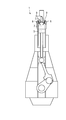
- FIG. 1 is a schematic view showing an example of a dual fuel engine.
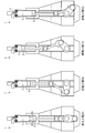
- FIG. 2 is a schematic view showing an example of the operation of the dual fuel engine.
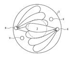
- FIG. 3 is a plan view schematically showing an example of a state in which fuel is injected into the combustion chamber in the dual fuel mode.
- FIG. 4 is a view schematically showing an example of a state in which the fuel is burned in the dual fuel mode.
- FIG. 5 is a plan view schematically showing an example of a state in which the fuel is burned in the dual fuel mode.
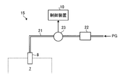
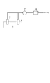
- FIG. 6 is a schematic view showing an example of the gaseous fuel supply system.
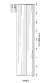
- FIG. 7 is a view showing the relationship between the crank angle and the pressure of the supply flow passage when the gaseous fuel injection valve and the gate valve are operating normally.
- FIG. 7 is a view showing the relationship between the crank angle and the pressure of the supply flow passage when the gaseous fuel injection valve and the gate valve are operating normally.
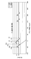
- FIG. 8 is a view showing the relationship between the crank angle and the pressure of the supply passage when the gate valve is abnormally opened.
- FIG. 9 is a view showing the relationship between the crank angle and the pressure of the supply flow passage when the gate valve is abnormally closed.
- FIG. 10 is a view showing the relationship between the crank angle and the pressure of the supply passage when the gaseous fuel injection valve is abnormally opened.
- FIG. 11 is a view showing the relationship between the crank angle and the pressure of the supply passage when the gaseous fuel injection valve is abnormally closed.
- FIG. 12 is a view showing the relationship between the crank angle and the pressure of the supply passage when the gas fuel injection valve is abnormally opened in the fuel oil dedicated mode.
- FIG. 13 is a schematic view showing an example of a gaseous fuel supply system.
- FIG. 13 is a schematic view showing an example of a gaseous fuel supply system.
- FIG. 14 is a view showing the relationship between the crank angle and the pressure of the supply passage when the pre-injection valve is abnormally opened.
- FIG. 15 is a view showing the relationship between the crank angle and the pressure of the supply flow passage when the pre-injection valve is abnormally closed.
- FIG. 1 is a schematic view showing an example of a dual fuel engine 1 according to the present embodiment.
- the dual fuel engine 1 according to the present embodiment includes a cross-head type diesel engine, and is used, for example, as a propulsion engine for ships and the like.
- the dual fuel engine 1 includes a base plate 50, a frame (main body) 51 provided on the base plate 50, and a jacket 52 provided on the frame 51.
- a cylinder 2 provided in a jacket 52, a piston 3 reciprocating in the cylinder 2, a piston rod 41 connected to the piston 3, a connecting rod 43, and a piston rod 41.
- a crosshead 42 connecting the connecting rod 43 and a crankshaft 4 connected to the connecting rod 43 via a crankpin 44 are provided.
- the cylinder 2 has a cylinder liner 2A provided on the jacket 52 and a cylinder cover 2B provided on the cylinder liner 2A.
- the cross head 42 moves along a guide portion 51 G provided on the frame 51 to transmit mechanical power from the piston rod 41 to the connecting rod 43.
- the crankshaft 4 is disposed on the base plate 50 and outputs mechanical power transmitted from the piston 3.
- the top surface of the piston 3 and the ceiling surface of the cylinder 2 face each other.
- An exhaust valve 11 is provided at the center of the ceiling surface of the cylinder 2.
- a combustion chamber 7 is formed between the piston 3, the cylinder 2 and the exhaust valve 11.
- the dual fuel engine 1 further includes a gas fuel supply system 15 including a detection device 6 for detecting a rotation angle (crank angle) of the crankshaft 4 and a gas fuel injection valve 8 for supplying the gas fuel PG to the combustion chamber 7.
- a liquid fuel supply system 20 including a liquid fuel injection valve 9 for supplying liquid fuel FO to the combustion chamber 7, an in-cylinder sensor 16 for detecting the pressure in the combustion chamber 7, and a control device 10 for controlling the dual fuel engine 1 Have.
- the gaseous fuel injection valve 8 can inject the gaseous fuel PG into the combustion chamber 7.
- the gaseous fuel PG includes, for example, at least one of CNG (compressed natural gas) and H 2 (hydrogen gas).
- CNG compressed natural gas
- H 2 hydrogen gas
- two gaseous fuel injection valves 8 are disposed in the combustion chamber 7.
- the number of gaseous fuel injection valves 8 is arbitrary.
- the liquid fuel injection valve 9 can inject the liquid fuel FO into the combustion chamber 7.
- the liquid fuel FO includes, for example, at least one of light oil, heavy oil, and heavy oil.
- two liquid fuel injection valves 9 are disposed in the combustion chamber 7.
- the number of liquid fuel injection valves 9 is arbitrary.
- the detection device 6 includes a crank angle sensor, and detects a crank angle of the crankshaft 4.
- the detection device 6 may detect the crank angle with reference to the top dead center of the piston 3.
- the crank angle sensor for example, detects a crank angle from the rotational position of a measurement member (disk, detection gear, etc.) mounted on the crankshaft 4 and outputs a crank angle signal.
- the crank angle sensor may be optical or electromagnetic.
- the detection device 6 may detect the crank angle from the rotational position of the crankshaft 4 or the position of the piston 3 or the like.
- the top dead center sensor is used to detect positional information (reference positional information) of the crankshaft 4 when the piston 3 is positioned at the top dead center, and based on the positional information and the rotational speed information of the crankshaft 4 The crank angle may be determined.
- the detection result of the detection device 6 is output to the control device 10.
- the crank angle and the position of the piston 3 are associated.
- the control device 10 can determine the position of the piston 3 including the top dead center and the bottom dead center based on the detection result of the detection device 6. Also, based on the output of the built-in timer and the detection result of the detection device 6, the control device 10, for example, the time when the piston 3 is arranged at the top dead center and the time when the piston 3 is arranged at the bottom dead center You can ask for
- the control device 10 controls the opening / closing of the exhaust valve 11, the injection of the gaseous fuel PG from the gaseous fuel injection valve 8, and the injection of the liquid fuel FO from the liquid fuel injection valve 9 based on the crank angle.
- the in-cylinder sensor 16 detects the pressure in the combustion chamber 7.
- the detection result of the in-cylinder sensor 16 is input to the control device 10.
- the control device 10 can determine the presence or absence of an abnormality in the combustion chamber 7 based on the detection result of the in-cylinder sensor 16.
- the control device 10 can obtain the type (content) of the abnormality of the combustion chamber 7 based on the detection result of the in-cylinder sensor 16.
- the abnormality of the combustion chamber 7 includes at least one of a combustion abnormality, oversupply of gaseous fuel, and undersupply of gaseous fuel.
- Combustion abnormalities include misfires.
- the pressure in the combustion chamber 7 differs between the normal state and the abnormal state of the combustion chamber 7. Further, the pressure of the combustion chamber 7 also differs depending on the type of abnormality of the combustion chamber 7.
- the relationship between the type of abnormality of the combustion chamber 7 and the pressure of the combustion chamber 7 corresponding to the type of abnormality is obtained in advance. The relationship is determined by preliminary experiments or simulations, and stored in a storage device connected to the control device 10.
- the control device 10 can determine the presence or absence of an abnormality in the combustion chamber 7 based on the detection result of the in-cylinder sensor 16 and the storage information of the storage device, and can determine the type of the abnormality if an abnormality occurs. It is.
- FIG. 2 is a schematic view showing an example of the operation of the dual fuel engine 1.
- the dual fuel engine 1 is a two-stroke one-cycle uniflow swept exhaust diesel engine, and new air is introduced from the scavenging port into the combustion chamber 7 when the piston 3 is disposed near the bottom dead center. During the transition from the top dead center to the bottom dead center, the gas in the combustion chamber 7 is exhausted from the exhaust port.
- the operation of the dual fuel engine 1 includes a suction step (A) for taking in new air and sending it to the combustion chamber 7, a compression step (B) for compressing the air in the combustion chamber 7 by the piston 3, and injecting fuel into the combustion chamber 7. And an exhaust process (D) in which the gas in the combustion chamber 7 after the combustion process is discharged from the exhaust valve 11.
- the dual fuel engine 1 can operate in a fuel oil dedicated mode using only liquid fuel FO and a dual fuel mode using both liquid fuel FO and gaseous fuel PG.
- the fuel oil dedicated mode is a mode in which the liquid fuel FO is supplied from the liquid fuel injection valve 9 to the combustion chamber 7 to burn the liquid fuel FO while the gaseous fuel injection valve 8 does not supply the gaseous fuel PG to the combustion chamber 7 .
- the liquid fuel FO is injected from the liquid fuel injection valve 9 to the combustion chamber 7 in the combustion step.
- the dual fuel mode is a mode in which both the liquid fuel FO and the gaseous fuel PG are supplied to the combustion chamber 7.
- a small amount of liquid fuel FO is injected from the liquid fuel injection valve 9 to the fuel chamber 7 to generate a pilot flame.
- the pilot flame ignites the gaseous fuel PG and burns it.
- FIG. 3 schematically shows an example in which the gaseous fuel PG is injected from the gaseous fuel valve 8 to the combustion chamber 7 and the liquid fuel FO is injected from the liquid fuel valve 9 to the combustion chamber 7 in the dual fuel mode. It is a top view shown.
- FIG. 4 is a view schematically showing an example of a state in which each of the liquid fuel FO and the gaseous fuel PG is burning in the dual fuel mode.
- FIG. 5 is a plan view schematically showing an example of a state in which the liquid fuel FO and the gaseous fuel PG are burning in the dual fuel mode.
- the air in the combustion chamber 7 is compressed.
- gaseous fuel PG is injected from the gaseous fuel injection valve 8 to the combustion chamber 7.
- a small amount of liquid fuel FO is injected from the liquid fuel injection valve 9 into the combustion chamber 7.
- the main fuel is a gaseous fuel PG.
- the gaseous fuel injection valve 8 has a plurality of injection ports 8S for injecting the gaseous fuel PG.
- the liquid fuel injection valve 9 has a plurality of injection ports 9S for injecting the liquid fuel FO.
- the gaseous fuel injection valve 8 injects gaseous fuel PG outward in the radial direction with respect to the axis of the gaseous fuel injection valve 8.
- the liquid fuel injection valve 9 injects the liquid fuel FO outward in the radial direction with respect to the axis of the liquid fuel injection valve 9.
- Each of the gaseous fuel injection valve 8 and the liquid fuel injection valve 9 injects the gaseous fuel PG and the liquid fuel FO so that the gaseous fuel PG and the liquid fuel FO intersect.
- the gaseous fuel injection valve 8 injects gaseous fuel PG at a pressure P1.
- diffusion combustion occurs in the combustion chamber 7 by supplying the high-pressure gaseous fuel PG to the combustion chamber 7 in which the high temperature and high pressure air is filled and the pilot flame is generated.
- the dual fuel mode burns the gaseous fuel PG by the diffusion combustion method.
- FIG. 6 is a view showing an example of the gaseous fuel supply system 15 according to the present embodiment.
- the gaseous fuel supply system 15 supplies gaseous fuel PG to the combustion chamber 7 of the dual fuel engine 1.
- the gaseous fuel supply system 15 is controlled by the controller 10.
- the gaseous fuel supply system 15 opens and closes the gaseous fuel injection valve 8 for injecting the gaseous fuel PG into the combustion chamber 7, the supply flow path 21 through which the gaseous fuel PG supplied to the gaseous fuel injection valve 8 flows, and the supply flow path 21.
- a possible gate valve 22 and a pressure sensor 23 for detecting the pressure of the supply flow path 21 between the gaseous fuel injection valve 8 and the gate valve 22 are provided.
- the gaseous fuel injection valve 8 and the gate valve 22 are controlled by the controller 10.
- the detection result of the pressure sensor 23 is output to the control device 10.
- the gate valve 22 is connected to a gaseous fuel source including a pump capable of delivering the gaseous fuel PG.
- the gaseous fuel supply source supplies gaseous fuel PG to the gate valve 22.
- the gaseous fuel supply source supplies gaseous fuel PG at pressure P1.
- the gate valve 22 functions as a safety valve (interlock mechanism). By opening both the gaseous fuel injection valve 8 and the gate valve 22, the gaseous fuel PG from the gaseous fuel supply source is supplied to the combustion chamber 7 through the gate valve 22, the supply flow passage 21 and the gaseous fuel injection valve 8. Supplied.
- the pressure sensor 23 detects the pressure of the supply flow passage 21 between the gaseous fuel injection valve 8 and the gate valve 22.
- the pressure sensor 23 can detect the pressure at the inlet of the gaseous fuel injection valve 8.
- the detection result of the pressure sensor 23 is output to the control device 10.
- the control device 10 detects an abnormality of at least one of the gas fuel injection valve 8 and the gate valve 22 based on the detection result of the pressure sensor 23 and the detection result of the detection device 6.
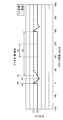
- FIG. 7 is a view showing the relationship between the crank angle when the gaseous fuel injection valve 8 and the gate valve 22 operate normally and the pressure of the supply flow passage 21 (pressure at the inlet of the gaseous fuel injection valve 8). is there.
- FIG. 7 includes a timing chart of the opening and closing operation of the gaseous fuel injection valve 8 and the opening and closing operation of the gate valve 22.
- FIG. 7 shows the pressure of the supply flow passage 21 between the gaseous fuel injection valve 8 and the gate valve 22 when the crank angle is in the range of -30 degrees to 90 degrees.
- the controller 10 outputs a command signal to open the gaseous fuel injection valve 8 after opening the gate valve 22 in order to supply the gaseous fuel PG to the combustion chamber 7.
- the controller 10 opens the gate valve 22 when the piston 3 is located near the top dead center.
- the control device 10 outputs a command signal to open the gate valve 22.
- the control device 10 opens the gaseous fuel injection valve 8 when the piston 3 is located near the top dead center.
- the control device 10 when the crank angle becomes A2 degrees, the control device 10 outputs a command signal to open the gaseous fuel injection valve 8.
- T1 from when the crank angle becomes A1 degree to A2 degree, the gate valve 22 is open and the gaseous fuel injection valve 8 is closed.
- the gaseous fuel PG of pressure P1 is supplied to the gate valve 22 from a gaseous fuel supply source.
- the gate valve 22 By opening the gate valve 22 in a state where the gaseous fuel injection valve 8 is closed, the pressure of the supply flow passage 21 between the gaseous fuel injection valve 8 and the gate valve 22 becomes the pressure P1 in the period T1.
- the gaseous fuel injection valve 8 When the crank angle becomes A2 degrees, the gaseous fuel injection valve 8 is opened in a state where the gate valve 22 is open, whereby the gaseous fuel PG is injected from the gaseous fuel injection valve 8 to the combustion chamber 7.
- the crank angle A2 is 0 degree. That is, when the piston 3 is disposed at the top dead center, the gaseous fuel PG is injected from the gaseous fuel injection valve 8.
- the crank angle A2 may not be 0 degrees.
- the control device 10 outputs a command signal to close the gate valve 22 after closing the gaseous fuel injection valve 8.
- the control device 10 when the crank angle becomes A3 degrees, the control device 10 outputs a command signal to close the gaseous fuel injection valve 8.
- the control device 10 When the crank angle becomes A4 degrees larger than A3 degrees, the control device 10 outputs a command signal to close the gate valve 22.
- both the gaseous fuel injection valve 8 and the gate valve 22 are open.
- the pressure in the supply flow passage 21 between the gaseous fuel injection valve 8 and the gate valve 22 gradually decreases.
- the controller 10 closes the gaseous fuel injection valve 8 with the gate valve 22 open.
- the pressure in the supply flow path 21 between the gaseous fuel injection valve 8 and the gate valve 22 gradually increases.
- the controller 10 closes the gate valve 22 with the gaseous fuel injection valve 8 closed.
- the pressure of the supply flow path 21 between the gaseous fuel injection valve 8 and the gate valve 22 becomes constant.
- the gate valve 22 is closed before the pressure of the supply flow passage 21 between the gaseous fuel injection valve 8 and the gate valve 22 rises to the pressure P1.
- the pressure of the supply flow passage 21 in the period T4 is a pressure P2 lower than the pressure P1.
- the period T1 includes a period from when a command signal for opening the gate valve 22 is output until a command signal for opening the gaseous fuel injection valve 8 is output.
- the period T2 includes a period from when a command signal for opening the gaseous fuel injection valve 8 is output to when a command signal for closing the gaseous fuel injection valve 8 is output.
- a period T3 includes a period from when a command signal for closing the gaseous fuel injection valve 8 is output to when a command signal for closing the gate valve 22 is output.
- a period T4 includes a period from when a command signal for closing the gate valve 22 is output until a command signal for opening the gate valve 22 is output in the next cycle.
- the control device 10 determines the timing for outputting the command signal based on the detection result of the detection device 6.
- FIG. 8 is a diagram showing an abnormality (open abnormality) in which the gate valve 22 is open even though the control device 10 outputs a command signal to close the gate valve 22.
- the horizontal axis is the crank angle
- the vertical axis is the pressure of the supply flow path 21 between the gaseous fuel injection valve 8 and the gate valve 22 (pressure at the inlet of the gaseous fuel injection valve 8).
- the controller 10 outputs a command signal to open the gate valve 22 when the crank angle is A1 degree, and opens the gaseous fuel injection valve 8 when the crank angle is A2 degree.
- a command signal is output, and when the crank angle is A3 degrees, a command signal for closing the gaseous fuel injection valve 8 is output, and when the crank angle is A4 degrees, a command signal for closing the gate valve 22 is output.
- the period T4 includes the time when the piston 3 is located near the bottom dead center. That is, the period T4 includes the time when the crank angle is 180 degrees.
- the pressure of the supply flow passage 21 in the period T4 when the gaseous fuel injection valve 8 and the gate valve 22 operate normally is the pressure P2.
- the pressure of the supply flow passage 21 in the period T4 differs between when the gate valve 22 is abnormal (open abnormality) and when it is normal. That is, when the gate valve 22 is normal, the pressure of the supply channel 21 in the period Th (period T4) is the pressure P2 as shown by the solid line in FIG.
- the pressure of the supply flow channel 21 in the period Th is a pressure P1 higher than the pressure P2, as shown by a dotted line in FIG. Therefore, the control device 10 determines whether the gate valve 22 is abnormal or not based on the detection result of the pressure sensor 23 in at least a part of the period Th of the period T4 when the piston 3 is disposed near the bottom dead center. It can be detected.
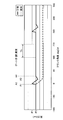
- FIG. 9 is a view showing the relationship between the crank angle and the pressure of the supply flow passage 21 (pressure at the inlet of the gaseous fuel injection valve 8) when the gate valve 22 is in abnormal closing.
- the gate valve 22 does not open, and at the crank angle A2, when the gaseous fuel injection valve 8 opens, the gate With the valve 22 closed, the gaseous fuel PG in the supply passage 21 is injected from the gaseous fuel injection valve 8 into the combustion chamber 7.
- the pressure of the supply flow passage 21 decreases from the time of the crank angle A2.
- the pressure of the supply flow path 21 in the period T2, the period T3, and the period T4 differs depending on whether the gate valve 22 is abnormal (closed abnormality) or normal.
- the control device 10 can detect, for example, whether or not the gate valve 22 is abnormal, based on the detection result of the pressure sensor 23 in the period Th.
- FIG. 10 is a view showing the relationship between the crank angle and the pressure of the supply flow passage 21 (pressure at the inlet of the gaseous fuel injection valve 8) when the gaseous fuel injection valve 8 is abnormally opened.
- the gaseous fuel injection valve 8 does not close and at the crank angle A4, the gate valve 22 closes. With the gate valve 22 closed, the gaseous fuel PG in the supply flow passage 21 is injected from the gaseous fuel injection valve 8 into the combustion chamber 7. As a result, as shown in FIG. 10, the pressure of the supply flow passage 21 decreases from the time of the crank angle A3. Thus, the pressure of the supply flow path 21 in the period T3 and the period T4 (period Th) differs depending on whether the gaseous fuel injection valve 8 is abnormal (open abnormality) or normal.
- the control device 10 can detect, for example, whether or not the gate valve 22 is abnormal, based on the detection result of the pressure sensor 23 in the period Th.
- FIG. 11 is a view showing the relationship between the crank angle and the pressure of the supply flow passage 21 (pressure at the inlet of the gaseous fuel injection valve 8) when the gaseous fuel injection valve 8 is abnormally closed.
- the command signal to open the gaseous fuel injection valve 8 is output from the control device 10
- the gaseous fuel injection valve 8 closes and the gate valve 22
- the gaseous fuel PG of the pressure P1 from the gaseous fuel supply source is supplied to the supply flow passage 21.
- the pressure of the supply flow path 21 in the period T2, the period T3, and the period T4 becomes the pressure P1.
- the pressure of the supply flow passage 21 in the period T2, the period T3, and the period T4 (period Th) differs depending on whether the gaseous fuel injection valve 8 is abnormal (closed abnormality) or normal.
- the control device 10 can detect, for example, whether or not the gate valve 22 is abnormal, based on the detection result of the pressure sensor 23 in the period Th.
- the pressure shown in FIG. 8 pressure when the gate valve 22 is abnormally opened
- the pressure shown in FIG. 11 pressure when the gaseous fuel injection valve 8 is abnormally closed
- T2 and period T3 pressure when the gaseous fuel injection valve 8 is abnormally closed
- the control device 10 causes an abnormality in either the gaseous fuel injection valve 8 or the gate valve 22 based on the detection result of the pressure sensor 23 and the detection result of the in-cylinder sensor 16 that detects the pressure of the combustion chamber 7. You may determine the height.
- the pressure in the combustion chamber 7 differs between when the gate valve 22 is abnormally open and when the gaseous fuel injection valve 8 is abnormally closed. For example, when the gaseous fuel injection valve 8 is closed abnormally, the gaseous fuel PG is not injected from the gaseous fuel injection valve 8 to the combustion chamber 7, so the possibility of misfiring in the combustion chamber 7 becomes high.
- the gaseous fuel PG is supplied to the combustion chamber 7 through the gate valve 22 and the gaseous fuel injection valve 8. Therefore, the possibility of misfiring in the combustion chamber 7 is low.
- the type of abnormality of the combustion chamber 7 is likely to be different between when the gate valve 22 is abnormally opened and when the gaseous fuel injection valve 8 is abnormally closed. Further, as described above, the pressure of the combustion chamber 7 differs depending on the type of abnormality of the combustion chamber 7.
- the control device 10 can determine which of the gaseous fuel injection valve 8 and the gate valve 22 has an abnormality based on the detection result of the in-cylinder sensor 16 and the storage information of the storage device.
- the period T4 is different. It approximates in. Therefore, it may be difficult to determine which of the gate valve 22 and the gaseous fuel injection valve 8 is abnormal based on the detection result of the pressure sensor 23 in the period T4.
- the type of abnormality of the combustion chamber 7 is different and the pressure of the combustion chamber 7 is different between when the gate valve 22 is abnormally closed and when the gaseous fuel injection valve 8 is abnormally opened.
- the control device 10 can determine which of the gaseous fuel injection valve 8 and the gate valve 22 has an abnormality based on the detection result of the in-cylinder sensor 16 and the storage information of the storage device.
- the gaseous fuel injection is performed based on the detection result of the pressure of the supply flow passage 21 between the gaseous fuel injection valve 8 and the gate valve 22 and the detection result of the crank angle. At least one of an abnormality of the valve 8 and an abnormality of the gate valve 22 can be detected. Therefore, for example, appropriate measures can be taken to eliminate the abnormality. Moreover, the problem which continues using the gaseous fuel supply system 15 which abnormality has generate
- the gate valve 22 functions as a safety valve (interlock mechanism), and operates when the piston 3 is disposed near the top dead center in order to inject the gaseous fuel PG. Since the gaseous fuel injection valve 8 operates with the gate valve 22 open, the gaseous fuel PG is injected from the gaseous fuel injection valve 8 to the combustion chamber 7 at an appropriate timing. Since the gaseous fuel injection valve 8 and the gate valve 22 operate in a state where the piston 3 is disposed near the top dead center, the pressure sensor 23 in the period Th when the piston 3 is disposed near the bottom dead center An abnormality in at least one of the gaseous fuel injection valve 8 and the gate valve 22 can be smoothly detected based on the detection result.
- a safety valve interlock mechanism
- the detection result of the pressure sensor 23 when an abnormality occurs in the gaseous fuel injection valve 8 in the period Th and the detection result of the pressure sensor 23 when an abnormality occurs in the gate valve 22 Even in the case of approximation, it is possible to determine which of the gaseous fuel injection valve 8 and the gate valve 22 has an abnormality by referring to the detection result of the in-cylinder sensor 16.
- a temperature sensor capable of detecting the temperature of the gas (exhaust gas) discharged from the combustion chamber 7 through the exhaust port 12 is provided, and the detection result of the temperature sensor and the detection of the pressure sensor 23 Based on the result, it may be determined which of the gaseous fuel injection valve 8 and the gate valve 22 has an abnormality. Even when the detection result of the pressure sensor 23 when abnormality occurs in the gaseous fuel injection valve 8 and the detection result of the pressure sensor 23 when abnormality occurs in the gate valve 22 in the period Th approximates that temperature sensor It is possible to determine which of the gaseous fuel injection valve 8 and the gate valve 22 has an abnormality by referring to the detection result of the above.
- the temperature of the exhaust gas discharged from the exhaust port 12 differs depending on the type of abnormality of the combustion chamber 7. Therefore, when the detection result of the pressure sensor 23 when an abnormality occurs in the gaseous fuel injection valve 8 and the detection result of the pressure sensor 23 when an abnormality occurs in the gate valve 22 approximates, the exhaust gas detected by the temperature sensor Based on the temperature detection result, it can be determined which of the gaseous fuel injection valve 8 and the gate valve 22 has an abnormality.
- the control device 10 By storing the relationship between the type of abnormality of the combustion chamber 7 and the temperature of the exhaust gas corresponding to the type of abnormality in the storage device, the control device 10 detects the detection result of the temperature sensor and the storage information of the storage device It is possible to determine which of the gaseous fuel injection valve 8 and the gate valve 22 has an abnormality based on
- an example of detecting an abnormality of the gaseous fuel injection valve 8 will be described based on the detection result of the pressure sensor 23 in the fuel oil dedicated mode.
- the gaseous fuel PG is not supplied from the gaseous fuel supply source, and the controller 10 outputs a command signal to close the gaseous fuel injection valve 8.
- the gaseous fuel injection valve 8 operates normally, the gaseous fuel injection valve 8 is closed, and the gaseous fuel PG is not injected from the gaseous fuel injection valve 8.
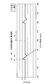
- FIG. 12 is a diagram showing the relationship between the crank angle and the pressure of the supply flow passage 21 (pressure at the inlet of the gaseous fuel injection valve 8) when the gaseous fuel injection valve 8 is normal and open abnormality in the fuel oil dedicated mode It is.
- the horizontal axis is the crank angle
- the vertical axis is the pressure of the supply flow path 21 between the gaseous fuel injection valve 8 and the gate valve 22 (pressure at the inlet of the gaseous fuel injection valve 8).
- the output of the pressure sensor 23 is constant.
- the gaseous fuel injection valve 8 is abnormal (when it is open) in the fuel oil dedicated mode, high temperature / high pressure gas in the combustion chamber 7 flows from the gaseous fuel injection valve 8 into the supply flow passage 21. Thereby, the pressure of the supply flow path 21 rises. The pressure in the supply channel 21 is detected by the pressure sensor 23. Therefore, based on the detection result of the pressure sensor 23, the control device 10 can detect whether or not an abnormality has occurred in the gaseous fuel injection valve 8 in the fuel oil dedicated mode.
- FIG. 13 is a schematic view showing an example of the gaseous fuel supply system 15 according to the present embodiment.
- the gaseous fuel supply system 15 includes a gaseous fuel injection valve 8 for injecting the gaseous fuel PG into the combustion chamber 7 and a pre-injection valve 30.
- the pre-injection valve 30 is controlled by the control device 10.
- the pre-injection valve 30 injects the gaseous fuel PG into the combustion chamber 7.
- the pre-injection valve 30 injects the gaseous fuel PG into the combustion chamber 7 before injecting the gaseous fuel PG from the gaseous fuel injection valve 8.
- the gaseous fuel PG is further generated from the gaseous fuel injection valve 8. Combustion is performed in the combustion chamber 7 by injection of
- FIG. 14 is a diagram showing the relationship between the crank angle in the partial premixed combustion mode in which partial premixed combustion is performed and the pressure of the supply flow passage 21 (pressure at the inlet of the gaseous fuel injection valve 8).
- the horizontal axis is the crank angle
- the vertical axis is the pressure of the supply flow path 21 between the gaseous fuel injection valve 8 and the gate valve 22 (pressure at the inlet of the gaseous fuel injection valve 8).
- FIG. 14 shows the relationship between the crank angle and the pressure of the supply flow passage 21 when the pre-injection valve 30 is normal and the opening abnormality.
- the injection of the gaseous fuel PG from the pre-injection valve 30 is performed before the injection of the gaseous fuel PG from the gaseous fuel injection valve 8 is performed.
- the operation of the gaseous fuel injection valve 8 and the gate valve 22 when injecting the gaseous fuel PG from the gaseous fuel injection valve 8 is the same as that of the above-described embodiment. That is, the control device 10 opens the gate valve 22 when the crank angle is A1 degree and opens the gas fuel injection valve 8 when the crank angle is A2 degree, and the gas fuel injection valve 8 when the crank angle is A3 degree. Is closed, and when the crank angle is A4 degrees, a command signal is output to close the gate valve 22.
- the sequence of opening and closing the gate valve 22 and the pre-injection valve 30 when injecting the gaseous fuel PG from the pre-injection valve 30 is the same as the gate valve 22 and the gaseous fuel injection valve 8 when injecting the gaseous fuel PG from the gaseous fuel injection valve 8 It is similar to the sequence of opening and closing of. That is, when injecting the gaseous fuel PG from the pre-injection valve 30, the control device 10 opens the gate valve 22 when the crank angle is A1p degree and opens the pre-injection valve 30 when the crank angle is A2p degree. When the angle is A3 p degrees, the pre injection valve 30 is closed, and when the crank angle is A4 p degrees, the pre injection valve 30 is closed.
- the control device 10 closes the pre-injection valve 30 which injected the gaseous fuel PG at the crank angle A3 p and closes the gate valve 22 at the crank angle A4 p, and then the gaseous fuel PG is injected from the gaseous fuel injection valve 8 Thus, the command signal is output to open the gate valve 22 at the crank angle A1.
- an abnormality in which the pre-injection valve 30 is open although the control device 10 outputs a command signal to close the pre-injection valve 30 will be described.
- the gate valve 22 is closed at the crank angle A4p without the pre-injection valve 30 closing. With the valve 22 closed, the gaseous fuel PG is injected from the pre-injection valve 30 into the combustion chamber 7. As a result, as shown in FIG. 14, the pressure of the supply flow channel 21 decreases from the time of the crank angle A3 p.
- the command signal for closing the pre-injection valve 30 is output at the crank angle A3 p, and then the gate valve 22 is output at the crank angle A1.
- the pressure in the supply channel 21 in the period Tj until the command signal for opening is output is different. That is, when the pre-injection valve 30 is normal, the pressure of the supply flow passage 21 in the period Tj is the pressure P2 as shown by the solid line in FIG. 14. When the pre-injection valve 30 is abnormally opened, the period Tj The pressure of the supply flow passage 21 at the point of (4) is lower than the pressure P2, as shown by the dotted line in FIG. Therefore, the control device 10 can detect whether or not the pre-injection valve 30 is abnormal based on the detection result of the pressure sensor 23 in the period Tj.
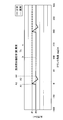
- FIG. 15 is a view showing the relationship between the crank angle and the pressure of the supply flow passage 21 (pressure at the inlet of the gaseous fuel injection valve 8) when the pre-injection valve 30 is abnormally closed.
- the command signal for opening the pre-injection valve 30 is output from the control device 10
- the pre-injection valve 30 does not open, the pre-injection valve 30 is closed and the gate valve 22 is open.
- the gaseous fuel PG at the pressure P1 is supplied to the supply flow channel 21.
- the pressure of the supply flow path 21 in the period Tj becomes the pressure P1.
- the pressure of the supply flow passage 21 in the period Tj differs between when the pre-injection valve 30 is abnormal (closed abnormality) and when it is normal. That is, when the pre-injection valve 30 is normal, the pressure of the supply flow passage 21 in the period Tj is the pressure P2 as shown by the solid line in FIG.
- the period Tj The pressure of the supply flow passage 21 at the pressure point P2 is a pressure P1 higher than the pressure P2, as shown by a dotted line in FIG. Therefore, based on the detection result of the pressure sensor 23 in the period Tj, it can be detected whether or not the pre-injection valve 30 is abnormal.
- Reference Signs List 1 dual fuel engine 7 combustion chamber 8 gas fuel injection valve 15 gas fuel supply system 16 in-cylinder sensor 21 supply flow path 22 gate valve 23 pressure sensor 30 pre-injection valve PG gas fuel
Abstract
Description
第1実施形態について説明する。図1は、本実施形態に係るデュアルフューエルエンジン1の一例を示す模式図である。本実施形態に係るデュアルフューエルエンジン1は、クロスヘッド型ディーゼルエンジンを含み、例えば、船舶等の推進用エンジンとして使用される。 First Embodiment
The first embodiment will be described. FIG. 1 is a schematic view showing an example of a
第2実施形態について説明する。以下の実施形態において、上述の実施形態と同一又は同等の構成部分については同一の符号を付し、その説明を簡略又は省略する。 Second Embodiment
The second embodiment will be described. In the following embodiments, the same or equivalent components as or to those of the above-described embodiments are denoted by the same reference numerals, and the description thereof will be simplified or omitted.
第3実施形態について説明する。以下の実施形態において、上述の実施形態と同一又は同等の構成部分については同一の符号を付し、その説明を簡略又は省略する。 Third Embodiment
A third embodiment will be described. In the following embodiments, the same or equivalent components as or to those of the above-described embodiments are denoted by the same reference numerals, and the description thereof will be simplified or omitted.
7 燃焼室
8 気体燃料噴射弁
15 気体燃料供給システム
16 筒内センサ
21 供給流路
22 ゲート弁
23 圧力センサ
30 プレ噴射弁
PG 気体燃料
Claims (6)
- エンジンの燃焼室に気体燃料を供給する気体燃料供給システムであって、
前記燃焼室に前記気体燃料を噴射する噴射弁と、
前記噴射弁に供給される前記気体燃料が流れる供給流路と、
前記供給流路を開閉可能なゲート弁と、
前記噴射弁と前記ゲート弁との間の前記供給流路の圧力を検出する圧力センサと、
前記噴射弁及び前記ゲート弁を制御する制御装置と、を備え、
前記圧力センサの検出結果と前記エンジンのクランク軸のクランク角度を検出する検出装置の検出結果とに基づいて、前記噴射弁及び前記ゲート弁の少なくとも一方の異常を検出する気体燃料供給システム。 A gaseous fuel supply system for supplying gaseous fuel to a combustion chamber of an engine, comprising:
An injection valve for injecting the gaseous fuel into the combustion chamber;
A supply flow path through which the gaseous fuel supplied to the injection valve flows;
A gate valve capable of opening and closing the supply flow path;
A pressure sensor for detecting the pressure in the supply passage between the injection valve and the gate valve;
A controller for controlling the injection valve and the gate valve;
A gaseous fuel supply system for detecting an abnormality in at least one of the injection valve and the gate valve based on the detection result of the pressure sensor and the detection result of a detection device for detecting a crank angle of a crankshaft of the engine. - 前記制御装置は、前記検出装置の検出結果に基づいて上死点及び下死点を含む前記エンジンのピストンの位置を求め、前記燃焼室に前記気体燃料を供給するために、前記ピストンが上死点近傍に位置する時点おいて前記ゲート弁を開けた後、前記噴射弁を開け、前記噴射弁を閉じた後、前記ゲート弁を閉じるように指令信号を出力し、
前記ピストンが下死点近傍に位置する時点での前記圧力センサの検出結果に基づいて、前記異常を検出する請求項1に記載の気体燃料供給システム。 The control device determines the position of a piston of the engine including top dead center and bottom dead center based on the detection result of the detection device, and the piston is top dead to supply the gaseous fuel to the combustion chamber. After the gate valve is opened at a point near the point, the injection valve is opened, and after closing the injection valve, a command signal is output to close the gate valve,
The gaseous fuel supply system according to claim 1, wherein the abnormality is detected based on the detection result of the pressure sensor when the piston is located near the bottom dead center. - 前記圧力センサの検出結果と前記燃焼室の圧力を検出する筒内センサの検出結果とに基づいて、前記噴射弁及び前記ゲート弁のどちらに異常が生じたかを判定する請求項2に記載の気体燃料供給システム。 The gas according to claim 2, wherein it is determined which of the injection valve and the gate valve has an abnormality based on the detection result of the pressure sensor and the detection result of an in-cylinder sensor that detects the pressure of the combustion chamber. Fuel supply system.
- 前記噴射弁からの前記気体燃料の噴射前に、気体燃料を前記燃焼室に噴射するプレ噴射弁を備え、
前記制御装置は、前記気体燃料を噴射した前記プレ噴射弁を閉じてから前記ゲート弁を閉じた後、前記噴射弁からの前記気体燃料の噴射のために前記ゲート弁を開けるように指令信号を出力し、
前記プレ噴射弁を閉じるための指令信号が出力されてから前記ゲート弁を開くための指令信号が出力されるまでの期間における前記圧力センサの検出結果に基づいて、前記プレ噴射弁の異常を検出する請求項2又は請求項3に記載の気体燃料供給システム。 It has a pre-injection valve that injects gaseous fuel into the combustion chamber before injecting the gaseous fuel from the injection valve.
After closing the pre-injection valve that injected the gaseous fuel and closing the gate valve, the control device instructs the gate valve to open the gate valve for injection of the gaseous fuel from the injection valve. Output
An abnormality in the pre-injection valve is detected based on the detection result of the pressure sensor in a period from the output of the command signal for closing the pre-injection valve to the output of a command signal for opening the gate valve. The gaseous fuel supply system according to claim 2 or claim 3. - 前記エンジンは、デュアルフューエルエンジンを含み、
前記燃焼室に液体燃料が供給され前記気体燃料が供給されない燃料油専用モードにおける前記圧力センサの検出結果に基づいて、前記噴射弁の異常を検出する請求項1から請求項4のいずれか一項に記載の気体燃料供給システム。 The engine includes a dual fuel engine,
The abnormality of the said injection valve is detected based on the detection result of the said pressure sensor in the fuel oil exclusive mode in which liquid fuel is supplied to the said combustion chamber, and the said gaseous fuel is not supplied, The any one of Claims 1-4 The gaseous fuel supply system according to claim 1. - エンジンの燃焼室に気体燃料を供給する気体燃料供給システムの異常検出方法であって、
前記気体燃料供給システムは、前記燃焼室に気体燃料を噴射する噴射弁と、前記噴射弁に供給される前記気体燃料が流れる供給流路と、前記供給流路を開閉可能なゲート弁と、を備え、
前記噴射弁と前記ゲート弁との間の前記供給流路の圧力を検出する工程と、
前記エンジンのクランク軸のクランク角度を検出する工程と、
前記供給流路の圧力の検出結果と前記クランク角度の検出結果とに基づいて、前記噴射弁及び前記ゲート弁の少なくとも一方の異常を検出する工程と、を含む気体燃料供給システムの異常検出方法。 An anomaly detection method for a gaseous fuel supply system for supplying gaseous fuel to a combustion chamber of an engine, comprising:
The gaseous fuel supply system includes an injection valve for injecting the gaseous fuel into the combustion chamber, a supply flow path through which the gaseous fuel is supplied to the injection valve, and a gate valve capable of opening and closing the supply flow path. Equipped
Detecting the pressure in the supply passage between the injection valve and the gate valve;
Detecting a crank angle of a crankshaft of the engine;
And detecting the abnormality in at least one of the injection valve and the gate valve based on the detection result of the pressure in the supply passage and the detection result of the crank angle.
Priority Applications (2)
| Application Number | Priority Date | Filing Date | Title |
|---|---|---|---|
| CN201480059078.9A CN105849395B (en) | 2013-12-26 | 2014-12-12 | The method for detecting abnormality of gas fuel supply system and gas fuel supply system |
| KR1020167010947A KR101864971B1 (en) | 2013-12-26 | 2014-12-12 | Gas fuel supply system and method for detecting abnormality of gas fuel supply system |
Applications Claiming Priority (2)
| Application Number | Priority Date | Filing Date | Title |
|---|---|---|---|
| JP2013-270058 | 2013-12-26 | ||
| JP2013270058A JP6373578B2 (en) | 2013-12-26 | 2013-12-26 | Gaseous fuel supply system and abnormality detection method for gaseous fuel supply system |
Publications (1)
| Publication Number | Publication Date |
|---|---|
| WO2015098578A1 true WO2015098578A1 (en) | 2015-07-02 |
Family
ID=53478442
Family Applications (1)
| Application Number | Title | Priority Date | Filing Date |
|---|---|---|---|
| PCT/JP2014/083025 WO2015098578A1 (en) | 2013-12-26 | 2014-12-12 | Gas fuel supply system and method for detecting abnormality of gas fuel supply system |
Country Status (4)
| Country | Link |
|---|---|
| JP (1) | JP6373578B2 (en) |
| KR (1) | KR101864971B1 (en) |
| CN (1) | CN105849395B (en) |
| WO (1) | WO2015098578A1 (en) |
Cited By (1)
| Publication number | Priority date | Publication date | Assignee | Title |
|---|---|---|---|---|
| CN114622986A (en) * | 2020-12-09 | 2022-06-14 | 曼能源解决方案公司(德国曼能源解决方案股份公司子公司) | Internal combustion engine |
Families Citing this family (5)
| Publication number | Priority date | Publication date | Assignee | Title |
|---|---|---|---|---|
| DE102017115757A1 (en) * | 2017-07-13 | 2019-01-17 | Man Diesel & Turbo Se | Method and control device for operating an internal combustion engine |
| KR102439314B1 (en) * | 2017-10-24 | 2022-09-02 | 현대중공업 주식회사 | Engine for Ship |
| DK180386B1 (en) * | 2019-06-14 | 2021-02-24 | Man Energy Solutions Filial Af Man Energy Solutions Se Tyskland | Internal combustion engine |
| US11352965B2 (en) * | 2019-10-18 | 2022-06-07 | Caterpillar Inc. | Reverse flow detection system |
| CN114718722B (en) * | 2022-02-24 | 2023-03-21 | 潍柴动力股份有限公司 | Valve fault detection method and system for precombustion chamber air intake and engine |
Citations (5)
| Publication number | Priority date | Publication date | Assignee | Title |
|---|---|---|---|---|
| JP2000282956A (en) * | 1999-03-29 | 2000-10-10 | Honda Motor Co Ltd | Gas fuel supply system for vehicle |
| JP3432098B2 (en) | 1996-01-15 | 2003-07-28 | マーン・ベー・オグ・ドバルドヴェー・ディーゼール・アクティーゼルスカブ | Control method of fuel supply to high-pressure gas injection engine and its engine |
| JP2006329135A (en) * | 2005-05-30 | 2006-12-07 | Nikki Co Ltd | Diagnostic method for fuel supply system |
| JP2009013992A (en) * | 2008-09-17 | 2009-01-22 | Toyota Motor Corp | Protection control method for gas fuel injection valve of bifuel cylinder direct injection engine |
| JP2012132418A (en) * | 2010-12-24 | 2012-07-12 | Kawasaki Heavy Ind Ltd | Apparatus and method for detecting failure of fuel supply valve in gas engine |
Family Cites Families (6)
| Publication number | Priority date | Publication date | Assignee | Title |
|---|---|---|---|---|
| JP2002070632A (en) * | 2000-08-25 | 2002-03-08 | Hitachi Ltd | Engine controller with failure diagnostic device |
| JP5518537B2 (en) * | 2010-03-18 | 2014-06-11 | 株式会社ケーヒン | Shut-off valve failure diagnosis device |
| JP5425677B2 (en) * | 2010-03-19 | 2014-02-26 | 株式会社ケーヒン | Fuel supply system and shut-off valve failure diagnosis device |
| WO2012086211A1 (en) * | 2010-12-24 | 2012-06-28 | 川崎重工業株式会社 | Gas fuel leakage detection method, and gas fuel leakage detection device, and gas engine equipped with same |
| ITMI20110547A1 (en) * | 2011-04-04 | 2012-10-05 | Landi Renzo Spa | METHOD AND DEVICE FOR DIAGNOSTICS OF GASEOUS FLUID LOSSES IN A FUEL SUPPLY CIRCUIT OF A MOTOR VEHICLE |
| JP5827587B2 (en) * | 2012-03-27 | 2015-12-02 | 株式会社ケーヒン | Fuel injection system |
-
2013
- 2013-12-26 JP JP2013270058A patent/JP6373578B2/en active Active
-
2014
- 2014-12-12 CN CN201480059078.9A patent/CN105849395B/en active Active
- 2014-12-12 WO PCT/JP2014/083025 patent/WO2015098578A1/en active Application Filing
- 2014-12-12 KR KR1020167010947A patent/KR101864971B1/en active IP Right Grant
Patent Citations (5)
| Publication number | Priority date | Publication date | Assignee | Title |
|---|---|---|---|---|
| JP3432098B2 (en) | 1996-01-15 | 2003-07-28 | マーン・ベー・オグ・ドバルドヴェー・ディーゼール・アクティーゼルスカブ | Control method of fuel supply to high-pressure gas injection engine and its engine |
| JP2000282956A (en) * | 1999-03-29 | 2000-10-10 | Honda Motor Co Ltd | Gas fuel supply system for vehicle |
| JP2006329135A (en) * | 2005-05-30 | 2006-12-07 | Nikki Co Ltd | Diagnostic method for fuel supply system |
| JP2009013992A (en) * | 2008-09-17 | 2009-01-22 | Toyota Motor Corp | Protection control method for gas fuel injection valve of bifuel cylinder direct injection engine |
| JP2012132418A (en) * | 2010-12-24 | 2012-07-12 | Kawasaki Heavy Ind Ltd | Apparatus and method for detecting failure of fuel supply valve in gas engine |
Cited By (1)
| Publication number | Priority date | Publication date | Assignee | Title |
|---|---|---|---|---|
| CN114622986A (en) * | 2020-12-09 | 2022-06-14 | 曼能源解决方案公司(德国曼能源解决方案股份公司子公司) | Internal combustion engine |
Also Published As
| Publication number | Publication date |
|---|---|
| CN105849395B (en) | 2019-10-18 |
| JP6373578B2 (en) | 2018-08-15 |
| CN105849395A (en) | 2016-08-10 |
| KR101864971B1 (en) | 2018-06-05 |
| KR20160060750A (en) | 2016-05-30 |
| JP2015124713A (en) | 2015-07-06 |
Similar Documents
| Publication | Publication Date | Title |
|---|---|---|
| WO2015098578A1 (en) | Gas fuel supply system and method for detecting abnormality of gas fuel supply system | |
| KR101411395B1 (en) | Two-stroke engine | |
| KR101725850B1 (en) | Uniflow scavenging 2-cycle engine | |
| KR101702549B1 (en) | Two-stroke uniflow engine | |
| EP2891780B1 (en) | Uniflow scavenging two-cycle engine | |
| US9334813B2 (en) | Control system for a dual-fuel engine | |
| JP5587091B2 (en) | 2-stroke gas engine | |
| JP5811539B2 (en) | 2-cycle engine | |
| KR101564867B1 (en) | Dual-fuel diesel engine and method for operating same | |
| WO2014034796A1 (en) | Uniflow scavenging two-cycle engine | |
| KR102206923B1 (en) | Ending operation of dual fuel engine in gaseous fuel mode | |
| DK3015679T3 (en) | Cylinder for a piston combustion engine, piston combustion engine and method for operating a piston combustion engine | |
| WO2014077002A1 (en) | Diesel engine control device, diesel engine, and diesel engine control method | |
| DK3015699T3 (en) | Gas supply system with a control system and cylinder for a piston combustion engine, piston combustion engine and method of operation of a piston combustion engine | |
| KR102442206B1 (en) | Ship Engine and Method for Ship Engine | |
| KR101817025B1 (en) | Gas fuel supply system, control device, and engine | |
| JP6872871B2 (en) | Gas supply system and cylinder liner for reciprocating piston internal combustion engine, reciprocating piston internal combustion engine, and operating method of reciprocating piston internal combustion engine | |
| JP6003288B2 (en) | Uniflow scavenging 2-cycle engine | |
| EP3336339A1 (en) | Controlling a dual-fuel internal combustion engine operated at least partly on gaseous fuel | |
| JP2015165106A (en) | Dual-fuel engine, ship with the same, and dual-fuel engine control method | |
| KR20180095637A (en) | Piston engine operating method and piston engine | |
| JP6128895B2 (en) | Premixed compression ignition engine and operation control method thereof | |
| JP2014101884A (en) | Two-stroke gas engine | |
| JP2017096134A (en) | Gas engine and ship |
Legal Events
| Date | Code | Title | Description |
|---|---|---|---|
| 121 | Ep: the epo has been informed by wipo that ep was designated in this application |
Ref document number: 14875316 Country of ref document: EP Kind code of ref document: A1 |
|
| REEP | Request for entry into the european phase |
Ref document number: 2014875316 Country of ref document: EP |
|
| WWE | Wipo information: entry into national phase |
Ref document number: 2014875316 Country of ref document: EP |
|
| ENP | Entry into the national phase |
Ref document number: 20167010947 Country of ref document: KR Kind code of ref document: A |
|
| NENP | Non-entry into the national phase |
Ref country code: DE |