JP6373578B2 - Gaseous fuel supply system and abnormality detection method for gaseous fuel supply system - Google Patents
Gaseous fuel supply system and abnormality detection method for gaseous fuel supply system Download PDFInfo
- Publication number
- JP6373578B2 JP6373578B2 JP2013270058A JP2013270058A JP6373578B2 JP 6373578 B2 JP6373578 B2 JP 6373578B2 JP 2013270058 A JP2013270058 A JP 2013270058A JP 2013270058 A JP2013270058 A JP 2013270058A JP 6373578 B2 JP6373578 B2 JP 6373578B2
- Authority
- JP
- Japan
- Prior art keywords
- gaseous fuel
- injection valve
- angle
- pressure
- gate valve
- Prior art date
- Legal status (The legal status is an assumption and is not a legal conclusion. Google has not performed a legal analysis and makes no representation as to the accuracy of the status listed.)
- Active
Links
- 239000000446 fuel Substances 0.000 title claims description 444
- 238000001514 detection method Methods 0.000 title claims description 146
- 230000005856 abnormality Effects 0.000 title claims description 102
- 238000002347 injection Methods 0.000 claims description 333
- 239000007924 injection Substances 0.000 claims description 333
- 238000002485 combustion reaction Methods 0.000 claims description 122
- 239000007788 liquid Substances 0.000 claims description 50
- 230000002159 abnormal effect Effects 0.000 claims description 34
- 230000009977 dual effect Effects 0.000 claims description 23
- 239000000295 fuel oil Substances 0.000 claims description 23
- 238000000034 method Methods 0.000 claims description 3
- 238000010586 diagram Methods 0.000 description 26
- 239000007789 gas Substances 0.000 description 13
- 230000007423 decrease Effects 0.000 description 5
- 238000007906 compression Methods 0.000 description 3
- 238000009792 diffusion process Methods 0.000 description 2
- VNWKTOKETHGBQD-UHFFFAOYSA-N methane Chemical compound C VNWKTOKETHGBQD-UHFFFAOYSA-N 0.000 description 2
- 230000002000 scavenging effect Effects 0.000 description 2
- UFHFLCQGNIYNRP-UHFFFAOYSA-N Hydrogen Chemical compound [H][H] UFHFLCQGNIYNRP-UHFFFAOYSA-N 0.000 description 1
- 238000009841 combustion method Methods 0.000 description 1
- 238000007599 discharging Methods 0.000 description 1
- 239000002737 fuel gas Substances 0.000 description 1
- 239000008246 gaseous mixture Substances 0.000 description 1
- 230000007257 malfunction Effects 0.000 description 1
- 238000005259 measurement Methods 0.000 description 1
- 239000003345 natural gas Substances 0.000 description 1
- 239000003921 oil Substances 0.000 description 1
- 230000003287 optical effect Effects 0.000 description 1
- 238000004088 simulation Methods 0.000 description 1
- 230000007704 transition Effects 0.000 description 1
Images


Classifications
-
- F—MECHANICAL ENGINEERING; LIGHTING; HEATING; WEAPONS; BLASTING
- F02—COMBUSTION ENGINES; HOT-GAS OR COMBUSTION-PRODUCT ENGINE PLANTS
- F02D—CONTROLLING COMBUSTION ENGINES
- F02D19/00—Controlling engines characterised by their use of non-liquid fuels, pluralities of fuels, or non-fuel substances added to the combustible mixtures
- F02D19/06—Controlling engines characterised by their use of non-liquid fuels, pluralities of fuels, or non-fuel substances added to the combustible mixtures peculiar to engines working with pluralities of fuels, e.g. alternatively with light and heavy fuel oil, other than engines indifferent to the fuel consumed
- F02D19/0663—Details on the fuel supply system, e.g. tanks, valves, pipes, pumps, rails, injectors or mixers
- F02D19/0686—Injectors
- F02D19/0692—Arrangement of multiple injectors per combustion chamber
-
- F—MECHANICAL ENGINEERING; LIGHTING; HEATING; WEAPONS; BLASTING
- F02—COMBUSTION ENGINES; HOT-GAS OR COMBUSTION-PRODUCT ENGINE PLANTS
- F02D—CONTROLLING COMBUSTION ENGINES
- F02D19/00—Controlling engines characterised by their use of non-liquid fuels, pluralities of fuels, or non-fuel substances added to the combustible mixtures
- F02D19/06—Controlling engines characterised by their use of non-liquid fuels, pluralities of fuels, or non-fuel substances added to the combustible mixtures peculiar to engines working with pluralities of fuels, e.g. alternatively with light and heavy fuel oil, other than engines indifferent to the fuel consumed
- F02D19/0623—Failure diagnosis or prevention; Safety measures; Testing
-
- F—MECHANICAL ENGINEERING; LIGHTING; HEATING; WEAPONS; BLASTING
- F02—COMBUSTION ENGINES; HOT-GAS OR COMBUSTION-PRODUCT ENGINE PLANTS
- F02D—CONTROLLING COMBUSTION ENGINES
- F02D19/00—Controlling engines characterised by their use of non-liquid fuels, pluralities of fuels, or non-fuel substances added to the combustible mixtures
- F02D19/06—Controlling engines characterised by their use of non-liquid fuels, pluralities of fuels, or non-fuel substances added to the combustible mixtures peculiar to engines working with pluralities of fuels, e.g. alternatively with light and heavy fuel oil, other than engines indifferent to the fuel consumed
- F02D19/0639—Controlling engines characterised by their use of non-liquid fuels, pluralities of fuels, or non-fuel substances added to the combustible mixtures peculiar to engines working with pluralities of fuels, e.g. alternatively with light and heavy fuel oil, other than engines indifferent to the fuel consumed characterised by the type of fuels
- F02D19/0642—Controlling engines characterised by their use of non-liquid fuels, pluralities of fuels, or non-fuel substances added to the combustible mixtures peculiar to engines working with pluralities of fuels, e.g. alternatively with light and heavy fuel oil, other than engines indifferent to the fuel consumed characterised by the type of fuels at least one fuel being gaseous, the other fuels being gaseous or liquid at standard conditions
- F02D19/0647—Controlling engines characterised by their use of non-liquid fuels, pluralities of fuels, or non-fuel substances added to the combustible mixtures peculiar to engines working with pluralities of fuels, e.g. alternatively with light and heavy fuel oil, other than engines indifferent to the fuel consumed characterised by the type of fuels at least one fuel being gaseous, the other fuels being gaseous or liquid at standard conditions the gaseous fuel being liquefied petroleum gas [LPG], liquefied natural gas [LNG], compressed natural gas [CNG] or dimethyl ether [DME]
-
- F—MECHANICAL ENGINEERING; LIGHTING; HEATING; WEAPONS; BLASTING
- F02—COMBUSTION ENGINES; HOT-GAS OR COMBUSTION-PRODUCT ENGINE PLANTS
- F02D—CONTROLLING COMBUSTION ENGINES
- F02D19/00—Controlling engines characterised by their use of non-liquid fuels, pluralities of fuels, or non-fuel substances added to the combustible mixtures
- F02D19/06—Controlling engines characterised by their use of non-liquid fuels, pluralities of fuels, or non-fuel substances added to the combustible mixtures peculiar to engines working with pluralities of fuels, e.g. alternatively with light and heavy fuel oil, other than engines indifferent to the fuel consumed
- F02D19/0663—Details on the fuel supply system, e.g. tanks, valves, pipes, pumps, rails, injectors or mixers
- F02D19/0686—Injectors
- F02D19/0689—Injectors for in-cylinder direct injection
-
- F—MECHANICAL ENGINEERING; LIGHTING; HEATING; WEAPONS; BLASTING
- F02—COMBUSTION ENGINES; HOT-GAS OR COMBUSTION-PRODUCT ENGINE PLANTS
- F02D—CONTROLLING COMBUSTION ENGINES
- F02D19/00—Controlling engines characterised by their use of non-liquid fuels, pluralities of fuels, or non-fuel substances added to the combustible mixtures
- F02D19/06—Controlling engines characterised by their use of non-liquid fuels, pluralities of fuels, or non-fuel substances added to the combustible mixtures peculiar to engines working with pluralities of fuels, e.g. alternatively with light and heavy fuel oil, other than engines indifferent to the fuel consumed
- F02D19/08—Controlling engines characterised by their use of non-liquid fuels, pluralities of fuels, or non-fuel substances added to the combustible mixtures peculiar to engines working with pluralities of fuels, e.g. alternatively with light and heavy fuel oil, other than engines indifferent to the fuel consumed simultaneously using pluralities of fuels
- F02D19/081—Adjusting the fuel composition or mixing ratio; Transitioning from one fuel to the other
-
- F—MECHANICAL ENGINEERING; LIGHTING; HEATING; WEAPONS; BLASTING
- F02—COMBUSTION ENGINES; HOT-GAS OR COMBUSTION-PRODUCT ENGINE PLANTS
- F02D—CONTROLLING COMBUSTION ENGINES
- F02D41/00—Electrical control of supply of combustible mixture or its constituents
- F02D41/0025—Controlling engines characterised by use of non-liquid fuels, pluralities of fuels, or non-fuel substances added to the combustible mixtures
- F02D41/0027—Controlling engines characterised by use of non-liquid fuels, pluralities of fuels, or non-fuel substances added to the combustible mixtures the fuel being gaseous
-
- F—MECHANICAL ENGINEERING; LIGHTING; HEATING; WEAPONS; BLASTING
- F02—COMBUSTION ENGINES; HOT-GAS OR COMBUSTION-PRODUCT ENGINE PLANTS
- F02D—CONTROLLING COMBUSTION ENGINES
- F02D41/00—Electrical control of supply of combustible mixture or its constituents
- F02D41/22—Safety or indicating devices for abnormal conditions
- F02D41/221—Safety or indicating devices for abnormal conditions relating to the failure of actuators or electrically driven elements
-
- F—MECHANICAL ENGINEERING; LIGHTING; HEATING; WEAPONS; BLASTING
- F02—COMBUSTION ENGINES; HOT-GAS OR COMBUSTION-PRODUCT ENGINE PLANTS
- F02D—CONTROLLING COMBUSTION ENGINES
- F02D41/00—Electrical control of supply of combustible mixture or its constituents
- F02D41/22—Safety or indicating devices for abnormal conditions
- F02D2041/224—Diagnosis of the fuel system
-
- F—MECHANICAL ENGINEERING; LIGHTING; HEATING; WEAPONS; BLASTING
- F02—COMBUSTION ENGINES; HOT-GAS OR COMBUSTION-PRODUCT ENGINE PLANTS
- F02D—CONTROLLING COMBUSTION ENGINES
- F02D2200/00—Input parameters for engine control
- F02D2200/02—Input parameters for engine control the parameters being related to the engine
- F02D2200/06—Fuel or fuel supply system parameters
- F02D2200/0602—Fuel pressure
-
- Y—GENERAL TAGGING OF NEW TECHNOLOGICAL DEVELOPMENTS; GENERAL TAGGING OF CROSS-SECTIONAL TECHNOLOGIES SPANNING OVER SEVERAL SECTIONS OF THE IPC; TECHNICAL SUBJECTS COVERED BY FORMER USPC CROSS-REFERENCE ART COLLECTIONS [XRACs] AND DIGESTS
- Y02—TECHNOLOGIES OR APPLICATIONS FOR MITIGATION OR ADAPTATION AGAINST CLIMATE CHANGE
- Y02T—CLIMATE CHANGE MITIGATION TECHNOLOGIES RELATED TO TRANSPORTATION
- Y02T10/00—Road transport of goods or passengers
- Y02T10/10—Internal combustion engine [ICE] based vehicles
- Y02T10/30—Use of alternative fuels, e.g. biofuels
Landscapes
- Engineering & Computer Science (AREA)
- Chemical & Material Sciences (AREA)
- Combustion & Propulsion (AREA)
- Mechanical Engineering (AREA)
- General Engineering & Computer Science (AREA)
- Oil, Petroleum & Natural Gas (AREA)
- Health & Medical Sciences (AREA)
- Biomedical Technology (AREA)
- Output Control And Ontrol Of Special Type Engine (AREA)
- Electrical Control Of Air Or Fuel Supplied To Internal-Combustion Engine (AREA)
- Combined Controls Of Internal Combustion Engines (AREA)
Description
本発明は、気体燃料供給システム及び気体燃料供給システムの異常検出方法に関する。 The present invention relates to a gaseous fuel supply system and an abnormality detection method for the gaseous fuel supply system.
例えば船舶の動力源として、特許文献1に開示されているような、液体燃料及び気体燃料の両方を使って動力を発生するデュアルフューエルエンジン(二元燃料エンジン)が知られている。
For example, a dual fuel engine (dual fuel engine) that generates power using both liquid fuel and gaseous fuel as disclosed in
デュアルフューエルエンジンは、液体燃料(燃料油)のみを使う燃料油専用モードと、液体燃料及び気体燃料(燃料ガス)の両方を使う二種燃料モードとのそれぞれで作動可能である。燃料油専用モードは、燃焼室に液体燃料を供給して、その供給された液体燃料を燃焼させる方式である。二種燃料モードは、燃焼室に気体燃料を供給するとともに、燃焼室に少量の液体燃料を供給してパイロット火炎を生成して、パイロット火炎で気体燃料を着火して燃焼させる方式である。 The dual fuel engine can be operated in a fuel oil only mode using only liquid fuel (fuel oil) and a two-fuel mode using both liquid fuel and gas fuel (fuel gas). The fuel oil only mode is a system in which liquid fuel is supplied to the combustion chamber and the supplied liquid fuel is burned. In the two-type fuel mode, a gaseous fuel is supplied to the combustion chamber, a small amount of liquid fuel is supplied to the combustion chamber to generate a pilot flame, and the gaseous fuel is ignited and burned by the pilot flame.
デュアルフューエルエンジンにおいて、燃焼室に気体燃料を供給する気体燃料供給システムに異常が生じているにもかかわらず、その状態を放置しておくと、デュアルフューエルエンジンの性能が低下する可能性がある。そのため、気体燃料供給システムの異常の有無及び異常の発生部位を検出することが求められる。 In the dual fuel engine, even if an abnormality occurs in the gaseous fuel supply system that supplies the gaseous fuel to the combustion chamber, if the state is left as it is, the performance of the dual fuel engine may be deteriorated. Therefore, it is required to detect the presence / absence of abnormality of the gaseous fuel supply system and the site where the abnormality occurs.
本発明は、異常を検出できる気体燃料供給システム及び気体燃料供給システムの異常検出方法を提供することを目的とする。 It is an object of the present invention to provide a gaseous fuel supply system that can detect an abnormality and an abnormality detection method for the gaseous fuel supply system.
本発明に係る気体燃料供給システムは、エンジンの燃焼室に気体燃料を供給する気体燃料供給システムであって、前記燃焼室に前記気体燃料を噴射する噴射弁と、前記噴射弁に供給される前記気体燃料が流れる供給流路と、前記供給流路を開閉可能なゲート弁と、前記噴射弁と前記ゲート弁との間の前記供給流路の圧力を検出する圧力センサと、前記噴射弁及び前記ゲート弁を制御する制御装置と、を備え、前記圧力センサの検出結果と前記エンジンのクランク軸のクランク角度を検出する検出装置の検出結果とに基づいて、前記噴射弁及び前記ゲート弁の少なくとも一方の異常を検出する。 A gaseous fuel supply system according to the present invention is a gaseous fuel supply system that supplies gaseous fuel to a combustion chamber of an engine, an injection valve that injects the gaseous fuel into the combustion chamber, and the injection valve that is supplied to the injection valve. A supply flow path through which gaseous fuel flows, a gate valve capable of opening and closing the supply flow path, a pressure sensor for detecting pressure in the supply flow path between the injection valve and the gate valve, the injection valve, and the A control device that controls a gate valve, and based on a detection result of the pressure sensor and a detection result of a detection device that detects a crank angle of the crankshaft of the engine, at least one of the injection valve and the gate valve Detect abnormalities.
本発明によれば、噴射弁とゲート弁との間の供給流路の圧力の検出結果と、クランク軸のクランク角度の検出結果とに基づいて、噴射弁の異常及びゲート弁の異常の少なくとも一方を検出することができる。噴射弁及びゲート弁の異常は、動作不良を含む。異常は、例えば、制御装置から開弁の指令信号が出力されているにもかかわらず開弁しない状態、又は制御装置から閉弁の指令信号が出力されているにもかかわらず閉弁しない状態を含む。本発明によれば、これらの異常を検出できるため、その異常を解消するための適切な措置を講ずることができる。また、異常が生じている気体燃料供給システムを使用し続けてしまう不都合を防止できる。 According to the present invention, based on the detection result of the pressure of the supply flow path between the injection valve and the gate valve and the detection result of the crank angle of the crankshaft, at least one of the abnormality of the injection valve and the abnormality of the gate valve Can be detected. The abnormality of the injection valve and the gate valve includes a malfunction. Abnormality is, for example, a state where the valve is not opened despite the valve opening command signal being output from the control device, or a state where the valve is not closed despite the valve closing command signal being output from the control device. Including. According to the present invention, since these abnormalities can be detected, it is possible to take appropriate measures for eliminating the abnormalities. In addition, the inconvenience of continuing to use the gaseous fuel supply system in which an abnormality has occurred can be prevented.
前記制御装置は、前記検出装置の検出結果に基づいて上死点及び下死点を含む前記エンジンのピストンの位置を求め、前記燃焼室に前記気体燃料を供給するために、前記ピストンが上死点近傍に位置する時点において前記ゲート弁を開けた後、前記噴射弁を開け、前記噴射弁を閉じた後、前記ゲート弁を閉じるように指令信号を出力し、前記ピストンが下死点近傍に位置する時点での前記圧力センサの検出結果に基づいて、前記異常を検出してもよい。ゲート弁は、安全弁(インターロック機構)として機能し、ピストンが上死点近傍に位置する時点において作動する。噴射弁は、ゲート弁が開いている状態で作動する。ピストンが上死点近傍に位置する時点で噴射弁及びゲート弁が作動するため、ピストンが下死点近傍に位置する時点での圧力の検出結果に基づいて、噴射弁及びゲート弁の少なくとも一方の異常を円滑に検出することができる。ピストンの位置は、検出装置の検出結果から導出可能であるため、検出装置の検出結果及び圧力センサの検出結果に基づいて異常を検出することができる。 The control device obtains the position of the piston of the engine including the top dead center and the bottom dead center based on the detection result of the detection device, and the piston is top dead to supply the gaseous fuel to the combustion chamber. After opening the gate valve at a point in the vicinity of the point, the injection valve is opened, the injection valve is closed, and then a command signal is output to close the gate valve so that the piston is near the bottom dead center. The abnormality may be detected based on the detection result of the pressure sensor at the time of positioning. The gate valve functions as a safety valve (interlock mechanism) and operates when the piston is located near the top dead center. The injection valve operates with the gate valve open. Since the injection valve and the gate valve operate when the piston is located near the top dead center, at least one of the injection valve and the gate valve is based on the detection result of the pressure when the piston is located near the bottom dead center. Abnormalities can be detected smoothly. Since the position of the piston can be derived from the detection result of the detection device, an abnormality can be detected based on the detection result of the detection device and the detection result of the pressure sensor.
本発明に係る気体燃料供給システムにおいて、前記圧力センサの検出結果と前記燃焼室の圧力を検出する筒内センサの検出結果とに基づいて、前記噴射弁及び前記ゲート弁のどちらに異常が生じたかを判定してもよい。例えば、噴射弁に異常が生じたときの圧力の検出結果と、ゲート弁に異常が生じたときの圧力の検出結果とが近似する場合、燃焼室の圧力を検出することにより、その燃焼室の圧力の検出結果に基づいて、前記噴射弁及び前記ゲート弁のどちらに異常が生じたかを判定することができる。 In the gaseous fuel supply system according to the present invention, based on the detection result of the pressure sensor and the detection result of the in-cylinder sensor that detects the pressure of the combustion chamber, which of the injection valve and the gate valve has failed? May be determined. For example, if the pressure detection result when an abnormality occurs in the injection valve and the pressure detection result when an abnormality occurs in the gate valve are approximate, by detecting the pressure in the combustion chamber, Based on the pressure detection result, it is possible to determine which of the injection valve and the gate valve is abnormal.
本発明に係る気体燃料供給システムにおいて、前記噴射弁からの前記気体燃料の噴射前に、気体燃料を前記燃焼室に噴射するプレ噴射弁を備え、前記制御装置は、前記気体燃料を噴射した前記プレ噴射弁を閉じてから前記ゲート弁を閉じた後、前記噴射弁からの前記気体燃料の噴射のために前記ゲート弁を開けるように指令信号を出力し、前記プレ噴射弁を閉じるための指令信号が出力されてから前記ゲート弁を開くための指令信号が出力されるまでの期間における前記圧力センサの検出結果に基づいて、前記プレ噴射弁の異常を検出してもよい。気体燃料供給システムがプレ噴射弁を有する場合、プレ噴射弁を閉じるための指令信号が出力されてから、噴射弁からの気体燃料の噴射のためにゲート弁を開くための指令信号が出力されるまでの期間における圧力センサの検出結果に基づいてプレ噴射弁の異常を検出することができる。 The gaseous fuel supply system according to the present invention includes a pre-injection valve that injects gaseous fuel into the combustion chamber before the injection of the gaseous fuel from the injection valve, and the control device injects the gaseous fuel. After closing the pre-injection valve and then closing the gate valve, a command signal is output to open the gate valve for injection of the gaseous fuel from the injection valve, and a command to close the pre-injection valve An abnormality of the pre-injection valve may be detected based on a detection result of the pressure sensor in a period from when a signal is output until a command signal for opening the gate valve is output. When the gaseous fuel supply system has a pre-injection valve, a command signal for closing the pre-injection valve is output, and then a command signal for opening the gate valve for injecting gaseous fuel from the injection valve is output. The abnormality of the pre-injection valve can be detected based on the detection result of the pressure sensor in the period until.
本発明に係る気体燃料供給システムにおいて、前記エンジンは、デュアルフューエルエンジンを含み、前記燃焼室に液体燃料が供給され前記気体燃料が供給されない燃料油専用モードにおける前記圧力センサの検出結果に基づいて、前記噴射弁の異常を検出してもよい。燃料油専用モードにおいては噴射弁から気体燃料は噴射されず、噴射弁は閉じるように制御される。燃料油専用モードにおいて噴射弁が開いている場合、燃焼室の高温高圧の気体が噴射弁から供給流路に流入し、供給流路の圧力を上昇させる。そのため、燃料油専用モードにおいて噴射弁に異常が生じたか否かを検出することができる。 In the gaseous fuel supply system according to the present invention, the engine includes a dual fuel engine, based on a detection result of the pressure sensor in a fuel oil only mode in which liquid fuel is supplied to the combustion chamber and the gaseous fuel is not supplied. An abnormality in the injection valve may be detected. In the fuel oil only mode, the gaseous fuel is not injected from the injection valve, and the injection valve is controlled to close. When the injection valve is open in the fuel oil only mode, the high-temperature and high-pressure gas in the combustion chamber flows from the injection valve into the supply flow path, and increases the pressure in the supply flow path. Therefore, it is possible to detect whether or not an abnormality has occurred in the injection valve in the fuel oil dedicated mode.
本発明に係る気体燃料供給システムの異常検出方法は、エンジンの燃焼室に気体燃料を供給する気体燃料供給システムの異常検出方法であって、前記気体燃料供給システムは、前記燃焼室に気体燃料を噴射する噴射弁と、前記噴射弁に供給される前記気体燃料が流れる供給流路と、前記供給流路を開閉可能なゲート弁と、を備え、前記噴射弁と前記ゲート弁との間の前記供給流路の圧力を検出する工程と、前記エンジンのクランク軸のクランク角度を検出する工程と、前記供給流路の圧力の検出結果と前記クランク角度の検出結果とに基づいて、前記噴射弁及び前記ゲート弁の少なくとも一方の異常を検出する工程と、を含む。 An abnormality detection method for a gaseous fuel supply system according to the present invention is an abnormality detection method for a gaseous fuel supply system that supplies gaseous fuel to a combustion chamber of an engine, wherein the gaseous fuel supply system supplies gaseous fuel to the combustion chamber. An injection valve for injecting, a supply flow path through which the gaseous fuel supplied to the injection valve flows, and a gate valve capable of opening and closing the supply flow path, and between the injection valve and the gate valve Based on the step of detecting the pressure of the supply passage, the step of detecting the crank angle of the crankshaft of the engine, the detection result of the pressure of the supply passage and the detection result of the crank angle, Detecting an abnormality of at least one of the gate valves.
本発明によれば、噴射弁とゲート弁との間の供給流路の圧力の検出結果と、クランク角度の検出結果とに基づいて、噴射弁の異常及びゲート弁の異常の少なくとも一方を検出することができる。 According to the present invention, at least one of the abnormality of the injection valve and the abnormality of the gate valve is detected based on the detection result of the pressure in the supply flow path between the injection valve and the gate valve and the detection result of the crank angle. be able to.
本発明によれば、気体燃料供給システムの異常を円滑に検出できる。 According to the present invention, the abnormality of the gaseous fuel supply system can be detected smoothly.
以下、本発明に係る実施形態について図面を参照しながら説明するが、本発明はこれに限定されない。以下で説明する各実施形態の要件は、適宜組み合わせることができる。また、一部の構成要素を用いない場合もある。 Hereinafter, embodiments according to the present invention will be described with reference to the drawings, but the present invention is not limited thereto. The requirements of the embodiments described below can be combined as appropriate. Some components may not be used.
<第1実施形態>
第1実施形態について説明する。図1は、本実施形態に係るデュアルフューエルエンジン1の一例を示す模式図である。本実施形態に係るデュアルフューエルエンジン1は、クロスヘッド型ディーゼルエンジンを含み、例えば、船舶等の推進用エンジンとして使用される。
<First Embodiment>
A first embodiment will be described. FIG. 1 is a schematic diagram illustrating an example of a
デュアルフューエルエンジン1は、台板50と、台板50に設けられた架構(本体)51と、架構51に設けられたジャケット52とを備えている。
The
また、デュアルフューエルエンジン1は、ジャケット52に設けられたシリンダ2と、シリンダ2の内部で往復移動するピストン3と、ピストン3に接続されたピストン棒41と、連接棒43と、ピストン棒41と連接棒43とを連結するクロスヘッド42と、クランクピン44を介して連接棒43と接続されたクランク軸4とを備えている。
The
シリンダ2は、ジャケット52に設けられたシリンダライナ2Aと、シリンダライナ2A上に設けられたシリンダカバー2Bとを有する。クロスヘッド42は、架構51に設けられた案内部51Gに沿って動き、ピストン棒41からの機械的動力を連接棒43に伝達する。クランク軸4は、台板50に配置され、ピストン3から伝達される機械的動力を出力する。
The
ピストン3の頂面とシリンダ2の天井面とが対向する。シリンダ2の天井面の中央部に排気弁11が設けられる。ピストン3とシリンダ2と排気弁11との間に燃焼室7が形成される。
The top surface of the
また、デュアルフューエルエンジン1は、クランク軸4の回転角度(クランク角度)を検出する検出装置6と、燃焼室7に気体燃料PGを供給する気体燃料噴射弁8を含む気体燃料供給システム15と、燃焼室7に液体燃料FOを供給する液体燃料噴射弁9を含む液体燃料供給システム20と、燃焼室7の圧力を検出する筒内センサ16と、デュアルフューエルエンジン1を制御する制御装置10とを備えている。
The
気体燃料噴射弁8は、燃焼室7に気体燃料PGを噴射可能である。気体燃料PGは、例えば、CNG(圧縮天然ガス)、及びH2(水素ガス)の少なくとも一つを含む。本実施形態において、気体燃料噴射弁8は、燃焼室7に2つ配置される。なお、気体燃料噴射弁8の数は任意である。
The gaseous
液体燃料噴射弁9は、燃焼室7に液体燃料FOを噴射可能である。液体燃料FOは、例えば、軽油、重油、及び重質油の少なくとも一つを含む。本実施形態において、液体燃料噴射弁9は、燃焼室7に2つ配置される。なお、液体燃料噴射弁9の数は任意である。
The liquid
検出装置6は、クランクアングルセンサを含み、クランク軸4のクランク角度を検出する。検出装置6は、ピストン3の上死点を基準としてクランク角度を検出してもよい。クランクアングルセンサは、例えば、クランク軸4に装着された計測部材(円盤、検出用歯車など)の回転位置からクランク角度を検出してクランク角度信号を出力する。クランクアングルセンサは、光学式でもよいし電磁式でもよい。なお、検出装置6は、クランク軸4の回転位置、又はピストン3の位置などからクランク角度を検出してもよい。また、上死点センサを使ってピストン3が上死点に位置するときのクランク軸4の位置情報(基準位置情報)を検出し、その位置情報とクランク軸4の回転速度情報とに基づいて、クランク角度を求めてもよい。
The detection device 6 includes a crank angle sensor and detects the crank angle of the crankshaft 4. The detection device 6 may detect the crank angle with reference to the top dead center of the
検出装置6の検出結果は制御装置10に出力される。クランク角度とピストン3の位置とは関連付けられている。制御装置10は、検出装置6の検出結果に基づいて、上死点及び下死点を含むピストン3の位置を求めることができる。また、制御装置10は、内蔵されているタイマーの出力と、検出装置6の検出結果とに基づいて、例えば、ピストン3が上死点に配置された時点、及び下死点に配置された時点を求めることができる。制御装置10は、クランク角度に基づいて、排気弁11の開閉、気体燃料噴射弁8からの気体燃料PGの噴射、及び液体燃料噴射弁9からの液体燃料FOの噴射を制御するための指令信号を出力する。
The detection result of the detection device 6 is output to the
筒内センサ16は、燃焼室7の圧力を検出する。筒内センサ16の検出結果は、制御装置10に入力される。制御装置10は、筒内センサ16の検出結果に基づいて、燃焼室7の異常の有無を判定することができる。制御装置10は、筒内センサ16の検出結果に基づいて、燃焼室7の異常の種類(内容)を求めることができる。
The in-cylinder sensor 16 detects the pressure in the
燃焼室7の異常は、燃焼異常、気体燃料の供給過多、及び気体燃料の供給過少の少なくとも一つを含む。燃焼異常は、失火を含む。燃焼室7が正常な状態と異常な状態とで燃焼室7の圧力は異なる。また、燃焼室7の異常の種類によっても燃焼室7の圧力は異なる。本実施形態においては、燃焼室7の異常の種類とその異常の種類に対応する燃焼室7の圧力との関係が予め求められている。その関係は、予備実験又はシミュレーションにより求められ、制御装置10に接続されている記憶装置に記憶されている。制御装置10は、筒内センサ16の検出結果と記憶装置の記憶情報とに基づいて、燃焼室7の異常の有無を判定可能であり、異常が生じている場合、その異常の種類を判定可能である。
The abnormality of the
図2は、デュアルフューエルエンジン1の動作の一例を示す模式図である。本実施形態において、デュアルフューエルエンジン1は、2ストローク1サイクルのユニフロー掃排気式ディーゼルエンジンであり、ピストン3が下死点近傍に配置されたときに掃気ポートから燃焼室7に新しい空気が導入され、上死点から下死点へ移行中に燃焼室7の気体が排気ポートから排出される。デュアルフューエルエンジン1の動作は、新しい空気を取り入れて燃焼室7に送る吸入工程(A)と、燃焼室7の空気をピストン3で圧縮する圧縮工程(B)と、燃焼室7に燃料を噴射してその燃料を燃焼させる燃焼工程(C)と、燃焼工程後の燃焼室7の気体を排気弁11から排出する排気工程(D)と、を含む。
FIG. 2 is a schematic diagram illustrating an example of the operation of the
デュアルフューエルエンジン1は、液体燃料FOのみを使う燃料油専用モードと、液体燃料FO及び気体燃料PGの両方を使う二種燃料モードとのそれぞれで作動可能である。
The
燃料油専用モードは、液体燃料噴射弁9から燃焼室7に液体燃料FOを供給し、液体燃料FOを燃焼させる一方、気体燃料噴射弁8から燃焼室7に気体燃料PGを供給しないモードである。燃料油専用モードでは、圧縮工程において、燃焼室7の空気が圧縮された後、燃焼工程において、液体燃料噴射弁9から燃焼室7に液体燃料FOが噴射される。高温高圧の空気に液体燃料FOが噴射されることにより、液体燃料FOは自然発火して燃焼する。
The fuel oil dedicated mode is a mode in which the liquid fuel FO is supplied from the liquid
二種燃料モードは、燃焼室7に液体燃料FO及び気体燃料PGの両方が供給されるモードである。二種燃料モードでは、気体燃料噴射弁8から燃焼室7に気体燃料PGを噴射した後、液体燃料噴射弁9から燃料室7に少量の液体燃料FOを噴射してパイロット火炎を生成することで、パイロット火炎で気体燃料PGを着火して燃焼させる。
The two-type fuel mode is a mode in which both the liquid fuel FO and the gaseous fuel PG are supplied to the
次に、図3、図4、及び図5を参照して二種燃料モードの詳細について説明する。図3は、二種燃料モードにおいて、気体燃料弁8から燃焼室7に気体燃料PGが噴射され、液体燃料弁9から燃焼室7に液体燃料FOが噴射されている状態の一例を模式的に示す平面図である。図4は、二種燃料モードにおいて、液体燃料FO及び気体燃料PGのそれぞれが燃焼している状態の一例を模式的に示す図である。図5は、二種燃料モードにおいて、液体燃料FO及び気体燃料PGが燃焼している状態の一例を模式的に示す平面図である。
Next, details of the two-fuel mode will be described with reference to FIGS. 3, 4, and 5. FIG. 3 schematically shows an example of a state in which the gaseous fuel PG is injected from the
圧縮工程において、燃焼室7の空気が圧縮される。図3に示すように、燃焼工程において、気体燃料噴射弁8から燃焼室7に気体燃料PGが噴射される。また、液体燃料噴射弁9から燃焼室7に少量の液体燃料FOが噴射される。ピストン3が上死点近傍に配置される時点において、液体燃料FOと気体燃料PGとが燃焼室7にほぼ同時に噴射される。二種燃料モードにおいて、主燃料は、気体燃料PGである。
In the compression process, the air in the
図3に示すように、気体燃料噴射弁8は、気体燃料PGを噴射する噴射口8Sを複数有する。液体燃料噴射弁9は、液体燃料FOを噴射する噴射口9Sを複数有する。気体燃料噴射弁8は、その気体燃料噴射弁8の軸に対する放射方向に関して外側に向かって気体燃料PGを噴射する。液体燃料噴射弁9は、その液体燃料噴射弁9の軸に対する放射方向に関して外側に向かって液体燃料FOを噴射する。気体燃料噴射弁8及び液体燃料噴射弁9のそれぞれは、気体燃料PGと液体燃料FOとが交差するように、気体燃料PG及び液体燃料FOを噴射する。
As shown in FIG. 3, the gaseous
液体燃料噴射弁9から噴射された少量の液体燃料FOは自然発火して、パイロット火炎を生成する。気体燃料噴射弁8は、圧力P1の気体燃料PGを噴射する。高温高圧の空気が満たされ、パイロット火炎が生成されている燃焼室7に、高圧の気体燃料PGが供給されることにより、図4及び図5に示すように、燃焼室7において拡散燃焼が生じる。本実施形態において、二種燃料モードは、拡散燃焼方式で気体燃料PGを燃焼させる。
A small amount of the liquid fuel FO injected from the liquid
次に、本実施形態に係る気体燃料供給システム15の一例について説明する。図6は、本実施形態に係る気体燃料供給システム15の一例を示す図である。
Next, an example of the gaseous
気体燃料供給システム15は、デュアルフューエルエンジン1の燃焼室7に気体燃料PGを供給する。気体燃料供給システム15は、制御装置10により制御される。気体燃料供給システム15は、燃焼室7に気体燃料PGを噴射する気体燃料噴射弁8と、気体燃料噴射弁8に供給される気体燃料PGが流れる供給流路21と、供給流路21を開閉可能なゲート弁22と、気体燃料噴射弁8とゲート弁22との間の供給流路21の圧力を検出する圧力センサ23とを備えている。気体燃料噴射弁8及びゲート弁22は、制御装置10に制御される。圧力センサ23の検出結果は、制御装置10に出力される。ゲート弁22は、気体燃料PGを送出可能なポンプを含む気体燃料供給源と接続される。気体燃料供給源は、ゲート弁22に気体燃料PGを供給する。気体燃料供給源は、圧力P1の気体燃料PGを供給する。
The gaseous
ゲート弁22は、安全弁(インターロック機構)として機能する。気体燃料噴射弁8及びゲート弁22の両方が開くことにより、気体燃料供給源からの気体燃料PGは、ゲート弁22、供給流路21、及び気体燃料噴射弁8を介して、燃焼室7に供給される。
The
圧力センサ23は、気体燃料噴射弁8とゲート弁22との間の供給流路21の圧力を検出する。圧力センサ23は、気体燃料噴射弁8の入口の圧力を検出可能である。圧力センサ23の検出結果は、制御装置10に出力される。本実施形態において、制御装置10は、圧力センサ23の検出結果と、検出装置6の検出結果とに基づいて、気体燃料噴射弁8及びゲート弁22の少なくとも一方の異常を検知する。
The
図7は、気体燃料噴射弁8及びゲート弁22が正常に作動しているときのクランク角度と、供給流路21の圧力(気体燃料噴射弁8の入口の圧力)との関係を示す図である。図7は、気体燃料噴射弁8の開閉動作、及びゲート弁22の開閉動作のタイミングチャートを含む。
FIG. 7 is a diagram showing the relationship between the crank angle when the gaseous
図7において、クランク角度が0度のとき、ピストン3は上死点に配置される。クランク角度が180度(又は−180度)のとき、ピストン3は下死点に配置される。なお、図7は、クランク角度が−30度から90度の範囲における、気体燃料噴射弁8とゲート弁22との間の供給流路21の圧力を示す。
In FIG. 7, when the crank angle is 0 degree, the
制御装置10は、燃焼室7に気体燃料PGを供給するために、ゲート弁22を開けた後、気体燃料噴射弁8を開けるように指令信号を出力する。制御装置10は、ピストン3が上死点近傍に位置する時点において、ゲート弁22を開ける。図7において、クランク角度がA1度になったとき、制御装置10は、ゲート弁22を開けるように指令信号を出力する。また、制御装置10は、ピストン3が上死点近傍に位置する時点において、気体燃料噴射弁8を開ける。図7において、クランク角度がA2度になったとき、制御装置10は、気体燃料噴射弁8を開けるように指令信号を出力する。クランク角度がA1度になったときからA2度になるまでの期間T1においては、ゲート弁22が開いており、気体燃料噴射弁8は閉じている。
In order to supply the gaseous fuel PG to the
ゲート弁22には、気体燃料供給源から圧力P1の気体燃料PGが供給される。気体燃料噴射弁8が閉じた状態でゲート弁22が開くことにより、期間T1において、気体燃料噴射弁8とゲート弁22との間の供給流路21の圧力は、圧力P1となる。
The
クランク角度がA2度になったときに、ゲート弁22が開いている状態で気体燃料噴射弁8が開くことにより、気体燃料噴射弁8から気体燃料PGが燃焼室7に噴射される。なお、本実施形態において、クランク角度A2は、0度である。すなわち、ピストン3が上死点に配置されたときに、気体燃料噴射弁8から気体燃料PGが噴射される。なお、クランク角度A2は、0度でなくてもよい。気体燃料噴射弁8が開いて気体燃料PGが噴射されることにより、気体燃料噴射弁8とゲート弁22との間の供給流路21の圧力は低下する。
When the crank angle reaches A2 degrees, the gaseous
制御装置10は、気体燃料噴射弁8を閉じた後、ゲート弁22を閉じるように指令信号を出力する。図7において、クランク角度がA3度になったとき、制御装置10は、気体燃料噴射弁8を閉じるように指令信号を出力する。クランク角度がA3度よりも大きいA4度になったとき、制御装置10は、ゲート弁22を閉じるように指令信号を出力する。
The
クランク角度がA2度になったときからA3度になるまでの期間T2においては、気体燃料噴射弁8及びゲート弁22の両方が開いている。期間T2において、気体燃料噴射弁8とゲート弁22との間の供給流路21の圧力は徐々に低下する。
In the period T2 from when the crank angle becomes A2 degrees to A3 degrees, both the gaseous
クランク角度がA3度になったとき、制御装置10は、ゲート弁22が開いている状態で、気体燃料噴射弁8を閉じる。これにより、クランク角度がA3度になったときからA4度になるまでの期間T3において、気体燃料噴射弁8とゲート弁22との間の供給流路21の圧力は徐々に増大する。
When the crank angle reaches A3 degrees, the
クランク角度がA4度になったとき、制御装置10は、気体燃料噴射弁8を閉じている状態で、ゲート弁22を閉じる。これにより、期間T3の後の期間T4において、気体燃料噴射弁8とゲート弁22との間の供給流路21の圧力は、一定となる。本実施形態においては、気体燃料噴射弁8とゲート弁22との間の供給流路21の圧力が圧力P1に上昇する前に、ゲート弁22が閉じられる。本実施形態において、期間T4における供給流路21の圧力は、圧力P1よりも低い圧力P2である。
When the crank angle reaches A4 degrees, the
本実施形態において、期間T1は、ゲート弁22を開けるための指令信号が出力されてから、気体燃料噴射弁8を開けるための指令信号が出力されるまでの期間を含む。期間T2は、気体燃料噴射弁8を開けるための指令信号が出力されてから、気体燃料噴射弁8を閉じるための指令信号が出力されるまでの期間を含む。期間T3は、気体燃料噴射弁8を閉じるための指令信号が出力されてから、ゲート弁22を閉じるための指令信号が出力されるまでの期間を含む。期間T4は、ゲート弁22を閉じるための指令信号が出力されてから、次のサイクルにおいてゲート弁22を開けるための指令信号が出力されるまでの期間を含む。制御装置10は、検出装置6の検出結果に基づいて、指令信号を出力するタイミングを決定する。
In the present embodiment, the period T1 includes a period from when the command signal for opening the
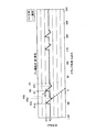
次に、気体燃料噴射弁8及びゲート弁22の異常検出方法について説明する。図8は、制御装置10がゲート弁22を閉じる指令信号を出力したにもかかわらず、ゲート弁22が開いている異常(開異常)を示す図である。図8において、横軸はクランク角度であり、縦軸は、気体燃料噴射弁8とゲート弁22との間の供給流路21の圧力(気体燃料噴射弁8の入口の圧力)である。
Next, an abnormality detection method for the gaseous
図7を参照して説明したように、制御装置10は、クランク角度がA1度のとき、ゲート弁22を開ける指令信号を出力し、クランク角度がA2度のとき、気体燃料噴射弁8を開ける指令信号を出力し、クランク角度がA3度のとき、気体燃料噴射弁8を閉じる指令信号を出力し、クランク角度がA4度のとき、ゲート弁22を閉じる指令信号を出力する。
As described with reference to FIG. 7, the
クランク角度A4のとき、制御装置10からゲート弁22を閉じる指令信号が出力されたにもかかわらず、ゲート弁22が閉じないと、期間T4においても、気体燃料供給源からの圧力P1の気体燃料PGが供給流路21に供給される。これにより、図8に示すように、期間T4における供給流路21の圧力は、圧力P1となる。
Even when a command signal for closing the
期間T4は、ピストン3が下死点近傍に位置する時点を含む。すなわち、期間T4は、クランク角度が180度である時点を含む。上述のように、気体燃料噴射弁8及びゲート弁22が正常に作動しているときの期間T4における供給流路21の圧力は、圧力P2である。このように、ゲート弁22が異常(開異常)なときと正常なときとで、期間T4における供給流路21の圧力は異なる。すなわち、ゲート弁22が正常なときは、期間Th(期間T4)における供給流路21の圧力は、図8中、実線で示すように、圧力P2となり、ゲート弁22が開異常なときは、期間Thにおける供給流路21の圧力は、図8中、点線で示すように、圧力P2よりも高い圧力P1となる。したがって、制御装置10は、ピストン3が下死点近傍に配置されているときの期間T4の少なくとも一部の期間Thにおける圧力センサ23の検出結果に基づいて、ゲート弁22が異常か否かを検出することができる。
The period T4 includes a time point when the
次に、制御装置10がゲート弁22を開ける指令信号を出力したにもかかわらず、ゲート弁22が閉じている異常(閉異常)について説明する。図9は、ゲート弁22が閉異常であるときの、クランク角度と供給流路21の圧力(気体燃料噴射弁8の入口の圧力)との関係を示す図である。
Next, an abnormality (closing abnormality) in which the
クランク角度A1のとき、制御装置10からゲート弁22を開ける指令信号が出力されたにもかかわらず、ゲート弁22が開かずに、クランク角度A2のとき、気体燃料噴射弁8が開くと、ゲート弁22が閉じた状態で、供給流路21の気体燃料PGは気体燃料噴射弁8から燃焼室7に噴射される。その結果、図9に示すように、クランク角度A2の時点から、供給流路21の圧力は低下する。このように、ゲート弁22が異常(閉異常)なときと正常なときとで、期間T2、期間T3、及び期間T4(期間Th)における供給流路21の圧力は異なる。すなわち、ゲート弁22が正常なときは、期間Th(期間T4)における供給流路21の圧力は、図9中、実線で示すように、圧力P2となり、ゲート弁22が閉異常なときは、期間Thにおける供給流路21の圧力は、図9中、点線で示すように、圧力P2よりも低い圧力となる。また、本例では、期間T2及び期間T3においても、ゲート弁22が閉異常なときの供給流路21の圧力は、ゲート弁22が正常なときの供給流路21の圧力よりも低くなる。したがって、制御装置10は、例えば、期間Thの圧力センサ23の検出結果に基づいて、ゲート弁22が異常か否かを検出することができる。
If the command signal for opening the
次に、制御装置10が気体燃料噴射弁8を閉じる指令信号を出力したにもかかわらず、気体燃料噴射弁8が開いている異常(開異常)について説明する。図10は、気体燃料噴射弁8が開異常であるときの、クランク角度と供給流路21の圧力(気体燃料噴射弁8の入口の圧力)との関係を示す図である。
Next, an abnormality (opening abnormality) in which the gaseous
クランク角度A3のとき、制御装置10から気体燃料噴射弁8を閉じる指令信号が出力されたにもかかわらず、気体燃料噴射弁8が閉じずに、クランク角度A4のとき、ゲート弁22が閉じると、ゲート弁22が閉じた状態で、供給流路21の気体燃料PGは気体燃料噴射弁8から燃焼室7に噴射される。その結果、図10に示すように、クランク角度A3の時点から、供給流路21の圧力は低下する。このように、気体燃料噴射弁8が異常(開異常)なときと正常なときとで、期間T3、及び期間T4(期間Th)における供給流路21の圧力は異なる。すなわち、気体燃料噴射弁8が正常なときは、期間Th(期間T4)における供給流路21の圧力は、図10中、実線で示すように、圧力P2となり、気体燃料噴射弁8が開異常なときは、期間Thにおける供給流路21の圧力は、図10中、点線で示すように、圧力P2よりも低い圧力となる。また、本例では、期間T3においても、気体燃料噴射弁8が開異常なときの供給流路21の圧力は、気体燃料噴射弁8が正常なときの供給流路21の圧力よりも低くなる。したがって、制御装置10は、例えば、期間Thの圧力センサ23の検出結果に基づいて、ゲート弁22が異常か否かを検出することができる。
When the control signal is output from the
次に、制御装置10が気体燃料噴射弁8を開ける指令信号を出力したにもかかわらず、気体燃料噴射弁8が閉じている異常(閉異常)について説明する。図11は、気体燃料噴射弁8が閉異常であるときの、クランク角度と供給流路21の圧力(気体燃料噴射弁8の入口の圧力)との関係を示す図である。
Next, an abnormality (closing abnormality) in which the gaseous
クランク角度A2のとき、制御装置10から気体燃料噴射弁8を開ける指令信号が出力されたにもかかわらず、気体燃料噴射弁8が開かないと、気体燃料噴射弁8が閉じ、ゲート弁22が開いている状態で、気体燃料供給源からの圧力P1の気体燃料PGが供給流路21に供給される。これにより、図11に示すように、期間T2、期間T3、及び期間T4(期間Th)における供給流路21の圧力は、圧力P1となる。このように、気体燃料噴射弁8が異常(閉異常)なときと正常なときとで、期間T2、期間T3、及び期間T4(期間Th)における供給流路21の圧力は異なる。すなわち、気体燃料噴射弁8が正常なときは、期間Th(期間T4)における供給流路21の圧力は、図11中、実線で示すように、圧力P2となり、気体燃料噴射弁8が閉異常なときは、期間Thにおける供給流路21の圧力は、図11中、点線で示すように、圧力P2よりも高い圧力P1となる。また、本例では、期間T2及び期間T3においても、気体燃料噴射弁8が閉異常なときの供給流路21の圧力は、気体燃料噴射弁8が正常なときの供給流路21の圧力よりも高くなる。したがって、制御装置10は、例えば、期間Thの圧力センサ23の検出結果に基づいて、ゲート弁22が異常か否かを検出することができる。
If the command signal for opening the gaseous
本実施形態において、図8に示す圧力(ゲート弁22が開異常のときの圧力)と図11に示す圧力(気体燃料噴射弁8が閉異常のときの圧力)とは、期間T2及び期間T3において異なるものの、期間T4において近似する。そのため、ゲート弁22及び気体燃料噴射弁8のどちらが異常なのかを、期間T4における圧力センサ23の検出結果に基づいて判断することが困難となる可能性がある。
In the present embodiment, the pressure shown in FIG. 8 (pressure when the
その場合、制御装置10は、圧力センサ23の検出結果と燃焼室7の圧力を検出する筒内センサ16の検出結果とに基づいて、気体燃料噴射弁8及びゲート弁22のどちらに異常が生じたかを判定してもよい。ゲート弁22が開異常のときと気体燃料噴射弁8が閉異常のときとで、燃焼室7の圧力は異なる。例えば、気体燃料噴射弁8が閉異常のとき、気体燃料噴射弁8から燃焼室7に気体燃料PGが噴射されないため、燃焼室7において失火が生じる可能性が高くなる。一方、ゲート弁22が開異常のとき、ゲート弁22及び気体燃料噴射弁8を介して燃焼室7に気体燃料PGが供給されるため、燃焼室7において失火が生じる可能性は低い。このように、ゲート弁22が開異常のときと気体燃料噴射弁8が閉異常のときとで、燃焼室7の異常の種類は異なる可能性が高い。また、上述したように、燃焼室7の異常の種類によって、燃焼室7の圧力は異なる。そのため、気体燃料噴射弁8に異常が生じたときの圧力センサ23の検出結果と、ゲート弁22に異常が生じたときの圧力センサ23の検出結果とが近似する場合、筒内センサ16による燃焼室7の圧力の検出結果に基づいて、気体燃料噴射弁8及びゲート弁22のどちらに異常が生じたかを判定することができる。
In that case, the
上述のように、燃焼室7の異常の種類とその異常の種類に対応する燃焼室7の圧力との関係が記憶装置に記憶されている。制御装置10は、筒内センサ16の検出結果と、記憶装置の記憶情報とに基づいて、気体燃料噴射弁8及びゲート弁22のどちらに異常が生じたかを判定することができる。
As described above, the relationship between the type of abnormality in the
また、図9に示す圧力(ゲート弁22が閉異常のときの圧力)と図10に示す圧力(気体燃料噴射弁8が開異常のときの圧力)とは、期間T2において異なるものの、期間T4において近似する。そのため、ゲート弁22及び気体燃料噴射弁8のどちらが異常なのかを、期間T4における圧力センサ23の検出結果に基づいて判断することが困難となる可能性がある。
Further, although the pressure shown in FIG. 9 (pressure when the
その場合においても、ゲート弁22が閉異常のときと気体燃料噴射弁8が開異常のときとで、燃焼室7の異常の種類は異なり、燃焼室7の圧力は異なる。例えば、ゲート弁22が閉異常のとき、ゲート弁22から気体燃料噴射弁8に気体燃料PGが供給されないため、燃焼室7において失火が生じる可能性は高くなる。一方、気体燃料噴射弁8が開異常のとき、気体燃料噴射弁8から燃焼室7に気体燃料PGが噴射されるため、燃焼室7において失火が生じる可能性は低い。そのため、制御装置10は、筒内センサ16の検出結果と、記憶装置の記憶情報とに基づいて、気体燃料噴射弁8及びゲート弁22のどちらに異常が生じたかを判定することができる。
Even in that case, the type of abnormality in the
以上説明したように、本実施形態によれば、気体燃料噴射弁8とゲート弁22との間の供給流路21の圧力の検出結果と、クランク角度の検出結果とに基づいて、気体燃料噴射弁8の異常及びゲート弁22の異常の少なくとも一方を検出することができる。したがって、例えば、その異常を解消するための適切な措置を講ずることができる。また、異常が生じている気体燃料供給システム15を使用し続けてしまう不都合を防止できる。
As described above, according to the present embodiment, the gaseous fuel injection is performed based on the detection result of the pressure in the supply passage 21 between the gaseous
また、本実施形態において、ゲート弁22は、安全弁(インターロック機構)として機能し、気体燃料PGを噴射するためにピストン3が上死点の近傍に配置されるときに作動する。気体燃料噴射弁8は、ゲート弁22が開いている状態で作動するため、気体燃料噴射弁8から燃焼室7に適切なタイミングで気体燃料PGが噴射される。ピストン3が上死点の近傍に配置されている状態で気体燃料噴射弁8及びゲート弁22が作動するため、ピストン3が下死点近傍に配置されているときの期間Thにおける圧力センサ23の検出結果に基づいて、気体燃料噴射弁8及びゲート弁22の少なくとも一方の異常を円滑に検出することができる。
In the present embodiment, the
また、本実施形態においては、期間Thにおける、気体燃料噴射弁8に異常が生じたときの圧力センサ23の検出結果と、ゲート弁22に異常が生じたときの圧力センサ23の検出結果とが近似する場合でも、筒内センサ16の検出結果を参照することにより、気体燃料噴射弁8及びゲート弁22のどちらに異常が生じたかを判定することができる。
In the present embodiment, the detection result of the
なお、本実施形態において、例えば、燃焼室7から排気ポート12を介して排出される気体(排気ガス)の温度を検出可能な温度センサを設け、その温度センサの検出結果と圧力センサ23の検出結果とに基づいて、気体燃料噴射弁8及びゲート弁22のどちらに異常が生じたかを判定してもよい。期間Thにおける、気体燃料噴射弁8に異常が生じたときの圧力センサ23の検出結果と、ゲート弁22に異常が生じたときの圧力センサ23の検出結果とが近似する場合でも、その温度センサの検出結果を参照することにより、気体燃料噴射弁8及びゲート弁22のどちらに異常が生じたかを判定することができる。
In the present embodiment, for example, a temperature sensor capable of detecting the temperature of gas (exhaust gas) discharged from the
燃焼室7の異常の種類によって、排気ポート12から排出される排気ガスの温度は異なる。そのため、気体燃料噴射弁8に異常が生じたときの圧力センサ23の検出結果と、ゲート弁22に異常が生じたときの圧力センサ23の検出結果とが近似する場合、温度センサによる排気ガスの温度の検出結果に基づいて、気体燃料噴射弁8及びゲート弁22のどちらに異常が生じたかを判定することができる。燃焼室7の異常の種類とその異常の種類に対応する排気ガスの温度との関係を記憶装置に記憶しておくことにより、制御装置10は、温度センサの検出結果と、記憶装置の記憶情報とに基づいて、気体燃料噴射弁8及びゲート弁22のどちらに異常が生じたかを判定することができる。
The temperature of the exhaust gas discharged from the exhaust port 12 varies depending on the type of abnormality in the
<第2実施形態>
第2実施形態について説明する。以下の実施形態において、上述の実施形態と同一又は同等の構成部分については同一の符号を付し、その説明を簡略又は省略する。
Second Embodiment
A second embodiment will be described. In the following embodiments, the same or equivalent components as those in the above-described embodiment are denoted by the same reference numerals, and the description thereof is simplified or omitted.
本実施形態においては、燃料油専用モードにおける圧力センサ23の検出結果に基づいて、気体燃料噴射弁8の異常を検出する例について説明する。燃料油専用モードにおいて、気体燃料供給源から気体燃料PGは供給されず、制御装置10は、気体燃料噴射弁8を閉じるように指令信号を出力する。燃料油専用モードにおいて、気体燃料噴射弁8が正常に作動するとき、気体燃料噴射弁8は閉じ、気体燃料噴射弁8から気体燃料PGは噴射されない。
In the present embodiment, an example in which an abnormality of the gaseous
制御装置10が気体燃料噴射弁8を閉じる指令信号を出力したにもかかわらず、気体燃料噴射弁8が開いている異常(開異常)が生じた場合、圧力センサ23の検出結果に基づいて、その気体燃料噴射弁8の異常を検出することができる。
Even if the
図12は、燃料油専用モードにおいて気体燃料噴射弁8が正常及び開異常であるときの、クランク角度と供給流路21の圧力(気体燃料噴射弁8の入口の圧力)との関係を示す図である。図12において、横軸はクランク角度であり、縦軸は、気体燃料噴射弁8とゲート弁22との間の供給流路21の圧力(気体燃料噴射弁8の入口の圧力)である。
FIG. 12 is a diagram showing the relationship between the crank angle and the pressure of the supply passage 21 (the pressure at the inlet of the gaseous fuel injection valve 8) when the gaseous
燃料油専用モードにおいて気体燃料噴射弁8が正常である場合、圧力センサ23の出力は一定である。一方、燃料油専用モードにおいて気体燃料噴射弁8が異常である場合(開いている場合)、燃焼室7の高温高圧の気体が気体燃料噴射弁8から供給流路21に流入する。これにより、供給流路21の圧力が上昇する。供給流路21の圧力は、圧力センサ23に検出される。そのため、制御装置10は、圧力センサ23の検出結果に基づいて、燃料油専用モードにおいて気体燃料噴射弁8に異常が生じたか否かを検出することができる。
When the gaseous
以上説明したように、本実施形態によれば、気体燃料噴射弁8が使用されない燃料油専用モードにおいても、気体燃料噴射弁8の異常を検出することができる。
As described above, according to the present embodiment, an abnormality of the gaseous
<第3実施形態>
第3実施形態について説明する。以下の実施形態において、上述の実施形態と同一又は同等の構成部分については同一の符号を付し、その説明を簡略又は省略する。
<Third Embodiment>
A third embodiment will be described. In the following embodiments, the same or equivalent components as those in the above-described embodiment are denoted by the same reference numerals, and the description thereof is simplified or omitted.
図13は、本実施形態に係る気体燃料供給システム15の一例を示す模式図である。図13に示すように、気体燃料供給システム15は、燃焼室7に気体燃料PGを噴射する気体燃料噴射弁8と、プレ噴射弁30とを備えている。プレ噴射弁30は、制御装置10に制御される。プレ噴射弁30は、気体燃料PGを燃焼室7に噴射する。
FIG. 13 is a schematic diagram illustrating an example of a gaseous
プレ噴射弁30は、気体燃料噴射弁8からの気体燃料PGの噴射前に、気体燃料PGを燃焼室7に噴射する。本実施形態においては、プレ噴射弁30から噴射された気体燃料PGにより、燃焼室7において、まず空気と気体燃料PGとの混合気体が生成された後、さらに気体燃料噴射弁8から気体燃料PGが噴射されることにより、燃焼室7において燃焼が行われる。
The
図14は、部分予混合燃焼を行う部分予混合燃焼モードのクランク角度と供給流路21の圧力(気体燃料噴射弁8の入口の圧力)との関係を示す図である。図14において、横軸はクランク角度であり、縦軸は、気体燃料噴射弁8とゲート弁22との間の供給流路21の圧力(気体燃料噴射弁8の入口の圧力)である。また、図14は、プレ噴射弁30が正常及び開異常であるときの、クランク角度と供給流路21の圧力との関係を示す。
FIG. 14 is a diagram showing the relationship between the crank angle in the partial premixed combustion mode in which the partial premixed combustion is performed and the pressure of the supply flow path 21 (pressure at the inlet of the gaseous fuel injection valve 8). In FIG. 14, the horizontal axis is the crank angle, and the vertical axis is the pressure in the supply passage 21 between the gaseous
部分予混合燃焼モードにおいては、気体燃料噴射弁8からの気体燃料PGの噴射が行われる前に、プレ噴射弁30からの気体燃料PGの噴射が行われる。気体燃料噴射弁8から気体燃料PGを噴射するときの気体燃料噴射弁8及びゲート弁22の動作は、上述の実施形態と同様である。すなわち、制御装置10は、クランク角度がA1度のとき、ゲート弁22を開け、クランク角度がA2度のとき、気体燃料噴射弁8を開け、クランク角度がA3度のとき、気体燃料噴射弁8を閉じ、クランク角度がA4度のとき、ゲート弁22を閉じるように指令信号を出力する。
In the partial premixed combustion mode, the gaseous fuel PG is injected from the
プレ噴射弁30から気体燃料PGを噴射するときのゲート弁22及びプレ噴射弁30の開閉のシーケンスは、気体燃料噴射弁8から気体燃料PGを噴射するときのゲート弁22及び気体燃料噴射弁8の開閉のシーケンスと同様である。すなわち、プレ噴射弁30から気体燃料PGを噴射するとき、制御装置10は、クランク角度がA1p度のとき、ゲート弁22を開け、クランク角度がA2p度のとき、プレ噴射弁30を開け、クランク角度がA3p度のとき、プレ噴射弁30を閉じ、クランク角度がA4p度のとき、プレ噴射弁30を閉じる。
The sequence of opening and closing the
制御装置10は、クランク角度A3pにおいて気体燃料PGを噴射したプレ噴射弁30を閉じてからクランク角度A4pにおいてゲート弁22を閉じた後、気体燃料噴射弁8からの気体燃料PGの噴射が行われるように、クランク角度A1においてゲート弁22を開けるように指令信号を出力する。
The
図14を参照して、制御装置10がプレ噴射弁30を閉じる指令信号を出力したにもかかわらず、プレ噴射弁30が開いている異常(開異常)について説明する。
With reference to FIG. 14, an abnormality (open abnormality) in which the
クランク角度A3pのとき、制御装置10からプレ噴射弁30を閉じる指令信号が出力されたにもかかわらず、プレ噴射弁30が閉じずに、クランク角度A4pのとき、ゲート弁22が閉じると、ゲート弁22が閉じた状態で、気体燃料PGはプレ噴射弁30から燃焼室7に噴射される。その結果、図14に示すように、クランク角度A3pの時点から、供給流路21の圧力は低下する。このように、プレ噴射弁30が異常(開異常)なときと正常なときとで、クランク角度A3pにおいてプレ噴射弁30を閉じるための指令信号が出力されてからクランク角度A1においてゲート弁22を開くための指令信号が出力されるまでの期間Tjにおける供給流路21の圧力は異なる。すなわち、プレ噴射弁30が正常なときは、期間Tjにおける供給流路21の圧力は、図14中、実線で示すように、圧力P2となり、プレ噴射弁30が開異常なときは、期間Tjにおける供給流路21の圧力は、図14中、点線で示すように、圧力P2よりも低い圧力となる。したがって、制御装置10は、期間Tjにおける圧力センサ23の検出結果に基づいて、プレ噴射弁30が異常か否かを検出することができる。
Even if the command signal for closing the
次に、制御装置10がプレ噴射弁30を開ける指令信号を出力したにもかかわらず、プレ噴射弁30が閉じている異常(閉異常)について説明する。図15は、プレ噴射弁30が閉異常であるときの、クランク角度と供給流路21の圧力(気体燃料噴射弁8の入口の圧力)との関係を示す図である。
Next, an abnormality (closing abnormality) in which the
クランク角度A2pのとき、制御装置10からプレ噴射弁30を開く指令信号が出力されたにもかかわらず、プレ噴射弁30が開かないと、プレ噴射弁30が閉じ、ゲート弁22が開いている状態で、圧力P1の気体燃料PGが供給流路21に供給される。これにより、図15に示すように、期間Tjにおける供給流路21の圧力は、圧力P1となる。このように、プレ噴射弁30が異常(閉異常)なときと正常なときとで、期間Tjにおける供給流路21の圧力は異なる。すなわち、プレ噴射弁30が正常なときは、期間Tjにおける供給流路21の圧力は、図15中、実線で示すように、圧力P2となり、プレ噴射弁30が閉異常なときは、期間Tjにおける供給流路21の圧力は、図15中、点線で示すように、圧力P2よりも高い圧力P1となる。したがって、期間Tjにおける圧力センサ23の検出結果に基づいて、プレ噴射弁30が異常か否かを検出することができる。
When the crank angle is A2p, a command signal for opening the
以上説明したように、本実施形態によれば、気体燃料供給システム15がプレ噴射弁30を有する場合、プレ噴射弁30が閉じてからゲート弁22が開くまでの期間Tjにおける圧力センサ23の検出結果に基づいてプレ噴射弁30の異常を検出することができる。
As described above, according to the present embodiment, when the gaseous
1 デュアルフューエルエンジン
7 燃焼室
8 気体燃料噴射弁
15 気体燃料供給システム
16 筒内センサ
21 供給流路
22 ゲート弁
23 圧力センサ
30 プレ噴射弁
PG 気体燃料
DESCRIPTION OF
Claims (8)
前記燃焼室に前記気体燃料を噴射する噴射弁と、
第1圧力の前記気体燃料を供給する気体燃料供給源と、
前記気体燃料供給源から前記噴射弁に供給される前記気体燃料が流れる供給流路と、
前記供給流路を開閉可能なゲート弁と、
前記噴射弁と前記ゲート弁との間の前記供給流路の圧力を検出する圧力センサと、
前記噴射弁及び前記ゲート弁を開閉する指令信号を出力する制御装置と、を備え、
前記制御装置は、前記エンジンのクランク軸のクランク角度を検出する検出装置の検出結果に基づいて、前記クランク角度が前記エンジンのピストンが上死点近傍に位置する第1角度になったときに前記ゲート弁を開ける指令信号を出力し、前記クランク角度が第2角度になったときに前記噴射弁を開ける指令信号を出力し、前記クランク角度が前記第2角度よりも大きい第3角度になったときに前記噴射弁を閉じる指令信号を出力し、前記クランク角度が前記第3角度よりも大きい第4角度になったときに前記供給流路の圧力を前記第1圧力よりも低い第2圧力にするために前記ゲート弁を閉じる指令信号を出力し、
前記圧力センサの検出結果と前記エンジンのクランク軸のクランク角度を検出する検出装置の検出結果とに基づいて、
前記クランク角度が前記第2角度になったときから前記第3角度になるまでの第2期間、前記第3角度になったときから前記第4角度になるまでの第3期間、及び前記第3期間の後の前記ピストンが下死点近傍に位置する時点を含む第4期間のうち、前記第4期間における前記圧力センサの検出結果が前記噴射弁及び前記ゲート弁が正常に作動しているときの前記供給流路の圧力よりも高いとき、前記ゲート弁の開異常を検出する、
気体燃料供給システム。 A gaseous fuel supply system for supplying gaseous fuel to a combustion chamber of an engine,
An injection valve for injecting the gaseous fuel into the combustion chamber;
A gaseous fuel supply source for supplying the gaseous fuel at a first pressure;
A supply flow path through which the gaseous fuel supplied from the gaseous fuel supply source to the injection valve flows;
A gate valve capable of opening and closing the supply flow path;
A pressure sensor for detecting the pressure of the supply flow path between the injection valve and the gate valve;
A control device for outputting a command signal for opening and closing the injection valve and the gate valve,
When the crank angle becomes a first angle at which the piston of the engine is located near top dead center based on a detection result of a detection device that detects a crank angle of the crankshaft of the engine, A command signal for opening the gate valve is output, and a command signal for opening the injection valve is output when the crank angle reaches the second angle, and the crank angle becomes a third angle larger than the second angle. A command signal for closing the injection valve is sometimes output, and when the crank angle becomes a fourth angle larger than the third angle, the pressure of the supply passage is set to a second pressure lower than the first pressure. In order to output a command signal to close the gate valve,
Based on the detection result of the pressure sensor and the detection result of the detection device for detecting the crank angle of the crankshaft of the engine,
A second period from when the crank angle reaches the second angle to the third angle, a third period from when the crank angle reaches the fourth angle, and the third angle The detection result of the pressure sensor in the fourth period of the fourth period including the time point when the piston after the period is located near the bottom dead center is when the injection valve and the gate valve are operating normally When the pressure of the supply flow path is higher than that, the abnormal opening of the gate valve is detected.
Gaseous fuel supply system.
前記燃焼室に前記気体燃料を噴射する噴射弁と、
第1圧力の前記気体燃料を供給する気体燃料供給源と、
前記気体燃料供給源から前記噴射弁に供給される前記気体燃料が流れる供給流路と、
前記供給流路を開閉可能なゲート弁と、
前記噴射弁と前記ゲート弁との間の前記供給流路の圧力を検出する圧力センサと、
前記噴射弁及び前記ゲート弁を開閉する指令信号を出力する制御装置と、を備え、
前記制御装置は、前記エンジンのクランク軸のクランク角度を検出する検出装置の検出結果に基づいて、前記クランク角度が前記エンジンのピストンが上死点近傍に位置する第1角度になったときに前記ゲート弁を開ける指令信号を出力し、前記クランク角度が第2角度になったときに前記噴射弁を開ける指令信号を出力し、前記クランク角度が前記第2角度よりも大きい第3角度になったときに前記噴射弁を閉じる指令信号を出力し、前記クランク角度が前記第3角度よりも大きい第4角度になったときに前記供給流路の圧力を前記第1圧力よりも低い第2圧力にするために前記ゲート弁を閉じる指令信号を出力し、
前記圧力センサの検出結果と前記エンジンのクランク軸のクランク角度を検出する検出装置の検出結果とに基づいて、
前記クランク角度が前記第2角度になったときから前記第3角度になるまでの第2期間、前記第3角度になったときから前記第4角度になるまでの第3期間、及び前記第3期間の後の前記ピストンが下死点近傍に位置する時点を含む第4期間のうち、前記第2期間、前記第3期間、及び前記第4期間における前記圧力センサの検出結果が前記噴射弁及び前記ゲート弁が正常に作動しているときの前記供給流路の圧力よりも低いとき、前記ゲート弁の閉異常を検出する、
気体燃料供給システム。 A gaseous fuel supply system for supplying gaseous fuel to a combustion chamber of an engine,
An injection valve for injecting the gaseous fuel into the combustion chamber;
A gaseous fuel supply source for supplying the gaseous fuel at a first pressure;
A supply flow path through which the gaseous fuel supplied from the gaseous fuel supply source to the injection valve flows;
A gate valve capable of opening and closing the supply flow path;
A pressure sensor for detecting the pressure of the supply flow path between the injection valve and the gate valve;
A control device for outputting a command signal for opening and closing the injection valve and the gate valve,
When the crank angle becomes a first angle at which the piston of the engine is located near top dead center based on a detection result of a detection device that detects a crank angle of the crankshaft of the engine, A command signal for opening the gate valve is output, and a command signal for opening the injection valve is output when the crank angle reaches the second angle, and the crank angle becomes a third angle larger than the second angle. A command signal for closing the injection valve is sometimes output, and when the crank angle becomes a fourth angle larger than the third angle, the pressure of the supply passage is set to a second pressure lower than the first pressure. In order to output a command signal to close the gate valve,
Based on the detection result of the pressure sensor and the detection result of the detection device for detecting the crank angle of the crankshaft of the engine,
A second period from when the crank angle reaches the second angle to the third angle, a third period from when the crank angle reaches the fourth angle, and the third angle Among the fourth period including the time point at which the piston after the period is located near the bottom dead center , the detection result of the pressure sensor in the second period, the third period, and the fourth period is the injection valve and Detecting a closing abnormality of the gate valve when lower than the pressure of the supply flow path when the gate valve is operating normally;
Gaseous fuel supply system.
前記燃焼室に前記気体燃料を噴射する噴射弁と、
第1圧力の前記気体燃料を供給する気体燃料供給源と、
前記気体燃料供給源から前記噴射弁に供給される前記気体燃料が流れる供給流路と、
前記供給流路を開閉可能なゲート弁と、
前記噴射弁と前記ゲート弁との間の前記供給流路の圧力を検出する圧力センサと、
前記噴射弁及び前記ゲート弁を開閉する指令信号を出力する制御装置と、を備え、
前記制御装置は、前記エンジンのクランク軸のクランク角度を検出する検出装置の検出結果に基づいて、前記クランク角度が前記エンジンのピストンが上死点近傍に位置する第1角度になったときに前記ゲート弁を開ける指令信号を出力し、前記クランク角度が第2角度になったときに前記噴射弁を開ける指令信号を出力し、前記クランク角度が前記第2角度よりも大きい第3角度になったときに前記噴射弁を閉じる指令信号を出力し、前記クランク角度が前記第3角度よりも大きい第4角度になったときに前記供給流路の圧力を前記第1圧力よりも低い第2圧力にするために前記ゲート弁を閉じる指令信号を出力し、
前記圧力センサの検出結果と前記エンジンのクランク軸のクランク角度を検出する検出装置の検出結果とに基づいて、
前記クランク角度が前記第2角度になったときから前記第3角度になるまでの第2期間、前記第3角度になったときから前記第4角度になるまでの第3期間、及び前記第3期間の後の前記ピストンが下死点近傍に位置する時点を含む第4期間のうち、前記第3期間及び前記第4期間における前記圧力センサの検出結果が前記噴射弁及び前記ゲート弁が正常に作動しているときの前記供給流路の圧力よりも低いとき、前記噴射弁の開異常を検出する、
気体燃料供給システム。 A gaseous fuel supply system for supplying gaseous fuel to a combustion chamber of an engine,
An injection valve for injecting the gaseous fuel into the combustion chamber;
A gaseous fuel supply source for supplying the gaseous fuel at a first pressure;
A supply flow path through which the gaseous fuel supplied from the gaseous fuel supply source to the injection valve flows;
A gate valve capable of opening and closing the supply flow path;
A pressure sensor for detecting the pressure of the supply flow path between the injection valve and the gate valve;
A control device for outputting a command signal for opening and closing the injection valve and the gate valve,
When the crank angle becomes a first angle at which the piston of the engine is located near top dead center based on a detection result of a detection device that detects a crank angle of the crankshaft of the engine, A command signal for opening the gate valve is output, and a command signal for opening the injection valve is output when the crank angle reaches the second angle, and the crank angle becomes a third angle larger than the second angle. A command signal for closing the injection valve is sometimes output, and when the crank angle becomes a fourth angle larger than the third angle, the pressure of the supply passage is set to a second pressure lower than the first pressure. In order to output a command signal to close the gate valve,
Based on the detection result of the pressure sensor and the detection result of the detection device for detecting the crank angle of the crankshaft of the engine,
A second period from when the crank angle reaches the second angle to the third angle, a third period from when the crank angle reaches the fourth angle, and the third angle Among the fourth period including the time point when the piston after the period is located near the bottom dead center , the detection results of the pressure sensor in the third period and the fourth period indicate that the injection valve and the gate valve are normal. Detecting an opening abnormality of the injection valve when lower than the pressure of the supply flow path when operating ;
Gaseous fuel supply system.
前記燃焼室に前記気体燃料を噴射する噴射弁と、
第1圧力の前記気体燃料を供給する気体燃料供給源と、
前記気体燃料供給源から前記噴射弁に供給される前記気体燃料が流れる供給流路と、
前記供給流路を開閉可能なゲート弁と、
前記噴射弁と前記ゲート弁との間の前記供給流路の圧力を検出する圧力センサと、
前記噴射弁及び前記ゲート弁を開閉する指令信号を出力する制御装置と、を備え、
前記制御装置は、前記エンジンのクランク軸のクランク角度を検出する検出装置の検出結果に基づいて、前記クランク角度が前記エンジンのピストンが上死点近傍に位置する第1角度になったときに前記ゲート弁を開ける指令信号を出力し、前記クランク角度が第2角度になったときに前記噴射弁を開ける指令信号を出力し、前記クランク角度が前記第2角度よりも大きい第3角度になったときに前記噴射弁を閉じる指令信号を出力し、前記クランク角度が前記第3角度よりも大きい第4角度になったときに前記供給流路の圧力を前記第1圧力よりも低い第2圧力にするために前記ゲート弁を閉じる指令信号を出力し、
前記圧力センサの検出結果と前記エンジンのクランク軸のクランク角度を検出する検出装置の検出結果とに基づいて、
前記クランク角度が前記第2角度になったときから前記第3角度になるまでの第2期間、前記第3角度になったときから前記第4角度になるまでの第3期間、及び前記第3期間の後の前記ピストンが下死点近傍に位置する時点を含む第4期間のうち、前記第2期間、前記第3期間、及び前記第4期間における前記圧力センサの検出結果が前記噴射弁及び前記ゲート弁が正常に作動しているときの前記供給流路の圧力よりも高いとき、前記噴射弁の閉異常を検出する、
気体燃料供給システム。 A gaseous fuel supply system for supplying gaseous fuel to a combustion chamber of an engine,
An injection valve for injecting the gaseous fuel into the combustion chamber;
A gaseous fuel supply source for supplying the gaseous fuel at a first pressure;
A supply flow path through which the gaseous fuel supplied from the gaseous fuel supply source to the injection valve flows;
A gate valve capable of opening and closing the supply flow path;
A pressure sensor for detecting the pressure of the supply flow path between the injection valve and the gate valve;
A control device for outputting a command signal for opening and closing the injection valve and the gate valve,
When the crank angle becomes a first angle at which the piston of the engine is located near top dead center based on a detection result of a detection device that detects a crank angle of the crankshaft of the engine, A command signal for opening the gate valve is output, and a command signal for opening the injection valve is output when the crank angle reaches the second angle, and the crank angle becomes a third angle larger than the second angle. A command signal for closing the injection valve is sometimes output, and when the crank angle becomes a fourth angle larger than the third angle, the pressure of the supply passage is set to a second pressure lower than the first pressure. In order to output a command signal to close the gate valve,
Based on the detection result of the pressure sensor and the detection result of the detection device for detecting the crank angle of the crankshaft of the engine,
A second period from when the crank angle reaches the second angle to the third angle, a third period from when the crank angle reaches the fourth angle, and the third angle Among the fourth period including the time point at which the piston after the period is located near the bottom dead center , the detection result of the pressure sensor in the second period, the third period, and the fourth period is the injection valve and Detecting a closing abnormality of the injection valve when higher than the pressure of the supply flow path when the gate valve is operating normally;
Gaseous fuel supply system.
前記燃焼室に前記気体燃料を噴射する噴射弁と、
第1圧力の前記気体燃料を供給する気体燃料供給源と、
前記気体燃料供給源から前記噴射弁に供給される前記気体燃料が流れる供給流路と、
前記供給流路を開閉可能なゲート弁と、
前記噴射弁と前記ゲート弁との間の前記供給流路の圧力を検出する圧力センサと、
前記噴射弁及び前記ゲート弁を開閉する指令信号を出力する制御装置と、を備え、
前記制御装置は、前記エンジンのクランク軸のクランク角度を検出する検出装置の検出結果に基づいて、前記クランク角度が前記エンジンのピストンが上死点近傍に位置する第1角度になったときに前記ゲート弁を開ける指令信号を出力し、前記クランク角度が第2角度になったときに前記噴射弁を開ける指令信号を出力し、前記クランク角度が前記第2角度よりも大きい第3角度になったときに前記噴射弁を閉じる指令信号を出力し、前記クランク角度が前記第3角度よりも大きい第4角度になったときに前記供給流路の圧力を前記第1圧力よりも低い第2圧力にするために前記ゲート弁を閉じる指令信号を出力し、
前記圧力センサの検出結果と前記エンジンのクランク軸のクランク角度を検出する検出装置の検出結果とに基づいて、
前記クランク角度が前記第2角度になったときから前記第3角度になるまでの第2期間、前記第3角度になったときから前記第4角度になるまでの第3期間、及び前記第3期間の後の前記ピストンが下死点近傍に位置する時点を含む第4期間のうち、前記第4期間における前記圧力センサの検出結果が前記噴射弁及び前記ゲート弁が正常に作動しているときの前記供給流路の圧力よりも高いとき、前記ゲート弁の開異常を検出し、
前記第2期間、前記第3期間、及び前記第4期間における前記圧力センサの検出結果が前記噴射弁及び前記ゲート弁が正常に作動しているときの前記供給流路の圧力よりも高いとき、前記噴射弁の閉異常を検出し、
前記圧力センサの検出結果と前記燃焼室の圧力を検出する筒内センサの検出結果とに基づいて、前記ゲート弁の開異常及び前記噴射弁の閉異常のどちらが生じたかを判定する、
気体燃料供給システム。 A gaseous fuel supply system for supplying gaseous fuel to a combustion chamber of an engine,
An injection valve for injecting the gaseous fuel into the combustion chamber;
A gaseous fuel supply source for supplying the gaseous fuel at a first pressure;
A supply flow path through which the gaseous fuel supplied from the gaseous fuel supply source to the injection valve flows;
A gate valve capable of opening and closing the supply flow path;
A pressure sensor for detecting the pressure of the supply flow path between the injection valve and the gate valve;
A control device for outputting a command signal for opening and closing the injection valve and the gate valve,
When the crank angle becomes a first angle at which the piston of the engine is located near top dead center based on a detection result of a detection device that detects a crank angle of the crankshaft of the engine, A command signal for opening the gate valve is output, and a command signal for opening the injection valve is output when the crank angle reaches the second angle, and the crank angle becomes a third angle larger than the second angle. A command signal for closing the injection valve is sometimes output, and when the crank angle becomes a fourth angle larger than the third angle, the pressure of the supply passage is set to a second pressure lower than the first pressure. In order to output a command signal to close the gate valve,
Based on the detection result of the pressure sensor and the detection result of the detection device for detecting the crank angle of the crankshaft of the engine,
A second period from when the crank angle reaches the second angle to the third angle, a third period from when the crank angle reaches the fourth angle, and the third angle The detection result of the pressure sensor in the fourth period of the fourth period including the time point when the piston after the period is located near the bottom dead center is when the injection valve and the gate valve are operating normally When the pressure of the supply flow path is higher, the opening abnormality of the gate valve is detected,
When the detection result of the pressure sensor in the second period, the third period, and the fourth period is higher than the pressure of the supply flow path when the injection valve and the gate valve are operating normally, Detecting an abnormal closing of the injection valve;
Based on the detection result of the pressure sensor and the detection result of an in-cylinder sensor that detects the pressure in the combustion chamber, it is determined whether an abnormality in the opening of the gate valve or an abnormality in the closing of the injection valve has occurred.
Gaseous fuel supply system.
前記燃焼室に前記気体燃料を噴射する噴射弁と、
第1圧力の前記気体燃料を供給する気体燃料供給源と、
前記気体燃料供給源から前記噴射弁に供給される前記気体燃料が流れる供給流路と、
前記供給流路を開閉可能なゲート弁と、
前記噴射弁と前記ゲート弁との間の前記供給流路の圧力を検出する圧力センサと、
前記噴射弁からの前記気体燃料の噴射前に、気体燃料を前記燃焼室に噴射するプレ噴射弁と、
前記噴射弁及び前記ゲート弁を開閉する指令信号を出力する制御装置と、を備え、
前記制御装置は、前記エンジンのクランク軸のクランク角度を検出する検出装置の検出結果に基づいて、前記クランク角度が前記エンジンのピストンが上死点近傍に位置する第1角度になったときに前記ゲート弁を開ける指令信号を出力し、前記クランク角度が第2角度になったときに前記噴射弁を開ける指令信号を出力し、前記クランク角度が前記第2角度よりも大きい第3角度になったときに前記噴射弁を閉じる指令信号を出力し、前記クランク角度が前記第3角度よりも大きい第4角度になったときに前記供給流路の圧力を前記第1圧力よりも低い第2圧力にするために前記ゲート弁を閉じる指令信号を出力し、
前記制御装置は、前記気体燃料を噴射した前記プレ噴射弁を閉じてから前記ゲート弁を閉じた後、前記噴射弁からの前記気体燃料の噴射のために前記ゲート弁を開けるように指令信号を出力し、前記プレ噴射弁を閉じるための指令信号が出力されてから前記ゲート弁を開くための指令信号が出力されるまでの期間における前記圧力センサの検出結果に基づいて、前記プレ噴射弁の異常を検出し、前記検出装置の検出結果に基づいて、前記クランク角度が第1プレ角度になったときに前記ゲート弁を開ける指令信号を出力し、前記クランク角度が前記第1プレ角度よりも大きい第2プレ角度になったときに前記プレ噴射弁を開ける指令信号を出力し、前記クランク角度が前記第2プレ角度よりも大きい第3プレ角度になったときに前記プレ噴射弁を閉じる指令信号を出力し、前記クランク角度が前記第3プレ角度よりも大きい第4プレ角度になったときに前記供給流路の圧力を前記第2圧力にするために前記ゲート弁を閉じる指令信号を出力し、前記ゲート弁を閉じた後、前記噴射弁からの前記気体燃料の噴射のために前記ゲート弁を開けるように指令信号を出力し、
前記プレ噴射弁を閉じるための指令信号が出力されてから前記ゲート弁を開くための指令信号が出力されるまでの期間における前記圧力センサの検出結果に基づいて、
前記期間における前記検出結果が前記第2圧力よりも低い圧力であるとき、前記プレ噴射弁の開異常を検出し、
前記期間における前記検出結果が前記第1圧力であるとき、前記プレ噴射弁の閉異常を検出する、
気体燃料システム。 A gaseous fuel supply system for supplying gaseous fuel to a combustion chamber of an engine,
An injection valve for injecting the gaseous fuel into the combustion chamber;
A gaseous fuel supply source for supplying the gaseous fuel at a first pressure;
A supply flow path through which the gaseous fuel supplied from the gaseous fuel supply source to the injection valve flows;
A gate valve capable of opening and closing the supply flow path;
A pressure sensor for detecting the pressure of the supply flow path between the injection valve and the gate valve;
A pre-injection valve that injects gaseous fuel into the combustion chamber before the injection of the gaseous fuel from the injection valve;
A control device for outputting a command signal for opening and closing the injection valve and the gate valve,
When the crank angle becomes a first angle at which the piston of the engine is located near top dead center based on a detection result of a detection device that detects a crank angle of the crankshaft of the engine, A command signal for opening the gate valve is output, and a command signal for opening the injection valve is output when the crank angle reaches the second angle, and the crank angle becomes a third angle larger than the second angle. A command signal for closing the injection valve is sometimes output, and when the crank angle becomes a fourth angle larger than the third angle, the pressure of the supply passage is set to a second pressure lower than the first pressure. In order to output a command signal to close the gate valve,
The control device closes the pre-injection valve that injected the gaseous fuel and then closes the gate valve, and then issues a command signal to open the gate valve for the injection of the gaseous fuel from the injection valve. Output of the pre-injection valve based on the detection result of the pressure sensor in a period from when the command signal for closing the pre-injection valve is output until the instruction signal for opening the gate valve is output. An abnormality is detected , and based on the detection result of the detection device, a command signal for opening the gate valve is output when the crank angle reaches the first pre-angle, and the crank angle is greater than the first pre-angle. A command signal for opening the pre-injection valve is output when the second pre-angle is large, and the pre-injection is performed when the crank angle is a third pre-angle larger than the second pre-angle. A command signal to close the gate valve in order to set the pressure of the supply flow path to the second pressure when the crank angle becomes a fourth pre-angle larger than the third pre-angle. Output a signal, and after closing the gate valve, output a command signal to open the gate valve for injection of the gaseous fuel from the injection valve,
Based on the detection result of the pressure sensor in the period from the output of the command signal for closing the pre-injection valve to the output of the command signal for opening the gate valve,
When the detection result in the period is a pressure lower than the second pressure, an opening abnormality of the pre-injection valve is detected,
When the detection result in the period is the first pressure, an abnormal closing of the pre-injection valve is detected.
Gas fuel system.
前記燃焼室に前記気体燃料を噴射する噴射弁と、
第1圧力の前記気体燃料を供給する気体燃料供給源と、
前記気体燃料供給源から前記噴射弁に供給される前記気体燃料が流れる供給流路と、
前記供給流路を開閉可能なゲート弁と、
前記噴射弁と前記ゲート弁との間の前記供給流路の圧力を検出する圧力センサと、
前記噴射弁及び前記ゲート弁を開閉する指令信号を出力する制御装置と、を備え、
前記デュアルフューエルエンジンは、前記燃焼室に液体燃料噴射弁から液体燃料が供給され前記気体燃料が供給される二種燃料モードと前記燃焼室に液体燃料噴射弁から液体燃料が供給され前記気体燃料が供給されない燃料油専用モードとのそれぞれで作動可能であり、
前記制御装置は、前記エンジンのクランク軸のクランク角度を検出する検出装置の検出結果に基づいて、前記クランク角度が前記エンジンのピストンが上死点近傍に位置する第1角度になったときに前記ゲート弁を開ける指令信号を出力し、前記クランク角度が第2角度になったときに前記噴射弁を開ける指令信号を出力し、前記クランク角度が前記第2角度よりも大きい第3角度になったときに前記噴射弁を閉じる指令信号を出力し、前記クランク角度が前記第3角度よりも大きい第4角度になったときに前記供給流路の圧力を前記第1圧力よりも低い第2圧力にするために前記ゲート弁を閉じる指令信号を出力し、
前記二種燃料モードにおける前記圧力センサの検出結果と前記エンジンのクランク軸のクランク角度を検出する検出装置の検出結果とに基づいて、前記噴射弁の閉異常を検出し、
前記燃料油専用モードにおける前記圧力センサの検出結果に基づいて、前記供給流路の圧力が上昇したとき、前記噴射弁の開異常を検出する、
気体燃料供給システム。 A gaseous fuel supply system that supplies gaseous fuel to a combustion chamber of an engine that is a dual fuel engine,
An injection valve for injecting the gaseous fuel into the combustion chamber;
A gaseous fuel supply source for supplying the gaseous fuel at a first pressure;
A supply flow path through which the gaseous fuel supplied from the gaseous fuel supply source to the injection valve flows;
A gate valve capable of opening and closing the supply flow path;
A pressure sensor for detecting the pressure of the supply flow path between the injection valve and the gate valve;
A control device for outputting a command signal for opening and closing the injection valve and the gate valve,
In the dual fuel engine, a liquid fuel is supplied from the liquid fuel injection valve to the combustion chamber and the gaseous fuel is supplied, and a liquid fuel is supplied from the liquid fuel injection valve to the combustion chamber and the gaseous fuel is supplied to the combustion chamber. Can operate in each mode with fuel oil only mode not supplied,
When the crank angle becomes a first angle at which the piston of the engine is located near top dead center based on a detection result of a detection device that detects a crank angle of the crankshaft of the engine, A command signal for opening the gate valve is output, and a command signal for opening the injection valve is output when the crank angle reaches the second angle, and the crank angle becomes a third angle larger than the second angle. A command signal for closing the injection valve is sometimes output, and when the crank angle becomes a fourth angle larger than the third angle, the pressure of the supply passage is set to a second pressure lower than the first pressure. In order to output a command signal to close the gate valve,
Based on a detection result of the pressure sensor in the two-fuel mode and a detection result of a detection device that detects a crank angle of the crankshaft of the engine, a closing abnormality of the injection valve is detected,
Based on the detection result of the pressure sensor in the fuel oil-only mode, when the pressure of the supply flow path increases, an abnormal opening of the injection valve is detected.
Gaseous fuel supply system.
前記気体燃料供給システムは、
前記燃焼室に前記気体燃料を噴射する噴射弁と、
第1圧力の前記気体燃料を供給する気体燃料供給源と、
前記気体燃料供給源から前記噴射弁に供給される前記気体燃料が流れる供給流路と、
前記供給流路を開閉可能なゲート弁と、
前記噴射弁と前記ゲート弁との間の前記供給流路の圧力を検出する圧力センサと、を備え、
前記エンジンのクランク軸のクランク角度を検出する検出装置の検出結果に基づいて、前記クランク角度が前記エンジンのピストンが上死点近傍に位置する第1角度になったときに前記ゲート弁を開ける指令信号を出力する工程と、
前記クランク角度が第2角度になったときに前記噴射弁を開ける指令信号を出力する工程と、
前記クランク角度が前記第2角度よりも大きい第3角度になったときに前記噴射弁を閉じる指令信号を出力する工程と、
前記クランク角度が前記第3角度よりも大きい第4角度になったときに前記供給流路の圧力を前記第1圧力よりも低い第2圧力にするために前記ゲート弁を閉じる指令信号を出力する工程と、
前記圧力センサの検出結果と前記エンジンのクランク軸のクランク角度を検出する検出装置の検出結果とに基づいて、前記クランク角度が前記第2角度になったときから前記第3角度になるまでの第2期間、前記第3角度になったときから前記第4角度になるまでの第3期間、及び前記第3期間の後の前記ピストンが下死点近傍に位置する時点を含む第4期間のうち、前記第4期間における前記圧力センサの検出結果が前記噴射弁及び前記ゲート弁が正常に作動しているときの前記供給流路の圧力よりも高いとき、前記ゲート弁の開異常を検出する工程と、
前記第2期間、前記第3期間、及び前記第4期間における前記圧力センサの検出結果が前記噴射弁及び前記ゲート弁が正常に作動しているときの前記供給流路の圧力よりも低いとき、前記ゲート弁の閉異常を検出する工程と、
前記第3期間及び前記第4期間における前記圧力センサの検出結果が前記噴射弁及び前記ゲート弁が正常に作動しているときの前記供給流路の圧力よりも低いとき、前記噴射弁の開異常を検出する工程と、
前記第2期間、前記第3期間、及び前記第4期間における前記圧力センサの検出結果が前記噴射弁及び前記ゲート弁が正常に作動しているときの前記供給流路の圧力よりも高いとき、前記噴射弁の閉異常を検出する工程と、
を含む気体燃料供給システムの異常検出方法。 An abnormality detection method for a gaseous fuel supply system for supplying gaseous fuel to a combustion chamber of an engine,
The gaseous fuel supply system includes:
An injection valve for injecting the gaseous fuel into the combustion chamber;
A gaseous fuel supply source for supplying the gaseous fuel at a first pressure;
A supply flow path through which the gaseous fuel supplied from the gaseous fuel supply source to the injection valve flows;
A gate valve capable of opening and closing the supply flow path;
A pressure sensor for detecting the pressure of the supply flow path between the injection valve and the gate valve,
Based on the detection result of the detection device for detecting the crank angle of the crankshaft of the engine, a command to open the gate valve when the crank angle becomes the first angle at which the piston of the engine is located near top dead center Outputting a signal;
Outputting a command signal for opening the injection valve when the crank angle becomes the second angle;
Outputting a command signal for closing the injection valve when the crank angle becomes a third angle larger than the second angle;
When the crank angle becomes a fourth angle larger than the third angle, a command signal for closing the gate valve is output in order to set the pressure of the supply flow path to a second pressure lower than the first pressure. Process,
Based on the detection result of the pressure sensor and the detection result of the detection device for detecting the crank angle of the crankshaft of the engine, a first time from when the crank angle becomes the second angle until the third angle is reached. 2 periods, a third period from when the third angle is reached until the fourth angle is reached, and a fourth period including a time point at which the piston after the third period is located near the bottom dead center Detecting an abnormal opening of the gate valve when the detection result of the pressure sensor in the fourth period is higher than the pressure of the supply flow path when the injection valve and the gate valve are operating normally. When,
When the detection result of the pressure sensor in the second period, the third period, and the fourth period is lower than the pressure of the supply flow path when the injection valve and the gate valve are operating normally, Detecting a closing abnormality of the gate valve;
When the detection result of the pressure sensor in the third period and the fourth period is lower than the pressure in the supply flow path when the injection valve and the gate valve are operating normally, the abnormal opening of the injection valve Detecting
When the detection result of the pressure sensor in the second period, the third period, and the fourth period is higher than the pressure of the supply flow path when the injection valve and the gate valve are operating normally, Detecting an abnormal closing of the injection valve;
An abnormality detection method for a gaseous fuel supply system including:
Priority Applications (4)
| Application Number | Priority Date | Filing Date | Title |
|---|---|---|---|
| JP2013270058A JP6373578B2 (en) | 2013-12-26 | 2013-12-26 | Gaseous fuel supply system and abnormality detection method for gaseous fuel supply system |
| PCT/JP2014/083025 WO2015098578A1 (en) | 2013-12-26 | 2014-12-12 | Gas fuel supply system and method for detecting abnormality of gas fuel supply system |
| CN201480059078.9A CN105849395B (en) | 2013-12-26 | 2014-12-12 | The method for detecting abnormality of gas fuel supply system and gas fuel supply system |
| KR1020167010947A KR101864971B1 (en) | 2013-12-26 | 2014-12-12 | Gas fuel supply system and method for detecting abnormality of gas fuel supply system |
Applications Claiming Priority (1)
| Application Number | Priority Date | Filing Date | Title |
|---|---|---|---|
| JP2013270058A JP6373578B2 (en) | 2013-12-26 | 2013-12-26 | Gaseous fuel supply system and abnormality detection method for gaseous fuel supply system |
Publications (3)
| Publication Number | Publication Date |
|---|---|
| JP2015124713A JP2015124713A (en) | 2015-07-06 |
| JP2015124713A5 JP2015124713A5 (en) | 2017-02-09 |
| JP6373578B2 true JP6373578B2 (en) | 2018-08-15 |
Family
ID=53478442
Family Applications (1)
| Application Number | Title | Priority Date | Filing Date |
|---|---|---|---|
| JP2013270058A Active JP6373578B2 (en) | 2013-12-26 | 2013-12-26 | Gaseous fuel supply system and abnormality detection method for gaseous fuel supply system |
Country Status (4)
| Country | Link |
|---|---|
| JP (1) | JP6373578B2 (en) |
| KR (1) | KR101864971B1 (en) |
| CN (1) | CN105849395B (en) |
| WO (1) | WO2015098578A1 (en) |
Families Citing this family (7)
| Publication number | Priority date | Publication date | Assignee | Title |
|---|---|---|---|---|
| DE102017115757A1 (en) * | 2017-07-13 | 2019-01-17 | Man Diesel & Turbo Se | Method and control device for operating an internal combustion engine |
| KR20190045804A (en) * | 2017-10-24 | 2019-05-03 | 현대중공업 주식회사 | Engine for Ship |
| KR102663102B1 (en) | 2019-01-16 | 2024-05-02 | 만 에너지 솔루션즈 에스이 | Method and control device for operating an internal combustion engine |
| DK180386B1 (en) * | 2019-06-14 | 2021-02-24 | Man Energy Solutions Filial Af Man Energy Solutions Se Tyskland | Internal combustion engine |
| US11352965B2 (en) * | 2019-10-18 | 2022-06-07 | Caterpillar Inc. | Reverse flow detection system |
| DK180809B1 (en) * | 2020-12-09 | 2022-04-07 | Man Energy Solutions Filial Af Man Energy Solutions Se Tyskland | Internal combustion engine |
| CN114718722B (en) * | 2022-02-24 | 2023-03-21 | 潍柴动力股份有限公司 | Valve fault detection method and system for precombustion chamber air intake and engine |
Family Cites Families (11)
| Publication number | Priority date | Publication date | Assignee | Title |
|---|---|---|---|---|
| DK174242B1 (en) * | 1996-01-15 | 2002-10-14 | Man B & W Diesel As | A method of controlling the fuel supply to a diesel engine capable of supplying fuel oil and fuel gas with high pressure injection boats, and a high pressure gas injection engine of the diesel type. |
| JP2000282956A (en) * | 1999-03-29 | 2000-10-10 | Honda Motor Co Ltd | Gas fuel supply system for vehicle |
| JP2002070632A (en) * | 2000-08-25 | 2002-03-08 | Hitachi Ltd | Engine controller with failure diagnostic device |
| JP2006329135A (en) * | 2005-05-30 | 2006-12-07 | Nikki Co Ltd | Diagnostic method for fuel supply system |
| JP4609563B2 (en) * | 2008-09-17 | 2011-01-12 | トヨタ自動車株式会社 | Protection control method for gaseous fuel injection valve of bi-fuel direct injection engine |
| JP5518537B2 (en) * | 2010-03-18 | 2014-06-11 | 株式会社ケーヒン | Shut-off valve failure diagnosis device |
| JP5425677B2 (en) * | 2010-03-19 | 2014-02-26 | 株式会社ケーヒン | Fuel supply system and shut-off valve failure diagnosis device |
| WO2012086211A1 (en) * | 2010-12-24 | 2012-06-28 | 川崎重工業株式会社 | Gas fuel leakage detection method, and gas fuel leakage detection device, and gas engine equipped with same |
| JP2012132418A (en) * | 2010-12-24 | 2012-07-12 | Kawasaki Heavy Ind Ltd | Apparatus and method for detecting failure of fuel supply valve in gas engine |
| ITMI20110547A1 (en) * | 2011-04-04 | 2012-10-05 | Landi Renzo Spa | METHOD AND DEVICE FOR DIAGNOSTICS OF GASEOUS FLUID LOSSES IN A FUEL SUPPLY CIRCUIT OF A MOTOR VEHICLE |
| JP5827587B2 (en) * | 2012-03-27 | 2015-12-02 | 株式会社ケーヒン | Fuel injection system |
-
2013
- 2013-12-26 JP JP2013270058A patent/JP6373578B2/en active Active
-
2014
- 2014-12-12 WO PCT/JP2014/083025 patent/WO2015098578A1/en active Application Filing
- 2014-12-12 CN CN201480059078.9A patent/CN105849395B/en active Active
- 2014-12-12 KR KR1020167010947A patent/KR101864971B1/en active IP Right Grant
Also Published As
| Publication number | Publication date |
|---|---|
| WO2015098578A1 (en) | 2015-07-02 |
| CN105849395A (en) | 2016-08-10 |
| KR20160060750A (en) | 2016-05-30 |
| JP2015124713A (en) | 2015-07-06 |
| KR101864971B1 (en) | 2018-06-05 |
| CN105849395B (en) | 2019-10-18 |
Similar Documents
| Publication | Publication Date | Title |
|---|---|---|
| JP6373578B2 (en) | Gaseous fuel supply system and abnormality detection method for gaseous fuel supply system | |
| US20150075485A1 (en) | Two-stroke uniflow engine | |
| JP5705765B2 (en) | Gas engine control apparatus and method | |
| KR101725850B1 (en) | Uniflow scavenging 2-cycle engine | |
| JP5851918B2 (en) | Dual fuel diesel engine and operating method thereof | |
| KR102206923B1 (en) | Ending operation of dual fuel engine in gaseous fuel mode | |
| WO2017047160A1 (en) | Engine device | |
| US20150241306A1 (en) | Detecting misfiring in a gaseous fuel operated internal combustion engine | |
| JP2012154189A (en) | 2-cycle engine | |
| DK3015679T3 (en) | Cylinder for a piston combustion engine, piston combustion engine and method for operating a piston combustion engine | |
| JP2011252411A (en) | Diesel engine and method of controlling the same | |
| JP2014098339A (en) | Control device for diesel engine, diesel engine, and method for controlling diesel engine | |
| DK3015699T3 (en) | Gas supply system with a control system and cylinder for a piston combustion engine, piston combustion engine and method of operation of a piston combustion engine | |
| JP6171232B2 (en) | Gaseous fuel supply system, control device and engine | |
| KR102018999B1 (en) | How piston engines work and piston engines | |
| DK3196436T3 (en) | Reciprocating motor | |
| JP6003288B2 (en) | Uniflow scavenging 2-cycle engine | |
| JP6872871B2 (en) | Gas supply system and cylinder liner for reciprocating piston internal combustion engine, reciprocating piston internal combustion engine, and operating method of reciprocating piston internal combustion engine | |
| JP7540330B2 (en) | Dual Fuel Engine System | |
| JP6618863B2 (en) | engine | |
| EP3336339A1 (en) | Controlling a dual-fuel internal combustion engine operated at least partly on gaseous fuel | |
| JP6128895B2 (en) | Premixed compression ignition engine and operation control method thereof | |
| KR102610388B1 (en) | Re-ignition processing device, re-ignition method and program for gas engine | |
| JP2014101884A (en) | Two-stroke gas engine |
Legal Events
| Date | Code | Title | Description |
|---|---|---|---|
| A521 | Request for written amendment filed |
Free format text: JAPANESE INTERMEDIATE CODE: A523 Effective date: 20161221 |
|
| A621 | Written request for application examination |
Free format text: JAPANESE INTERMEDIATE CODE: A621 Effective date: 20161221 |
|
| A711 | Notification of change in applicant |
Free format text: JAPANESE INTERMEDIATE CODE: A711 Effective date: 20170707 |
|
| RD02 | Notification of acceptance of power of attorney |
Free format text: JAPANESE INTERMEDIATE CODE: A7422 Effective date: 20170707 |
|
| A131 | Notification of reasons for refusal |
Free format text: JAPANESE INTERMEDIATE CODE: A131 Effective date: 20170912 |
|
| A521 | Request for written amendment filed |
Free format text: JAPANESE INTERMEDIATE CODE: A523 Effective date: 20171113 |
|
| A02 | Decision of refusal |
Free format text: JAPANESE INTERMEDIATE CODE: A02 Effective date: 20180327 |
|
| A521 | Request for written amendment filed |
Free format text: JAPANESE INTERMEDIATE CODE: A523 Effective date: 20180525 |
|
| A911 | Transfer to examiner for re-examination before appeal (zenchi) |
Free format text: JAPANESE INTERMEDIATE CODE: A911 Effective date: 20180531 |
|
| TRDD | Decision of grant or rejection written | ||
| A01 | Written decision to grant a patent or to grant a registration (utility model) |
Free format text: JAPANESE INTERMEDIATE CODE: A01 Effective date: 20180619 |
|
| A61 | First payment of annual fees (during grant procedure) |
Free format text: JAPANESE INTERMEDIATE CODE: A61 Effective date: 20180718 |
|
| R150 | Certificate of patent or registration of utility model |
Ref document number: 6373578 Country of ref document: JP Free format text: JAPANESE INTERMEDIATE CODE: R150 |
|
| R250 | Receipt of annual fees |
Free format text: JAPANESE INTERMEDIATE CODE: R250 |
|
| R250 | Receipt of annual fees |
Free format text: JAPANESE INTERMEDIATE CODE: R250 |
|
| R250 | Receipt of annual fees |
Free format text: JAPANESE INTERMEDIATE CODE: R250 |
|
| R250 | Receipt of annual fees |
Free format text: JAPANESE INTERMEDIATE CODE: R250 |