WO2015098438A1 - 熱交換器及び水素貯蔵装置 - Google Patents
熱交換器及び水素貯蔵装置 Download PDFInfo
- Publication number
- WO2015098438A1 WO2015098438A1 PCT/JP2014/081887 JP2014081887W WO2015098438A1 WO 2015098438 A1 WO2015098438 A1 WO 2015098438A1 JP 2014081887 W JP2014081887 W JP 2014081887W WO 2015098438 A1 WO2015098438 A1 WO 2015098438A1
- Authority
- WO
- WIPO (PCT)
- Prior art keywords
- heat exchanger
- spiral
- spiral tube
- heat
- hydrogen storage
- Prior art date
- Legal status (The legal status is an assumption and is not a legal conclusion. Google has not performed a legal analysis and makes no representation as to the accuracy of the status listed.)
- Ceased
Links
Images

Classifications
-
- F—MECHANICAL ENGINEERING; LIGHTING; HEATING; WEAPONS; BLASTING
- F28—HEAT EXCHANGE IN GENERAL
- F28F—DETAILS OF HEAT-EXCHANGE AND HEAT-TRANSFER APPARATUS, OF GENERAL APPLICATION
- F28F1/00—Tubular elements; Assemblies of tubular elements
- F28F1/02—Tubular elements of cross-section which is non-circular
- F28F1/06—Tubular elements of cross-section which is non-circular crimped or corrugated in cross-section
-
- F—MECHANICAL ENGINEERING; LIGHTING; HEATING; WEAPONS; BLASTING
- F17—STORING OR DISTRIBUTING GASES OR LIQUIDS
- F17C—VESSELS FOR CONTAINING OR STORING COMPRESSED, LIQUEFIED OR SOLIDIFIED GASES; FIXED-CAPACITY GAS-HOLDERS; FILLING VESSELS WITH, OR DISCHARGING FROM VESSELS, COMPRESSED, LIQUEFIED, OR SOLIDIFIED GASES
- F17C11/00—Use of gas-solvents or gas-sorbents in vessels
- F17C11/005—Use of gas-solvents or gas-sorbents in vessels for hydrogen
-
- F—MECHANICAL ENGINEERING; LIGHTING; HEATING; WEAPONS; BLASTING
- F28—HEAT EXCHANGE IN GENERAL
- F28D—HEAT-EXCHANGE APPARATUS, NOT PROVIDED FOR IN ANOTHER SUBCLASS, IN WHICH THE HEAT-EXCHANGE MEDIA DO NOT COME INTO DIRECT CONTACT
- F28D7/00—Heat-exchange apparatus having stationary tubular conduit assemblies for both heat-exchange media, the media being in contact with different sides of a conduit wall
- F28D7/06—Heat-exchange apparatus having stationary tubular conduit assemblies for both heat-exchange media, the media being in contact with different sides of a conduit wall the conduits having a single U-bend
-
- F—MECHANICAL ENGINEERING; LIGHTING; HEATING; WEAPONS; BLASTING
- F28—HEAT EXCHANGE IN GENERAL
- F28F—DETAILS OF HEAT-EXCHANGE AND HEAT-TRANSFER APPARATUS, OF GENERAL APPLICATION
- F28F1/00—Tubular elements; Assemblies of tubular elements
- F28F1/08—Tubular elements crimped or corrugated in longitudinal section
-
- Y—GENERAL TAGGING OF NEW TECHNOLOGICAL DEVELOPMENTS; GENERAL TAGGING OF CROSS-SECTIONAL TECHNOLOGIES SPANNING OVER SEVERAL SECTIONS OF THE IPC; TECHNICAL SUBJECTS COVERED BY FORMER USPC CROSS-REFERENCE ART COLLECTIONS [XRACs] AND DIGESTS
- Y02—TECHNOLOGIES OR APPLICATIONS FOR MITIGATION OR ADAPTATION AGAINST CLIMATE CHANGE
- Y02E—REDUCTION OF GREENHOUSE GAS [GHG] EMISSIONS, RELATED TO ENERGY GENERATION, TRANSMISSION OR DISTRIBUTION
- Y02E60/00—Enabling technologies; Technologies with a potential or indirect contribution to GHG emissions mitigation
- Y02E60/30—Hydrogen technology
- Y02E60/32—Hydrogen storage
Definitions
- the present invention relates to a heat exchanger provided in a pressure vessel and a hydrogen storage device provided with the heat exchanger.
- JP2013-15174A has a plurality of tube protrusions whose cross sections project radially and a plurality of tube recesses recessed between adjacent tube protrusions, and the tube protrusions and the tube recesses are spiral in the axial direction.
- a heat exchanger having a heat exchange pipe formed to extend is disclosed.
- External pressure acts on the heat exchange pipe of the heat exchanger provided in the pressure vessel.
- a torsional moment is generated in a direction in which the torsion increases. Since such a torsional moment always acts on the heat exchanger provided in the pressure vessel, it is required to improve the durability of the heat exchanger.
- the object of the present invention is to improve the durability of the heat exchanger.
- the heat exchanger is provided in the pressure vessel, and includes a heat exchange pipe through which a heat medium supplied and discharged from the outside of the pressure vessel passes, and the heat exchange pipe has an irregular cross section.
- a first spiral tube and a second spiral tube having a shape and twisted along the longitudinal direction are formed, and the first spiral tube and the second spiral tube are twisted in opposite directions. .
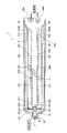
- FIG. 1 is a partial cross-sectional view of a hydrogen storage device including a heat exchanger according to the first embodiment of the present invention.
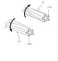
- FIG. 2 is a perspective view of the first spiral tube and the second spiral tube included in the heat exchanger according to the first embodiment of the present invention.
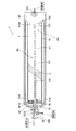
- FIG. 3 is a partial cross-sectional view of a hydrogen storage device including a heat exchanger according to the second embodiment of the present invention.
- FIG. 4 is a partial cross-sectional view of a hydrogen storage device including a heat exchanger according to the third embodiment of the present invention.
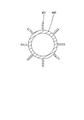
- Drawing 5 is a sectional view showing other shapes of the 1st spiral tube and the 2nd spiral tube which a heat exchanger concerning each embodiment of the present invention has.
- a hydrogen storage device 1 shown in FIG. 1 is mounted on a vehicle using hydrogen gas as a fuel, for example, and has a hydrogen storage chamber 2 for storing high-pressure hydrogen gas.
- the hydrogen storage device 1 includes a hollow liner 10, an end flange 20 attached to one end portion of the liner 10, and a base flange 30 attached to the other end portion of the liner 10 as pressure vessels that define the hydrogen storage chamber 2. And comprising.
- a reinforcing tube 40 surrounding the liner 10 is provided on the outer periphery of the liner 10.
- the material of the reinforcing tube 40 is a metal having a higher tensile strength than the liner 10 and a low coefficient of thermal expansion, such as high-tensile steel.
- a hollow sub-tank 50 is provided as a tank for storing the hydrogen storage material 3.
- the opening on one end side of the sub tank 50 is closed by the base flange 30, and the opening on the other end side is closed by the lid member 60.
- the lid member 60 is provided with a through hole 61 that allows the hydrogen storage chamber 2 in the liner 10 and the inside of the sub tank 50 to communicate with each other, and a mesh 62 that covers the through hole 61.
- the lid member 60 is connected to the end flange 20.
- the hydrogen storage material 3 is confined inside the sub tank 50 by the mesh 62. For convenience, a part of the hydrogen storage material 3 stored in the sub tank 50 is shown in FIG. 1, but the hydrogen storage material 3 is stored throughout the sub tank 50.
- the hydrogen storage material 3 for example, a powdered hydrogen storage alloy is used.
- the hydrogen storage alloy is an alloy of hydrogen storage properties.
- the hydrogen storage material 3 stores several hundred times or more hydrogen gas compared to the atmosphere.
- the hydrogen storage material 3 is not limited to a hydrogen storage alloy, and other materials having a property of taking in hydrogen may be used.
- the end flange 20 is provided with a hydrogen gas supply / discharge passage 21 for supplying and discharging hydrogen gas to and from the hydrogen storage chamber 2.
- the hydrogen gas supply / discharge passage 21 communicates with a hydrogen gas supply source and a hydrogen gas supply destination through a pipe connected to the end flange 20.
- the base flange 30 is provided with a first port 30A for supplying a heat medium to the heat exchanger 100 described later, and a second port 30B for discharging the heat medium that has passed through the heat exchanger 100.
- a heat exchanger 100 for cooling or heating the hydrogen storage material 3 is provided in the sub tank 50.
- the heat exchanger 100 exchanges heat with the hydrogen storage material 3 when the heat medium supplied and discharged from the outside of the hydrogen storage device 1 through the first and second ports 30A and 30B passes through the inside.
- the heat medium for example, water or oil is used as the heat medium, but the heat medium is not limited thereto, and other liquid or gas may be used.
- a high temperature heating medium (heat medium) is supplied to the heat exchanger 100 from the external supply source through the first port 30A.
- the hydrogen storage material 3 is heated by the heating medium supplied to the heat exchanger 100, the hydrogen gas released from the hydrogen storage material 3 is taken out through the hydrogen gas supply / discharge passage 21 of the end flange 20.
- the heat exchanger 100 includes a heat exchange pipe 101 through which a heat medium supplied and discharged from the outside of the hydrogen storage device 1 passes, and a tube flange 102 that supports the base end of the heat exchange pipe 101 and is fixed to the base flange 30. And comprising.
- the heat exchange pipe 101 has a supply path 110 ⁇ / b> A to which a heat medium is supplied at one end, and a return path that is provided in parallel with the forward path part 110 and has a discharge port 120 ⁇ / b> A that discharges the heat medium that has passed through the interior.
- Part 120 and a connecting part 130 that connects the other ends of the forward path part 110 and the return path part 120.
- the connection part 130 is provided with a connection path 131 that guides the heat medium passing through the forward path part 110 to the return path part 120.
- the forward path portion 110 includes a first spiral tube 111 formed in a spiral shape having an irregular cross-sectional shape and twisted along the longitudinal direction, and an outward path support portion that is a straight tube having one end supported by the tube flange 102 and a circular section. 112, and a forward connection part 113 that is a straight pipe that is connected to the connection part 130 and has a circular cross section.
- the first spiral tube 111 of the forward path portion 110 is formed in a spiral shape in which a plurality of convex portions 111A protruding radially are twisted along the longitudinal direction.
- the surface area is increased by making the cross-sectional shape an irregular shape, the heat transfer property is improved.
- the forward path support part 112 of the forward path part 110 has a supply port 110 ⁇ / b> A at one end supported by the tube flange 102 and the other end connected to the first spiral tube 111.
- the forward path support part 112 guides the heat medium supplied through the supply port 110 ⁇ / b> A to the inside of the first spiral tube 111.
- the forward connection part 113 of the forward part 110 has one end connected to the first spiral tube 111 and the other end connected to the connection part 130.
- the forward connection part 113 guides the heat medium that has passed through the inside of the first spiral tube 111 to the connection part 130.
- the return path section 120 includes a second spiral tube 121 formed in a spiral shape having an irregular cross-sectional shape and twisted along the longitudinal direction, and one end supported by the tube flange 102 and a circular cross section.
- the return path connection portion 123 of the return path portion 120 has one end connected to the second spiral tube 121 and the other end connected to the connection portion 130.
- the return path connection part 123 guides the heat medium guided through the connection part 130 to the inside of the second spiral tube 121.
- the second spiral tube 121 of the return path portion 120 is formed in a spiral shape in which a plurality of convex portions 121 ⁇ / b> A projecting radially are twisted along the longitudinal direction.
- the second spiral tube 121 is formed by twisting in a direction opposite to the twist direction of the first spiral tube 111 of the forward path portion 110 as indicated by an arrow in FIG.
- the return path support part 122 of the return path part 120 has an outlet 120 ⁇ / b> A at one end supported by the tube flange 102 and the other end connected to the second spiral tube 121.
- the return path support part 122 discharges the heat medium that has passed through the second spiral tube 121 through the discharge port 120A to the outside.
- the first spiral tube 111 of the forward path part 110 and the second spiral pipe 121 of the return path part 120, the forward path support part 112 and the return path support part 122, and the forward path connection part 113 and the return path connection part 123 are mutually connected. The same length is formed.
- the forward path portion 110 may be formed by processing a single tube to form the first spiral tube 111, the forward path support portion 112, and the forward path connection portion 113, or by connecting them by welding or the like. Also good.
- the return path portion 120 may be formed by processing one pipe, or may be formed by connecting each of them by welding or the like.
- the heat exchange pipe 101 is formed in a U shape whose base end is cantilevered by the tube flange 102. Inside the heat exchange pipe 101, the heat medium supplied from the outside through the supply port 110 ⁇ / b> A circulates through the forward path part 110, the connection part 130, and the return path part 120. Exchanges can be made.
- first spiral tube 111 and the second spiral tube 121 are formed in opposite directions with different twist directions. For this reason, the torsional moments generated in each of the first helical tube 111 and the second helical tube 121 by the external pressure cancel each other. Therefore, the heat exchanger 100 as a whole is prevented from generating a torsional moment due to external pressure.
- the heat exchange pipe 101 of the heat exchanger 100 includes a first spiral tube 111 and a second spiral tube 121 formed in a spiral shape in which a plurality of projecting portions 111A and 121A projecting radially are twisted along the longitudinal direction. Yes. Since the first spiral tube 111 and the second spiral tube 121 are opposite to each other in the twist directions of the convex portions 111A and 121A, the torsion moments generated by the external pressure cancel each other. For this reason, durability of the heat exchanger 100 can be improved.
- the heat exchanger 100 can improve the durability, the heat exchanger 100 can be prevented from being deformed by the external pressure, and the lifetime can be prevented from being shortened.
- the forward path portion 110 of the heat exchange pipe 101 has the first spiral tube 111
- the return path portion 120 has the second spiral tube 121.
- the forward path portion 210 and the return path portion 220 have the first spiral tube 211 and the second spiral in which the twist directions are opposite to each other.
- tube 221 differs from the heat exchanger 100 which concerns on 1st Embodiment.
- the forward path 210 of the heat exchange pipe 201 has a supply port 210A to which a heat medium is supplied at one end.
- the return path 220 of the heat exchange pipe 201 has a discharge port 220A for discharging the heat medium that has passed through the inside at one end.
- the first spiral pipe 211 and the second spiral pipe 221 are connected by an intermediate part 240.
- the intermediate portion 240 is a straight portion having a circular cross section.
- the forward path part 210 and the return path part 220 have a pair of first spiral tube 211 and second spiral tube 221 respectively.
- the heat exchanger 200 may include two or more first spiral tubes 211 and second spiral tubes 221.
- the heat exchange pipe 101 includes the forward path part 110 having the first spiral pipe 111, the return path part 120 having the second spiral pipe 121, and the other end of the forward path part 110. And a connecting portion 130 that connects the other end of the return path portion 120 and is formed in a U shape.
- the heat exchange pipe 301 is a single straight pipe including the first spiral tube 310 and the second spiral tube 311. It differs from the heat exchanger 100 according to the first embodiment in that it is formed.
- the heat exchange pipe 301 of the heat exchanger 300 includes a first spiral tube 310 and a second spiral tube 311 whose twist directions are opposite to each other, and one end supported by the tube flange 102 and the other end to the second spiral tube 311.
- a first support part 313 which is a straight pipe to be connected
- a second support part 314 whose one end is connected to the first spiral pipe 310 and the other end is supported by the end flange 20, and the first spiral pipe 310 and the second spiral.
- An intermediate portion 315 that is a straight tube connecting the tube 311.
- the first spiral tube 310 and the second spiral tube 311 are spiral tubes having shapes that differ from the first spiral tube 111 and the second spiral tube 121 in the first embodiment only in length, respectively.
- the heat exchange pipe 301 is formed such that the first spiral tube 310 and the second spiral tube 311 have the same length.
- FIG. 4 shows a case where the heat exchange pipe 301 includes a pair of the first spiral tube 310 and the second spiral tube 311, but includes two or more first spiral tubes 310 and two second spiral tubes 311. May be.
- the first support part 313 of the heat exchange pipe 301 has a supply port 313A through which a heat medium is supplied from the outside.
- the heat medium is introduced into the heat exchange pipe 301 through the supply port 313A.
- the second support portion 314 of the heat exchange pipe 301 has a discharge port 314A for discharging the heat medium that has passed through the heat exchange pipe 301 to the outside.
- the end flange 20 includes a hydrogen gas supply / discharge passage 21 that supplies and discharges hydrogen gas to and from the hydrogen storage chamber 2, and a discharge passage 22 that communicates with the discharge port 314A and discharges the heat medium guided from the heat exchange pipe 301 to the outside. Are provided.
- the heat medium supplied from the outside is discharged to the outside through the supply port 313A, the heat exchange pipe 301, the discharge port 314A, and the discharge passage 22.
- the heat exchangers 100, 200, and 300 have been described as being provided in the hydrogen storage device 1, but may be provided in other pressure vessels.
- first spiral tubes 111, 211, 310 and the second spiral tubes 121, 221, 311 of the heat exchange pipes 101, 201, 301 have a plurality of convex portions 111A, 121A whose radial sections protrude radially. It is formed in a spiral shape twisted along.
- first spiral tubes 111, 211, 310 and the second spiral tubes 121, 221, 311 have other non-circular irregular shapes, for example, polygonal cross sections along the longitudinal direction. You may form in the shape of a twisted spiral.
- the first spiral tubes 111, 211, 310 and the second spiral tubes 121, 221, 311 include a hollow tube 400 that allows passage of a heat medium, and a hollow tube 400.
- You may form in the irregular cross-sectional shape which has the fin 401 formed in the outer periphery.
- the hollow tube 400 may be formed in a circular cross-sectional shape or an irregular cross-sectional shape.
- the fin 401 may be formed to extend linearly in the radial direction of the hollow tube 400, or may be formed in another shape, for example, a bent shape.
- the heat exchange pipes 101, 201, 301 are formed so that the total lengths of the first spiral tubes 111, 211, 310 and the second spiral tubes 121, 221, 311 are the same.
- the total lengths of the first spiral tubes 111, 221 and 310 and the second spiral tubes 121, 221 and 311 are the same. May be formed differently. In this case, the torsional moments generated by the external pressure cannot be completely canceled out from each other, but the magnitude of the torsional moments can be reduced.
Landscapes
- Engineering & Computer Science (AREA)
- Physics & Mathematics (AREA)
- Mechanical Engineering (AREA)
- General Engineering & Computer Science (AREA)
- Thermal Sciences (AREA)
- Geometry (AREA)
- Heat-Exchange Devices With Radiators And Conduit Assemblies (AREA)
- Filling Or Discharging Of Gas Storage Vessels (AREA)
Abstract
圧力容器内に設けられる熱交換器であって、圧力容器外から給排される熱媒体が内部を通過する熱交換パイプを備え、熱交換パイプは、異形断面形状を有し長手方向に沿ってねじれた螺旋状に形成される第1螺旋管及び第2螺旋管を備え、第1螺旋管及び第2螺旋管は、ねじれの向きが互いに逆向きである。
Description
本発明は、圧力容器内に設けられる熱交換器及びこれを備えた水素貯蔵装置に関するものである。
従来、圧力容器内に設けられる熱交換器として、圧力容器外から給排される熱媒体が内部を通過する熱交換パイプを備えるものが知られている。JP2013-15174Aには、その断面が放射状に突出する複数の管凸部と隣り合う管凸部の間で窪む複数の管凹部とを有し、管凸部と管凹部が軸方向に螺旋状に延びて形成される熱交換パイプを備えた熱交換器が開示されている。
圧力容器内に設けられる熱交換器の熱交換パイプには、外圧が作用する。螺旋状にねじれる熱交換パイプに外圧が作用すると、ねじれが増大する方向にねじりモーメントが発生する。圧力容器内に設けられる熱交換器には、このようなねじりモーメントが常に作用するため、熱交換器の耐久性を向上させることが求められている。
本発明は、熱交換器の耐久性を向上させることを目的とする。
本発明のある態様によれば、圧力容器内に設けられる熱交換器であって、圧力容器外から給排される熱媒体が内部を通過する熱交換パイプを備え、熱交換パイプは、異形断面形状を有し長手方向に沿ってねじれた螺旋状に形成された第1螺旋管及び第2螺旋管を有し、第1螺旋管及び第2螺旋管は、ねじれの向きが互いに逆向きである。
(第1実施形態)
以下、図面を参照して、本発明の第1実施形態に係る熱交換器100について説明する。以下では、水素貯蔵装置1に設けられる熱交換器100について説明する。
以下、図面を参照して、本発明の第1実施形態に係る熱交換器100について説明する。以下では、水素貯蔵装置1に設けられる熱交換器100について説明する。
まず、図1を参照して、熱交換器100が設けられる水素貯蔵装置1について説明する。
図1に示す水素貯蔵装置1は、例えば水素ガスを燃料とする車両に搭載されるものであり、高圧の水素ガスを貯蔵する水素貯蔵室2を有する。
水素貯蔵装置1は、水素貯蔵室2を画成する圧力容器として、中空状のライナ10と、ライナ10の一端部に取り付けられるエンドフランジ20と、ライナ10の他端部に取り付けられるベースフランジ30と、を備える。
ライナ10の外周には、ライナ10を包囲する補強チューブ40が設けられる。補強チューブ40の材質は、ライナ10より引張強度が高く、熱膨張率が小さい金属であり、例えば高張力鋼である。
ライナ10の内部には、水素貯蔵物質3を収容するタンクとして、中空状のサブタンク50が設けられる。サブタンク50の一端側の開口はベースフランジ30によって塞がれ、他端側の開口は蓋部材60によって塞がれる。
蓋部材60には、ライナ10内の水素貯蔵室2とサブタンク50の内部とを連通する通孔61と、通孔61を覆うメッシュ62と、が設けられる。蓋部材60は、エンドフランジ20に連結される。
水素貯蔵物質3は、メッシュ62によってサブタンク50の内部に閉じ込められる。図1には便宜上、サブタンク50に収容される水素貯蔵物質3の一部を示しているが、水素貯蔵物質3はサブタンク50内の全域に収容される。
水素貯蔵物質3は、例えば粉末状の水素吸蔵合金が用いられる。水素吸蔵合金は、水素を吸蔵する性質があるものを合金化したものである。水素貯蔵物質3には、大気中に比べて数100倍以上の水素ガスが貯蔵される。水素貯蔵物質3は、水素吸蔵合金に限らず、水素を取り込む性質のある他の物質を用いてもよい。
エンドフランジ20には、水素貯蔵室2に水素ガスを給排する水素ガス給排通路21が設けられる。水素ガス給排通路21は、エンドフランジ20に接続される配管を介して水素ガスの供給源と水素ガスの供給先とに連通される。
ベースフランジ30には、後述する熱交換器100に熱媒体を供給する第1ポート30Aと、熱交換器100内を通過した熱媒体を排出する第2ポート30Bと、が設けられる。
サブタンク50の内部には、水素貯蔵物質3を冷却または加熱する熱交換器100が設けられる。熱交換器100は、水素貯蔵装置1の外部から第1,第2ポート30A,30Bを通じて給排される熱媒体が内部を通過することによって、水素貯蔵物質3との間で熱交換を行う。熱媒体は、例えば水またはオイルが用いられるが、これに限らず、他の液体または気体を用いてもよい。
水素貯蔵装置1への水素ガス充填時には、エンドフランジ20の水素ガス給排通路21を通じて外部の供給源から高圧の水素ガスがライナ10内の水素貯蔵室2に供給される。そして、第1ポート30Aを通じて外部の供給源から低温の冷却媒体(熱媒体)が熱交換器100に供給される。熱交換器100に供給される冷却媒体によって水素貯蔵物質3が冷却されることにより、水素ガスが水素貯蔵物質3に貯蔵される。
一方、水素貯蔵装置1から水素ガスが取り出されるときには、外部の供給源から第1ポート30Aを通じて高温の昇温媒体(熱媒体)が熱交換器100に供給される。熱交換器100に供給される昇温媒体によって水素貯蔵物質3が加熱されることにより、水素貯蔵物質3から放出される水素ガスがエンドフランジ20の水素ガス給排通路21を通じて取り出される。
次に、熱交換器100について具体的に説明する。
熱交換器100は、水素貯蔵装置1の外部から給排される熱媒体が内部を通過する熱交換パイプ101と、熱交換パイプ101の基端を支持しベースフランジ30に固定されるチューブフランジ102と、を備える。
熱交換パイプ101は、熱媒体が供給される供給口110Aを一端に有する往路部110と、往路部110と平行に設けられ、内部を通過した熱媒体を排出する排出口120Aを一端に有する復路部120と、往路部110と復路部120の他端同士を連結する連結部130と、を備える。連結部130には、往路部110内を通過する熱媒体を復路部120へ導く連結路131が設けられる。
往路部110は、異形断面形状を有し長手方向に沿ってねじれた螺旋状に形成される第1螺旋管111と、一端がチューブフランジ102に支持され断面が円形のストレート管である往路支持部112と、連結部130に連結され断面が円形のストレート管である往路接続部113と、を備える。
往路部110の第1螺旋管111は、図2に示すように、放射状に突出する複数の凸部111Aが長手方向に沿ってねじれた螺旋状に形成される。このように、断面形状を異形形状とすることにより、表面積が大きくなるため、熱伝達性が向上する。
往路部110の往路支持部112は、一端の供給口110Aがチューブフランジ102に支持され、他端が第1螺旋管111に連結される。往路支持部112は、供給口110Aを通じて供給される熱媒体を第1螺旋管111の内部へと導く。
往路部110の往路接続部113は、一端が第1螺旋管111に連結され、他端が連結部130に連結される。往路接続部113は、第1螺旋管111の内部を通過した熱媒体を連結部130へと導く。
図1に示すように、復路部120は、異形断面形状を有し長手方向に沿ってねじれた螺旋状に形成される第2螺旋管121と、一端がチューブフランジ102に支持され断面が円形のストレート管である復路支持部122と、連結部130に連結され断面が円形のストレート管である復路接続部123と、を備える。
復路部120の復路接続部123は、一端が第2螺旋管121に連結され、他端が連結部130に連結される。復路接続部123は、連結部130を通じて導かれた熱媒体を第2螺旋管121の内部へと導く。
復路部120の第2螺旋管121は、図2に示すように、放射状に突出する複数の凸部121Aが長手方向に沿ってねじれた螺旋状に形成される。第2螺旋管121は、図2中矢印で示すように往路部110の第1螺旋管111のねじれの向きとは異なる逆向きにねじれて形成される。
復路部120の復路支持部122は、一端の排出口120Aがチューブフランジ102に支持され、他端が第2螺旋管121に連結される。復路支持部122は、排出口120Aを通じて第2螺旋管121を通過した熱媒体を外部へと排出する。
図1に示すように、往路部110の第1螺旋管111と復路部120の第2螺旋管121、往路支持部112と復路支持部122、及び往路接続部113と復路接続部123は、互いに同一の長さに形成される。
また、往路部110は、1本の管を加工することにより第1螺旋管111、往路支持部112及び往路接続部113を形成してもよいし、それぞれを溶接等で接続して形成してもよい。復路部120も同様に、1本の管を加工して形成してもよいし、それぞれを溶接等で接続して形成してもよい。
このように、熱交換パイプ101は、基端がチューブフランジ102に片持ち支持されるU字状に形成される。熱交換パイプ101の内部には、供給口110Aを通じて外部から供給される熱媒体が、往路部110、連結部130、復路部120を通過して循環するため、水素貯蔵物質3との間で熱交換を行うことができる。
ライナ10内の水素貯蔵物質3は、高圧状態にあるため、熱交換パイプ101には外圧が作用する。熱交換パイプ101の第1螺旋管111及び第2螺旋管121の個々には、ねじれが増大するように外圧が作用するため、それぞれにねじりモーメントが発生する。
しかし、第1螺旋管111と第2螺旋管121は、ねじれの向きが互いに異なる逆向きに形成される。このため、外圧によって第1螺旋管111と第2螺旋管121のそれぞれに発生するねじりモーメントは互いに打ち消しあう。したがって、熱交換器100全体としては、外圧によるねじりモーメントの発生が防止される。
以上の第1実施形態によれば、以下に示す効果を奏する。
熱交換器100の熱交換パイプ101は、放射状に突出する複数の凸部111A,121Aが長手方向に沿ってねじれた螺旋状に形成される第1螺旋管111及び第2螺旋管121を備えている。第1螺旋管111及び第2螺旋管121は、凸部111A,121Aのねじれの向きが互いに異なる逆向きであるため、外圧によって発生するねじりモーメントが互いに打ち消しあう。このため、熱交換器100の耐久性を向上させることができる。
このように、熱交換器100は耐久性を向上させることができるため、外圧によって変形することが抑制され、寿命低下を防止することができる。
(第2実施形態)
次に、図3を参照して、本発明の第2実施形態に係る熱交換器200について説明する。以下では、上記第1実施形態と異なる点を中心に説明し、上記第1実施形態の熱交換器100と同一の構成には同一の符号を付して説明を省略する。
次に、図3を参照して、本発明の第2実施形態に係る熱交換器200について説明する。以下では、上記第1実施形態と異なる点を中心に説明し、上記第1実施形態の熱交換器100と同一の構成には同一の符号を付して説明を省略する。
上記第1実施形態では、熱交換パイプ101の往路部110は第1螺旋管111を有し、復路部120は第2螺旋管121を有する構成であった。これに対し、第2実施形態に係る熱交換器200では、図3に示すように、往路部210及び復路部220は、ねじれの向きが互いに逆向きである第1螺旋管211及び第2螺旋管221をそれぞれが有する点において、第1実施形態に係る熱交換器100と相違する。
熱交換パイプ201の往路部210は、熱媒体が供給される供給口210Aを一端に有する。熱交換パイプ201の復路部220は、内部を通過した熱媒体を排出する排出口220Aを一端に有する。往路部210及び復路部220において、第1螺旋管211と第2螺旋管221は、中間部240によって連結される。中間部240は、円形断面を有するストレート部である。
熱交換器200では、往路部210及び復路部220は、それぞれ一対の第1螺旋管211及び第2螺旋管221を有している。これに対し、熱交換器200は、第1螺旋管211及び第2螺旋管221をそれぞれ2以上有していてもよい。この場合には、熱交換パイプ201が有する第1螺旋管211の長さの総和と第2螺旋管221の長さの総和が同一となるように形成されることが好ましい。第1螺旋管211と第2螺旋管221の長さの総和が同一に形成されることによって、外圧によって生じるねじりモーメントを互いに完全に打ち消しあうことができる。
このような第2実施形態に係る熱交換器200によれば、ねじれの向きが互いに逆向きである第1螺旋管211と第2螺旋管221を備えているため、上記第1実施形態と同様の効果を奏する。
(第3実施形態)
次に、図4を参照して、本発明の第3実施形態に係る熱交換器300について説明する。以下では、上記第1実施形態と異なる点を中心に説明し、上記第1実施形態の熱交換器100と同一の構成には同一の符号を付して説明を省略する。
次に、図4を参照して、本発明の第3実施形態に係る熱交換器300について説明する。以下では、上記第1実施形態と異なる点を中心に説明し、上記第1実施形態の熱交換器100と同一の構成には同一の符号を付して説明を省略する。
上記第1実施形態に係る熱交換器100では、熱交換パイプ101は、第1螺旋管111を有する往路部110と、第2螺旋管121を有する復路部120と、往路部110の他端と復路部120の他端とを連結する連結部130と、を備え、U字状に形成される構成である。これに対し、第3実施形態に係る熱交換器300では、図4に示すように、熱交換パイプ301は、第1螺旋管310及び第2螺旋管311を備える一本の直線状のパイプとして形成される点において、第1実施形態に係る熱交換器100と相違する。
熱交換器300の熱交換パイプ301は、ねじれの向きが互いに逆向きである第1螺旋管310及び第2螺旋管311と、一端がチューブフランジ102に支持され他端が第2螺旋管311に連結されるストレート管である第1支持部313と、一端が第1螺旋管310に連結され他端がエンドフランジ20に支持される第2支持部314と、第1螺旋管310と第2螺旋管311を連結するストレート管である中間部315と、を備える。
第1螺旋管310及び第2螺旋管311は、それぞれ第1実施形態における第1螺旋管111及び第2螺旋管121と長さのみが異なる形状の螺旋管である。熱交換パイプ301は、第1螺旋管310と第2螺旋管311の長さが、同一となるように形成される。また、図4では、熱交換パイプ301は、一対の第1螺旋管310及び第2螺旋管311を有する場合を示すが、第1螺旋管310及び第2螺旋管311をそれぞれ2以上有していてもよい。
熱交換パイプ301の第1支持部313は、外部から熱媒体が供給される供給口313Aを有している。供給口313Aを通じて、熱交換パイプ301内に熱媒体が導かれる。
熱交換パイプ301の第2支持部314は、熱交換パイプ301内を通過した熱媒体を外部へ排出する排出口314Aを有している。
エンドフランジ20には、水素貯蔵室2に水素ガスを給排する水素ガス給排通路21と、排出口314Aと連通し熱交換パイプ301から導かれた熱媒体を外部へ排出する排出通路22と、が設けられる。
外部から供給される熱媒体は、供給口313A、熱交換パイプ301、排出口314A、及び排出通路22を通じて、外部へと排出される。
以上の第3実施形態によれば、上記第1実施形態と同様の効果を奏する。
以上、本発明の実施形態について説明したが、上記実施形態は本発明の適用例の一部を示したに過ぎず、本発明の技術的範囲を上記実施形態の具体的構成に限定する趣旨ではない。
上記実施形態では、熱交換器100,200,300は、水素貯蔵装置1に設けられる場合について説明したが、その他の圧力容器内に設けてもよい。
また、熱交換パイプ101,201,301が有する第1螺旋管111,211,310及び第2螺旋管121,221,311は、その断面が放射状に突出する複数の凸部111A,121Aが長手方向に沿ってねじれた螺旋状に形成されるものである。これに代えて、第1螺旋管111,211,310及び第2螺旋管121,221,311の断面形状を、その他の円形ではない異形形状、例えば多角形断面を有して長手方向に沿ってねじれた螺旋状に形成してもよい。
また、図5に断面図を示すように、第1螺旋管111,211,310及び第2螺旋管121,221,311は、熱媒体の通過を許容する中空管400と、中空管400の外周に形成されるフィン401と、を有する異形断面形状に形成してもよい。中空管400は、円形断面形状に形成されてもよく、異形断面形状に形成されてもよい。フィン401は、図5に示すように、中空管400の径方向に直線状に延びて形成されてもよいし、その他の形状、例えば屈曲した形状に形成されてもよい。
また、熱交換パイプ101,201,301は、第1螺旋管111,211,310と第2螺旋管121,221,311の長さの総和が同一となるように形成される。外圧によって生じるねじりモーメントを完全に打ち消すためには、第1螺旋管111,221,310と第2螺旋管121,221,311の長さの総和が同一となることが好ましいが、長さの総和が異なるように形成してもよい。この場合、外圧によって生じるねじりモーメントを互いに完全に打ち消しあうことはできないが、そのねじりモーメントの大きさを減少することができる。
本願は2013年12月24日に日本国特許庁に出願された特願2013-264992に基づく優先権を主張し、この出願の全ての内容は参照により本明細書に組み込まれる。
Claims (6)
- 圧力容器内に設けられる熱交換器であって、
前記圧力容器外から給排される熱媒体が内部を通過する熱交換パイプを備え、
前記熱交換パイプは、異形断面形状を有し長手方向に沿ってねじれた螺旋状に形成された第1螺旋管及び第2螺旋管を有し、
前記第1螺旋管及び前記第2螺旋管は、ねじれの向きが互いに逆向きである熱交換器。 - 請求項1に記載の熱交換器であって、
前記第1螺旋管及び前記第2螺旋管は、放射状に突出する複数の凸部が長手方向に沿ってねじれた螺旋状に形成される熱交換器。 - 請求項1に記載の熱交換器であって、
前記熱交換パイプは、
前記第1螺旋管を有し、熱媒体が供給される供給口を一端に有する往路部と、
前記第2螺旋管を有し、前記往路部と平行に設けられ、内部を通過した熱媒体を排出する排出口を一端に有する復路部と、
前記往路部と前記復路部との他端同士を連結し、前記往路部内を通過する熱媒体を前記復路部へ導く連結部と、を備える熱交換器。 - 請求項1に記載の熱交換器であって、
前記熱交換パイプは、前記第1螺旋管及び第2螺旋管を備える1本の直線状のパイプとして形成される熱交換器。 - 請求項1に記載の熱交換器であって、
前記熱交換パイプは、前記第1螺旋管の長さの総和と前記第2螺旋管の長さの総和が同一となるように形成される熱交換器。 - 水素貯蔵装置であって、
水素ガスを貯蔵する水素貯蔵物質を収容する前記圧力容器内に設けられる請求項1に記載の熱交換器を備え、
前記水素貯蔵物質と前記熱交換器に給排される熱媒体との間における熱交換によって水素ガスを貯蔵する水素貯蔵装置。
Applications Claiming Priority (2)
| Application Number | Priority Date | Filing Date | Title |
|---|---|---|---|
| JP2013264992A JP2015121346A (ja) | 2013-12-24 | 2013-12-24 | 熱交換器及び水素貯蔵装置 |
| JP2013-264992 | 2013-12-24 |
Publications (1)
| Publication Number | Publication Date |
|---|---|
| WO2015098438A1 true WO2015098438A1 (ja) | 2015-07-02 |
Family
ID=53478306
Family Applications (1)
| Application Number | Title | Priority Date | Filing Date |
|---|---|---|---|
| PCT/JP2014/081887 Ceased WO2015098438A1 (ja) | 2013-12-24 | 2014-12-02 | 熱交換器及び水素貯蔵装置 |
Country Status (2)
| Country | Link |
|---|---|
| JP (1) | JP2015121346A (ja) |
| WO (1) | WO2015098438A1 (ja) |
Cited By (1)
| Publication number | Priority date | Publication date | Assignee | Title |
|---|---|---|---|---|
| GB2634339A (en) * | 2023-10-05 | 2025-04-09 | Univ Bristol | Hydrogen storage bed |
Families Citing this family (1)
| Publication number | Priority date | Publication date | Assignee | Title |
|---|---|---|---|---|
| JP7153608B2 (ja) * | 2019-05-24 | 2022-10-14 | 岩谷産業株式会社 | 水素トーチ |
Citations (5)
| Publication number | Priority date | Publication date | Assignee | Title |
|---|---|---|---|---|
| JPS446299Y1 (ja) * | 1966-07-15 | 1969-03-07 | ||
| US20030209147A1 (en) * | 2002-05-09 | 2003-11-13 | Vitaliy Myasnikov | Honeycomb hydrogen storage structure |
| JP2004332854A (ja) * | 2003-05-08 | 2004-11-25 | Toyota Industries Corp | 圧力容器 |
| JP2011226763A (ja) * | 2010-03-31 | 2011-11-10 | Noritz Corp | 熱交換器 |
| JP2013015174A (ja) * | 2011-07-01 | 2013-01-24 | Kyb Co Ltd | 水素貯蔵容器 |
-
2013
- 2013-12-24 JP JP2013264992A patent/JP2015121346A/ja active Pending
-
2014
- 2014-12-02 WO PCT/JP2014/081887 patent/WO2015098438A1/ja not_active Ceased
Patent Citations (5)
| Publication number | Priority date | Publication date | Assignee | Title |
|---|---|---|---|---|
| JPS446299Y1 (ja) * | 1966-07-15 | 1969-03-07 | ||
| US20030209147A1 (en) * | 2002-05-09 | 2003-11-13 | Vitaliy Myasnikov | Honeycomb hydrogen storage structure |
| JP2004332854A (ja) * | 2003-05-08 | 2004-11-25 | Toyota Industries Corp | 圧力容器 |
| JP2011226763A (ja) * | 2010-03-31 | 2011-11-10 | Noritz Corp | 熱交換器 |
| JP2013015174A (ja) * | 2011-07-01 | 2013-01-24 | Kyb Co Ltd | 水素貯蔵容器 |
Cited By (2)
| Publication number | Priority date | Publication date | Assignee | Title |
|---|---|---|---|---|
| GB2634339A (en) * | 2023-10-05 | 2025-04-09 | Univ Bristol | Hydrogen storage bed |
| WO2025073717A1 (en) * | 2023-10-05 | 2025-04-10 | The University Of Bristol | Hydrogen storage bed |
Also Published As
| Publication number | Publication date |
|---|---|
| JP2015121346A (ja) | 2015-07-02 |
Similar Documents
| Publication | Publication Date | Title |
|---|---|---|
| CN103620293B (zh) | 储氢容器 | |
| CN107257898B (zh) | 压力容器流体歧管组件 | |
| BRPI0510010B1 (pt) | Vaso de pressão com camisa de proteção | |
| US7455723B2 (en) | Hydrogen storage and release device | |
| JP6285867B2 (ja) | 金属水素化物の形態で水素を貯蔵するタンク | |
| JP2008281105A (ja) | 水素ガス貯蔵装置 | |
| JP2007511735A (ja) | らせん状多重チューブ熱交換器 | |
| ES2669985T3 (es) | Método mejorado para producir recipientes de material compuesto de alta resistencia con revestimiento de metal interior y recipientes producidos mediante dicho método | |
| JP2003156294A5 (ja) | ||
| WO2015098438A1 (ja) | 熱交換器及び水素貯蔵装置 | |
| ES2961914T3 (es) | Intercambiador de calor de doble tubo y método de fabricación del mismo | |
| US7287578B2 (en) | Connection between a cooled double-wall pipe and an uncooled pipe and double-pipe heat exchanger including said connection | |
| KR101995982B1 (ko) | 액화천연가스 연료 선박용 기화기 | |
| ITVI20130201A1 (it) | Radiatore in alluminio a tubi ellittici alettati. | |
| JP2011058786A (ja) | 熱交換器 | |
| US4771738A (en) | Dual sleeve boiler mounting apparatus | |
| JP4075732B2 (ja) | ヒートポンプ式給湯機用の熱交換器 | |
| KR102294972B1 (ko) | 열교환기 | |
| JP6307289B2 (ja) | 熱交換器及び水素貯蔵装置 | |
| JP4370115B2 (ja) | 水素貯蔵タンク及びその製造方法 | |
| JP5541779B2 (ja) | オープンラック式気化器 | |
| CN113898867A (zh) | 一种用于机动车辆的压缩气罐的制造方法 | |
| JP2005003347A (ja) | フィン付き蛇行管およびこれを用いた空温式液化ガス気化器 | |
| WO2018197701A1 (en) | Austenitic stainless steel tube material in an lng vaporiser | |
| JP7604238B2 (ja) | 高圧タンクを製造する方法 |
Legal Events
| Date | Code | Title | Description |
|---|---|---|---|
| 121 | Ep: the epo has been informed by wipo that ep was designated in this application |
Ref document number: 14875802 Country of ref document: EP Kind code of ref document: A1 |
|
| NENP | Non-entry into the national phase |
Ref country code: DE |
|
| 122 | Ep: pct application non-entry in european phase |
Ref document number: 14875802 Country of ref document: EP Kind code of ref document: A1 |