WO2015098243A1 - 画像処理装置、撮像装置、プログラム及び画像処理方法 - Google Patents
画像処理装置、撮像装置、プログラム及び画像処理方法 Download PDFInfo
- Publication number
- WO2015098243A1 WO2015098243A1 PCT/JP2014/077286 JP2014077286W WO2015098243A1 WO 2015098243 A1 WO2015098243 A1 WO 2015098243A1 JP 2014077286 W JP2014077286 W JP 2014077286W WO 2015098243 A1 WO2015098243 A1 WO 2015098243A1
- Authority
- WO
- WIPO (PCT)
- Prior art keywords
- image
- band
- reference image
- interpolation
- processing
- Prior art date
- Legal status (The legal status is an assumption and is not a legal conclusion. Google has not performed a legal analysis and makes no representation as to the accuracy of the status listed.)
- Ceased
Links
Images







Classifications
-
- H—ELECTRICITY
- H04—ELECTRIC COMMUNICATION TECHNIQUE
- H04N—PICTORIAL COMMUNICATION, e.g. TELEVISION
- H04N9/00—Details of colour television systems
- H04N9/64—Circuits for processing colour signals
- H04N9/646—Circuits for processing colour signals for image enhancement, e.g. vertical detail restoration, cross-colour elimination, contour correction, chrominance trapping filters
-
- G—PHYSICS
- G06—COMPUTING OR CALCULATING; COUNTING
- G06T—IMAGE DATA PROCESSING OR GENERATION, IN GENERAL
- G06T3/00—Geometric image transformations in the plane of the image
- G06T3/40—Scaling of whole images or parts thereof, e.g. expanding or contracting
- G06T3/4015—Image demosaicing, e.g. colour filter arrays [CFA] or Bayer patterns
-
- G—PHYSICS
- G06—COMPUTING OR CALCULATING; COUNTING
- G06T—IMAGE DATA PROCESSING OR GENERATION, IN GENERAL
- G06T5/00—Image enhancement or restoration
- G06T5/50—Image enhancement or restoration using two or more images, e.g. averaging or subtraction
-
- G—PHYSICS
- G06—COMPUTING OR CALCULATING; COUNTING
- G06T—IMAGE DATA PROCESSING OR GENERATION, IN GENERAL
- G06T5/00—Image enhancement or restoration
- G06T5/70—Denoising; Smoothing
-
- H—ELECTRICITY
- H04—ELECTRIC COMMUNICATION TECHNIQUE
- H04N—PICTORIAL COMMUNICATION, e.g. TELEVISION
- H04N23/00—Cameras or camera modules comprising electronic image sensors; Control thereof
- H04N23/80—Camera processing pipelines; Components thereof
- H04N23/84—Camera processing pipelines; Components thereof for processing colour signals
- H04N23/843—Demosaicing, e.g. interpolating colour pixel values
-
- H—ELECTRICITY
- H04—ELECTRIC COMMUNICATION TECHNIQUE
- H04N—PICTORIAL COMMUNICATION, e.g. TELEVISION
- H04N25/00—Circuitry of solid-state image sensors [SSIS]; Control thereof
- H04N25/10—Circuitry of solid-state image sensors [SSIS]; Control thereof for transforming different wavelengths into image signals
- H04N25/11—Arrangement of colour filter arrays [CFA]; Filter mosaics
- H04N25/13—Arrangement of colour filter arrays [CFA]; Filter mosaics characterised by the spectral characteristics of the filter elements
- H04N25/134—Arrangement of colour filter arrays [CFA]; Filter mosaics characterised by the spectral characteristics of the filter elements based on three different wavelength filter elements
-
- G—PHYSICS
- G06—COMPUTING OR CALCULATING; COUNTING
- G06T—IMAGE DATA PROCESSING OR GENERATION, IN GENERAL
- G06T2207/00—Indexing scheme for image analysis or image enhancement
- G06T2207/10—Image acquisition modality
- G06T2207/10024—Color image
Definitions
- the present invention relates to an image processing device, an imaging device, a program, an image processing method, and the like.
- an imaging device In order to capture a full-color image, an imaging device is known in which a 3-band color filter of R (Red) G (Green) B (Blue) is provided on the front surface of the imaging device.
- multiband imaging has attracted attention for the purpose of faithful color reproduction of subjects.
- a multiband image pickup device a single plate multiband in which color filters of 4 bands or more (including values thereof) as shown in FIGS. 3A and 3B described later are provided on the front surface of the image pickup device.
- Some use an image sensor.
- a multi-band image sensor By using such a multi-band image sensor, a multi-band image can be acquired simply by capturing one image, and there are advantages such as downsizing of the apparatus and maintenance of a frame rate.
- an image pickup apparatus having such a multiband image pickup element it is necessary to perform an interpolation process in order to generate a multiband image from the picked up single plate image.
- interpolation is performed with reference to information on a band from which high frequency components can be accurately acquired A technique for generating an image is effective.
- Patent Document 1 discloses a technique for performing noise reduction processing for each band of a multiband image.
- Patent Document 2 discloses a technique for performing noise reduction processing after converting a 4-band multiband image into a 3-band RGB image in order to divert the conventional noise reduction processing for RGB images.
- an image processing apparatus an imaging apparatus, a program, an image processing method, and the like that can be provided can be provided.
- One embodiment of the present invention is an image acquisition unit that acquires a captured image captured using an imaging element having a multiband color filter array in which color filters of four or more bands (including values thereof) are arranged in an array.
- a low noise reference image generation unit that generates a low noise reference image on which noise reduction processing has been performed as a reference image to be used in the pixel value interpolation processing of the captured image, and the generated low noise reference image
- the present invention relates to an image processing apparatus including an interpolation image generation unit that performs the interpolation processing for each band of the multiband and generates an interpolation image in which pixel values of missing pixels are interpolated.
- noise reduction processing is performed on the pixel value of the reference band, and based on the low noise reference image with reduced noise, Interpolation of pixel values of bands other than the reference band is performed.
- the low-noise reference image generation unit performs pixel values obtained using a color filter corresponding to a reference band of the reference image among pixel values of the captured image.
- the low noise reference image may be generated by performing the noise reduction process.
- the interpolation image generation unit may calculate a new pixel value based on the low noise reference image even for a pixel having a pixel value in the captured image, and perform the interpolation.
- An image may be generated.
- the low-noise reference image generation unit selects a first band of the multibands as a reference band of the reference image, and the first band in the captured image
- the pixel value obtained using the color filter corresponding to is subjected to the noise reduction processing to generate the low noise reference image, and the interpolated image generation unit includes the low noise in the captured image.
- a pixel value obtained using the color filter corresponding to the third band of the multibands based on the interpolated image of the second band It performs the interpolation process may generate the interpolated image of the third band.
- the low noise reference image generation unit may perform the first operation on each pixel obtained using the color filter corresponding to the reference band of the reference image in the captured image.
- the pixel coordinate is transformed from the coordinate system to the second coordinate system, the noise reduction process is performed on the pixel value of each pixel of the reference band after the coordinate transformation, and each pixel after the noise reduction process
- the low-noise reference image may be generated by coordinate-transforming the pixel coordinates from the second coordinate system to the first coordinate system.
- the low-noise reference image generation unit rotates the pixel coordinates around the origin by a given angle as coordinate conversion from the first coordinate system to the second coordinate system. You may perform the coordinate transformation to make.
- the low noise reference image generation unit may select a band having the highest sample density among the multibands as a reference band of the reference image.
- the low-noise reference image generation unit selects, as the reference band of the reference image, a band having the strongest correlation with the color characteristic of the subject shown in the captured image among the multibands. May be.
- the low-noise reference image generation unit may include a correlation between each of the multibands and a color characteristic of a subject reflected in the captured image in the captured image, and in each of the bands.
- a reference band of the reference image may be selected from the multiband by performing at least one evaluation process of the noise amount.
- the low-noise reference image generation unit performs at least one of a high-frequency component and a luminance evaluation process on the captured image, so that the reference band of the reference image is selected from the multiband. May be selected.
- the low noise reference image generation unit may perform the interpolation process on pixel values obtained using a color filter corresponding to a reference band of the reference image among pixel values of the captured image.
- the low noise reference image may be generated by performing the noise reduction process on the pixel value of the reference band after the interpolation process.
- the low noise reference image generation unit includes a band conversion unit that converts a pixel value of at least one of the multibands into a pixel value of another band having a different wavelength band. Selects a band to be used as a reference band of the reference image from the band-converted bands, performs the noise reduction processing on the pixel values of the reference band obtained by band conversion, and A low noise reference image may be generated.
- the band conversion unit performs the band conversion based on the captured image to generate an RGB image
- the low noise reference image generation unit performs the noise reduction process. You may perform the noise reduction process for RGB images.
- the image sensor includes a signal conversion unit that converts each pixel value of the captured image into a luminance signal and a color difference signal, and the low noise reference image generation unit is configured to output the luminance signal and the color difference signal.
- the low noise reference image may be generated by performing different noise reduction processes.
- the present invention relates to an imaging apparatus including the image processing apparatus.
- the present invention relates to a program that causes a computer to function as each unit described above.
- a captured image captured using an imaging element having a multiband color filter array in which color filters of four or more bands (including values thereof) are arranged in an array is acquired.
- Generating a low noise reference image on which noise reduction processing has been performed as a reference image used in pixel value interpolation processing of the captured image, and for each of the multiband bands based on the generated low noise reference image The present invention relates to an image processing method for generating an interpolated image in which pixel values of missing pixels are interpolated by performing the interpolation process.
- FIG. 1 is a system configuration example of the first embodiment.
- FIG. 2 is a system configuration example of the imaging apparatus according to the first embodiment.
- 3A and 3B show examples of color filter arrays.
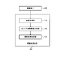
- FIG. 4 is a flowchart for explaining the flow of processing of the first embodiment.
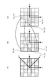
- 5A to 5C are explanatory diagrams of the coordinate conversion process and the noise reduction process.
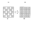
- 6A and 6B are explanatory diagrams of interpolation processing of a reference band.
- FIG. 7 is an explanatory diagram of interpolation processing for all bands.
- FIG. 8 is an explanatory diagram of a guided filter.
- FIG. 9 is an explanatory diagram of spectral sensitivity characteristics.
- FIG. 10 is an explanatory diagram of another interpolation process for all bands.
- FIG. 11 is a flowchart for explaining the flow of processing according to a modification of the first embodiment.
- FIG. 12 is another explanatory diagram of spectral sensitivity characteristics.
- FIG. 13 is a system configuration example of the second embodiment.
- FIG. 14 is an explanatory diagram of an interpolation process in the second embodiment.
- FIG. 15 is a flowchart for explaining the flow of processing of the second embodiment.
- FIG. 16 is a system configuration example of the third embodiment.
- FIG. 1 shows a configuration example of the image processing apparatus 100 of the present embodiment and the imaging apparatus 300 including the same.
- the image processing apparatus 100 includes an image acquisition unit 110, a low noise reference image generation unit 120, and an interpolation image generation unit 130.
- the image acquisition unit 110 is connected to the low noise reference image generation unit 120
- the low noise reference image generation unit 120 is connected to the interpolation image generation unit 130.
- the imaging apparatus 300 includes an image processing apparatus 100 and an imaging element 200. Note that the image processing apparatus 100 and the imaging apparatus 300 including the image processing apparatus 100 are not limited to the configuration shown in FIG. 1, and various modifications such as omitting some of these components or adding other components. Implementation is possible.
- the image acquisition unit 110 acquires a captured image captured using the image sensor 200 having a multiband color filter array in which color filters of 4 bands or more (including values thereof) are arranged in an array.
- the multiband refers to four or more bands (including values thereof).
- the captured image is an image acquired from the image sensor 200, for example, a RAW image (unprocessed image).
- the captured image of the present embodiment includes not only pixel value information but also other information representing the captured image, and may be, for example, signal data before being converted into the pixel value of the captured image. Further, the captured image may be an image that has already been subjected to other image processing.
- the low noise reference image generation unit 120 generates a low noise reference image on which noise reduction processing has been performed, as a reference image used in pixel value interpolation processing of the captured image.
- the reference image is an image that is referred to in the interpolation processing of the pixel value of the captured image.
- the reference band is a band used for generating a reference image.
- the reference band is a band of a color filter corresponding to the pixel value of the pixels constituting the reference image. A method for setting (selecting) the reference band will be described in detail later.
- the low noise reference image is a reference image that has been subjected to noise reduction processing. Further, as described later, the low noise reference image may be an image generated by performing a pixel value interpolation process after the noise reduction process is performed, or after the pixel value interpolation process is performed. It may be an image generated by performing noise reduction processing.
- an image IM1 as shown in FIG. 6A described later is extracted from the captured image.
- This image IM1 is composed of only pixels having pixel values obtained by using a color filter corresponding to the C1 band of FIG. 3A to be described later, among the pixel values of the captured image acquired by the image acquisition unit 110. This is an image.
- noise reduction processing and C1 band pixel value interpolation processing are performed on the image IM1 to generate a low noise reference image RIM as shown in FIG. Details of the noise reduction process and the interpolation process will be described later.
- the interpolated image generation unit 130 performs an interpolating process for each multiband band based on the generated low noise reference image, and generates an interpolated image in which pixel values of missing pixels are interpolated. For example, as shown in FIG. 7 described later, interpolation processing is performed for each band of C2 to C5 using the low noise reference image RIM, and an interpolation image (SIM2 to SIM5) corresponding to each band is generated.
- the functions of the low noise reference image generation unit 120 and the interpolation image generation unit 130 can be realized by hardware such as various processors (CPU and the like), ASIC (gate array and the like), programs, and the like. Further, some or all of the functions of the image processing apparatus and the imaging apparatus of the present embodiment may be realized by a server connected to the image processing apparatus or the imaging apparatus by communication.
- the interpolated image refers to an image in which only the pixel values of one band among the plurality of bands corresponding to the color filters arranged in the color filter array are obtained for all the pixels.
- the image SIM2 is a C2 band interpolation image
- the image SIM3 is a C3 band interpolation image.
- noise reduction processing is performed for each band. Therefore, for example, in the case of using a 5-band color filter image sensor shown in FIG. 3A described later, it is necessary to perform noise reduction processing five times.
- the noise reduction process only needs to be performed once for the pixel values of the reference band. Therefore, the processing time can be shortened.
- interpolation processing is performed using a reference image with reduced noise, high-precision interpolation processing can also be performed.
- FIG. 2 shows a detailed system configuration example of the imaging apparatus 300 including the image processing apparatus 100 according to the first embodiment.
- An imaging apparatus 300 shown in FIG. 2 is for performing an imaging lens system 202 including various lenses (imaging lenses), expansion / contraction driving of the imaging lens system 202, and driving of a zoom lens and a focus lens in the imaging lens system 202.
- An image sensor 200 including a control driver 206, a color filter having four or more (including values) different spectral sensitivity characteristics for photoelectrically converting a subject image, and an image sensor driver for driving the image sensor 200 207, a preprocessing circuit 208 including an analog amplifier, an A / D converter, and the like, and the image described above.
- An operation switch system comprising a card interface (card I / F) 210 that is an interface between the processing apparatus 100 and a memory card 209 that is an external recording medium, an LCD image display system 211, a release switch, a setting button, and other various switches 212, an operation display system 213 for displaying an operation state and a mode state, a nonvolatile memory (EEPROM) 214 for setting various setting information and the like, and a system controller for comprehensively controlling each part ( CPU) 215.
- the system controller 215 performs all the control in an integrated manner. Specifically, first, the lens driver 204, the exposure control driver 206, and the image sensor driver 207 control the drive of the image sensor 200 to perform exposure (electrical storage) and signal readout. Next, the read exposure and signal are A / D converted via the pre-process circuit 208, and then taken into the image processing apparatus 100, and various signal processing is performed in each unit in the image processing apparatus 100, and the card interface 210 is used. To the memory card 209.
- This color filter array represents the arrangement of color filters of each pixel constituting the image sensor 200.
- FIG. 3A shows an example of a color filter array CFA1 having a five-band spectral sensitivity characteristic.
- the C1 band has a higher sample density than the other bands, and is arranged in a checkered pattern like the G band in the three-band Bayer array.
- the color filter array used in this embodiment is not limited to a 5-band filter as shown in FIG.
- the same processing can be performed using the 9-band color filter array CFA2 shown in FIG.
- the low-noise reference image generation unit 120 selects the band having the highest sample density among the multibands as the reference band of the reference image. That is, in the color filter arrays of FIGS. 3A and 3B, the C1 band is used as the reference band.
- RAW data is data representing a RAW image (captured image).
- the signal output from the image sensor 200 is A / D converted by the preprocess circuit 208 and then subjected to various signal processing such as black level correction processing and white balance correction processing.
- the data after such various signal processing is performed is called RAW data.
- the low noise reference image generation unit 120 sets the C1 band as the reference band (or extracts the C1 band pixel as the reference band pixel from the RAW data) (S103), Then, noise reduction processing is performed (S104).
- the noise reduction process is performed by a coring process, a median filter process, or the like.
- the low noise reference image generation unit 120 performs interpolation processing of the C1 band pixels with reduced noise, and generates a reference image composed of the C1 band pixels (S105).
- the interpolation process is performed by Gaussian interpolation, which will be described in detail later.
- the interpolation image generation unit 130 performs interpolation processing for each band (C2 band to C5 band) using the reference image generated in step S105 (S106), and ends the processing.
- the low noise reference image generation unit 120 performs noise reduction processing on the pixel values obtained using the color filter corresponding to the reference band of the reference image among the pixel values of the captured image, Generate a low noise reference image. At this time, the low noise reference image generation unit 120 performs a noise reduction process, and then performs an interpolation process of pixel values of a reference band in the captured image to generate a low noise reference image. That is, in the present embodiment, noise reduction processing is performed on the pixel values of the reference band without performing interpolation processing of the pixel values of the reference band.
- step S104 the noise reduction processing for pixels in the reference band in step S104 will be described with reference to FIGS. 5 (A) to 5 (C).
- FIG. 5A shows an arrangement of pixels in the C1 band set as a reference band in the color filter array CFA1 in FIG.
- the pixels in the C1 band are arranged in a checkered pattern, and it is very difficult to perform noise reduction processing in this state.
- the low noise reference image generation unit 120 performs pixel change from the first coordinate system to the second coordinate system for each pixel obtained using a color filter corresponding to the reference band of the reference image in the captured image. Perform coordinate transformation of coordinates.
- the pixel coordinates are arranged using the following equation (1) so that the pixels arranged in the xy coordinate system as shown in FIG. 5B are arranged in the uv coordinate system as shown in FIG. 5C. Perform conversion.
- the first coordinate system is the xy coordinate system
- the second coordinate system is the uv coordinate system.
- the pixel at the pixel coordinate (x 1 , y 1 ) is arranged at the pixel coordinate (u 3 , v 1 ), and the pixel at the pixel coordinate (x 1 , y 3 )
- the pixel having the pixel coordinates (x 1 , y 5 ) is arranged at the coordinates (u 2 , v 2 ), and the pixel coordinates (u 1 , v 3 ) are arranged.
- the low noise reference image generation unit 120 performs noise reduction processing on the pixel value of each pixel of the reference band after coordinate conversion. For example, as noise reduction processing, coring processing and median filter processing are performed on pixel values in the uv coordinate system.
- the low noise reference image generation unit 120 performs coordinate conversion of pixel coordinates from the second coordinate system to the first coordinate system for each pixel after the noise reduction processing.
- pixel coordinates are converted from the uv coordinate system to the xy coordinate system again for the noise-reduced pixels.
- the pixel value of the reference band is interpolated to generate a low noise reference image.
- the low-noise reference image generation unit 120 performs coordinate conversion by rotating the pixel coordinates around the origin by a given angle as coordinate conversion from the first coordinate system to the second coordinate system.
- the coordinate transformation is performed from the xy coordinate system to the uv coordinate system by rotating the pixel coordinates by 45 degrees.
- step S105 the pixel interpolation processing (reference image generation processing) in step S105 will be described.
- GI Gaussian interpolation
- N xp is a pixel position set of peripheral pixels of the pixel position x p
- x i is an arbitrary pixel position in the pixel position set N xp
- S (x i ) is a pixel value of the pixel position x i
- M (x i ) is the binary mask at pixel position x i
- k (x i ⁇ x p ) is the weight based on the distance from pixel position x p
- ⁇ GI (x p ) is the normalization factor, ie the weight Represents the sum.
- the binary mask M (x i ) is 1 when the pixel value exists, and 0 otherwise.
- a reference image RIM having pixel values of the C1 band at all pixel positions is generated as shown in FIG. 6B.
- step S106 Next, the interpolation processing for each band in step S106 will be described.
- a guided filter (guided image filter) is used as the interpolation processing using the reference image, and the output image is generated by performing the interpolation processing on the image before the interpolation processing.
- the output image is considered to be represented by a linear transformation of the reference image.
- the coefficient a is calculated by the least square method so as to minimize the cost function E (a k , b k ) of the local region k around the pixel position where the pixel value is to be estimated. k and b k are calculated.
- i is the pixel number
- k is the local region number
- I i is the pixel value of the pixel i in the reference image
- p i is the pixel value (signal component) of the pixel i in the image before interpolation processing.
- ⁇ k represents the number of pixels having a signal component in the local region k of the image before interpolation processing
- ⁇ represents a given smoothing parameter
- M i represents a binary mask at the pixel i.
- M i is 0 and becomes for a pixel having no 1, and the signal component for the pixel having the signal components in the image before interpolation.
- a k and b k are coefficient parameters to be calculated for use in the following equation (4), and appropriate initial values are used at the start of calculation.
- the output pixel value q i is calculated by the following equation (4) for the pixel to be interpolated.
- ⁇ is the total number of pixels in the local region (the number of local regions).
- the reference image RIM obtained in step S105 is used, and the pre-interpolated images (IM2 to C5 band) different from the reference band C1 band (C2 band to C5 band) are used.
- IM5 are used one by one as images to be interpolated.
- the interpolation process SIM1 may be performed by performing the interpolation process on the image IM1 before interpolation of the C1 band in the same manner.
- the interpolated image SIM1 is the same image as the reference image RIM generated in step S105. Therefore, in order to reduce the amount of processing, it is desirable to use the reference image RIM as the interpolated image SIM1 in the subsequent processing.
- step S106 For a pixel that originally has a pixel value in the captured image, it is possible not to calculate a new pixel value in step S106. However, in that case, the difference in pixel value between the pixel that originally had the pixel value and the pixel that has undergone the interpolation process becomes large, and an interpolated image is generated as if noise remains. May end up. That is, it becomes a patchy interpolation image.
- the interpolation image generation unit 130 calculates a new pixel value based on the low noise reference image and generates an interpolation image even for pixels having pixel values in the captured image.
- the output interpolated image is also an image with reduced noise.
- the output image by the guided filter is output by linear conversion of the reference image.
- the reference image RIM1 in FIG. 8 includes two flat regions (AR1 and AR2) separated by a thick frame.
- the flat area AR1 is an area painted with the first color
- the flat area AR2 is an area painted with a second color different from the first color. Therefore, if noise is not included, the pixel values of the pixels in the flat area AR1 and the flat area AR2 are the same in each flat area.
- the pixel value in the flat region is not constant.
- an interpolation image (output image) OIM1 is obtained, but the pixel value q i in the interpolation image (output image) OIM1 is obtained. Is the value that inherited the noise. This is because the output pixel value q i is calculated by multiplying the pixel value I i of the reference image by a constant and adding the constant in the above equation (4).
- the interpolated image regardless of the input image IIM to be interpolated.
- the pixel values in the flat regions (AR3 and AR4) are output with (almost) constant. In this way, even if the input image to be interpolated contains noise, the low-noise reference image RIM2 with reduced noise is used to generate the interpolated image OIM2 with reduced noise. be able to.
- the same image for example, the 7 low-noise reference image RIM
- RIM the 7 low-noise reference image
- a C1 band reference image RIM is generated by performing Gaussian interpolation on an image IM1 obtained by extracting C1 band pixel values from a RAW image.
- the C3 band image IM3 and the C4 band image IM4 having spectral sensitivity characteristics close to those of the C1 band are subjected to an interpolation process using the reference image RIM of the C1 band, and the C3 band interpolated image SIM3. Then, an interpolation image SIM4 of C4 band is generated.
- the C3 band interpolation image SIM3 is used as a reference image, and interpolation processing is performed to generate the C2 band interpolation image SIM2.
- the C5 band interpolation image SIM5 is generated by using the C5 band interpolation image SIM5 as a reference image for the C5 band image IM5 having spectral sensitivity characteristics close to those of the C4 band.
- the low noise reference image generation unit 120 selects the first band of the multibands as the reference band of the reference image, and uses the color filter corresponding to the first band in the captured image.
- a low noise reference image may be generated by performing noise reduction processing on the obtained pixel values and performing interpolation processing on the pixel values of the first band after the noise reduction processing.
- the first band is the C1 band
- the low noise reference image is the image RIM.
- the interpolation image generation unit 130 performs interpolation processing of pixel values obtained using a color filter corresponding to the second band of the multibands based on the low noise reference image in the captured image, An interpolated image of this band may be generated.
- the second band is the C3 band and the C4 band
- the interpolated images of the second band are the images SIM3 and SIM4.
- the interpolation image generation unit 130 performs interpolation processing of pixel values obtained using a color filter corresponding to the third band of the multibands based on the interpolation image of the second band in the captured image.
- An interpolation image of the third band may be generated.
- the third band is the C2 band and the C5 band
- the interpolated images of the third band are the images SIM2 and SIM5.
- the noise reduction process (S104) for the reference band pixel value is performed before the reference band pixel interpolation process (S105).
- the interpolation processing of the pixels in the reference band may be performed first.
- the low noise reference image generation unit 120 performs interpolation processing of pixel values obtained using a color filter corresponding to the reference band of the reference image among the pixel values of the captured image (S204), Noise reduction processing may be performed on the pixel values of the reference band (S205) to generate a low noise reference image.
- Steps S201 to S203 and S206 are the same as steps S101 to S103 and S106 in FIG.
- the pixel value of the band stored in advance is extracted as the pixel value of the reference band in step S103 of FIG. 4, but adaptively from the signal (RAW data) obtained from the image sensor 200.
- a reference band may be selected. By selecting the reference band adaptively, it is possible to obtain an interpolation image with higher accuracy.
- the low-noise reference image generation unit 120 may select a band having the strongest correlation with the color characteristics of the subject shown in the captured image among the multibands as the reference band of the reference image.
- the color filter array CFA1 in FIG. 3A when the correlation between the C1 band having the highest sample density and the color of the subject is low, the color of the subject among the C2 to C5 bands By selecting the band with the highest correlation as the reference band, the high frequency component can be reproduced.
- a method for selecting a band having a high correlation with the color of the subject there is a method for selecting a band containing the highest amount of high-frequency components using a high-pass filter such as a Laplacian filter.
- the low noise reference image generation unit 120 may select the reference band of the reference image from among the multibands by performing at least one evaluation process of the high frequency component and the luminance on the captured image.
- the low noise reference image generation unit 120 performs at least one of the evaluation processing of the correlation between each band of the multiband and the color characteristic of the subject reflected in the captured image and the noise amount in each band in the captured image.
- the reference band of the reference image may be selected from the multiband.
- the white balance correction process before being sent to the low noise reference image generation unit 120 has sensitivity on the short wavelength side.
- Band (for example, B band) noise is amplified.
- the correlation evaluation value for evaluating the correlation with the subject color and the noise amount are evaluated so that another band can be selected as the reference band.
- Both the noise evaluation value and the evaluation value in the selection of the reference band are used. More specifically, a band whose noise amount is larger than a preset threshold value is not selected as a reference band regardless of the correlation evaluation value with the color of the subject. Thereby, the band containing the highest amount of high frequency components can be selected as the reference band.
- the image processing apparatus 100 includes a band conversion unit 140 in addition to the configuration of the first embodiment.
- the band conversion unit 140 converts the pixel value of at least one of the multibands into the pixel value of another band having a different wavelength band.
- the low-noise reference image generation unit 120 selects a band to be used as a reference band for the reference image from the band-converted bands, and performs noise on the pixel value of the reference band obtained by the band conversion. Reduction processing is performed to generate a low noise reference image.
- the band conversion unit 140 performs band conversion based on the captured image to generate an RGB image.
- the low noise reference image generation part 120 performs the noise reduction process for RGB images as a noise reduction process.
- the band conversion unit 140 includes a G band interpolation processing unit 141 and an RB band interpolation processing unit 142 as shown in FIG.
- imaging is performed (S301), and RAW data is acquired (S302).
- an RGB band pixel value extraction process is performed from the RAW data (S303). If there is no band corresponding to RGB in the multi-band, the band having the spectral sensitivity characteristic closest to RGB among all the bands is stored in the band conversion unit 140 in advance, and the spectral sensitivity A pixel value of a band having similar characteristics is converted into an RGB pixel value and used. For example, in the case of the 5-band color filter array CFA1 shown in FIG. 3A, the G-band pixel value is obtained from the C1-band pixel value, the R-band pixel value is obtained from the C5-band pixel value, and B The pixel value of the band is obtained from the pixel value of the C2 band.
- the G-band interpolation processing unit 141 performs interpolation processing of G-band pixel values in the image IM1 by Gaussian interpolation as in step S105 of FIG. 4, and generates an interpolated image SIM1. (S304).
- the G band interpolation image SIM1 generated by the G band interpolation processing unit 141 is used as a reference image, interpolation processing is performed using a guided filter, and the R band interpolation image SIM2 is converted from the image IM2 to the R band interpolation image SIM2.
- a B-band interpolation image SIM5 is generated from the image IM5 (S305). Then, the band converter 140 generates an RGB image from these interpolated images (SIM1, SIM2, and SIM5).
- the low noise reference image generation unit 120 performs noise reduction processing for the RGB image using the RGB image obtained by the band conversion unit 140 (S306).
- various methods for noise reduction processing for RGB images are disclosed, including the method disclosed in Japanese Patent Application Laid-Open No. 2009-49482, for example, and a highly accurate noise reduction effect can be obtained. is there.
- the interpolation image generation unit 130 selects a band to be used as a reference band from among the RGB bands (S307). For example, in the case where the low noise reference image generation unit 120 performs noise reduction processing using all the RGB three-band information, the interpolation image generation unit 130 converts all the RGB three-band pixel values to the reference band. Are extracted as pixel values.
- the G-band interpolated image with reduced noise is used as a reference image RIM, and the remaining C3 band and C4 band pixels are interpolated (S308), and all the interpolated images (SIM1 to SIM5) acquired. Based on the above, a multiband image is generated, and the process is terminated. Note that, as in the case of FIG. 7 described above, in this processing, interpolation processing may be performed again for all of the C1 band to C5 band.
- the band conversion unit 140 does not necessarily convert the pixel value of the image before the interpolation process into the pixel value of another band.
- C1-band pixels as G-band pixels
- C5-band pixels as R-band pixels
- C2-band pixels as B-band pixels
- the image processing apparatus 100 includes a signal conversion unit 150 instead of the band conversion unit 140 according to the second embodiment, as illustrated in FIG.
- the signal converter 150 converts each pixel value of the captured image into a luminance signal Y and a color difference signal CbCr.
- the low noise reference image generation unit 120 performs different noise reduction processes on the luminance signal Y and the color difference signal CbCr, and generates a low noise reference image.
- a first noise reduction process is performed for the luminance signal Y
- a second noise reduction process having a higher noise reduction effect than the first noise reduction process is performed for the color difference signal CbCr.
- the signal conversion unit 150 generates a Y image (luminance image) and a CbCr image (color difference image), thereby reducing the low noise.
- the reference image generation unit 120 extracts the luminance Y and the color difference CbCr as a reference band.
- the interpolation image generation unit 130 can convert the Y image and the CbCr image with reduced noise into a G-band image again and use it as a reference image.
- the low noise reference image generation unit 120 can extract only the luminance Y as a reference band. It is also possible to use a noise-reduced Y image as a reference image.
- the image processing apparatus, the imaging apparatus, and the like of the present embodiment may realize part or most of the processing by a program.
- a processor such as a CPU executes the program, thereby realizing the image processing apparatus, the imaging apparatus, and the like according to the present embodiment.
- a program stored in a non-transitory information storage device is read, and a processor such as a CPU executes the read program.
- the information storage device (device readable by a computer) stores programs, data, and the like, and functions as an optical disk (DVD, CD, etc.), HDD (hard disk drive), or memory (card type). It can be realized by memory, ROM, etc.
- a processor such as a CPU performs various processes of the present embodiment based on a program (data) stored in the information storage device. That is, in the information storage device, a program for causing a computer (an apparatus including an operation unit, a processing unit, a storage unit, and an output unit) to function as each unit of the present embodiment (a program for causing the computer to execute processing of each unit) Is memorized.
- the image processing apparatus and the imaging apparatus may include a processor and a memory.
- the processor here may be, for example, a CPU (Central Processing Unit). However, the processor is not limited to the CPU, and various processors such as a GPU (Graphics Processing Unit) or a DSP (Digital Signal Processor) can be used. Further, the processor may be a hardware circuit based on ASIC (Application Specific Integrated Circuit). Further, the memory stores instructions that can be read by a computer, and the units such as the image processing apparatus and the imaging apparatus according to the present embodiment are realized by executing the instructions by the processor.
- a CPU Central Processing Unit
- the processor is not limited to the CPU, and various processors such as a GPU (Graphics Processing Unit) or a DSP (Digital Signal Processor) can be used.
- the processor may be a hardware circuit based on ASIC (Application Specific Integrated Circuit).
- the memory stores instructions that can be read by a computer, and the units such as the image processing apparatus and the imaging apparatus according to the present embodiment
- the memory here may be a semiconductor memory such as SRAM (Static Random Access Memory) or DRAM (Dynamic Random Access Memory), or may be a register or a hard disk.
- the instruction here may be an instruction of an instruction set constituting the program, or an instruction for instructing an operation to the hardware circuit of the processor.
- 100 image processing apparatus 110 image acquisition unit, 120 low noise reference image generation unit, 130 interpolation image generation unit, 140 band conversion unit, 141 G band interpolation processing unit, 142 RB band interpolation processing unit, 150 signal conversion unit, 200 imaging device, 202 imaging lens system, 203 lens driving mechanism, 204 lens driver, 205 exposure control mechanism, 206 exposure control driver, 207 image sensor driver, 208 preprocess circuit, 209 memory card, 210 card interface (card I / F), 211 Image display system (LCD), 212 Operation switch system (operation SW), 213 Operation display system, 214 Non-volatile memory (EEPROM), 215 System controller (CPU), 300 Imaging device
Landscapes
- Engineering & Computer Science (AREA)
- Physics & Mathematics (AREA)
- Multimedia (AREA)
- Signal Processing (AREA)
- General Physics & Mathematics (AREA)
- Theoretical Computer Science (AREA)
- Spectroscopy & Molecular Physics (AREA)
- Color Television Image Signal Generators (AREA)
- Image Processing (AREA)
- Facsimile Image Signal Circuits (AREA)
Abstract
画像処理装置100は、4バンド以上のカラーフィルタがアレイ状に配置されたマルチバンドのカラーフィルタアレイを有する撮像素子200を用いて撮像された撮像画像を取得する画像取得部110と、撮像画像の画素値の補間処理で用いる参照画像として、ノイズ低減処理が行われた低ノイズ参照画像を生成する低ノイズ参照画像生成部120と、生成された低ノイズ参照画像に基づいて、マルチバンドのバンド毎に補間処理を行って、欠落画素の画素値が補間された補間画像を生成する補間画像生成部130と、を含む。
Description
本発明は、画像処理装置、撮像装置、プログラム及び画像処理方法等に関係する。
フルカラー画像を撮像するために、R(Red)G(Green)B(Blue)の3バンドのカラーフィルタを撮像素子前面に設けた撮像装置が知られている。
近年、被写体の忠実な色再現を目的として、マルチバンド撮像が注目されている。そして、マルチバンド撮像装置としては、後述する図3(A)及び図3(B)に示すような4バンド以上(その値を含む)のカラーフィルタを撮像素子前面に設けた単板のマルチバンド撮像素子を用いるものがある。このようなマルチバンド撮像素子を用いることで、1枚の画像を撮像するだけでマルチバンド画像を取得可能であり、装置の小型化、フレームレートの保持等のメリットがある。
このようなマルチバンド撮像素子を有する撮像装置では、撮像された単板画像からマルチバンド画像を生成するために補間処理を行う必要がある。この際には、高周波成分を多く含む解像感が高い補間画像を生成するために、例えば特許文献1において開示されるように、高周波成分を精度良く取得可能なバンドの情報を参照して補間画像を生成する手法が有効である。
また、マルチバンド画像にノイズが多く含まれる場合には、RGB画像と同様にノイズ低減処理を行う必要がある。前述した特許文献1では、マルチバンド画像のバンド毎にノイズ低減処理を行う手法が開示されている。さらに、特許文献2では、従来のRGB画像用のノイズ低減処理を流用するために、4バンドのマルチバンド画像を3バンドのRGB画像へ変換した後にノイズ低減処理を行う手法が開示されている。
しかしながら、特許文献1で開示されているノイズ低減処理では、バンド毎にノイズ低減処理を行うために、バンド数の増加に伴い、ノイズ低減処理の回数も増加し、処理時間が増えてしまう。さらに、ノイズを含んだままのバンドの情報を参照して補間画像を生成するために、高精度な補間処理が出来ないという問題がある。
また、特許文献2で開示されているノイズ低減処理では、マルチバンド画像の段階ではノイズ低減効果は得られず、更にマルチバンド画像を3バンドに変換した際に各バンドのノイズが混合されてしまい、高精度なノイズ低減効果を得ることが難しいという問題がある。
本発明の幾つかの態様によれば、ノイズ低減処理の負担を抑えながら、単板マルチバンド撮像素子から得たノイズを含んだ撮像画像から、ノイズが低減されたマルチバンド画像を生成することができる画像処理装置、撮像装置、プログラム及び画像処理方法等を提供することができる。
本発明の一態様は、4バンド以上(その値を含む)のカラーフィルタがアレイ状に配置されたマルチバンドのカラーフィルタアレイを有する撮像素子を用いて撮像された撮像画像を取得する画像取得部と、前記撮像画像の画素値の補間処理で用いる参照画像として、ノイズ低減処理が行われた低ノイズ参照画像を生成する低ノイズ参照画像生成部と、生成された前記低ノイズ参照画像に基づいて、前記マルチバンドのバンド毎に前記補間処理を行って、欠落画素の画素値が補間された補間画像を生成する補間画像生成部と、を含む画像処理装置に関係する。
本発明の一態様では、マルチバンドのうちの各バンドの補間画像を生成する前に、参照バンドの画素値に対してノイズ低減処理を行い、ノイズが低減された低ノイズ参照画像に基づいて、参照バンド以外のバンドの画素値の補間処理を行う。
よって、ノイズ低減処理の負担を抑えながら、単板マルチバンド撮像素子から得たノイズを含んだ撮像画像から、ノイズが低減されたマルチバンド画像を生成することが可能となる。
また、本発明の一態様では、前記低ノイズ参照画像生成部は、前記撮像画像の画素値のうち、前記参照画像の参照バンドに対応するカラーフィルタを用いて得られた画素値に対して、前記ノイズ低減処理を行って、前記低ノイズ参照画像を生成してもよい。
これにより、補間処理により欠落画素にまでノイズ成分が広がることを抑えること等が可能になる。
また、本発明の一態様では、前記補間画像生成部は、前記撮像画像において画素値を有する画素に対しても、前記低ノイズ参照画像に基づいて、新たな画素値を算出して、前記補間画像を生成してもよい。
これにより、元々、画素値を有していた画素と、補間処理を行った画素とにおいて、画素値の差が比較的小さい滑らかな補間画像(マルチバンド画像)を生成すること等が可能になる。
また、本発明の一態様では、前記低ノイズ参照画像生成部は、前記マルチバンドのうちの第1のバンドを、前記参照画像の参照バンドとして選択し、前記撮像画像において、前記第1のバンドに対応する前記カラーフィルタを用いて得られた画素値に対して、前記ノイズ低減処理を行って、前記低ノイズ参照画像を生成し、前記補間画像生成部は、前記撮像画像において、前記低ノイズ参照画像に基づいて、前記マルチバンドのうちの第2のバンドに対応する前記カラーフィルタを用いて得られる画素値の前記補間処理を行い、前記第2のバンドの前記補間画像を生成し、前記撮像画像において、前記第2のバンドの前記補間画像に基づいて、前記マルチバンドのうちの第3のバンドに対応する前記カラーフィルタを用いて得られる画素値の前記補間処理を行い、前記第3のバンドの前記補間画像を生成してもよい。
これにより、分光感度特性に応じて参照画像を切り替えること等が可能である。
また、本発明の一態様では、前記低ノイズ参照画像生成部は、前記撮像画像において、前記参照画像の参照バンドに対応する前記カラーフィルタを用いて得られた各画素に対して、第1の座標系から第2の座標系に画素座標を座標変換し、座標変換後の前記参照バンドの前記各画素の画素値に対して、前記ノイズ低減処理を行い、前記ノイズ低減処理後の前記各画素に対して、前記第2の座標系から前記第1の座標系へ前記画素座標を座標変換して、前記低ノイズ参照画像を生成してもよい。
これにより、参照バンドの画素の補間処理を行っていない状態でノイズ低減処理を行うこと等が可能になる。
また、本発明の一態様では、前記低ノイズ参照画像生成部は、前記第1の座標系から前記第2の座標系への座標変換として、前記画素座標を原点周りで所与の角度だけ回転させる座標変換を行ってもよい。
これにより、カラーフィルタアレイを、参照バンドの画素値を有する画素が隣り合うようなカラーフィルタアレイに変換すること等が可能になる。
また、本発明の一態様では、前記低ノイズ参照画像生成部は、前記マルチバンドの中でサンプル密度が最も高いバンドを、前記参照画像の参照バンドとして選択してもよい。
これにより、高周波成分を最も多く含む解像感が高い参照画像を生成すること等が可能になる。
また、本発明の一態様では、前記低ノイズ参照画像生成部は、前記マルチバンドのうち、前記撮像画像に映る被写体の色特性と最も相関の強いバンドを、前記参照画像の参照バンドとして選択してもよい。
これにより、被写体の色特性に依らず高周波成分を多く含む解像感が高い補間画像を生成すること等が可能となる。
また、本発明の一態様では、前記低ノイズ参照画像生成部は、前記撮像画像において、前記マルチバンドのうちの各バンドと前記撮像画像に映る被写体の色特性との相関と、前記各バンドにおけるノイズ量の少なくとも一方の評価処理を行うことにより、前記マルチバンドの中から前記参照画像の参照バンドを選択してもよい。
これにより、撮影する光源により特定のバンドのノイズが増大してしまうシーンでも、高周波成分を多く含む解像感が高い補間画像を生成すること等が可能となる。
また、本発明の一態様では、前記低ノイズ参照画像生成部は、前記撮像画像において、高周波成分及び輝度の少なくとも一方の評価処理を行うことにより、前記マルチバンドの中から前記参照画像の参照バンドを選択してもよい。
これにより、被写体の色特性と相関が強いバンドを精度良く選択すること等が可能になる。
また、本発明の一態様では、前記低ノイズ参照画像生成部は、前記撮像画像の画素値のうち、前記参照画像の参照バンドに対応するカラーフィルタを用いて得られた画素値の前記補間処理を行い、前記補間処理後の前記参照バンドの画素値に対して、前記ノイズ低減処理を行って、前記低ノイズ参照画像を生成してもよい。
これにより、より簡便な処理によりノイズ低減を行うこと等が可能になる。
また、本発明の一態様では、前記マルチバンドのうちの少なくとも一つのバンドの画素値を、波長帯域が異なる他のバンドの画素値に変換するバンド変換部を含み、前記低ノイズ参照画像生成部は、バンド変換されたバンドの中から、前記参照画像の参照バンドとして使用するバンドを選択し、バンド変換により得られた前記参照バンドの画素値に対して、前記ノイズ低減処理を行って、前記低ノイズ参照画像を生成してもよい。
これにより、撮像素子から直接取得することができないバンドの画素値を参照バンドの画素値として利用すること等が可能となる。
また、本発明の一態様では、前記バンド変換部は、前記撮像画像に基づいて、前記バンド変換を行って、RGB画像を生成し、前記低ノイズ参照画像生成部は、前記ノイズ低減処理として、RGB画像用のノイズ低減処理を行ってもよい。
これにより、RGB画像用のノイズ低減処理を用いた高精度なノイズ低減を行うこと等が可能となる。
また、本発明の一態様では、前記撮像画像の各画素値を、輝度信号及び色差信号に変換する信号変換部を含み、前記低ノイズ参照画像生成部は、前記輝度信号及び前記色差信号に対してそれぞれ異なる前記ノイズ低減処理を行って、前記低ノイズ参照画像を生成してもよい。
これにより、Y画像(輝度画像)及びCbCr画像(色差画像)用のノイズ低減処理を用いた高精度なノイズ低減を行うこと等が可能となる。
また、本発明の他の態様では、前記画像処理装置を含む撮像装置に関係する。
また、本発明の他の態様では、上記各部としてコンピュータを機能させるプログラムに関係する。
また、本発明の他の態様では、4バンド以上(その値を含む)のカラーフィルタがアレイ状に配置されたマルチバンドのカラーフィルタアレイを有する撮像素子を用いて撮像された撮像画像を取得し、前記撮像画像の画素値の補間処理で用いる参照画像として、ノイズ低減処理が行われた低ノイズ参照画像を生成し、生成された前記低ノイズ参照画像に基づいて、前記マルチバンドのバンド毎に前記補間処理を行って、欠落画素の画素値が補間された補間画像を生成する画像処理方法に関係する。
以下、本実施形態について説明する。なお、以下で説明する本実施形態は、請求の範囲に記載された本発明の内容を不当に限定するものではない。また、本実施形態で説明される構成の全てが、本発明の必須構成要件であるとは限らない。
1.概要
本実施形態では、マルチバンドのうちの各バンドの補間画像を生成する前、すなわち参照画像を生成する際に、参照バンドの画素値に対してノイズ低減処理を行い、ノイズが低減された低ノイズ参照画像に基づいて、その他のバンドの画素値の補間処理を行う。
本実施形態では、マルチバンドのうちの各バンドの補間画像を生成する前、すなわち参照画像を生成する際に、参照バンドの画素値に対してノイズ低減処理を行い、ノイズが低減された低ノイズ参照画像に基づいて、その他のバンドの画素値の補間処理を行う。
これにより、マルチバンド画像を生成する際に、ノイズ低減処理を行う回数を削減する。さらに、補間処理を行う際に、元の撮像画像に含まれるノイズが周囲の画素に拡散してしまうことを抑制する。
次に、本実施形態の画像処理装置100及びこれを含む撮像装置300の構成例を、図1に示す。画像処理装置100は、画像取得部110と、低ノイズ参照画像生成部120と、補間画像生成部130と、を含む。画像処理装置100において、画像取得部110は、低ノイズ参照画像生成部120に接続されており、低ノイズ参照画像生成部120は、補間画像生成部130に接続されている。また、撮像装置300は、画像処理装置100と、撮像素子200と、を含む。なお、画像処理装置100及びこれを含む撮像装置300は、図1の構成に限定されず、これらの一部の構成要素を省略したり、他の構成要素を追加したりするなどの種々の変形実施が可能である。
次に各部で行われる処理について説明する。まず、画像取得部110は、4バンド以上(その値を含む)のカラーフィルタがアレイ状に配置されたマルチバンドのカラーフィルタアレイを有する撮像素子200を用いて撮像された撮像画像を取得する。例えば、後述する図3(A)の5バンド(C1~C5)のカラーフィルタアレイCFA1を有する撮像素子200を用いて撮像された撮像画像を取得する。なお、マルチバンドとは、4つ以上(その値を含む)のバンドのことを指す。
ここで、撮像画像とは、撮像素子200から取得された画像であり、例えばRAW画像(未加工画像)である。また本実施形態の撮像画像は、画素値の情報だけでなく、撮像画像を表すその他の情報も含み、例えば撮像画像の画素値に変換される前の信号データなどであってもよい。さらに、撮像画像は、既に他の画像処理が施された画像であってもよい。
次に、低ノイズ参照画像生成部120は、撮像画像の画素値の補間処理で用いる参照画像として、ノイズ低減処理が行われた低ノイズ参照画像を生成する。
ここで、参照画像とは、撮像画像の画素値の補間処理において参照する画像のことであり、例えば参照バンドの画素値のみが、全ての画素に対して求められた画像である。なお、参照バンドとは、参照画像を生成するために用いられるバンドのことである。言い換えれば、参照バンドは、参照画像を構成する画素の画素値に対応するカラーフィルタのバンドである。参照バンドの設定(選択)方法については、後に詳述する。
そして、低ノイズ参照画像とは、ノイズ低減処理が行われた参照画像のことをいう。また、低ノイズ参照画像は、後述するように、ノイズ低減処理が行われた後に画素値の補間処理を行って生成された画像であってもよいし、画素値の補間処理が行われた後にノイズ低減処理を行って生成された画像であってもよい。
例えば、まず、後述する図6(A)に示すような画像IM1を、撮像画像から抽出する。この画像IM1は、画像取得部110が取得した撮像画像の画素値のうち、後述する図3(A)のC1バンドに対応するカラーフィルタを用いて得られた画素値を有する画素のみから構成される画像である。そして、画像IM1に対して、ノイズ低減処理と、C1バンドの画素値の補間処理とを行って、後述する図6(B)に示すような低ノイズ参照画像RIMを生成する。なお、ノイズ低減処理及び補間処理の詳細については、後述する。
そして、補間画像生成部130は、生成された低ノイズ参照画像に基づいて、マルチバンドのバンド毎に補間処理を行って、欠落画素の画素値が補間された補間画像を生成する。例えば、後述する図7に示すように、低ノイズ参照画像RIMを用いて、C2~C5のバンド毎に補間処理を行って、各バンドに対応する補間画像(SIM2~SIM5)を生成する。なお、低ノイズ参照画像生成部120と、補間画像生成部130との機能は、各種プロセッサ(CPU等)、ASIC(ゲートアレイ等)などのハードウェアや、プログラムなどにより実現できる。また、本実施形態の画像処理装置及び撮像装置の一部又は全部の機能は、画像処理装置又は撮像装置と通信により接続されたサーバーにより実現されてもよい。
ここで、補間画像とは、カラーフィルタアレイに配置されるカラーフィルタに対応する複数のバンドのうち、一つのバンドの画素値のみが、全ての画素に対して求められた画像のことをいう。例えば、図7では、画像SIM2はC2バンドの補間画像であり、画像SIM3はC3バンドの補間画像である。
以上のように、ノイズ低減処理を行った低ノイズ参照画像を用いることで、バンド毎にノイズ低減処理を行わなくても、ノイズが低減された補間画像を生成することが可能となる。そして、生成された補間画像を合成すれば、ノイズが低減されたマルチバンド画像を取得することができる。
これにより、ノイズ低減処理の負担を抑えながら、単板マルチバンド撮像素子から得たノイズを含んだ撮像画像から、ノイズが低減されたマルチバンド画像を生成することが可能となる。
ここで、比較例として、前述した特許文献1の発明では、バンド毎にノイズ低減処理を行う。そのため、例えば後述する図3(A)の5バンドのカラーフィルタの撮像素子を用いる場合には、ノイズ低減処理を5回行う必要があった。これに対して、本実施形態では、ノイズ低減処理を参照バンドの画素値に対して1回行うだけでよい。よって、処理時間を短縮すること等が可能になる。また、ノイズが低減された参照画像を用いて、補間処理を行うため、高精度の補間処理を行うことも可能である。
また、前述した特許文献2の発明では、ノイズが低減されたマルチバンド画像を取得することはできないが、本実施形態では、マルチバンドのカラーフィルタを用いて、色再現性を向上した上で、ノイズが低減されたマルチバンド画像を得ることが可能である。そのため、観察対象物がマルチバンド画像でなければ観察できない場合などにおいて、本実施形態の方が特に優位である。
2.第1の実施形態
次に、第1の実施形態について説明する。まず、第1の実施形態における画像処理装置100を含む撮像装置300の詳細なシステム構成例を図2に示す。
次に、第1の実施形態について説明する。まず、第1の実施形態における画像処理装置100を含む撮像装置300の詳細なシステム構成例を図2に示す。
図2に示す撮像装置300は、各種レンズ(撮像レンズ)から構成される撮像レンズ系202と、撮像レンズ系202の伸縮駆動や撮像レンズ系202内のズームレンズ及びフォーカスレンズの駆動を行うためのレンズ駆動機構203と、レンズ駆動機構203を制御するためのレンズドライバ204と、撮像レンズ系202の絞り及びシャッタ内を制御するための露出制御機構205と、露出制御機構205を制御するための露出制御ドライバ206と、被写体像を光電変換するための4種類以上(その値を含む)の異なる分光感度特性を有するカラーフィルタを内蔵した撮像素子200と、撮像素子200を駆動するための撮像素子ドライバ207と、アナログアンプ及びA/D変換器等を含むプリプロセス回路208と、前述した画像処理装置100と、外部の記録媒体であるメモリカード209とのインタフェースであるカードインタフェース(カードI/F)210と、LCD画像表示系211と、レリーズスイッチ、設定ボタンなど各種スイッチからなる操作スイッチ系212と、操作状態及びモード状態等を表示するための操作表示系213と、各種設定情報等を設定するための不揮発性メモリ(EEPROM)214と、各部を統括的に制御するためのシステムコントローラ(CPU)215と、を含む。
そして、システムコントローラ215が全ての制御を統括的に行っている。具体的には、まずレンズドライバ204、露出制御ドライバ206及び撮像素子ドライバ207により、撮像素子200の駆動を制御して露光(電化蓄積)及び信号の読み出しを行う。次に、読み出した露光及び信号を、プリプロセス回路208を介してA/D変換した後に、画像処理装置100に取り込み、画像処理装置100内の各部で各種信号処理を施して、カードインタフェース210を介してメモリカード209に記録する。
次に、4バンド以上(その値を含む)の異なる分光感度特性を有するカラーフィルタアレイの例を、図3(A)及び図3(B)に示す。このカラーフィルタアレイは、撮像素子200を構成する各画素のカラーフィルタの配置を表す。まず、図3(A)には、5バンドの分光感度特性を有するカラーフィルタアレイCFA1の例を示す。カラーフィルタアレイCFA1では、C1バンドが他のバンドに比べてサンプル密度が高く、3バンドベイヤー配列におけるGバンドと同様に市松状に配置されている。ただし、本実施形態で用いるカラーフィルタアレイは、図3(A)に示すような5バンドのものに限定されない。例えば、図3(B)に示す9バンドのカラーフィルタアレイCFA2を用いても同様の処理が可能である。
また、本実施形態の説明では、原則として、低ノイズ参照画像生成部120は、マルチバンドの中でサンプル密度が最も高いバンドを、参照画像の参照バンドとして選択する。つまり、図3(A)及び図3(B)のカラーフィルタアレイにおいては、C1バンドを参照バンドとして使用する。
これにより、高周波成分を最も多く含む解像感が高い参照画像の生成が可能となり、全バンドの補間精度も向上させること等が可能になる。ただし、後述する例のように、C1バンド以外のバンドを参照バンドとして用いても良い。
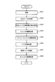
次に、画像処理装置100内で行われる各種信号処理について、図4のフローチャートを用いて詳細に説明する。
まず、撮像を行い(S101)、画像取得部110が、撮像素子200からRAWデータを読み込む(S102)。なお、RAWデータとは、RAW画像(撮像画像)を表すデータである。また、撮像素子200から出力された信号は、プリプロセス回路208によりA/D変換された後に、黒レベル補正処理、ホワイトバランス補正処理等の各種信号処理が施されている。ここでは、このような各種信号処理が行われた後のデータを、RAWデータと呼ぶ。
次に、低ノイズ参照画像生成部120が、C1バンドを参照バンドとして設定し(又はC1バンドの画素を参照バンドの画素として、RAWデータから抽出し)(S103)、C1バンドの画素値に対してノイズ低減処理を行う(S104)。例えばノイズ低減処理は、コアリング処理やメディアンフィルタ処理等により行う。
そして、低ノイズ参照画像生成部120は、ノイズ低減されたC1バンドの画素の補間処理を行い、C1バンドの画素により構成される参照画像を生成する(S105)。なお、補間処理は、後に詳述するガウシアン補間などにより行う。
最後に、補間画像生成部130が、ステップS105で生成された参照画像を用いて各バンド(C2バンド~C5バンド)の補間処理を行い(S106)、処理を終了する。
このように、低ノイズ参照画像生成部120は、撮像画像の画素値のうち、参照画像の参照バンドに対応するカラーフィルタを用いて得られた画素値に対して、ノイズ低減処理を行って、低ノイズ参照画像を生成する。この際に、低ノイズ参照画像生成部120は、ノイズ低減処理を行った後に、撮像画像における参照バンドの画素値の補間処理を行って、低ノイズ参照画像を生成する。すなわち、本実施形態では、参照バンドの画素値の補間処理を行っていない状態で、参照バンドの画素値に対してノイズ低減処理を行う。
よって、補間処理により欠落画素にまでノイズ成分が広がることを抑えること等が可能になる。
次に、各ステップの具体的な内容について詳細に説明する。まず、ステップS104の参照バンドの画素に対するノイズ低減処理について、図5(A)~図5(C)を用いて説明する。
例えば、図5(A)において、図3(A)のカラーフィルタアレイCFA1で参照バンドとして設定されているC1バンドの画素の配置を示す。このように、C1バンドの画素は、市松状に配置されており、この状態でノイズ低減処理を行うことは非常に困難である。
そこで、低ノイズ参照画像生成部120は、撮像画像において、参照画像の参照バンドに対応するカラーフィルタを用いて得られた各画素に対して、第1の座標系から第2の座標系に画素座標の座標変換を行う。例えば、図5(B)のようにxy座標系で配置されている画素を、図5(C)のようにuv座標系で配置されるように、下式(1)を用いて画素座標の変換を行う。なお、図5(A)~図5(C)の例では、第1の座標系がxy座標系であり、第2の座標系がuv座標系である。

この座標変換を行うことにより、例えば、画素座標(x1、y1)の画素は、画素座標(u3、v1)に配置され、画素座標(x1、y3)の画素は、画素座標(u2、v2)に配置され、画素座標(x1、y5)の画素は、画素座標(u1、v3)に配置される。
そして、低ノイズ参照画像生成部120は、座標変換後の参照バンドの各画素の画素値に対して、ノイズ低減処理を行う。例えば、ノイズ低減処理として、uv座標系の画素値に対してコアリング処理やメディアンフィルタ処理を行う。
さらに、低ノイズ参照画像生成部120は、ノイズ低減処理後の各画素に対して、第2の座標系から第1の座標系へ画素座標を座標変換する。つまり、ノイズ低減された画素について、uv座標系から再びxy座標系へと、画素座標の変換を行う。
そして、後に詳述するように、参照バンドの画素値の補間処理を行って、低ノイズ参照画像を生成する。
これにより、参照バンドの画素の補間処理を行っていない状態でノイズ低減処理を行うこと等が可能になる。その結果、前述したように、補間処理によりノイズ成分が周辺画素に広がることを抑えること等が可能になる。
具体的には、低ノイズ参照画像生成部120は、第1の座標系から第2の座標系への座標変換として、画素座標を原点周りで所与の角度だけ回転させる座標変換を行う。
例えば、図5(B)及び図5(C)の例では、画素座標を45度回転させることにより、xy座標系からuv座標系へ座標変換を行う。
これにより、カラーフィルタアレイを、参照バンドの画素値を有する画素が隣り合うようなカラーフィルタアレイに変換すること等が可能になる。
次に、ステップS105の参照バンドの画素の補間処理(参照画像の生成処理)について説明する。
本実施形態では、参照画像の生成処理においてガウシアン補間(GI)を用いる。GIは、画素値を推定したい画素位置周辺の局所的な情報の重み付き平均を、欠落画素の画素値として推定する方法であり、画素位置xpに対する推定画素値SGI(xp)は下記の式(2)のように表される。

ここで、Nxpは画素位置xpの周辺画素の画素位置集合を、xiは画素位置集合Nxp内の任意の画素位置を、S(xi)は画素位置xiの画素値を、M(xi)は画素位置xiのバイナリマスクを、k(xi-xp)は画素位置xpからの距離に基づく重みを、ωGI(xp)は正規化係数、すなわち重みの和を表す。なお、バイナリマスクM(xi)は画素値が存在する場所で1、それ以外で0となる。
例えば、図6(A)の撮像画像IM1に対して上記の補間処理を行うことにより、図6(B)のように、全画素位置にC1バンドの画素値を有する参照画像RIMを生成する。
次に、ステップS106の各バンドの補間処理について説明する。
本実施形態では、参照画像を用いた補間処理として、ガイデッドフィルタ(Guided Filter、ガイデッドイメージフィルタ)を用い、補間処理前の画像に対して補間処理を行って出力画像を生成する。ガイデッドフィルタでは、出力画像は参照画像の線形変換で表されると考える。そして、下記の式(3)に示すように、画素値を推定したい画素位置周辺での局所領域kのコスト関数E(ak、bk)を最小化するように、最小二乗法により係数ak及びbkが算出される。

ここで、iは画素の番号を、kは局所領域の番号を、Iiは参照画像における画素iの画素値を、piは補間処理前の画像における画素iの画素値(信号成分)を、ωkは、補間処理前の画像の局所領域k内において信号成分を有する画素の画素数を、εは所与の平滑化パラメータを、Miは、画素iにおけるバイナリマスクを表す。具体的に、Miは、補間処理前の画像において信号成分を有する画素に対しては1となり、信号成分を有しない画素に対しては0となる。また、ak、bkは、下式(4)で用いるために算出されるべき係数パラメータであり、計算開始時には適当な初期値が用いられる。
そして、全局所領域に対する係数ak及びbkが算出されると、補間対象の画素に対して、下式(4)により出力画素値qiが算出される。本実施形態では、信号成分を有さない画素だけではなく、元々、信号成分(画素値)を有する画素についても、補間対象とする。なお、下式(4)において、|ω|は、局所領域内の全画素数(局所領域数)である。

本実施形態では、図7に示すように、ステップS105で得られた参照画像RIMを使用し、参照バンドであるC1バンドとは異なるバンド(C2バンド~C5バンド)の補間前の画像(IM2~IM5)を、1つずつ補間対象の画像として使用する。このように、参照画像RIMを用いた補間処理を行うことで、ノイズを低減しつつ、参照画像RIMの高周波成分を保持した補間画像(SIM2~SIM5)を生成することが可能である。なお、ステップS106において、C1バンドの補間前の画像IM1についても、同様に補間処理を行って、補間画像SIM1を出力してもよい。ただし、この補間画像SIM1は、ステップS105において生成した参照画像RIMと同じ画像になる。よって、処理量削減を図るため、後の処理では、参照画像RIMを補間画像SIM1として用いることが望ましい。
また、撮像画像において元々、画素値を有する画素については、ステップS106で新たな画素値を算出しないことも可能ではある。しかし、その場合には、元々、画素値を有していた画素と、補間処理を行った画素とにおいて、画素値の差が大きくなり、あたかもノイズが残っているかのような補間画像が生成されてしまうことがある。つまり、斑な補間画像になってしまう。
そこで、前述したように、補間画像生成部130は、撮像画像において画素値を有する画素に対しても、低ノイズ参照画像に基づいて、新たな画素値を算出して、補間画像を生成する。
これにより、元々、画素値を有していた画素と、補間処理を行った画素とにおいて、画素値の差が比較的小さい滑らかな補間画像(マルチバンド画像)を生成すること等が可能になる。
以上のように、ノイズが低減された低ノイズ参照画像を用いることで、出力される補間画像もノイズが低減された画像となる。このことを、図8を用いて説明する。前述した通り、ガイデッドフィルタによる出力画像は、参照画像の線形変換により出力される。例えば、図8の参照画像RIM1が、太枠で区切られる2つの平坦領域(AR1及びAR2)から構成されるものとする。具体的には、平坦領域AR1が第1の色で塗りつぶされた領域であり、平坦領域AR2が、第1の色と異なる第2の色で塗りつぶされた領域であるものとする。そのため、ノイズが含まれていなければ、平坦領域AR1及び平坦領域AR2内の画素の画素値は、各平坦領域内でそれぞれ同じ値になる。しかし、参照画像RIM1にはノイズが含まれているため、平坦領域内の画素値が一定でない。この場合には、入力画像(RAW画像)IIMに対して、ガイデッドフィルタによる補間処理を行うと、補間画像(出力画像)OIM1が得られるが、補間画像(出力画像)OIM1内の画素値qiは、ノイズを引き継いだ値となってしまっている。これは、上式(4)で、参照画像の画素値Iiを定数倍し、さらに定数を加算することにより、出力画素値qiを算出しているためである。
一方で、図8の低ノイズ参照画像RIM2のように、ノイズが無く平坦領域(AR3及びAR4)内の画素値が一定である場合には、補間対象となる入力画像IIMに関わらず、補間画像OIM2のように、平坦領域(AR3及びAR4)内の画素値が(ほぼ)一定のまま出力されることとなる。このようにして、補間対象となる入力画像にノイズが含まれている場合であっても、ノイズが低減された低ノイズ参照画像RIM2を用いることで、ノイズが低減された補間画像OIM2を生成することができる。
以上の処理により、ノイズ低減処理の負担を増やすことなくノイズが低減されたマルチバンド画像を生成することが可能となる。本実施形態では、ノイズが低減された低ノイズ参照画像を用いて、全バンドの補間処理を行うため、ノイズ低減処理を行っていないバンドを補間処理した際でも、参照画像と同様にノイズが低減された補間画像を得ることができ、バンド毎にノイズ低減処理を行う必要がない。さらに、バンド毎にノイズ低減処理を行う場合には、高周波成分を含む領域のボケ具合にバンド間で差が発生し、偽色等のアーティファクトが発生する原因となる場合があるが、本実施形態では高周波成分は参照画像の情報を共有するため、偽色の発生も抑制することが可能となる。
また、前述した例では、ステップS105の補間処理で用いる参照画像として、全てのバンドで同一の画像(例えば7の低ノイズ参照画像RIM)を用いていたが、バンド毎に異なる参照画像を用いてもよい。
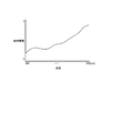
例えば、図9に示すような分光感度特性を持つカラーフィルタアレイを使用する場合について説明する。図9のグラフは、横軸が波長を表し、縦軸が相対感度を表す。まず、図10に示すように、RAW画像からC1バンドの画素値が抽出された画像IM1に対して、ガウシアン補間を行うことにより、C1バンドの参照画像RIMを生成する。
次に、C1バンドと分光感度特性が近いC3バンドの画像IM3と、C4バンドの画像IM4に対しては、C1バンドの参照画像RIMを用いて、補間処理を行って、C3バンドの補間画像SIM3と、C4バンドの補間画像SIM4を生成する。
さらに、C3バンドと分光感度特性が近いC2バンドの画像IM2に対しては、C3バンドの補間画像SIM3を参照画像として用い、補間処理を行って、C2バンドの補間画像SIM2を生成する。C4バンドと分光感度特性が近いC5バンドの画像IM5に対しては、C5バンドの補間画像SIM5を参照画像として用いて、補間処理を行って、C5バンドの補間画像SIM5を生成する。
このように、低ノイズ参照画像生成部120は、マルチバンドのうちの第1のバンドを、参照画像の参照バンドとして選択し、撮像画像において、第1のバンドに対応するカラーフィルタを用いて得られた画素値に対して、ノイズ低減処理を行い、ノイズ低減処理後の第1のバンドの画素値に対して補間処理を行うことにより、低ノイズ参照画像を生成してもよい。前述した図10の例では、第1のバンドはC1バンドであり、低ノイズ参照画像は画像RIMである。
そして、補間画像生成部130は、撮像画像において、低ノイズ参照画像に基づいて、マルチバンドのうちの第2のバンドに対応するカラーフィルタを用いて得られる画素値の補間処理を行い、第2のバンドの補間画像を生成してもよい。前述した図10の例では、第2のバンドはC3バンド及びC4バンドであり、第2のバンドの補間画像は画像SIM3及びSIM4である。
さらに、補間画像生成部130は、撮像画像において、第2のバンドの補間画像に基づいて、マルチバンドのうちの第3のバンドに対応するカラーフィルタを用いて得られる画素値の補間処理を行い、第3のバンドの補間画像を生成してもよい。前述した図10の例では、第3のバンドはC2バンド及びC5バンドであり、第3のバンドの補間画像は画像SIM2及びSIM5である。
このように、分光感度特性に応じて参照画像を切り替えること等が可能である。C1バンドの画像を全バンドの補間処理において参照画像として使用するよりも、分光感度特性に応じて参照画像を切り替える方が効果的である。また、このように参照画像を切り替える場合でも、ノイズが低減されたC1バンドの参照画像RIMを用いて補間処理を行っているために、C3バンドの補間画像SIM3と、C4バンドの補間画像SIM4もノイズが低減されており、同様にC2バンドとC5バンドについてもノイズが低減された補間画像を生成することが可能である。
また、前述した例では、図4のフローチャートに示す通り、参照バンドの画素値に対するノイズ低減処理(S104)は、参照バンドの画素の補間処理(S105)の前に行ったが、図11のフローチャートに示すように、先に参照バンドの画素の補間処理を行ってもよい。
すなわち、低ノイズ参照画像生成部120は、撮像画像の画素値のうち、参照画像の参照バンドに対応するカラーフィルタを用いて得られた画素値の補間処理を行い(S204)、補間処理後の参照バンドの画素値に対して、ノイズ低減処理を行って(S205)、低ノイズ参照画像を生成してもよい。なお、ステップS201~ステップS203及びステップS206については、図4のステップS101~ステップS103及びステップS106と同様であるため、説明を省略する。
これにより、前述した上式(1)を用いる座標変換処理を行う必要がなくなり、より簡便な処理によりノイズ低減を行うこと等が可能になる。ただし、図4のフローチャートの流れで各処理を行った方が、よりノイズを低減した補間画像を生成することが可能である。
また、本実施形態では、図4のステップS103において、予め記憶されているバンドの画素値を参照バンドの画素値として抽出したが、撮像素子200から得られた信号(RAWデータ)から適応的に参照バンドを選択してもよい。参照バンドを適応的に選択することで、より精度の高い補間画像を得ることが可能となる。
例えば、低ノイズ参照画像生成部120は、マルチバンドのうち、撮像画像に映る被写体の色特性と最も相関の強いバンドを、参照画像の参照バンドとして選択してもよい。
具体的には、図3(A)のカラーフィルタアレイCFA1において、サンプル密度が最も高いC1バンドと、被写体の色との相関が低い場合には、C2バンド~C5バンドのうち、被写体の色と相関が最も高いバンドを参照バンドとして選択することで、高周波成分が再現できる。例えば、被写体の色と相関が高いバンドの選択方法としては、ラプラシアンフィルタ等のハイパスフィルタを用いて高周波成分を最も多く含むバンドを選択する方法等がある。
これにより、被写体の色特性に依らず高周波成分を多く含む解像感が高い補間画像を生成すること等が可能となる。
また他にも、撮像画像における輝度値の総和や平均値等が最も高いバンドを選択する方法等もある。すなわち、低ノイズ参照画像生成部120は、撮像画像において、高周波成分及び輝度の少なくとも一方の評価処理を行うことにより、マルチバンドの中から参照画像の参照バンドを選択してもよい。
これにより、被写体の色特性と相関が強いバンドを精度良く選択すること等が可能になる。
また、ノイズ量を考慮する方法でもよい。すなわち、低ノイズ参照画像生成部120は、撮像画像において、マルチバンドのうちの各バンドと撮像画像に映る被写体の色特性との相関と、各バンドにおけるノイズ量の少なくとも一方の評価処理を行うことにより、マルチバンドの中から参照画像の参照バンドを選択してもよい。
例えば、図12のグラフに示すような分光感度特性の照明下で撮像された撮像画像の場合、低ノイズ参照画像生成部120に送られる前のホワイトバランス補正処理により、短波長側に感度を有するバンド(例えばBバンド)のノイズが増幅されてしまう。この場合、被写体の色と相関が高いバンドがBバンドであっても、他のバンドを参照バンドとして選択できるように、被写体の色との相関を評価する相関評価値と、ノイズ量を評価するノイズ評価値との両方を、参照バンドの選択における評価値とする。より具体的には、ノイズ量が予め設定された閾値よりも多いバンドは、被写体の色との相関評価値に関わらず、参照バンドとして選択しないようにする。これにより、高周波成分を最も多く含むバンドを、参照バンドとして選択することができる。
以上のように、撮影する光源により特定のバンドのノイズが増大してしまうシーンでも、高周波成分を多く含む解像感が高い補間画像を生成すること等が可能となる。
3.第2の実施形態
次に、第2の実施形態では、バンド変換部140で3バンド画像を生成し、低ノイズ参照画像生成部120で3バンド画像用のノイズ低減処理を行う例について説明する。
次に、第2の実施形態では、バンド変換部140で3バンド画像を生成し、低ノイズ参照画像生成部120で3バンド画像用のノイズ低減処理を行う例について説明する。
まず、第2の実施形態における画像処理装置100は、図13に示すように、第1の実施形態の構成に加えて、バンド変換部140を含む。
そして、バンド変換部140は、マルチバンドのうちの少なくとも一つのバンドの画素値を、波長帯域が異なる他のバンドの画素値に変換する。
次に、低ノイズ参照画像生成部120は、バンド変換されたバンドの中から、参照画像の参照バンドとして使用するバンドを選択し、バンド変換により得られた参照バンドの画素値に対して、ノイズ低減処理を行って、低ノイズ参照画像を生成する。
具体的には、バンド変換部140は、撮像画像に基づいて、バンド変換を行って、RGB画像を生成する。そして、低ノイズ参照画像生成部120は、ノイズ低減処理として、RGB画像用のノイズ低減処理を行う。
さらに、詳細な具体例を、図13、図14及び図15のフローチャートを用いて説明する。まず、バンド変換部140は、図13に示すようにGバンド補間処理部141と、RBバンド補間処理部142とを含む。
そして、第1の実施形態と同様に、撮像を行い(S301)、RAWデータを取得する(S302)。次に、RAWデータから、RGBバンドの画素値の抽出処理を行う(S303)。なお、マルチバンドの中にRGBに該当するバンドが無い場合には、全バンドの中からRGBのそれぞれに最も近い分光感度特性を有するバンドを、予めバンド変換部140に記憶しておき、分光感度特性が近いバンドの画素値をRGBの画素値に変換して用いる。例えば、図3(A)に示す5バンドのカラーフィルタアレイCFA1の場合には、Gバンドの画素値をC1バンドの画素値から求め、Rバンドの画素値をC5バンドの画素値から求め、Bバンドの画素値をC2バンドの画素値から求める。
そして、図14に示すように、Gバンド補間処理部141では、図4のステップS105と同様に、ガウシアン補間により、画像IM1におけるGバンドの画素値の補間処理を行い、補間画像SIM1を生成する(S304)。
次に、RBバンド補間処理部142では、Gバンド補間処理部141が生成したGバンドの補間画像SIM1を参照画像として、ガイデッドフィルタにより補間処理を行い、画像IM2からRバンドの補間画像SIM2を、画像IM5からBバンドの補間画像SIM5を生成する(S305)。そして、バンド変換部140は、これらの補間画像(SIM1、SIM2及びSIM5)から、RGB画像を生成する。
次に、低ノイズ参照画像生成部120は、バンド変換部140で得られたRGB画像を用いて、RGB画像用のノイズ低減処理を行う(S306)。なお、RGB画像用のノイズ低減処理は、例えば特開2009-49482号公報で開示される手法などを初めとして、様々な手法が開示されており、高精度なノイズ低減効果を得ることが可能である。
そして、補間画像生成部130は、RGBバンドの中から参照バンドとして用いるバンドを選択する(S307)。例えば、低ノイズ参照画像生成部120で、RGBの3バンドの全ての情報を用いるノイズ低減処理を行った場合には、補間画像生成部130は、RGBの3バンドの画素値全てを、参照バンドの画素値として抽出する。
本例では、例えばノイズが低減されたGバンドの補間画像を参照画像RIMとして、残りのC3バンドとC4バンドの画素の補間処理を行い(S308)、取得した全ての補間画像(SIM1~SIM5)に基づいて、マルチバンド画像を生成して、処理を終了する。なお、前述した図7のケースと同様に、本処理においても、C1バンド~C5バンドの全てについて、補間処理をやり直してもよい。
また、バンド変換部140は、必ずしも補間処理前の画像の画素値を、他のバンドの画素値に変換するとは限らない。例えば、マルチバンドのうちRGBに近いバンドの画素を、変換せずに、RGBの画素として用いて、RGB画像用のノイズ低減処理を行ってもよい。例えば、図3(A)に示す5バンドのカラーフィルタアレイCFA1の場合には、Gバンドの画素としてC1バンドの画素を、Rバンドの画素としてC5バンドの画素を、Bバンドの画素としてC2バンドの画素を用いる。
このように、バンド変換処理を行うことにより、撮像素子から直接取得することができないバンドの画素値を参照バンドの画素値として利用すること等が可能となる。
さらに、バンド変換処理により、RGB画像を生成することで、RGB画像用のノイズ低減処理を用いた高精度なノイズ低減を行うこと等が可能となる。
4.第3の実施形態
次に、第3の実施形態について説明する。
次に、第3の実施形態について説明する。
本実施形態の画像処理装置100は、図16に示すように、第2の実施形態のバンド変換部140の代わりに、信号変換部150を含む。
信号変換部150は、撮像画像の各画素値を、輝度信号Y及び色差信号CbCrに変換する。
そして、低ノイズ参照画像生成部120は、輝度信号Y及び色差信号CbCrに対してそれぞれ異なるノイズ低減処理を行って、低ノイズ参照画像を生成する。
例えば、輝度信号Yについては、第1のノイズ低減処理を行い、色差信号CbCrについては、第1のノイズ低減処理よりもノイズ低減効果の高い第2のノイズ低減処理を行う。そして、このように第1のノイズ低減処理と、第2のノイズ低減処理とを行う場合には、信号変換部150でY画像(輝度画像)、CbCr画像(色差画像)を生成し、低ノイズ参照画像生成部120で輝度Y、色差CbCrを参照バンドとして抽出する。
さらに、補間画像生成部130は、ノイズ低減されたY画像及びCbCr画像を、再びGバンドの画像へと変換し、参照画像として使用することが可能である。この場合、低ノイズ参照画像生成部120で、輝度Yのみを参照バンドとして抽出することも可能である。また、ノイズ低減されたY画像を参照画像として使用することも可能である。
これにより、Y画像及びCbCr画像用のノイズ低減処理を用いた高精度なノイズ低減を行うこと等が可能となる。さらに、輝度信号を参照バンドとして使用することで、被写体の色特性に依らず、高周波成分を多く含む解像感が高い補間画像を生成することが可能となる。
なお、本実施形態の画像処理装置及び撮像装置等は、その処理の一部または大部分をプログラムにより実現してもよい。この場合には、CPU等のプロセッサがプログラムを実行することで、本実施形態の画像処理装置及び撮像装置等が実現される。具体的には、非一時的な情報記憶装置に記憶されたプログラムが読み出され、読み出されたプログラムをCPU等のプロセッサが実行する。ここで、情報記憶装置(コンピュータにより読み取り可能な装置)は、プログラムやデータなどを格納するものであり、その機能は、光ディスク(DVD、CD等)、HDD(ハードディスクドライブ)、或いはメモリ(カード型メモリ、ROM等)などにより実現できる。そして、CPU等のプロセッサは、情報記憶装置に格納されるプログラム(データ)に基づいて本実施形態の種々の処理を行う。即ち、情報記憶装置には、本実施形態の各部としてコンピュータ(操作部、処理部、記憶部、出力部を備える装置)を機能させるためのプログラム(各部の処理をコンピュータに実行させるためのプログラム)が記憶される。
また、本実施形態の画像処理装置及び撮像装置等は、プロセッサとメモリを含んでも良い。ここでのプロセッサは、例えばCPU(Central Processing Unit)であってもよい。ただし、プロセッサはCPUに限定されるものではなく、GPU(Graphics Processing Unit)、或いはDSP(Digital Signal Processor)等、各種プロセッサを用いることが可能である。また、プロセッサはASIC(Application Specific Integrated Circuit)によるハードウェア回路でもよい。また、メモリはコンピュータにより読み取り可能な命令を格納するものであり、当該命令がプロセッサにより実行されることで、本実施形態に係る画像処理装置及び撮像装置等の各部が実現されることになる。ここでのメモリは、SRAM(Static Random Access Memory)、DRAM(Dynamic Random Access Memory)などの半導体メモリであってもよいし、レジスタやハードディスク等でもよい。また、ここでの命令は、プログラムを構成する命令セットの命令でもよいし、プロセッサのハードウェア回路に対して操作を指示する命令であってもよい。
以上のように本実施形態について詳細に説明したが、本発明の新規事項および効果から実体的に逸脱しない多くの変形が可能であることは当業者には容易に理解できるであろう。従って、このような変形例はすべて本発明の範囲に含まれるものとする。例えば、明細書又は図面において、少なくとも一度、より広義または同義な異なる用語と共に記載された用語は、明細書又は図面のいかなる箇所においても、その異なる用語に置き換えることができる。また、画像処理装置、撮像装置及びプログラムの構成、動作も本実施形態で説明したものに限定されず、種々の変形実施が可能である。
100 画像処理装置、110 画像取得部、
120 低ノイズ参照画像生成部、130 補間画像生成部、
140 バンド変換部、141 Gバンド補間処理部、
142 RBバンド補間処理部、150 信号変換部、200 撮像素子、
202 撮像レンズ系、203 レンズ駆動機構、204 レンズドライバ、
205 露出制御機構、206 露出制御ドライバ、
207 撮像素子ドライバ、208 プリプロセス回路、
209 メモリカード、210 カードインタフェース(カードI/F)、
211 画像表示系(LCD)、212 操作スイッチ系(操作SW)、
213 操作表示系、214 不揮発性メモリ(EEPROM)、
215 システムコントローラ(CPU)、300 撮像装置
120 低ノイズ参照画像生成部、130 補間画像生成部、
140 バンド変換部、141 Gバンド補間処理部、
142 RBバンド補間処理部、150 信号変換部、200 撮像素子、
202 撮像レンズ系、203 レンズ駆動機構、204 レンズドライバ、
205 露出制御機構、206 露出制御ドライバ、
207 撮像素子ドライバ、208 プリプロセス回路、
209 メモリカード、210 カードインタフェース(カードI/F)、
211 画像表示系(LCD)、212 操作スイッチ系(操作SW)、
213 操作表示系、214 不揮発性メモリ(EEPROM)、
215 システムコントローラ(CPU)、300 撮像装置
Claims (17)
- 4バンド以上(その値を含む)のカラーフィルタがアレイ状に配置されたマルチバンドのカラーフィルタアレイを有する撮像素子を用いて撮像された撮像画像を取得する画像取得部と、
前記撮像画像の画素値の補間処理で用いる参照画像として、ノイズ低減処理が行われた低ノイズ参照画像を生成する低ノイズ参照画像生成部と、
生成された前記低ノイズ参照画像に基づいて、前記マルチバンドのバンド毎に前記補間処理を行って、欠落画素の画素値が補間された補間画像を生成する補間画像生成部と、
を含むことを特徴とする画像処理装置。 - 請求項1において、
前記低ノイズ参照画像生成部は、
前記撮像画像の画素値のうち、前記参照画像の参照バンドに対応するカラーフィルタを用いて得られた画素値に対して、前記ノイズ低減処理を行って、前記低ノイズ参照画像を生成することを特徴とする画像処理装置。 - 請求項1又は2において、
前記補間画像生成部は、
前記撮像画像において画素値を有する画素に対しても、前記低ノイズ参照画像に基づいて、新たな画素値を算出して、前記補間画像を生成することを特徴とする画像処理装置。 - 請求項1又は2において、
前記低ノイズ参照画像生成部は、
前記マルチバンドのうちの第1のバンドを、前記参照画像の参照バンドとして選択し、
前記撮像画像において、前記第1のバンドに対応する前記カラーフィルタを用いて得られた画素値に対して、前記ノイズ低減処理を行って、前記低ノイズ参照画像を生成し、
前記補間画像生成部は、
前記撮像画像において、前記低ノイズ参照画像に基づいて、前記マルチバンドのうちの第2のバンドに対応する前記カラーフィルタを用いて得られる画素値の前記補間処理を行い、前記第2のバンドの前記補間画像を生成し、
前記撮像画像において、前記第2のバンドの前記補間画像に基づいて、前記マルチバンドのうちの第3のバンドに対応する前記カラーフィルタを用いて得られる画素値の前記補間処理を行い、前記第3のバンドの前記補間画像を生成することを特徴とする画像処理装置。 - 請求項1又は2において、
前記低ノイズ参照画像生成部は、
前記撮像画像において、前記参照画像の参照バンドに対応する前記カラーフィルタを用いて得られた各画素に対して、第1の座標系から第2の座標系に画素座標を座標変換し、
座標変換後の前記参照バンドの前記各画素の画素値に対して、前記ノイズ低減処理を行い、
前記ノイズ低減処理後の前記各画素に対して、前記第2の座標系から前記第1の座標系へ前記画素座標を座標変換して、前記低ノイズ参照画像を生成することを特徴とする画像処理装置。 - 請求項5において、
前記低ノイズ参照画像生成部は、
前記第1の座標系から前記第2の座標系への座標変換として、前記画素座標を原点周りで所与の角度だけ回転させる座標変換を行うことを特徴とする画像処理装置。 - 請求項1又は2において、
前記低ノイズ参照画像生成部は、
前記マルチバンドの中でサンプル密度が最も高いバンドを、前記参照画像の参照バンドとして選択することを特徴とする画像処理装置。 - 請求項1又は2において、
前記低ノイズ参照画像生成部は、
前記マルチバンドのうち、前記撮像画像に映る被写体の色特性と最も相関の強いバンドを、前記参照画像の参照バンドとして選択することを特徴とする画像処理装置。 - 請求項1又は2において、
前記低ノイズ参照画像生成部は、
前記撮像画像において、前記マルチバンドのうちの各バンドと前記撮像画像に映る被写体の色特性との相関と、前記各バンドにおけるノイズ量の少なくとも一方の評価処理を行うことにより、前記マルチバンドの中から前記参照画像の参照バンドを選択することを特徴とする画像処理装置。 - 請求項1又は2において、
前記低ノイズ参照画像生成部は、
前記撮像画像において、高周波成分及び輝度の少なくとも一方の評価処理を行うことにより、前記マルチバンドの中から前記参照画像の参照バンドを選択することを特徴とする画像処理装置。 - 請求項1において、
前記低ノイズ参照画像生成部は、
前記撮像画像の画素値のうち、前記参照画像の参照バンドに対応するカラーフィルタを用いて得られた画素値の前記補間処理を行い、前記補間処理後の前記参照バンドの画素値に対して、前記ノイズ低減処理を行って、前記低ノイズ参照画像を生成することを特徴とする画像処理装置。 - 請求項1において、
前記マルチバンドのうちの少なくとも一つのバンドの画素値を、波長帯域が異なる他のバンドの画素値に変換するバンド変換部を含み、
前記低ノイズ参照画像生成部は、
バンド変換されたバンドの中から、前記参照画像の参照バンドとして使用するバンドを選択し、バンド変換により得られた前記参照バンドの画素値に対して、前記ノイズ低減処理を行って、前記低ノイズ参照画像を生成することを特徴とする画像処理装置。 - 請求項12において、
前記バンド変換部は、
前記撮像画像に基づいて、前記バンド変換を行って、RGB画像を生成し、
前記低ノイズ参照画像生成部は、
前記ノイズ低減処理として、RGB画像用のノイズ低減処理を行うことを特徴とする画像処理装置。 - 請求項1において、
前記撮像画像の各画素値を、輝度信号及び色差信号に変換する信号変換部を含み、
前記低ノイズ参照画像生成部は、
前記輝度信号及び前記色差信号に対してそれぞれ異なる前記ノイズ低減処理を行って、前記低ノイズ参照画像を生成することを特徴とする画像処理装置。 - 請求項1又は2に記載の画像処理装置を含むことを特徴とする撮像装置。
- 4バンド以上(その値を含む)のカラーフィルタがアレイ状に配置されたマルチバンドのカラーフィルタアレイを有する撮像素子を用いて撮像された撮像画像を取得する画像取得部と、
前記撮像画像の画素値の補間処理で用いる参照画像として、ノイズ低減処理が行われた低ノイズ参照画像を生成する低ノイズ参照画像生成部と、
生成された前記低ノイズ参照画像に基づいて、前記マルチバンドのバンド毎に前記補間処理を行って、欠落画素の画素値が補間された補間画像を生成する補間画像生成部として、
コンピュータを機能させることを特徴とするプログラム。 - 4バンド以上(その値を含む)のカラーフィルタがアレイ状に配置されたマルチバンドのカラーフィルタアレイを有する撮像素子を用いて撮像された撮像画像を取得し、
前記撮像画像の画素値の補間処理で用いる参照画像として、ノイズ低減処理が行われた低ノイズ参照画像を生成し、
生成された前記低ノイズ参照画像に基づいて、前記マルチバンドのバンド毎に前記補間処理を行って、欠落画素の画素値が補間された補間画像を生成することを特徴とする画像処理方法。
Priority Applications (1)
| Application Number | Priority Date | Filing Date | Title |
|---|---|---|---|
| US15/187,405 US9843782B2 (en) | 2013-12-24 | 2016-06-20 | Interpolation device, storage medium, and method with multi-band color filter and noise reduced reference image |
Applications Claiming Priority (2)
| Application Number | Priority Date | Filing Date | Title |
|---|---|---|---|
| JP2013265472A JP5771677B2 (ja) | 2013-12-24 | 2013-12-24 | 画像処理装置、撮像装置、プログラム及び画像処理方法 |
| JP2013-265472 | 2013-12-24 |
Related Child Applications (1)
| Application Number | Title | Priority Date | Filing Date |
|---|---|---|---|
| US15/187,405 Continuation US9843782B2 (en) | 2013-12-24 | 2016-06-20 | Interpolation device, storage medium, and method with multi-band color filter and noise reduced reference image |
Publications (1)
| Publication Number | Publication Date |
|---|---|
| WO2015098243A1 true WO2015098243A1 (ja) | 2015-07-02 |
Family
ID=53478122
Family Applications (1)
| Application Number | Title | Priority Date | Filing Date |
|---|---|---|---|
| PCT/JP2014/077286 Ceased WO2015098243A1 (ja) | 2013-12-24 | 2014-10-14 | 画像処理装置、撮像装置、プログラム及び画像処理方法 |
Country Status (3)
| Country | Link |
|---|---|
| US (1) | US9843782B2 (ja) |
| JP (1) | JP5771677B2 (ja) |
| WO (1) | WO2015098243A1 (ja) |
Families Citing this family (6)
| Publication number | Priority date | Publication date | Assignee | Title |
|---|---|---|---|---|
| WO2016063316A1 (ja) * | 2014-10-23 | 2016-04-28 | 国立大学法人東京工業大学 | 画像処理ユニット、撮像装置、画像処理プログラム、および画像処理方法 |
| KR101700928B1 (ko) * | 2015-11-06 | 2017-02-01 | 인천대학교 산학협력단 | 다중 방향성 가중 보간 및 유도필터에 기초한 베이어 패턴 영상의 디모자이킹 방법 및 장치 |
| EP3429197B1 (en) * | 2016-03-09 | 2020-05-06 | Sony Corporation | Image processing apparatus, imaging apparatus, image processing method, and program |
| CN111093459A (zh) * | 2017-10-04 | 2020-05-01 | 奥林巴斯株式会社 | 内窥镜装置、图像处理方法以及程序 |
| CN108399605B (zh) * | 2018-01-09 | 2021-07-06 | 网宿科技股份有限公司 | 图片处理方法、终端设备及计算机可读存储介质 |
| CN113812137B (zh) * | 2019-05-16 | 2024-03-15 | 三菱电机株式会社 | 图像处理装置和方法、图像读取装置和记录介质 |
Citations (3)
| Publication number | Priority date | Publication date | Assignee | Title |
|---|---|---|---|---|
| JP2012222704A (ja) * | 2011-04-12 | 2012-11-12 | Olympus Corp | 撮像装置 |
| JP2012239038A (ja) * | 2011-05-11 | 2012-12-06 | Tokyo Institute Of Technology | 画像処理システム |
| JP2013093754A (ja) * | 2011-10-26 | 2013-05-16 | Olympus Corp | 撮像装置 |
Family Cites Families (4)
| Publication number | Priority date | Publication date | Assignee | Title |
|---|---|---|---|---|
| JP3745948B2 (ja) | 2000-08-25 | 2006-02-15 | シャープ株式会社 | 画像処理装置およびデジタルカメラ |
| JP4740912B2 (ja) | 2007-08-13 | 2011-08-03 | オリンパス株式会社 | 画像処理装置、撮像装置、画像処理プログラム、画像処理方法 |
| JP5045421B2 (ja) | 2007-12-21 | 2012-10-10 | ソニー株式会社 | 撮像装置、色ノイズ低減方法および色ノイズ低減プログラム |
| US8295631B2 (en) | 2010-01-29 | 2012-10-23 | Eastman Kodak Company | Iteratively denoising color filter array images |
-
2013
- 2013-12-24 JP JP2013265472A patent/JP5771677B2/ja active Active
-
2014
- 2014-10-14 WO PCT/JP2014/077286 patent/WO2015098243A1/ja not_active Ceased
-
2016
- 2016-06-20 US US15/187,405 patent/US9843782B2/en active Active
Patent Citations (3)
| Publication number | Priority date | Publication date | Assignee | Title |
|---|---|---|---|---|
| JP2012222704A (ja) * | 2011-04-12 | 2012-11-12 | Olympus Corp | 撮像装置 |
| JP2012239038A (ja) * | 2011-05-11 | 2012-12-06 | Tokyo Institute Of Technology | 画像処理システム |
| JP2013093754A (ja) * | 2011-10-26 | 2013-05-16 | Olympus Corp | 撮像装置 |
Also Published As
| Publication number | Publication date |
|---|---|
| JP5771677B2 (ja) | 2015-09-02 |
| JP2015122634A (ja) | 2015-07-02 |
| US20160309131A1 (en) | 2016-10-20 |
| US9843782B2 (en) | 2017-12-12 |
Similar Documents
| Publication | Publication Date | Title |
|---|---|---|
| JP5047048B2 (ja) | 画像処理装置、撮像装置、制御方法、プログラム、及び記憶媒体 | |
| US9179113B2 (en) | Image processing device, and image processing method, and program | |
| JP5349790B2 (ja) | 画像処理装置、画像処理方法、及びプログラム | |
| JP4501855B2 (ja) | 画像信号処理装置、撮像装置、および画像信号処理方法、並びにコンピュータ・プログラム | |
| JP5284537B2 (ja) | 画像処理装置、画像処理方法、画像処理プログラム、およびそれを用いた撮像装置 | |
| JP5546229B2 (ja) | 画像処理方法、画像処理装置、撮像装置および画像処理プログラム | |
| EP1931130B1 (en) | Image processing apparatus, image processing method, and program | |
| JP5771677B2 (ja) | 画像処理装置、撮像装置、プログラム及び画像処理方法 | |
| WO2011122284A1 (ja) | 画像処理装置、およびそれを用いた撮像装置 | |
| CN106162132A (zh) | 图像处理设备及其控制方法 | |
| JP2011123589A5 (ja) | ||
| KR20130033304A (ko) | 화상처리장치 및 방법 | |
| WO2011121760A1 (ja) | 画像処理装置、およびそれを用いた撮像装置 | |
| JP4730082B2 (ja) | 画像信号処理装置、撮像装置、および画像信号処理方法、並びにコンピュータ・プログラム | |
| JP5541205B2 (ja) | 画像処理装置、撮像装置、画像処理プログラムおよび画像処理方法 | |
| JP2013055623A (ja) | 画像処理装置、および画像処理方法、情報記録媒体、並びにプログラム | |
| WO2017216903A1 (ja) | 画像処理装置、画像処理方法および画像処理プログラム | |
| JP5047055B2 (ja) | 画像処理装置、撮像装置及び画像処理方法 | |
| JP4963598B2 (ja) | 画像処理装置及び撮像装置及び画像処理方法及びプログラム | |
| JP5020615B2 (ja) | 画像処理装置及び撮像装置及び画像処理方法及びプログラム | |
| WO2014115453A1 (ja) | 画像処理装置、撮像装置、画像処理方法及びプログラム | |
| JP5274697B2 (ja) | 画像処理装置及び画像処理方法 | |
| JP2010178226A (ja) | 撮像装置、色収差抑制方法、色収差抑制回路及びプログラム | |
| JP6238673B2 (ja) | 画像処理装置、撮像装置、撮像システム、画像処理方法、画像処理プログラム、および、記憶媒体 | |
| JP4478981B2 (ja) | 色雑音低減手法およびカラー撮像装置 |
Legal Events
| Date | Code | Title | Description |
|---|---|---|---|
| 121 | Ep: the epo has been informed by wipo that ep was designated in this application |
Ref document number: 14874438 Country of ref document: EP Kind code of ref document: A1 |
|
| NENP | Non-entry into the national phase |
Ref country code: DE |
|
| 122 | Ep: pct application non-entry in european phase |
Ref document number: 14874438 Country of ref document: EP Kind code of ref document: A1 |