WO2015097994A1 - Power supply apparatus of vehicle - Google Patents
Power supply apparatus of vehicle Download PDFInfo
- Publication number
- WO2015097994A1 WO2015097994A1 PCT/JP2014/006023 JP2014006023W WO2015097994A1 WO 2015097994 A1 WO2015097994 A1 WO 2015097994A1 JP 2014006023 W JP2014006023 W JP 2014006023W WO 2015097994 A1 WO2015097994 A1 WO 2015097994A1
- Authority
- WO
- WIPO (PCT)
- Prior art keywords
- voltage
- voltage step
- converter
- mode
- battery
- Prior art date
- Legal status (The legal status is an assumption and is not a legal conclusion. Google has not performed a legal analysis and makes no representation as to the accuracy of the status listed.)
- Ceased
Links
Images



Classifications
-
- B—PERFORMING OPERATIONS; TRANSPORTING
- B60—VEHICLES IN GENERAL
- B60L—PROPULSION OF ELECTRICALLY-PROPELLED VEHICLES; SUPPLYING ELECTRIC POWER FOR AUXILIARY EQUIPMENT OF ELECTRICALLY-PROPELLED VEHICLES; ELECTRODYNAMIC BRAKE SYSTEMS FOR VEHICLES IN GENERAL; MAGNETIC SUSPENSION OR LEVITATION FOR VEHICLES; MONITORING OPERATING VARIABLES OF ELECTRICALLY-PROPELLED VEHICLES; ELECTRIC SAFETY DEVICES FOR ELECTRICALLY-PROPELLED VEHICLES
- B60L1/00—Supplying electric power to auxiliary equipment of vehicles
- B60L1/003—Supplying electric power to auxiliary equipment of vehicles to auxiliary motors, e.g. for pumps, compressors
-
- B—PERFORMING OPERATIONS; TRANSPORTING
- B60—VEHICLES IN GENERAL
- B60L—PROPULSION OF ELECTRICALLY-PROPELLED VEHICLES; SUPPLYING ELECTRIC POWER FOR AUXILIARY EQUIPMENT OF ELECTRICALLY-PROPELLED VEHICLES; ELECTRODYNAMIC BRAKE SYSTEMS FOR VEHICLES IN GENERAL; MAGNETIC SUSPENSION OR LEVITATION FOR VEHICLES; MONITORING OPERATING VARIABLES OF ELECTRICALLY-PROPELLED VEHICLES; ELECTRIC SAFETY DEVICES FOR ELECTRICALLY-PROPELLED VEHICLES
- B60L1/00—Supplying electric power to auxiliary equipment of vehicles
- B60L1/02—Supplying electric power to auxiliary equipment of vehicles to electric heating circuits
-
- B—PERFORMING OPERATIONS; TRANSPORTING
- B60—VEHICLES IN GENERAL
- B60L—PROPULSION OF ELECTRICALLY-PROPELLED VEHICLES; SUPPLYING ELECTRIC POWER FOR AUXILIARY EQUIPMENT OF ELECTRICALLY-PROPELLED VEHICLES; ELECTRODYNAMIC BRAKE SYSTEMS FOR VEHICLES IN GENERAL; MAGNETIC SUSPENSION OR LEVITATION FOR VEHICLES; MONITORING OPERATING VARIABLES OF ELECTRICALLY-PROPELLED VEHICLES; ELECTRIC SAFETY DEVICES FOR ELECTRICALLY-PROPELLED VEHICLES
- B60L15/00—Methods, circuits, or devices for controlling the traction-motor speed of electrically-propelled vehicles
- B60L15/007—Physical arrangements or structures of drive train converters specially adapted for the propulsion motors of electric vehicles
-
- B—PERFORMING OPERATIONS; TRANSPORTING
- B60—VEHICLES IN GENERAL
- B60L—PROPULSION OF ELECTRICALLY-PROPELLED VEHICLES; SUPPLYING ELECTRIC POWER FOR AUXILIARY EQUIPMENT OF ELECTRICALLY-PROPELLED VEHICLES; ELECTRODYNAMIC BRAKE SYSTEMS FOR VEHICLES IN GENERAL; MAGNETIC SUSPENSION OR LEVITATION FOR VEHICLES; MONITORING OPERATING VARIABLES OF ELECTRICALLY-PROPELLED VEHICLES; ELECTRIC SAFETY DEVICES FOR ELECTRICALLY-PROPELLED VEHICLES
- B60L15/00—Methods, circuits, or devices for controlling the traction-motor speed of electrically-propelled vehicles
- B60L15/20—Methods, circuits, or devices for controlling the traction-motor speed of electrically-propelled vehicles for control of the vehicle or its driving motor to achieve a desired performance, e.g. speed, torque, programmed variation of speed
- B60L15/2045—Methods, circuits, or devices for controlling the traction-motor speed of electrically-propelled vehicles for control of the vehicle or its driving motor to achieve a desired performance, e.g. speed, torque, programmed variation of speed for optimising the use of energy
-
- B—PERFORMING OPERATIONS; TRANSPORTING
- B60—VEHICLES IN GENERAL
- B60L—PROPULSION OF ELECTRICALLY-PROPELLED VEHICLES; SUPPLYING ELECTRIC POWER FOR AUXILIARY EQUIPMENT OF ELECTRICALLY-PROPELLED VEHICLES; ELECTRODYNAMIC BRAKE SYSTEMS FOR VEHICLES IN GENERAL; MAGNETIC SUSPENSION OR LEVITATION FOR VEHICLES; MONITORING OPERATING VARIABLES OF ELECTRICALLY-PROPELLED VEHICLES; ELECTRIC SAFETY DEVICES FOR ELECTRICALLY-PROPELLED VEHICLES
- B60L50/00—Electric propulsion with power supplied within the vehicle
- B60L50/10—Electric propulsion with power supplied within the vehicle using propulsion power supplied by engine-driven generators, e.g. generators driven by combustion engines
- B60L50/16—Electric propulsion with power supplied within the vehicle using propulsion power supplied by engine-driven generators, e.g. generators driven by combustion engines with provision for separate direct mechanical propulsion
-
- B—PERFORMING OPERATIONS; TRANSPORTING
- B60—VEHICLES IN GENERAL
- B60L—PROPULSION OF ELECTRICALLY-PROPELLED VEHICLES; SUPPLYING ELECTRIC POWER FOR AUXILIARY EQUIPMENT OF ELECTRICALLY-PROPELLED VEHICLES; ELECTRODYNAMIC BRAKE SYSTEMS FOR VEHICLES IN GENERAL; MAGNETIC SUSPENSION OR LEVITATION FOR VEHICLES; MONITORING OPERATING VARIABLES OF ELECTRICALLY-PROPELLED VEHICLES; ELECTRIC SAFETY DEVICES FOR ELECTRICALLY-PROPELLED VEHICLES
- B60L50/00—Electric propulsion with power supplied within the vehicle
- B60L50/50—Electric propulsion with power supplied within the vehicle using propulsion power supplied by batteries or fuel cells
- B60L50/60—Electric propulsion with power supplied within the vehicle using propulsion power supplied by batteries or fuel cells using power supplied by batteries
- B60L50/61—Electric propulsion with power supplied within the vehicle using propulsion power supplied by batteries or fuel cells using power supplied by batteries by batteries charged by engine-driven generators, e.g. series hybrid electric vehicles
-
- B—PERFORMING OPERATIONS; TRANSPORTING
- B60—VEHICLES IN GENERAL
- B60L—PROPULSION OF ELECTRICALLY-PROPELLED VEHICLES; SUPPLYING ELECTRIC POWER FOR AUXILIARY EQUIPMENT OF ELECTRICALLY-PROPELLED VEHICLES; ELECTRODYNAMIC BRAKE SYSTEMS FOR VEHICLES IN GENERAL; MAGNETIC SUSPENSION OR LEVITATION FOR VEHICLES; MONITORING OPERATING VARIABLES OF ELECTRICALLY-PROPELLED VEHICLES; ELECTRIC SAFETY DEVICES FOR ELECTRICALLY-PROPELLED VEHICLES
- B60L50/00—Electric propulsion with power supplied within the vehicle
- B60L50/50—Electric propulsion with power supplied within the vehicle using propulsion power supplied by batteries or fuel cells
- B60L50/60—Electric propulsion with power supplied within the vehicle using propulsion power supplied by batteries or fuel cells using power supplied by batteries
- B60L50/66—Arrangements of batteries
-
- B—PERFORMING OPERATIONS; TRANSPORTING
- B60—VEHICLES IN GENERAL
- B60L—PROPULSION OF ELECTRICALLY-PROPELLED VEHICLES; SUPPLYING ELECTRIC POWER FOR AUXILIARY EQUIPMENT OF ELECTRICALLY-PROPELLED VEHICLES; ELECTRODYNAMIC BRAKE SYSTEMS FOR VEHICLES IN GENERAL; MAGNETIC SUSPENSION OR LEVITATION FOR VEHICLES; MONITORING OPERATING VARIABLES OF ELECTRICALLY-PROPELLED VEHICLES; ELECTRIC SAFETY DEVICES FOR ELECTRICALLY-PROPELLED VEHICLES
- B60L58/00—Methods or circuit arrangements for monitoring or controlling batteries or fuel cells, specially adapted for electric vehicles
- B60L58/10—Methods or circuit arrangements for monitoring or controlling batteries or fuel cells, specially adapted for electric vehicles for monitoring or controlling batteries
- B60L58/12—Methods or circuit arrangements for monitoring or controlling batteries or fuel cells, specially adapted for electric vehicles for monitoring or controlling batteries responding to state of charge [SoC]
-
- B—PERFORMING OPERATIONS; TRANSPORTING
- B60—VEHICLES IN GENERAL
- B60L—PROPULSION OF ELECTRICALLY-PROPELLED VEHICLES; SUPPLYING ELECTRIC POWER FOR AUXILIARY EQUIPMENT OF ELECTRICALLY-PROPELLED VEHICLES; ELECTRODYNAMIC BRAKE SYSTEMS FOR VEHICLES IN GENERAL; MAGNETIC SUSPENSION OR LEVITATION FOR VEHICLES; MONITORING OPERATING VARIABLES OF ELECTRICALLY-PROPELLED VEHICLES; ELECTRIC SAFETY DEVICES FOR ELECTRICALLY-PROPELLED VEHICLES
- B60L58/00—Methods or circuit arrangements for monitoring or controlling batteries or fuel cells, specially adapted for electric vehicles
- B60L58/10—Methods or circuit arrangements for monitoring or controlling batteries or fuel cells, specially adapted for electric vehicles for monitoring or controlling batteries
- B60L58/18—Methods or circuit arrangements for monitoring or controlling batteries or fuel cells, specially adapted for electric vehicles for monitoring or controlling batteries of two or more battery modules
- B60L58/21—Methods or circuit arrangements for monitoring or controlling batteries or fuel cells, specially adapted for electric vehicles for monitoring or controlling batteries of two or more battery modules having the same nominal voltage
-
- B—PERFORMING OPERATIONS; TRANSPORTING
- B60—VEHICLES IN GENERAL
- B60L—PROPULSION OF ELECTRICALLY-PROPELLED VEHICLES; SUPPLYING ELECTRIC POWER FOR AUXILIARY EQUIPMENT OF ELECTRICALLY-PROPELLED VEHICLES; ELECTRODYNAMIC BRAKE SYSTEMS FOR VEHICLES IN GENERAL; MAGNETIC SUSPENSION OR LEVITATION FOR VEHICLES; MONITORING OPERATING VARIABLES OF ELECTRICALLY-PROPELLED VEHICLES; ELECTRIC SAFETY DEVICES FOR ELECTRICALLY-PROPELLED VEHICLES
- B60L58/00—Methods or circuit arrangements for monitoring or controlling batteries or fuel cells, specially adapted for electric vehicles
- B60L58/10—Methods or circuit arrangements for monitoring or controlling batteries or fuel cells, specially adapted for electric vehicles for monitoring or controlling batteries
- B60L58/24—Methods or circuit arrangements for monitoring or controlling batteries or fuel cells, specially adapted for electric vehicles for monitoring or controlling batteries for controlling the temperature of batteries
- B60L58/25—Methods or circuit arrangements for monitoring or controlling batteries or fuel cells, specially adapted for electric vehicles for monitoring or controlling batteries for controlling the temperature of batteries by controlling the electric load
-
- B—PERFORMING OPERATIONS; TRANSPORTING
- B60—VEHICLES IN GENERAL
- B60L—PROPULSION OF ELECTRICALLY-PROPELLED VEHICLES; SUPPLYING ELECTRIC POWER FOR AUXILIARY EQUIPMENT OF ELECTRICALLY-PROPELLED VEHICLES; ELECTRODYNAMIC BRAKE SYSTEMS FOR VEHICLES IN GENERAL; MAGNETIC SUSPENSION OR LEVITATION FOR VEHICLES; MONITORING OPERATING VARIABLES OF ELECTRICALLY-PROPELLED VEHICLES; ELECTRIC SAFETY DEVICES FOR ELECTRICALLY-PROPELLED VEHICLES
- B60L7/00—Electrodynamic brake systems for vehicles in general
- B60L7/10—Dynamic electric regenerative braking
- B60L7/12—Dynamic electric regenerative braking for vehicles propelled by DC motors
-
- B—PERFORMING OPERATIONS; TRANSPORTING
- B60—VEHICLES IN GENERAL
- B60L—PROPULSION OF ELECTRICALLY-PROPELLED VEHICLES; SUPPLYING ELECTRIC POWER FOR AUXILIARY EQUIPMENT OF ELECTRICALLY-PROPELLED VEHICLES; ELECTRODYNAMIC BRAKE SYSTEMS FOR VEHICLES IN GENERAL; MAGNETIC SUSPENSION OR LEVITATION FOR VEHICLES; MONITORING OPERATING VARIABLES OF ELECTRICALLY-PROPELLED VEHICLES; ELECTRIC SAFETY DEVICES FOR ELECTRICALLY-PROPELLED VEHICLES
- B60L7/00—Electrodynamic brake systems for vehicles in general
- B60L7/10—Dynamic electric regenerative braking
- B60L7/14—Dynamic electric regenerative braking for vehicles propelled by AC motors
-
- B—PERFORMING OPERATIONS; TRANSPORTING
- B60—VEHICLES IN GENERAL
- B60L—PROPULSION OF ELECTRICALLY-PROPELLED VEHICLES; SUPPLYING ELECTRIC POWER FOR AUXILIARY EQUIPMENT OF ELECTRICALLY-PROPELLED VEHICLES; ELECTRODYNAMIC BRAKE SYSTEMS FOR VEHICLES IN GENERAL; MAGNETIC SUSPENSION OR LEVITATION FOR VEHICLES; MONITORING OPERATING VARIABLES OF ELECTRICALLY-PROPELLED VEHICLES; ELECTRIC SAFETY DEVICES FOR ELECTRICALLY-PROPELLED VEHICLES
- B60L2210/00—Converter types
- B60L2210/10—DC to DC converters
- B60L2210/12—Buck converters
-
- B—PERFORMING OPERATIONS; TRANSPORTING
- B60—VEHICLES IN GENERAL
- B60L—PROPULSION OF ELECTRICALLY-PROPELLED VEHICLES; SUPPLYING ELECTRIC POWER FOR AUXILIARY EQUIPMENT OF ELECTRICALLY-PROPELLED VEHICLES; ELECTRODYNAMIC BRAKE SYSTEMS FOR VEHICLES IN GENERAL; MAGNETIC SUSPENSION OR LEVITATION FOR VEHICLES; MONITORING OPERATING VARIABLES OF ELECTRICALLY-PROPELLED VEHICLES; ELECTRIC SAFETY DEVICES FOR ELECTRICALLY-PROPELLED VEHICLES
- B60L2210/00—Converter types
- B60L2210/10—DC to DC converters
- B60L2210/14—Boost converters
-
- B—PERFORMING OPERATIONS; TRANSPORTING
- B60—VEHICLES IN GENERAL
- B60L—PROPULSION OF ELECTRICALLY-PROPELLED VEHICLES; SUPPLYING ELECTRIC POWER FOR AUXILIARY EQUIPMENT OF ELECTRICALLY-PROPELLED VEHICLES; ELECTRODYNAMIC BRAKE SYSTEMS FOR VEHICLES IN GENERAL; MAGNETIC SUSPENSION OR LEVITATION FOR VEHICLES; MONITORING OPERATING VARIABLES OF ELECTRICALLY-PROPELLED VEHICLES; ELECTRIC SAFETY DEVICES FOR ELECTRICALLY-PROPELLED VEHICLES
- B60L2210/00—Converter types
- B60L2210/30—AC to DC converters
-
- B—PERFORMING OPERATIONS; TRANSPORTING
- B60—VEHICLES IN GENERAL
- B60L—PROPULSION OF ELECTRICALLY-PROPELLED VEHICLES; SUPPLYING ELECTRIC POWER FOR AUXILIARY EQUIPMENT OF ELECTRICALLY-PROPELLED VEHICLES; ELECTRODYNAMIC BRAKE SYSTEMS FOR VEHICLES IN GENERAL; MAGNETIC SUSPENSION OR LEVITATION FOR VEHICLES; MONITORING OPERATING VARIABLES OF ELECTRICALLY-PROPELLED VEHICLES; ELECTRIC SAFETY DEVICES FOR ELECTRICALLY-PROPELLED VEHICLES
- B60L2210/00—Converter types
- B60L2210/40—DC to AC converters
-
- B—PERFORMING OPERATIONS; TRANSPORTING
- B60—VEHICLES IN GENERAL
- B60L—PROPULSION OF ELECTRICALLY-PROPELLED VEHICLES; SUPPLYING ELECTRIC POWER FOR AUXILIARY EQUIPMENT OF ELECTRICALLY-PROPELLED VEHICLES; ELECTRODYNAMIC BRAKE SYSTEMS FOR VEHICLES IN GENERAL; MAGNETIC SUSPENSION OR LEVITATION FOR VEHICLES; MONITORING OPERATING VARIABLES OF ELECTRICALLY-PROPELLED VEHICLES; ELECTRIC SAFETY DEVICES FOR ELECTRICALLY-PROPELLED VEHICLES
- B60L2240/00—Control parameters of input or output; Target parameters
- B60L2240/10—Vehicle control parameters
- B60L2240/12—Speed
-
- B—PERFORMING OPERATIONS; TRANSPORTING
- B60—VEHICLES IN GENERAL
- B60L—PROPULSION OF ELECTRICALLY-PROPELLED VEHICLES; SUPPLYING ELECTRIC POWER FOR AUXILIARY EQUIPMENT OF ELECTRICALLY-PROPELLED VEHICLES; ELECTRODYNAMIC BRAKE SYSTEMS FOR VEHICLES IN GENERAL; MAGNETIC SUSPENSION OR LEVITATION FOR VEHICLES; MONITORING OPERATING VARIABLES OF ELECTRICALLY-PROPELLED VEHICLES; ELECTRIC SAFETY DEVICES FOR ELECTRICALLY-PROPELLED VEHICLES
- B60L2240/00—Control parameters of input or output; Target parameters
- B60L2240/10—Vehicle control parameters
- B60L2240/14—Acceleration
-
- B—PERFORMING OPERATIONS; TRANSPORTING
- B60—VEHICLES IN GENERAL
- B60L—PROPULSION OF ELECTRICALLY-PROPELLED VEHICLES; SUPPLYING ELECTRIC POWER FOR AUXILIARY EQUIPMENT OF ELECTRICALLY-PROPELLED VEHICLES; ELECTRODYNAMIC BRAKE SYSTEMS FOR VEHICLES IN GENERAL; MAGNETIC SUSPENSION OR LEVITATION FOR VEHICLES; MONITORING OPERATING VARIABLES OF ELECTRICALLY-PROPELLED VEHICLES; ELECTRIC SAFETY DEVICES FOR ELECTRICALLY-PROPELLED VEHICLES
- B60L2240/00—Control parameters of input or output; Target parameters
- B60L2240/10—Vehicle control parameters
- B60L2240/34—Cabin temperature
-
- B—PERFORMING OPERATIONS; TRANSPORTING
- B60—VEHICLES IN GENERAL
- B60L—PROPULSION OF ELECTRICALLY-PROPELLED VEHICLES; SUPPLYING ELECTRIC POWER FOR AUXILIARY EQUIPMENT OF ELECTRICALLY-PROPELLED VEHICLES; ELECTRODYNAMIC BRAKE SYSTEMS FOR VEHICLES IN GENERAL; MAGNETIC SUSPENSION OR LEVITATION FOR VEHICLES; MONITORING OPERATING VARIABLES OF ELECTRICALLY-PROPELLED VEHICLES; ELECTRIC SAFETY DEVICES FOR ELECTRICALLY-PROPELLED VEHICLES
- B60L2240/00—Control parameters of input or output; Target parameters
- B60L2240/10—Vehicle control parameters
- B60L2240/36—Temperature of vehicle components or parts
-
- B—PERFORMING OPERATIONS; TRANSPORTING
- B60—VEHICLES IN GENERAL
- B60L—PROPULSION OF ELECTRICALLY-PROPELLED VEHICLES; SUPPLYING ELECTRIC POWER FOR AUXILIARY EQUIPMENT OF ELECTRICALLY-PROPELLED VEHICLES; ELECTRODYNAMIC BRAKE SYSTEMS FOR VEHICLES IN GENERAL; MAGNETIC SUSPENSION OR LEVITATION FOR VEHICLES; MONITORING OPERATING VARIABLES OF ELECTRICALLY-PROPELLED VEHICLES; ELECTRIC SAFETY DEVICES FOR ELECTRICALLY-PROPELLED VEHICLES
- B60L2240/00—Control parameters of input or output; Target parameters
- B60L2240/40—Drive Train control parameters
- B60L2240/42—Drive Train control parameters related to electric machines
- B60L2240/421—Speed
-
- B—PERFORMING OPERATIONS; TRANSPORTING
- B60—VEHICLES IN GENERAL
- B60L—PROPULSION OF ELECTRICALLY-PROPELLED VEHICLES; SUPPLYING ELECTRIC POWER FOR AUXILIARY EQUIPMENT OF ELECTRICALLY-PROPELLED VEHICLES; ELECTRODYNAMIC BRAKE SYSTEMS FOR VEHICLES IN GENERAL; MAGNETIC SUSPENSION OR LEVITATION FOR VEHICLES; MONITORING OPERATING VARIABLES OF ELECTRICALLY-PROPELLED VEHICLES; ELECTRIC SAFETY DEVICES FOR ELECTRICALLY-PROPELLED VEHICLES
- B60L2240/00—Control parameters of input or output; Target parameters
- B60L2240/40—Drive Train control parameters
- B60L2240/42—Drive Train control parameters related to electric machines
- B60L2240/423—Torque
-
- B—PERFORMING OPERATIONS; TRANSPORTING
- B60—VEHICLES IN GENERAL
- B60L—PROPULSION OF ELECTRICALLY-PROPELLED VEHICLES; SUPPLYING ELECTRIC POWER FOR AUXILIARY EQUIPMENT OF ELECTRICALLY-PROPELLED VEHICLES; ELECTRODYNAMIC BRAKE SYSTEMS FOR VEHICLES IN GENERAL; MAGNETIC SUSPENSION OR LEVITATION FOR VEHICLES; MONITORING OPERATING VARIABLES OF ELECTRICALLY-PROPELLED VEHICLES; ELECTRIC SAFETY DEVICES FOR ELECTRICALLY-PROPELLED VEHICLES
- B60L2240/00—Control parameters of input or output; Target parameters
- B60L2240/40—Drive Train control parameters
- B60L2240/42—Drive Train control parameters related to electric machines
- B60L2240/425—Temperature
-
- B—PERFORMING OPERATIONS; TRANSPORTING
- B60—VEHICLES IN GENERAL
- B60L—PROPULSION OF ELECTRICALLY-PROPELLED VEHICLES; SUPPLYING ELECTRIC POWER FOR AUXILIARY EQUIPMENT OF ELECTRICALLY-PROPELLED VEHICLES; ELECTRODYNAMIC BRAKE SYSTEMS FOR VEHICLES IN GENERAL; MAGNETIC SUSPENSION OR LEVITATION FOR VEHICLES; MONITORING OPERATING VARIABLES OF ELECTRICALLY-PROPELLED VEHICLES; ELECTRIC SAFETY DEVICES FOR ELECTRICALLY-PROPELLED VEHICLES
- B60L2240/00—Control parameters of input or output; Target parameters
- B60L2240/40—Drive Train control parameters
- B60L2240/42—Drive Train control parameters related to electric machines
- B60L2240/427—Voltage
-
- B—PERFORMING OPERATIONS; TRANSPORTING
- B60—VEHICLES IN GENERAL
- B60L—PROPULSION OF ELECTRICALLY-PROPELLED VEHICLES; SUPPLYING ELECTRIC POWER FOR AUXILIARY EQUIPMENT OF ELECTRICALLY-PROPELLED VEHICLES; ELECTRODYNAMIC BRAKE SYSTEMS FOR VEHICLES IN GENERAL; MAGNETIC SUSPENSION OR LEVITATION FOR VEHICLES; MONITORING OPERATING VARIABLES OF ELECTRICALLY-PROPELLED VEHICLES; ELECTRIC SAFETY DEVICES FOR ELECTRICALLY-PROPELLED VEHICLES
- B60L2240/00—Control parameters of input or output; Target parameters
- B60L2240/40—Drive Train control parameters
- B60L2240/42—Drive Train control parameters related to electric machines
- B60L2240/429—Current
-
- B—PERFORMING OPERATIONS; TRANSPORTING
- B60—VEHICLES IN GENERAL
- B60L—PROPULSION OF ELECTRICALLY-PROPELLED VEHICLES; SUPPLYING ELECTRIC POWER FOR AUXILIARY EQUIPMENT OF ELECTRICALLY-PROPELLED VEHICLES; ELECTRODYNAMIC BRAKE SYSTEMS FOR VEHICLES IN GENERAL; MAGNETIC SUSPENSION OR LEVITATION FOR VEHICLES; MONITORING OPERATING VARIABLES OF ELECTRICALLY-PROPELLED VEHICLES; ELECTRIC SAFETY DEVICES FOR ELECTRICALLY-PROPELLED VEHICLES
- B60L2240/00—Control parameters of input or output; Target parameters
- B60L2240/40—Drive Train control parameters
- B60L2240/48—Drive Train control parameters related to transmissions
- B60L2240/485—Temperature
-
- B—PERFORMING OPERATIONS; TRANSPORTING
- B60—VEHICLES IN GENERAL
- B60L—PROPULSION OF ELECTRICALLY-PROPELLED VEHICLES; SUPPLYING ELECTRIC POWER FOR AUXILIARY EQUIPMENT OF ELECTRICALLY-PROPELLED VEHICLES; ELECTRODYNAMIC BRAKE SYSTEMS FOR VEHICLES IN GENERAL; MAGNETIC SUSPENSION OR LEVITATION FOR VEHICLES; MONITORING OPERATING VARIABLES OF ELECTRICALLY-PROPELLED VEHICLES; ELECTRIC SAFETY DEVICES FOR ELECTRICALLY-PROPELLED VEHICLES
- B60L2240/00—Control parameters of input or output; Target parameters
- B60L2240/40—Drive Train control parameters
- B60L2240/52—Drive Train control parameters related to converters
- B60L2240/526—Operating parameters
-
- B—PERFORMING OPERATIONS; TRANSPORTING
- B60—VEHICLES IN GENERAL
- B60L—PROPULSION OF ELECTRICALLY-PROPELLED VEHICLES; SUPPLYING ELECTRIC POWER FOR AUXILIARY EQUIPMENT OF ELECTRICALLY-PROPELLED VEHICLES; ELECTRODYNAMIC BRAKE SYSTEMS FOR VEHICLES IN GENERAL; MAGNETIC SUSPENSION OR LEVITATION FOR VEHICLES; MONITORING OPERATING VARIABLES OF ELECTRICALLY-PROPELLED VEHICLES; ELECTRIC SAFETY DEVICES FOR ELECTRICALLY-PROPELLED VEHICLES
- B60L2240/00—Control parameters of input or output; Target parameters
- B60L2240/40—Drive Train control parameters
- B60L2240/52—Drive Train control parameters related to converters
- B60L2240/527—Voltage
-
- B—PERFORMING OPERATIONS; TRANSPORTING
- B60—VEHICLES IN GENERAL
- B60L—PROPULSION OF ELECTRICALLY-PROPELLED VEHICLES; SUPPLYING ELECTRIC POWER FOR AUXILIARY EQUIPMENT OF ELECTRICALLY-PROPELLED VEHICLES; ELECTRODYNAMIC BRAKE SYSTEMS FOR VEHICLES IN GENERAL; MAGNETIC SUSPENSION OR LEVITATION FOR VEHICLES; MONITORING OPERATING VARIABLES OF ELECTRICALLY-PROPELLED VEHICLES; ELECTRIC SAFETY DEVICES FOR ELECTRICALLY-PROPELLED VEHICLES
- B60L2240/00—Control parameters of input or output; Target parameters
- B60L2240/40—Drive Train control parameters
- B60L2240/52—Drive Train control parameters related to converters
- B60L2240/529—Current
-
- B—PERFORMING OPERATIONS; TRANSPORTING
- B60—VEHICLES IN GENERAL
- B60L—PROPULSION OF ELECTRICALLY-PROPELLED VEHICLES; SUPPLYING ELECTRIC POWER FOR AUXILIARY EQUIPMENT OF ELECTRICALLY-PROPELLED VEHICLES; ELECTRODYNAMIC BRAKE SYSTEMS FOR VEHICLES IN GENERAL; MAGNETIC SUSPENSION OR LEVITATION FOR VEHICLES; MONITORING OPERATING VARIABLES OF ELECTRICALLY-PROPELLED VEHICLES; ELECTRIC SAFETY DEVICES FOR ELECTRICALLY-PROPELLED VEHICLES
- B60L2240/00—Control parameters of input or output; Target parameters
- B60L2240/40—Drive Train control parameters
- B60L2240/54—Drive Train control parameters related to batteries
- B60L2240/545—Temperature
-
- B—PERFORMING OPERATIONS; TRANSPORTING
- B60—VEHICLES IN GENERAL
- B60L—PROPULSION OF ELECTRICALLY-PROPELLED VEHICLES; SUPPLYING ELECTRIC POWER FOR AUXILIARY EQUIPMENT OF ELECTRICALLY-PROPELLED VEHICLES; ELECTRODYNAMIC BRAKE SYSTEMS FOR VEHICLES IN GENERAL; MAGNETIC SUSPENSION OR LEVITATION FOR VEHICLES; MONITORING OPERATING VARIABLES OF ELECTRICALLY-PROPELLED VEHICLES; ELECTRIC SAFETY DEVICES FOR ELECTRICALLY-PROPELLED VEHICLES
- B60L2240/00—Control parameters of input or output; Target parameters
- B60L2240/40—Drive Train control parameters
- B60L2240/54—Drive Train control parameters related to batteries
- B60L2240/547—Voltage
-
- B—PERFORMING OPERATIONS; TRANSPORTING
- B60—VEHICLES IN GENERAL
- B60L—PROPULSION OF ELECTRICALLY-PROPELLED VEHICLES; SUPPLYING ELECTRIC POWER FOR AUXILIARY EQUIPMENT OF ELECTRICALLY-PROPELLED VEHICLES; ELECTRODYNAMIC BRAKE SYSTEMS FOR VEHICLES IN GENERAL; MAGNETIC SUSPENSION OR LEVITATION FOR VEHICLES; MONITORING OPERATING VARIABLES OF ELECTRICALLY-PROPELLED VEHICLES; ELECTRIC SAFETY DEVICES FOR ELECTRICALLY-PROPELLED VEHICLES
- B60L2240/00—Control parameters of input or output; Target parameters
- B60L2240/40—Drive Train control parameters
- B60L2240/54—Drive Train control parameters related to batteries
- B60L2240/549—Current
-
- B—PERFORMING OPERATIONS; TRANSPORTING
- B60—VEHICLES IN GENERAL
- B60L—PROPULSION OF ELECTRICALLY-PROPELLED VEHICLES; SUPPLYING ELECTRIC POWER FOR AUXILIARY EQUIPMENT OF ELECTRICALLY-PROPELLED VEHICLES; ELECTRODYNAMIC BRAKE SYSTEMS FOR VEHICLES IN GENERAL; MAGNETIC SUSPENSION OR LEVITATION FOR VEHICLES; MONITORING OPERATING VARIABLES OF ELECTRICALLY-PROPELLED VEHICLES; ELECTRIC SAFETY DEVICES FOR ELECTRICALLY-PROPELLED VEHICLES
- B60L2240/00—Control parameters of input or output; Target parameters
- B60L2240/80—Time limits
-
- B—PERFORMING OPERATIONS; TRANSPORTING
- B60—VEHICLES IN GENERAL
- B60L—PROPULSION OF ELECTRICALLY-PROPELLED VEHICLES; SUPPLYING ELECTRIC POWER FOR AUXILIARY EQUIPMENT OF ELECTRICALLY-PROPELLED VEHICLES; ELECTRODYNAMIC BRAKE SYSTEMS FOR VEHICLES IN GENERAL; MAGNETIC SUSPENSION OR LEVITATION FOR VEHICLES; MONITORING OPERATING VARIABLES OF ELECTRICALLY-PROPELLED VEHICLES; ELECTRIC SAFETY DEVICES FOR ELECTRICALLY-PROPELLED VEHICLES
- B60L2250/00—Driver interactions
- B60L2250/26—Driver interactions by pedal actuation
-
- B—PERFORMING OPERATIONS; TRANSPORTING
- B60—VEHICLES IN GENERAL
- B60L—PROPULSION OF ELECTRICALLY-PROPELLED VEHICLES; SUPPLYING ELECTRIC POWER FOR AUXILIARY EQUIPMENT OF ELECTRICALLY-PROPELLED VEHICLES; ELECTRODYNAMIC BRAKE SYSTEMS FOR VEHICLES IN GENERAL; MAGNETIC SUSPENSION OR LEVITATION FOR VEHICLES; MONITORING OPERATING VARIABLES OF ELECTRICALLY-PROPELLED VEHICLES; ELECTRIC SAFETY DEVICES FOR ELECTRICALLY-PROPELLED VEHICLES
- B60L2260/00—Operating Modes
- B60L2260/20—Drive modes; Transition between modes
- B60L2260/26—Transition between different drive modes
-
- B—PERFORMING OPERATIONS; TRANSPORTING
- B60—VEHICLES IN GENERAL
- B60L—PROPULSION OF ELECTRICALLY-PROPELLED VEHICLES; SUPPLYING ELECTRIC POWER FOR AUXILIARY EQUIPMENT OF ELECTRICALLY-PROPELLED VEHICLES; ELECTRODYNAMIC BRAKE SYSTEMS FOR VEHICLES IN GENERAL; MAGNETIC SUSPENSION OR LEVITATION FOR VEHICLES; MONITORING OPERATING VARIABLES OF ELECTRICALLY-PROPELLED VEHICLES; ELECTRIC SAFETY DEVICES FOR ELECTRICALLY-PROPELLED VEHICLES
- B60L2260/00—Operating Modes
- B60L2260/40—Control modes
- B60L2260/50—Control modes by future state prediction
- B60L2260/54—Energy consumption estimation
-
- B—PERFORMING OPERATIONS; TRANSPORTING
- B60—VEHICLES IN GENERAL
- B60L—PROPULSION OF ELECTRICALLY-PROPELLED VEHICLES; SUPPLYING ELECTRIC POWER FOR AUXILIARY EQUIPMENT OF ELECTRICALLY-PROPELLED VEHICLES; ELECTRODYNAMIC BRAKE SYSTEMS FOR VEHICLES IN GENERAL; MAGNETIC SUSPENSION OR LEVITATION FOR VEHICLES; MONITORING OPERATING VARIABLES OF ELECTRICALLY-PROPELLED VEHICLES; ELECTRIC SAFETY DEVICES FOR ELECTRICALLY-PROPELLED VEHICLES
- B60L2270/00—Problem solutions or means not otherwise provided for
- B60L2270/20—Inrush current reduction, i.e. avoiding high currents when connecting the battery
-
- Y—GENERAL TAGGING OF NEW TECHNOLOGICAL DEVELOPMENTS; GENERAL TAGGING OF CROSS-SECTIONAL TECHNOLOGIES SPANNING OVER SEVERAL SECTIONS OF THE IPC; TECHNICAL SUBJECTS COVERED BY FORMER USPC CROSS-REFERENCE ART COLLECTIONS [XRACs] AND DIGESTS
- Y02—TECHNOLOGIES OR APPLICATIONS FOR MITIGATION OR ADAPTATION AGAINST CLIMATE CHANGE
- Y02T—CLIMATE CHANGE MITIGATION TECHNOLOGIES RELATED TO TRANSPORTATION
- Y02T10/00—Road transport of goods or passengers
- Y02T10/60—Other road transportation technologies with climate change mitigation effect
- Y02T10/62—Hybrid vehicles
-
- Y—GENERAL TAGGING OF NEW TECHNOLOGICAL DEVELOPMENTS; GENERAL TAGGING OF CROSS-SECTIONAL TECHNOLOGIES SPANNING OVER SEVERAL SECTIONS OF THE IPC; TECHNICAL SUBJECTS COVERED BY FORMER USPC CROSS-REFERENCE ART COLLECTIONS [XRACs] AND DIGESTS
- Y02—TECHNOLOGIES OR APPLICATIONS FOR MITIGATION OR ADAPTATION AGAINST CLIMATE CHANGE
- Y02T—CLIMATE CHANGE MITIGATION TECHNOLOGIES RELATED TO TRANSPORTATION
- Y02T10/00—Road transport of goods or passengers
- Y02T10/60—Other road transportation technologies with climate change mitigation effect
- Y02T10/64—Electric machine technologies in electromobility
-
- Y—GENERAL TAGGING OF NEW TECHNOLOGICAL DEVELOPMENTS; GENERAL TAGGING OF CROSS-SECTIONAL TECHNOLOGIES SPANNING OVER SEVERAL SECTIONS OF THE IPC; TECHNICAL SUBJECTS COVERED BY FORMER USPC CROSS-REFERENCE ART COLLECTIONS [XRACs] AND DIGESTS
- Y02—TECHNOLOGIES OR APPLICATIONS FOR MITIGATION OR ADAPTATION AGAINST CLIMATE CHANGE
- Y02T—CLIMATE CHANGE MITIGATION TECHNOLOGIES RELATED TO TRANSPORTATION
- Y02T10/00—Road transport of goods or passengers
- Y02T10/60—Other road transportation technologies with climate change mitigation effect
- Y02T10/70—Energy storage systems for electromobility, e.g. batteries
-
- Y—GENERAL TAGGING OF NEW TECHNOLOGICAL DEVELOPMENTS; GENERAL TAGGING OF CROSS-SECTIONAL TECHNOLOGIES SPANNING OVER SEVERAL SECTIONS OF THE IPC; TECHNICAL SUBJECTS COVERED BY FORMER USPC CROSS-REFERENCE ART COLLECTIONS [XRACs] AND DIGESTS
- Y02—TECHNOLOGIES OR APPLICATIONS FOR MITIGATION OR ADAPTATION AGAINST CLIMATE CHANGE
- Y02T—CLIMATE CHANGE MITIGATION TECHNOLOGIES RELATED TO TRANSPORTATION
- Y02T10/00—Road transport of goods or passengers
- Y02T10/60—Other road transportation technologies with climate change mitigation effect
- Y02T10/7072—Electromobility specific charging systems or methods for batteries, ultracapacitors, supercapacitors or double-layer capacitors
-
- Y—GENERAL TAGGING OF NEW TECHNOLOGICAL DEVELOPMENTS; GENERAL TAGGING OF CROSS-SECTIONAL TECHNOLOGIES SPANNING OVER SEVERAL SECTIONS OF THE IPC; TECHNICAL SUBJECTS COVERED BY FORMER USPC CROSS-REFERENCE ART COLLECTIONS [XRACs] AND DIGESTS
- Y02—TECHNOLOGIES OR APPLICATIONS FOR MITIGATION OR ADAPTATION AGAINST CLIMATE CHANGE
- Y02T—CLIMATE CHANGE MITIGATION TECHNOLOGIES RELATED TO TRANSPORTATION
- Y02T10/00—Road transport of goods or passengers
- Y02T10/60—Other road transportation technologies with climate change mitigation effect
- Y02T10/72—Electric energy management in electromobility
Definitions
- the present invention relates to a power supply apparatus of a vehicle.
- a vehicle that has a motor capable of driving drive wheels and is configured so that a voltage of a battery is stepped up and supplied to an inverter which drives the motor.
- Japanese Patent Laying-Open No. 2010-172139 discloses that a target value of a voltage stepped up by a voltage step-up converter is limited to a smaller value in the case where the battery temperature is lower than a predetermined value, as compared with a target value thereof in the case where the battery temperature is higher than the predetermined value. Under this control, an overvoltage can be prevented, when the battery temperature is low, from being applied to a smoothing capacitor which smoothes the stepped-up voltage.
- intermittent voltage step-up control may be performed by intermittently operating and stopping a voltage step-up converter to thereby reduce an electric power loss due to switching of the voltage step-up converter.
- this control is performed, current flowing through the voltage step-up converter and current flowing from/into a battery are also quickly switched between a state of being flown and a state of not being flown.
- ECU Electronic Control Unit
- data of electric current used for the control may be measured in slow cycles, resulting in a failure to be able to precisely observe changes of the electric current. In this case, there is a possibility that the electric current controllability is deteriorated.
- a low battery temperature is generally accompanied by a large internal resistance and thus by a large battery voltage variation with an electric current variation. Therefore, if the intermittent voltage step-up control is performed in the condition that the battery temperature is low and the electric current controllability has been deteriorated, the battery voltage varies to a large extent in the condition that the controllability has been deteriorated. Due to this, the battery voltage may not be controlled so that it falls within a limit voltage range and the battery voltage may go beyond a limit voltage value. As a result, there arises a possibility that the battery performance is deteriorated.
- An object of the present invention is to provide a power supply apparatus of a vehicle that is capable of ensuring an effect of reducing an electric power loss by the intermittent voltage step-up control and still capable of preventing the battery performance from being deteriorated.
- the present invention is a power supply apparatus of a vehicle that includes: a power storage device; a voltage step-up converter stepping up a voltage of the power storage device and supplying the stepped-up voltage to an electrical load of the vehicle; and a control device controlling the voltage step-up converter in a continuous voltage step-up mode in which the voltage step-up converter is continuously operated and an intermittent voltage step-up mode in which the voltage step-up converter is intermittently operated.
- the control device inhibits the voltage step-up converter from operating in the intermittent voltage step-up mode, when a temperature of the power storage device is equal to or less than a predetermined value.
- the voltage step-up converter is controlled in the intermittent voltage step-up mode to thereby reduce an electric power loss.
- the voltage step-up converter is inhibited from operating in the intermittent voltage step-up mode, to thereby ensure that a limit voltage value, which is determined in terms of protection of the power storage device, will not be exceeded.
- the predetermined value is determined based on a temperature of the power storage device having a voltage which is an upper limit voltage or a lower limit voltage of the power storage device, in a condition that an absolute value of current flowing through the voltage step-up converter is a maximum value while the voltage step-up converter operates in the intermittent voltage step-up mode.
- the threshold value of the temperature is determined in this way, and accordingly the intermittent voltage step-up mode is permitted when the temperature falls within an appropriate temperature range.
- an electrically powered vehicle can ensure an effect of reducing an electric power loss by the intermittent voltage step-up control and can still prevent the battery performance from being deteriorated.
- Fig. 1 is a block diagram for illustrating an example configuration of a hybrid vehicle shown as a typical example of the electrically powered vehicle according to an embodiment of the present invention.
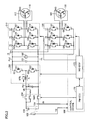
- Fig. 2 is a circuit diagram illustrating an example configuration of an electrical system of the hybrid vehicle shown in Fig. 1.
- Fig. 3 is a flowchart showing a procedure of voltage step-up control by a converter 200.
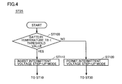
- Fig. 4 is a flowchart showing details of step ST25 in the flowchart of Fig. 3.
- Fig. 5 is a waveform diagram for illustrating operations in a continuous voltage step-up mode and an intermittent voltage step-up mode.
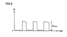
- Fig. 6 is a waveform diagram for illustrating battery current IB in the case where converter 200 is controlled in the intermittent voltage step-up mode.
- Fig. 1 is a block diagram for illustrating an example configuration of a hybrid vehicle shown as a typical example of the electrically powered vehicle according to the embodiment of the present invention.
- the hybrid vehicle includes an engine 100 corresponding to "internal combustion engine," a first MG (Motor Generator) 110, a second MG 120, a power split device 130, a reduction gear 140, a battery 150, drive wheels 160, and a control device 500.
- Control device 500 is configured to include a PM (Power Management) - ECU (Electronic Control Unit) 170 and an MG (Motor Generator) - ECU 172.
- the hybrid vehicle is caused to run by a drive force from at least one of engine 100 and second MG 120.
- Engine 100, first MG 110, and second MG 120 are coupled to each other through power split device 130.
- Power split device 130 is typically configured as a planetary gear mechanism.
- Power split device 130 includes a sun gear 131 which is an externally-toothed gear, a ring gear 132 which is an internally-toothed gear arranged concentrically with sun gear 131, a plurality of pinion gears 133 meshing with sun gear 131 and with ring gear 132, and a carrier 134.
- Carrier 134 is configured to hold a plurality of pinion gears 133 so that they can rotate on respective axes and also revolve.
- Power split device 130 splits motive power generated by engine 100 into two paths. One is a path for driving drive wheels 160 through reduction gear 140. The other is a path for generating electric power by driving first MG 110.
- First MG 110 and second MG 120 are each typically a three-phase AC rotating electric machine configured in the form of a permanent-magnet motor.
- First MG 110 mainly operates as "electric generator” and is capable of generating electric power from a drive force which is supplied from engine 100 and split by power split device 130.
- the electric power generated by first MG 110 is used differently depending on the condition in which the vehicle is running and the condition of the SOC (State Of Charge) of battery 150. Regarding this electric power, its voltage is thereafter adjusted by a converter, which will be described later herein, and stored in battery 150.
- first MG 110 can also operate as an electric motor as a result of torque control.
- Second MG 120 mainly operates as "electric motor” and is driven by means of at least one of the electric power stored in battery 150 and the electric power generated by first MG 110.
- the motive power generated by second MG 120 is transmitted to a driveshaft 135 and further transmitted through reduction gear 140 to drive wheels 160.
- second MG 120 assists engine 100 or causes the vehicle to run by the drive force from second MG 120.
- second MG 120 When the hybrid vehicle is regeneratively braked, second MG 120 is driven by drive wheels 160 through reduction gear 140. In this case, second MG 120 operates as an electric generator. Thus, second MG 120 serves as a regenerative brake converting braking energy into electric power. The electric power generated by second MG 120 is stored in battery 150.
- Battery 150 is a battery pack made up of a plurality of battery modules connected in series, the battery modules each being made up of a plurality of battery cells integrated into the battery module.
- the voltage of battery 150 is approximately 200 V for example.
- Battery 150 can be charged with electric power generated by first MG 110 or second MG 120.
- the temperature, the voltage, and the current of battery 150 are detected by a battery sensor 152.
- a temperature sensor, a voltage sensor, and a current sensor are herein collectively referred to as battery sensor 152.
- PM-ECU 170 and MG-ECU 172 are each configured to have a CPU (Central Processing Unit) and a memory (not shown) incorporated therein, and configured to perform operations based on values detected respectively by the sensors, through software processing in accordance with a map and a program stored in the memory.
- a CPU Central Processing Unit
- a memory not shown
- PM-ECU 170 and MG-ECU 172 may be configured to perform a predetermined mathematical operation and/or a predetermined logical operation through hardware processing by a dedicated electronic circuit or the like.
- Engine 100 is controlled in accordance with an operational command value from PM-ECU 170.
- First MG 110, second MG 120, converter 200, and inverters 210, 220 are controlled by MG-ECU 172.
- PM-ECU 170 and MG-ECU 172 are connected to each other so that they can bidirectionally communicate with each other.
- PM-ECU 170 and MG-ECU 172 are configured as separate ECUs in the present embodiment, a single ECU incorporating respective functions of these ECUs may be provided.
- Fig. 2 is a circuit diagram illustrating an example configuration of an electrical system of the hybrid vehicle shown in Fig. 1.
- the electrical system of the hybrid vehicle includes converter 200, inverter 210 associated with first MG 110, inverter 220 associated with second MG 120, an SMR (System Main Relay) 230, and capacitors C1, C2.
- converter 200 inverter 210 associated with first MG 110
- inverter 220 associated with second MG 120
- SMR System Main Relay
- Converter 200 includes two power semiconductor switching elements Q1, Q2 (also referred to simply as “switching element” hereinafter) connected in series, diodes D1, D2 provided in association with switching elements Q1, Q2, respectively, and a reactor L.
- Switching elements Q1, Q2 are connected in series between a positive line PL2 and a ground line GL which is connected to a negative electrode of battery 150.
- the collector of switching element Q1 is connected to positive line PL2 and the emitter of switching element Q2 is connected to ground line GL.
- Diodes D1, D2 are connected in anti-parallel with switching elements Q1, Q2, respectively.
- Switching element Q1 and diode D1 constitute an upper arm of converter 200 and switching element Q2 and diode D2 constitute a lower arm of converter 200.
- any of IGBT (Insulated Gate Bipolar Transistor), power MOS (Metal Oxide Semiconductor) transistor, power bipolar transistor and the like can appropriately be used. ON/OFF of each of switching elements Q1, Q2 is controlled by a switching control signal from MG-ECU 172.
- Reactor L has one end connected to a positive line PL1 which is connected to a positive electrode of battery 150, and the other end connected to a connection node of switching elements Q1, Q2, namely a connection point between the emitter of switching element Q1 and the collector of switching element Q2.
- Capacitor C2 is connected between positive line PL2 and ground line GL. Capacitor C2 smoothes an AC component of a voltage variation between positive line PL2 and ground line GL. Capacitor C1 is connected between positive line PL1 and ground line GL. Capacitor C1 smoothes an AC component of a voltage variation between positive line PL1 and ground line GL.
- reactor current Current IL flowing in reactor L (hereinafter reactor current) is detected by a current sensor SEIL.
- a voltage sensor 180 detects a voltage across terminals of capacitor C2 that is an output voltage of converter 200, namely detects a voltage VH (system voltage) between positive line PL2 and ground line GL, and outputs the detected value to MG-ECU 172.
- VH system voltage
- Converter 200, inverter 210, and inverter 220 are electrically connected to each other through positive line PL2 and ground line GL.
- converter 200 steps up a DC voltage VB (voltage across the opposite terminals of capacitor C1) that is supplied from battery 150, and supplies system voltage VH generated by the voltage step-up to inverters 210, 220. More specifically, in response to a switching control signal from MG-ECU 172, an ON period of switching element Q1 and an ON period of switching element Q2 are alternated, and a voltage step-up ratio is determined depending on a ratio between these ON periods.
- DC voltage VB voltage across the opposite terminals of capacitor C1
- converter 200 steps down system voltage VH which is supplied through capacitor C2 from inverters 210, 220 to charge battery 150 with the voltage. More specifically, in response to a switching control signal from MG-ECU 172, a period in which only switching element Q1 is ON and a period in which both switching elements Q1, Q2 are OFF are alternated, and a voltage step-down ratio is determined depending on the duty ratio of the ON period.
- switching element Q1 When the voltage step-up/step-down operation of converter 200 is stopped, switching element Q1 is fixed in an ON state and switching element Q2 is fixed in an OFF state.
- Inverter 210 is configured in the form of a common three-phase inverter, and includes a U phase arm 15, a V phase arm 16, and a W phase arm 17. Arms 15 to 17 include switching elements Q3 to Q8 and anti-parallel diodes D3 to D8.
- inverter 210 controls current or voltage of each phase coil of first MG 110 so that first MG 110 operates in accordance with an operational command value (typically torque command value) which is set for generating a drive force (vehicle drive torque, electric power generation torque, or the like) required for the vehicle to run.
- an operational command value typically torque command value
- inverter 210 performs bidirectional DC/AC power conversion between positive line PL2 and first MG 110.
- Inverter 220 is configured in the form of a common three-phase inverter, like inverter 210.
- inverter 220 controls current or voltage of each phase coil of second MG 120 so that second MG 120 operates in accordance with an operational command value (typically torque command value) which is set for generating a drive force (vehicle drive torque, regenerative braking torque, or the like) required for the vehicle to run.
- an operational command value typically torque command value
- inverter 220 performs bidirectional DC/AC power conversion between positive line PL2 and second MG 120.
- PM-ECU 170 calculates a torque command value TR1 for first MG 110 and a torque command value TR2 for second MG 120, based on an accelerator pedal position Acc and a speed V of the hybrid vehicle.
- MG-ECU 172 calculates an optimum value (target value) of output voltage (system voltage) VH of converter 200, namely a command voltage VH*, based on torque command value TR1 for first MG 110 and torque command value TR2 for second MG 120 that are calculated by PM-ECU 170 as well as a motor rotational speed MRN1 of first MG 110 and a motor rotational speed MRN2 of second MG 120.
- MG-ECU 172 calculates, based on output voltage VH of converter 200 that is detected by voltage sensor 180 and command voltage VH*, a duty ratio for controlling output voltage VH so that voltage VH is equal to command voltage VH*, and accordingly controls converter 200.
- the MG-ECU 172 controls converter 200 by setting the converter in one of a continuous voltage step-up mode and an intermittent voltage step-up mode.
- the continuous voltage step-up mode is a mode in which converter 200 performs a voltage step-up operation without stopping.
- the intermittent voltage step-up mode is a mode in which converter 200 intermittently repeats a voltage step-up operation and stoppage of the voltage step-up operation.
- switching elements Q1, Q2 are switched between an ON state and an OFF state.
- switching element Q1 is fixed in the ON state and switching element Q2 is fixed in the OFF state.
- converter 200 does not step up the voltage in the continuous voltage step-up mode and the fact that converter 200 stops voltage step-up in the intermittent voltage step-up mode are different from each other in terms of the following respect.
- the continuous voltage step-up mode is a mode in which converter 200 is operating without stopping. While converter 200 is operating, the voltage of battery 150 is supplied to inverters 210, 220 through converter 200.
- operations in the continuous voltage step-up mode also includes an operation in which the duty ratio is 1 and converter 200 supplies the voltage of battery 150 as it is to inverters 210, 220 without stepping up the voltage.
- converter 200 stops voltage step-up in the intermittent voltage step-up mode, the voltage of battery 150 is not supplied through converter 200 to inverters 210, 220.
- Fig. 3 is a flowchart showing a procedure of voltage step-up control by converter 200.
- Fig. 5 is a waveform diagram for illustrating operations in the continuous voltage step-up mode and the intermittent voltage step-up mode.
- Fig. 5 (a) is a chart showing output voltage (system voltage) VH of converter 200 in the continuous voltage step-up mode and the intermittent voltage step-up mode.
- Fig. 5 (b) is a chart showing reactor current IL in the continuous voltage step-up mode and the intermittent voltage step-up mode. Although reactor current IL is actually caused to vary by switching of converter 200, Fig. 5 (b) shows the reactor current whose varying component due to switching is smoothed.
- Fig. 5 (c) is a chart showing a voltage step-up power loss LP due to switching in the continuous voltage step-up mode and the intermittent voltage step-up mode.
- control device 500 sets converter 200 in the continuous voltage step-up mode.
- Converter 200 performs the voltage step-up operation without stopping the voltage step-up operation.
- control device 500 causes the process to proceed to step ST25.
- control device 500 checks a battery condition in order to determine whether to set the converter in the intermittent voltage step-up mode or not.
- Fig. 4 is a flowchart showing details of step ST25 of the flowchart in Fig. 3.
- control device 500 in response to the start of the process of step ST25, obtains a battery temperature TB from battery sensor 152 and determines whether or not battery temperature TB is lower than a threshold value in step ST100.
- control device 500 causes the process to proceed to step ST110 and determines that the intermittent voltage step-up mode should be inhibited, and causes the process to return to step ST10 of the flowchart in Fig. 2.
- converter 200 is set in the continuous voltage step-up mode to operate.
- control device 500 causes the process to proceed to step ST120 and determines that the intermittent voltage step-up mode should be permitted, and causes the process to proceed to step ST30 of the flowchart in Fig. 2.
- converter 200 is set in the intermittent voltage step-up mode to operate.
- control device 500 sets converter 200 in the intermittent voltage step-up mode.
- control device 500 first causes the voltage step-up operation of converter 200 to be stopped (see time (1) in Fig. 5 for example).
- control device 500 causes the process to proceed to step ST50.
- control device 500 causes converter 200 to restart the voltage step-up operation (see time (2) in Fig. 5 for example).
- control device 500 causes the process to proceed to step ST70.
- control device 500 causes the voltage step-up operation by converter 200 to be stopped (see time (3) in Fig. 5 for example).
- the process is performed again from step ST40.
- control device 500 causes the process to proceed to step ST90 to set converter 200 in the continuous voltage step-up mode.
- Converter 200 performs the voltage step-up operation without stopping (see time (4) in Fig. 5 for example).
- time (4) in Fig. 5 it is shown that command voltage VH* has been increased and reactor current IL begins to increase.
- Fig. 5 (c) shows by what amount voltage step-up power loss LP is reduced in a set of one period in which voltage step-up is stopped and one subsequent period in which voltage step-up is performed, in the intermittent voltage step-up mode.
- An area P3 of a region enclosed by a line which represents a reference power loss BS and a line which represents voltage step-up power loss LP and is located higher than the line of reference power loss BS is the sum of voltage step-up power losses LP larger than the voltage step-up power loss in the continuous voltage step-up mode.
- An area P0 of a region enclosed by the line which represents reference power loss BS and the line which represents voltage step-up power loss LP and is located lower than the line of reference power loss BS is the sum of voltage step-up power losses LP smaller than the voltage step-up power loss in the continuous voltage step-up mode.
- the converter can be set in the intermittent voltage step-up mode to thereby reduce the voltage step-up power loss.
- a longer period in which the voltage step-up is stopped produces a greater effect of reducing the loss.
- the intermittent voltage step-up mode is changed to the continuous voltage step-up mode.
- the continuous voltage step-up mode is changed to the intermittent voltage step-up mode.
- TH1 > TH2 it is preferable that TH1 > TH2 is met.
- Whether to switch the mode to the intermittent voltage step-up mode or not is determined by checking the battery condition in step ST25, because if converter 200 is controlled in the intermittent voltage step-up mode while the battery temperature is low, battery voltage VB may vary to exceed an allowable value. In view of this, when battery temperature TB is lower than a threshold value, it is determined that the intermittent voltage step-up mode should not be performed and the mode is inhibited from being switched to the intermittent voltage step-up mode. Accordingly, the fuel economy is improved by controlling converter 200 in the intermittent voltage step-up mode where possible, and battery protection when the battery temperature is low can still be ensured.
- Fig. 6 is a waveform diagram for illustrating battery current IB in the case where converter 200 is controlled in the intermittent voltage step-up mode.
- battery current IB has pulse-like current peaks corresponding to the recovery current between time (2) and time (3) shown in Fig. 5. It is important in terms of battery protection that battery voltage VB does not become higher than an upper limit and not become lower than a lower limit when this peak current IBmax flows.
- battery current IB is quickly varied.
- restriction may be imposed on the motor to enable the intermittent control to be performed, for example. In this case, however, current cannot be observed accurately unless the time intervals at which current is observed are sufficiently small as compared with the intervals at which current varies. If the time intervals at which current is observed are made smaller, however, a high-speed CPU may have to be used or the communication frequency has to be increased, which causes an increase in cost.
- the threshold value at this time is set to a battery temperature of the battery whose battery voltage is higher than an upper limit voltage determined in terms of battery protection or a battery temperature of the battery whose battery voltage is lower than a lower limit voltage, when the absolute value of the recovery current between time (2) and time (3) shown in Fig. 5 is a maximum value.
- Current IBmax in Fig. 6 can be estimated by adding expected auxiliary-machine current consumption and air-conditioner current to the maximum value of recovery current IL. From estimated IBmax and OCV, a battery resistance R at which battery voltage VB is equal to an upper limit or lower limit can be calculated.
- a battery temperature which produces this battery resistance R can be used as the threshold value based on which whether to permit the intermittent voltage step-up mode or not is determined.
- OCV and IBmax may vary depending on state of charge SOC of the battery and electric current consumption of a load
- OCV and IBmax having respective values under the severest conditions in terms of the battery voltage upper limit and the battery voltage lower limit can be used.
- a map in which the SOC or the electric current consumption of a load is given as a variable may be prepared through an experiment.
- a power supply apparatus of a vehicle includes: a power storage device (battery 150); voltage step-up converter 200 stepping up a voltage of battery 150 and supplying the stepped-up voltage to an electrical load of the vehicle; and control device 500 controlling voltage step-up converter 200 in a continuous voltage step-up mode in which voltage step-up converter 200 is continuously operated and an intermittent voltage step-up mode in which voltage step-up converter 200 is intermittently operated. As shown in Fig. 4, control device 500 inhibits voltage step-up converter 200 from operating in the intermittent voltage step-up mode, when the temperature of battery 150 is equal to or less than a predetermined value.
- the predetermined value is determined based on temperature TB of battery 150 whose voltage VB is an upper limit voltage or a lower limit voltage of battery 150, in a condition that an absolute value of current flowing through voltage step-up converter 200 is a maximum value while voltage step-up converter 200 operates in the intermittent voltage step-up mode.
- a continuous voltage step-down mode and an intermittent voltage step-down mode may be provided.
- MG-ECU 172 sets converter 200 in one of the continuous voltage step-down mode and the intermittent voltage step-down mode.
- converter 200 performs a voltage step-down operation without stopping.
- the intermittent voltage step-down mode converter 200 intermittently repeats a voltage step-down operation and stoppage of the voltage step-down operation.
- a period in which only switching element Q1 is ON and a period in which both switching elements Q1, Q2 are OFF are alternated.
- switching element Q1 is fixed in an ON state and switching element Q2 is fixed in an OFF state.
Landscapes
- Engineering & Computer Science (AREA)
- Power Engineering (AREA)
- Transportation (AREA)
- Mechanical Engineering (AREA)
- Life Sciences & Earth Sciences (AREA)
- Sustainable Development (AREA)
- Sustainable Energy (AREA)
- Electric Propulsion And Braking For Vehicles (AREA)
- Dc-Dc Converters (AREA)
Abstract
A power supply apparatus of a vehicle includes a battery (150), a voltage step-up converter (200) stepping up a voltage of the battery (150) and supplying the stepped-up voltage to an electrical load of the vehicle, and a control device (500) controlling the voltage step-up converter (200) in a continuous voltage step-up mode in which the voltage step-up converter (200) is continuously operated and an intermittent voltage step-up mode in which the voltage step-up converter (200) is intermittently operated. When the temperature of the battery (150) is equal to or lower than a predetermined value, the control device (500) inhibits the voltage step-up converter (200) from operating in the intermittent voltage step-up mode.
Description
The present invention relates to a power supply apparatus of a vehicle.
A vehicle is known that has a motor capable of driving drive wheels and is configured so that a voltage of a battery is stepped up and supplied to an inverter which drives the motor.
Japanese Patent Laying-Open No. 2010-172139 (PTL 1) discloses that a target value of a voltage stepped up by a voltage step-up converter is limited to a smaller value in the case where the battery temperature is lower than a predetermined value, as compared with a target value thereof in the case where the battery temperature is higher than the predetermined value. Under this control, an overvoltage can be prevented, when the battery temperature is low, from being applied to a smoothing capacitor which smoothes the stepped-up voltage.
In the case where electric current consumption of a motor generator is small, intermittent voltage step-up control may be performed by intermittently operating and stopping a voltage step-up converter to thereby reduce an electric power loss due to switching of the voltage step-up converter. In the case where this control is performed, current flowing through the voltage step-up converter and current flowing from/into a battery are also quickly switched between a state of being flown and a state of not being flown.
Depending on the configuration of an ECU (Electronic Control Unit) which performs vehicle control, data of electric current used for the control may be measured in slow cycles, resulting in a failure to be able to precisely observe changes of the electric current. In this case, there is a possibility that the electric current controllability is deteriorated.
A low battery temperature is generally accompanied by a large internal resistance and thus by a large battery voltage variation with an electric current variation. Therefore, if the intermittent voltage step-up control is performed in the condition that the battery temperature is low and the electric current controllability has been deteriorated, the battery voltage varies to a large extent in the condition that the controllability has been deteriorated. Due to this, the battery voltage may not be controlled so that it falls within a limit voltage range and the battery voltage may go beyond a limit voltage value. As a result, there arises a possibility that the battery performance is deteriorated.
An object of the present invention is to provide a power supply apparatus of a vehicle that is capable of ensuring an effect of reducing an electric power loss by the intermittent voltage step-up control and still capable of preventing the battery performance from being deteriorated.
In summary, the present invention is a power supply apparatus of a vehicle that includes: a power storage device; a voltage step-up converter stepping up a voltage of the power storage device and supplying the stepped-up voltage to an electrical load of the vehicle; and a control device controlling the voltage step-up converter in a continuous voltage step-up mode in which the voltage step-up converter is continuously operated and an intermittent voltage step-up mode in which the voltage step-up converter is intermittently operated. The control device inhibits the voltage step-up converter from operating in the intermittent voltage step-up mode, when a temperature of the power storage device is equal to or less than a predetermined value.
At a lower temperature, the internal resistance of the power storage device is larger and thus a variation in current has a greater influence on a variation in voltage of the power storage device. Where possible, therefore, the voltage step-up converter is controlled in the intermittent voltage step-up mode to thereby reduce an electric power loss. In addition, at a low temperature that causes the internal resistance of the power storage device to increase, the voltage step-up converter is inhibited from operating in the intermittent voltage step-up mode, to thereby ensure that a limit voltage value, which is determined in terms of protection of the power storage device, will not be exceeded.
Preferably, the predetermined value is determined based on a temperature of the power storage device having a voltage which is an upper limit voltage or a lower limit voltage of the power storage device, in a condition that an absolute value of current flowing through the voltage step-up converter is a maximum value while the voltage step-up converter operates in the intermittent voltage step-up mode.
The threshold value of the temperature is determined in this way, and accordingly the intermittent voltage step-up mode is permitted when the temperature falls within an appropriate temperature range.
In accordance with the present invention, an electrically powered vehicle can ensure an effect of reducing an electric power loss by the intermittent voltage step-up control and can still prevent the battery performance from being deteriorated.
An embodiment of the present invention will hereinafter be described in detail with reference to the drawings. In the drawings, the same or corresponding parts are denoted by the same reference characters, and a description thereof will not be repeated.
Fig. 1 is a block diagram for illustrating an example configuration of a hybrid vehicle shown as a typical example of the electrically powered vehicle according to the embodiment of the present invention.
Referring to Fig. 1, the hybrid vehicle includes an engine 100 corresponding to "internal combustion engine," a first MG (Motor Generator) 110, a second MG 120, a power split device 130, a reduction gear 140, a battery 150, drive wheels 160, and a control device 500. Control device 500 is configured to include a PM (Power Management) - ECU (Electronic Control Unit) 170 and an MG (Motor Generator) - ECU 172.
The hybrid vehicle is caused to run by a drive force from at least one of engine 100 and second MG 120. Engine 100, first MG 110, and second MG 120 are coupled to each other through power split device 130.
First MG 110 and second MG 120 are each typically a three-phase AC rotating electric machine configured in the form of a permanent-magnet motor.
First MG 110 mainly operates as "electric generator" and is capable of generating electric power from a drive force which is supplied from engine 100 and split by power split device 130. The electric power generated by first MG 110 is used differently depending on the condition in which the vehicle is running and the condition of the SOC (State Of Charge) of battery 150. Regarding this electric power, its voltage is thereafter adjusted by a converter, which will be described later herein, and stored in battery 150. In the case for example where engine 100 is motored when the engine is started, first MG 110 can also operate as an electric motor as a result of torque control.
Second MG 120 mainly operates as "electric motor" and is driven by means of at least one of the electric power stored in battery 150 and the electric power generated by first MG 110. The motive power generated by second MG 120 is transmitted to a driveshaft 135 and further transmitted through reduction gear 140 to drive wheels 160. Thus, second MG 120 assists engine 100 or causes the vehicle to run by the drive force from second MG 120.
When the hybrid vehicle is regeneratively braked, second MG 120 is driven by drive wheels 160 through reduction gear 140. In this case, second MG 120 operates as an electric generator. Thus, second MG 120 serves as a regenerative brake converting braking energy into electric power. The electric power generated by second MG 120 is stored in battery 150.
PM-ECU 170 and MG-ECU 172 are each configured to have a CPU (Central Processing Unit) and a memory (not shown) incorporated therein, and configured to perform operations based on values detected respectively by the sensors, through software processing in accordance with a map and a program stored in the memory. Alternatively, at least a part of PM-ECU 170 and MG-ECU 172 may be configured to perform a predetermined mathematical operation and/or a predetermined logical operation through hardware processing by a dedicated electronic circuit or the like.
Although PM-ECU 170 and MG-ECU 172 are configured as separate ECUs in the present embodiment, a single ECU incorporating respective functions of these ECUs may be provided.
Fig. 2 is a circuit diagram illustrating an example configuration of an electrical system of the hybrid vehicle shown in Fig. 1.
Referring to Fig. 2, the electrical system of the hybrid vehicle includes converter 200, inverter 210 associated with first MG 110, inverter 220 associated with second MG 120, an SMR (System Main Relay) 230, and capacitors C1, C2.
Switching elements Q1, Q2 are connected in series between a positive line PL2 and a ground line GL which is connected to a negative electrode of battery 150. The collector of switching element Q1 is connected to positive line PL2 and the emitter of switching element Q2 is connected to ground line GL. Diodes D1, D2 are connected in anti-parallel with switching elements Q1, Q2, respectively. Switching element Q1 and diode D1 constitute an upper arm of converter 200 and switching element Q2 and diode D2 constitute a lower arm of converter 200.
As power semiconductor switching elements Q1, Q2, any of IGBT (Insulated Gate Bipolar Transistor), power MOS (Metal Oxide Semiconductor) transistor, power bipolar transistor and the like can appropriately be used. ON/OFF of each of switching elements Q1, Q2 is controlled by a switching control signal from MG-ECU 172.
Reactor L has one end connected to a positive line PL1 which is connected to a positive electrode of battery 150, and the other end connected to a connection node of switching elements Q1, Q2, namely a connection point between the emitter of switching element Q1 and the collector of switching element Q2.
Capacitor C2 is connected between positive line PL2 and ground line GL. Capacitor C2 smoothes an AC component of a voltage variation between positive line PL2 and ground line GL. Capacitor C1 is connected between positive line PL1 and ground line GL. Capacitor C1 smoothes an AC component of a voltage variation between positive line PL1 and ground line GL.
Current IL flowing in reactor L (hereinafter reactor current) is detected by a current sensor SEIL. A voltage sensor 180 detects a voltage across terminals of capacitor C2 that is an output voltage of converter 200, namely detects a voltage VH (system voltage) between positive line PL2 and ground line GL, and outputs the detected value to MG-ECU 172.
In a voltage step-up operation, converter 200 steps up a DC voltage VB (voltage across the opposite terminals of capacitor C1) that is supplied from battery 150, and supplies system voltage VH generated by the voltage step-up to inverters 210, 220. More specifically, in response to a switching control signal from MG-ECU 172, an ON period of switching element Q1 and an ON period of switching element Q2 are alternated, and a voltage step-up ratio is determined depending on a ratio between these ON periods.
In a voltage step-down operation, converter 200 steps down system voltage VH which is supplied through capacitor C2 from inverters 210, 220 to charge battery 150 with the voltage. More specifically, in response to a switching control signal from MG-ECU 172, a period in which only switching element Q1 is ON and a period in which both switching elements Q1, Q2 are OFF are alternated, and a voltage step-down ratio is determined depending on the duty ratio of the ON period.
When the voltage step-up/step-down operation of converter 200 is stopped, switching element Q1 is fixed in an ON state and switching element Q2 is fixed in an OFF state.
When the vehicle is running, inverter 210 controls current or voltage of each phase coil of first MG 110 so that first MG 110 operates in accordance with an operational command value (typically torque command value) which is set for generating a drive force (vehicle drive torque, electric power generation torque, or the like) required for the vehicle to run. Namely, inverter 210 performs bidirectional DC/AC power conversion between positive line PL2 and first MG 110.
PM-ECU 170 calculates a torque command value TR1 for first MG 110 and a torque command value TR2 for second MG 120, based on an accelerator pedal position Acc and a speed V of the hybrid vehicle.
MG-ECU 172 calculates an optimum value (target value) of output voltage (system voltage) VH of converter 200, namely a command voltage VH*, based on torque command value TR1 for first MG 110 and torque command value TR2 for second MG 120 that are calculated by PM-ECU 170 as well as a motor rotational speed MRN1 of first MG 110 and a motor rotational speed MRN2 of second MG 120. MG-ECU 172 calculates, based on output voltage VH of converter 200 that is detected by voltage sensor 180 and command voltage VH*, a duty ratio for controlling output voltage VH so that voltage VH is equal to command voltage VH*, and accordingly controls converter 200.
MG-ECU 172 controls converter 200 by setting the converter in one of a continuous voltage step-up mode and an intermittent voltage step-up mode. The continuous voltage step-up mode is a mode in which converter 200 performs a voltage step-up operation without stopping. The intermittent voltage step-up mode is a mode in which converter 200 intermittently repeats a voltage step-up operation and stoppage of the voltage step-up operation. When converter 200 performs the voltage step-up operation, switching elements Q1, Q2 are switched between an ON state and an OFF state. When converter 200 stops the voltage step-up operation, switching element Q1 is fixed in the ON state and switching element Q2 is fixed in the OFF state.
The fact that converter 200 does not step up the voltage in the continuous voltage step-up mode and the fact that converter 200 stops voltage step-up in the intermittent voltage step-up mode are different from each other in terms of the following respect.
The continuous voltage step-up mode is a mode in which converter 200 is operating without stopping. While converter 200 is operating, the voltage of battery 150 is supplied to inverters 210, 220 through converter 200. For example, operations in the continuous voltage step-up mode also includes an operation in which the duty ratio is 1 and converter 200 supplies the voltage of battery 150 as it is to inverters 210, 220 without stepping up the voltage.
In contrast, when converter 200 stops voltage step-up in the intermittent voltage step-up mode, the voltage of battery 150 is not supplied through converter 200 to inverters 210, 220.
Fig. 3 is a flowchart showing a procedure of voltage step-up control by converter 200. Fig. 5 is a waveform diagram for illustrating operations in the continuous voltage step-up mode and the intermittent voltage step-up mode.
Fig. 5 (a) is a chart showing output voltage (system voltage) VH of converter 200 in the continuous voltage step-up mode and the intermittent voltage step-up mode. Fig. 5 (b) is a chart showing reactor current IL in the continuous voltage step-up mode and the intermittent voltage step-up mode. Although reactor current IL is actually caused to vary by switching of converter 200, Fig. 5 (b) shows the reactor current whose varying component due to switching is smoothed. Fig. 5 (c) is a chart showing a voltage step-up power loss LP due to switching in the continuous voltage step-up mode and the intermittent voltage step-up mode.
Referring to Figs. 2 and 3, in step ST10, control device 500 sets converter 200 in the continuous voltage step-up mode. Converter 200 performs the voltage step-up operation without stopping the voltage step-up operation.
After this, when an average ILM of reactor current IL in a predetermined period in the past is less than a threshold value TH1 in step ST20, control device 500 causes the process to proceed to step ST25. In step ST25, control device 500 checks a battery condition in order to determine whether to set the converter in the intermittent voltage step-up mode or not.
Fig. 4 is a flowchart showing details of step ST25 of the flowchart in Fig. 3. Referring to Figs. 2 and 4, in response to the start of the process of step ST25, control device 500 obtains a battery temperature TB from battery sensor 152 and determines whether or not battery temperature TB is lower than a threshold value in step ST100.
When battery temperature TB is lower than the threshold value in step ST100, control device 500 causes the process to proceed to step ST110 and determines that the intermittent voltage step-up mode should be inhibited, and causes the process to return to step ST10 of the flowchart in Fig. 2. In this case, converter 200 is set in the continuous voltage step-up mode to operate.
When battery temperature TB is equal to or more than the threshold value in step ST100, control device 500 causes the process to proceed to step ST120 and determines that the intermittent voltage step-up mode should be permitted, and causes the process to proceed to step ST30 of the flowchart in Fig. 2. In this case, converter 200 is set in the intermittent voltage step-up mode to operate.
In step ST30, control device 500 sets converter 200 in the intermittent voltage step-up mode. In the case where the converter is set in the intermittent voltage step-up mode, control device 500 first causes the voltage step-up operation of converter 200 to be stopped (see time (1) in Fig. 5 for example).
When the voltage step-up operation of converter 200 is stopped, current is not output from battery 150. Therefore, reactor current IL is zero and voltage step-up power loss LP is zero. While the voltage step-up operation of converter 200 is stopped, first MG 110 and/or second MG 120 are/is driven with electric power stored in capacitor C2. As electrical charge is discharged from capacitor C2, system voltage VH is decreased.
After this, when a deviation |VH*-VH| between system voltage VH and command voltage VH* is equal to or more than a limit value dVH in step ST40, control device 500 causes the process to proceed to step ST50. In step ST50, control device 500 causes converter 200 to restart the voltage step-up operation (see time (2) in Fig. 5 for example).
When the voltage step-up operation by converter 200 is restarted, battery 150 supplies current (recovery current) which is necessary to drive first MG 110 and/or second MG 120 while charging capacitor C2. Therefore, reactor current IL is increased and voltage step-up power loss LP is increased.
After this, when system voltage VH is equal to command voltage VH* in step ST60, control device 500 causes the process to proceed to step ST70. In step ST70, control device 500 causes the voltage step-up operation by converter 200 to be stopped (see time (3) in Fig. 5 for example). Following step ST70, the process is performed again from step ST40.
When average ILM of reactor current IL in a predetermined period in the past is larger than a threshold value TH2 in step ST80, control device 500 causes the process to proceed to step ST90 to set converter 200 in the continuous voltage step-up mode. Converter 200 performs the voltage step-up operation without stopping (see time (4) in Fig. 5 for example). At time (4) in Fig. 5, it is shown that command voltage VH* has been increased and reactor current IL begins to increase. After step ST90 is performed, the process in this flowchart is ended.
Fig. 5 (c) shows by what amount voltage step-up power loss LP is reduced in a set of one period in which voltage step-up is stopped and one subsequent period in which voltage step-up is performed, in the intermittent voltage step-up mode. An area P3 of a region enclosed by a line which represents a reference power loss BS and a line which represents voltage step-up power loss LP and is located higher than the line of reference power loss BS is the sum of voltage step-up power losses LP larger than the voltage step-up power loss in the continuous voltage step-up mode. An area P0 of a region enclosed by the line which represents reference power loss BS and the line which represents voltage step-up power loss LP and is located lower than the line of reference power loss BS is the sum of voltage step-up power losses LP smaller than the voltage step-up power loss in the continuous voltage step-up mode. A value P1 determined by subtracting P2 (=P3) from P0 is the sum of reductions of the voltage step-up power loss, relative to the voltage step-up power loss in the continuous voltage step-up mode, achieved by the operation in the intermittent voltage step-up mode in the set of one period in which voltage step-up is stopped and one subsequent period in which voltage step-up is performed.
As shown in Fig. 5 (c), the converter can be set in the intermittent voltage step-up mode to thereby reduce the voltage step-up power loss. A longer period in which the voltage step-up is stopped produces a greater effect of reducing the loss.
As seen from the above, when average ILM of current IL is larger than threshold value TH2, the intermittent voltage step-up mode is changed to the continuous voltage step-up mode. When average ILM of current IL is smaller than threshold value TH1, the continuous voltage step-up mode is changed to the intermittent voltage step-up mode. In order to make the change of the mode less frequent, it is preferable that TH1 > TH2 is met.
Whether to switch the mode to the intermittent voltage step-up mode or not is determined by checking the battery condition in step ST25, because if converter 200 is controlled in the intermittent voltage step-up mode while the battery temperature is low, battery voltage VB may vary to exceed an allowable value. In view of this, when battery temperature TB is lower than a threshold value, it is determined that the intermittent voltage step-up mode should not be performed and the mode is inhibited from being switched to the intermittent voltage step-up mode. Accordingly, the fuel economy is improved by controlling converter 200 in the intermittent voltage step-up mode where possible, and battery protection when the battery temperature is low can still be ensured.
In the following, how to determine the threshold value used for the determination in step S100 of Fig. 4 will be described.
Fig. 6 is a waveform diagram for illustrating battery current IB in the case where converter 200 is controlled in the intermittent voltage step-up mode. Referring to Fig. 6, battery current IB has pulse-like current peaks corresponding to the recovery current between time (2) and time (3) shown in Fig. 5. It is important in terms of battery protection that battery voltage VB does not become higher than an upper limit and not become lower than a lower limit when this peak current IBmax flows.
Battery voltage VB is expressed by the following equation:
VB = OCV - (IB x R)
where OCV represents an open-circuit voltage, IB represents battery current, and R represents an internal resistance of the battery. When the battery is discharged, IB is a positive value. When the battery is charged, IB is a negative value. When the battery temperature is low, internal resistance R is large. As seen from the above equation, when the battery temperature is low and internal resistance R is large, battery voltage VB varies to a large extent with a variation of battery current IB.
VB = OCV - (IB x R)
where OCV represents an open-circuit voltage, IB represents battery current, and R represents an internal resistance of the battery. When the battery is discharged, IB is a positive value. When the battery is charged, IB is a negative value. When the battery temperature is low, internal resistance R is large. As seen from the above equation, when the battery temperature is low and internal resistance R is large, battery voltage VB varies to a large extent with a variation of battery current IB.
In addition, when the intermittent voltage step-up control is performed, battery current IB is quickly varied. When the absolute value of battery current IB becomes larger, restriction may be imposed on the motor to enable the intermittent control to be performed, for example. In this case, however, current cannot be observed accurately unless the time intervals at which current is observed are sufficiently small as compared with the intervals at which current varies. If the time intervals at which current is observed are made smaller, however, a high-speed CPU may have to be used or the communication frequency has to be increased, which causes an increase in cost.
In the present embodiment, when battery temperature TB is lower than a threshold value, control is performed so that the mode is not switched to the intermittent voltage step-up mode. The threshold value at this time is set to a battery temperature of the battery whose battery voltage is higher than an upper limit voltage determined in terms of battery protection or a battery temperature of the battery whose battery voltage is lower than a lower limit voltage, when the absolute value of the recovery current between time (2) and time (3) shown in Fig. 5 is a maximum value.
Current IBmax in Fig. 6 can be estimated by adding expected auxiliary-machine current consumption and air-conditioner current to the maximum value of recovery current IL. From estimated IBmax and OCV, a battery resistance R at which battery voltage VB is equal to an upper limit or lower limit can be calculated.
A battery temperature which produces this battery resistance R can be used as the threshold value based on which whether to permit the intermittent voltage step-up mode or not is determined.
Although OCV and IBmax may vary depending on state of charge SOC of the battery and electric current consumption of a load, OCV and IBmax having respective values under the severest conditions in terms of the battery voltage upper limit and the battery voltage lower limit can be used. A map in which the SOC or the electric current consumption of a load is given as a variable may be prepared through an experiment.
Finally, referring again to Fig. 2, the present embodiment will be outlined. A power supply apparatus of a vehicle includes: a power storage device (battery 150); voltage step-up converter 200 stepping up a voltage of battery 150 and supplying the stepped-up voltage to an electrical load of the vehicle; and control device 500 controlling voltage step-up converter 200 in a continuous voltage step-up mode in which voltage step-up converter 200 is continuously operated and an intermittent voltage step-up mode in which voltage step-up converter 200 is intermittently operated. As shown in Fig. 4, control device 500 inhibits voltage step-up converter 200 from operating in the intermittent voltage step-up mode, when the temperature of battery 150 is equal to or less than a predetermined value.
Preferably, the predetermined value is determined based on temperature TB of battery 150 whose voltage VB is an upper limit voltage or a lower limit voltage of battery 150, in a condition that an absolute value of current flowing through voltage step-up converter 200 is a maximum value while voltage step-up converter 200 operates in the intermittent voltage step-up mode.
Although the embodiment of the present invention provides the continuous voltage step-up mode and the intermittent voltage step-up mode, a continuous voltage step-down mode and an intermittent voltage step-down mode may be provided. Namely, MG-ECU 172 sets converter 200 in one of the continuous voltage step-down mode and the intermittent voltage step-down mode. In the continuous voltage step-down mode, converter 200 performs a voltage step-down operation without stopping. In the intermittent voltage step-down mode, converter 200 intermittently repeats a voltage step-down operation and stoppage of the voltage step-down operation. When converter 200 performs the voltage step-down operation, a period in which only switching element Q1 is ON and a period in which both switching elements Q1, Q2 are OFF are alternated. When converter 200 stops the voltage step-down operation, switching element Q1 is fixed in an ON state and switching element Q2 is fixed in an OFF state.
Even in such an intermittent voltage step-down mode, there is a possibility that the battery voltage becomes higher than its upper limit or lower than its lower limit if the battery temperature is low. Therefore, in the case where the battery temperature is lower than a threshold value, the operation in the intermittent voltage step-down mode is inhibited to thereby enable better protection of the battery.
It should be construed that the embodiment disclosed herein is given by way of illustration in all respects, not by way of limitation. It is intended that the scope of the present invention is defined by claims, not by the description above, and encompasses all modifications and variations equivalent in meaning and scope to the claims.
100 engine; 110 first MG; 120 second MG; 112, 122 neutral point; 130 power split device; 131 sun gear; 132 ring gear; 133 pinion gear; 134 carrier; 135 ring gear shaft (driveshaft); 140 reduction gear; 150 battery; 152 battery sensor; 160 drive wheel; 170 PM-ECU; 172 MG-ECU; 180 voltage sensor; 200 converter; 210, 220 inverter; 230 SMR; 500 control device; PL1, PL2 positive line; GL ground line; Q1-Q8 switching element; D1-D8 diode; C1, C2 capacitor; L reactor
Claims (2)
- A power supply apparatus of a vehicle, comprising:
a power storage device;
a voltage step-up converter stepping up a voltage of said power storage device and supplying the stepped-up voltage to an electrical load of the vehicle; and
a control device controlling said voltage step-up converter in a continuous voltage step-up mode in which said voltage step-up converter is continuously operated and an intermittent voltage step-up mode in which said voltage step-up converter is intermittently operated,
said control device inhibiting said voltage step-up converter from operating in said intermittent voltage step-up mode, when a temperature of said power storage device is equal to or less than a predetermined value. - The power supply apparatus of a vehicle according to claim 1, wherein said predetermined value is determined based on a temperature of said power storage device having a voltage which is an upper limit voltage or a lower limit voltage of said power storage device, in a condition that an absolute value of current flowing through said voltage step-up converter is a maximum value while said voltage step-up converter operates in said intermittent voltage step-up mode.
Applications Claiming Priority (2)
| Application Number | Priority Date | Filing Date | Title |
|---|---|---|---|
| JP2013-265264 | 2013-12-24 | ||
| JP2013265264A JP5928442B2 (en) | 2013-12-24 | 2013-12-24 | Vehicle power supply |
Publications (1)
| Publication Number | Publication Date |
|---|---|
| WO2015097994A1 true WO2015097994A1 (en) | 2015-07-02 |
Family
ID=52273456
Family Applications (1)
| Application Number | Title | Priority Date | Filing Date |
|---|---|---|---|
| PCT/JP2014/006023 Ceased WO2015097994A1 (en) | 2013-12-24 | 2014-12-02 | Power supply apparatus of vehicle |
Country Status (2)
| Country | Link |
|---|---|
| JP (1) | JP5928442B2 (en) |
| WO (1) | WO2015097994A1 (en) |
Cited By (1)
| Publication number | Priority date | Publication date | Assignee | Title |
|---|---|---|---|---|
| US10862402B2 (en) | 2018-01-02 | 2020-12-08 | General Electric Company | System and method for power converter including inverter, resonant circuit. and voltage multiplier |
Families Citing this family (3)
| Publication number | Priority date | Publication date | Assignee | Title |
|---|---|---|---|---|
| JP5900522B2 (en) * | 2014-01-22 | 2016-04-06 | トヨタ自動車株式会社 | Vehicle power supply |
| JP6310888B2 (en) * | 2015-09-04 | 2018-04-11 | 本田技研工業株式会社 | Control method for fuel cell system and fuel cell vehicle |
| JP6451692B2 (en) | 2016-05-13 | 2019-01-16 | トヨタ自動車株式会社 | Automobile |
Citations (6)
| Publication number | Priority date | Publication date | Assignee | Title |
|---|---|---|---|---|
| WO2007069055A1 (en) * | 2005-12-16 | 2007-06-21 | Toyota Jidosha Kabushiki Kaisha | Voltage conversion device |
| JP2007290478A (en) | 2006-04-24 | 2007-11-08 | Toyota Motor Corp | Load driving device and vehicle equipped therewith |
| JP2009027774A (en) * | 2007-07-17 | 2009-02-05 | Toyota Motor Corp | vehicle |
| US20090206660A1 (en) * | 2006-05-16 | 2009-08-20 | Toyota Jidosha Kabushiki Kaisha | Dual power supply system for a vehicle and power supply method |
| JP2010172139A (en) | 2009-01-23 | 2010-08-05 | Nissan Motor Co Ltd | Device and method for drive controlling vehicle |
| JP2012147538A (en) * | 2011-01-11 | 2012-08-02 | Panasonic Corp | Vehicle power supply device |
Family Cites Families (4)
| Publication number | Priority date | Publication date | Assignee | Title |
|---|---|---|---|---|
| JP2010272395A (en) * | 2009-05-22 | 2010-12-02 | Nissan Motor Co Ltd | Motor control device for electric vehicle |
| JP5504117B2 (en) * | 2010-09-28 | 2014-05-28 | 本田技研工業株式会社 | Electric vehicle control device |
| JP5264940B2 (en) * | 2011-01-21 | 2013-08-14 | 本田技研工業株式会社 | Electric vehicle power supply |
| JP6048278B2 (en) * | 2013-03-28 | 2016-12-21 | マツダ株式会社 | Vehicle charging control device |
-
2013
- 2013-12-24 JP JP2013265264A patent/JP5928442B2/en active Active
-
2014
- 2014-12-02 WO PCT/JP2014/006023 patent/WO2015097994A1/en not_active Ceased
Patent Citations (6)
| Publication number | Priority date | Publication date | Assignee | Title |
|---|---|---|---|---|
| WO2007069055A1 (en) * | 2005-12-16 | 2007-06-21 | Toyota Jidosha Kabushiki Kaisha | Voltage conversion device |
| JP2007290478A (en) | 2006-04-24 | 2007-11-08 | Toyota Motor Corp | Load driving device and vehicle equipped therewith |
| US20090206660A1 (en) * | 2006-05-16 | 2009-08-20 | Toyota Jidosha Kabushiki Kaisha | Dual power supply system for a vehicle and power supply method |
| JP2009027774A (en) * | 2007-07-17 | 2009-02-05 | Toyota Motor Corp | vehicle |
| JP2010172139A (en) | 2009-01-23 | 2010-08-05 | Nissan Motor Co Ltd | Device and method for drive controlling vehicle |
| JP2012147538A (en) * | 2011-01-11 | 2012-08-02 | Panasonic Corp | Vehicle power supply device |
Cited By (1)
| Publication number | Priority date | Publication date | Assignee | Title |
|---|---|---|---|---|
| US10862402B2 (en) | 2018-01-02 | 2020-12-08 | General Electric Company | System and method for power converter including inverter, resonant circuit. and voltage multiplier |
Also Published As
| Publication number | Publication date |
|---|---|
| JP5928442B2 (en) | 2016-06-01 |
| JP2015122874A (en) | 2015-07-02 |
Similar Documents
| Publication | Publication Date | Title |
|---|---|---|
| CN105899394B (en) | Power supply device for vehicle | |
| CN100435470C (en) | Load driving device, vehicle, and method for processing abnormality of load driving device | |
| JP4325637B2 (en) | Load driving device and vehicle equipped with the same | |
| CN101020424B (en) | Control device and control method for electric vehicle | |
| US10166878B2 (en) | Power supply apparatus of vehicle | |
| JP5716694B2 (en) | Electric vehicle | |
| CA2903638A1 (en) | Methods and systems for multiple source energy storage, management, and control | |
| WO2015097994A1 (en) | Power supply apparatus of vehicle | |
| US9623757B2 (en) | Vehicle and electric power supply device for vehicle | |
| US9694696B2 (en) | Power supply device of vehicle | |
| WO2015107584A1 (en) | Power supply apparatus of vehicle | |
| US9649941B2 (en) | Boost converter deadtime compensation | |
| JP2008154371A (en) | VEHICLE DRIVE DEVICE, VEHICLE DRIVE DEVICE CONTROL METHOD, PROGRAM FOR CAUSING COMPUTER TO EXECUTE VEHICLE DRIVE DEVICE CONTROL METHOD, AND RECORDING MEDIUM CONTAINING THE PROGRAM readable | |
| WO2015087479A1 (en) | Hybrid vehicle |
Legal Events
| Date | Code | Title | Description |
|---|---|---|---|
| 121 | Ep: the epo has been informed by wipo that ep was designated in this application |
Ref document number: 14821305 Country of ref document: EP Kind code of ref document: A1 |
|
| NENP | Non-entry into the national phase |
Ref country code: DE |
|
| 122 | Ep: pct application non-entry in european phase |
Ref document number: 14821305 Country of ref document: EP Kind code of ref document: A1 |