WO2015093577A1 - Engine unit and vehicle - Google Patents
Engine unit and vehicle Download PDFInfo
- Publication number
- WO2015093577A1 WO2015093577A1 PCT/JP2014/083594 JP2014083594W WO2015093577A1 WO 2015093577 A1 WO2015093577 A1 WO 2015093577A1 JP 2014083594 W JP2014083594 W JP 2014083594W WO 2015093577 A1 WO2015093577 A1 WO 2015093577A1
- Authority
- WO
- WIPO (PCT)
- Prior art keywords
- crankshaft
- stroke
- engine
- rotation
- resistance
- Prior art date
Links
Images


Classifications
-
- F—MECHANICAL ENGINEERING; LIGHTING; HEATING; WEAPONS; BLASTING
- F02—COMBUSTION ENGINES; HOT-GAS OR COMBUSTION-PRODUCT ENGINE PLANTS
- F02N—STARTING OF COMBUSTION ENGINES; STARTING AIDS FOR SUCH ENGINES, NOT OTHERWISE PROVIDED FOR
- F02N11/00—Starting of engines by means of electric motors
- F02N11/08—Circuits or control means specially adapted for starting of engines
-
- F—MECHANICAL ENGINEERING; LIGHTING; HEATING; WEAPONS; BLASTING
- F02—COMBUSTION ENGINES; HOT-GAS OR COMBUSTION-PRODUCT ENGINE PLANTS
- F02D—CONTROLLING COMBUSTION ENGINES
- F02D17/00—Controlling engines by cutting out individual cylinders; Rendering engines inoperative or idling
-
- F—MECHANICAL ENGINEERING; LIGHTING; HEATING; WEAPONS; BLASTING
- F02—COMBUSTION ENGINES; HOT-GAS OR COMBUSTION-PRODUCT ENGINE PLANTS
- F02D—CONTROLLING COMBUSTION ENGINES
- F02D37/00—Non-electrical conjoint control of two or more functions of engines, not otherwise provided for
- F02D37/02—Non-electrical conjoint control of two or more functions of engines, not otherwise provided for one of the functions being ignition
-
- F—MECHANICAL ENGINEERING; LIGHTING; HEATING; WEAPONS; BLASTING
- F02—COMBUSTION ENGINES; HOT-GAS OR COMBUSTION-PRODUCT ENGINE PLANTS
- F02N—STARTING OF COMBUSTION ENGINES; STARTING AIDS FOR SUCH ENGINES, NOT OTHERWISE PROVIDED FOR
- F02N11/00—Starting of engines by means of electric motors
- F02N11/04—Starting of engines by means of electric motors the motors being associated with current generators
-
- F—MECHANICAL ENGINEERING; LIGHTING; HEATING; WEAPONS; BLASTING
- F02—COMBUSTION ENGINES; HOT-GAS OR COMBUSTION-PRODUCT ENGINE PLANTS
- F02N—STARTING OF COMBUSTION ENGINES; STARTING AIDS FOR SUCH ENGINES, NOT OTHERWISE PROVIDED FOR
- F02N19/00—Starting aids for combustion engines, not otherwise provided for
- F02N19/005—Aiding engine start by starting from a predetermined position, e.g. pre-positioning or reverse rotation
-
- H—ELECTRICITY
- H02—GENERATION; CONVERSION OR DISTRIBUTION OF ELECTRIC POWER
- H02K—DYNAMO-ELECTRIC MACHINES
- H02K29/00—Motors or generators having non-mechanical commutating devices, e.g. discharge tubes or semiconductor devices
- H02K29/06—Motors or generators having non-mechanical commutating devices, e.g. discharge tubes or semiconductor devices with position sensing devices
- H02K29/12—Motors or generators having non-mechanical commutating devices, e.g. discharge tubes or semiconductor devices with position sensing devices using detecting coils using the machine windings as detecting coil
-
- H—ELECTRICITY
- H02—GENERATION; CONVERSION OR DISTRIBUTION OF ELECTRIC POWER
- H02K—DYNAMO-ELECTRIC MACHINES
- H02K7/00—Arrangements for handling mechanical energy structurally associated with dynamo-electric machines, e.g. structural association with mechanical driving motors or auxiliary dynamo-electric machines
- H02K7/14—Structural association with mechanical loads, e.g. with hand-held machine tools or fans
-
- H—ELECTRICITY
- H02—GENERATION; CONVERSION OR DISTRIBUTION OF ELECTRIC POWER
- H02P—CONTROL OR REGULATION OF ELECTRIC MOTORS, ELECTRIC GENERATORS OR DYNAMO-ELECTRIC CONVERTERS; CONTROLLING TRANSFORMERS, REACTORS OR CHOKE COILS
- H02P21/00—Arrangements or methods for the control of electric machines by vector control, e.g. by control of field orientation
- H02P21/24—Vector control not involving the use of rotor position or rotor speed sensors
- H02P21/32—Determining the initial rotor position
-
- F—MECHANICAL ENGINEERING; LIGHTING; HEATING; WEAPONS; BLASTING
- F02—COMBUSTION ENGINES; HOT-GAS OR COMBUSTION-PRODUCT ENGINE PLANTS
- F02D—CONTROLLING COMBUSTION ENGINES
- F02D29/00—Controlling engines, such controlling being peculiar to the devices driven thereby, the devices being other than parts or accessories essential to engine operation, e.g. controlling of engines by signals external thereto
- F02D29/02—Controlling engines, such controlling being peculiar to the devices driven thereby, the devices being other than parts or accessories essential to engine operation, e.g. controlling of engines by signals external thereto peculiar to engines driving vehicles; peculiar to engines driving variable pitch propellers
-
- F—MECHANICAL ENGINEERING; LIGHTING; HEATING; WEAPONS; BLASTING
- F02—COMBUSTION ENGINES; HOT-GAS OR COMBUSTION-PRODUCT ENGINE PLANTS
- F02N—STARTING OF COMBUSTION ENGINES; STARTING AIDS FOR SUCH ENGINES, NOT OTHERWISE PROVIDED FOR
- F02N11/00—Starting of engines by means of electric motors
- F02N11/08—Circuits or control means specially adapted for starting of engines
- F02N2011/0881—Components of the circuit not provided for by previous groups
- F02N2011/0896—Inverters for electric machines, e.g. starter-generators
-
- F—MECHANICAL ENGINEERING; LIGHTING; HEATING; WEAPONS; BLASTING
- F02—COMBUSTION ENGINES; HOT-GAS OR COMBUSTION-PRODUCT ENGINE PLANTS
- F02N—STARTING OF COMBUSTION ENGINES; STARTING AIDS FOR SUCH ENGINES, NOT OTHERWISE PROVIDED FOR
- F02N19/00—Starting aids for combustion engines, not otherwise provided for
- F02N19/005—Aiding engine start by starting from a predetermined position, e.g. pre-positioning or reverse rotation
- F02N2019/008—Aiding engine start by starting from a predetermined position, e.g. pre-positioning or reverse rotation the engine being stopped in a particular position
-
- F—MECHANICAL ENGINEERING; LIGHTING; HEATING; WEAPONS; BLASTING
- F02—COMBUSTION ENGINES; HOT-GAS OR COMBUSTION-PRODUCT ENGINE PLANTS
- F02N—STARTING OF COMBUSTION ENGINES; STARTING AIDS FOR SUCH ENGINES, NOT OTHERWISE PROVIDED FOR
- F02N2200/00—Parameters used for control of starting apparatus
- F02N2200/02—Parameters used for control of starting apparatus said parameters being related to the engine
- F02N2200/021—Engine crank angle
-
- F—MECHANICAL ENGINEERING; LIGHTING; HEATING; WEAPONS; BLASTING
- F02—COMBUSTION ENGINES; HOT-GAS OR COMBUSTION-PRODUCT ENGINE PLANTS
- F02N—STARTING OF COMBUSTION ENGINES; STARTING AIDS FOR SUCH ENGINES, NOT OTHERWISE PROVIDED FOR
- F02N2200/00—Parameters used for control of starting apparatus
- F02N2200/02—Parameters used for control of starting apparatus said parameters being related to the engine
- F02N2200/022—Engine speed
-
- F—MECHANICAL ENGINEERING; LIGHTING; HEATING; WEAPONS; BLASTING
- F02—COMBUSTION ENGINES; HOT-GAS OR COMBUSTION-PRODUCT ENGINE PLANTS
- F02N—STARTING OF COMBUSTION ENGINES; STARTING AIDS FOR SUCH ENGINES, NOT OTHERWISE PROVIDED FOR
- F02N2250/00—Problems related to engine starting or engine's starting apparatus
- F02N2250/04—Reverse rotation of the engine
-
- F—MECHANICAL ENGINEERING; LIGHTING; HEATING; WEAPONS; BLASTING
- F02—COMBUSTION ENGINES; HOT-GAS OR COMBUSTION-PRODUCT ENGINE PLANTS
- F02N—STARTING OF COMBUSTION ENGINES; STARTING AIDS FOR SUCH ENGINES, NOT OTHERWISE PROVIDED FOR
- F02N2300/00—Control related aspects of engine starting
- F02N2300/10—Control related aspects of engine starting characterised by the control output, i.e. means or parameters used as a control output or target
- F02N2300/104—Control of the starter motor torque
-
- H—ELECTRICITY
- H02—GENERATION; CONVERSION OR DISTRIBUTION OF ELECTRIC POWER
- H02K—DYNAMO-ELECTRIC MACHINES
- H02K21/00—Synchronous motors having permanent magnets; Synchronous generators having permanent magnets
- H02K21/12—Synchronous motors having permanent magnets; Synchronous generators having permanent magnets with stationary armatures and rotating magnets
- H02K21/22—Synchronous motors having permanent magnets; Synchronous generators having permanent magnets with stationary armatures and rotating magnets with magnets rotating around the armatures, e.g. flywheel magnetos
Definitions
- the present invention relates to an engine unit including a four-stroke engine body having a high load region and a low load region during four strokes, and a vehicle equipped with the engine unit.
- a four-stroke engine for example, a single-cylinder engine having a high load region where a load for rotating the crankshaft of the engine is large and a low load region where a load for rotating the crankshaft is small during four strokes.
- Such a 4-stroke engine requires a large output torque from the starter motor in order to rotate the crankshaft beyond the high load region when the engine is started.
- the output torque required for the starter motor also varies because the crankshaft is rotated when the engine is started (restarted).
- the starter motor is increased in size, and the mountability of the engine unit on the vehicle is reduced.
- Patent Document 1 discloses an engine starter that starts an engine by temporarily rotating the crankshaft in the reverse direction and then stopping the crankshaft and then rotating the crankshaft forward.
- An engine started by an engine starter as shown in Patent Document 1 stops combustion when an instruction to stop combustion is given during operation. Thereafter, the rotation of the crankshaft is stopped.
- the engine starting device of Patent Document 1 stops after driving the starter motor to reversely rotate the crankshaft of the engine to a preset position.
- the crankshaft is reversely rotated to a preset position, and the reverse rotation is stopped, thereby reducing the influence of variation in the position at which the rotation of the crankshaft stops when the engine is stopped. I am trying.
- An object of the present invention is to provide a four-stroke engine main body having a high load region and a low load region during four strokes, and to suppress variations in the position where the rotation of the crankshaft stops after the combustion of the four-stroke engine main body is stopped.
- the present invention employs the following configuration in order to solve the above-described problems.
- An engine unit mounted on a vehicle The engine unit is A four-stroke engine main body having a high load region in which a load for rotating the crankshaft is large during four strokes, and a low load region in which the load for rotating the crankshaft is smaller than the load in the high load region;
- the four-stroke engine main body is provided with a plurality of windings corresponding to three phases, is driven by a battery provided in the vehicle, and rotates the crankshaft in accordance with an input of a start instruction to start the four-stroke engine main body.
- a three-phase brushless motor that functions as a generator that generates electric current for charging the battery by rotating in conjunction with rotation of the crankshaft after starting
- An inverter having a plurality of switching units for controlling current flowing between the battery and the three-phase brushless motor;
- a starter motor control unit that controls a current flowing between the battery and the three-phase brushless motor by controlling the plurality of switching units provided in the inverter, and a combustion operation of the 4-stroke engine body
- a control device including a combustion control unit that The control device controls the plurality of switching units to short-circuit the terminals of the plurality of windings after the combustion operation of the four-stroke engine main body is stopped and when the crankshaft is rotating forward. By applying resistance to the forward rotation of the crankshaft, the forward rotation of the crankshaft is stopped in the compression stroke in the four-stroke engine body.
- the three-phase brushless motor rotates the crankshaft in accordance with the input of the start instruction to start the four-stroke engine main body, and after starting the four-stroke engine main body, interlocks with the rotation of the crankshaft. And rotating to generate a current for charging the battery.
- the control device controls the plurality of switching portions so that the terminals of the plurality of windings are short-circuited by the control device after the combustion operation of the four-stroke engine main body is stopped and the crankshaft is rotating forward. Provides resistance to forward rotation of the shaft. Therefore, the rotation of the crankshaft is decelerated according to the applied resistance.
- the resistance due to the short circuit of the winding is caused by the induced electromotive voltage of the winding, the resistance is larger as the rotation speed of the crankshaft is larger and is smaller as the rotation speed of the crankshaft is smaller. Therefore, when the rotation speed of the crankshaft is high, the rotation of the crankshaft is rapidly decelerated due to a large resistance. As the rotational speed of the crankshaft decreases, the resistance decreases.
- the crankshaft since the four-stroke engine body has a high load region and a low load region, the crankshaft is subjected to resistance to rotation due to the compression reaction force in the compression stroke. The resistance due to the compression reaction force increases as the crankshaft rotates forward and approaches the compression top dead center.
- the resistance due to the compression reaction force is smaller as the rotation speed of the crankshaft is lower.
- the rotation speed of the crankshaft is lowered to such an extent that the rotation of the crankshaft does not stop due to the resistance due to the short circuit of the winding, the crankshaft is prevented from rebounding by the compression reaction force, and It is possible not to exceed the compression stroke.
- the variation in the position at which the forward rotation of the crankshaft stops is suppressed by utilizing the resistance characteristic due to the short circuit of the terminals of the plurality of windings and the resistance characteristic due to the compression reaction force. can do.
- the control device controls the plurality of switching units to start short-circuiting the terminals of the plurality of windings after the combustion operation of the four-stroke engine main body is stopped and before the compression stroke. By applying resistance to the forward rotation of the crankshaft, the forward rotation of the crankshaft is stopped in the compression stroke in the four-stroke engine body.
- the control device includes a plurality of switching units after the forward rotation of the crankshaft is stopped in the compression stroke by applying resistance to the forward rotation of the crankshaft by short-circuiting the terminals of the plurality of windings. And the crankshaft is rotated in the forward direction to start the four-stroke engine body.
- the control device includes a plurality of switching units after the forward rotation of the crankshaft is stopped in the compression stroke by applying resistance to the forward rotation of the crankshaft by short-circuiting the terminals of the plurality of windings.
- the crankshaft is rotated in the reverse direction, the crankshaft is rotated in the reverse direction, and then rotated forward to start the four-stroke engine body.
- a vehicle The vehicle is The engine unit according to any one of (1) to (4) is provided.
- the vehicle of the engine unit can suppress variations in the position where the forward rotation of the crankshaft stops in the engine unit.
- a four-stroke engine body having a high load region and a low load region between four strokes is provided, and variation in the position where the rotation of the crankshaft stops after the combustion of the four-stroke engine body is stopped is suppressed. It is possible to provide an engine unit that can be used and a vehicle equipped with the engine unit.
- FIG. 1 It is a fragmentary sectional view showing typically the schematic structure of the engine unit concerning one embodiment of the present invention. It is explanatory drawing which shows typically the relationship between the crank angle position at the time of engine starting, and required torque. It is the expanded sectional view which expanded and showed the three-phase brushless motor in FIG. 1, and its vicinity part. It is sectional drawing which shows a cross section perpendicular
- movement of the engine unit shown in FIG. (A) is a figure explaining the motion of a crankshaft in the engine unit shown in FIG.
- (b) is a figure which shows typically the relationship between the angular position of a crankshaft, and the resistance of rotation. It is a flowchart explaining operation
- crankshaft in a four-stroke engine body having a high load region and a low load region rotates normally in a compression stroke including the high load region, it receives a resistance to rotation due to a compression reaction force.
- the resistance due to the compression reaction force corresponds to the position of the crankshaft in the compression stroke.
- the load due to the compression reaction force has a characteristic that becomes larger as the crankshaft rotates forward and approaches the compression top dead center. The crankshaft rotates forward so as to climb the load peak.
- the resistance due to the compression reaction force that is, the load is also affected by the rotational speed of the crankshaft.
- the resistance due to the compression reaction force increases as the rotational speed of the crankshaft increases.
- a four-stroke engine body stops combustion when there is a combustion stop instruction during operation. After the combustion stops, the crankshaft continues to rotate with inertia.
- the crankshaft rotates at a high rotation speed in the compression stroke. In this case, the crankshaft receives resistance due to a large compression reaction force.
- the crankshaft When the crankshaft cannot pass over a large load peak due to the compression reaction force, the crankshaft is bounced back by the compression reaction force, reversely rotates, and stops.
- the stop position depends on the force rebounded by the compression reaction force. For this reason, the variation of the stop position is large.
- the fact that the variation in the stop position is large is not limited to, for example, when the rotation load by the motor is not applied or when the load is small. For example, after the combustion of the 4-stroke engine body stops, the rotation of the crankshaft The same applies to the case where it is assisted by driving.
- the stop position of the crankshaft tends to depend on the rotation speed of the crankshaft.
- a strong current (braking force) of a three-phase brushless motor is maintained by a current flowing between the three-phase brushless motor and the battery
- the inertial force corresponding to the rotational speed of the crankshaft is a three-phase brushless motor. If the resistance (braking force) is below, the crankshaft is likely to stop. For this reason, it is difficult to use the characteristic of resistance that increases as the crankshaft approaches the compression top dead center.
- the braking force of a three-phase brushless motor stops the rotation of the crankshaft without being sufficiently affected by the resistance due to the compression reaction force. In this case, the variation in the position where the crankshaft stops is large.
- a plurality of switching units are controlled so as to short-circuit a plurality of winding terminals, thereby imparting resistance to forward rotation of the crankshaft.
- the rotation of the crankshaft is decelerated according to the resistance. Since the resistance due to the short circuit of the winding is caused by the induced electromotive voltage of the winding, the resistance is larger as the rotation speed of the crankshaft is larger and is smaller as the rotation speed of the crankshaft is smaller. That is, when the rotation speed of the crankshaft is high, the rotation of the crankshaft is rapidly decelerated due to a large resistance. As the rotational speed of the crankshaft decreases, the rotational resistance decreases.
- the crankshaft can be rotated.
- the compression reaction force When stopping the forward rotation of the crankshaft in the compression stroke by short-circuiting the terminals of the plurality of windings, the compression reaction force is reduced due to the low rotation speed, so that the rebound of the crankshaft due to the compression reaction force can be suppressed. it can. Further, when the forward rotation of the crankshaft is stopped in the compression stroke by short-circuiting the terminals of the plurality of windings, the resistance characteristic due to the compression reaction force according to the position of the crankshaft in the compression stroke can be effectively used. The resistance due to the compression reaction force is small when the rotation speed of the crankshaft is low. Even in this case, the resistance due to the compression reaction force has a characteristic of increasing as the crankshaft rotates forward and approaches the compression top dead center.
- FIG. 1 is a partial cross-sectional view schematically showing a schematic configuration of an engine unit EU according to the first embodiment of the present invention.
- the engine unit EU in the present embodiment is a vehicle four-stroke engine unit.
- the engine unit EU is provided in a motorcycle (see FIG. 9) which is an example of a vehicle.
- the engine unit EU includes a four-stroke engine body E and a three-phase brushless motor SG.
- the 4-stroke engine body E is a single-cylinder 4-stroke engine.
- the 4-stroke engine body E has a relationship between the crank angle position and the required torque shown in FIG.
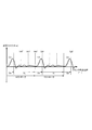
- FIG. 2 is an explanatory diagram schematically showing the relationship between the crank angle position at the time of engine start and the required torque.
- the 4-stroke engine body E has a high load region TH in which the load for rotating the crankshaft 5 is large and a low load region TL in which the load for rotating the crankshaft 5 is smaller than the load in the high load region TH during the four strokes.
- the low load region TL is wider than the high load region TH. More specifically, the low load region TL is wider than the high load region TH. In other words, the rotation angle region corresponding to the low load region TL is wider than the rotation angle region corresponding to the high load region TH.
- the four-stroke engine body E rotates while repeating four steps of an intake stroke, a compression stroke, an expansion stroke, and an exhaust stroke.
- the compression stroke is included in the high load region TH and is not included in the low load region TL.
- the high load region TH is a region that substantially overlaps the compression stroke
- the low load region TL is a region that substantially overlaps the intake stroke, the expansion stroke, and the exhaust stroke.
- each boundary between the high load region TH and the low load region TL does not need to coincide with the boundary of each stroke.
- One cycle of the 4-stroke engine main body E includes an intake stroke, a compression stroke, an expansion stroke, and an exhaust stroke once.
- the engine unit EU includes a three-phase brushless motor SG.
- the three-phase brushless motor SG is a starter motor. More specifically, the three-phase brushless motor SG is a starter generator.
- the three-phase brushless motor SG starts the four-stroke engine body E by rotating the crankshaft 5 forward when the engine is started. Further, the three-phase brushless motor SG is rotated forward by the crankshaft 5 and functions as a generator at least during a period after the start of the four-stroke engine body E. At this time, the three-phase brushless motor SG generates power by rotating in conjunction with the rotation of the crankshaft 5.
- the three-phase brushless motor SG does not always need to function as a generator after starting combustion of the engine. For example, after the combustion of the engine starts, the three-phase brushless motor SG may not function as a generator immediately, and the three-phase brushless motor SG may function as a generator when a predetermined condition is satisfied. Examples of such predetermined conditions include that the engine rotation speed has reached a predetermined speed, and that a predetermined time has elapsed since the start of engine combustion.
- a period during which the three-phase brushless motor SG functions as a generator and a period during which the three-phase brushless motor SG functions as a motor may be included.
- the three-phase brushless motor SG gives resistance to rotation of the crankshaft 5 according to control when the crankshaft 5 is rotating.
- the three-phase brushless motor SG decelerates the rotation of the crankshaft 5 by applying resistance to the rotation of the crankshaft 5.
- the three-phase brushless motor SG is attached to the crankshaft 5 of the 4-stroke engine body E.
- the three-phase brushless motor SG is attached to the crankshaft 5 without a power transmission mechanism (for example, a belt, a chain, a gear, a speed reducer, a speed increaser, etc.).
- the three-phase brushless motor SG only needs to be configured to rotate the crankshaft 5 in the forward direction by the forward rotation of the three-phase brushless motor SG. Therefore, the three-phase brushless motor SG may be attached to the crankshaft 5 via the power transmission mechanism.
- the rotation axis of the three-phase brushless motor SG and the rotation axis of the crankshaft 5 substantially coincide.
- the three-phase brushless motor SG is attached to the crankshaft 5 without using a power transmission mechanism as in the present embodiment.
- the 4-stroke engine body E includes a crankcase 1 (engine case 1), a cylinder 2, a piston 3, a connecting rod 4, and a crankshaft 5.
- the cylinder 2 is provided in a manner protruding from the crankcase 1 in a predetermined direction (for example, obliquely upward).
- the piston 3 is provided in the cylinder 2 so as to be reciprocally movable.
- the crankshaft 5 is rotatably provided in the crankcase 1.
- One end (for example, the upper end) of the connecting rod 4 is connected to the piston 3.
- the other end (for example, the lower end) of the connecting rod 4 is connected to the crankshaft 5.
- a cylinder head 6 is attached to an end portion (for example, an upper end portion) of the cylinder 2.
- crankshaft 5 is supported on the crankcase 1 through a pair of bearings 7 in a rotatable manner.
- One end portion 5 a (for example, right end portion) of the crankshaft 5 protrudes outward from the crankcase 1.
- a three-phase brushless motor SG is attached to one end portion 5 a of the crankshaft 5.
- the other end 5b (for example, the left end) of the crankshaft 5 protrudes outward from the crankcase 1.
- a primary pulley 20 of a continuously variable transmission CVT is attached to the other end portion 5 b of the crankshaft 5.
- the primary pulley 20 has a fixed sheave 21 and a movable sheave 22.
- the fixed sheave 21 is fixed to the distal end portion of the other end portion 5 b of the crankshaft 5 so as to rotate together with the crankshaft 5.
- the movable sheave 22 is splined to the other end 5 b of the crankshaft 5.
- the movable sheave 22 is movable along the axial direction X, and rotates with the crankshaft 5 in such a manner that the distance from the fixed sheave 21 is changed.
- a belt B is hung on the primary pulley 20 and a secondary pulley (not shown). The rotational force of the crankshaft 5 is transmitted to the drive wheels of the motorcycle (see FIG. 9).
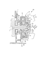
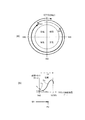
- FIG. 3 is an enlarged cross-sectional view showing the three-phase brushless motor SG in FIG. 1 and the vicinity thereof in an enlarged manner.
- 4 is a cross-sectional view showing a cross section perpendicular to the rotation axis J of the three-phase brushless motor SG shown in FIG.
- the three-phase brushless motor SG has an outer rotor 30 and an inner stator 40.
- the outer rotor 30 has an outer rotor main body 31.
- the outer rotor main body 31 is made of, for example, a ferromagnetic material.
- the outer rotor main body 31 has a bottomed cylindrical shape.
- the outer rotor main body 31 includes a cylindrical boss portion 32, a disk-shaped bottom wall portion 33, and a cylindrical back yoke portion 34.
- the cylindrical boss portion 32 is fixed to the crankshaft 5 while being inserted into the one end portion 5 a of the crankshaft 5.
- the bottom wall portion 33 is fixed to the cylindrical boss portion 32 and has a disk shape that extends in the radial direction Y of the crankshaft 5.
- the back yoke portion 34 has a cylindrical shape that extends in the axial direction X of the crankshaft 5 from the outer peripheral edge of the bottom wall portion 33. The back yoke portion 34 extends in a direction
- the bottom wall portion 33 and the back yoke portion 34 are integrally formed, for example, by press molding a metal plate.
- the bottom wall portion 33 and the back yoke portion 34 may be configured separately. That is, in the outer rotor main body 31, the back yoke portion 34 may be formed integrally with other parts constituting the outer rotor main body 31, and is separate from other parts constituting the outer rotor main body 31. It may be configured on the body. In the case where the back yoke portion 34 and other portions are configured separately, the back yoke portion 34 may be made of a ferromagnetic material, and the other portion may be made of a material other than the ferromagnetic material. .
- a tapered insertion hole 32 a for inserting one end portion 5 a of the crankshaft 5 is formed along the axial direction X of the crankshaft 5.
- the tapered insertion hole 32 a has a taper angle corresponding to the outer peripheral surface of the one end portion 5 a of the crankshaft 5.
- the cylindrical boss portion 32 has a large-diameter portion 32b at the proximal end portion of the cylindrical boss portion 32 (the right portion of the cylindrical boss portion 32 in the drawing).
- the cylindrical boss portion 32 has a flange portion 32c extending outward in the radial direction on the outer peripheral surface of the large diameter portion 32b.
- a large-diameter portion 32b of the cylindrical boss portion 32 is inserted into a hole portion 33a formed in the center portion of the bottom wall portion 33 of the outer rotor main body portion 31. In this state, the flange portion 32c is in contact with the outer peripheral surface (right side surface in the figure) of the bottom wall portion 33.
- the three-phase brushless motor SG is a permanent magnet motor.
- the back yoke portion 34 of the outer rotor main body 31 is provided with a plurality of permanent magnet portions 37 on the inner peripheral surface of the back yoke portion 34.
- Each permanent magnet portion 37 is provided such that the S pole and the N pole are aligned in the radial direction of the three-phase brushless motor SG.
- the plurality of permanent magnet portions 37 are provided so that N poles and S poles are alternately arranged in the circumferential direction of the three-phase brushless motor SG.
- the number of magnetic poles of the outer rotor 30 facing the inner stator 40 is 24.
- the number of magnetic poles of the outer rotor 30 refers to the number of magnetic poles facing the inner stator 40.
- the number of magnetic pole surfaces of the permanent magnet portion 37 facing the tooth portion 43 of the stator core ST corresponds to the number of magnetic poles of the outer rotor 30.
- the magnetic pole surface per magnetic pole included in the outer rotor 30 corresponds to the magnetic pole surface of the permanent magnet portion 37 facing the inner stator 40.
- the magnetic pole surface of the permanent magnet part 37 is covered with a nonmagnetic material (not shown) provided between the permanent magnet part 37 and the inner stator 40. No magnetic material is provided between the permanent magnet portion 37 and the inner stator 40. It does not specifically limit as a nonmagnetic material, For example, a stainless steel material is mentioned.
- the permanent magnet portion 37 is a ferrite magnet.
- conventionally known magnets such as neodymium bond magnets, samarium cobalt magnets and neodymium magnets can be employed as the permanent magnets.
- the shape of the permanent magnet part 37 is not particularly limited.
- the outer rotor 30 may be an embedded magnet type (IPM type) in which the permanent magnet part 37 is embedded in a magnetic material, but the permanent magnet part 37 is exposed from the magnetic material as in the present embodiment.
- a surface magnet type (SPM type) is preferred.
- the outer rotor 30 attached to the crankshaft 5 and attached to rotate together with the crankshaft 5 is a rotating body for increasing the inertia of the crankshaft 5.
- a cooling fan F having a plurality of blade portions Fa is provided on the outer peripheral surface (the right side surface in FIGS. 1 and 3) of the bottom wall portion 33 constituting the outer rotor 30.
- the cooling fan F is fixed to the outer peripheral surface of the bottom wall portion 33 with a fixture (a plurality of bolts Fb).
- the inner stator 40 has a stator core ST and a plurality of stator windings W.
- the stator core ST is formed, for example, by laminating thin silicon steel plates along the axial direction.
- the stator core ST has a hole 41 having an inner diameter larger than the outer diameter of the cylindrical boss portion 32 of the outer rotor 30 at the center of the stator core ST.
- the stator core ST has a plurality of tooth portions 43 that integrally extend outward in the radial direction (see FIG. 4).
- a total of 18 tooth portions 43 are provided at intervals in the circumferential direction.
- the stator core ST has a total of 18 slots SL (see FIG. 4) formed at intervals in the circumferential direction.
- the tooth portions 43 are arranged at substantially equal intervals in the circumferential direction.
- the three-phase brushless motor SG is a three-phase motor.
- the three-phase brushless motor SG includes a plurality of stator windings W corresponding to the three phases.
- a stator winding W is wound around each tooth portion 43.
- the multi-phase stator winding W is provided so as to pass through the slot SL.
- Each of the multi-phase stator windings W belongs to one of the U phase, the V phase, and the W phase.
- the stator windings W are arranged in the order of the U phase, the V phase, and the W phase.
- the stator winding W corresponds to an example of a winding referred to in the present invention.
- the inner stator 40 is formed with a hole 41 in the central portion in the radial direction of the three-phase brushless motor SG.
- the crankshaft 5 and the cylindrical boss portion 32 of the outer rotor 30 are disposed at a distance from the wall surface (inner stator 40) of the hole portion 41.
- the inner stator 40 is attached to the crankcase 1 of the four-stroke engine main body E.
- the end portion (tip surface) of the tooth portion 43 of the inner stator 40 is disposed at a distance from the magnetic pole surface (inner peripheral surface) of the permanent magnet portion 37 constituting the outer rotor 30.
- the outer rotor 30 rotates in conjunction with the rotation of the crankshaft 5.
- the outer rotor 30 rotates integrally with the crankshaft 5. In other words, the rotational speed of the outer rotor 30 is the same as the rotational speed of the crankshaft 5.
- the outer rotor 30 will be further described with reference to FIG.
- the permanent magnet portion 37 is provided outside the inner stator 40 in the radial direction of the three-phase brushless motor SG.
- the back yoke portion 34 is provided outside the permanent magnet portion 37 in the radial direction.
- the permanent magnet portion 37 includes a plurality of magnetic pole surfaces 37 a on the surface facing the inner stator 40.
- the magnetic pole surface 37a is arranged in the circumferential direction of the three-phase brushless motor SG.
- Each of the magnetic pole surfaces 37a is an N pole or an S pole.
- the N pole and the S pole are alternately arranged in the circumferential direction of the three-phase brushless motor SG.
- the magnetic pole surface 37 a of the permanent magnet portion 37 faces the inner stator 40.
- a plurality of magnets are arranged in the circumferential direction of the three-phase brushless motor SG, and each of the plurality of magnets has a posture in which the S pole and the N pole are aligned in the radial direction of the three-phase brushless motor SG.
- a pair of magnetic pole faces 37p is constituted by one S pole and one N pole adjacent in the circumferential direction.
- the number of pairs of magnetic pole faces 37p is 1 ⁇ 2 of the number of magnetic pole faces 37a.
- the outer rotor 30 is provided with 24 magnetic pole surfaces 37a facing the inner stator 40, and the number of pairs 37p of the magnetic pole surfaces of the outer rotor 30 is twelve.
- the three-phase brushless motor SG has more magnetic pole surfaces 37 a than 2/3 of the number of tooth portions 43.
- the three-phase brushless motor SG has the number of magnetic pole surfaces 37 a that is 4/3 or more of the number of tooth portions 43.
- a plurality of detected portions 38 for detecting the rotational position of the outer rotor 30 are provided on the outer surface of the outer rotor 30.
- the plurality of detected parts 38 are detected by a magnetic action.
- the plurality of detected portions 38 are provided on the outer surface of the outer rotor 30 at intervals in the circumferential direction.
- the plurality of detected portions 38 are provided on the outer peripheral surface of the outer rotor 30 at intervals in the circumferential direction.
- the plurality of detected portions 38 are disposed on the outer peripheral surface of the cylindrical back yoke portion 34.
- Each of the plurality of detected portions 38 protrudes outward in the radial direction Y of the three-phase brushless motor SG from the outer peripheral surface of the back yoke portion 34.
- the bottom wall portion 33, the back yoke portion 34, and the detected portion 38 are integrally formed, for example, by press-molding a metal plate such as iron. That is, the detected part 38 is made of a ferromagnetic material. Details of the arrangement of the detected parts 38 will be described later.
- the rotor position detection device 50 is a device that detects the position of the outer rotor 30.
- the rotor position detection device 50 is provided at a position facing the plurality of detected parts 38. That is, the rotor position detection device 50 is disposed at a position where the plurality of detected portions 38 sequentially face the rotor position detection device 50.
- the rotor position detection device 50 faces a path through which the detected portion 38 passes as the outer rotor 30 rotates.
- the rotor position detection device 50 is disposed at a position away from the inner stator 40.
- the rotor position detection device 50 includes the back yoke portion 34 and the permanent magnet portion 37 of the outer rotor 30 between the rotor position detection device 50 and the inner stator 40 and the stator winding W in the radial direction of the crankshaft 5. Is arranged to be located.
- the rotor position detection device 50 is disposed outside the outer rotor 30 in the radial direction of the three-phase brushless motor SG, and faces the outer peripheral surface of the outer rotor 30.
- the rotor position detection device 50 includes a detection winding 51, a detection magnet 52, and a core 53.
- the detection winding 51 functions as a pickup coil that detects the detected portion 38.
- the core 53 is a member extending in the shape of, for example, an iron bar.
- the detection winding 51 magnetically detects the detected portion 38.
- the rotor position detection device 50 starts detecting the rotational position of the outer rotor 30 after the crankshaft 5 starts rotating.
- the rotor position detection device 50 may employ a configuration other than the configuration in which the voltage generated by the electromotive force associated with the passage of the detected portion 38 changes.
- the rotor position detection device 50 may employ a configuration in which the detection winding 51 is always energized and the energization current changes due to the change in inductance accompanying the passage of the detected portion 38.
- the rotor position detection device 50 is not particularly limited, and may include a Hall element or an MR element.
- the engine unit EU (see FIG. 1) of the present embodiment may include a Hall element or an MR element.
- the plurality of detected portions 38 in the present embodiment are provided on the outer surface of the outer rotor 30.
- Each of the plurality of detected portions 38 has the same relative positional relationship with respect to the pair of magnetic pole faces 37p to which each of the detected portions 38 corresponds.
- the rotor position detection device 50 is provided at a position facing the plurality of detected portions 38.
- the rotor position detection device 50 is provided at a position facing each of the plurality of detected portions 38 during rotation of the outer rotor 30.
- the rotor position detection device 50 faces one of the plurality of detected portions 38 instead of the plurality of detected portions 38 at the same time (at a time).
- a predetermined position in the circumferential direction in a pair 37p of magnetic pole faces formed by two magnetic poles (S pole and N pole) adjacent in the circumferential direction is indicated by a one-dot chain line.
- the eleven detected portions 38 that are one less than the number of specified positions are provided in the outer rotor 30.
- the eleven detected parts 38 are respectively provided at eleven of the twelve prescribed positions.
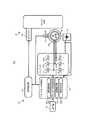
- FIG. 5 is a block diagram showing an electrical basic configuration of the engine unit EU shown in FIG.
- the engine unit EU includes a four-stroke engine body E, a three-phase brushless motor SG, and a control device CT.
- a three-phase brushless motor SG, a spark plug 29, and a battery 14 are connected to the control device CT.
- the control device CT is connected to a plurality of stator windings W, and supplies a current from the battery 14 included in the vehicle to the plurality of stator windings W.
- the control device CT includes a starter motor control unit 62, a combustion control unit 63, and a plurality of switching units 611 to 616.
- the control device CT in the present embodiment has six switching units 611 to 616.
- Switching units 611 to 616 constitute inverter 61.
- the inverter 61 is a three-phase bridge inverter. Switching units 611 to 616 of inverter 61 are provided between battery 14 and three-phase brushless motor SG. Switching units 611 to 616 control the voltage applied from battery 14 to three-phase brushless motor SG.
- the plurality of switching units 611 to 616 are connected to each phase of the plurality of phases of the stator winding W, and switch application / non-application of voltage between the plurality of phases of the stator winding W and the battery 14.
- the plurality of switching units 611 to 616 switches between passing / cutting off current between the plurality of stator windings W and the battery 14. That is, the plurality of switching units 611 to 616 control the current flowing between the battery 14 and the three-phase brushless motor SG. More specifically, when the three-phase brushless motor SG functions as a starter motor, energization and deenergization of each of the plurality of stator windings W are switched by the on / off operations of the switching units 611 to 616.
- the three-phase brushless motor SG functions as a generator
- current passing / cutting between each of the stator windings W and the battery 14 is switched by the on / off operation of the switching units 611 to 616.
- rectification of three-phase AC output from the three-phase brushless motor SG and voltage control are performed.
- Each of the switching units 611 to 616 has a switching element.
- the switching element is, for example, a transistor, and more specifically, an FET (Field Effect Transistor).
- FET Field Effect Transistor
- thyristors and IGBTs Insulated Gate Bipolar Transistors
- the starter motor control unit 62 controls the plurality of switching units 611 to 616.
- the starter motor control unit 62 controls the voltage applied from the battery 14 to the three-phase brushless motor SG by controlling each of the six switching units 611 to 616 corresponding to the three phases.
- the starter motor control unit 62 controls the operation of the three-phase brushless motor SG by controlling the on / off operations of the switching units 611 to 616.
- the starter motor control unit 62 can rotate the three-phase brushless motor SG forward or backward by controlling the on / off operations of the switching units 611 to 616.
- the starter motor control unit 62 includes a drive control unit 621, an on / off operation storage unit 623, an initial operation unit 624, and a resistance applying unit 625.
- the starter motor control unit 62 including the drive control unit 621 and the resistance applying unit 625, and the combustion control unit 63 are realized by a computer (not shown) and control software executed by the computer. However, part or all of the starter motor control unit 62 and the combustion control unit 63 can be realized by a wired logic that is an electronic circuit. In addition, the starter motor control unit 62 and the combustion control unit 63 may be configured as separate devices, for example, at positions separated from each other, or may be configured integrally.
- the drive control unit 621 of the starter motor control unit 62 causes the three-phase brushless motor SG to rotate the crankshaft 5.
- the drive control unit 621 controls the currents flowing between the battery 14 and the three-phase brushless motor SG by controlling the plurality of switching units 611 to 616 provided in the inverter 61. Accordingly, the drive control unit 621 drives the three-phase brushless motor SG.
- the on / off operation storage unit 623 is constituted by a memory, for example.
- the on / off operation storage unit 623 stores data related to the on / off operations of the plurality of switching units 611 to 616. More specifically, the on / off operation storage unit 623 stores a map of information used for the control device CT to control the three-phase brushless motor SG and the four-stroke engine body E, and software in which the information is written. ing.
- the initial operation unit 624 is configured by an electronic circuit. The initial operation unit 624 generates an electric signal for turning on / off the plurality of switching units 611 to 616 when the crankshaft 5 is stopped. Note that the control device CT may operate both the on / off operation storage unit 623 and the initial operation unit 624 in parallel, or may operate one of the on / off operation storage unit 623 and the initial operation unit 624. Good.
- the resistance applying unit 625 performs a process for stopping the rotation of the crankshaft 5 by controlling the rotation of the crankshaft 5 by controlling the three-phase brushless motor SG after the combustion of the 4-stroke engine main body E is stopped.
- the combustion control unit 63 controls the combustion operation of the 4-stroke engine body E by causing the ignition plug 29 to perform an ignition operation.
- the combustion control unit 63 also controls the injection of the fuel injection device to thereby perform the combustion operation of the 4-stroke engine main body E. To control.
- a starter switch 16 for starting the 4-stroke engine main body E is connected to the starter motor control unit 62.
- the starter switch 16 is operated by the driver when the four-stroke engine body E is started.
- the starter motor control unit 62 of the control device CT detects the state of charge of the battery 14 by detecting the voltage of the battery 14.
- the detection of the state of charge of the battery 14 can employ, for example, a configuration for detecting the current flowing through the battery 14 in the state of charge, in addition to the configuration for detecting the voltage of the battery 14.
- the control device CT controls the inverter 61 by the starter motor control unit 62.
- the control device CT controls the three-phase brushless motor SG through the operation of the inverter 61.
- a capacitor (not shown) is provided between the inverter 61 and the battery 14, and the battery 14 and the capacitor constitute a power storage unit.
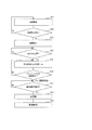
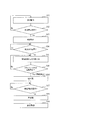
- FIG. 6 is a flowchart for explaining the operation of the engine unit EU shown in FIG.
- the stop operation of the engine unit EU described here is started from the combustion operation state of the engine unit EU (step S11).
- FIG. 7A is a view for explaining the movement of the crankshaft 5 in the engine unit EU shown in FIG.
- FIG. 7B is a diagram schematically showing the relationship between the angular position of the crankshaft 5 and the rotational resistance. The operation of the engine unit EU will be described in order with reference to FIGS.
- the combustion operation state is, for example, an idling state.
- the idling state refers to a state where the vehicle is stopped and the engine is rotating. In the idling state, the engine is in a no-load state and is operating at a minimum rotational speed.
- the combustion state will be described using an example of an idling state.
- the vehicle in which the engine stops while the vehicle is stopped, it is determined that the vehicle has stopped after a predetermined time has elapsed since the vehicle stopped, and the engine stops. In this case, during the period from when the vehicle stops to when it is determined that the vehicle has stopped, the vehicle is in a state where the vehicle is stopped and the engine is stopped, that is, in an idling state.
- step S11 When the engine unit EU is in an idling state, that is, in a combustion operation state (step S11), if no combustion stop instruction is input (step S12: NO), the control device CT continues the combustion operation state. On the other hand, if a combustion stop instruction is input (step S12: YES), the control device CT stops the combustion of the engine (step S13). More specifically, the combustion control unit 63 stops engine combustion.
- the combustion stop instruction may be an internal command generated when the control device CT determines that the vehicle has stopped. Further, the combustion stop instruction may be an external command input by the driver. Even if the combustion of the engine is stopped, the crankshaft 5 continues to rotate temporarily due to inertia. The rotation of the crankshaft 5 is detected by the rotor position detection device 50.
- the control device CT applies resistance to the forward rotation of the crankshaft 5 to the three-phase brushless motor SG to cause the crankshaft 5 to move to the 4-stroke engine.
- the compression stroke in the main body E is stopped (steps S14 to S19).
- the resistance applying unit 625 of the starter motor control unit 62 applies resistance to the forward rotation of the crankshaft 5 to the three-phase brushless motor SG and stops the crankshaft 5 in the compression stroke in the 4-stroke engine body E. .
- the control device CT gives the three-phase brushless motor SG resistance to the forward rotation of the crankshaft 5 based on the position of the crankshaft 5. . Based on the position of the crankshaft 5, the control device CT starts applying resistance to the forward rotation. After the combustion operation of the 4-stroke engine main body E is stopped and before the compression stroke (step S14: YES), the control device CT starts applying resistance to the forward rotation (step S15). The control device CT detects the position of the crankshaft 5 based on a signal from the rotor position detection device 50.
- control device CT may detect the position of the crankshaft 5 by a signal from a device or sensor other than the rotor position detection device 50, for example. Further, the control device CT may detect the rotational speed of the crankshaft 5. In the present embodiment, the control device CT starts applying resistance to the forward rotation of the crankshaft 5 after the crankshaft 5 has passed the compression top dead center and before the compression stroke. In FIG. 7, after the combustion operation of the 4-stroke engine main body E is stopped, the crankshaft 5 passes through a predetermined position P0, whereby resistance is given to the forward rotation of the crankshaft 5 and the compression stroke position P2 is reached. An example of stopping is shown. In this example, position P0 is in the expansion stroke.
- step S15 the control device CT causes the switching units 611 to 616 to short-circuit the terminals of the three-phase stator winding W.
- the control device CT simultaneously turns on the negative side switching units 612, 614, and 616.
- the terminals of the stator winding W are short-circuited.
- all the terminals of the stator winding W are short-circuited. That is, the terminals of the stator winding W are short-circuited for all three phases of the three-phase brushless motor SG.
- the period from when the combustion of the engine is stopped (step S13) to when the terminal of the stator winding W is short-circuited is a period during which the resistance to forward rotation is not applied to the three-phase brushless motor SG.
- FIG. 7B shows the resistance of rotation when the forward rotation of the crankshaft 5 stops at the position P2 in the compression stroke.
- FIG. 7B schematically shows a rotation resistance Ta due to a gas compression reaction force and a rotation resistance Tb due to a short circuit of the terminals of the stator winding W.
- the required torque in FIG. 7B corresponds to the resistance of rotation. Since the resistance due to the short-circuit of the stator winding W is caused by the induced electromotive voltage of the stator winding W, the resistance decreases as the rotational speed of the crankshaft 5 decreases.
- the crankshaft 5 receives a rotation resistance due to the compression reaction force of the gas in the compression stroke.
- the resistance due to the compression reaction force depends on the position of the crankshaft 5 in the compression stroke.
- the resistance Ta due to the compression reaction force increases as the crankshaft rotates forward and approaches the compression top dead center.
- the resistance Ta due to the compression reaction force has a mountain-like characteristic having a peak near the compression top dead center as shown in FIG. Further, the resistance Ta due to the compression reaction force increases as the rotation speed of the crankshaft increases. That is, when the rotational speed of the crankshaft 5 is high, the peak of the resistance Ta increases.
- the control device CT determines stop of rotation of the crankshaft 5 based on a signal output from the rotor position detection device 50 (step S16).
- the rotor position detection device 50 detects a change in electromotive force associated with the passage of the detected portion 38. Therefore, the rotor position detection device 50 of the present embodiment cannot detect the rotation of the crankshaft 5 when the rotation of the crankshaft 5 becomes slow and the change in electromotive force becomes small.
- the crankshaft 5 is rotating at least when the rotation of the crankshaft 5 is detected by the rotor position detection device 50.
- the rotor position detection device 50 is not limited to the example of the present embodiment, and may be configured to detect the rotation of the crankshaft 5 until the rotation of the crankshaft 5 stops, for example.
- step S16 When the rotation of the crankshaft 5 stops (step S16: Yes), the control device CT waits for an input of a start instruction, that is, a restart instruction (step S17).
- the control device CT in the present embodiment continues to short-circuit the terminals of the stator winding W until the next forward rotation of the crankshaft 5 is started.
- the control device CT continues the short circuit of the terminals of the stator winding W after the rotation of the crankshaft 5 stops, so that the stopped state of the crankshaft 5 is stabilized.
- the control device CT can also stop the short circuit of the terminals of the stator winding W when the rotation of the crankshaft 5 stops (step S16: Yes).
- the control device CT controls the plurality of switching units 611 to 616 in response to an input of a start instruction when the combustion operation of the four-stroke engine main body E is stopped and the rotation of the crankshaft is stopped.
- the three-phase brushless motor SG is caused to start normal rotation of the crankshaft 5 (step S18).
- the control device CT starts the forward rotation of the crankshaft 5 from the position where the crankshaft 5 was stopped during the compression stroke.
- the start instruction is input from the starter switch 16 to the control device CT when the starter switch 16 is operated, for example.
- the control device CT executes a start instruction by itself by determining a predetermined engine start condition.
- the achievement of the predetermined engine start condition is included in the input of the start instruction.
- the predetermined engine start condition is, for example, an operation of an accelerator operator (not shown).
- Step S17 the control device CT starts the four-stroke engine main body E by rotating the crankshaft 5 with the three-phase brushless motor SG (Step S18). Specifically, the drive control unit 621 of the starter motor control unit 62 starts the four-stroke engine body E by causing the three-phase brushless motor SG to rotate the crankshaft 5.
- FIG. 7A shows that the crankshaft 5 starts rotating from the position where it has stopped, that is, the position P2 in the compression stroke.
- the variation in the position where the forward rotation of the crankshaft 5 stops is suppressed. That is, the variation in the position at which the crankshaft 5 starts to rotate forward when the four-stroke engine body E is started is suppressed.
- the torque required for the crankshaft 5 to pass over the load peak is affected by the rotational speed accelerated until the crankshaft 5 reaches the load peak. That is, the required torque is affected by the position at which the crankshaft 5 starts to rotate forward.
- the maximum torque required to rotate the crankshaft 5 forward at the start of the 4-stroke engine body E is reduced. Variation is suppressed. Therefore, the output torque required for the three-phase brushless motor for starting the four-stroke engine body can be suppressed.
- the control device CT starts the combustion operation of the 4-stroke engine body E (Step S19). More specifically, the combustion control unit 63 of the control device CT controls the combustion operation of the four-stroke engine main body E by controlling the spark plug 29.
- the combustion control unit 63 also controls the injection of the fuel injection device to thereby perform the combustion operation of the 4-stroke engine main body E. To control.
- the 4-stroke engine main body E is started by starting a combustion operation.
- the three-phase brushless motor SG functions as a generator that generates electric current for charging the battery 14 by rotating in conjunction with the rotation of the crankshaft 5 after starting the four-stroke engine body E. That is, when the 4-stroke engine body E starts combustion, the three-phase brushless motor SG is driven by the 4-stroke engine body E and functions as a generator.
- the control device CT controls the current supplied from the plurality of stator windings W to the battery 14 by turning on / off the plurality of switching units 611 to 616.
- the control device CT turns on / off the plurality of switching units 611 to 616 based on the electrical signal of the detection winding 51 of the rotor position detection device 50.
- Step S17 After the combustion of the 4-stroke engine main body E is stopped and the rotation of the crankshaft 5 is stopped (Yes in Step S16), a restart instruction is input (Yes in Step S17).
- the example in which the control device CT rotates the crankshaft 5 has been described.
- the control device in the present invention is not limited to this. For example, after the rotation of the crankshaft 5 is stopped by applying resistance to the rotation of the crankshaft 5, the control device rotates the crankshaft 5 positively for a predetermined period before inputting the restart instruction. Also good.
- FIG. 8 is a flowchart for explaining the operation of the engine unit EU according to the second embodiment.
- the control device CT provides a resistance to the forward rotation of the crankshaft 5 due to a short circuit of the terminals of the stator winding W, thereby stopping the forward rotation of the crankshaft 5 in the compression stroke.
- the crankshaft 5 is reversely rotated (step S201).
- the control device CT reversely rotates the crankshaft 5 and then rotates it forward (step S18).
- the control device CT controls the switching units 611 to 616 to cause the three-phase brushless motor SG to rotate the crankshaft 5 in the reverse direction.
- the control device CT restarts when the combustion operation of the four-stroke engine main body E is stopped (step S13), and the rotation of the crankshaft 5 is stopped (Yes in step S16).
- the crankshaft 5 is reversely rotated (step S201).
- the drive control unit 621 of the starter motor control unit 62 rotates the crankshaft 5 in the reverse direction (step S201).
- the control device CT rotates the crankshaft 5 in the forward direction (Step S18).
- step S13 after the combustion operation of the four-stroke engine main body E is stopped (step S13), variations in the position where the forward rotation of the crankshaft 5 stops are suppressed. For this reason, when the crankshaft 5 is reversely rotated (step S201), the variation in the position where the reverse rotation of the crankshaft 5 stops is suppressed. That is, in step S18, variations in the position at which the crankshaft 5 starts to rotate forward are suppressed. Since the variation in the position at which the crankshaft 5 starts to rotate forward is suppressed, the maximum torque variation required for the crankshaft 5 to rotate forward is suppressed. Therefore, the torque variation required for the three-phase brushless motor for starting the four-stroke engine body can be suppressed.
- step S201 the example in which the crankshaft 5 is reversely rotated (step S201) when the restart instruction is not input has been described.
- the control device in the present invention is not limited to this.
- the control device according to the present invention may reversely rotate the crankshaft, for example, when a restart instruction is input.
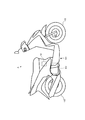
- FIG. 9 is an external view showing a vehicle on which any of the engine units of the first embodiment and the second embodiment is mounted.
- a vehicle A shown in FIG. 9 includes an engine unit EU, a vehicle body 101, wheels 102 and 103, and a battery 14.
- the engine unit EU may be the engine unit EU according to either the first embodiment or the second embodiment.
- the engine unit EU mounted on the vehicle A drives the wheel 103 that is a driving wheel, and rotates the wheel 103 to cause the vehicle A to travel.
- the vehicle A shown in FIG. 9 includes the engine unit EU, it is possible to suppress variations in the position where the rotation of the crankshaft stops after the combustion of the four-stroke engine main body is stopped.
- the vehicle A shown in FIG. 9 is a motorcycle.
- the vehicle of the present invention is not limited to a motorcycle.
- Examples of the vehicle of the present invention include scooter type, moped type, off-road type, and on-road type motorcycles.
- the straddle-type vehicle is not limited to a motorcycle, and may be, for example, an ATV (All-Train Vehicle).
- the vehicle according to the present invention is not limited to a saddle-ride type vehicle, and may be a four-wheel vehicle having a passenger compartment.
- the engine of the present invention is not particularly limited as long as the engine has a high load region and a low load region. That is, a multi-cylinder engine may be used. Examples other than the present embodiment include engines such as an in-line single cylinder, a parallel two-cylinder, an in-line two cylinder, a V-type two cylinder, and a horizontally opposed two-cylinder.
- the number of cylinders of the multi-cylinder engine is not particularly limited, and the multi-cylinder engine may be, for example, a four-cylinder engine.
- some four-cylinder engines do not have a low load region, such as a four-cylinder engine in which the compression stroke of each cylinder occurs at equal intervals (a four-cylinder engine that performs explosion at equal intervals).
- region does not correspond to the engine of this invention.
- the control device CT has a resistance to the forward rotation of the crankshaft 5 before the compression stroke, and the crankshaft 5 is in a position after the compression top dead center in the forward rotation.
- the control device according to the present invention may start giving resistance to the forward rotation of the crankshaft when the crankshaft is in a position before the compression top dead center in the forward rotation.
- the control device according to the present invention may start giving resistance to the forward rotation of the crankshaft before the last cycle before the forward rotation of the crankshaft stops.
- the last cycle is a cycle including an expansion stroke, an exhaust stroke, an intake stroke, and a compression stroke including a compression stroke in which the rotation of the crankshaft stops.
- control device CT applies resistance to the crankshaft 5 due to a short circuit of the terminals of the stator winding W in the compression stroke in which the crankshaft 5 is stopped.
- control device according to the present invention does not necessarily provide resistance due to a short circuit of the terminals of the winding in the compression stroke in which the crankshaft is stopped.
- control device CT short-circuits the terminals of the stator winding W for all three phases of the three-phase brushless motor SG.
- the control device in the present invention may give resistance to rotation of the crankshaft by short-circuiting the terminals for a part of the three phases.
- the control device according to the present invention may short-circuit the terminals of the stator winding corresponding to one of the three phases.
- the control device according to the present invention may short-circuit the terminals of the stator winding corresponding to two phases.
- control device CT provides resistance to the forward rotation of the crankshaft 5 by short-circuiting the terminals of the three-phase stator winding W.
- control device of the present invention may be combined with the provision of resistance not by short-circuiting the terminals of the winding in addition to the provision of resistance by short-circuiting the terminals of the winding.
- the control device first provides resistance to the forward rotation of the crankshaft by controlling the current flowing between the battery and the winding.
- the control device controls the current flowing between the battery and the winding by, for example, vector-controlling the switching unit.
- the control device gives resistance to the forward rotation of the crankshaft 5 by short-circuiting the terminals of the windings.
- the period from the combustion operation stop of the engine to the stop in the compression stroke of the crankshaft is in addition to the period in which the terminals of the plurality of windings are short-circuited to provide resistance to the forward rotation of the crankshaft, Including a period in which resistance to forward rotation is imparted without short-circuiting the circuit.
- engine unit of the present invention may employ the following configuration, for example.
- the period from the stop of the combustion operation of the engine to the stop of the crankshaft in the compression stroke is one or more periods in which the terminals of the plurality of windings are short-circuited to provide resistance to the forward rotation of the crankshaft. In addition, it includes one or more periods that provide resistance to forward rotation without shorting the terminals of the windings.
- the period from the stop of combustion operation of the engine to the stop in the compression stroke of the crankshaft is one or more periods in which the terminals of the plurality of windings are short-circuited to provide resistance to forward rotation of the crankshaft. In addition, it includes one or more periods during which the three-phase brushless motor is not given resistance to forward rotation.
- the period from the stop of the combustion operation of the engine to the stop in the compression stroke of the crankshaft is one or a plurality of periods in which the terminals of the plurality of windings are short-circuited to provide resistance to the forward rotation of the crankshaft.
- it includes one or more periods in which resistance to forward rotation is imparted without short-circuiting the terminals of the winding, and one or more periods in which resistance to forward rotation is not imparted to the three-phase brushless motor.
- the starting point of the period from the stop of the combustion operation of the engine to the stop in the compression stroke of the crankshaft is the short-circuiting of the terminals of the plurality of windings to the forward rotation of the crankshaft. It belongs to the period for applying resistance.
- the starting point of the period from the stop of the combustion operation of the engine to the stop in the compression stroke of the crankshaft belongs to a period in which the resistance to forward rotation is not given to the three-phase brushless motor. Yes.
- the end point of the period from the stop of the combustion operation of the engine to the stop in the compression stroke of the crankshaft is the short-circuiting of the terminals of the plurality of windings to the forward rotation of the crankshaft It is preferable to belong to a period during which resistance is applied, or a period during which resistance to forward rotation is not applied to the three-phase brushless motor. In this case, when the forward rotation of the crankshaft is stopped, it is easy to ensure a balance between the resistance due to the short circuit of the winding terminals and the resistance due to the compression reaction force.
- the period from the stop of the combustion operation of the engine to the stop in the compression stroke of the crankshaft is one or more periods in which the terminals of the plurality of windings are short-circuited to provide resistance to the forward rotation of the crankshaft. In addition, it includes one or more periods that provide resistance to forward rotation without shorting the terminals of the windings.
- the period in which the terminals of the plurality of windings are short-circuited to give resistance to the forward rotation of the crankshaft is the period in which the terminals of only one-phase stator windings are short-circuited, and only the two-phase stator windings At least one of the periods for short-circuiting the terminals may be included.
- the period in which the terminals of the plurality of windings are short-circuited to impart resistance to the forward rotation of the crankshaft is a period in which the terminals of all three-phase stator windings W are short-circuited.
- At least a part of the last cycle before the forward rotation of the crankshaft is stopped 1 provides a resistance to the forward rotation of the crankshaft by short-circuiting a plurality of winding terminals 1 One or more periods are preferred. In this case, when the forward rotation of the crankshaft is stopped, it is easy to ensure a balance between the resistance due to the short circuit of the winding terminals and the resistance due to the compression reaction force.
- At least a part of the compression stroke in which the forward rotation of the crankshaft stops is one or more periods in which the terminals of the plurality of windings are short-circuited to provide resistance to the forward rotation of the crankshaft. ,preferable. In this case, when the forward rotation of the crankshaft is stopped, it is easy to ensure a balance between the resistance due to the short circuit of the winding terminals and the resistance due to the compression reaction force.
- a vehicle CT control device E 4-stroke engine main body EU engine unit SG three-phase brushless motor 5 crankshaft 62 starter motor control unit 63 combustion control unit 61 inverters 611 to 616 switching unit
Abstract
Description
また、このような4ストロークエンジンにおいて、エンジン停止時にクランクシャフトの回転が停止する位置には、ばらつきが生じる。即ち、クランクシャフトの回転が停止する位置は、エンジン停止のたびに異なる。クランクシャフトの回転が停止する位置にばらつきが生じると、例えば、エンジン始動時(再始動時)にクランクシャフトを回転させるために、スタータモータに要求される出力トルクにもばらつきが生じる。しかしながら、ばらつきに対応するためにスタータモータの出力トルクを大きくすると、スタータモータが大型化するため、エンジンユニットの車両への搭載性が低下する。 As an engine provided in a vehicle, a four-stroke engine (for example, a single-cylinder engine) having a high load region where a load for rotating the crankshaft of the engine is large and a low load region where a load for rotating the crankshaft is small during four strokes. ) Such a 4-stroke engine requires a large output torque from the starter motor in order to rotate the crankshaft beyond the high load region when the engine is started.
Further, in such a 4-stroke engine, there is a variation in the position where the rotation of the crankshaft stops when the engine is stopped. In other words, the position at which the rotation of the crankshaft stops changes every time the engine is stopped. If there is a variation in the position at which the rotation of the crankshaft stops, for example, the output torque required for the starter motor also varies because the crankshaft is rotated when the engine is started (restarted). However, if the output torque of the starter motor is increased in order to cope with the variation, the starter motor is increased in size, and the mountability of the engine unit on the vehicle is reduced.
特許文献1に示すようなエンジン始動装置が始動するエンジンは、運転中に燃焼停止の指示があると燃焼を停止する。その後、クランクシャフトの回転が停止する。特許文献1のエンジン始動装置は、エンジン始動操作に応答して、予め設定された位置までエンジンのクランクシャフトを逆回転させるべくスタータモータを駆動した後に停止させる。
特許文献1に示すようなエンジン始動装置では、クランクシャフトを予め設定された位置まで逆回転させ、逆回転を停止することによって、エンジン停止時にクランクシャフトの回転が停止する位置のばらつきの影響の低減を図っている。
An engine started by an engine starter as shown in
In the engine starting device as shown in
(1) 車両に搭載されるエンジンユニットであって、
前記エンジンユニットは、
4ストロークの間に、クランクシャフトを回転させる負荷が大きい高負荷領域と、前記クランクシャフトを回転させる負荷が前記高負荷領域の負荷より小さい低負荷領域とを有する4ストロークエンジン本体と、
三相に応じた複数の巻線を備え、前記車両が備えるバッテリにより駆動され、始動指示の入力に応じて前記クランクシャフトを正回転させて前記4ストロークエンジン本体を始動し、前記4ストロークエンジン本体の始動後、前記クランクシャフトの回転と連動して回転することにより、前記バッテリを充電するための電流を発電するジェネレータとして機能する三相ブラシレスモータと、
前記バッテリと前記三相ブラシレスモータとの間を流れる電流を制御する複数のスイッチング部を備えたインバータと、
前記インバータに備えられた前記複数のスイッチング部を制御することによって、前記バッテリと前記三相ブラシレスモータとの間を流れる電流を制御するスタータモータ制御部と、前記4ストロークエンジン本体の燃焼動作を制御する燃焼制御部とを含む制御装置と
を備え、
前記制御装置は、前記4ストロークエンジン本体の燃焼動作が停止した後、且つ、前記クランクシャフトが正回転している時に、前記複数の巻線の端子を短絡させるよう前記複数のスイッチング部を制御して前記クランクシャフトの正回転への抵抗を付与させることによって、前記クランクシャフトの正回転を前記4ストロークエンジン本体における圧縮行程で停止させる。 The present invention employs the following configuration in order to solve the above-described problems.
(1) An engine unit mounted on a vehicle,
The engine unit is
A four-stroke engine main body having a high load region in which a load for rotating the crankshaft is large during four strokes, and a low load region in which the load for rotating the crankshaft is smaller than the load in the high load region;
The four-stroke engine main body is provided with a plurality of windings corresponding to three phases, is driven by a battery provided in the vehicle, and rotates the crankshaft in accordance with an input of a start instruction to start the four-stroke engine main body. A three-phase brushless motor that functions as a generator that generates electric current for charging the battery by rotating in conjunction with rotation of the crankshaft after starting
An inverter having a plurality of switching units for controlling current flowing between the battery and the three-phase brushless motor;
A starter motor control unit that controls a current flowing between the battery and the three-phase brushless motor by controlling the plurality of switching units provided in the inverter, and a combustion operation of the 4-stroke engine body And a control device including a combustion control unit that
The control device controls the plurality of switching units to short-circuit the terminals of the plurality of windings after the combustion operation of the four-stroke engine main body is stopped and when the crankshaft is rotating forward. By applying resistance to the forward rotation of the crankshaft, the forward rotation of the crankshaft is stopped in the compression stroke in the four-stroke engine body.
(1)のエンジンユニットによれば、巻線の短絡による抵抗によって、クランクシャフトの回転が止まらない程度にクランクシャフトの回転速度を低くし、クランクシャフトが圧縮反力によって跳ね返ることを抑制し、且つ圧縮行程を越えないようにすることができる。(1)のエンジンユニットによれば、複数の巻線の端子の短絡による抵抗の特性と、圧縮反力による抵抗の特性とを利用して、クランクシャフトの正回転が停止する位置のばらつきを抑制することができる。 In the engine unit of (1), the three-phase brushless motor rotates the crankshaft in accordance with the input of the start instruction to start the four-stroke engine main body, and after starting the four-stroke engine main body, interlocks with the rotation of the crankshaft. And rotating to generate a current for charging the battery. The control device controls the plurality of switching portions so that the terminals of the plurality of windings are short-circuited by the control device after the combustion operation of the four-stroke engine main body is stopped and the crankshaft is rotating forward. Provides resistance to forward rotation of the shaft. Therefore, the rotation of the crankshaft is decelerated according to the applied resistance. Since the resistance due to the short circuit of the winding is caused by the induced electromotive voltage of the winding, the resistance is larger as the rotation speed of the crankshaft is larger and is smaller as the rotation speed of the crankshaft is smaller. Therefore, when the rotation speed of the crankshaft is high, the rotation of the crankshaft is rapidly decelerated due to a large resistance. As the rotational speed of the crankshaft decreases, the resistance decreases. On the other hand, since the four-stroke engine body has a high load region and a low load region, the crankshaft is subjected to resistance to rotation due to the compression reaction force in the compression stroke. The resistance due to the compression reaction force increases as the crankshaft rotates forward and approaches the compression top dead center. Further, the resistance due to the compression reaction force is smaller as the rotation speed of the crankshaft is lower.
According to the engine unit of (1), the rotation speed of the crankshaft is lowered to such an extent that the rotation of the crankshaft does not stop due to the resistance due to the short circuit of the winding, the crankshaft is prevented from rebounding by the compression reaction force, and It is possible not to exceed the compression stroke. According to the engine unit of (1), the variation in the position at which the forward rotation of the crankshaft stops is suppressed by utilizing the resistance characteristic due to the short circuit of the terminals of the plurality of windings and the resistance characteristic due to the compression reaction force. can do.
前記制御装置は、前記4ストロークエンジン本体の燃焼動作が停止した後、且つ、前記圧縮行程よりも前に、前記複数の巻線の端子の短絡を開始させるよう前記複数のスイッチング部を制御して前記クランクシャフトの正回転への抵抗を付与させることによって、前記クランクシャフトの正回転を前記4ストロークエンジン本体における圧縮行程で停止させる。 (2) The engine unit of (1),
The control device controls the plurality of switching units to start short-circuiting the terminals of the plurality of windings after the combustion operation of the four-stroke engine main body is stopped and before the compression stroke. By applying resistance to the forward rotation of the crankshaft, the forward rotation of the crankshaft is stopped in the compression stroke in the four-stroke engine body.
前記制御装置は、前記複数の巻線の端子の短絡により前記クランクシャフトの正回転への抵抗が付与されることによって前記クランクシャフトの正回転が前記圧縮行程で停止した後、前記複数のスイッチング部を制御して前記クランクシャフトを正回転させることにより前記4ストロークエンジン本体を始動させる。 (3) The engine unit of (1) or (2),
The control device includes a plurality of switching units after the forward rotation of the crankshaft is stopped in the compression stroke by applying resistance to the forward rotation of the crankshaft by short-circuiting the terminals of the plurality of windings. And the crankshaft is rotated in the forward direction to start the four-stroke engine body.
前記制御装置は、前記複数の巻線の端子の短絡により前記クランクシャフトの正回転への抵抗が付与されることによって前記クランクシャフトの正回転が前記圧縮行程で停止した後、前記複数のスイッチング部を制御して前記クランクシャフトを逆回転させ、前記クランクシャフトを逆回転させた後、正回転させることにより前記4ストロークエンジン本体を始動させる。 (4) The engine unit according to (1) or (2),
The control device includes a plurality of switching units after the forward rotation of the crankshaft is stopped in the compression stroke by applying resistance to the forward rotation of the crankshaft by short-circuiting the terminals of the plurality of windings. The crankshaft is rotated in the reverse direction, the crankshaft is rotated in the reverse direction, and then rotated forward to start the four-stroke engine body.
前記車両は、
(1)から(4)のいずれか1のエンジンユニットを備える。 (5) A vehicle,
The vehicle is
The engine unit according to any one of (1) to (4) is provided.
圧縮反力による抵抗、即ち負荷は、圧縮行程におけるクランクシャフトの位置に対応している。圧縮行程には高負荷領域における負荷の山がある。圧縮反力による負荷は、クランクシャフトが正回転して圧縮上死点に近づくほど大きくなる特性を有する。クランクシャフトは、負荷の山を登るように正回転する。 When a crankshaft in a four-stroke engine body having a high load region and a low load region rotates normally in a compression stroke including the high load region, it receives a resistance to rotation due to a compression reaction force.
The resistance due to the compression reaction force, that is, the load, corresponds to the position of the crankshaft in the compression stroke. There is a load peak in the high load region in the compression stroke. The load due to the compression reaction force has a characteristic that becomes larger as the crankshaft rotates forward and approaches the compression top dead center. The crankshaft rotates forward so as to climb the load peak.
クランクシャフトが圧縮反力で跳ね返されて逆回転し、停止する場合、停止の位置は、圧縮反力に跳ね返される力による。このため、停止の位置のばらつきが大きい。
なお、停止の位置のばらつきが大きいことは、例えばモータによる回転の負荷が付与されない場合、又は負荷が小さい場合に限られず、例えば、4ストロークエンジン本体の燃焼停止後、クランクシャフトの回転がモータの駆動によって補助される場合も同様である。 The resistance due to the compression reaction force, that is, the load is also affected by the rotational speed of the crankshaft. The resistance due to the compression reaction force increases as the rotational speed of the crankshaft increases. For example, a four-stroke engine body stops combustion when there is a combustion stop instruction during operation. After the combustion stops, the crankshaft continues to rotate with inertia. For example, when a load by the motor is not applied to the rotation of the crankshaft or when the load is small, the crankshaft rotates at a high rotation speed in the compression stroke. In this case, the crankshaft receives resistance due to a large compression reaction force. When the crankshaft cannot pass over a large load peak due to the compression reaction force, the crankshaft is bounced back by the compression reaction force, reversely rotates, and stops.
When the crankshaft is rebounded by the compression reaction force and reversely rotates and stops, the stop position depends on the force rebounded by the compression reaction force. For this reason, the variation of the stop position is large.
The fact that the variation in the stop position is large is not limited to, for example, when the rotation load by the motor is not applied or when the load is small. For example, after the combustion of the 4-stroke engine body stops, the rotation of the crankshaft The same applies to the case where it is assisted by driving.
つまり、クランクシャフトが圧縮行程において減速するのに伴い、巻線の短絡による抵抗が徐々に減少し、圧縮反力も圧縮行程の全体に亘って減少する。しかし、クランクシャフトが圧縮行程において回転するのに伴い圧縮反力による抵抗が増大する。
従って、クランクシャフトの圧縮反力による跳ね返りが抑制され、且つクランクシャフトが圧縮行程を乗り越さずに圧縮反力による抵抗の山の途中で停止しやすい。複数の巻線の端子の短絡による抵抗の特性と、圧縮反力による抵抗の特性との組合せによって、クランクシャフトの正回転がある決まった位置又はその近傍に停止し易い。従って、クランクシャフトの正回転が停止する位置のばらつきが抑制される。つまり、複数の巻線の端子の短絡による抵抗の特性と、圧縮反力による抵抗の特性との相乗効果によって、正回転が停止する位置のばらつきが抑制される。 When stopping the forward rotation of the crankshaft in the compression stroke by short-circuiting the terminals of the plurality of windings, the compression reaction force is reduced due to the low rotation speed, so that the rebound of the crankshaft due to the compression reaction force can be suppressed. it can. Further, when the forward rotation of the crankshaft is stopped in the compression stroke by short-circuiting the terminals of the plurality of windings, the resistance characteristic due to the compression reaction force according to the position of the crankshaft in the compression stroke can be effectively used. The resistance due to the compression reaction force is small when the rotation speed of the crankshaft is low. Even in this case, the resistance due to the compression reaction force has a characteristic of increasing as the crankshaft rotates forward and approaches the compression top dead center.
That is, as the crankshaft decelerates during the compression stroke, the resistance due to the short circuit of the winding gradually decreases, and the compression reaction force also decreases throughout the compression stroke. However, as the crankshaft rotates in the compression stroke, the resistance due to the compression reaction force increases.
Therefore, rebounding due to the compression reaction force of the crankshaft is suppressed, and the crankshaft is likely to stop in the middle of the peak of resistance due to the compression reaction force without overcoming the compression stroke. The combination of the resistance characteristic due to short-circuiting of the terminals of the plurality of windings and the resistance characteristic due to compression reaction force makes it easy to stop the crankshaft at a certain position or in the vicinity thereof. Therefore, variation in the position where the forward rotation of the crankshaft stops is suppressed. That is, the variation in the position where the forward rotation stops is suppressed by the synergistic effect of the resistance characteristic due to the short circuit of the terminals of the plurality of windings and the resistance characteristic due to the compression reaction force.
図1は、本発明の第一実施形態に係るエンジンユニットEUの概略構成を模式的に示す部分断面図である。なお、本実施形態におけるエンジンユニットEUは、車両用4ストロークエンジンユニットである。 [Engine unit]
FIG. 1 is a partial cross-sectional view schematically showing a schematic configuration of an engine unit EU according to the first embodiment of the present invention. The engine unit EU in the present embodiment is a vehicle four-stroke engine unit.
4ストロークエンジン本体Eの1サイクルには、吸気行程、圧縮行程、膨張行程、及び排気行程が1回ずつ含まれる。 The 4-stroke engine body E has a high load region TH in which the load for rotating the
One cycle of the 4-stroke engine main body E includes an intake stroke, a compression stroke, an expansion stroke, and an exhaust stroke once.
また、三相ブラシレスモータSGは、クランクシャフト5が回転しているとき、制御に応じてクランクシャフト5の回転に抵抗を付与する。三相ブラシレスモータSGは、クランクシャフト5の回転に抵抗を付与することによって、クランクシャフト5の回転を減速させる。 As shown in FIG. 1, the engine unit EU includes a three-phase brushless motor SG. The three-phase brushless motor SG is a starter motor. More specifically, the three-phase brushless motor SG is a starter generator. The three-phase brushless motor SG starts the four-stroke engine body E by rotating the
The three-phase brushless motor SG gives resistance to rotation of the
エンジンユニットEUは、4ストロークエンジン本体E、三相ブラシレスモータSG、及び制御装置CTを備えている。制御装置CTには、三相ブラシレスモータSG、点火プラグ29、及びバッテリ14が接続されている。 FIG. 5 is a block diagram showing an electrical basic configuration of the engine unit EU shown in FIG.
The engine unit EU includes a four-stroke engine body E, a three-phase brushless motor SG, and a control device CT. A three-phase brushless motor SG, a
駆動制御部621、及び抵抗付与部625を含むスタータモータ制御部62と、燃焼制御部63とは、図示しないコンピュータとコンピュータで実行される制御ソフトウェアとによって実現される。ただし、スタータモータ制御部62と、燃焼制御部63との一部又は全部は、電子回路であるワイヤードロジックによって実現することも可能である。また、スタータモータ制御部62及び燃焼制御部63は、例えば互いに別の装置として互いに離れた位置に構成されてもよく、また、一体に構成されるものであってもよい。 The starter
The starter
図6は、図1に示すエンジンユニットEUの動作を説明するフローチャートである。
ここで説明するエンジンユニットEUの停止動作は、エンジンユニットEUの燃焼動作状態から開始される(ステップS11)。
また、図7(a)は、図1に示すエンジンユニットEUにおける、クランクシャフト5の動きを説明する図である。図7(b)は、クランクシャフト5の角度位置と回転の抵抗との関係を模式的に示す図である。
図6及び図7を参照しながら、エンジンユニットEUの動作を順に説明する。 [Engine unit operation]
FIG. 6 is a flowchart for explaining the operation of the engine unit EU shown in FIG.
The stop operation of the engine unit EU described here is started from the combustion operation state of the engine unit EU (step S11).
FIG. 7A is a view for explaining the movement of the
The operation of the engine unit EU will be described in order with reference to FIGS.
より詳細には、4ストロークエンジン本体Eの燃焼動作が停止した後、制御装置CTは、クランクシャフト5の位置に基づいて、三相ブラシレスモータSGにクランクシャフト5の正回転への抵抗を付与させる。制御装置CTは、クランクシャフト5の位置に基づいて、正回転への抵抗の付与を開始する。制御装置CTは、4ストロークエンジン本体Eの燃焼動作が停止した後、且つ、圧縮行程よりも前に(ステップS14:YES)、正回転への抵抗の付与を開始する(ステップS15)。
制御装置CTは、ロータ位置検出装置50からの信号によってクランクシャフト5の位置を検出する。ただし、制御装置CTは、例えば、ロータ位置検出装置50以外の装置又はセンサからの信号によって、クランクシャフト5の位置を検出してもよい。また、制御装置CTは、クランクシャフト5の回転速度を検出してもよい。
本実施形態において、制御装置CTは、クランクシャフト5が、圧縮上死点を通過した後、且つ、圧縮行程よりも前に、クランクシャフト5の正回転への抵抗の付与を開始する。
図7には、4ストロークエンジン本体Eの燃焼動作が停止した後、クランクシャフト5が予め定めた位置P0を通過したことによって、クランクシャフト5の正回転へ抵抗が付与され、圧縮行程の位置P2に停止する例が示されている。この例において、位置P0は、膨張行程内にある。 After the combustion operation of the 4-stroke engine main body E is stopped (after step S13), the control device CT applies resistance to the forward rotation of the
More specifically, after the combustion operation of the four-stroke engine main body E is stopped, the control device CT gives the three-phase brushless motor SG resistance to the forward rotation of the
The control device CT detects the position of the
In the present embodiment, the control device CT starts applying resistance to the forward rotation of the
In FIG. 7, after the combustion operation of the 4-stroke engine main body E is stopped, the
なお、エンジンの燃焼停止(ステップS13)から、ステータ巻線Wの端子が短絡するまでの期間は、三相ブラシレスモータSGに正回転への抵抗を付与させない期間である。 In step S15 described above, the control device CT causes the switching
Note that the period from when the combustion of the engine is stopped (step S13) to when the terminal of the stator winding W is short-circuited is a period during which the resistance to forward rotation is not applied to the three-phase brushless motor SG.
ステータ巻線Wの端子の短絡による抵抗はステータ巻線Wの誘導起電圧に起因するため、抵抗はクランクシャフト5の回転速度が大きいほど大きく、クランクシャフト5の回転速度が小さいほど小さい。従って、クランクシャフト5の回転速度が大きい時には、大きな抵抗によってクランクシャフト5の回転が急減速する。つまり、ステータ巻線Wの端子の短絡によるブレーキは、クランクシャフト5の回転速度が高いほど効く。クランクシャフト5の回転速度が減少するのに伴い、抵抗は小さくなる。つまり、ステータ巻線Wの端子の短絡によるブレーキは、クランクシャフト5の回転速度が低いほど効かない。
複数のステータ巻線Wの端子を短絡させることによってクランクシャフト5の正回転を圧縮行程で停止させることによって、圧縮行程での圧縮反力による抵抗を効果的に利用できる。 When the terminal of the stator winding W is short-circuited, a current due to an induced electromotive voltage generated in the stator winding W flows through the stator winding W. The current flowing through the stator winding W causes a resistance to rotation in the three-phase brushless motor SG. The three-phase brushless motor SG gives resistance to the rotation of the
Since the resistance due to the short circuit of the terminals of the stator winding W is due to the induced electromotive voltage of the stator winding W, the resistance increases as the rotation speed of the
By stopping the rotation of the
ステータ巻線Wの短絡による抵抗はステータ巻線Wの誘導起電圧に起因するため、クランクシャフト5の回転速度が減少するのに伴い、抵抗は小さくなる。回転速度が低いとステータ巻線Wの端子の短絡による抵抗は小さいので、クランクシャフト5は、回転が止まらない程度に低い回転速度で回転し易い。
この一方で、クランクシャフト5は、圧縮行程において、気体の圧縮反力による回転の抵抗を受ける。圧縮反力による抵抗は、圧縮行程におけるクランクシャフト5の位置に応じている。圧縮反力による抵抗Taは、クランクシャフトが正回転して圧縮上死点に近づくほど大きくなる。圧縮反力による抵抗Taは、図7(b)に示すように圧縮上死点近傍にピークを有する山のような特性を有する。また、圧縮反力による抵抗Taは、クランクシャフトの回転速度が高いほど大きい。つまり、クランクシャフト5の回転速度が高いと、抵抗Taの山は高くなる。 FIG. 7B shows the resistance of rotation when the forward rotation of the
Since the resistance due to the short-circuit of the stator winding W is caused by the induced electromotive voltage of the stator winding W, the resistance decreases as the rotational speed of the
On the other hand, the
クランクシャフト5が圧縮行程において減速するのに伴い、ステータ巻線Wの短絡による回転の抵抗Tbが徐々に小さくなる一方で、クランクシャフト5が圧縮行程において正回転するのに伴い圧縮反力による抵抗Taが大きくなる。ステータ巻線Wの短絡による抵抗Tbの減少と、圧縮反力による抵抗Taの増大とのバランスによって、クランクシャフト5の正回転が停止する位置を安定化できる。従って、クランクシャフト5の正回転が停止する位置のばらつきを抑制することができる。 Further, in the compression stroke, by imparting resistance to the
As the
始動指示は、例えば、スタータスイッチ16が操作された場合に、スタータスイッチ16から制御装置CTに入力される。また、エンジンユニットEUがアイドリングストップ機能を有する場合、制御装置CTは、予め定めたエンジン始動条件を判別することによって、自ら始動の指示を実行する。予め定めたエンジン始動条件の達成は、始動指示の入力に含まれる。予め定めたエンジン始動条件は、例えば、図示しないアクセル操作子の操作である。 The control device CT controls the plurality of switching
The start instruction is input from the
図7(a)には、クランクシャフト5が、停止していた位置、即ち圧縮行程内の位置P2から、回転を開始することが示されている。 When the start instruction is input (Yes in Step S17), the control device CT starts the four-stroke engine main body E by rotating the
FIG. 7A shows that the
続いて、本発明の第二実施形態について説明する。以下の第二実施形態の説明にあたっては、第一実施形態における各要素と対応する要素には同一の符号を付し、上述した第一実施形態との相違点を主に説明する。 [Second Embodiment]
Next, a second embodiment of the present invention will be described. In the following description of the second embodiment, elements corresponding to those in the first embodiment are denoted by the same reference numerals, and differences from the first embodiment described above will be mainly described.
本実施形態のエンジンユニットEUにおいて、制御装置CTは、ステータ巻線Wの端子の短絡によりクランクシャフト5の正回転への抵抗が付与されることによってクランクシャフト5の正回転が圧縮行程で停止した後、クランクシャフト5を逆回転(ステップS201)させる。制御装置CTは、クランクシャフト5を逆回転させた後、正回転させる(ステップS18)。制御装置CTは、複数のスイッチング部611~616を制御して、三相ブラシレスモータSGにクランクシャフト5を逆回転させる。
より詳細には、制御装置CTは、4ストロークエンジン本体Eの燃焼動作が停止し(ステップS13)、且つ、クランクシャフト5の回転が停止している時(ステップS16でYes)、且つ、再始動の指示が入力されていない時に、クランクシャフト5を逆回転(ステップS201)させる。詳細には、スタータモータ制御部62の駆動制御部621が、クランクシャフト5を逆回転(ステップS201)させる。制御装置CTは、再始動の指示が入力されると(ステップS17でYes)、クランクシャフト5を正回転させる(ステップS18)。 FIG. 8 is a flowchart for explaining the operation of the engine unit EU according to the second embodiment.
In the engine unit EU of the present embodiment, the control device CT provides a resistance to the forward rotation of the
More specifically, the control device CT restarts when the combustion operation of the four-stroke engine main body E is stopped (step S13), and the rotation of the
クランクシャフト5が正回転を開始する位置のばらつきが抑制されているので、クランクシャフト5が正回転するために要求される最大のトルクのばらつきが抑制される。従って、4ストロークエンジン本体を始動させるため三相ブラシレスモータに要求されるトルクのばらつきが抑制できる。 In the engine unit EU of the present embodiment, after the combustion operation of the four-stroke engine main body E is stopped (step S13), variations in the position where the forward rotation of the
Since the variation in the position at which the
図9は、第一実施形態及び第二実施形態のいずれかのエンジンユニットが搭載される車両を示す外観図である。 [Motorcycle]
FIG. 9 is an external view showing a vehicle on which any of the engine units of the first embodiment and the second embodiment is mounted.
CT 制御装置
E 4ストロークエンジン本体
EU エンジンユニット
SG 三相ブラシレスモータ
5 クランクシャフト
62 スタータモータ制御部
63 燃焼制御部
61 インバータ
611~616 スイッチング部 A vehicle CT control device E 4-stroke engine main body EU engine unit SG three-
Claims (5)
- 車両に搭載されるエンジンユニットであって、
前記エンジンユニットは、
4ストロークの間に、クランクシャフトを回転させる負荷が大きい高負荷領域と、前記クランクシャフトを回転させる負荷が前記高負荷領域の負荷より小さい低負荷領域とを有する4ストロークエンジン本体と、
三相に応じた複数の巻線を備え、前記車両が備えるバッテリにより駆動され、始動指示の入力に応じて前記クランクシャフトを正回転させて前記4ストロークエンジン本体を始動し、前記4ストロークエンジン本体の始動後、前記クランクシャフトの回転と連動して回転することにより、前記バッテリを充電するための電流を発電するジェネレータとして機能する三相ブラシレスモータと、
前記バッテリと前記三相ブラシレスモータとの間を流れる電流を制御する複数のスイッチング部を備えたインバータと、
前記インバータに備えられた前記複数のスイッチング部を制御することによって、前記バッテリと前記三相ブラシレスモータとの間を流れる電流を制御するスタータモータ制御部と、前記4ストロークエンジン本体の燃焼動作を制御する燃焼制御部とを含む制御装置と
を備え、
前記制御装置は、前記4ストロークエンジン本体の燃焼動作が停止した後、且つ、前記クランクシャフトが正回転している時に、前記複数の巻線の端子を短絡させるよう前記複数のスイッチング部を制御して前記クランクシャフトの正回転への抵抗を付与させることによって、前記クランクシャフトの正回転を前記4ストロークエンジン本体における圧縮行程で停止させる。 An engine unit mounted on a vehicle,
The engine unit is
A four-stroke engine main body having a high load region in which a load for rotating the crankshaft is large during four strokes, and a low load region in which the load for rotating the crankshaft is smaller than the load in the high load region;
The four-stroke engine main body is provided with a plurality of windings corresponding to three phases, is driven by a battery provided in the vehicle, and rotates the crankshaft in accordance with an input of a start instruction to start the four-stroke engine main body. A three-phase brushless motor that functions as a generator that generates electric current for charging the battery by rotating in conjunction with rotation of the crankshaft after starting
An inverter having a plurality of switching units for controlling current flowing between the battery and the three-phase brushless motor;
A starter motor control unit that controls a current flowing between the battery and the three-phase brushless motor by controlling the plurality of switching units provided in the inverter, and a combustion operation of the 4-stroke engine body And a control device including a combustion control unit that
The control device controls the plurality of switching units to short-circuit the terminals of the plurality of windings after the combustion operation of the four-stroke engine main body is stopped and when the crankshaft is rotating forward. By applying resistance to the forward rotation of the crankshaft, the forward rotation of the crankshaft is stopped in the compression stroke in the four-stroke engine body. - 請求項1に記載のエンジンユニットであって、
前記制御装置は、前記4ストロークエンジン本体の燃焼動作が停止した後、且つ、前記圧縮行程よりも前に、前記複数の巻線の端子の短絡を開始させるよう前記複数のスイッチング部を制御して前記クランクシャフトの正回転への抵抗を付与させることによって、前記クランクシャフトの正回転を前記4ストロークエンジン本体における圧縮行程で停止させる。 The engine unit according to claim 1,
The control device controls the plurality of switching units to start short-circuiting the terminals of the plurality of windings after the combustion operation of the four-stroke engine main body is stopped and before the compression stroke. By applying resistance to the forward rotation of the crankshaft, the forward rotation of the crankshaft is stopped in the compression stroke in the four-stroke engine body. - 請求項1又は2に記載のエンジンユニットであって、
前記制御装置は、前記複数の巻線の端子の短絡により前記クランクシャフトの正回転への抵抗が付与されることによって前記クランクシャフトの正回転が前記圧縮行程で停止した後、前記複数のスイッチング部を制御して前記クランクシャフトを正回転させることにより前記4ストロークエンジン本体を始動させる。 The engine unit according to claim 1 or 2,
The control device includes a plurality of switching units after the forward rotation of the crankshaft is stopped in the compression stroke by applying resistance to the forward rotation of the crankshaft by short-circuiting the terminals of the plurality of windings. And the crankshaft is rotated in the forward direction to start the four-stroke engine body. - 請求項1又は2に記載のエンジンユニットであって、
前記制御装置は、前記複数の巻線の端子の短絡により前記クランクシャフトの正回転への抵抗が付与されることによって前記クランクシャフトの正回転が前記圧縮行程で停止した後、前記複数のスイッチング部を制御して前記クランクシャフトを逆回転させ、前記クランクシャフトを逆回転させた後、正回転させることにより前記4ストロークエンジン本体を始動させる。 The engine unit according to claim 1 or 2,
The control device includes a plurality of switching units after the forward rotation of the crankshaft is stopped in the compression stroke by applying resistance to the forward rotation of the crankshaft by short-circuiting the terminals of the plurality of windings. The crankshaft is rotated in the reverse direction, the crankshaft is rotated in the reverse direction, and then rotated forward to start the four-stroke engine body. - 車両であって、
前記車両は、
請求項1から4のいずれか1に記載のエンジンユニットを備える。 A vehicle,
The vehicle is
An engine unit according to any one of claims 1 to 4 is provided.
Priority Applications (5)
| Application Number | Priority Date | Filing Date | Title |
|---|---|---|---|
| CN201480070284.XA CN105829704B (en) | 2013-12-20 | 2014-12-18 | Engine unit and vehicle |
| EP14872412.3A EP3064763A4 (en) | 2013-12-20 | 2014-12-18 | Engine unit and vehicle |
| EP20171875.6A EP3705713A1 (en) | 2013-12-20 | 2014-12-18 | Engine unit and vehicle |
| AP2016009310A AP2016009310A0 (en) | 2013-12-20 | 2014-12-18 | Engine unit and vehicle |
| TW103144932A TWI553220B (en) | 2013-12-20 | 2014-12-19 | Engine unit and vehicle |
Applications Claiming Priority (4)
| Application Number | Priority Date | Filing Date | Title |
|---|---|---|---|
| JP2013263309A JP2017036666A (en) | 2013-12-20 | 2013-12-20 | Engine unit |
| JP2013263308A JP2017036665A (en) | 2013-12-20 | 2013-12-20 | Engine unit |
| JP2013-263309 | 2013-12-20 | ||
| JP2013-263308 | 2013-12-20 |
Publications (1)
| Publication Number | Publication Date |
|---|---|
| WO2015093577A1 true WO2015093577A1 (en) | 2015-06-25 |
Family
ID=53402918
Family Applications (2)
| Application Number | Title | Priority Date | Filing Date |
|---|---|---|---|
| PCT/JP2014/083594 WO2015093577A1 (en) | 2013-12-20 | 2014-12-18 | Engine unit and vehicle |
| PCT/JP2014/083593 WO2015093576A1 (en) | 2013-12-20 | 2014-12-18 | Engine unit and vehicle |
Family Applications After (1)
| Application Number | Title | Priority Date | Filing Date |
|---|---|---|---|
| PCT/JP2014/083593 WO2015093576A1 (en) | 2013-12-20 | 2014-12-18 | Engine unit and vehicle |
Country Status (5)
| Country | Link |
|---|---|
| EP (3) | EP3064763A4 (en) |
| CN (3) | CN105829704B (en) |
| AP (2) | AP2016009310A0 (en) |
| TW (2) | TWI551776B (en) |
| WO (2) | WO2015093577A1 (en) |
Cited By (2)
| Publication number | Priority date | Publication date | Assignee | Title |
|---|---|---|---|---|
| WO2017126463A1 (en) * | 2016-01-20 | 2017-07-27 | ヤマハ発動機株式会社 | Vehicle |
| WO2017126165A1 (en) * | 2016-01-20 | 2017-07-27 | ヤマハ発動機株式会社 | Engine-equipped vehicle |
Families Citing this family (9)
| Publication number | Priority date | Publication date | Assignee | Title |
|---|---|---|---|---|
| ITUB20152786A1 (en) * | 2015-08-03 | 2017-02-03 | Piaggio & C Spa | PROCEDURE FOR MANAGING THE RE-STARTING OF AN INTERNAL COMBUSTION ENGINE IN A START AND STOP SYSTEM |
| TWI617736B (en) * | 2015-10-29 | 2018-03-11 | 三陽工業股份有限公司 | Method for controlling and protecting power generation after switching off power of a vehicle |
| JP2018053775A (en) * | 2016-09-28 | 2018-04-05 | ヤマハ発動機株式会社 | Saddle riding type vehicle |
| JP2018053772A (en) * | 2016-09-28 | 2018-04-05 | ヤマハ発動機株式会社 | Engine unit and saddle-riding type vehicle |
| US10605217B2 (en) * | 2017-03-07 | 2020-03-31 | GM Global Technology Operations LLC | Vehicle engine starter control systems and methods |
| WO2018212093A1 (en) | 2017-05-15 | 2018-11-22 | ヤマハ発動機株式会社 | Engine unit |
| WO2019017087A1 (en) * | 2017-07-18 | 2019-01-24 | ヤマハ発動機株式会社 | Vehicle |
| JP2020152121A (en) * | 2017-07-18 | 2020-09-24 | ヤマハ発動機株式会社 | Vehicle |
| CN112253350B (en) * | 2020-09-16 | 2022-02-18 | 清华大学 | Engine starting method and starting system using the same |
Citations (4)
| Publication number | Priority date | Publication date | Assignee | Title |
|---|---|---|---|---|
| JP2001193540A (en) * | 2000-01-14 | 2001-07-17 | Kokusan Denki Co Ltd | Stop position controlling method and device for internal combustion engine |
| JP2003343404A (en) | 2002-05-22 | 2003-12-03 | Honda Motor Co Ltd | Engine starting device |
| JP2004028010A (en) * | 2002-06-27 | 2004-01-29 | Honda Motor Co Ltd | Engine starter |
| JP2004068632A (en) * | 2002-08-02 | 2004-03-04 | Toyota Motor Corp | Control device of internal combustion engine |
Family Cites Families (16)
| Publication number | Priority date | Publication date | Assignee | Title |
|---|---|---|---|---|
| US4949021A (en) * | 1988-11-14 | 1990-08-14 | Sunstrand Corporation | Variable speed constant frequency start system with selectable input power limiting |
| JP2552912B2 (en) * | 1989-02-15 | 1996-11-13 | 日野自動車工業株式会社 | Retarder |
| CN1279279C (en) * | 1999-11-24 | 2006-10-11 | 株式会社美姿把 | Starter, start control device, and crank angle detector of internal combustion engine |
| FR2806757B1 (en) * | 2000-03-21 | 2002-06-21 | Peugeot Citroen Automobiles Sa | METHOD AND DEVICE FOR POSITIONING A HEAT ENGINE, IN A STOP POSITION FOR EASIER STARTING |
| JP2004036428A (en) * | 2002-07-01 | 2004-02-05 | Toyota Motor Corp | Control device for internal combustion engine |
| JP4169193B2 (en) * | 2003-02-21 | 2008-10-22 | 本田技研工業株式会社 | Engine driven work machine |
| JP2005163718A (en) * | 2003-12-04 | 2005-06-23 | Nissan Motor Co Ltd | Controller for hybrid vehicle |
| JP4315287B2 (en) * | 2004-03-08 | 2009-08-19 | 本田技研工業株式会社 | Engine start control device |
| JP4293138B2 (en) * | 2005-02-03 | 2009-07-08 | トヨタ自動車株式会社 | Control device for internal combustion engine and automobile equipped with the control device |
| JP4254852B2 (en) * | 2006-12-06 | 2009-04-15 | トヨタ自動車株式会社 | Vehicle and control method thereof |
| JP4978429B2 (en) * | 2007-11-01 | 2012-07-18 | アイシン・エィ・ダブリュ株式会社 | Electric motor control device, electric vehicle and hybrid electric vehicle |
| US8020652B2 (en) * | 2007-12-04 | 2011-09-20 | Ford Global Technologies, Llc | Generator power-based cold start strategy |
| JP4506889B2 (en) * | 2008-10-23 | 2010-07-21 | トヨタ自動車株式会社 | AC motor control apparatus and control method |
| US8573173B2 (en) * | 2009-11-17 | 2013-11-05 | Freescale Semiconductor, Inc. | Four stroke single cylinder combustion engine starting system |
| WO2012036184A1 (en) * | 2010-09-16 | 2012-03-22 | 新電元工業株式会社 | Drive controller, drive control system, and drive control method |
| CN103519320A (en) * | 2013-10-16 | 2014-01-22 | 青岛田瑞牧业科技有限公司 | Feed preservative |
-
2014
- 2014-12-18 AP AP2016009310A patent/AP2016009310A0/en unknown
- 2014-12-18 WO PCT/JP2014/083594 patent/WO2015093577A1/en active Application Filing
- 2014-12-18 CN CN201480070284.XA patent/CN105829704B/en not_active Expired - Fee Related
- 2014-12-18 EP EP14872412.3A patent/EP3064763A4/en not_active Withdrawn
- 2014-12-18 WO PCT/JP2014/083593 patent/WO2015093576A1/en active Application Filing
- 2014-12-18 EP EP20171875.6A patent/EP3705713A1/en not_active Ceased
- 2014-12-18 EP EP14870978.5A patent/EP3064762B1/en active Active
- 2014-12-18 CN CN201710617344.0A patent/CN107795422B/en not_active Expired - Fee Related
- 2014-12-18 CN CN201480070031.2A patent/CN105849404B/en not_active Expired - Fee Related
- 2014-12-18 AP AP2016009307A patent/AP2016009307A0/en unknown
- 2014-12-19 TW TW103144930A patent/TWI551776B/en not_active IP Right Cessation
- 2014-12-19 TW TW103144932A patent/TWI553220B/en not_active IP Right Cessation
Patent Citations (4)
| Publication number | Priority date | Publication date | Assignee | Title |
|---|---|---|---|---|
| JP2001193540A (en) * | 2000-01-14 | 2001-07-17 | Kokusan Denki Co Ltd | Stop position controlling method and device for internal combustion engine |
| JP2003343404A (en) | 2002-05-22 | 2003-12-03 | Honda Motor Co Ltd | Engine starting device |
| JP2004028010A (en) * | 2002-06-27 | 2004-01-29 | Honda Motor Co Ltd | Engine starter |
| JP2004068632A (en) * | 2002-08-02 | 2004-03-04 | Toyota Motor Corp | Control device of internal combustion engine |
Non-Patent Citations (1)
| Title |
|---|
| See also references of EP3064763A4 |
Cited By (5)
| Publication number | Priority date | Publication date | Assignee | Title |
|---|---|---|---|---|
| WO2017126463A1 (en) * | 2016-01-20 | 2017-07-27 | ヤマハ発動機株式会社 | Vehicle |
| WO2017126165A1 (en) * | 2016-01-20 | 2017-07-27 | ヤマハ発動機株式会社 | Engine-equipped vehicle |
| TWI624585B (en) * | 2016-01-20 | 2018-05-21 | Yamaha Motor Co Ltd | Vehicle |
| EP3404236A4 (en) * | 2016-01-20 | 2018-12-26 | Yamaha Hatsudoki Kabushiki Kaisha | Vehicle |
| EP3407482A4 (en) * | 2016-01-20 | 2019-08-21 | Yamaha Hatsudoki Kabushiki Kaisha | Engine-equipped vehicle |
Also Published As
| Publication number | Publication date |
|---|---|
| EP3064762B1 (en) | 2021-07-07 |
| AP2016009310A0 (en) | 2016-07-31 |
| CN105849404B (en) | 2018-02-23 |
| EP3705713A1 (en) | 2020-09-09 |
| WO2015093576A1 (en) | 2015-06-25 |
| CN105829704A (en) | 2016-08-03 |
| EP3064763A1 (en) | 2016-09-07 |
| CN107795422A (en) | 2018-03-13 |
| CN107795422B (en) | 2019-05-21 |
| EP3064762A1 (en) | 2016-09-07 |
| TWI551776B (en) | 2016-10-01 |
| TW201527640A (en) | 2015-07-16 |
| CN105849404A (en) | 2016-08-10 |
| EP3064762A4 (en) | 2017-03-15 |
| AP2016009307A0 (en) | 2016-07-31 |
| TW201533313A (en) | 2015-09-01 |
| EP3064763A4 (en) | 2017-03-08 |
| TWI553220B (en) | 2016-10-11 |
| CN105829704B (en) | 2021-05-04 |
Similar Documents
| Publication | Publication Date | Title |
|---|---|---|
| WO2015093577A1 (en) | Engine unit and vehicle | |
| WO2015093574A1 (en) | Engine unit and vehicle | |
| WO2015093575A1 (en) | Engine unit and vehicle | |
| TWI546447B (en) | Four-stroke engine unit for use in vehicle and vehicle | |
| EP3315764A2 (en) | Engine unit and straddled vehicle | |
| JP2017036666A (en) | Engine unit | |
| JP2019054559A (en) | Vehicle | |
| JP2015117677A (en) | Engine unit and vehicle | |
| JP2017036665A (en) | Engine unit | |
| JP2017129065A (en) | Vehicle | |
| JP2018053773A (en) | Saddle-riding type vehicle | |
| JP2018053774A (en) | Vehicle | |
| OA17779A (en) | Engine unit and vehicle. | |
| TW202129145A (en) | Straddled vehicle | |
| JP2022181657A (en) | Engine starter | |
| JP2021179203A (en) | Engine start control device | |
| OA17770A (en) | Engine unit and vehicle | |
| OA17801A (en) | Engine unit and vehicle | |
| OA17778A (en) | Engine unit and vehicle | |
| OA17492A (en) | Four stroke engine unit for use in vehicle and vehicle. |
Legal Events
| Date | Code | Title | Description |
|---|---|---|---|
| 121 | Ep: the epo has been informed by wipo that ep was designated in this application |
Ref document number: 14872412 Country of ref document: EP Kind code of ref document: A1 |
|
| REEP | Request for entry into the european phase |
Ref document number: 2014872412 Country of ref document: EP |
|
| WWE | Wipo information: entry into national phase |
Ref document number: 2014872412 Country of ref document: EP |
|
| NENP | Non-entry into the national phase |
Ref country code: DE |
|
| WWE | Wipo information: entry into national phase |
Ref document number: IDP00201604743 Country of ref document: ID |
|
| NENP | Non-entry into the national phase |
Ref country code: JP |