WO2015093398A1 - Endoscope and endoscope system - Google Patents
Endoscope and endoscope system Download PDFInfo
- Publication number
- WO2015093398A1 WO2015093398A1 PCT/JP2014/082952 JP2014082952W WO2015093398A1 WO 2015093398 A1 WO2015093398 A1 WO 2015093398A1 JP 2014082952 W JP2014082952 W JP 2014082952W WO 2015093398 A1 WO2015093398 A1 WO 2015093398A1
- Authority
- WO
- WIPO (PCT)
- Prior art keywords
- lens frame
- coil
- movable
- objective lens
- lens
- Prior art date
Links
Images


Classifications
-
- A—HUMAN NECESSITIES
- A61—MEDICAL OR VETERINARY SCIENCE; HYGIENE
- A61B—DIAGNOSIS; SURGERY; IDENTIFICATION
- A61B1/00—Instruments for performing medical examinations of the interior of cavities or tubes of the body by visual or photographical inspection, e.g. endoscopes; Illuminating arrangements therefor
- A61B1/12—Instruments for performing medical examinations of the interior of cavities or tubes of the body by visual or photographical inspection, e.g. endoscopes; Illuminating arrangements therefor with cooling or rinsing arrangements
- A61B1/127—Instruments for performing medical examinations of the interior of cavities or tubes of the body by visual or photographical inspection, e.g. endoscopes; Illuminating arrangements therefor with cooling or rinsing arrangements with means for preventing fogging
-
- A—HUMAN NECESSITIES
- A61—MEDICAL OR VETERINARY SCIENCE; HYGIENE
- A61B—DIAGNOSIS; SURGERY; IDENTIFICATION
- A61B1/00—Instruments for performing medical examinations of the interior of cavities or tubes of the body by visual or photographical inspection, e.g. endoscopes; Illuminating arrangements therefor
- A61B1/00064—Constructional details of the endoscope body
- A61B1/00071—Insertion part of the endoscope body
- A61B1/0008—Insertion part of the endoscope body characterised by distal tip features
- A61B1/00096—Optical elements
-
- A—HUMAN NECESSITIES
- A61—MEDICAL OR VETERINARY SCIENCE; HYGIENE
- A61B—DIAGNOSIS; SURGERY; IDENTIFICATION
- A61B1/00—Instruments for performing medical examinations of the interior of cavities or tubes of the body by visual or photographical inspection, e.g. endoscopes; Illuminating arrangements therefor
- A61B1/00163—Optical arrangements
- A61B1/00188—Optical arrangements with focusing or zooming features
- A61B1/0019—Optical arrangements with focusing or zooming features characterised by variable lenses
-
- A—HUMAN NECESSITIES
- A61—MEDICAL OR VETERINARY SCIENCE; HYGIENE
- A61B—DIAGNOSIS; SURGERY; IDENTIFICATION
- A61B1/00—Instruments for performing medical examinations of the interior of cavities or tubes of the body by visual or photographical inspection, e.g. endoscopes; Illuminating arrangements therefor
- A61B1/04—Instruments for performing medical examinations of the interior of cavities or tubes of the body by visual or photographical inspection, e.g. endoscopes; Illuminating arrangements therefor combined with photographic or television appliances
- A61B1/05—Instruments for performing medical examinations of the interior of cavities or tubes of the body by visual or photographical inspection, e.g. endoscopes; Illuminating arrangements therefor combined with photographic or television appliances characterised by the image sensor, e.g. camera, being in the distal end portion
-
- G—PHYSICS
- G02—OPTICS
- G02B—OPTICAL ELEMENTS, SYSTEMS OR APPARATUS
- G02B23/00—Telescopes, e.g. binoculars; Periscopes; Instruments for viewing the inside of hollow bodies; Viewfinders; Optical aiming or sighting devices
- G02B23/24—Instruments or systems for viewing the inside of hollow bodies, e.g. fibrescopes
- G02B23/2407—Optical details
- G02B23/2423—Optical details of the distal end
- G02B23/243—Objectives for endoscopes
- G02B23/2438—Zoom objectives
-
- A—HUMAN NECESSITIES
- A61—MEDICAL OR VETERINARY SCIENCE; HYGIENE
- A61B—DIAGNOSIS; SURGERY; IDENTIFICATION
- A61B1/00—Instruments for performing medical examinations of the interior of cavities or tubes of the body by visual or photographical inspection, e.g. endoscopes; Illuminating arrangements therefor
- A61B1/00002—Operational features of endoscopes
- A61B1/00004—Operational features of endoscopes characterised by electronic signal processing
- A61B1/00006—Operational features of endoscopes characterised by electronic signal processing of control signals
-
- A—HUMAN NECESSITIES
- A61—MEDICAL OR VETERINARY SCIENCE; HYGIENE
- A61B—DIAGNOSIS; SURGERY; IDENTIFICATION
- A61B1/00—Instruments for performing medical examinations of the interior of cavities or tubes of the body by visual or photographical inspection, e.g. endoscopes; Illuminating arrangements therefor
- A61B1/00064—Constructional details of the endoscope body
- A61B1/00066—Proximal part of endoscope body, e.g. handles
-
- A—HUMAN NECESSITIES
- A61—MEDICAL OR VETERINARY SCIENCE; HYGIENE
- A61B—DIAGNOSIS; SURGERY; IDENTIFICATION
- A61B1/00—Instruments for performing medical examinations of the interior of cavities or tubes of the body by visual or photographical inspection, e.g. endoscopes; Illuminating arrangements therefor
- A61B1/12—Instruments for performing medical examinations of the interior of cavities or tubes of the body by visual or photographical inspection, e.g. endoscopes; Illuminating arrangements therefor with cooling or rinsing arrangements
- A61B1/128—Instruments for performing medical examinations of the interior of cavities or tubes of the body by visual or photographical inspection, e.g. endoscopes; Illuminating arrangements therefor with cooling or rinsing arrangements provided with means for regulating temperature
-
- G—PHYSICS
- G02—OPTICS
- G02B—OPTICAL ELEMENTS, SYSTEMS OR APPARATUS
- G02B23/00—Telescopes, e.g. binoculars; Periscopes; Instruments for viewing the inside of hollow bodies; Viewfinders; Optical aiming or sighting devices
- G02B23/24—Instruments or systems for viewing the inside of hollow bodies, e.g. fibrescopes
- G02B23/2407—Optical details
- G02B23/2461—Illumination
- G02B23/2469—Illumination using optical fibres
Definitions
- the present invention relates to an endoscope and an endoscope system that prevent the tip lens from fogging.
- An endoscope includes a so-called electronic endoscope (hereinafter referred to as an endoscope) in which an imaging unit is built in a distal end portion of an insertion portion.
- an imaging unit capable of changing optical characteristics such as a depth of focus, an imaging magnification, and a viewing angle with respect to an observation target part depending on an observation site or an observation purpose.
- the inside of a body cavity where an endoscope is inserted is in an environment of a temperature of about 35 to 37 ° C. and a humidity of about 98 to 100%. For this reason, when the insertion portion is inserted into the body cavity, condensation may occur on the surface of the distal lens located on the distal end surface of the insertion portion due to a temperature difference between the endoscopic examination room and the body cavity, and clouding may occur. there were.
- an endoscope capable of preventing the occurrence of fogging that can hinder observation or the like or removing the generated fogging is desired.
- Japanese Patent Application Laid-Open No. 2004-325603 discloses a technique for preventing condensation or freezing of a camera.
- a film-like heater is provided between the flat surface of the front lens and the flat surface of the second lens so as to be sandwiched in a region where the imaging optical path is not affected.
- a temperature sensor for acquiring the temperature in the lens module is provided on the wall surface. The lens module is heated by supplying electric power to the heater based on the output of the temperature sensor.
- US Pat. No. 8,264,104 discloses an endoscope optical system motor in which a slider is displaced along a longitudinal direction from a holding position when a coil is excited by an electric current.
- This motor includes two permanent magnets, and a coil is disposed between the two magnets.
- the optical characteristics can be changed by combining the technology of the endoscope optical system motor disclosed in US Pat. No. 8,264,104 and the anti-condensation technology of the camera disclosed in Japanese Patent Application Laid-Open No. 2004-325603. It is possible to realize an endoscope capable of preventing the occurrence of fogging or removing the generated fogging on the surface of the tip lens of the observation optical system of the endoscope having the imaging unit capable of performing the above.
- an endoscope configured by combining the technology disclosed in Japanese Patent Application Laid-Open No. 2004-325603 and the technology disclosed in US Pat. No. 8,264,104, a space for providing a heater and a coil at the distal end portion. There is a possibility that the tip portion may have a large diameter.
- the heater wiring extending from the heater and the driving wiring extending from the coil are inserted from the distal end portion into the endoscope insertion portion. There is a possibility that the diameter reduction of the insertion portion may be hindered.
- the present invention has been made in view of the above circumstances, and includes an imaging unit capable of changing optical characteristics, and prevents the occurrence of fog on the front lens surface of the imaging optical system or removes generated fog.
- An object of the present invention is to provide an endoscope and an endoscope system that can reduce the diameter of an endoscope insertion portion.
- the endoscope according to one aspect of the present invention is located at the foremost end, a part of the first lens that is exposed to the outside, and a movement that holds the movable lens disposed on the proximal side of the first lens.
- An endoscope system is an endoscope system including the endoscope according to the aspect described above, and includes a first position restriction unit that positions the movable lens frame at a first holding position, and a first position restriction unit. A second position restricting portion positioned at the second holding position, and a first power for holding the power supplied to the coil at the first holding position or the second holding position. And a controller that switches to and outputs a second power that is larger than the first power that increases the heat generated from the coil.
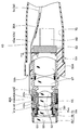
- FIG. 5 is a diagram for explaining a configuration of a distal bending piece portion that constitutes a bending portion of an insertion portion, and is a cross-sectional view taken along line Y3-Y3 in FIG.
- FIG. 3 is an enlarged cross-sectional view taken along the line Y5A-Y5A in FIG. 2 for explaining an actuator unit that also functions as a drive mechanism and a fog prevention function.
- FIG. 5A Enlarged view of the portion indicated by arrow Y5C in FIG. 5A
- FIG. 9 is a cross-sectional view taken along arrow Y10-Y10.
- produces electromagnetic waves in the outer peripheral surface of the 1st objective lens frame which fixes a front-end lens, the 1st space
- the endoscope system 1 mainly includes, for example, an endoscope 10, a processor 2, and a display device 3.
- the endoscope 10 includes an insertion part 11, an operation part 12, and a universal cord 13.
- a distal end portion 14 is provided on the distal end side of the insertion portion 11.
- a tip lens 51 is disposed on the tip surface of the tip portion 14.
- the tip lens 51 is a first lens of the imaging unit 50 that is a lens unit.
- the front end lens 51 has a front end surface exposed to the outside of the endoscope 10 and is fixedly held by the first objective lens frame 4a.
- the imaging unit 50 is provided with a movable lens 52 that can advance and retract with respect to the optical axis direction for focusing or zooming.
- the movable lens 52 is fixedly held on the movable lens frame 4d.
- the movable lens frame 4d is driven back and forth by an actuator unit 40 which is a lens driving unit.
- the actuator unit 40 is provided with a heat generating / driving combined coil (hereinafter abbreviated as a combined coil) 43 that serves as both lens driving means and heat generating means.
- a combined coil a heat generating / driving combined coil
- a thermistor 5 serving as a temperature detecting means is disposed in the vicinity of the distal end lens 51 of the distal end portion 14.
- a flexible substrate 30 is extended from the thermistor 5 toward the base end side. As shown in FIG. 5A, a pair of sensor wires 6a and 6b and a pair of dual-purpose wires 6c and 6d are connected to the base end of the flexible substrate 30.
- the sensor wires 6a and 6b and the dual-purpose wires 6c and 6d are grouped as an actuator cable 6 as shown in FIG.
- the actuator cable 6 passes through the distal end portion 14, the bending portion 15, the operation portion 12, and the universal cord 13 constituting the insertion portion 11, and extends to an endoscope connector (not shown).
- the operation unit 12 is provided with a first switch 12a and a second switch 12b.
- the first switch 12a is a lens position switching switch.
- the first switch 12a outputs an instruction signal for switching the arrangement position of the movable lens 52 between a distal end position on the distal lens 51 side and a proximal end position in the opposite direction.
- the second switch 12b is a fog prevention switch.
- the second switch 12b outputs an instruction signal for heating the front lens 51 in order to prevent the front lens 51 from being fogged.
- a first switch cable 7 extends from the first switch 12a, and a second switch cable 8 extends from the second switch 12b.
- the switch cables 7 and 8 are inserted into the operation unit 12 and the universal cord 13 and extended to an endoscope connector (not shown).
- the processor 2 is provided with a control circuit 2a.
- the control circuit 2a is provided with a movable lens control unit 2b, a temperature detection unit 2c, a heat generation control unit 2d, an image processing circuit (not shown), and the like.
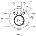
- a tip lens 51 and, for example, a pair of illumination lenses 14 a and 14 b are provided on the tip surface 14 f of the tip portion 14.
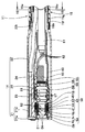
- a bending portion 15 shown in FIGS. 3 and 4 is provided on the proximal end side of the distal end portion 14 constituting the insertion portion 11.
- the distal end portion 14 is configured by integrating a substantially cylindrical first distal end frame member 21, a tubular second distal end frame member 22, and a columnar distal end constituent member 23.
- the first tip frame member 21 and the second tip frame member 22 are made of, for example, stainless steel.
- the tip component member 23 is made of copper having higher thermal conductivity than stainless steel, for example, in consideration of thermal conductivity.
- the first tip frame member 21 has a main body portion 21a and an annular portion 21b.
- One surface of the main body portion 21 a constitutes a distal end surface 14 f of the distal end portion 14.
- the annular portion 21b protrudes from the other surface side of the main body portion 21a with a predetermined size.
- the outer diameter of the annular portion 21b is set to a predetermined size and a smaller diameter than the outer diameter of the main body 21a.
- through holes 21h1, 21h2, and 21h3 are formed in the main body portion 21a.
- the central axes of the through holes 21h1, 21h2, and 21h3 are arranged in parallel to the longitudinal axis of the insertion portion.
- the first objective lens frame 4a is disposed in the first through hole 21h1.
- the first illumination lens 14a is disposed in the second through hole 21h2.
- a second illumination lens 14b is disposed in the third through hole 21h3.
- the second tip frame member 22 constitutes the outer surface of the tip portion 14.
- the inner peripheral surface of the second tip frame member 22 is fixed to the outer peripheral surface of the annular portion 21b.
- the outer diameter dimension of at least the distal end side of the second distal end frame member 22 fixed to the annular portion 21b is substantially the same as the outer diameter dimension of the main body portion 21a.
- a small diameter portion 22 t is formed on the proximal end side of the second distal end frame member 22.
- a distal end portion of a distal bending piece 15f constituting the bending portion 15 is fixed to the small diameter portion 22t.
- the distal ends of the bending wires 15u, 15d, 15r, and 15l shown in FIGS. 3 and 4 are fixed at predetermined positions on the inner peripheral surface of the distal bending piece 15f.
- a reticulated tube (not shown) and a bending rubber 15g are coated on the outer peripheral side of a bending piece set 15C configured by connecting a plurality of bending pieces (not shown) including the tip bending piece 15f.
- the end portion of the curved rubber 15g is fixed to the small diameter portion 21t by providing a bobbin adhering portion 15b.
- the tip component member 23 is formed with an imaging unit through-hole 24, a heat radiation wire through-hole 25, a first light guide through-hole and a second light guide through-hole not shown.
- the central axis of each through-hole is parallel to the insertion portion longitudinal axis.
- the notch groove 26 shown in FIGS. 5A and 5B is formed in the tip component member 23.
- the cutout groove 26 has a thin substrate storage groove 26a and a thermistor installation recess 26b along the insertion portion longitudinal axis direction.
- the thermistor installation recess 26b is provided at the tip of the substrate storage groove 26a.
- the flexible substrate 30 is accommodated in the substrate accommodating groove 26a. Although not shown, the flexible substrate 30 is provided with a thermistor contact, a coil connection contact, a wiring terminal, and a wiring portion for connecting each contact to each terminal.
- the thermistor 5 is disposed in the thermistor installation recess 26b in order to detect the temperature of the tip lens 51.
- the thermistor 5 is connected to a thermistor contact provided on the tip side of the flexible substrate 30.
- the temperature detection surface 5f of the thermistor 5 is in close contact with the bottom surface of the thermistor installation recess 26b.
- a plurality of wiring terminals are provided on the base end side of the flexible substrate 30. Each wiring terminal is connected to the leading ends of sensor wirings 6a and 6b inserted into the actuator cable 6 and the leading ends of dual-purpose wirings 6c and 6d.
- the detection value of the thermistor 5 is output to the temperature detection unit 2c of the control circuit 2a via the flexible substrate 30 and the sensor wires 6a and 6b.
- the shared coil 43 is electrically connected to the flexible substrate 30.
- the output from the movable lens control unit 2b of the control circuit 2a is supplied to the dual-purpose coil 43 via the dual-purpose wirings 6c and 6d, the flexible substrate 30, and the like.
- the first light guide fiber bundle (reference numeral 31 in FIG. 3) facing the first illumination lens 14a is inserted into the first light guide through hole.
- a second light guide fiber bundle (reference numeral 32 in FIG. 3) facing the second illumination lens 14b is inserted into the second light guide through hole.
- the heat radiating wire 33 is a heat radiating member and is set to a predetermined length dimension.
- the heat radiation wire 33 radiates heat generated in the distal end portion 14 of the light guide fiber bundles 31 and 32 toward the proximal end side of the insertion portion 11.
- the distal end portion of the heat radiation wire 33 is disposed between the first illumination lens 14a and the second illumination lens 14b (see the broken line in FIG. 2).
- the heat radiation wire 33 is formed by bundling a plurality of wires having high thermal conductivity, such as thin copper wires, aluminum wires, or silver wires, in consideration of both heat capacity and workability.
- the diameter of the heat radiation wire 33 is appropriately set in consideration of the inner diameter of the insertion portion 11, the outer diameter of the endoscope built-in object inserted into the insertion portion 11, the position, and the like.
- symbol 61 is an imaging cable and is extended from the imaging unit 50.
- FIG. A plurality of signal lines 62 are inserted into the imaging cable 61.
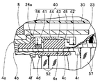
- the imaging unit 50 is disposed in the imaging unit through hole 24.
- the imaging unit 50 includes an imaging element 53, an objective optical system unit 54, an imaging optical system unit 55, and an actuator unit 40 as shown in FIGS. 4 and 5A.
- the objective optical system unit 54 includes an objective lens frame 4 including a first objective lens frame 4a, a second objective lens frame 4b, and a third objective lens frame 4c that are formed in a predetermined shape, and a movable lens frame 4d. It is equipped with.
- a tip lens 51 is fixed to the inner peripheral surface on the tip side of the first objective lens frame 4a.
- the outer peripheral surface on the distal end side of the second objective lens frame 4b is fitted and fixed to the inner peripheral surface on the proximal end side of the first objective lens frame 4a.
- a plurality of optical lenses 56 and the like are fixed to the inner peripheral surface of the second objective lens frame 4b.
- the inner peripheral surface on the distal end side of the third objective lens frame 4c is fitted and fixed to the outer peripheral surface on the proximal end side of the second objective lens frame 4b.
- a plurality of optical lenses 57 and the like are fixed to the inner peripheral surface on the proximal end side of the third objective lens frame 4c.
- the outer peripheral surface of the movable lens frame 4d is movably held on the inner peripheral surface on the distal end side of the third objective lens frame 4c.
- a movable lens 52 is fixed to the inner peripheral surface of the movable lens frame 4d.
- the first objective lens frame 4a and the second objective lens frame 4b are heat conducting members and are formed of a metal member such as brass or stainless steel having a high thermal conductivity.
- the third objective lens frame 4c is a heat conducting member.
- the third objective lens frame 4c is provided with an actuator unit 40. For this reason, the third objective lens frame 4c does not interfere with the magnetic force for driving the movable lens frame 4d from the actuator unit 40, and in order to efficiently transmit the magnetic force from the actuator unit 40 to the movable lens frame 4d.
- It is made of a metal member having a high conductivity and a non-magnetic material such as brass or stainless steel.
- the heat from the actuator unit 40 is transmitted from the third objective lens frame 4c to the second objective lens frame 4b, and further transmitted from the second objective lens frame 4b to the tip lens 51 via the first objective lens frame 4a.
- the movable lens frame 4d is slidably disposed in the inner peripheral surface of the tip in the inner hole of the third objective lens frame 4c.
- the movable lens frame 4d moves under the magnetic force from the actuator unit 40.
- the movable lens frame 4d is formed of a magnetic material such as carbon steel or electromagnetic steel.
- the imaging optical system unit 55 is configured by fixing a cover glass 58 to an imaging frame 59.
- An imaging element 53 is fixed to the base end side of the imaging frame 59 via a cover glass 58.
- the imaging frame 59 is formed of, for example, ceramic or resin, which is a member having insulating properties and low thermal conductivity.
- the image sensor 53 is electrically connected to the circuit board 60.
- a plurality of signal lines 62 are connected to the circuit board 60.
- the plurality of signal lines 62 are gathered together and passed through the insertion portion 11, the operation portion 12, and the universal cord 13 as an imaging cable 61 and extended to the endoscope connector.
- Reference numeral 70 denotes a shield frame.
- the shield frame 70 covers and protects the image sensor 53.
- the inner periphery on the distal end side of the shield frame 70 is fitted and fixed to the outer periphery on the proximal end side of the imaging frame 59.
- Reference numeral 63 denotes an imaging unit exterior frame that covers the imaging unit.
- the imaging unit exterior frame 63 is a heat-shrinkable tube that is shrunk by heat, for example.
- the imaging unit exterior frame 63 is filled with sealing resin. That is, the periphery of the imaging element 53, the circuit board 60, and the cable 61 is covered with the sealing resin.
- the imaging unit 59 is configured by fixing the imaging frame 59 to the third objective lens frame 4c.
- the actuator unit 40 includes a first permanent magnet 41, a second permanent magnet 42, a dual-purpose coil 43, a first yoke 44, and a second yoke 45.
- the first permanent magnet 41 and the second permanent magnet 42 are arranged in the optical axis direction, and are adjacent to the side surface of the first yoke 44 and the side surface of the second yoke 45 with the dual-purpose coil 43 interposed in the central axis direction of the imaging unit 50. Is provided.
- a unit outer peripheral step (hereinafter referred to as a step) 4g which is a step protruding outward from the tip outer periphery 4e, is formed at a predetermined position on the outer periphery of the third objective lens frame 4c.
- a base end side contact portion 4r that is a circumferential convex portion projecting in the central axis direction of the imaging unit 50 is formed.
- the movable lens frame 4d is held at the second holding position by the base end surface of the movable lens frame 4d retracted in the optical axis direction coming into contact with the base end side contact portion 4r that is the second position restricting portion.
- the actuator unit 40 is configured on the outer periphery of the third objective lens frame 4c.
- a conductor coil 43 is formed on the periphery of the tip outer periphery 4e by winding a conducting wire.
- a conducting wire for forming the combined coil 43 is directly wound around the outer periphery of the third objective lens frame 4c.
- the dual-purpose coil 43 is not limited to this configuration, and may have a configuration in which a conducting wire is indirectly wound around the outer periphery of the third objective lens frame 4c via, for example, an insulating member.
- yokes 44 and 45 are disposed so as to cover the dual-purpose coil 43.
- the second yoke 45 is provided so as to abut on the stepped portion 4g in the optical axis direction and in the central axis direction of the imaging unit 50.
- the first yoke 44 is provided so as to abut against the second yoke 45.
- the yokes 44 and 45 are formed of a magnetic material such as carbon steel or electromagnetic steel, and are provided so as to cover the dual-purpose coil 43 in order to efficiently transmit the magnetic force generated by the dual-purpose coil 43 to the movable lens frame 4d.
- yokes 44 and 45 are provided so as to cover the dual-purpose coil 43.
- the yokes 44 and 45 are formed in a cylindrical shape, and the yokes 44 and 45 are in the optical axis direction and in the central axis direction of the imaging unit 50, the tip outer periphery 4 e between the dual-purpose coil 43 and the first permanent magnet 41.
- the optical axis direction of the first permanent magnet 41 and the second permanent magnet 42 may be provided adjacent to the outside in the central axis direction of the imaging unit 50. Further, if the magnetic force generated by the dual-purpose coil 43 can generate a magnetic force sufficient to move the movable lens frame 4d, the yokes 44 and 45 need not be provided.
- a cylindrical first permanent magnet 41 is fixedly provided adjacent to the first yoke 44 in the optical axis direction and on the front end side of the first yoke 44 in the central axis direction of the imaging unit 50.
- a cylindrical second permanent magnet 42 is fixedly provided adjacent to the second yoke 45 on the proximal end side with respect to the second yoke 45 in the central axis direction of the imaging unit 50 in the optical axis direction.
- the second permanent magnet 42 is held with its inner periphery fitted to the outer periphery of the third objective lens frame 4c on the proximal side from the step 4g.
- the first permanent magnet 41 and the second permanent magnet 42 are preferably the same size. Further, in order for the inner diameter of the first permanent magnet 41 to be substantially the same as the inner diameter of the second permanent magnet 42, the first permanent magnet 41 is interposed via a spacer 46 made of a non-magnetic material. It is fixed to the tip outer periphery 4e.
- a spacer 46 is provided in order to make the inner peripheral diameters of the first permanent magnet 41 and the second permanent magnet 42 substantially the same.
- a protrusion having the same shape as the spacer 46 may be formed on the third objective lens frame 4c. In this fixed state, for example, the N pole of the first permanent magnet 41 and the N pole of the second permanent magnet 42 face each other.
- the polarities (S / N) of the first permanent magnet 41 and the second permanent magnet 42 are respectively arranged in the moving direction of the movable lens frame 4d, and the first permanent magnet 41 and the second permanent magnet 41 are arranged.
- the first permanent magnet 41 and the second permanent magnet 42 are disposed so that the opposing surfaces of the magnet 42 have the same polarity.
- the present invention is not limited to this.
- the polarities (S / N) of the first permanent magnet 41 and the second permanent magnet 42 are arranged in a direction orthogonal to the moving direction of the movable lens frame 4d.
- the first permanent magnet 41 and the second permanent magnet 42 are arranged so that the polarities located on the movable lens frame 4d side are the same in the first permanent magnet 41 and the second permanent magnet 42. It may be.
- the permanent magnets 41 and 42 are cylindrical. However, a plurality of permanent magnets 41 and 42 may be arranged on the outer periphery 4e of the tip, for example.
- the second yoke 45 is abutted against the stepped portion 4g, and the first yoke 44 and the first permanent magnet 41 are disposed on the tip side of the second yoke 45.
- a second permanent magnet 42 is abutted and fixed on the base end side of the second yoke 45.
- a plurality of conductive wires made of, for example, copper wire are wound around the tip outer periphery 4e.
- the combined coil 43 is provided.
- One end portion 43 a of the conductive wire constituting the dual-purpose coil 43 is connected to one coil connection terminal of the flexible substrate 30, and the other end portion 43 b is connected to the other coil connection terminal of the flexible substrate 30.
- the dual-purpose coil 43 and the control circuit 2a are connected to each other via one end portion 43a, the other end portion 43b, the flexible substrate 30, and the dual-purpose wirings 6c and 6d.
- a notch 4h is provided.
- One end portion 43a and the other end portion 43b of the conducting wire pass through a gap formed by the inner periphery of the second permanent magnet 42 and the cutout 4h of the third objective lens frame 4c, and are connected to the coil connection terminals of the flexible substrate 30. Is done.
- Numeral 4f is a front end side contact portion, which is a first position restricting portion.
- the front end surface of the movable lens frame 4d that is advanced contacts the front end side contact portion 4f.
- the movable lens frame 4d is held in the first holding position in contact with the front end side contact portion 4f.
- the front end side contact portion 4f is a portion protruding in a direction orthogonal to the central axis of the third objective lens frame 4c, for example, a base end portion of the second objective lens frame 4b.
- the base end portion of the second objective lens frame 4b protrudes circumferentially from the inner hole surface of the third objective lens frame 4c to form a convex portion.
- the movable range of the movable lens frame 4d in the optical axis direction is defined by the distal end side contact portion 4f and the proximal end side contact portion 4r.
- the second objective lens frame 4b provided with the distal end side contact portion 4f and the third objective lens frame 4c provided with the proximal end side contact portion 4r are arranged such that the distal end surface of the third objective lens frame 4c is first.
- the mutual positions in the optical axis direction and in the central axis direction of the imaging unit 50 are determined.
- the positions of the distal end side contact portion 4f and the proximal end side contact portion 4r can be arranged with high accuracy, and the movable range of the movable lens frame 4d in the optical axis direction can be set with high accuracy.
- the distal end side contact portion 4f on which the movable lens frame 4d abuts is provided on the second objective lens frame 4b, and the proximal end side contact portion 4r is provided on the third objective lens frame 4c.
- the configuration is not limited thereto, and for example, a dedicated contact member having any one of the contact portions may be provided.
- a movable range of the movable lens frame 4d may be adjustable by providing a member having any one of the contact portions so that the position in the optical axis direction can be adjusted.
- Reference numeral 23S in FIG. 5A is an adiabatic space.
- the heat insulating space 23 ⁇ / b> S is a heat insulating layer that prevents heat generated from the dual-purpose coil 43 from being conducted to the tip component member 23.
- the heat insulating layer is an air layer.
- the heat insulating layer may be filled with a resin having low thermal conductivity.
- Numeral 4j is a filler.
- the filler 4j is filled in a portion surrounded by the first objective lens frame 4a, the second objective lens frame 4b, the third objective lens frame 4c, and the first permanent magnet 41. Yes.
- the filler 4j is a heat transfer layer, and guides the heat generated from the dual-purpose coil 43 and conducted to the third objective lens frame 4c to the optical lens 56 and the tip lens 51.
- the imaging unit 50 of the endoscope 10 acquires a wide range of endoscopic images when the movable lens frame 4d is in contact with, for example, the distal end side contact portion 4f, When the movable lens frame 4d is in contact with the proximal end side contact portion 4r, an endoscope image in a narrow range is acquired.
- the imaging unit 50 is set so that the movable lens frame 4d comes into contact with the distal end side contact portion 4f so as to acquire a wide range of endoscope images when the endoscope 10 is powered on.
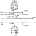
- the voltage E1 is applied to bring the movable lens frame 4d into contact with the front end side contact portion 4f and hold it at the first holding position.
- the voltage E1 is the first voltage, and is the minimum voltage required to hold the movable lens frame 4d from the movable lens control unit 2b to the dual-purpose coil 43 in contact with the distal end side contact portion 4f, or more than that. It is a large voltage.
- the current output from the movable lens control unit 2b is supplied in the order of the first combined wiring 6c, the one end portion 43a of the conductive wire, the combined coil 43, the other end portion 43b of the conductive wire, and the second combined wiring 6d.
- the magnetic field of the second permanent magnet 42 is canceled by the magnetic field of the dual-purpose coil 43, and the magnetic field of the dual-purpose coil 43, the magnetic field of the first permanent magnet 41, and the movable lens frame 4d are magnetically engaged.
- the movable lens frame 4d is held at the first holding position in contact with the front end side contact portion 4f.
- the surgeon observes the affected part that is, obtains an endoscopic image in a narrow range
- the operator operates the first switch 12a provided in the operation part 12. Then, an instruction signal for switching the position of the movable lens frame 4d is output from the first switch 12a to the processor 2.
- the current is transferred from the movable lens control portion 2b in a direction different from the above.
- a voltage E1 which is a first voltage which is at least necessary or higher than the first voltage.
- the current is supplied from the movable lens control unit 2b in the order of the second combined wiring 6b, the other end 43b of the conductive wire, the combined coil 43, the one end 43a of the conductive wire, and the first combined wiring 6c.
- the magnetic field of the first permanent magnet 41 is canceled by the magnetic field of the dual-purpose coil 43, and the magnetic field of the dual-purpose coil 43, the magnetic field of the second permanent magnet 42, and the movable lens frame 4d are magnetically engaged.
- the movable lens frame 4d is held at the second holding position in contact with the base end side contact portion 4r.
- the voltage applied to the dual-purpose coil 43 is + E1 when the current is supplied in the order of the first dual-purpose wiring 6c, the one end 43a of the conductive wire, the dual-purpose coil 43, the other end 43b of the conductive wire, and the second dual-purpose wiring 6d
- the current is supplied in the order of the second combined wiring 6d, the other end portion 43b of the conductive wire, the combined coil 43, the one end portion 43a of the conductive wire, and the first combined wiring 6c, ⁇ E1 is assumed.
- the relationship between the moving direction of the movable lens frame 4d and the direction of current flow can be expressed. That is, the absolute value of the voltage applied to the dual purpose coil 43 is the same.
- the control circuit 2a that receives the instruction signal from the first switch 12a has the movable lens control unit 2b. Then, a current is supplied in a direction different from the above, and a voltage of + E1 is applied to the dual-purpose coil 43.
- the movable lens frame 4d is held again from the second holding position at the first holding position where the movable lens frame 4d is in contact with the front end side contact portion 4f.
- the first voltage (E1 or -E1) applied to the dual purpose coil 43 is a voltage sufficient to hold at the first holding position or the second holding position. For this reason, when moving from the first holding position to the second holding position, or when moving in the opposite direction, a voltage having an absolute value greater than the first voltage (E1 or -E1) is applied to the dual-purpose coil 43. May be applied.
- the control circuit 2a that receives the instruction signal from the first switch 12a receives the movable lens. Control is performed so that a voltage having an absolute value larger than the first voltage (E1 or -E1) is applied from the control unit 2b for a predetermined period required for movement.
- the absolute value of the first voltage applied to the dual-purpose coil 43 is set to the same value (E1). If so. However, if the voltage is the minimum necessary to hold the movable lens frame 4d at the first holding position or the second holding position, the absolute value of the first voltage applied to the dual-purpose coil 43 is the movable lens. Different values may be used when the frame 4d is held at the first holding position and when the frame 4d is held at the second holding position.
- the function of preventing the tip lens 51 from fogging will be described with reference to FIGS. 5A and 7.
- the temperature near the distal lens 51 provided at the distal end portion 14 of the insertion portion 11 of the endoscope 10 is detected by the thermistor 5.
- the detection value detected by the thermistor 5 is configured to be output to the temperature detection unit 2c.
- the temperature is set so that the thermistor 5 detects the temperature in the vicinity of the distal lens 51 at the same time when the endoscope 10 is turned on.
- the movable lens frame 4d is held in a state of being in contact with the distal end side contact portion 4f.
- the surgeon operates the second switch 12b provided in the operation unit 12 when preventing clouding. Then, an instruction signal for heating the tip lens 51 is output from the second switch 12 b to the processor 2.
- the operation in which the instruction signal for heating the distal lens 51 is output to the processor 2 is not limited to the operation of the operator's second switch 12b.
- an instruction signal may be output from the processor 2 only for a certain period when the processor 2 is powered on.
- the control circuit 2a that has received the instruction signal, the detected temperature C1 detected by the thermistor 5 and the lens temperature C0 that is a specified value registered in a storage unit (not shown) provided in the heat generation control unit 2d. And the comparison result is determined by a determination unit (not shown).
- the heat generation control unit 2d does not perform any control, and the dual-purpose coil 43 has no control as shown by the two-dot chain line in FIG.
- the voltage output from the movable lens control unit 2b is continuously applied.
- the lens temperature C0 is a temperature that is set in advance so that the tip lens 51 is not fogged when performing endoscopic observation.
- the heat generation control unit 2d has an absolute value greater than the voltage output from the movable lens control unit 2b to the movable lens control unit 2b.
- An instruction signal for applying a large voltage to the dual-purpose coil 43 is output.
- the voltage + E2 which is a second voltage higher than + E1 registered in advance in the storage unit as shown by the solid line in FIG. Applied to the dual-purpose coil 43.
- the voltage value registered in the storage unit is not limited to one of + E2, and a plurality of voltage values may be registered in the storage unit for each temperature difference between the detected temperature C1 and the lens temperature C0.
- the dual-purpose coil 43 to which the voltage + E2 is applied increases the amount of heat generation while maintaining the state in which the movable lens frame 4d is in contact with the distal end side contact portion 4f.
- the heat generated from the dual-purpose coil 43 is transmitted through the third objective lens frame 4c, the second objective lens frame 4b, and the first objective lens frame 4a as shown by the arrow 5Y in FIG. 5A.
- Heat conduction to the optical lens 56 increases the temperature of the tip lens 51.
- the heat generation control unit 2d supplies the original voltage + E1 ( ⁇ E1) to the movable lens control unit 2b. ) Is output to the dual-purpose coil 43. Then, the voltage applied to the shared coil 43 from the movable lens control unit 2b is switched to + E1 ( ⁇ E1).
- the movable lens control unit 2b applies the voltage -E2 as the second voltage to the dual purpose coil 43 when the voltage -E1 indicated by the alternate long and short dash line is applied to the dual purpose coil 43. Control to raise the temperature of 51 is performed.
- the voltage applied to the dual-purpose coil 43 is changed.
- the current value may be changed. That is, the amount of heat generated from the dual-purpose coil 43 is changed by changing the power supplied to the dual-purpose coil 43.
- the heat generation control unit 2d is output from the movable lens control unit 2b to the movable lens control unit 2b.
- An instruction signal for applying a second voltage (E2 or -E2) having a larger absolute value than the first voltage (E1 or -E1) to the combined coil 43 is output.
- the second lens 12b is operated to move the movable lens control unit 2b to a predetermined constant value.
- the second voltage (E2 or -E2) having an absolute value larger than the first voltage (E1 or -E1) may be applied to the shared coil 43 only for the period. In this configuration, the thermistor 5 may not be provided.
- the absolute value of the second voltage applied to the dual-purpose coil 43 to remove fogging are set to the same value (E2).
- the absolute value of the second voltage applied to the dual-purpose coil 43 is a voltage necessary to remove fogging, the movable lens frame 4d is held in the first holding position, Different values may be used depending on the state held at the holding position.
- the dual-purpose coil 43 that serves as both the lens drive means coil and the heat generation means heater coil is provided.
- the temperature sensor wires 6a and 6b in addition to the temperature sensor wires 6a and 6b, six wires of heater wires 81 and 82 and drive wires 84 and 85 are inserted into the actuator cable 80.
- the temperature sensor wirings 6a and 6b and the dual-purpose wirings 6c and 6d are inserted into the actuator cable 6 as shown in FIG. 8B, and either the heater wiring or the driving wiring is used. Is no longer necessary.
- the outer diameter ⁇ D1 of the actuator cable 6 is smaller than the outer diameter ⁇ D2 of the actuator cable 80. Therefore, the insertion portion inner diameter ⁇ D3 through which the actuator cable 6 and the imaging cable 61 are inserted can be made thinner than the actuator cable 80 and the insertion portion inner diameter ⁇ D4 through which the imaging cable 61 is inserted. As a result, the outer diameter of the insertion portion 11 is prevented from becoming large, and the connection workability can be improved by reducing the number of wires.
- the dual-purpose coil 43 is provided in the outer periphery 4e of the distal end of the third objective lens frame 4c, so that it is not necessary to separately provide the lens driving means and the heat generating means at the distal end portion.
- the diameter can be reduced.
- the first objective lens frame 4a, the second objective lens frame 4b, and the third objective lens frame 4c are formed of a metal member having high thermal conductivity, and the imaging frame 59 is heated by the three objective lens frames 4a, 4b, and 4c.
- it is made of a ceramic resin having a low conductivity.
- the heat generated from the dual-purpose coil 43 is efficiently conducted to the front end via the third objective lens frame 4c, the second objective lens frame 4b, and the first objective lens frame 4a without being conducted to the imaging frame 59 side. Conduction to the lens 51 is possible. In addition, heat from the dual-purpose coil 43 can be prevented from being conducted to the image sensor 53.
- the thermistor 5 is disposed in the vicinity of the front end lens 51 to indirectly detect the temperature of the front end lens 51.
- the arrangement position of the temperature detection means such as the thermistor is not limited to the inside of the thermistor installation recess 26 b formed in the tip component member 23.
- a thermistor through hole orthogonal to the optical axis may be formed in the tip component member 23 instead of the thermistor installation recess 26b, and the temperature detection surface 5f of the thermistor 5 may be brought into close contact with the first objective lens frame 4a.
- a groove parallel to the optical axis is formed in the first objective lens frame 4a and has an opening that opens in the through hole for the thermistor so that the temperature detection surface 5f of the thermistor 5 is in direct contact with the tip lens 51. Good.
- the heat generated from the dual-purpose coil 43 is generated by 3 of the first objective lens frame 4a, the second objective lens frame 4b, and the third objective lens frame 4c, which are the objective lens frame 4. It is assumed that the light is conducted to the tip lens 51 through the two objective lens frames 4a, 4b, and 4c.
- the objective lens frame 4 is formed by integrating at least any one of the first objective lens frame 4a, the second objective lens frame 4b, and the third objective lens frame 4c. Also good.
- the objective lens frame 4 may be formed by dividing at least one of the first objective lens frame 4a, the second objective lens frame 4b, and the third objective lens frame 4c.
- the tip lens 51 is provided on one or one objective lens frame
- the actuator unit 40 is provided on the outer periphery of one or one objective lens frame.
- the imaging unit 50 is connected to the flexible substrate 30 in which the one end portion 43 a and the other end portion 43 b of the conductive wire constituting the dual-purpose coil 43 are arranged outside the imaging unit 50.
- the thermistor 5 is mounted on one end side of the flexible substrate 30.
- one end portion 43 a and the other end portion 43 b of the conducting wire constituting the dual-purpose coil 43 are accommodated in the imaging unit 50, and the one end portion 43 a and the other end portion 43 b of the conducting wire are placed outside the imaging unit 50.
- the assembly work is improved by eliminating the need to connect to the flexible board located at the position.
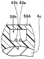
- the imaging unit 50A includes an imaging element 53, an objective optical system unit 54A, an imaging optical system unit 55A, and an actuator unit 40A.
- the imaging frame 59A constituting the imaging optical system unit 55A is provided with a conductor hole 59h.
- the one end portion 43a and the other end portion 43b of the conducting wire constituting the dual purpose coil 43 are guided into the imaging unit exterior frame 63 through the conducting wire hole 59h.
- a flexible substrate 30A is disposed in the imaging unit exterior frame 63.
- the flexible substrate 30A is provided with a coil connection terminal to which the one end portion 43a and the other end portion 43b of the conducting wire are respectively connected.
- the one end portion 43a and the other end portion 43b of the conducting wire are respectively connected to coil connection terminals provided on the flexible substrate 30A.
- the flexible substrate 30A is disposed in the imaging unit exterior frame 63, and the one end portion 43a and the other end portion 43b of the conductor constituting the combined coil 43 in the imaging frame 59A are guided into the imaging unit exterior frame 63.
- a hole 59h is provided.
- the one end part 43a and the other end part 43b of the conducting wire led in the imaging unit exterior frame 63 are respectively connected to the coil connection terminals of the flexible substrate 30A.
- the one end portion 43a and the other end portion 43b of the conducting wire are connected to the coil connection terminals of the flexible substrate 30A.
- a coil connection terminal for connecting the one end portion 43a and the other end portion 43b of the conducting wire may be provided on the circuit board 60 without providing the flexible substrate 30A. That is, in the present embodiment, the circuit board 60 may be configured to also serve as the flexible board 30A.
- a chamfer 4ac for filling the adhesive 90 is provided on the base end side of the first objective lens frame 4a1.
- the adhesive 90 is for reducing moisture intrusion into the imaging optical system unit 55.
- both the first permanent magnet 41A and the second permanent magnet 42A are fitted into the outer periphery on the tip side of the third objective lens frame 4c.
- the spacer 46 for making the internal diameter of the 1st permanent magnet 41A and the internal diameter of the 2nd permanent magnet 42A the same can be made unnecessary.
- a notch 45Ac is provided in the second yoke 45A disposed on the base end side in order to extend the end portions 43a and 43b of the conducting wire constituting the dual purpose coil 43 to the outside of the actuator unit 40. ing.
- the first yoke 44A disposed on the front end side. Also, a similar notch 44Ac is provided so as to have the same shape as the second yoke 45A.
- a coil as a lens driving unit is not necessary.
- heat generation means can be provided as shown in FIG. 11 to prevent the occurrence of fogging on the surface of the front lens or to remove the generated fogging.
- a coil 91 that generates electromagnetic waves is provided on the outer peripheral surface of the first objective lens frame 4a2 that fixes the tip lens 51 constituting the imaging unit 50B.
- the first objective lens frame 4a2 is formed of stainless steel that is a non-magnetic material.
- the second objective lens frame 4b2 having a plurality of optical lenses 92 and a plurality of spacing rings 93, 94, 95 fixed thereto is fixed to the inner peripheral surface of the first objective lens frame 4a2.
- the first spacing ring 93 is fixed to the front end surface of the second objective lens frame 4b1.
- the distal end surface of the first interval ring 93 is disposed in close contact with a diaphragm 96 disposed on the proximal end surface side of the distal end lens 51.
- the second objective lens frame 4b2 and the first spacing ring 93 are made of magnetic material such as carbon steel, and the second spacing ring 94 and third spacing ring 95 are made of non-magnetic material such as stainless steel. Yes.
- the imaging frame 59 made of a ceramic resin to which the imaging element 53 is fixed via the cover glass 58 is the same as in the above-described embodiment. Is fixed.
- the imaging unit 50B provided with the coil 91 that generates the electromagnetic wave on the outer peripheral surface of the first objective lens frame 4a2, the current is passed through the coil 91 to generate the electromagnetic wave, thereby being disposed in the vicinity of the coil 91.
- the heat generated in the first interval ring 93 and the heat generated in the second objective lens frame 4b2 are conducted to the front lens 51 through the diaphragm 96, and the temperature of the lens 51 rises to prevent the occurrence of fogging. Alternatively, the generated haze is removed.
- the diaphragm 97 shown in the enlarged view of the B portion shown in FIG.
- an opening 97m is formed by etching.
- the diaphragm 97 can be manufactured thin with high accuracy.
- the curved surface 92r side of the optical lens 92 is disposed on the sag surface 97a side (opening large diameter side) during etching.
- the curved surface 92r of the optical lens 92 is applied to the sag surface 97a of the diaphragm 97 in a stable state.
Abstract
The endoscope of the present invention has: a first lens positioned at a distal end, a portion of the first lens being exposed to the outside; a movable lens frame capable of moving, for retaining a movable lens provided closer to a proximal end than the first lens; an actuator unit having a coil supplied with electric power and thereby driving the movable lens frame and generating heat; and an objective lens frame for retaining the movable lens frame therein so that the movable lens frame can move, retaining the first lens and the actuator unit, and conducting the heat generated from the coil to the first lens.
Description
本発明は、先端レンズに曇りが発生することを防止した内視鏡及び内視鏡システムに関する。
The present invention relates to an endoscope and an endoscope system that prevent the tip lens from fogging.
内視鏡は、医療分野、工業分野等において用いられている。内視鏡には、挿入部の先端部に撮像ユニットを内蔵した、いわゆる電子式内視鏡(以下、内視鏡と記載する)がある。
Endoscopes are used in the medical and industrial fields. An endoscope includes a so-called electronic endoscope (hereinafter referred to as an endoscope) in which an imaging unit is built in a distal end portion of an insertion portion.
内視鏡においては、観察部位、或いは、観察の目的等によって観察対象部に対する焦点深度、結像倍率、視野角等、光学特性を変更することを可能な撮像ユニットが望まれている。
In an endoscope, there is a demand for an imaging unit capable of changing optical characteristics such as a depth of focus, an imaging magnification, and a viewing angle with respect to an observation target part depending on an observation site or an observation purpose.
内視鏡が挿入される例えば体腔内は、温度約35~37℃、湿度約98~100%という環境下である。このため、挿入部を体腔内に挿入した際、内視鏡検査室と体腔内との温度差に起因して、挿入部先端面に位置する先端レンズ表面に結露が起こり、曇りが生じるおそれがあった。
For example, the inside of a body cavity where an endoscope is inserted is in an environment of a temperature of about 35 to 37 ° C. and a humidity of about 98 to 100%. For this reason, when the insertion portion is inserted into the body cavity, condensation may occur on the surface of the distal lens located on the distal end surface of the insertion portion due to a temperature difference between the endoscopic examination room and the body cavity, and clouding may occur. there were.
このため、内視鏡観察においては、観察等の妨げとなり得る曇りの発生の防止、或いは、発生した曇りの除去が可能な内視鏡が望まれている。
For this reason, in endoscope observation, an endoscope capable of preventing the occurrence of fogging that can hinder observation or the like or removing the generated fogging is desired.
例えば、日本国特開2004-325603号公報には、カメラの結露または氷結対策の技術が開示されている。この技術では、例えば、前面レンズの平坦面と、第2レンズの平坦面との間に、撮像光路に影響が出ない領域にフィルム状のヒータが環状に挟まるように設けられ、レンズホルダの内壁面にはレンズモジュール内の温度を取得する温度センサが設けられている。レンズモジュールは、温度センサの出力に基づいて、ヒータに電力が供給されて加熱される。
For example, Japanese Patent Application Laid-Open No. 2004-325603 discloses a technique for preventing condensation or freezing of a camera. In this technique, for example, a film-like heater is provided between the flat surface of the front lens and the flat surface of the second lens so as to be sandwiched in a region where the imaging optical path is not affected. A temperature sensor for acquiring the temperature in the lens module is provided on the wall surface. The lens module is heated by supplying electric power to the heater based on the output of the temperature sensor.
一方、米国特許US8,264,104号公報には、コイルが電流によって励起されることによってスライダーが保持位置から長手方向に沿って変位する内視鏡の光学系用モータが示されている。このモータは、2つの永久磁石を備え、2つの磁石の間にはコイルが配置されている。
On the other hand, US Pat. No. 8,264,104 discloses an endoscope optical system motor in which a slider is displaced along a longitudinal direction from a holding position when a coil is excited by an electric current. This motor includes two permanent magnets, and a coil is disposed between the two magnets.
そして、米国特許US8,264,104号公報の内視鏡の光学系用モータの技術と、日本国特開2004-325603号公報のカメラの結露対策技術と、を組み合わせることによって、光学特性を変更することが可能な撮像ユニットを備えた内視鏡の観察光学系の先端レンズ表面への、曇りの発生の防止、或いは、発生した曇りの除去ができる内視鏡の実現が可能である。
しかしながら、前述した日本国特開2004-325603号公報の技術と米国特許US8,264,104号公報の技術とを組み合わせて構成した内視鏡においては、先端部にヒータ及びコイルを設けるためのスペースを確保する必要があり、先端部が大径になるおそれがある。また、上記内視鏡において、先端部から内視鏡挿入部内に、ヒータから延出されるヒータ用配線及びコイルから延出される駆動用配線が挿通されるため、内視鏡内蔵物の増加に伴い、挿入部の細径化が妨げられるおそれがある。 The optical characteristics can be changed by combining the technology of the endoscope optical system motor disclosed in US Pat. No. 8,264,104 and the anti-condensation technology of the camera disclosed in Japanese Patent Application Laid-Open No. 2004-325603. It is possible to realize an endoscope capable of preventing the occurrence of fogging or removing the generated fogging on the surface of the tip lens of the observation optical system of the endoscope having the imaging unit capable of performing the above.
However, in an endoscope configured by combining the technology disclosed in Japanese Patent Application Laid-Open No. 2004-325603 and the technology disclosed in US Pat. No. 8,264,104, a space for providing a heater and a coil at the distal end portion. There is a possibility that the tip portion may have a large diameter. Further, in the endoscope, the heater wiring extending from the heater and the driving wiring extending from the coil are inserted from the distal end portion into the endoscope insertion portion. There is a possibility that the diameter reduction of the insertion portion may be hindered.
本発明は、上記事情に鑑みてなされたものであり、光学特性の変更が可能な撮像ユニットを備え、撮像光学系の先端レンズ表面への、曇りの発生の防止、或いは、発生した曇りの除去をしつつ、内視鏡挿入部の細径化を可能にする内視鏡及び内視鏡システムを提供することを目的にしている。
The present invention has been made in view of the above circumstances, and includes an imaging unit capable of changing optical characteristics, and prevents the occurrence of fog on the front lens surface of the imaging optical system or removes generated fog. An object of the present invention is to provide an endoscope and an endoscope system that can reduce the diameter of an endoscope insertion portion.
本発明の一態様の内視鏡は、最先端に位置し、一部が外部に露出する第1のレンズと、前記第1のレンズより基端側に配設された可動レンズを保持する移動可能な可動レンズ枠と、電力が供給されることによって、前記可動レンズ枠を駆動するとともに発熱するコイルを有するアクチュエータユニットと、内部に前記可動レンズ枠を移動可能に保持する一方、前記第1のレンズ及び前記アクチュエータユニットを保持し、前記コイルから発生する熱を前記第1のレンズに伝導させる対物レンズ枠と、を有している。
The endoscope according to one aspect of the present invention is located at the foremost end, a part of the first lens that is exposed to the outside, and a movement that holds the movable lens disposed on the proximal side of the first lens. A movable movable lens frame, an actuator unit having a coil for driving the movable lens frame and generating heat when power is supplied, and the movable lens frame is movably held therein, while the first And an objective lens frame that holds the lens and the actuator unit and conducts heat generated from the coil to the first lens.
本発明の一態様の内視鏡システムは、上記一態様の内視鏡を具備する内視鏡システムであって、前記可動レンズ枠を第1の保持位置に位置づける第1の位置規制部及び第2の保持位置に位置づける第2の位置規制部と、前記コイルに供給する電力を、前記可動レンズ枠を前記第1の保持位置または前記第2の保持位置に保持するための第1の電力と、前記コイルから発生する熱を増大させる前記第1の電力よりも大きい第2の電力と、に切り替えて出力する制御部と、を有している。
An endoscope system according to an aspect of the present invention is an endoscope system including the endoscope according to the aspect described above, and includes a first position restriction unit that positions the movable lens frame at a first holding position, and a first position restriction unit. A second position restricting portion positioned at the second holding position, and a first power for holding the power supplied to the coil at the first holding position or the second holding position. And a controller that switches to and outputs a second power that is larger than the first power that increases the heat generated from the coil.
以下、図面を参照して本発明の実施の形態を説明する。
以下の説明に用いる各図において、各構成要素を図面上で認識可能な程度の大きさとするため、構成要素毎に縮尺を異ならせてあるものがある。また、本発明は、これらの図に記載された構成要素の数量、構成要素の形状、構成要素の大きさの比率、及び各構成要素の相対的な位置関係のみに限定されるものではない。 Embodiments of the present invention will be described below with reference to the drawings.
In each of the drawings used for the following description, there is a case where the scale is different for each component in order to make each component large enough to be recognized on the drawing. Further, the present invention is not limited only to the number of components described in these drawings, the shape of the components, the ratio of the sizes of the components, and the relative positional relationship between the components.
図1-図7を参照してレンズユニットの構成及びレンズユニットを有する内視鏡及び該内視鏡を備える内視鏡システムの構成を説明する。
図1に示すように内視鏡システム1は、例えば、内視鏡10と、プロセッサ2と、表示装置3と、で主に構成されている。 The configuration of the lens unit, the endoscope having the lens unit, and the configuration of the endoscope system including the endoscope will be described with reference to FIGS.
As shown in FIG. 1, theendoscope system 1 mainly includes, for example, an endoscope 10, a processor 2, and a display device 3.
図1に示すように内視鏡システム1は、例えば、内視鏡10と、プロセッサ2と、表示装置3と、で主に構成されている。 The configuration of the lens unit, the endoscope having the lens unit, and the configuration of the endoscope system including the endoscope will be described with reference to FIGS.
As shown in FIG. 1, the
内視鏡10は、挿入部11と、操作部12と、ユニバーサルコード13と、を備えて構成されている。
挿入部11の先端側には先端部14が設けられている。先端部14の先端面には先端レンズ51が配置されている。先端レンズ51は、レンズユニットである撮像ユニット50の第1のレンズである。先端レンズ51は、先端面が内視鏡10の外部に露出し、第1対物レンズ枠4aに固定保持されている。 Theendoscope 10 includes an insertion part 11, an operation part 12, and a universal cord 13.
Adistal end portion 14 is provided on the distal end side of the insertion portion 11. A tip lens 51 is disposed on the tip surface of the tip portion 14. The tip lens 51 is a first lens of the imaging unit 50 that is a lens unit. The front end lens 51 has a front end surface exposed to the outside of the endoscope 10 and is fixedly held by the first objective lens frame 4a.
挿入部11の先端側には先端部14が設けられている。先端部14の先端面には先端レンズ51が配置されている。先端レンズ51は、レンズユニットである撮像ユニット50の第1のレンズである。先端レンズ51は、先端面が内視鏡10の外部に露出し、第1対物レンズ枠4aに固定保持されている。 The
A
撮像ユニット50にはフォーカシング、又はズーミングのため、光軸方向に対して進退可能な可動レンズ52が配置されている。可動レンズ52は、可動レンズ枠4dに固定保持されている。可動レンズ枠4dは、レンズ駆動手段であるアクチュエータユニット40によって進退駆動される。
The imaging unit 50 is provided with a movable lens 52 that can advance and retract with respect to the optical axis direction for focusing or zooming. The movable lens 52 is fixedly held on the movable lens frame 4d. The movable lens frame 4d is driven back and forth by an actuator unit 40 which is a lens driving unit.
アクチュエータユニット40にはレンズ駆動手段と発熱手段とを兼用する発熱/駆動兼用コイル(以下、兼用コイルと略記する)43が設けられている。
The actuator unit 40 is provided with a heat generating / driving combined coil (hereinafter abbreviated as a combined coil) 43 that serves as both lens driving means and heat generating means.
先端部14の先端レンズ51近傍には温度検知手段であるサーミスタ5が配置されている。サーミスタ5からはフレキシブル基板30が基端側に向かい延出されている。フレキシブル基板30の基端には、図5Aに示すように一対のセンサ用配線6a、6b及び一対の兼用配線6c、6dが接続されている。
A thermistor 5 serving as a temperature detecting means is disposed in the vicinity of the distal end lens 51 of the distal end portion 14. A flexible substrate 30 is extended from the thermistor 5 toward the base end side. As shown in FIG. 5A, a pair of sensor wires 6a and 6b and a pair of dual- purpose wires 6c and 6d are connected to the base end of the flexible substrate 30.
センサ用配線6a、6b及び兼用配線6c、6dは、図3に示すようにアクチュエータケーブル6として一纏めにされている。アクチュエータケーブル6は、挿入部11を構成する先端部14内、湾曲部15内、操作部12内、及びユニバーサルコード13内を挿通して内視鏡コネクタ(不図示)に延出されている。
The sensor wires 6a and 6b and the dual- purpose wires 6c and 6d are grouped as an actuator cable 6 as shown in FIG. The actuator cable 6 passes through the distal end portion 14, the bending portion 15, the operation portion 12, and the universal cord 13 constituting the insertion portion 11, and extends to an endoscope connector (not shown).
図1に示すように操作部12には、第1スイッチ12aと第2スイッチ12bとが設けられている。第1スイッチ12aは、レンズ位置切替スイッチである。第1スイッチ12aは、可動レンズ52の配置位置を先端レンズ51側である先端位置と、その逆方向である基端位置とに切り替える指示信号を出力する。
As shown in FIG. 1, the operation unit 12 is provided with a first switch 12a and a second switch 12b. The first switch 12a is a lens position switching switch. The first switch 12a outputs an instruction signal for switching the arrangement position of the movable lens 52 between a distal end position on the distal lens 51 side and a proximal end position in the opposite direction.
第2スイッチ12bは、曇り防止スイッチである。第2スイッチ12bは、先端レンズ51に曇りが発生することを防止するために先端レンズ51を加温する指示信号を出力する。
第1スイッチ12aからは第1スイッチケーブル7が延出され、第2スイッチ12bから第2スイッチケーブル8が延出されている。スイッチケーブル7、8は、操作部12内、ユニバーサルコード13内を挿通して内視鏡コネクタ(不図示)に延出されている。 The second switch 12b is a fog prevention switch. The second switch 12b outputs an instruction signal for heating thefront lens 51 in order to prevent the front lens 51 from being fogged.
A first switch cable 7 extends from the first switch 12a, and a second switch cable 8 extends from the second switch 12b. The switch cables 7 and 8 are inserted into theoperation unit 12 and the universal cord 13 and extended to an endoscope connector (not shown).
第1スイッチ12aからは第1スイッチケーブル7が延出され、第2スイッチ12bから第2スイッチケーブル8が延出されている。スイッチケーブル7、8は、操作部12内、ユニバーサルコード13内を挿通して内視鏡コネクタ(不図示)に延出されている。 The second switch 12b is a fog prevention switch. The second switch 12b outputs an instruction signal for heating the
A first switch cable 7 extends from the first switch 12a, and a second switch cable 8 extends from the second switch 12b. The switch cables 7 and 8 are inserted into the
プロセッサ2には、制御回路2aが設けられている。制御回路2aには、可動レンズ制御部2b、温度検出部2c、発熱制御部2d、画像処理回路(不図示)等が設けられている。
The processor 2 is provided with a control circuit 2a. The control circuit 2a is provided with a movable lens control unit 2b, a temperature detection unit 2c, a heat generation control unit 2d, an image processing circuit (not shown), and the like.
図2-図5Cを参照して挿入部11の先端側の構成を説明する。
図2に示すように先端部14の先端面14fには先端レンズ51と、例えば一対の照明用レンズ14a、14bが設けられている。 The configuration of the distal end side of theinsertion portion 11 will be described with reference to FIGS.
As shown in FIG. 2, atip lens 51 and, for example, a pair of illumination lenses 14 a and 14 b are provided on the tip surface 14 f of the tip portion 14.
図2に示すように先端部14の先端面14fには先端レンズ51と、例えば一対の照明用レンズ14a、14bが設けられている。 The configuration of the distal end side of the
As shown in FIG. 2, a
挿入部11を構成する先端部14の基端側には図3、図4に示す湾曲部15が設けられている。
先端部14は、略筒形状の第1先端枠部材21と、管状の第2先端枠部材22と、円柱状の先端構成部材23と、を一体にして構成されている。 A bendingportion 15 shown in FIGS. 3 and 4 is provided on the proximal end side of the distal end portion 14 constituting the insertion portion 11.
Thedistal end portion 14 is configured by integrating a substantially cylindrical first distal end frame member 21, a tubular second distal end frame member 22, and a columnar distal end constituent member 23.
先端部14は、略筒形状の第1先端枠部材21と、管状の第2先端枠部材22と、円柱状の先端構成部材23と、を一体にして構成されている。 A bending
The
第1先端枠部材21及び第2先端枠部材22は、例えばステンレス鋼製である。これに対して、先端構成部材23は、熱伝導性を考慮して、例えばステンレス鋼よりも熱伝導率の高い銅製である。
The first tip frame member 21 and the second tip frame member 22 are made of, for example, stainless steel. On the other hand, the tip component member 23 is made of copper having higher thermal conductivity than stainless steel, for example, in consideration of thermal conductivity.
第1先端枠部材21は、本体部21aと環状部21bとを有する。本体部21aの一面は、先端部14の先端面14fを構成する。環状部21bは、本体部21aの他面側から予め定めた寸法、突設している。、環状部21bの外径寸法は、本体部21aの外径寸法より予め定めた寸法、小径に設定されている。
The first tip frame member 21 has a main body portion 21a and an annular portion 21b. One surface of the main body portion 21 a constitutes a distal end surface 14 f of the distal end portion 14. The annular portion 21b protrudes from the other surface side of the main body portion 21a with a predetermined size. The outer diameter of the annular portion 21b is set to a predetermined size and a smaller diameter than the outer diameter of the main body 21a.
図2に示すように本体部21aには貫通孔21h1、21h2、21h3が形成されている。各貫通孔21h1、21h2、21h3の中心軸は、挿入部長手軸に対して平行に配置されている。第1貫通孔21h1には第1対物レンズ枠4aが配設される。第2貫通孔21h2には第1照明用レンズ14aを配設される。第3貫通孔21h3には第2照明用レンズ14bが配設される。
As shown in FIG. 2, through holes 21h1, 21h2, and 21h3 are formed in the main body portion 21a. The central axes of the through holes 21h1, 21h2, and 21h3 are arranged in parallel to the longitudinal axis of the insertion portion. The first objective lens frame 4a is disposed in the first through hole 21h1. The first illumination lens 14a is disposed in the second through hole 21h2. A second illumination lens 14b is disposed in the third through hole 21h3.
図4に示すように第2先端枠部材22は、先端部14の外表面を構成する。第2先端枠部材22の内周面は、環状部21bの外周面に固設される。環状部21bに固設された第2先端枠部材22の少なくとも先端側の外径寸法は、本体部21aの外径寸法と略同寸法である。
As shown in FIG. 4, the second tip frame member 22 constitutes the outer surface of the tip portion 14. The inner peripheral surface of the second tip frame member 22 is fixed to the outer peripheral surface of the annular portion 21b. The outer diameter dimension of at least the distal end side of the second distal end frame member 22 fixed to the annular portion 21b is substantially the same as the outer diameter dimension of the main body portion 21a.
第2先端枠部材22の基端側には細径部22tが形成されている。細径部22tには湾曲部15を構成する先端湾曲駒15fの先端部が固設される。先端湾曲駒15fの内周面の予め定めた位置には図3、図4に示す湾曲ワイヤ15u、15d、15r、15lの先端部が固設されている。
A small diameter portion 22 t is formed on the proximal end side of the second distal end frame member 22. A distal end portion of a distal bending piece 15f constituting the bending portion 15 is fixed to the small diameter portion 22t. The distal ends of the bending wires 15u, 15d, 15r, and 15l shown in FIGS. 3 and 4 are fixed at predetermined positions on the inner peripheral surface of the distal bending piece 15f.
先端湾曲駒15fを含む複数の湾曲駒(不図示)を連設して構成された湾曲駒組15Cの外周側には網状管(不図示)、湾曲ゴム15gが被覆される。湾曲ゴム15gの端部は、糸巻接着部15bを設けて細径部21tに固設される。
A reticulated tube (not shown) and a bending rubber 15g are coated on the outer peripheral side of a bending piece set 15C configured by connecting a plurality of bending pieces (not shown) including the tip bending piece 15f. The end portion of the curved rubber 15g is fixed to the small diameter portion 21t by providing a bobbin adhering portion 15b.
先端構成部材23には、撮像ユニット用貫通孔24、放熱線用貫通孔25、図示されていない第1ライトガイド用貫通孔及び第2ライトガイド用貫通孔が形成されている。各貫通孔の中心軸は、挿入部長手軸に対して平行である。
The tip component member 23 is formed with an imaging unit through-hole 24, a heat radiation wire through-hole 25, a first light guide through-hole and a second light guide through-hole not shown. The central axis of each through-hole is parallel to the insertion portion longitudinal axis.
また、先端構成部材23には、図5A、図5Bに示す切欠溝26が形成されている。切欠溝26は、挿入部長手軸方向に沿って細長な基板収納溝26a及びサーミスタ設置凹部26bを有する。サーミスタ設置凹部26bは、基板収納溝26aの先端部に設けられている。
The notch groove 26 shown in FIGS. 5A and 5B is formed in the tip component member 23. The cutout groove 26 has a thin substrate storage groove 26a and a thermistor installation recess 26b along the insertion portion longitudinal axis direction. The thermistor installation recess 26b is provided at the tip of the substrate storage groove 26a.
基板収納溝26a内には、フレキシブル基板30が収容配置される。
フレキシブル基板30には、図示されていないがサーミスタ用接点、コイル接続用接点、配線用端子、及び各接点と各端子とを接続する配線部が設けられている。 Theflexible substrate 30 is accommodated in the substrate accommodating groove 26a.
Although not shown, theflexible substrate 30 is provided with a thermistor contact, a coil connection contact, a wiring terminal, and a wiring portion for connecting each contact to each terminal.
フレキシブル基板30には、図示されていないがサーミスタ用接点、コイル接続用接点、配線用端子、及び各接点と各端子とを接続する配線部が設けられている。 The
Although not shown, the
サーミスタ5は、先端レンズ51の温度を検出するためにサーミスタ設置凹部26bに配置される。サーミスタ5は、フレキシブル基板30の先端側に設けられたサーミスタ用接点に接続されている。サーミスタ5の温度検出面5fは、、サーミスタ設置凹部26bの底面に密着している。
The thermistor 5 is disposed in the thermistor installation recess 26b in order to detect the temperature of the tip lens 51. The thermistor 5 is connected to a thermistor contact provided on the tip side of the flexible substrate 30. The temperature detection surface 5f of the thermistor 5 is in close contact with the bottom surface of the thermistor installation recess 26b.
フレキシブル基板30の基端側には複数の配線用端子が設けられている。各配線用端子にはアクチュエータケーブル6内に挿通されたセンサ用配線6a、6bの先端部及び兼用配線6c、6dの先端部がそれぞれ接続されている。
サーミスタ5の検出値は、フレキシブル基板30、センサ用配線6a、6bを介して制御回路2aの温度検出部2cに出力される。 A plurality of wiring terminals are provided on the base end side of theflexible substrate 30. Each wiring terminal is connected to the leading ends of sensor wirings 6a and 6b inserted into the actuator cable 6 and the leading ends of dual- purpose wirings 6c and 6d.
The detection value of thethermistor 5 is output to the temperature detection unit 2c of the control circuit 2a via the flexible substrate 30 and the sensor wires 6a and 6b.
サーミスタ5の検出値は、フレキシブル基板30、センサ用配線6a、6bを介して制御回路2aの温度検出部2cに出力される。 A plurality of wiring terminals are provided on the base end side of the
The detection value of the
また、フレキシブル基板30には、兼用コイル43が電気的に接続される。制御回路2aの可動レンズ制御部2bからの出力は、兼用配線6c、6d、フレキシブル基板30等を介して、兼用コイル43に供給される。
Also, the shared coil 43 is electrically connected to the flexible substrate 30. The output from the movable lens control unit 2b of the control circuit 2a is supplied to the dual-purpose coil 43 via the dual- purpose wirings 6c and 6d, the flexible substrate 30, and the like.
第1ライトガイド用貫通孔には第1照明用レンズ14aに臨まれる第1ライトガイドファイバ束(図3の符号31)が挿入される。第2ライトガイド用貫通孔には第2照明用レンズ14bに臨まれる第2ライトガイドファイバ束(図3の符号32)が挿入される。
The first light guide fiber bundle (reference numeral 31 in FIG. 3) facing the first illumination lens 14a is inserted into the first light guide through hole. A second light guide fiber bundle (reference numeral 32 in FIG. 3) facing the second illumination lens 14b is inserted into the second light guide through hole.
図4に示した放熱線用貫通孔25には、放熱線33の先端部が配置される。放熱線33は、放熱部材であって予め定めた長さ寸法に設定されている。放熱線33は、ライトガイドファイバ束31、32の先端部14内で発生する熱を挿入部11の基端側方向に向けて放熱する。放熱線33の先端部は、第1照明用レンズ14aと第2照明用レンズ14bとの間(図2の破線参照)に配設される。
4 is arranged in the through-hole 25 for the heat radiation wire shown in FIG. The heat radiating wire 33 is a heat radiating member and is set to a predetermined length dimension. The heat radiation wire 33 radiates heat generated in the distal end portion 14 of the light guide fiber bundles 31 and 32 toward the proximal end side of the insertion portion 11. The distal end portion of the heat radiation wire 33 is disposed between the first illumination lens 14a and the second illumination lens 14b (see the broken line in FIG. 2).
放熱線33は、細径な銅線、アルミ線、或いは銀線等、熱伝導率が高い素線を複数本束ねて、熱容量と作業性との両面を考慮して形成される。放熱線33の径寸法は、挿入部11の内径寸法、挿入部11内に挿通される内視鏡内蔵物の外径寸法、位置等を考慮して適宜設定される。
The heat radiation wire 33 is formed by bundling a plurality of wires having high thermal conductivity, such as thin copper wires, aluminum wires, or silver wires, in consideration of both heat capacity and workability. The diameter of the heat radiation wire 33 is appropriately set in consideration of the inner diameter of the insertion portion 11, the outer diameter of the endoscope built-in object inserted into the insertion portion 11, the position, and the like.
なお、符号61は撮像ケーブルであり、撮像ユニット50から延出されている。撮像ケーブル61内には複数の信号線62が挿通している。
In addition, the code | symbol 61 is an imaging cable and is extended from the imaging unit 50. FIG. A plurality of signal lines 62 are inserted into the imaging cable 61.
撮像ユニット用貫通孔24には撮像ユニット50が配設される。
撮像ユニット50は、図4及び図5Aに示すように撮像素子53と、対物光学系ユニット54と、撮像光学系ユニット55と、アクチュエータユニット40と、を有している。 対物光学系ユニット54は、予め定めた形状に形作られた第1対物レンズ枠4a、第2対物レンズ枠4b及び第3対物レンズ枠4cで構成される対物レンズ枠4と、可動レンズ枠4dと、を備えている。
第1対物レンズ枠4aの先端側の内周面には先端レンズ51が固定されている。第1対物レンズ枠4aの基端側の内周面には第2対物レンズ枠4bの先端側の外周面が嵌合固定されている。
第2対物レンズ枠4bの内周面には複数の光学レンズ56等が固定されている。第2対物レンズ枠4bの基端側の外周面には第3対物レンズ枠4cの先端側の内周面が嵌合固定されている。
第3対物レンズ枠4cの基端側の内周面には複数の光学レンズ57等が固定されている。第3対物レンズ枠4cの先端側の内周面には可動レンズ枠4dの外周面が移動可能に保持されている。可動レンズ枠4dの内周面には可動レンズ52が固定されている。 Animaging unit 50 is disposed in the imaging unit through hole 24.
Theimaging unit 50 includes an imaging element 53, an objective optical system unit 54, an imaging optical system unit 55, and an actuator unit 40 as shown in FIGS. 4 and 5A. The objective optical system unit 54 includes an objective lens frame 4 including a first objective lens frame 4a, a second objective lens frame 4b, and a third objective lens frame 4c that are formed in a predetermined shape, and a movable lens frame 4d. It is equipped with.
Atip lens 51 is fixed to the inner peripheral surface on the tip side of the first objective lens frame 4a. The outer peripheral surface on the distal end side of the second objective lens frame 4b is fitted and fixed to the inner peripheral surface on the proximal end side of the first objective lens frame 4a.
A plurality ofoptical lenses 56 and the like are fixed to the inner peripheral surface of the second objective lens frame 4b. The inner peripheral surface on the distal end side of the third objective lens frame 4c is fitted and fixed to the outer peripheral surface on the proximal end side of the second objective lens frame 4b.
A plurality ofoptical lenses 57 and the like are fixed to the inner peripheral surface on the proximal end side of the third objective lens frame 4c. The outer peripheral surface of the movable lens frame 4d is movably held on the inner peripheral surface on the distal end side of the third objective lens frame 4c. A movable lens 52 is fixed to the inner peripheral surface of the movable lens frame 4d.
撮像ユニット50は、図4及び図5Aに示すように撮像素子53と、対物光学系ユニット54と、撮像光学系ユニット55と、アクチュエータユニット40と、を有している。 対物光学系ユニット54は、予め定めた形状に形作られた第1対物レンズ枠4a、第2対物レンズ枠4b及び第3対物レンズ枠4cで構成される対物レンズ枠4と、可動レンズ枠4dと、を備えている。
第1対物レンズ枠4aの先端側の内周面には先端レンズ51が固定されている。第1対物レンズ枠4aの基端側の内周面には第2対物レンズ枠4bの先端側の外周面が嵌合固定されている。
第2対物レンズ枠4bの内周面には複数の光学レンズ56等が固定されている。第2対物レンズ枠4bの基端側の外周面には第3対物レンズ枠4cの先端側の内周面が嵌合固定されている。
第3対物レンズ枠4cの基端側の内周面には複数の光学レンズ57等が固定されている。第3対物レンズ枠4cの先端側の内周面には可動レンズ枠4dの外周面が移動可能に保持されている。可動レンズ枠4dの内周面には可動レンズ52が固定されている。 An
The
A
A plurality of
A plurality of
本実施形態において、第1対物レンズ枠4a及び第2対物レンズ枠4bは、熱伝導部材であって、熱伝導率の高い例えば真鍮、或いは、ステンレス鋼等の金属部材で形成される。
In the present embodiment, the first objective lens frame 4a and the second objective lens frame 4b are heat conducting members and are formed of a metal member such as brass or stainless steel having a high thermal conductivity.
第3対物レンズ枠4cは、熱伝導部材である。また、第3対物レンズ枠4cには、アクチュエータユニット40が設けられる。このため、第3対物レンズ枠4cは、アクチュエータユニット40から可動レンズ枠4dを駆動するための磁力の妨げとならず、アクチュエータユニット40からの磁力を可動レンズ枠4dに効率よく伝えるために、熱伝導率が高く、かつ、非磁性体である例えば真鍮、或いは、ステンレス鋼等の金属部材で形成される。
The third objective lens frame 4c is a heat conducting member. The third objective lens frame 4c is provided with an actuator unit 40. For this reason, the third objective lens frame 4c does not interfere with the magnetic force for driving the movable lens frame 4d from the actuator unit 40, and in order to efficiently transmit the magnetic force from the actuator unit 40 to the movable lens frame 4d. It is made of a metal member having a high conductivity and a non-magnetic material such as brass or stainless steel.
アクチュエータユニット40からの熱は、第3対物レンズ枠4cから第2対物レンズ枠4bに伝達され、さらに第2対物レンズ枠4bから第1対物レンズ枠4aを介して先端レンズ51に伝達される。
The heat from the actuator unit 40 is transmitted from the third objective lens frame 4c to the second objective lens frame 4b, and further transmitted from the second objective lens frame 4b to the tip lens 51 via the first objective lens frame 4a.
可動レンズ枠4dは、第3対物レンズ枠4cの内孔内の先端内周面内において摺動自在に配置される。可動レンズ枠4dは、アクチュエータユニット40からの磁力を受け移動する。このため、可動レンズ枠4dは、磁性体である例えば炭素鋼や電磁鋼で形成される。
The movable lens frame 4d is slidably disposed in the inner peripheral surface of the tip in the inner hole of the third objective lens frame 4c. The movable lens frame 4d moves under the magnetic force from the actuator unit 40. For this reason, the movable lens frame 4d is formed of a magnetic material such as carbon steel or electromagnetic steel.
撮像光学系ユニット55は、カバーガラス58を撮像枠59に固定し構成されている。撮像枠59の基端側にはカバーガラス58を介して撮像素子53が固定されている。撮像枠59は、絶縁性を有し、且つ、熱伝導率の低い部材である、例えばセラミック或いは樹脂等で形成されている。
The imaging optical system unit 55 is configured by fixing a cover glass 58 to an imaging frame 59. An imaging element 53 is fixed to the base end side of the imaging frame 59 via a cover glass 58. The imaging frame 59 is formed of, for example, ceramic or resin, which is a member having insulating properties and low thermal conductivity.
撮像枠59は、第1対物レンズ枠4aと第2対物レンズ枠4bと第3対物レンズ枠4cとを介して外部から伝播される静電気等が撮像素子53に悪影響を及ぼすこと、及びアクチュエータユニット40からの熱が撮像素子53に悪影響を及ぼすことを低減する。
In the imaging frame 59, static electricity propagated from the outside via the first objective lens frame 4a, the second objective lens frame 4b, and the third objective lens frame 4c adversely affects the imaging element 53, and the actuator unit 40. This reduces the adverse effect of heat from the image sensor 53 on the image sensor 53.
撮像素子53は、回路基板60に電気的に接続されている。回路基板60には複数の信号線62が接続されている。これら複数の信号線62は、一纏めにされて撮像ケーブル61として挿入部11内、操作部12内、ユニバーサルコード13内を挿通して内視鏡コネクタに延出されている。
符号70は、シールド枠である。シールド枠70は、撮像素子53を覆い保護する。シールド枠70の先端側の内周は、撮像枠59の基端側の外周と嵌合し固定されている。 Theimage sensor 53 is electrically connected to the circuit board 60. A plurality of signal lines 62 are connected to the circuit board 60. The plurality of signal lines 62 are gathered together and passed through the insertion portion 11, the operation portion 12, and the universal cord 13 as an imaging cable 61 and extended to the endoscope connector.
Reference numeral 70 denotes a shield frame. The shield frame 70 covers and protects the image sensor 53. The inner periphery on the distal end side of the shield frame 70 is fitted and fixed to the outer periphery on the proximal end side of the imaging frame 59.
符号70は、シールド枠である。シールド枠70は、撮像素子53を覆い保護する。シールド枠70の先端側の内周は、撮像枠59の基端側の外周と嵌合し固定されている。 The
符号63は、撮像ユニット外装枠であって、撮像ユニットを覆う。。撮像ユニット外装枠63は、例えば熱により収縮される熱収縮チューブである。撮像ユニット外装枠63内には封止樹脂が充填される。つまり、撮像素子53、回路基板60、ケーブル61の周囲は、封止樹脂で被われている。
そして、撮像枠59を第3対物レンズ枠4cに固定して撮像ユニット50が構成される。Reference numeral 63 denotes an imaging unit exterior frame that covers the imaging unit. . The imaging unit exterior frame 63 is a heat-shrinkable tube that is shrunk by heat, for example. The imaging unit exterior frame 63 is filled with sealing resin. That is, the periphery of the imaging element 53, the circuit board 60, and the cable 61 is covered with the sealing resin.
Theimaging unit 59 is configured by fixing the imaging frame 59 to the third objective lens frame 4c.
そして、撮像枠59を第3対物レンズ枠4cに固定して撮像ユニット50が構成される。
The
図4、図5A-図5Bを参照してアクチュエータユニット40の構成を説明する。
図4、5Aに示すようにアクチュエータユニット40は、第1永久磁石41と、第2永久磁石42と、兼用コイル43と、第1ヨーク44と、第2ヨーク45とを設けて構成される。 The configuration of theactuator unit 40 will be described with reference to FIGS. 4 and 5A to 5B.
As shown in FIGS. 4 and 5A, theactuator unit 40 includes a first permanent magnet 41, a second permanent magnet 42, a dual-purpose coil 43, a first yoke 44, and a second yoke 45.
図4、5Aに示すようにアクチュエータユニット40は、第1永久磁石41と、第2永久磁石42と、兼用コイル43と、第1ヨーク44と、第2ヨーク45とを設けて構成される。 The configuration of the
As shown in FIGS. 4 and 5A, the
第1永久磁石41と第2永久磁石42とは光軸方向に配置され、撮像ユニット50の中心軸方向において兼用コイル43を挟んで第1ヨーク44の側面と第2ヨーク45の側面とに隣接して設けられている。
The first permanent magnet 41 and the second permanent magnet 42 are arranged in the optical axis direction, and are adjacent to the side surface of the first yoke 44 and the side surface of the second yoke 45 with the dual-purpose coil 43 interposed in the central axis direction of the imaging unit 50. Is provided.
第3対物レンズ枠4cの外周の予め定めた位置には先端外周4eから外側に突出した段部であるユニット用外周段部(以下、段部と記載する)4gが形成されている。第3対物レンズ枠4cの内周の予め定めた位置には、撮像ユニット50の中心軸方向に突出する周状の凸部である基端側当接部4rが形成されている。可動レンズ枠4dは、光軸方向に後退した可動レンズ枠4dの基端面が第2の位置規制部である基端側当接部4rに当接することによって第2の保持位置に保持される。
A unit outer peripheral step (hereinafter referred to as a step) 4g, which is a step protruding outward from the tip outer periphery 4e, is formed at a predetermined position on the outer periphery of the third objective lens frame 4c. At a predetermined position on the inner circumference of the third objective lens frame 4c, a base end side contact portion 4r that is a circumferential convex portion projecting in the central axis direction of the imaging unit 50 is formed. The movable lens frame 4d is held at the second holding position by the base end surface of the movable lens frame 4d retracted in the optical axis direction coming into contact with the base end side contact portion 4r that is the second position restricting portion.
第3対物レンズ枠4cの外周には、アクチュエータユニット40が構成される。先端外周4eの周上には、導線が巻かれて兼用コイル43が形成される。
The actuator unit 40 is configured on the outer periphery of the third objective lens frame 4c. A conductor coil 43 is formed on the periphery of the tip outer periphery 4e by winding a conducting wire.
なお、本実施形態においては、兼用コイル43を形成するための導線を、第3対物レンズ枠4cの外周に直接巻き付けている。しかし、兼用コイル43は、この構成に限らず、第3対物レンズ枠4cの外周に、例えば絶縁部材を介して導線を間接的に巻き付ける構成であってもよい。
In the present embodiment, a conducting wire for forming the combined coil 43 is directly wound around the outer periphery of the third objective lens frame 4c. However, the dual-purpose coil 43 is not limited to this configuration, and may have a configuration in which a conducting wire is indirectly wound around the outer periphery of the third objective lens frame 4c via, for example, an insulating member.
兼用コイル43の周囲には、兼用コイル43を覆うようにヨーク44、45が配設されている。第2ヨーク45は、光軸方向であり撮像ユニット50の中心軸方向において、段部4gに突き当たるように設けられている。第1ヨーク44は、この第2ヨーク45に突き当たるように設けられている。
Around the dual-purpose coil 43, yokes 44 and 45 are disposed so as to cover the dual-purpose coil 43. The second yoke 45 is provided so as to abut on the stepped portion 4g in the optical axis direction and in the central axis direction of the imaging unit 50. The first yoke 44 is provided so as to abut against the second yoke 45.
ヨーク44、45は、磁性体である例えば炭素鋼や電磁鋼で形成され、兼用コイル43により発生する磁力を可動レンズ枠4dに効率よく伝えるために、兼用コイル43を覆って設けられている。
The yokes 44 and 45 are formed of a magnetic material such as carbon steel or electromagnetic steel, and are provided so as to cover the dual-purpose coil 43 in order to efficiently transmit the magnetic force generated by the dual-purpose coil 43 to the movable lens frame 4d.
なお、本実施形態においては、兼用コイル43を覆うようにヨーク44、45を設けている。しかし、ヨーク44、45を筒状に構成して、ヨーク44、45を光軸方向であり撮像ユニット50の中心軸方向において、兼用コイル43と第1永久磁石41との間の先端外周4eの周上、及び兼用コイル43と第2永久磁石42との間の先端外周4eの周上に設けてもよい。
In this embodiment, yokes 44 and 45 are provided so as to cover the dual-purpose coil 43. However, the yokes 44 and 45 are formed in a cylindrical shape, and the yokes 44 and 45 are in the optical axis direction and in the central axis direction of the imaging unit 50, the tip outer periphery 4 e between the dual-purpose coil 43 and the first permanent magnet 41. You may provide on the circumference and the circumference of the front-end | tip outer periphery 4e between the combined coil 43 and the 2nd permanent magnet 42. FIG.
また、第1永久磁石41と第2永久磁石42の光軸方向であり、撮像ユニット50の中心軸方向における外側に隣接し設けるようにしてもよい。また、兼用コイル43が発生する磁力が可動レンズ枠4dを移動させるに十分な磁力を発生することが出来るのであれば、ヨーク44、45を設けなくてもよい。
Further, the optical axis direction of the first permanent magnet 41 and the second permanent magnet 42 may be provided adjacent to the outside in the central axis direction of the imaging unit 50. Further, if the magnetic force generated by the dual-purpose coil 43 can generate a magnetic force sufficient to move the movable lens frame 4d, the yokes 44 and 45 need not be provided.
そして、光軸方向であり、撮像ユニット50の中心軸方向における第1ヨーク44より先端側に、第1ヨーク44に隣接し、筒状の第1永久磁石41が固設されている。また、光軸方向であり、撮像ユニット50の中心軸方向における第2ヨーク45より基端側に、第2ヨーク45に隣接し、筒状の第2永久磁石42が固設されている。第2永久磁石42は、段部4gより基端側の第3対物レンズ枠4cの外周に内周が嵌合し保持される。
A cylindrical first permanent magnet 41 is fixedly provided adjacent to the first yoke 44 in the optical axis direction and on the front end side of the first yoke 44 in the central axis direction of the imaging unit 50. Further, a cylindrical second permanent magnet 42 is fixedly provided adjacent to the second yoke 45 on the proximal end side with respect to the second yoke 45 in the central axis direction of the imaging unit 50 in the optical axis direction. The second permanent magnet 42 is held with its inner periphery fitted to the outer periphery of the third objective lens frame 4c on the proximal side from the step 4g.
可動レンズ枠4dの磁力の影響を略同じくするために、第1永久磁石41と第2永久磁石42とは、同じ大きさであることが好ましい。また、第1永久磁石41の内周の径が、第2永久磁石42の内周の径と略同一とするために、第1永久磁石41は、非磁性体からなるスペーサ46を介して、先端外周4eに固設されている。
In order to make the influence of the magnetic force of the movable lens frame 4d substantially the same, the first permanent magnet 41 and the second permanent magnet 42 are preferably the same size. Further, in order for the inner diameter of the first permanent magnet 41 to be substantially the same as the inner diameter of the second permanent magnet 42, the first permanent magnet 41 is interposed via a spacer 46 made of a non-magnetic material. It is fixed to the tip outer periphery 4e.
本実施形態においては、第1永久磁石41と第2永久磁石42との内周の径を略同一とするために、スペーサ46を設けている。しかし、スペーサ46を設ける代わりに、第3対物レンズ枠4cに、スペーサ46と同形状の突起を形成するようにしてもよい。
この固設状態において、例えば第1永久磁石41のN極と第2永久磁石42のN極とが対向している。 In the present embodiment, aspacer 46 is provided in order to make the inner peripheral diameters of the first permanent magnet 41 and the second permanent magnet 42 substantially the same. However, instead of providing the spacer 46, a protrusion having the same shape as the spacer 46 may be formed on the third objective lens frame 4c.
In this fixed state, for example, the N pole of the firstpermanent magnet 41 and the N pole of the second permanent magnet 42 face each other.
この固設状態において、例えば第1永久磁石41のN極と第2永久磁石42のN極とが対向している。 In the present embodiment, a
In this fixed state, for example, the N pole of the first
なお、本実施形態においては、可動レンズ枠4dの移動方向に第1永久磁石41及び第2永久磁石42の極性(S/N)を各々配設するとともに、第1永久磁石41と第2永久磁石42の対向する面が同一の極性となるように、第1永久磁石41と第2永久磁石42とを配設している。
In the present embodiment, the polarities (S / N) of the first permanent magnet 41 and the second permanent magnet 42 are respectively arranged in the moving direction of the movable lens frame 4d, and the first permanent magnet 41 and the second permanent magnet 41 are arranged. The first permanent magnet 41 and the second permanent magnet 42 are disposed so that the opposing surfaces of the magnet 42 have the same polarity.
しかし、これに限らず、例えば図5Cに示すように、可動レンズ枠4dの移動方向と直交する方向に第1永久磁石41及び第2永久磁石42の極性(S/N)を各々配設するとともに、可動レンズ枠4d側に位置する極性が第1永久磁石41と第2永久磁石42とで同一の極性となるように、第1永久磁石41と第2永久磁石42とを配設するようにしてもよい。
However, the present invention is not limited to this. For example, as shown in FIG. 5C, the polarities (S / N) of the first permanent magnet 41 and the second permanent magnet 42 are arranged in a direction orthogonal to the moving direction of the movable lens frame 4d. At the same time, the first permanent magnet 41 and the second permanent magnet 42 are arranged so that the polarities located on the movable lens frame 4d side are the same in the first permanent magnet 41 and the second permanent magnet 42. It may be.
また、本実施形態においては、永久磁石41、42を筒状としている。しかし、永久磁石41、42を例えば先端外周4e上に複数個分割して配設するようにしてもよい。
In the present embodiment, the permanent magnets 41 and 42 are cylindrical. However, a plurality of permanent magnets 41 and 42 may be arranged on the outer periphery 4e of the tip, for example.
このように、光軸方向であり、撮像ユニット50の中心軸方向において、段部4gに第2ヨーク45を突き当て、この第2ヨーク45の先端側に第1ヨーク44、第1永久磁石41を順に突き当てて固設するとともに、第2ヨーク45の基端側に第2永久磁石42を突き当て固設している。
Thus, in the optical axis direction and in the central axis direction of the imaging unit 50, the second yoke 45 is abutted against the stepped portion 4g, and the first yoke 44 and the first permanent magnet 41 are disposed on the tip side of the second yoke 45. Are sequentially abutted and fixed, and a second permanent magnet 42 is abutted and fixed on the base end side of the second yoke 45.
これにより、光軸方向であり、撮像ユニット50の中心軸方向における、第1永久磁石41、第1ヨーク44、第2ヨーク45、第2永久磁石42の相互の位置を正確に配設することができる。
Thereby, the mutual positions of the first permanent magnet 41, the first yoke 44, the second yoke 45, and the second permanent magnet 42 in the optical axis direction and in the central axis direction of the imaging unit 50 are accurately arranged. Can do.
図5Aに示すように第1永久磁石41のS極端面と第2永久磁石42のS極端面との間には導電性を有する例えば銅線からなる導線を先端外周4eに複数巻回して構成した兼用コイル43が設けられている。
As shown in FIG. 5A, between the S extreme surface of the first permanent magnet 41 and the S extreme surface of the second permanent magnet 42, a plurality of conductive wires made of, for example, copper wire are wound around the tip outer periphery 4e. The combined coil 43 is provided.
兼用コイル43を構成する導線の一端部43aは、フレキシブル基板30の一方のコイル接続用端子に接続され、他端部43bはフレキシブル基板30の他方のコイル接続用端子に接続される。この結果、兼用コイル43と制御回路2aとは、導線の一端部43a、他端部43b、フレキシブル基板30、兼用配線6c、6dを介して、接続されている。
このとき、兼用コイル43を構成する導線の一端部43aおよび他端部43bをフレキシブル基板30に接続するため、図5Bに示すように、第3対物レンズ枠4cの外周の予め定めた位置に切り欠き4hを設けている。導線の一端部43aおよび他端部43bは、第2永久磁石42の内周と第3対物レンズ枠4cの切り欠き4hから形成される隙間を貫通し、フレキシブル基板30のコイル接続用端子に接続される。 Oneend portion 43 a of the conductive wire constituting the dual-purpose coil 43 is connected to one coil connection terminal of the flexible substrate 30, and the other end portion 43 b is connected to the other coil connection terminal of the flexible substrate 30. As a result, the dual-purpose coil 43 and the control circuit 2a are connected to each other via one end portion 43a, the other end portion 43b, the flexible substrate 30, and the dual- purpose wirings 6c and 6d.
At this time, in order to connect the oneend portion 43a and the other end portion 43b of the conducting wire constituting the dual-purpose coil 43 to the flexible substrate 30, cut to a predetermined position on the outer periphery of the third objective lens frame 4c as shown in FIG. 5B. A notch 4h is provided. One end portion 43a and the other end portion 43b of the conducting wire pass through a gap formed by the inner periphery of the second permanent magnet 42 and the cutout 4h of the third objective lens frame 4c, and are connected to the coil connection terminals of the flexible substrate 30. Is done.
このとき、兼用コイル43を構成する導線の一端部43aおよび他端部43bをフレキシブル基板30に接続するため、図5Bに示すように、第3対物レンズ枠4cの外周の予め定めた位置に切り欠き4hを設けている。導線の一端部43aおよび他端部43bは、第2永久磁石42の内周と第3対物レンズ枠4cの切り欠き4hから形成される隙間を貫通し、フレキシブル基板30のコイル接続用端子に接続される。 One
At this time, in order to connect the one
符号4fは、先端側当接部であって、第1の位置規制部である。先端側当接部4fには前進する可動レンズ枠4dの先端面が当接する。可動レンズ枠4dは、先端側当接部4fに当接して第1の保持位置に保持される。先端側当接部4fは、第3対物レンズ枠4cの中心軸と直交する方向に突出する部分であって、例えば第2対物レンズ枠4bの基端部である。
Numeral 4f is a front end side contact portion, which is a first position restricting portion. The front end surface of the movable lens frame 4d that is advanced contacts the front end side contact portion 4f. The movable lens frame 4d is held in the first holding position in contact with the front end side contact portion 4f. The front end side contact portion 4f is a portion protruding in a direction orthogonal to the central axis of the third objective lens frame 4c, for example, a base end portion of the second objective lens frame 4b.
つまり、第2対物レンズ枠4bの基端部が、第3対物レンズ枠4cの内孔面から周状に突出して凸部を形成している。この結果、可動レンズ枠4dの光軸方向の可動範囲が先端側当接部4f及び基端側当接部4rによって規定される。
That is, the base end portion of the second objective lens frame 4b protrudes circumferentially from the inner hole surface of the third objective lens frame 4c to form a convex portion. As a result, the movable range of the movable lens frame 4d in the optical axis direction is defined by the distal end side contact portion 4f and the proximal end side contact portion 4r.
このとき、先端側当接部4fを設けた第2対物レンズ枠4bと、基端側当接部4rを設けた第3対物レンズ枠4cとは、第3対物レンズ枠4cの先端面が第2対物レンズ枠4bに突き当たることにより、光軸方向であり撮像ユニット50の中心軸方向における互いの位置を決めている。これにより、精度よく先端側当接部4fと基端側当接部4rの位置を配設することができ、可動レンズ枠4dの光軸方向の可動範囲を精度よく設定することができる。
At this time, the second objective lens frame 4b provided with the distal end side contact portion 4f and the third objective lens frame 4c provided with the proximal end side contact portion 4r are arranged such that the distal end surface of the third objective lens frame 4c is first. By abutting against the two objective lens frames 4b, the mutual positions in the optical axis direction and in the central axis direction of the imaging unit 50 are determined. Thereby, the positions of the distal end side contact portion 4f and the proximal end side contact portion 4r can be arranged with high accuracy, and the movable range of the movable lens frame 4d in the optical axis direction can be set with high accuracy.
なお、本実施形態においては、可動レンズ枠4dが突き当たる、先端側当接部4fを第2対物レンズ枠4bに設け、基端側当接部4rを第3対物レンズ枠4cに各々設けている。しかし、この構成限らず、例えば、いずれかの当接部を有した専用の当接部材を設けてもよい。また、例えば、いずれかの当接部を有した部材を、光軸方向の位置を調整可能に設けることにより、可動レンズ枠4dの可動範囲を調節可能としてもよい。
In the present embodiment, the distal end side contact portion 4f on which the movable lens frame 4d abuts is provided on the second objective lens frame 4b, and the proximal end side contact portion 4r is provided on the third objective lens frame 4c. . However, the configuration is not limited thereto, and for example, a dedicated contact member having any one of the contact portions may be provided. Further, for example, a movable range of the movable lens frame 4d may be adjustable by providing a member having any one of the contact portions so that the position in the optical axis direction can be adjusted.
図5Aの符号23Sは断熱空間である。
断熱空間23Sは、兼用コイル43から発生する熱が先端構成部材23に伝導されることを防止する断熱層である。なお、本実施形態では断熱層は空気層としている。しかし、例えば熱伝導率が低い樹脂を断熱層に充填させても良い。Reference numeral 23S in FIG. 5A is an adiabatic space.
Theheat insulating space 23 </ b> S is a heat insulating layer that prevents heat generated from the dual-purpose coil 43 from being conducted to the tip component member 23. In this embodiment, the heat insulating layer is an air layer. However, for example, the heat insulating layer may be filled with a resin having low thermal conductivity.
断熱空間23Sは、兼用コイル43から発生する熱が先端構成部材23に伝導されることを防止する断熱層である。なお、本実施形態では断熱層は空気層としている。しかし、例えば熱伝導率が低い樹脂を断熱層に充填させても良い。
The
符号4jは充填剤である。本実施形態において、充填剤4jは、第1対物レンズ枠4aと、第2対物レンズ枠4bと、第3対物レンズ枠4cと、第1永久磁石41と、で囲まれた部分に充填されている。この充填剤4jは、伝熱層であり、兼用コイル43から発生して第3対物レンズ枠4cに伝導された熱を光学レンズ56、先端レンズ51に導く。
Numeral 4j is a filler. In the present embodiment, the filler 4j is filled in a portion surrounded by the first objective lens frame 4a, the second objective lens frame 4b, the third objective lens frame 4c, and the first permanent magnet 41. Yes. The filler 4j is a heat transfer layer, and guides the heat generated from the dual-purpose coil 43 and conducted to the third objective lens frame 4c to the optical lens 56 and the tip lens 51.
ここで、内視鏡システム1の作用を説明する。
可動レンズ枠4dを光軸方向へ進退移動させる機構について説明する。 Here, the operation of theendoscope system 1 will be described.
A mechanism for moving themovable lens frame 4d forward and backward in the optical axis direction will be described.
可動レンズ枠4dを光軸方向へ進退移動させる機構について説明する。 Here, the operation of the
A mechanism for moving the
本発明の内視鏡システム1において、内視鏡10の撮像ユニット50は、可動レンズ枠4dを例えば先端側当接部4fに当接させているとき広い範囲の内視鏡画像を取得し、可動レンズ枠4dを基端側当接部4rに当接させているとき狭い範囲の内視鏡画像を取得する構成である。
In the endoscope system 1 of the present invention, the imaging unit 50 of the endoscope 10 acquires a wide range of endoscopic images when the movable lens frame 4d is in contact with, for example, the distal end side contact portion 4f, When the movable lens frame 4d is in contact with the proximal end side contact portion 4r, an endoscope image in a narrow range is acquired.
撮像ユニット50は、内視鏡10に電源を投入したとき、広い範囲の内視鏡画像を取得するように、可動レンズ枠4dが先端側当接部4fに当接するように設定されている。
The imaging unit 50 is set so that the movable lens frame 4d comes into contact with the distal end side contact portion 4f so as to acquire a wide range of endoscope images when the endoscope 10 is powered on.
このため、可動レンズ枠4dを先端側当接部4fに当接させ第1の保持位置に保持させるために例えば電圧E1が印加される。電圧E1は、第1の電圧であって、可動レンズ制御部2bから兼用コイル43に可動レンズ枠4dを先端側当接部4fに当接保持させるために最低限必要な電圧、若しくはそれよりも大きな電圧である。
このとき、可動レンズ制御部2bから出力される電流は、第1兼用配線6c、導線の一端部43a、兼用コイル43、導線の他端部43b、第2兼用配線6dの順に供給される。
この結果、兼用コイル43の磁場により第2永久磁石42の磁場が相殺されるとともに、兼用コイル43の磁場と第1永久磁石41の磁場と可動レンズ枠4dとが磁気的に係合されて、可動レンズ枠4dが先端側当接部4fに当接した第1の保持位置に保持される。 一方、術者が患部の観察、即ち、狭い範囲の内視鏡画像を得る際、操作部12に設けられている第1スイッチ12aを操作する。すると、第1スイッチ12aからプロセッサ2に可動レンズ枠4dの位置を切り替えるための指示信号が出力される。 For this reason, for example, the voltage E1 is applied to bring themovable lens frame 4d into contact with the front end side contact portion 4f and hold it at the first holding position. The voltage E1 is the first voltage, and is the minimum voltage required to hold the movable lens frame 4d from the movable lens control unit 2b to the dual-purpose coil 43 in contact with the distal end side contact portion 4f, or more than that. It is a large voltage.
At this time, the current output from the movable lens control unit 2b is supplied in the order of the first combinedwiring 6c, the one end portion 43a of the conductive wire, the combined coil 43, the other end portion 43b of the conductive wire, and the second combined wiring 6d.
As a result, the magnetic field of the secondpermanent magnet 42 is canceled by the magnetic field of the dual-purpose coil 43, and the magnetic field of the dual-purpose coil 43, the magnetic field of the first permanent magnet 41, and the movable lens frame 4d are magnetically engaged. The movable lens frame 4d is held at the first holding position in contact with the front end side contact portion 4f. On the other hand, when the surgeon observes the affected part, that is, obtains an endoscopic image in a narrow range, the operator operates the first switch 12a provided in the operation part 12. Then, an instruction signal for switching the position of the movable lens frame 4d is output from the first switch 12a to the processor 2.
このとき、可動レンズ制御部2bから出力される電流は、第1兼用配線6c、導線の一端部43a、兼用コイル43、導線の他端部43b、第2兼用配線6dの順に供給される。
この結果、兼用コイル43の磁場により第2永久磁石42の磁場が相殺されるとともに、兼用コイル43の磁場と第1永久磁石41の磁場と可動レンズ枠4dとが磁気的に係合されて、可動レンズ枠4dが先端側当接部4fに当接した第1の保持位置に保持される。 一方、術者が患部の観察、即ち、狭い範囲の内視鏡画像を得る際、操作部12に設けられている第1スイッチ12aを操作する。すると、第1スイッチ12aからプロセッサ2に可動レンズ枠4dの位置を切り替えるための指示信号が出力される。 For this reason, for example, the voltage E1 is applied to bring the
At this time, the current output from the movable lens control unit 2b is supplied in the order of the first combined
As a result, the magnetic field of the second
指示信号を受けた制御回路2aでは、可動レンズ枠4dが基端側当接部4rに当接した第2の保持位置に保持させるために、可動レンズ制御部2bから上述とは異なる向きで電流を供給して兼用コイル43に最低限必要な若しくはそれよりも大きな第1の電圧である例えば電圧E1を印加する。このとき、電流は、可動レンズ制御部2bから、第2兼用配線6b、導線の他端部43b、兼用コイル43、導線の一端部43a、第1兼用配線6cの順に供給される。
In the control circuit 2a that has received the instruction signal, in order to hold the movable lens frame 4d in the second holding position in contact with the base end side contact portion 4r, the current is transferred from the movable lens control portion 2b in a direction different from the above. Is applied to the dual-purpose coil 43, for example, a voltage E1 which is a first voltage which is at least necessary or higher than the first voltage. At this time, the current is supplied from the movable lens control unit 2b in the order of the second combined wiring 6b, the other end 43b of the conductive wire, the combined coil 43, the one end 43a of the conductive wire, and the first combined wiring 6c.
この結果、兼用コイル43の磁場により第1永久磁石41の磁場が相殺されるとともに、兼用コイル43の磁場と第2永久磁石42の磁場と可動レンズ枠4dとが磁気的に係合されて、可動レンズ枠4dが基端側当接部4rに当接した第2の保持位置に保持される。
As a result, the magnetic field of the first permanent magnet 41 is canceled by the magnetic field of the dual-purpose coil 43, and the magnetic field of the dual-purpose coil 43, the magnetic field of the second permanent magnet 42, and the movable lens frame 4d are magnetically engaged. The movable lens frame 4d is held at the second holding position in contact with the base end side contact portion 4r.
そして、兼用コイル43に印加される電圧を、電流が第1兼用配線6c、導線の一端部43a、兼用コイル43、導線の他端部43b、第2兼用配線6dの順に供給されたとき+E1とし、電流が第2兼用配線6d、導線の他端部43b、兼用コイル43、導線の一端部43a、第1兼用配線6cの順に供給されたとき-E1とする。このことによって、図6に示すように可動レンズ枠4dの移動方向と電流の流れる向きとの関係を表すことができる。即ち、兼用コイル43に印加される電圧の絶対値は、同じである。
The voltage applied to the dual-purpose coil 43 is + E1 when the current is supplied in the order of the first dual-purpose wiring 6c, the one end 43a of the conductive wire, the dual-purpose coil 43, the other end 43b of the conductive wire, and the second dual-purpose wiring 6d When the current is supplied in the order of the second combined wiring 6d, the other end portion 43b of the conductive wire, the combined coil 43, the one end portion 43a of the conductive wire, and the first combined wiring 6c, −E1 is assumed. As a result, as shown in FIG. 6, the relationship between the moving direction of the movable lens frame 4d and the direction of current flow can be expressed. That is, the absolute value of the voltage applied to the dual purpose coil 43 is the same.
そして、術者が再び広い範囲の内視鏡画像を得るために操作部12の第1スイッチ12aを操作すると、第1スイッチ12aからの指示信号を受けた制御回路2aでは、可動レンズ制御部2bから上述とは異なる向きに電流を供給して兼用コイル43に+E1の電圧を印加する。
Then, when the surgeon operates the first switch 12a of the operation unit 12 in order to obtain an endoscopic image in a wide range again, the control circuit 2a that receives the instruction signal from the first switch 12a has the movable lens control unit 2b. Then, a current is supplied in a direction different from the above, and a voltage of + E1 is applied to the dual-purpose coil 43.
この結果、可動レンズ枠4dが第2の保持位置から再び、先端側当接部4fに当接した第1の保持位置で保持される。
As a result, the movable lens frame 4d is held again from the second holding position at the first holding position where the movable lens frame 4d is in contact with the front end side contact portion 4f.
なお、兼用コイル43に印加する第1の電圧(E1または-E1)は、第1の保持位置または第2の保持位置に保持させるために十分な電圧である。このため、第1の保持位置から第2の保持位置に移動させる際、或いは、その逆方向に移動させる際に、兼用コイル43に第1の電圧(E1または-E1)より絶対値が大きい電圧を印加するようにしてもよい。
Note that the first voltage (E1 or -E1) applied to the dual purpose coil 43 is a voltage sufficient to hold at the first holding position or the second holding position. For this reason, when moving from the first holding position to the second holding position, or when moving in the opposite direction, a voltage having an absolute value greater than the first voltage (E1 or -E1) is applied to the dual-purpose coil 43. May be applied.
この場合、術者が内視鏡画像の観察範囲を異なる範囲にするために操作部12の第1スイッチ12aを操作すると、第1スイッチ12aからの指示信号を受けた制御回路2aが、可動レンズ制御部2bから移動に必要な所定の一定期間だけ、第1の電圧(E1または-E1)より絶対値が大きい電圧を印加するように制御する。
In this case, when the surgeon operates the first switch 12a of the operation unit 12 in order to set the observation range of the endoscopic image to a different range, the control circuit 2a that receives the instruction signal from the first switch 12a receives the movable lens. Control is performed so that a voltage having an absolute value larger than the first voltage (E1 or -E1) is applied from the control unit 2b for a predetermined period required for movement.
また、本実施形態においては、可動レンズ枠4dを第1の保持位置と第2の保持位置とに保持させる際、兼用コイル43に印加する第1の電圧の絶対値を同じ値(E1)にするとしている。しかし、可動レンズ枠4dを第1の保持位置または第2の保持位置に保持させるために最低限必要な電圧であれば、兼用コイル43に印加される第1の電圧の絶対値は、可動レンズ枠4dを第1の保持位置に保持させるときと、第2の保持位置に保持させるときとで異なる値であってもよい。
In the present embodiment, when the movable lens frame 4d is held at the first holding position and the second holding position, the absolute value of the first voltage applied to the dual-purpose coil 43 is set to the same value (E1). If so. However, if the voltage is the minimum necessary to hold the movable lens frame 4d at the first holding position or the second holding position, the absolute value of the first voltage applied to the dual-purpose coil 43 is the movable lens. Different values may be used when the frame 4d is held at the first holding position and when the frame 4d is held at the second holding position.
次に、図5A、図7を参照して先端レンズ51の曇りを防止する機能について説明する。
本発明の内視鏡システム1において、内視鏡10の挿入部11の先端部14に設けられた先端レンズ51付近の温度は、サーミスタ5によって検出されている。サーミスタ5によって検出された検出値は、温度検出部2cに出力されるように構成されている。 Next, the function of preventing thetip lens 51 from fogging will be described with reference to FIGS. 5A and 7.
In theendoscope system 1 of the present invention, the temperature near the distal lens 51 provided at the distal end portion 14 of the insertion portion 11 of the endoscope 10 is detected by the thermistor 5. The detection value detected by the thermistor 5 is configured to be output to the temperature detection unit 2c.
本発明の内視鏡システム1において、内視鏡10の挿入部11の先端部14に設けられた先端レンズ51付近の温度は、サーミスタ5によって検出されている。サーミスタ5によって検出された検出値は、温度検出部2cに出力されるように構成されている。 Next, the function of preventing the
In the
そして、内視鏡10に電源を投入すると同時にサーミスタ5によって先端レンズ51付近の温度が検出されるように設定されている。
なお、電源投入時、上述したように可動レンズ枠4dは、先端側当接部4fに当接した状態に保持される。 The temperature is set so that thethermistor 5 detects the temperature in the vicinity of the distal lens 51 at the same time when the endoscope 10 is turned on.
When the power is turned on, as described above, themovable lens frame 4d is held in a state of being in contact with the distal end side contact portion 4f.
なお、電源投入時、上述したように可動レンズ枠4dは、先端側当接部4fに当接した状態に保持される。 The temperature is set so that the
When the power is turned on, as described above, the
術者は、曇り発生を防止する際、操作部12に設けられている第2スイッチ12bを操作する。すると、第2スイッチ12bからプロセッサ2に先端レンズ51を加温する指示信号が出力される。
The surgeon operates the second switch 12b provided in the operation unit 12 when preventing clouding. Then, an instruction signal for heating the tip lens 51 is output from the second switch 12 b to the processor 2.
なお、先端レンズ51を加温する指示信号がプロセッサ2に出力される動作は、術者の第2スイッチ12bの操作に限定されるものでは無い。例えば、プロセッサ2の電源起動時にプロセッサ2から一定期間だけ指示信号が出力される構成であってもよい。
Note that the operation in which the instruction signal for heating the distal lens 51 is output to the processor 2 is not limited to the operation of the operator's second switch 12b. For example, an instruction signal may be output from the processor 2 only for a certain period when the processor 2 is powered on.
指示信号を受けた制御回路2aでは、サーミスタ5によって検出されている検出温度C1と、発熱制御部2d内に設けられている図示されていない記憶部に登録されている規定値であるレンズ温度C0と、を比較し、その比較結果を図示されていない判定部で判定する。
In the control circuit 2a that has received the instruction signal, the detected temperature C1 detected by the thermistor 5 and the lens temperature C0 that is a specified value registered in a storage unit (not shown) provided in the heat generation control unit 2d. And the comparison result is determined by a determination unit (not shown).
判定部によって、検出温度C1がレンズ温度C0より高い状態であると判定されたとき、発熱制御部2dは、何ら制御を行うこと無く、図7の二点鎖線に示すように兼用コイル43には可動レンズ制御部2bから出力されている電圧が継続して印加される。
When the determination unit determines that the detected temperature C1 is higher than the lens temperature C0, the heat generation control unit 2d does not perform any control, and the dual-purpose coil 43 has no control as shown by the two-dot chain line in FIG. The voltage output from the movable lens control unit 2b is continuously applied.
なお、レンズ温度C0は、内視鏡観察を行う際に先端レンズ51に曇りが発生しないと予め設定された温度である。
It should be noted that the lens temperature C0 is a temperature that is set in advance so that the tip lens 51 is not fogged when performing endoscopic observation.
一方、判定部によって、検出温度C1がレンズ温度C0より低い状態であると判定されたとき、発熱制御部2dは、可動レンズ制御部2bに可動レンズ制御部2bから出力されている電圧より絶対値が大きい電圧を兼用コイル43に印加する指示信号を出力する。
On the other hand, when the determination unit determines that the detected temperature C1 is lower than the lens temperature C0, the heat generation control unit 2d has an absolute value greater than the voltage output from the movable lens control unit 2b to the movable lens control unit 2b. An instruction signal for applying a large voltage to the dual-purpose coil 43 is output.
つまり、可動レンズ制御部2bが兼用コイル43に+E1の電圧を印加している場合、図7の実線に示すように記憶部に予め登録されている+E1より高い第2の電圧である電圧+E2を兼用コイル43に印加する。
なお、記憶部に登録されている電圧値は、+E2の1つに限らず、検出温度C1とレンズ温度C0との温度差毎に複数の電圧値を記憶部に登録するようにしてもよい。 That is, when the movable lens control unit 2b applies the voltage + E1 to the dual-purpose coil 43, the voltage + E2, which is a second voltage higher than + E1 registered in advance in the storage unit as shown by the solid line in FIG. Applied to the dual-purpose coil 43.
Note that the voltage value registered in the storage unit is not limited to one of + E2, and a plurality of voltage values may be registered in the storage unit for each temperature difference between the detected temperature C1 and the lens temperature C0.
なお、記憶部に登録されている電圧値は、+E2の1つに限らず、検出温度C1とレンズ温度C0との温度差毎に複数の電圧値を記憶部に登録するようにしてもよい。 That is, when the movable lens control unit 2b applies the voltage + E1 to the dual-
Note that the voltage value registered in the storage unit is not limited to one of + E2, and a plurality of voltage values may be registered in the storage unit for each temperature difference between the detected temperature C1 and the lens temperature C0.
+E2の電圧が印加された兼用コイル43は、可動レンズ枠4dを先端側当接部4fに当接させた状態を保持しつつ、発熱量が増大される。
The dual-purpose coil 43 to which the voltage + E2 is applied increases the amount of heat generation while maintaining the state in which the movable lens frame 4d is in contact with the distal end side contact portion 4f.
この結果、兼用コイル43から発生した熱は、図5Aの矢印5Yに示すように第3対物レンズ枠4c、第2対物レンズ枠4b、第1対物レンズ枠4aを介して先端レンズ51、複数の光学レンズ56に熱伝導されて、先端レンズ51の温度が上昇する。
As a result, the heat generated from the dual-purpose coil 43 is transmitted through the third objective lens frame 4c, the second objective lens frame 4b, and the first objective lens frame 4a as shown by the arrow 5Y in FIG. 5A. Heat conduction to the optical lens 56 increases the temperature of the tip lens 51.
そして、判定部によって、サーミスタ5によって検出されている検出温度C1がレンズ温度C0より高くなったことが判定されると、発熱制御部2dは、可動レンズ制御部2bに元の電圧+E1(-E1)を兼用コイル43に印加する指示信号を出力する。すると、可動レンズ制御部2bから兼用コイル43に印加される電圧が+E1(-E1)に切り替えられる。
When the determination unit determines that the detected temperature C1 detected by the thermistor 5 is higher than the lens temperature C0, the heat generation control unit 2d supplies the original voltage + E1 (−E1) to the movable lens control unit 2b. ) Is output to the dual-purpose coil 43. Then, the voltage applied to the shared coil 43 from the movable lens control unit 2b is switched to + E1 (−E1).
なお、可動レンズ制御部2bは、兼用コイル43に一点鎖線に示す-E1の電圧を印加している場合には、兼用コイル43に第2の電圧である-E2の電圧を印加して先端レンズ51の温度を上昇させる制御を行う。
The movable lens control unit 2b applies the voltage -E2 as the second voltage to the dual purpose coil 43 when the voltage -E1 indicated by the alternate long and short dash line is applied to the dual purpose coil 43. Control to raise the temperature of 51 is performed.
また、上述した実施形態においては、兼用コイル43に印加する電圧を変化させるとしている。しかし、電流値を変化させるようにしてもよい。即ち、兼用コイル43に供給する電力を変化させて、兼用コイル43から発生する熱量を変化させている。
In the embodiment described above, the voltage applied to the dual-purpose coil 43 is changed. However, the current value may be changed. That is, the amount of heat generated from the dual-purpose coil 43 is changed by changing the power supplied to the dual-purpose coil 43.
なお、本実施形態においては、判定部によって検出温度C1がレンズ温度C0より低い状態であると判定されたとき、発熱制御部2dが、可動レンズ制御部2bに可動レンズ制御部2bから出力されている第1の電圧(E1または-E1)より絶対値が大きい第2の電圧(E2または-E2)を兼用コイル43に印加する指示信号を出力している。
In this embodiment, when the determination unit determines that the detected temperature C1 is lower than the lens temperature C0, the heat generation control unit 2d is output from the movable lens control unit 2b to the movable lens control unit 2b. An instruction signal for applying a second voltage (E2 or -E2) having a larger absolute value than the first voltage (E1 or -E1) to the combined coil 43 is output.
しかし、例えば判定部を設けること無く、術者が、内視鏡画像が曇りの影響を受けていると判断した際、第2スイッチ12bを操作して、可動レンズ制御部2bが、所定の一定期間だけ、第1の電圧(E1または-E1)より絶対値が大きい第2の電圧(E2または-E2)を兼用コイル43に印加するようにしてもよい。また、この構成においては、サーミスタ5を設けなくてもよい。
However, for example, without providing a determination unit, when the surgeon determines that the endoscopic image is affected by fogging, the second lens 12b is operated to move the movable lens control unit 2b to a predetermined constant value. The second voltage (E2 or -E2) having an absolute value larger than the first voltage (E1 or -E1) may be applied to the shared coil 43 only for the period. In this configuration, the thermistor 5 may not be provided.
また、本実施形態においては、可動レンズ枠4dを第1の保持位置と第2の保持位置とに保持させた際に、曇りを取り除くために兼用コイル43に印加する第2の電圧の絶対値を同じ値(E2)としている。しかし、兼用コイル43に印加される第2の電圧の絶対値は、曇りを取り除くために必要な電圧であれば、可動レンズ枠4dが第1の保持位置に保持されている状態と、第2の保持位置に保持されている状態とで異なる値であってもよい。
In the present embodiment, when the movable lens frame 4d is held at the first holding position and the second holding position, the absolute value of the second voltage applied to the dual-purpose coil 43 to remove fogging. Are set to the same value (E2). However, if the absolute value of the second voltage applied to the dual-purpose coil 43 is a voltage necessary to remove fogging, the movable lens frame 4d is held in the first holding position, Different values may be used depending on the state held at the holding position.
以上説明した構成によれば、レンズ駆動手段であるコイルと発熱手段であるヒータであるコイルとを兼用する兼用コイル43を設けている。このため、図8の(A)に示すようにアクチュエータケーブル80内に温度センサ用配線6a、6bの他にヒータ用配線81、82と駆動用配線84、85との6本の線を挿通すること無く、図8の(B)に示すようにアクチュエータケーブル6内に温度センサ用配線6a、6bと兼用配線6c、6dとを挿通させてヒータ用配線又は駆動用配線の何れか2本の配線が不要になる。
According to the configuration described above, the dual-purpose coil 43 that serves as both the lens drive means coil and the heat generation means heater coil is provided. For this reason, as shown in FIG. 8A, in addition to the temperature sensor wires 6a and 6b, six wires of heater wires 81 and 82 and drive wires 84 and 85 are inserted into the actuator cable 80. 8B, the temperature sensor wirings 6a and 6b and the dual- purpose wirings 6c and 6d are inserted into the actuator cable 6 as shown in FIG. 8B, and either the heater wiring or the driving wiring is used. Is no longer necessary.
したがって、アクチュエータケーブル6の外径φD1は、アクチュエータケーブル80の外径φD2より細径である。このため、アクチュエータケーブル6、撮像ケーブル61を挿通する挿入部内径φD3をアクチュエータケーブル80、撮像ケーブル61を挿通する挿入部内径φD4より細径化することができる。
この結果、挿入部11の外径寸法が大径になることが防止され、且つ、配線を2本減少させたことによって接続作業性の向上をも図れる。 Therefore, the outer diameter φD1 of theactuator cable 6 is smaller than the outer diameter φD2 of the actuator cable 80. Therefore, the insertion portion inner diameter φD3 through which the actuator cable 6 and the imaging cable 61 are inserted can be made thinner than the actuator cable 80 and the insertion portion inner diameter φD4 through which the imaging cable 61 is inserted.
As a result, the outer diameter of theinsertion portion 11 is prevented from becoming large, and the connection workability can be improved by reducing the number of wires.
この結果、挿入部11の外径寸法が大径になることが防止され、且つ、配線を2本減少させたことによって接続作業性の向上をも図れる。 Therefore, the outer diameter φD1 of the
As a result, the outer diameter of the
また、上述した実施形態においては、兼用コイル43を第3対物レンズ枠4cの先端外周4e内に設けているので、先端部にレンズ駆動手段と発熱手段とを別々に設ける必要が無くなり、先端部の細径化を図れる。
In the embodiment described above, the dual-purpose coil 43 is provided in the outer periphery 4e of the distal end of the third objective lens frame 4c, so that it is not necessary to separately provide the lens driving means and the heat generating means at the distal end portion. The diameter can be reduced.
さらには、一方の手段を構成する部材を先端部から不要にして温度検知手段であるサーミスタ5を配設するためのスペースを先端レンズ51近傍に容易に確保することができる。
Furthermore, it is possible to easily secure a space for disposing the thermistor 5 as the temperature detecting means in the vicinity of the front end lens 51 by eliminating the member constituting one means from the front end portion.
また、第1対物レンズ枠4a、第2対物レンズ枠4b及び第3対物レンズ枠4cを熱伝導率の高い金属部材で形成し、撮像枠59を3つの対物レンズ枠4a、4b、4cより熱伝導率の低い例えばセラミック樹脂製としている。
Further, the first objective lens frame 4a, the second objective lens frame 4b, and the third objective lens frame 4c are formed of a metal member having high thermal conductivity, and the imaging frame 59 is heated by the three objective lens frames 4a, 4b, and 4c. For example, it is made of a ceramic resin having a low conductivity.
このことによって、兼用コイル43から発生する熱を、撮像枠59側に伝導させること無く、効率良く、第3対物レンズ枠4c、第2対物レンズ枠4b及び第1対物レンズ枠4aを介して先端レンズ51に伝導することができる。加えて、撮像素子53に兼用コイル43からの熱が伝導されることを防止することができる。
Thus, the heat generated from the dual-purpose coil 43 is efficiently conducted to the front end via the third objective lens frame 4c, the second objective lens frame 4b, and the first objective lens frame 4a without being conducted to the imaging frame 59 side. Conduction to the lens 51 is possible. In addition, heat from the dual-purpose coil 43 can be prevented from being conducted to the image sensor 53.
これらの結果、内視鏡10の挿入部11を大径にすること無く、光学特性を変更することが可能な撮像ユニット50の先端レンズ51の表面への曇りの発生の防止、或いは、発生した曇りの除去を確実に行うことができる。
As a result, the occurrence of fogging on the surface of the tip lens 51 of the imaging unit 50 that can change the optical characteristics without increasing the diameter of the insertion portion 11 of the endoscope 10 or has occurred. It is possible to reliably remove haze.
なお、上述した実施形態においては、サーミスタ5を先端レンズ51近傍に配置して、先端レンズ51の温度を間接的に検出する構成としている。しかし、サーミスタ等の温度検知手段の配置位置は、先端構成部材23に形成したサーミスタ設置凹部26b内に限定されるものでは無い。
In the above-described embodiment, the thermistor 5 is disposed in the vicinity of the front end lens 51 to indirectly detect the temperature of the front end lens 51. However, the arrangement position of the temperature detection means such as the thermistor is not limited to the inside of the thermistor installation recess 26 b formed in the tip component member 23.
例えば、先端構成部材23にサーミスタ設置凹部26bの代わりに光軸に直交するサーミスタ用貫通孔を形成し、サーミスタ5の温度検出面5fを第1対物レンズ枠4aに密着させるようにしてもよい。
For example, a thermistor through hole orthogonal to the optical axis may be formed in the tip component member 23 instead of the thermistor installation recess 26b, and the temperature detection surface 5f of the thermistor 5 may be brought into close contact with the first objective lens frame 4a.
さらに、第1対物レンズ枠4aにサーミスタ用貫通孔に開口する開口部を有する光軸に平行な溝を形成し、サーミスタ5の温度検出面5fを先端レンズ51に直接当接させる構成にしてもよい。
Further, a groove parallel to the optical axis is formed in the first objective lens frame 4a and has an opening that opens in the through hole for the thermistor so that the temperature detection surface 5f of the thermistor 5 is in direct contact with the tip lens 51. Good.
また、本実施形態においては、兼用コイル43から発生する熱を、対物レンズ枠4である、第1対物レンズ枠4aと、第2対物レンズ枠4bと、第3対物レンズ枠4cと、の3つの対物レンズ枠4a、4b、4cを介して、先端レンズ51に伝導するとしている。しかし、対物レンズ枠4を、第1対物レンズ枠4aと第2対物レンズ枠4bと第3対物レンズ枠4cとのうち、少なくともいずれか2つを一体的にして対物レンズ枠4を形成してもよい。
In the present embodiment, the heat generated from the dual-purpose coil 43 is generated by 3 of the first objective lens frame 4a, the second objective lens frame 4b, and the third objective lens frame 4c, which are the objective lens frame 4. It is assumed that the light is conducted to the tip lens 51 through the two objective lens frames 4a, 4b, and 4c. However, the objective lens frame 4 is formed by integrating at least any one of the first objective lens frame 4a, the second objective lens frame 4b, and the third objective lens frame 4c. Also good.
また、第1対物レンズ枠4aと第2対物レンズ枠4bと第3対物レンズ枠4cとのうち少なくともいずれか1つを分割して対物レンズ枠4を形成してもよい。
Alternatively, the objective lens frame 4 may be formed by dividing at least one of the first objective lens frame 4a, the second objective lens frame 4b, and the third objective lens frame 4c.
これらの場合、いずれかまたは1つの対物レンズ枠に先端レンズ51が設けられるとともに、いずれかまたは1つの対物レンズ枠の外周にアクチュエータユニット40が設けられる。
In these cases, the tip lens 51 is provided on one or one objective lens frame, and the actuator unit 40 is provided on the outer periphery of one or one objective lens frame.
図9及び図10を参照して撮像ユニットの他の構成例を説明する。
上述した実施形態において、撮像ユニット50は、兼用コイル43を構成する導線の一端部43a及び他端部43bを撮像ユニット50の外側に配置した、フレキシブル基板30に接続していた。フレキシブル基板30の一端側にはサーミスタ5が実装されている。 Another configuration example of the imaging unit will be described with reference to FIGS. 9 and 10.
In the embodiment described above, theimaging unit 50 is connected to the flexible substrate 30 in which the one end portion 43 a and the other end portion 43 b of the conductive wire constituting the dual-purpose coil 43 are arranged outside the imaging unit 50. The thermistor 5 is mounted on one end side of the flexible substrate 30.
上述した実施形態において、撮像ユニット50は、兼用コイル43を構成する導線の一端部43a及び他端部43bを撮像ユニット50の外側に配置した、フレキシブル基板30に接続していた。フレキシブル基板30の一端側にはサーミスタ5が実装されている。 Another configuration example of the imaging unit will be described with reference to FIGS. 9 and 10.
In the embodiment described above, the
本実施形態においては、兼用コイル43を構成する導線の一端部43a及び他端部43bを撮像ユニット50内に収まるようにして、該導線の一端部43a及び他端部43bを撮像ユニット50の外側に位置するフレキシブル基板に接続する作業を不要にして組立性を向上させている。
In the present embodiment, one end portion 43 a and the other end portion 43 b of the conducting wire constituting the dual-purpose coil 43 are accommodated in the imaging unit 50, and the one end portion 43 a and the other end portion 43 b of the conducting wire are placed outside the imaging unit 50. The assembly work is improved by eliminating the need to connect to the flexible board located at the position.
具体的に、図9に示すように撮像ユニット50Aは、撮像素子53と、対物光学系ユニット54Aと、撮像光学系ユニット55Aと、アクチュエータユニット40Aと、を有している。
Specifically, as shown in FIG. 9, the imaging unit 50A includes an imaging element 53, an objective optical system unit 54A, an imaging optical system unit 55A, and an actuator unit 40A.
本実施形態において、撮像光学系ユニット55Aを構成する撮像枠59Aには導線用孔59hが設けられている。、兼用コイル43を構成する導線の一端部43a及び他端部43bは、導線用孔59hを介して撮像ユニット外装枠63内に導かれる。
In the present embodiment, the imaging frame 59A constituting the imaging optical system unit 55A is provided with a conductor hole 59h. The one end portion 43a and the other end portion 43b of the conducting wire constituting the dual purpose coil 43 are guided into the imaging unit exterior frame 63 through the conducting wire hole 59h.
また、撮像ユニット外装枠63内にはフレキシブル基板30Aが配設されている。フレキシブル基板30Aには、導線の一端部43a及び他端部43bがそれぞれ接続されるコイル接続用端子が設けられている。
In addition, a flexible substrate 30A is disposed in the imaging unit exterior frame 63. The flexible substrate 30A is provided with a coil connection terminal to which the one end portion 43a and the other end portion 43b of the conducting wire are respectively connected.
そして、導線の一端部43a及び他端部43bは、フレキシブル基板30Aに設けられているコイル接続用端子にそれぞれ接続される。
The one end portion 43a and the other end portion 43b of the conducting wire are respectively connected to coil connection terminals provided on the flexible substrate 30A.
このように、フレキシブル基板30Aを撮像ユニット外装枠63内に配設し、撮像枠59Aに兼用コイル43を構成する導線の一端部43a及び他端部43bを撮像ユニット外装枠63内に導く導線用孔59hを設ける。そして、撮像ユニット外装枠63内に導いた導線の一端部43a及び他端部43bをフレキシブル基板30Aのコイル接続用端子にそれぞれ接続する。
In this way, the flexible substrate 30A is disposed in the imaging unit exterior frame 63, and the one end portion 43a and the other end portion 43b of the conductor constituting the combined coil 43 in the imaging frame 59A are guided into the imaging unit exterior frame 63. A hole 59h is provided. And the one end part 43a and the other end part 43b of the conducting wire led in the imaging unit exterior frame 63 are respectively connected to the coil connection terminals of the flexible substrate 30A.
この結果、先端部14を太径化することなく兼用コイル43と兼用配線6c、6dとの接続が可能になる。
As a result, it becomes possible to connect the dual-purpose coil 43 and the dual- purpose wirings 6c and 6d without increasing the diameter of the distal end portion 14.
なお、上述した実施形態においては、導線の一端部43a及び他端部43bをフレキシブル基板30Aのコイル接続用端子にそれぞれ接続するとしている。しかし、フレキシブル基板30Aを配設すること無く、回路基板60に導線の一端部43a及び他端部43bを接続するためのコイル接続用端子を設けるようにしてもよい。
つまり、本実施形態において、回路基板60は、フレキシブル基板30Aを兼用する構成であってもよい。 In the above-described embodiment, the oneend portion 43a and the other end portion 43b of the conducting wire are connected to the coil connection terminals of the flexible substrate 30A. However, a coil connection terminal for connecting the one end portion 43a and the other end portion 43b of the conducting wire may be provided on the circuit board 60 without providing the flexible substrate 30A.
That is, in the present embodiment, thecircuit board 60 may be configured to also serve as the flexible board 30A.
つまり、本実施形態において、回路基板60は、フレキシブル基板30Aを兼用する構成であってもよい。 In the above-described embodiment, the one
That is, in the present embodiment, the
なお、対物光学系ユニット54Aにおいて、第1対物レンズ枠4a1の基端側には、接着剤90を充填するための面取り4acが設けられている。接着剤90は、撮像光学系ユニット55内部への湿気の侵入を低減するためのものである。
In the objective optical system unit 54A, a chamfer 4ac for filling the adhesive 90 is provided on the base end side of the first objective lens frame 4a1. The adhesive 90 is for reducing moisture intrusion into the imaging optical system unit 55.
また、対物光学系ユニット54Aにおいて、第1永久磁石41Aと第2永久磁石42Aとは2つとも第3対物レンズ枠4cの先端側の外周に嵌め込まれて設けられている。これにより、アクチュエータユニット40Aにおいては、第1永久磁石41Aの内径と第2永久磁石42Aの内径とを同じくするためのスペーサ46を不要にすることができる。
Also, in the objective optical system unit 54A, both the first permanent magnet 41A and the second permanent magnet 42A are fitted into the outer periphery on the tip side of the third objective lens frame 4c. Thereby, in the actuator unit 40A, the spacer 46 for making the internal diameter of the 1st permanent magnet 41A and the internal diameter of the 2nd permanent magnet 42A the same can be made unnecessary.
なお、本実施形態においては、兼用コイル43を構成する導線の端部43a、43bをアクチュエータユニット40の外側に延出させるために基端側に配置される第2ヨーク45Aに切り欠き45Acを設けている。
In the present embodiment, a notch 45Ac is provided in the second yoke 45A disposed on the base end side in order to extend the end portions 43a and 43b of the conducting wire constituting the dual purpose coil 43 to the outside of the actuator unit 40. ing.
また、第1ヨーク44Aの可動レンズ枠4cへの磁力の影響と、第2ヨーク45Aの可動レンズ枠4cへの磁力の影響と、を同等とするため、先端側に配置される第1ヨーク44Aにも同様の切り欠き44Acを設けて、第2ヨーク45Aの形状と同じにしている。
Further, in order to make the influence of the magnetic force on the movable lens frame 4c of the first yoke 44A equal to the influence of the magnetic force on the movable lens frame 4c of the second yoke 45A, the first yoke 44A disposed on the front end side. Also, a similar notch 44Ac is provided so as to have the same shape as the second yoke 45A.
また、光学特性を変更するための可動レンズ枠4dを有していない撮像ユニットにおいては、レンズ駆動手段としてのコイルが不要になる。レンズ駆動手段が不要な撮像ユニットにおいては、図11に示すように発熱手段を設けて先端レンズの表面への曇りの発生の防止、或いは、発生した曇りの除去を行うことができる。
Further, in the imaging unit that does not have the movable lens frame 4d for changing the optical characteristics, a coil as a lens driving unit is not necessary. In an imaging unit that does not require lens driving means, heat generation means can be provided as shown in FIG. 11 to prevent the occurrence of fogging on the surface of the front lens or to remove the generated fogging.
本実施形態においては、図11の(A)の図に示すように撮像ユニット50Bを構成する先端レンズ51を固定する第1対物レンズ枠4a2の外周面に、電磁波を発生させるコイル91を設けている。第1対物レンズ枠4a2は、非磁性体であるステンレス鋼で形成されている。
In the present embodiment, as shown in FIG. 11A, a coil 91 that generates electromagnetic waves is provided on the outer peripheral surface of the first objective lens frame 4a2 that fixes the tip lens 51 constituting the imaging unit 50B. Yes. The first objective lens frame 4a2 is formed of stainless steel that is a non-magnetic material.
第1対物レンズ枠4a2の基端側内周面には複数の光学レンズ92、及び複数の間隔環93、94、95を固設した第2対物レンズ枠4b2が固定されている。第1間隔環93は、第2対物レンズ枠4b1の先端面に固設されている。第1間隔環93の先端面は、先端レンズ51の基端面側に配設されている絞り96に密着配置されている。
The second objective lens frame 4b2 having a plurality of optical lenses 92 and a plurality of spacing rings 93, 94, 95 fixed thereto is fixed to the inner peripheral surface of the first objective lens frame 4a2. The first spacing ring 93 is fixed to the front end surface of the second objective lens frame 4b1. The distal end surface of the first interval ring 93 is disposed in close contact with a diaphragm 96 disposed on the proximal end surface side of the distal end lens 51.
第2対物レンズ枠4b2及び第1間隔環93は、磁性体である例えば炭素鋼で形成され、第2間隔環94及び第3間隔環95は、非磁性体である例えばステンレス鋼で形成されている。
The second objective lens frame 4b2 and the first spacing ring 93 are made of magnetic material such as carbon steel, and the second spacing ring 94 and third spacing ring 95 are made of non-magnetic material such as stainless steel. Yes.
なお、第2対物レンズ枠4b2の基端側には図示は省略しているが、上述の実施形態と同様に、カバーガラス58を介して撮像素子53が固定されたセラミック樹脂製の撮像枠59が固設されている。
Although not shown on the proximal end side of the second objective lens frame 4b2, the imaging frame 59 made of a ceramic resin to which the imaging element 53 is fixed via the cover glass 58 is the same as in the above-described embodiment. Is fixed.
上述のように第1対物レンズ枠4a2の外周面に電磁波を発生させるコイル91を設けた撮像ユニット50Bによれば、コイル91に電流を流して電磁波を発生させることによって、コイル91近傍に配置されている磁性体である第1間隔環93及び第2対物レンズ枠4b2が発熱される。そして、第1間隔環93で発生した熱及び第2対物レンズ枠4b2で発生した熱は、絞り96を介して先端レンズ51に伝導されて該レンズ51の温度が上昇して曇りの発生の防止、或いは、発生した曇りの除去がされる。
図11の(B)の図に示すB部拡大図に示す絞り97は、開口97mがエッチングで形成されている。絞り97の開口97mをエッチングで形成することによって、絞り97を高精度で薄く製造することができる。また、光学レンズ92の曲面92r側をエッチングの際のダレ面97a側(開口大径側)に配置する。 As described above, according to theimaging unit 50B provided with the coil 91 that generates the electromagnetic wave on the outer peripheral surface of the first objective lens frame 4a2, the current is passed through the coil 91 to generate the electromagnetic wave, thereby being disposed in the vicinity of the coil 91. The first spacing ring 93 and the second objective lens frame 4b2, which are magnetic bodies, generate heat. The heat generated in the first interval ring 93 and the heat generated in the second objective lens frame 4b2 are conducted to the front lens 51 through the diaphragm 96, and the temperature of the lens 51 rises to prevent the occurrence of fogging. Alternatively, the generated haze is removed.
In thediaphragm 97 shown in the enlarged view of the B portion shown in FIG. 11B, an opening 97m is formed by etching. By forming the opening 97m of the diaphragm 97 by etching, the diaphragm 97 can be manufactured thin with high accuracy. Further, the curved surface 92r side of the optical lens 92 is disposed on the sag surface 97a side (opening large diameter side) during etching.
図11の(B)の図に示すB部拡大図に示す絞り97は、開口97mがエッチングで形成されている。絞り97の開口97mをエッチングで形成することによって、絞り97を高精度で薄く製造することができる。また、光学レンズ92の曲面92r側をエッチングの際のダレ面97a側(開口大径側)に配置する。 As described above, according to the
In the
このことによって、光学レンズ92の曲面92rが安定した状態で絞り97のダレ面97aに当付けられる。
Thus, the curved surface 92r of the optical lens 92 is applied to the sag surface 97a of the diaphragm 97 in a stable state.
尚、本発明は、以上述べた実施形態のみに限定されるものではなく、発明の要旨を逸脱しない範囲で種々変形実施可能である。
The present invention is not limited to the embodiments described above, and various modifications can be made without departing from the spirit of the invention.
本出願は、2013年12月18日に日本国に出願された特願2013-261361号を優先権主張の基礎として出願するものであり、上記の開示内容は、本願明細書、請求の範囲、図面に引用されたものとする。
This application is filed on the basis of the priority claim of Japanese Patent Application No. 2013-261361 filed in Japan on December 18, 2013, and the above-mentioned disclosed contents include the present specification, claims, It shall be cited in the drawing.
Claims (4)
- 最先端に位置し、一部が外部に露出する第1のレンズと、
前記第1のレンズより基端側に配設された可動レンズを保持する移動可能な可動レンズ枠と、
電力が供給されることによって、前記可動レンズ枠を駆動するとともに発熱するコイルを有するアクチュエータユニットと、
内部に前記可動レンズ枠を移動可能に保持する一方、前記第1のレンズ及び前記アクチュエータユニットを保持し、前記コイルから発生する熱を前記第1のレンズに伝導させる対物レンズ枠と、
を有することを特徴とする内視鏡。 A first lens located at the forefront and partially exposed to the outside;
A movable movable lens frame that holds a movable lens disposed closer to the proximal end than the first lens;
An actuator unit having a coil that drives the movable lens frame and generates heat when power is supplied;
An objective lens frame that holds the movable lens frame in a movable manner, holds the first lens and the actuator unit, and conducts heat generated from the coil to the first lens;
The endoscope characterized by having. - 前記可動レンズ枠は、前記第1のレンズの光軸方向に対して進退移動可能に設けられ、 前記コイルは、導線を前記対物レンズ枠の外周に直接または間接的に巻いて形成されるとともに、電力が供給されることによって発生する磁力により、前記可動レンズ枠を駆動することを特徴とする請求項1に記載の内視鏡。 The movable lens frame is provided so as to be movable back and forth with respect to the optical axis direction of the first lens, and the coil is formed by winding a conductive wire directly or indirectly on the outer periphery of the objective lens frame, The endoscope according to claim 1, wherein the movable lens frame is driven by a magnetic force generated when electric power is supplied.
- 請求項1又は請求項2に記載の内視鏡を具備する内視鏡システムであって、
前記可動レンズ枠を第1の保持位置に位置づける第1の位置規制部及び第2の保持位置に位置づける第2の位置規制部と、
前記コイルに供給する電力を、前記可動レンズ枠を前記第1の保持位置または前記第2の保持位置に保持するための第1の電力と、前記コイルから発生する熱を増大させる前記第1の電力よりも大きい第2の電力と、に切り替えて出力する制御部と、
を有することを特徴とする内視鏡システム。 An endoscope system comprising the endoscope according to claim 1 or 2,
A first position restricting portion that positions the movable lens frame at a first holding position and a second position restricting portion that is positioned at a second holding position;
The electric power supplied to the coil includes a first electric power for holding the movable lens frame at the first holding position or the second holding position, and the first electric power for increasing heat generated from the coil. A control unit that switches to and outputs a second power greater than the power;
An endoscope system comprising: - 前記対物レンズ枠の近傍に設けられ、前記第1のレンズの温度を直接又は間接的に検出する温度検知手段を有し、 前記制御部は、前記温度検知手段によって検出した第1のレンズの検出温度が予め定め
た温度より低いと判定したとき、該検出温度が所定温度以上となるように前記コイルへ前記第2の電力を供給することを特徴とする請求項3に記載の内視鏡システム。 A temperature detection unit that is provided in the vicinity of the objective lens frame and that directly or indirectly detects the temperature of the first lens; and the control unit detects the first lens detected by the temperature detection unit. The endoscope system according to claim 3, wherein when the temperature is determined to be lower than a predetermined temperature, the second power is supplied to the coil so that the detected temperature is equal to or higher than a predetermined temperature. .
Priority Applications (5)
| Application Number | Priority Date | Filing Date | Title |
|---|---|---|---|
| JP2015528751A JP5873218B2 (en) | 2013-12-18 | 2014-12-12 | Endoscope system |
| CN201480055811.XA CN105611865B (en) | 2013-12-18 | 2014-12-12 | Endoscopic system |
| EP14872139.2A EP3037031A4 (en) | 2013-12-18 | 2014-12-12 | Endoscope and endoscope system |
| US15/089,695 US20160213239A1 (en) | 2013-12-18 | 2016-04-04 | Endoscope system |
| US15/669,235 US10244932B2 (en) | 2013-12-18 | 2017-08-04 | Endoscope system with antifogging heating of distal lens |
Applications Claiming Priority (2)
| Application Number | Priority Date | Filing Date | Title |
|---|---|---|---|
| JP2013-261361 | 2013-12-18 | ||
| JP2013261361 | 2013-12-18 |
Related Child Applications (1)
| Application Number | Title | Priority Date | Filing Date |
|---|---|---|---|
| US15/089,695 Continuation US20160213239A1 (en) | 2013-12-18 | 2016-04-04 | Endoscope system |
Publications (1)
| Publication Number | Publication Date |
|---|---|
| WO2015093398A1 true WO2015093398A1 (en) | 2015-06-25 |
Family
ID=53402745
Family Applications (1)
| Application Number | Title | Priority Date | Filing Date |
|---|---|---|---|
| PCT/JP2014/082952 WO2015093398A1 (en) | 2013-12-18 | 2014-12-12 | Endoscope and endoscope system |
Country Status (5)
| Country | Link |
|---|---|
| US (2) | US20160213239A1 (en) |
| EP (1) | EP3037031A4 (en) |
| JP (1) | JP5873218B2 (en) |
| CN (1) | CN105611865B (en) |
| WO (1) | WO2015093398A1 (en) |
Cited By (3)
| Publication number | Priority date | Publication date | Assignee | Title |
|---|---|---|---|---|
| US10273999B2 (en) | 2016-02-02 | 2019-04-30 | Benjamin Che-Ming Chang | Mortise and tenon system |
| WO2020044600A1 (en) * | 2018-08-27 | 2020-03-05 | オリンパス株式会社 | Optical device and endoscope |
| US11369252B2 (en) | 2017-12-21 | 2022-06-28 | Olympus Corporation | Endoscope system, control device, control method, and computer-readable recording medium |
Families Citing this family (20)
| Publication number | Priority date | Publication date | Assignee | Title |
|---|---|---|---|---|
| JP5715308B2 (en) * | 2013-02-20 | 2015-05-07 | オリンパスメディカルシステムズ株式会社 | Endoscope device |
| DE102014204784A1 (en) * | 2014-03-14 | 2015-09-17 | Olympus Winter & Ibe Gmbh | Endoscope with distal electrical leadthrough and method for mounting an endoscope |
| DE102014208652A1 (en) * | 2014-05-08 | 2015-11-12 | Olympus Winter & Ibe Gmbh | Videoscope |
| US20160081749A1 (en) * | 2014-09-24 | 2016-03-24 | Ams Research, Llc | Surgical laser systems and laser lithotripsy techniques |
| JP6678163B2 (en) * | 2015-04-15 | 2020-04-08 | オリンパス株式会社 | Optical unit and endoscope |
| JP6588085B2 (en) * | 2015-04-15 | 2019-10-09 | オリンパス株式会社 | Optical unit and endoscope |
| WO2017132265A1 (en) * | 2016-01-29 | 2017-08-03 | Boston Scientific Scimed, Inc. | Endoscopy systems and related methods |
| JP6617054B2 (en) * | 2016-03-03 | 2019-12-04 | 富士フイルム株式会社 | Endoscope |
| CN109475266B (en) * | 2016-07-11 | 2021-08-10 | 奥林巴斯株式会社 | Endoscope device |
| CN110831477B (en) * | 2017-07-07 | 2022-02-25 | 奥林巴斯株式会社 | Endoscope device |
| JP6953223B2 (en) * | 2017-08-02 | 2021-10-27 | パナソニックi−PROセンシングソリューションズ株式会社 | Endoscope |
| DE112018006466T5 (en) * | 2017-12-19 | 2020-08-27 | Intuitive Surgical Operations, Inc. | Imaging systems and methods of use |
| JP2021156906A (en) * | 2018-05-01 | 2021-10-07 | オリンパス株式会社 | Optical unit |
| US11510561B2 (en) * | 2018-08-21 | 2022-11-29 | Verily Life Sciences Llc | Endoscope defogging |
| US11690497B2 (en) * | 2018-11-27 | 2023-07-04 | Fujikura Ltd. | Lens unit |
| CN113631073A (en) * | 2019-01-22 | 2021-11-09 | 奥林巴斯株式会社 | Endoscope system and parameter control device |
| WO2020170312A1 (en) * | 2019-02-18 | 2020-08-27 | オリンパス株式会社 | Endoscope |
| US11648081B2 (en) * | 2019-04-02 | 2023-05-16 | Intuitive Surgical Operations, Inc. | System and method for image detection during instrument grasping and stapling |
| US20210405337A1 (en) * | 2020-06-29 | 2021-12-30 | Mgi Tech Co., Ltd. | Systems and methods for optical scanning and imaging through a fluid medium for nucleic acid sequencing |
| KR102516772B1 (en) * | 2021-02-10 | 2023-03-31 | 삼성전기주식회사 | Camera Module |
Citations (4)
| Publication number | Priority date | Publication date | Assignee | Title |
|---|---|---|---|---|
| JP2004325603A (en) | 2003-04-22 | 2004-11-18 | Kyocera Corp | Lens module and camera using the same |
| US20100127580A1 (en) * | 2008-10-09 | 2010-05-27 | Stephan Schrader | Motor for optical systems |
| WO2013054787A1 (en) * | 2011-10-13 | 2013-04-18 | オリンパスメディカルシステムズ株式会社 | Imaging unit and endoscope |
| JP2013523372A (en) * | 2010-04-12 | 2013-06-17 | クリーンオスコープ インコーポレイテッド | Lens protector for endoscope equipment |
Family Cites Families (13)
| Publication number | Priority date | Publication date | Assignee | Title |
|---|---|---|---|---|
| US5531664A (en) * | 1990-12-26 | 1996-07-02 | Olympus Optical Co., Ltd. | Bending actuator having a coil sheath with a fixed distal end and a free proximal end |
| CN1261787C (en) | 2003-03-10 | 2006-06-28 | 京瓷株式会社 | Camera device |
| WO2004086595A1 (en) * | 2003-03-24 | 2004-10-07 | Technische Universität Berlin | Gliding field linear motor |
| JP3852033B2 (en) * | 2003-12-12 | 2006-11-29 | 独立行政法人科学技術振興機構 | Active tube and active tube system |
| JP4354425B2 (en) * | 2005-04-11 | 2009-10-28 | オリンパスメディカルシステムズ株式会社 | Endoscope insertion part and endoscope |
| JP4611193B2 (en) * | 2005-12-27 | 2011-01-12 | オリンパスメディカルシステムズ株式会社 | Endoscope device |
| US7679849B2 (en) * | 2007-06-01 | 2010-03-16 | Stmicroelectronics (Grenoble) Sas | Mobile lens unit with detection device |
| EP2034594B1 (en) * | 2007-08-16 | 2021-09-29 | ViZaar AG | Electromagnetic linear motor |
| WO2010055753A1 (en) * | 2008-11-11 | 2010-05-20 | オリンパスメディカルシステムズ株式会社 | Imaging device and endoscope |
| DE102010015905A1 (en) * | 2010-03-10 | 2011-09-15 | Karl Storz Gmbh & Co. Kg | Electromagnetic linear stepper motor |
| WO2012003897A1 (en) * | 2010-07-05 | 2012-01-12 | Olympus Winter & Ibe Gmbh | Electromagnetic actuator for a surgical instrument |
| JP5800665B2 (en) * | 2011-10-11 | 2015-10-28 | オリンパス株式会社 | Mirror frame unit and endoscope provided with the lens frame unit |
| US10537236B2 (en) * | 2013-01-17 | 2020-01-21 | Stryker Corporation | Anti-fogging device for endoscope |
-
2014
- 2014-12-12 JP JP2015528751A patent/JP5873218B2/en active Active
- 2014-12-12 WO PCT/JP2014/082952 patent/WO2015093398A1/en active Application Filing
- 2014-12-12 CN CN201480055811.XA patent/CN105611865B/en active Active
- 2014-12-12 EP EP14872139.2A patent/EP3037031A4/en not_active Withdrawn
-
2016
- 2016-04-04 US US15/089,695 patent/US20160213239A1/en not_active Abandoned
-
2017
- 2017-08-04 US US15/669,235 patent/US10244932B2/en active Active
Patent Citations (5)
| Publication number | Priority date | Publication date | Assignee | Title |
|---|---|---|---|---|
| JP2004325603A (en) | 2003-04-22 | 2004-11-18 | Kyocera Corp | Lens module and camera using the same |
| US20100127580A1 (en) * | 2008-10-09 | 2010-05-27 | Stephan Schrader | Motor for optical systems |
| US8264104B2 (en) | 2008-10-09 | 2012-09-11 | Karl Storz Gmbh & Co. Kg | Motor for optical systems |
| JP2013523372A (en) * | 2010-04-12 | 2013-06-17 | クリーンオスコープ インコーポレイテッド | Lens protector for endoscope equipment |
| WO2013054787A1 (en) * | 2011-10-13 | 2013-04-18 | オリンパスメディカルシステムズ株式会社 | Imaging unit and endoscope |
Non-Patent Citations (1)
| Title |
|---|
| See also references of EP3037031A4 |
Cited By (5)
| Publication number | Priority date | Publication date | Assignee | Title |
|---|---|---|---|---|
| US10273999B2 (en) | 2016-02-02 | 2019-04-30 | Benjamin Che-Ming Chang | Mortise and tenon system |
| US11369252B2 (en) | 2017-12-21 | 2022-06-28 | Olympus Corporation | Endoscope system, control device, control method, and computer-readable recording medium |
| WO2020044600A1 (en) * | 2018-08-27 | 2020-03-05 | オリンパス株式会社 | Optical device and endoscope |
| JPWO2020044600A1 (en) * | 2018-08-27 | 2021-08-10 | オリンパス株式会社 | Optics and endoscopes |
| JP7026806B2 (en) | 2018-08-27 | 2022-02-28 | オリンパス株式会社 | Optical equipment and endoscopes |
Also Published As
| Publication number | Publication date |
|---|---|
| CN105611865A (en) | 2016-05-25 |
| EP3037031A4 (en) | 2017-05-17 |
| EP3037031A1 (en) | 2016-06-29 |
| US20160213239A1 (en) | 2016-07-28 |
| JP5873218B2 (en) | 2016-03-01 |
| US10244932B2 (en) | 2019-04-02 |
| CN105611865B (en) | 2018-06-19 |
| US20170332894A1 (en) | 2017-11-23 |
| JPWO2015093398A1 (en) | 2017-03-16 |
Similar Documents
| Publication | Publication Date | Title |
|---|---|---|
| JP5873218B2 (en) | Endoscope system | |
| JP5412601B2 (en) | Electronic endoscope | |
| EP2311365B1 (en) | Imaging device and endoscope | |
| US8803957B2 (en) | Image pickup unit and endoscope | |
| JP4847157B2 (en) | Endoscope | |
| WO2013084548A1 (en) | Electronic endoscope | |
| WO2016189731A1 (en) | Imaging device and endoscope system | |
| JP2017153769A (en) | Endoscope | |
| US20200166740A1 (en) | Linear actuator for endoscope, optical unit for endoscope, and endoscope | |
| CN106886088B (en) | Endoscope with a detachable handle | |
| US20190274526A1 (en) | Stereoscopic image pickup apparatus and stereoscopic endoscope | |
| JP2010279527A (en) | Endoscope | |
| JP6594660B2 (en) | Medical camera head and medical camera device | |
| JP2012245045A (en) | Medical device | |
| CN113544566A (en) | Connector device for endoscope | |
| JP5747351B2 (en) | Endoscope | |
| US20210369088A1 (en) | Endoscope | |
| WO2018155066A1 (en) | Endoscope | |
| WO2017158924A1 (en) | Scanning type endoscope | |
| JP2014207937A (en) | Heat dissipation structure for endoscope | |
| JP6883474B2 (en) | Optical device | |
| WO2016189736A1 (en) | Optical unit, image capturing device, and endoscope | |
| JP2010172577A (en) | Endoscope apparatus | |
| JP2015112307A (en) | Optical scanning type endoscope and endoscope system including optical scanning type endoscope | |
| WO2019026567A1 (en) | Endoscope |
Legal Events
| Date | Code | Title | Description |
|---|---|---|---|
| ENP | Entry into the national phase |
Ref document number: 2015528751 Country of ref document: JP Kind code of ref document: A |
|
| 121 | Ep: the epo has been informed by wipo that ep was designated in this application |
Ref document number: 14872139 Country of ref document: EP Kind code of ref document: A1 |
|
| WWE | Wipo information: entry into national phase |
Ref document number: 2014872139 Country of ref document: EP |
|
| NENP | Non-entry into the national phase |
Ref country code: DE |