JP3852033B2 - Active tube and active tube system - Google Patents
Active tube and active tube system Download PDFInfo
- Publication number
- JP3852033B2 JP3852033B2 JP2003415402A JP2003415402A JP3852033B2 JP 3852033 B2 JP3852033 B2 JP 3852033B2 JP 2003415402 A JP2003415402 A JP 2003415402A JP 2003415402 A JP2003415402 A JP 2003415402A JP 3852033 B2 JP3852033 B2 JP 3852033B2
- Authority
- JP
- Japan
- Prior art keywords
- tube
- working channel
- active
- main body
- bending mechanism
- Prior art date
- Legal status (The legal status is an assumption and is not a legal conclusion. Google has not performed a legal analysis and makes no representation as to the accuracy of the status listed.)
- Expired - Fee Related
Links
Images


Classifications
-
- A—HUMAN NECESSITIES
- A61—MEDICAL OR VETERINARY SCIENCE; HYGIENE
- A61B—DIAGNOSIS; SURGERY; IDENTIFICATION
- A61B1/00—Instruments for performing medical examinations of the interior of cavities or tubes of the body by visual or photographical inspection, e.g. endoscopes; Illuminating arrangements therefor
- A61B1/005—Flexible endoscopes
- A61B1/0058—Flexible endoscopes using shape-memory elements
-
- A—HUMAN NECESSITIES
- A61—MEDICAL OR VETERINARY SCIENCE; HYGIENE
- A61B—DIAGNOSIS; SURGERY; IDENTIFICATION
- A61B1/00—Instruments for performing medical examinations of the interior of cavities or tubes of the body by visual or photographical inspection, e.g. endoscopes; Illuminating arrangements therefor
- A61B1/005—Flexible endoscopes
- A61B1/0051—Flexible endoscopes with controlled bending of insertion part
-
- G—PHYSICS
- G02—OPTICS
- G02B—OPTICAL ELEMENTS, SYSTEMS OR APPARATUS
- G02B23/00—Telescopes, e.g. binoculars; Periscopes; Instruments for viewing the inside of hollow bodies; Viewfinders; Optical aiming or sighting devices
- G02B23/24—Instruments or systems for viewing the inside of hollow bodies, e.g. fibrescopes
- G02B23/2476—Non-optical details, e.g. housings, mountings, supports
Description
本発明は、複雑な機械や配管に入り込んで検査やメンテナンスなどを行い、さらに能動カテーテルとして人体の血管や器官等に入り込んで診断又は治療などの利用に供し得る能動チューブおよび能動チューブシステムに関する。 The present invention relates to an active tube and an active tube system that can enter a complex machine or piping to perform inspections and maintenance, and can enter a blood vessel or organ of a human body as an active catheter for use in diagnosis or treatment.
近年、形状記憶合金をアクチュエータとして利用した能動内視鏡が大腸などの診断用に提案されており、血管内などの狭いところにも入っていき、検査、診断又は治療を行う能動カテーテル(細い管状器具)の開発が進められている。
例えば、医療用現場においては、開腹手術を行わない、所謂非手術的な腸閉塞治療には、幽門や小腸内にチューブを通過させることができるように、様々な方法が提案されている。その例として、内視鏡にチューブの先端部を把持させた医療器具や、芯となるガイドワイヤーを挿入したチューブや、予め挿入留置するロングオーバーチューブなどがある。また、先端に錘を組み込んだチューブが広く用いられている。
In recent years, an active endoscope using a shape memory alloy as an actuator has been proposed for diagnosis of the large intestine and the like, and an active catheter (a thin tubular tube) that enters into a narrow space such as a blood vessel and performs inspection, diagnosis, or treatment. Development of equipment) is underway.
For example, in the medical field, various methods have been proposed for so-called non-surgical intestinal obstruction treatment in which laparotomy is not performed so that the tube can be passed through the pylorus or small intestine. Examples thereof include a medical instrument in which the distal end of a tube is gripped by an endoscope, a tube into which a guide wire serving as a core is inserted, and a long over tube that is inserted and placed in advance. In addition, a tube having a weight incorporated at the tip is widely used.
図22は、先端に錘を組み込んだ従来のカテーテルの先端部を示す概略断面図である。従来の腸閉塞(イレウス)治療用のカテーテル100は、先端部のワーキングチャネル用チューブ101の外周にその長手方向に所定の間隔を開けてリング状の錘102を装着している。そして、複数の錘102の外周を外皮用チューブ103で被覆している。カテーテル100の最先端には、チップ104を装着している。他方、ワーキングチャネル用チューブ101の後端は、中空の本体チューブ105に接合している。
FIG. 22 is a schematic cross-sectional view showing a distal end portion of a conventional catheter in which a weight is incorporated at the distal end. A
上記カテーテル100は、次のように使用されている。先ず、カテーテル100を鼻腔または口腔から挿入する。術者は、X線透視下においてカテーテル100の先端部が進む
べき方向を判断し、カテーテル100を押し進める。カテーテル100を挿入する際は、カテーテル100の先端部における錘102に作用する重力を利用する。すなわち、患者の体位を様々に変えることでカテーテル100の先端部の方向付けをする。場合によっては、術者が体外から手で押すことでカテーテル100の先端部の方向付けをすることもある。また、患者の呼吸に合わせて挿入する方法もある。
The
さらに、近年、形状記憶合金(Shape Memory Alloy: 以下、「SMA」と記す。)を使用した能動屈曲チューブが開発されている。例えば、非特許文献1には、血管内に挿入できるようにした、MIF(Multi−function Integrated Film)触感センサーを装着した能動屈曲チューブが報告されている。この能動屈曲チューブにおいては、外皮用チューブ内に設けた細管部にSMAワイヤーを埋め込んでいる。そして、SMAワイヤーに振幅160Vでデューティ20%のパルス波を印加して駆動し、先端部を屈曲させている。この際、SMAコイルの加熱による外皮温度は、約80℃であった。
Furthermore, in recent years, an active bending tube using a shape memory alloy (hereinafter referred to as “SMA”) has been developed. For example, Non-Patent
しかしながら、従来例のカテーテル100を挿入する際、器官の分岐や狭小化などで挿入が極めて困難な場合もあり、目的部位まで挿入するまで長時間を必要とする場合が少なくない。またその際に苦痛状態にある患者の体位を様々に変えなくてはならないため、術者にとっても患者にとっても負担がかかる、という課題がある。しかも、術者は経験に基づいて患者の体位を変えるので、カテーテル100の挿入箇所が極めて困難な場合には、挿入箇所に体位を合わすのに時間を要する、という課題もある。
また、カテーテル100の先端付近の臓器をX線透視下で観察するので、患者や術者は長時間X線に晒されることになり、体にも好ましくない。さらには、カテーテルの挿入箇所を術者が直視できないので、カテーテルの挿入は容易ではない、という課題もある。
However, when inserting the
Further, since the organ near the tip of the
また、非特許文献1の能動屈曲チューブは、先端部の屈曲ができるものの、その際のSMAワイヤー加熱による外皮温度が、体内で使用される医療機器に要求される41℃以下という条件が満たされていないという課題がある。
Moreover, although the active bending tube of Non-Patent
そこで、本発明は、先端を屈曲させて方向付けを行い、屈曲の度合いを制御して挿入困難な箇所に対して容易に挿入できるようにし、かつ検査・治療用に使用可能な低温で駆動できる、能動チューブとそのシステムを提供することを目的とする。 Therefore, the present invention can be driven at a low temperature that can be used for examinations and treatments by bending the tip and directing it, controlling the degree of bending so that it can be easily inserted into a difficult-to-insert place. An object is to provide an active tube and its system.
上記課題を解決するために、本発明における能動チューブは、内部をワーキングチャネルとして使用するワーキングチャネル用チューブと、上記ワーキングチャネル用チューブに沿って配設したSMAコイルと、上記ワーキングチャネル用チューブと上記SMAコイルとを一体としてその外周に装着した一以上の錘と、上記ワーキングチャネル用チューブと上記SMAコイルとを含んで上記錘の外周を被覆した外皮用チューブと、を備えたことを特徴とする。この構成により、能動チューブのSMAコイルを駆動させて屈曲させ、能動チューブの方向付けを行え、挿入し難い場所に対する挿入性が向上するとともに、万が一SMAコイルが作用しない場合においても従前と同様に使用できる。 In order to solve the above problems, an active tube according to the present invention includes a working channel tube that uses the inside as a working channel, an SMA coil disposed along the working channel tube, the working channel tube, and the above One or more weights integrally attached to the outer periphery of the SMA coil, and an outer tube that covers the outer periphery of the weight including the working channel tube and the SMA coil. . With this configuration, the SMA coil of the active tube can be driven to bend and the direction of the active tube can be oriented, improving the insertability to places where it is difficult to insert, and even if the SMA coil does not work, it can be used as before it can.
また、本発明の能動チューブは、先端部と、この先端部に接合される本体チューブとからなる能動チューブにおいて、上記本体チューブに連通するワーキングチャネル用チューブと、ワーキングチャネル用チューブを支持してワーキングチャネル用チューブを屈曲させる屈曲機構と、屈曲機構の外周に装着される一または複数の錘と、この錘とともに上記屈曲機構の外周を被覆する外皮用チューブと、を上記先端部に備えており、上記屈曲機構は、ワーキングチャネル用チューブの長手方向に沿って配設したSMAコイルを備えていることを特徴とする。この構成により、能動チューブの先端部の屈曲機構を駆動させて任意の角度と方向に屈曲させることにより能動チューブの方向付けを行え、挿入し難い場所に対する挿入性が向上する。また、錘を内蔵しているので、万が一屈曲機構が動作しないような場合においても従前と同様に使用できる。 Also, the active tube of the present invention is a working tube comprising a distal end portion and a body tube joined to the distal end portion, and supports a working channel tube communicating with the body tube and a working channel tube. A bending mechanism for bending the channel tube; one or a plurality of weights attached to the outer periphery of the bending mechanism; and an outer tube for covering the outer periphery of the bending mechanism together with the weight. The bending mechanism includes an SMA coil disposed along the longitudinal direction of the working channel tube. With this configuration, the active tube can be oriented by driving the bending mechanism at the distal end portion of the active tube to bend it at an arbitrary angle and direction, and the insertion property to a place where insertion is difficult is improved. Further, since the weight is built in, it can be used in the same way as before even if the bending mechanism does not operate.
好ましくは、前記本体チューブの先端側には、本体チューブの外周に円筒の薄膜が膨張可能に被覆されており、本体チューブには、該本体チューブの軸に沿って本体チューブと上記薄膜との空間に気体または液体を送るためのバルーン膨らまし用チャネルが設けられて、上記薄膜が膨張してバルーンを構成する。この構成により、本体チューブの後端からバルーン膨らまし用チャネルに空気などの気体または水や生理食塩水などの液体を挿入して、バルーンを膨らませることができる。これにより、例えば、人体の鼻腔や口腔から能動チューブを挿入して、所定の箇所においてバルーンを膨らませることができる。よって、腸内に能動チューブの先端を挿入してバルーンを膨らませることで、バルーンを腸壁に接触させ、これで腸のぜん動運動により容易に能動チューブを前方方向に移動させることができる。 Preferably, the distal end side of the main body tube is covered with a cylindrical thin film on the outer periphery of the main body tube so as to be expandable, and the main body tube has a space between the main body tube and the thin film along the axis of the main body tube. A balloon inflating channel for sending gas or liquid is provided to the membrane, and the thin film is inflated to form a balloon. With this configuration, the balloon can be inflated by inserting a gas such as air or a liquid such as water or saline from the rear end of the main body tube into the balloon inflating channel. Thereby, for example, an active tube can be inserted from the nasal cavity or oral cavity of a human body, and a balloon can be inflated in a predetermined location. Therefore, by inserting the tip of the active tube into the intestine and inflating the balloon, the balloon is brought into contact with the intestinal wall, and the active tube can be easily moved forward by the peristaltic movement of the intestine.
好ましくは、前記先端部の前記ワーキングチャネル用チューブには、内視鏡が挿入してある。この構成により能動チューブを挿入した箇所を容易に観察することができる。 Preferably, an endoscope is inserted into the working channel tube at the distal end. With this configuration, the portion where the active tube is inserted can be easily observed.
好ましくは、前記内視鏡は前記先端部に内蔵されている。この構成により、能動チューブが内視鏡と一体となっていることで、能動チューブそのものの径を小さくすることができる。 Preferably, the endoscope is built in the distal end portion. With this configuration, since the active tube is integrated with the endoscope, the diameter of the active tube itself can be reduced.
本発明の別の態様によれば、先端部と、この先端部に接合される本体チューブとからなる能動チューブは、内視鏡を備えており、上記先端部は、本体チューブに連通するワーキングチャネル用チューブと、ワーキングチャネル用チューブを支持してワーキングチャネル用チューブを屈曲させる屈曲機構と、該屈曲機構の外周を被覆する外皮用チューブと、を備え、上記屈曲機構は、上記ワーキングチャネル用チューブの長手方向に沿って配設したSMAコイルと、ワーキングチャネル用チューブに間隔を開けて装着される一対のリンクと、該一対のリンクに接合してワーキングチャネル用チューブを被覆する外皮と、を有しており、一対のリンクとワーキングチャネル用チューブの外周面とで空気層を画成し、SMAコイルが一対のリンクの各小径孔に挿通されて空気層に架線され、SMAコイルは、後リンクの第一の小径孔および前リンクの第一の小径孔に挿通され、前リンクの前端で折り返して、前リンクの第二の小径孔および後リンクの第二の小径孔に挿通して架線されており、上記本体チューブの先端には、上記本体チューブの外周に円筒薄膜が膨張可能に被覆されており、この本体チューブにはその軸に沿って、本体チューブと上記薄膜との空間に空気または液体を送るためのバルーン膨らまし用チャネルが設けられて、上記薄膜が膨張してバルーンを構成することを特徴とする。この構成により、能動チューブの先端部の屈曲機構を駆動させて任意の角度と方向に屈曲させて能動チューブの方向付けを行うことで、挿入し難い場所に対する挿入性が向上する。また、本体チューブの後端からバルーン膨らまし用チャネルに空気などの気体または水や生理食塩水などの液体を挿入して、バルーンを膨らませることができる。これにより、例えば、人体の鼻腔や口腔から能動チューブを挿入して、所定の箇所においてバルーンを膨らませることができるので、腸内に能動チューブの先端を挿入してバルーンを膨らませることで、バルーンを腸壁に接触させる。これで、腸のぜん動運動により容易に能動チューブを前方方向に移動させることができる。さらには、この能動チューブが内視鏡を備えていれば、腸内に能動チューブの先端部を挿入してバルーンを膨らませてバルーンをいわば一つの支点にしてワーキング用チューブ内に挿入してある内視鏡の先端部を屈曲させて、バルーンの前方周辺を容易に観察できることになる。 According to another aspect of the present invention, an active tube including a distal end portion and a body tube joined to the distal end portion includes an endoscope, and the distal end portion is a working channel communicating with the body tube. with a use tube, a bending mechanism for bending the working channel tube and supports the working channel tube, and the outer skin tube covering the outer periphery of the bend mechanism, and the bending mechanism of the working channel tube An SMA coil disposed along the longitudinal direction; a pair of links that are mounted on the working channel tube at an interval; and an outer skin that joins the pair of links and covers the working channel tube. An air layer is defined between the pair of links and the outer peripheral surface of the working channel tube, and the SMA coil is connected to the pair of links. The SMA coil is inserted into the small diameter hole and wired to the air layer, and the SMA coil is inserted into the first small diameter hole of the rear link and the first small diameter hole of the front link, folded at the front end of the front link, Is inserted through the small-diameter hole and the second small-diameter hole of the rear link, and the tip of the main body tube is covered with a cylindrical thin film on the outer periphery of the main body tube so as to be expandable. Along the axis, a balloon inflating channel for sending air or liquid to the space between the main tube and the thin film is provided, and the thin film is inflated to form a balloon. With this configuration, the bending mechanism at the tip of the active tube is driven to bend in an arbitrary angle and direction to direct the active tube, thereby improving the insertability into a difficult-to-insert place. Further, the balloon can be inflated by inserting a gas such as air or a liquid such as water or physiological saline into the balloon inflating channel from the rear end of the main body tube. Thus, for example, an active tube can be inserted from the nasal cavity or oral cavity of a human body, and the balloon can be inflated at a predetermined location. Therefore, by inserting the tip of the active tube into the intestine and inflating the balloon, In contact with the intestinal wall. Thus, the active tube can be easily moved forward by the peristaltic movement of the intestine. Furthermore, if the active tube is equipped with an endoscope, the tip of the active tube is inserted into the intestine to inflate the balloon, and the balloon is inserted into the working tube as a fulcrum. The front periphery of the balloon can be easily observed by bending the tip of the endoscope.
好ましくは、前記内視鏡の先端には、光ファイバーまたは撮像素子からなる画像入力部と、該画像入力部の前方を照らすための照明用ライトガイドまたはLEDとを備える。この構成により、能動チューブの前方を照らし、照らされたか箇所を画像入力部を介して入力して、画像を取り出すことができる。 Preferably, the distal end of the endoscope includes an image input unit including an optical fiber or an image sensor, and an illumination light guide or LED for illuminating the front of the image input unit. With this configuration, it is possible to illuminate the front of the active tube and input the illuminated portion via the image input unit to extract an image.
好ましくは、前記屈曲機構は、前記ワーキングチャネル用チューブに間隔を開けて装着される一対のリンクと、一対のリンクに接合してワーキングチャネル用チューブを被覆する外皮と、を有しており、一対のリンクとワーキングチャネル用チューブの外周面とで空気層を画成して、前記SMAコイルが一対のリンクの各小径孔に挿通されて、上記空気層に架線されている。この構成により、SMAコイルへの通電により発熱するが、空気層を介して放熱しやすくなる。また、屈曲機構はワーキングチャネル用チューブ、外皮などで構成されており、空間が占める割合が多いため曲がりやすく、SMAコイルへの通電量が少なくてすむ。また屈曲機構の外皮と外皮用チューブとの間にも空気層が形成されていることと相まって、先端部に熱がこもり難く温度上昇を低下させることができる。 Preferably, the bending mechanism includes a pair of links attached to the working channel tube at an interval, and an outer skin that joins the pair of links and covers the working channel tube. An air layer is defined by the link and the outer peripheral surface of the working channel tube, and the SMA coil is inserted through the small-diameter holes of the pair of links and is wired to the air layer. With this configuration, although heat is generated by energizing the SMA coil, it is easy to dissipate heat through the air layer. Further, the bending mechanism is composed of a working channel tube, an outer skin, etc., and since the space occupies a large proportion, it is easy to bend, and the amount of current applied to the SMA coil can be reduced. Further, coupled with the formation of an air layer between the outer skin of the bending mechanism and the outer tube, it is difficult for heat to accumulate at the tip, and the temperature rise can be reduced.
好ましくは、前記SMAコイルは、後リンクの第一の小径孔および前リンクの第一の小径孔に挿通されると共に前リンクの前端で折り返して、前リンクの第二の小径孔および後リンクの第二の小径孔に挿通されて架線されている。この構成により、SMAコイルの前後をリンクで固定でき、SMAコイルへの通電によりSMAコイルが形状記憶合金効果によって収縮し、先端部の屈曲動作が得られる。 Preferably, the SMA coil is inserted into the first small-diameter hole of the rear link and the first small-diameter hole of the front link and folded back at the front end of the front link, so that the second small-diameter hole of the front link and the rear link The second small-diameter hole is inserted and wired. With this configuration, the front and back of the SMA coil can be fixed by a link, and when the SMA coil is energized, the SMA coil contracts due to the shape memory alloy effect, and a bending operation of the tip is obtained.
好ましくは、前記SMAコイルは、前記一対のリンク間において、後リンクの各小径孔および前リンクの各小径孔に挿通されて、複数回折り返されて配線されている。これにより屈曲機構の屈曲強度を向上させることができる。 Preferably, the SMA coil is inserted between the small-diameter hole of the rear link and the small-diameter hole of the front link between the pair of links, and is wired in a plurality of times. Thereby, the bending strength of the bending mechanism can be improved.
好ましくは、前記SMAコイルは、前記一対のリンク間において、ワーキングチャネル用チューブの中心軸に対して等間隔に複数併設されている。これにより、屈曲機構として設けられる各SMAコイルによる屈曲方向が互いに異なる方向となり、各SMAコイルによる屈曲方向を相互に連関させて先端部をマルチ方向に屈曲させることができる。 Preferably, a plurality of the SMA coils are provided at equal intervals with respect to the central axis of the working channel tube between the pair of links. As a result, the bending directions of the SMA coils provided as the bending mechanism are different from each other, and the bending directions of the SMA coils are linked to each other so that the tip portion can be bent in multiple directions.
好ましくは、前記本体チューブは、ワーキングチャネル用チューブに連通するワーキングチャネルと、屈曲機構のSMAコイルに接続される配線を挿通させる配線用チャネルとを、本体チューブの軸に沿って備える。この構成により、SMAコイルへの通電を行う配線を本体チューブの後端から導入でき、また、本体チューブの後端からワーキングチャネルを通して必要に応じて各種の薬剤や物を挿入できる。 Preferably, the main body tube includes a working channel communicating with the working channel tube and a wiring channel through which a wiring connected to the SMA coil of the bending mechanism is inserted along the axis of the main body tube. With this configuration, wiring for energizing the SMA coil can be introduced from the rear end of the main body tube, and various drugs and objects can be inserted from the rear end of the main body tube through the working channel as necessary.
本発明の能動チューブシステムは、前記能動チューブと、この能動チューブの屈曲機構を制御するコントロールボックスと、コントロールボックスに対して屈曲機構への制御情報を入力する制御入力部とからなることを特徴とする。この構成により、制御入力部を介して能動チューブの屈曲機構を駆動させることができる。 The active tube system of the present invention comprises the active tube, a control box that controls a bending mechanism of the active tube, and a control input unit that inputs control information to the bending mechanism to the control box. To do. With this configuration, the bending mechanism of the active tube can be driven via the control input unit.
好ましくは、前記制御入力部は、グリップを形成してあるスティックに、手指で操作できるスライド式操作機構を備えたコントロールスティックである。これにより、能動チューブの屈曲機構に対して制御情報を容易に入力できる。 Preferably, the control input unit is a control stick provided with a slide-type operation mechanism that can be operated with a finger on a stick on which a grip is formed. Thereby, control information can be easily input to the bending mechanism of the active tube.
本発明の能動チューブによれば、能動チューブの先端を容易に任意の方向と角度に屈曲させて能動チューブの方向付けを行え、挿入し難い場所にも挿入し易くなる。また、先端部に錘を内蔵してある場合には、錘の重力作用により従前の使用も行える。一方で、内視鏡を備えており、本体チューブにバルーンが装着してある場合には、能動チューブを挿入しながら、挿入箇所を観察することができる。
また、屈曲機構内およびその周辺を放熱し易い構成としたことから、屈曲機構のSMAコイルへの通電により熱が生じるが容易に放熱でき、能動チューブの先端の温度上昇を抑えることができる。
また、本体チューブに装着したバルーンを膨らませ、ワーキングチャネルに内視鏡を挿入することで、例えば腸内観察の医療器具としても用いることができる。さらに、本発明の能動チューブシステムによれば、コントローラを介して能動チューブの屈曲機構を容易に駆動させることができる。
According to the active tube of the present invention, the tip of the active tube can be easily bent in an arbitrary direction and angle, and the active tube can be oriented, so that it can be easily inserted into a difficult-to-insert place. In addition, when a weight is built in the tip, the conventional use can be performed by the gravity action of the weight. On the other hand, when an endoscope is provided and a balloon is attached to the main body tube, the insertion location can be observed while the active tube is inserted.
Further, since the heat is generated by energizing the SMA coil of the bending mechanism because heat is easily radiated in and around the bending mechanism, heat can be easily dissipated and temperature rise at the tip of the active tube can be suppressed.
Moreover, it can be used as a medical instrument for intestinal observation, for example, by inflating a balloon attached to the main body tube and inserting an endoscope into the working channel. Furthermore, according to the active tube system of the present invention, the bending mechanism of the active tube can be easily driven via the controller.
以下、図面を参照して、本発明を実施するための最良の形態を説明する。なお、以下の説明においては、能動チューブが医療用能動チューブ、特に腸閉塞治療に用いられるイレウスチューブである場合を説明するが、医療用能動チューブに限られるものではない。 The best mode for carrying out the present invention will be described below with reference to the drawings. In the following description, a case where the active tube is a medical active tube, particularly an ileus tube used for intestinal obstruction treatment, will be described, but the present invention is not limited to the medical active tube.
(第一の形態)
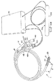
図1は、本発明を実施するための最良の形態である能動チューブシステムの全体の構成図である。能動チューブシステム1は、屈曲機構21を内蔵した先端部2を備えた能動チューブ3と、能動チューブ3の屈曲機構21を制御するコントロールボックス10とからなる。コントロールボックス10には、手指で操作可能なコントロールスティックなどの制御入力部10aを外部に接続している。
能動チューブ3は、屈曲機構21を内蔵して複数のリング状の錘22を装着した先端部2と、先端部2の後端に接合する本体チューブ4とからなる。
本体チューブ4の後端部41には、本体チューブ4の中心軸から後方に傾斜して、小腸などの腸に溜まった内容物を吸引するために腸内容吸引管として用いられるワーキングチャネル4Aと、配線用チャネル4Bと、本体チューブ4の先端に装着しているバルーンに空気や液体を送り込むためのバルーン膨らまし用チャネル4Cと、本体チューブ4の先端付近の通気孔に導通するベント用チャネル4Dとが接続している。
(First form)
FIG. 1 is an overall configuration diagram of an active tube system which is the best mode for carrying out the present invention. The
The
In the
最初に、能動チューブ3について説明する。
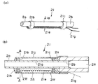
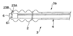
図2は能動チューブの構造を示す図であり、(a)は能動チューブ3の先端部2の分解斜視図であり、(b)は能動チューブ3の先端の断面図である。能動チューブ3の先端側には、チューブの長手方向に屈曲機構21を内蔵した先端部2を備えている。図2(a)に示すように、能動チューブ3の先端部2は、屈曲機構21を、複数のくびれ部分にリング状の錘22を内蔵した外皮用チューブ25の後方から挿入し、前方から先端チップ23が装着される構成を有している。
First, the
2A and 2B are diagrams showing the structure of the active tube, where FIG. 2A is an exploded perspective view of the
ここで、後述する図3(a)(b)で説明するように、ワーキングチャネル用チューブ21aが、屈曲機構21の所定の孔に挿通してある。
先端部2の先端側には、ワーキングチャネル用チューブ21aを延設して先端接合フランジ2aを形成する。先端接合フランジ2aの外周は、先端チップ23の後端接合フランジ23aに接合する。この先端チップ23は、円筒状の後端接合フランジ23aと同一径の貫通穴を形成し、先端側が滑らかな形状になっている。
Here, as will be described later with reference to FIGS. 3A and 3B, the working
On the distal end side of the
また、先端部2の後端側には、ワーキングチャネル用チューブ21aが延設されており、後端接合フランジ2bを形成する。この後端接合フランジ2bの外周には、ジョイント用チューブ24を接合している。そして、ジョイント用チューブ24の外周に本体チューブ4を接合する。これにより、先端部2が本体チューブ4と接合される。
Further, a working
図2(b)に示すように、屈曲機構21の外周には、所定の間隔を開けて複数のリング状の錘22が嵌着されている。すなわち、この錘22は、上記ワーキングチャネル用チューブ21aと屈曲機構21を構成するSMAコイルとを一体としてその外周に装着されている。さらに、屈曲機構21の外周側には、複数のリング状の錘22に亙るように外皮用チューブ25が部分的に装着されている。外皮用チューブ25の先端側は、先端チップ23の後端接合フランジ23aの外周面と接合し、外皮用チューブ25の後端側は、ジョイント用チューブ24の外周面と接合する。上記リング状の錘22は例えばステンレス製であり、外皮用チューブ25は例えば薄肉シリコーンチューブなどを用いることができる。
As shown in FIG. 2B, a plurality of ring-shaped
次に、屈曲機構21の一例を説明する。図3及び図4は、屈曲機構21の構造を示す図である。
図3において、(a)は屈曲機構21の一部斜視図であり、(b)は屈曲機構21の断面図である。図3(a)に示すように、前リンク21bおよび後リンク21cで、ワーキングチャネル用チューブ21aが支持されている。すなわち、ワーキングチャネル用チューブ21aの先端側は、前リンク21bの大径孔21dに挿通され、挿通された前端部分で先端接合フランジ2aを形成する。また、ワーキングチャネル用チューブ21aの後端側は、後リンク21cの大径孔21dに挿通され、挿通された後端部分は後端接合フランジ2bを形成し、ジョイント用チューブ24と接合する。
Next, an example of the
3A is a partial perspective view of the
図3(b)に示すように、螺旋状に形成したSMAコイル21eが、後リンク21cの第一の小径孔21fに挿通され、前リンク21bの第一の小径孔21fまで必要に応じて撓みを持たせて配線される。また、SMAコイル21eは、前リンク21bの第一の小径孔21fに挿通されて折り返され、前リンク21bの第二の小径孔21fに挿通されて、対向する後リンク21cの第二の小径孔21fに挿通される。そして、SMAコイル21eの両端は、別の材質、例えば絶縁被覆付銅線でなる配線21gに半田などで接続されている。ここで、前リンク21bおよび後リンク21cは、何れも同じ形状であり、例えば光造形法により紫外線を受光して固くなる紫外線感光樹脂で成形することができる。
As shown in FIG. 3B, the spirally formed
また、ワーキングチャネル用チューブ21aには、絶縁性の外皮21jが被覆されている。外皮21jの両端は、前リンク21bおよび後リンク21cの外周と固着される。さらに、外皮21jの後部は、後リンク21cとワーキングチャネル用チューブ21aとを支持固着する接着剤21iに当接するように、ジョイント用チューブ24の先端側外周に被覆されている。
The working
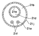
図4は、図3(b)のA−A線に沿う断面図である。図示するように、前リンク21bおよび後リンク21cは、ワーキングチャネル用チューブ21aを挿通する大径孔21dが一つと、SMAで作製したSMAコイル21eを挿通する小径孔21fが二つ穿設されている。
FIG. 4 is a cross-sectional view taken along the line AA in FIG. As shown in the figure, the front link 21b and the
上記屈曲機構21において、SMAコイル21eの図の上下方向の空間2Aが、前リンク21bおよび後リンク21cで囲繞されている。すなわち、空間2Aは空気層となる。このため、外皮21jやワーキングチャネル用チューブ21aや外皮用チューブ25を屈曲しやすくし、先端部2を放熱し易い構造とし熱がこもり難い構造としている。さらに、SMAコイル21eの変態点温度が低い材料を使用することが好適である。例えば、変態点温度を60℃とすればよい。これにより、発生する熱量そのものを抑え、かつ、SMAコイル21eの周囲の空間2Aに、熱伝導させる空気層を設けることにより、通電による屈曲機構21の温度上昇を抑えることができる。
In the
なお、図3および図4に示した屈曲機構21は、一本のSMAコイル21eを前リンク21b側で一回だけ折り返した構成であるが、別にSMAコイル21eの配線の仕方はこれに限定されるものではない。例えば、一本のSMA21eを前リンク21bと後リンク21cでそれぞれ複数回折り返して配線してもよい。すなわち、前リンク21bおよび後リンク21cにそれぞれ穿設した各小径孔にSMAコイル21eを挿通して、複数回折り返してもよい。この構成により、先端部2を屈曲し易くすることができる。このとき、一本のSMAコイル21eの両端は、何れも後リンク21cの本体チューブ4側に出るようにするのが好ましい。
さらには、複数本のSMAコイル21eを対称的に配線してもよい。すなわち、屈曲機構21の前後方向を法線方向とする断面(図3(b)のA−A線の断面)において、各SMAコイル21e同士が、屈曲機構21の中心軸に対して互いに対称的になるように配線してもよい。例えば3本のSMAコイル21eを配線する場合には、各SMAコイル21e同士が屈曲機構21の中心軸に対して120度をなすように配線してもよい。この場合には、各SMAコイル21eによる各屈曲方向を相互に連関させて先端部2をあらゆる方向に屈曲させることができる。このとき各SMAコイル21eは前リンク21bおよび後リンク21c間で一回の折り返しでもよいし、複数回折り返してもよい。
The
Furthermore, a plurality of
次に、本体チューブ4について説明する。図5は本体チューブ4の後端部41の部分断面図、図6は図1のB−B線に沿う断面図である。本体チューブ4は、長手方向に亙って、ワーキングチャネル4Aと、配線21gを挿通する配線用チャネル4Bとを少なくとも有する。また、使用用途に応じて、例えば第一の形態にあっては、ワーキングチャネル4Aおよび配線用チャネルの他に、その他のチャネルとして一または複数の管を成形したマルチチャネル型のものでもよい。
Next, the
図6に示すように、能動チューブ3が腸閉塞治療用能動チューブの場合には、本体チューブ4の大部分は、所定の形状のワーキングチャネル4Aで占められており、ワーキングチャネル4Aと本体チューブ4の外周との間に、ワーキングチャネル4Aの径より小さいベント用チャネル4Dが成形され、ベント用チャネル4Dの両端にベント用チャネル4Dより径の小さい配線用チャネル4Bおよびバルーン膨らまし用チャネル4Cが成形されている。なお、本体チューブ4は可撓性を有する素材で成形し、その材料として例えば、シリコーンが好適である。
As shown in FIG. 6, when the
ここで、配線用チャネル4B,バルーン膨らまし用チャネル4Cおよびベント用チャネル4Dの各後端部41には、各々専用のコネクター4B1,4C1,4D1が装着されている。ワーキングチャネル4Aの終端にも蓋やコネクター等が装着されていてもよい。例えば、配線21gを挿通する配線用チャネル4Bのコネクター4B1としては、一対の配線21gに対応するモノラルジャックや二対の配線21gに対応するステレオジャックなどを挙げることができる。
Here, dedicated connectors 4B1, 4C1, and 4D1 are attached to the
次に、本体チューブ4の先端側に装着されているバルーンについて説明する。
図7は本体チューブ4の先端側に装着されているバルーンの構造の箇所の概略断面図であり、図8はそのバルーンの側面図である。本体チューブ4の先端側の所定の位置には、例えば弾性の薄膜からなるバルーン42が装着されている。バルーン42の前後部分は、本体チューブ4の外周に接着剤42aなどで固着されている。本体チューブ4において、バルーン42で被覆されている箇所には、例えば3つの注入口42bが穿設されている(図8参照)。これにより、バルーン膨らまし用チャネル4Cに通された空気などの気体や水などの液体は、図7に矢印で示すように、注入口42bを通過してバルーン42を膨張させる。なおバルーン42に使用する円筒の薄膜には、例えばシリコーンゴムを用いることができる。
Next, the balloon attached to the distal end side of the
FIG. 7 is a schematic sectional view of a portion of the structure of the balloon mounted on the distal end side of the
以下、能動チューブ3の製造方法を説明する。
先ず、先端部2の屈曲機構21を組み立てる。すなわち、図3(a)に示すように、ワーキングチャネル用チューブ21aの先端側を延設するように前リンク21bの大径孔21dに挿通する。また、ワーキングチャネル用チューブ21aの後端側を延設するように後リンク21cを大孔径21dに挿通する。必要に応じて、前リンク21bおよび後リンク21cとワーキングチャネル用チューブ21aの外周面とは接着剤などで仮止めする。また、SMAでSMAコイル21eを作製する。SMAコイル21eは、例えば、素線径50〜100μm、外径200〜300μmのものを用いる。そして、後リンク21cの第一の小径孔21fにSMAコイル21eの一端を挿通し、前リンク21bの第一の小径孔21fに挿通する。その後、前リンク21bの第一の小径孔21fに挿通したSMAコイル21eの先端を折り返して、前リンク21bの第二の小径孔21fに挿通し、後リンク21cの第二の小径孔21fに挿通する。SMAコイル21eの両端、すなわち、後リンク21c側の両端を、必要に応じて別の配線と接続する。
Hereinafter, a method for manufacturing the
First, the
そして、外皮21jをワーキングチャネル用チューブ21aの長手方向に沿って被覆し、前リンク21bの外周と外皮21jの先端側内周面とを接合して前リンク21bの前側面に絶縁性の接着剤21hを盛る。接着剤21hでワーキングチャネル用チューブ21a,前リンク21b,SMAコイル21eおよび外皮21j同士を固着する。同様にして、後リンク21cの外周と外皮21jの後端側内周面とを接合して後リンク21cの後側面に絶縁性の接着剤21iを盛る。接着剤21iでワーキングチャネル用チューブ21a,後リンク21c,SMAコイル21e(または配線21g)および外皮21j同士を固着する。接着剤21h,21iとして、例えばシリコーンを用いることができる。
続いて、屈曲機構21の後端接合フランジ2bの外側に、ジョイント用チューブ24を接続して、後端接合フランジ2bとジョイント用チューブ24の前側の内周面とを絶縁性の接着剤で固定し、これで屈曲機構21が組み立てられる。
Then, the
Subsequently, the
次に、図2(a)に示すように、組み立てた屈曲機構21を、外皮用チューブ25の後方から挿入し、屈曲機構21に先端チップ23を装着する。すなわち、先端チップ23の後端接合フランジ23aの内周面と、ワーキングチャネル用チューブ21aの先端接合フランジ2aの端面とを絶縁性の接着剤で接着する。これで、能動チューブ3の先端部2が作製される。先端部2の大きさは、例えば、外径数mm、長さ数十mmである。
そして、能動チューブ3の先端部2のSMAコイル21eの両端を、本体チューブ4の配線用チャネル4Bに挿通されている配線21gと半田などで結合させる。なお、SMAコイル21eの両端に別の配線を必要に応じて接続した場合には、この別の配線を配線21gと結合させる。本体チューブ4と先端部2とを連通させて、ジョイント用チューブ24の後端端面と本体チューブ4の前側の内周面とを絶縁性の接着剤で接着することにより能動チューブ3が完成する。
Next, as shown in FIG. 2A, the assembled
Then, both ends of the
次に、コントロールボックス10を説明する。
図9はコントロールボックス10の機能ブロック図である。コントロールボックス10は、能動チューブ3の先端部2に内蔵されている屈曲機構21を制御する。この制御により先端部2を屈曲させる。例えば、図9に示すように、コントロールボックス10は、ポテンショメータを内蔵したコントロールスティックなどからなる制御入力部10aと、制御入力部10aからの入力信号を受けて屈曲機構21に対して制御信号を出力する制御部10bと、制御部10bに対して電源供給を行う電源部10cとを有する。ここで、制御入力部10aは、例えば、手のひらで容易に掴めるようにグリップを形成してあるスティック10Aに、手指でレバー10Bを移動することで入力可能なスライド式操作機構を備えたコントロールスティックである。また、制御部10bはマイクロコンピュータなどで構成され、電源部10cは乾電池などで構成される。
Next, the
FIG. 9 is a functional block diagram of the
SMAコイル21eへの通電は、その一端に接続された直流電源10dからの通電量を制御素子10eにより制御する。この直流電源10dとしては乾電池、制御素子10eとしてはパワートランジスターを用いることができる。
なお、コントロールボックス10の制御入力部10aの代わりに、コントロールボックス10に内蔵された入力部10fを用いてもよい。
特に、屈曲機構21に対する制御方式として、パルス幅変調(PWM:pulse Width Modulation)方式を用いることができる。PWM方式を採用することにより、SMAコイル21eへの通電時間と通電していない時間とを繰り返して、SMAコイル21eへの通電による加熱時と放熱時とを繰り返す。これにより、SMAコイル21eの温度を抑制し、屈曲機構21、ひいては先端部2そのものの温度を抑制できる。また、通電の時間サイクルのデューティ比を変えることで、一サイクルでの通電量を変化させて屈曲機構21の屈曲角を制御することができる。
The energization to the
Instead of the
In particular, a pulse width modulation (PWM) method can be used as a control method for the
以上のように構成された能動チューブシステム1は次のように動作する。
図10は、コントロールボックス10の制御入力部10aとしてのコントロールスティックのレバー10Bを操作して、能動チューブ3の先端部2の屈曲状態を示した断面図である。コントロールスティックのレバー10Bを操作して、コントロールボックス10の制御部10bに入力し、その入力に応じて制御素子10eを制御する。制御素子10eは、SMAコイル21eへの一サイクルでの通電量を変化させる。これにより、SMAコイル21eの通電量に対応して、屈曲機構21が作用し先端部21の屈曲角が一定に保たれる。
The
FIG. 10 is a cross-sectional view showing a bent state of the
ここで、SMAコイル21eは通電により発熱するが、図10に示すように、屈曲機構21は、ワーキングチャネル用チューブ21aと外皮21jと、前後を前リンク21bおよび後リンク21cで囲繞された空間2A内が空気で占められ、さらに、外皮21jと外皮用チューブ25との間の空間2Bにも空気が占めらた、すなわち空間2A、2Bからなる空気層を有している。したがって、先端部2の内部に空間2A, 2Bを持たせて、外皮21jやワーキングチャネル用チューブ21aや外皮用チューブ25を屈曲しやすくし、先端部2を放熱し易い構造としている。また、SMAコイル21eの材料を変態点が低いもの、例えば60℃のものを用いる。これにより、発生する熱量そのものを抑え、かつ、空気層による放熱効果により、SMAコイル21eへの通電による屈曲機構21の温度上昇を低下させることができる。
Here, the
(第二の形態)
次に、本発明の第二の実施形態に係る能動チューブシステムについて説明する。
図11は、第二の形態に係る能動チューブシステムの概略図である。第二の形態に係る能動チューブシステム1aは、能動チューブ3aと表示装置3Aからなる。能動チューブ3aは、第一の形態に係る能動チューブ3のワーキングチャネル用チューブ21aに、内視鏡5を、本体チューブ4のワーキングチャネル4Aから挿入したものである。この第二の形態においては、内視鏡5の先端側は能動チューブ3aの先端部2に固着されない。すなわち、内視鏡5は、本体チューブ4を介して先端部2に挿脱できるようにしたものである。
これにより、内視鏡5を本体チューブ4を介して先端部2に挿入し、必要に応じて内視鏡5のみを抜き取り、薬剤を挿入したり先端部2から内容物を吸い出したりすることができる。また、内視鏡5を必要に応じて洗浄などの処理を行い再利用することができる。
(Second form)
Next, an active tube system according to a second embodiment of the present invention will be described.
FIG. 11 is a schematic view of an active tube system according to the second embodiment. The active tube system 1a according to the second embodiment includes an active tube 3a and a
Thereby, the
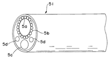
図12は、図11の内視鏡5とは別の内視鏡の一例を示す概略斜視図である。図12に示した内視鏡51の前側面には、光ファイバーまたはCCD(Charge Coupled Device)のような撮像素子などからなる画像入力部5aと、画像入力部5aの前方を照らす複数の照明用ライトガイド5bとを備える。また、内視鏡51には別途作業用のチャネル5cが備わっていてもよい。また、内視鏡51には画像入力部5aの画面を洗浄するために生理食塩水を導入する導入管が備わっており、内視鏡51の前側面には導入管の先端に当る噴射口5dが備わっていてもよい。ここで、照明用ライトガイド5bの代わりにLED(Light Emitting Diode)でもよい。
12 is a schematic perspective view showing an example of an endoscope different from the
(第三の形態)
次に、本発明の第三の実施形態に係る能動チューブシステムについて説明する。
図13は、第三の形態に係る能動チューブの概略図である。第三の形態に係る能動チューブ3bは、第一の形態に係る能動チューブ3のワーキングチャネル用チューブ21aに,内視鏡6を挿通し、内視鏡6の先端を能動チューブ3bの先端チップ23Aに固着したものである。先端チップ23Aの内周には、内視鏡6と係合する係合部を有する。この係合部は、例えば、先端チップ23Aの先端を軸側に鍔23Bを延設して成形される。先端チップ23Aの係合部は、内視鏡6の係合部、例えば凹部61と係合して、内視鏡6を先端チップ23Aから脱離できないようにする。
(Third form)
Next, an active tube system according to a third embodiment of the present invention will be described.
FIG. 13 is a schematic view of an active tube according to a third embodiment. The
図14は、内視鏡6の一例を示す概略斜視図である。内視鏡6の前側面には、CCDのような撮像装置などからなる画像入力部6aと、画像入力部6aの前方を照らす複数のLED6bとを備える。また、内視鏡6には別途作業用のチャネル(図示せず)が備わっていてもよく、画像入力部6aの画面を洗浄するために生理食塩水を導入する導入管が備わって、内視鏡6の前側面には導入管の先端に当る噴射口6dが備わっていてもよい。
FIG. 14 is a schematic perspective view showing an example of the
ここで、画像入力部6aはCCDではなく、第二の形態のように、光ファイバーを用いて、外部に画像を取り出してもよい。また、LED6bの代わりに第二の形態のように、照明用ライトガイドを有しており、外部からの光を照明用ライトガイドが導いて画像入力部6a前方を照らすようにしてもよい。なお、内視鏡6を先端チップ23Aで固定する際には、内視鏡6および先端チップ23Aに係合部を設けたが、接着剤などで固着してもよい。
以上の第二の形態および第三の形態における内視鏡としては、例えば、直径3〜10mmの径のものや、それより細い、例えば2.5mmの極細のものが挙げられる。
Here, the image input unit 6a may take out an image to the outside using an optical fiber instead of a CCD as in the second embodiment. Further, instead of the
As an endoscope in the above 2nd form and the 3rd form, a diameter of 3-10 mm in diameter is mentioned, for example, and it is thinner than that, for example, a very thin thing of 2.5 mm, for example.
以下、能動チューブシステムの使用形態について説明する。ここでは、特に腸閉塞治療に用いる場合を念頭において説明する。
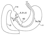
図15は、能動チューブシステムの第一の使用形態を示す概念図である。図では、鼻腔または口腔から能動チューブ3a,3bを挿入して体内に推し進められて胃11の出口である幽門部11aを通過させる場合を示している。この幽門部11aは、非常に小さく挿入困難な場所である。内視鏡を挿入した能動チューブ3a,3bの場合には、術者が内視鏡5, 51, 6の先端の画像入力部5a,6aからの画像を表示装置3Aなどで観察しながら、コントロールボックス10の制御入力部10aを操作する。制御入力部10aの操作により、能動チューブ3の先端部2が屈曲する。
例えば、コントロールスティックのレバー10Bを移動させることで、図に矢印で示すように、能動チューブ3の先端部2の屈曲角を自由に変えることができる。そして、能動チューブ3の先端部2を屈曲させて、先端部2を幽門部11aに向けて能動チューブ3a,3bを押し進め、十二指腸12内に挿入することが容易になる。
Hereinafter, usage forms of the active tube system will be described. Here, the case where it uses especially for intestinal obstruction treatment is explained in mind.
FIG. 15 is a conceptual diagram showing a first usage pattern of the active tube system. The figure shows a case where the
For example, by moving the lever 10B of the control stick, the bending angle of the
図16は、能動チューブシステムの第二の使用形態を示す概念図である。同図は、能動チューブ3a,3bを胃11からさらに腸内に挿入された状態を示している。能動チューブ3a,3bの先端部2の後側で本体チューブ4の前側に装着されているバルーン42を膨らまし、腸壁13aにバルーン42を接触させる。このバルーン42が腸壁13aに接触することで、能動チューブ3a,3bの先端側が固定される。
この状態で、第一の使用形態で説明したように、術者が内視鏡5, 51, 6の先端の画像入力部5a,6aからの画像を表示装置3Aなどで観察しながら、コントロールボックス10の制御入力部10aを操作する。このため、制御入力部10aの操作により、能動チューブ3a,3bの先端部2が屈曲する。例えば、コントロールスティックのレバー10Bを移動させることで、矢印で示すように、能動チューブ3の先端部2の屈曲角を自由に変えることができる。これで、術者は腸壁13aを意のままに観察できる。また、腸のぜん動運動により、バルーン42を腸内の前方側に進ませることができる。
このように、能動チューブ3a,3bは、バルーン42を装着した本体チューブ4と、屈曲機構21を内蔵した先端部2とを接合するとともに、光ファイバーやCCDなどの撮像素子からなる画像入力部5a,6aを先端部2に内蔵しているので、腸内観察用の内視鏡として用いることができる。
FIG. 16 is a conceptual diagram showing a second usage pattern of the active tube system. This figure shows a state in which the
In this state, as described in the first usage pattern, the operator observes the images from the image input units 5a and 6a at the distal ends of the
As described above, the
なお、第一の使用形態および第二の使用形態においては、内視鏡を挿入してある能動チューブ3a,3bを前提に説明したものの、内視鏡が挿入されていない能動チューブ3においても、X線透過画像を併用することで同様に使用することもできる。
In the first usage pattern and the second usage pattern, the
また、以上の第一乃至第三の形態においては、先端部2内の屈曲機構21は一本のSMAコイル21eからなるが、屈曲機構21の断面に対して複数本のSMAコイル21eを対称的に配置して、各SMAコイル21eへの通電加熱を行うことで、全方向に先端部2を屈曲させることができる。この場合には、制御入力部10aは、例えば、SMAコイル21eの本数と同数のスライド式制御機構をコントロールスティックに設けることで実現できる。
In the first to third embodiments described above, the
(第四の形態)
次に、第四の形態について図16を参照して説明する。
第四の形態は、第二の形態における能動チューブ3aや第三の形態における能動チューブ3bの先端部2に複数の錘22を設けないものである。すなわち、能動チューブ3は、屈曲機構21を内蔵した先端部2と、先端部2の後端に接合する本体チューブ4とからなっており、内視鏡5,51,6を、本体チューブ4のワーキングチャネル4Aおよび先端部2のワーキングチャネル用チューブ21aに挿入してあるものである。屈曲機構21や本体チューブ4の構成は、他の形態と同様である。
(Fourth form)
Next, a fourth embodiment will be described with reference to FIG.
In the fourth embodiment, the plurality of
次のようにイレウス用の能動カテーテルを作製した。
素線径50〜100μmのニッケル・チタン系SMAを用いて、外径200〜300μmのSMAコイル21eを作製して屈曲機構21を組み立て、先端部2を作製した。このとき、先端部2の長さは約40mm、外径6mmであった。そして、本体チューブ4に先端部2を接合した。屈曲機構21は、ピーク電圧16.5V、パルス周期86.2Hzのパルス電圧で駆動して、デューティ比を変化させて先端部2を屈曲させた。
An active catheter for ileus was prepared as follows.
Using a nickel / titanium SMA having a strand diameter of 50 to 100 μm, an
図17は、パルス電圧のデューティ比に対する先端部2の屈曲角を示す図である。屈曲角は、本体チューブ4の延長線と先端部21とのなす角である。各デューティ比に対し、屈曲機構21が作動し先端部2が屈曲するまでの時間は一秒以内であった。また、コントロールスティックのレバー10Bを元に戻すことで、先端部2は、本体チューブ4の延長線上に位置する。
図17から分かるように、デューティ比が40%で、最大110°まで屈曲できた。このとき曲率半径は約20mmであった。また、本体チューブ4およびワーキングチャネル用チューブ21aに、直径1.14mmのガイドワイヤーを通したままでも、先端部2を屈曲できることを確認した。
FIG. 17 is a diagram showing the bending angle of the
As can be seen from FIG. 17, the duty ratio was 40% and the bending could be performed up to 110 °. At this time, the radius of curvature was about 20 mm. Further, it was confirmed that the
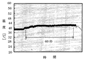
図18は、温度26℃の大気中における能動チューブ3の先端部の表面温度の経過時間を示す図である。所定のデューティ比に固定して屈曲角が30°, 45°, 60°となるようにSMAコイル21eに通電させて、先端部2の外皮用チューブ25の表面温度を熱電対で測定したものである。熱電対は、SMAコイル21eの輻射熱を直接受ける箇所とし、具体的には錘22の間の外皮用チューブ25に当接させた。図から明らかなように、通電開始から表面温度が41℃を越える時間は、屈曲角が30°、45°、60°の場合に、それぞれ、60秒、40秒、25秒であることが分かる。
FIG. 18 is a diagram illustrating the elapsed time of the surface temperature of the tip of the
さらに、能動チューブ3を腸閉塞治療用能動チューブとして使用する場合を想定し、すなわち、使用される箇所が胃や腸内であり食物などの残渣などがあることを想定して、水温38℃の水に浸した状態での能動チューブの表皮温度も確認した。
図19〜図21は、水温38℃の水に浸した状態で、先端部2の屈曲角として、それぞれ、30°、45°、60°に屈曲させたときの先端部2の表面温度の経過時間を示す図である。これらの図から判るように、屈曲角30°では表面温度は約41℃で一定し、屈曲角45°では表面温度は約42℃で一定する。また、屈曲角60°では、一分以上屈曲状態を保っても約44℃まで上昇しない。これは、能動チューブ3の先端部2の最表面には、大気より熱伝導性の良い水が存在することで、熱効率が向上したためと考えられる。これにより、屈曲角30°においては、表面温度は、約41℃以下となり、十分に治療用に使用可能であることが分かった。
Further, assuming that the
19 to 21 show the progress of the surface temperature of the
以上説明した各種の実施の形態は本発明を実施するための一例に過ぎず、本発明は特許請求の範囲に記載した範囲内で種々の変更が可能であり、これらも本発明の範囲に含まれることはいうまでもない。 The various embodiments described above are merely examples for carrying out the present invention, and the present invention can be variously modified within the scope of the claims, and these are also included in the scope of the present invention. Needless to say.
1,1a 能動チューブシステム
2 先端部
2A,2B 空間
2a 先端接合フランジ
2b,23a 後端接合フランジ
3, 3a,3b 能動チューブ
3A 表示装置
4 本体チューブ
4A ワーキングチャネル
4B 配線用チャネル
4C バルーン膨らまし用チャネル
4D ベント用チャネル
4B1, 4C1, 4D1 コネクター
5, 51, 6 内視鏡
5a,6a 画像入力部
5b 照明用ライトガイド
5c チャネル
5d,6d 噴射口
6b LED
10 コントロールボックス
10A スティック
10B レバー
10a 制御入力部
10b 制御部
10c 電源部
10d 直流電源
10e 制御素子
10f 入力部
11 胃
11a 幽門部
12 十二指腸
13a 腸壁
21 屈曲機構
21a ワーキングチャネル用チューブ
21b 前リンク
21c 後リンク
21d 大径孔
21e SMAコイル
21f 小径孔
21g 配線
21h,21i 接着剤
21j 外皮
22 錘
23,23A 先端チップ
23B 鍔
24 ジョイント用チューブ
25 外皮用チューブ
41 後端部
42 バルーン
42a 接着剤
42b 注入口
61 凹部
DESCRIPTION OF
DESCRIPTION OF
Claims (14)
上記ワーキングチャネル用チューブに沿って配設したSMAコイルと、
上記ワーキングチャネル用チューブと上記SMAコイルとを一体としてその外周に装着した一以上の錘と、
上記ワーキングチャネル用チューブと上記SMAコイルとを含んで上記錘の外周を被覆した外皮用チューブと、を備えたことを特徴とする能動チューブ。 A working channel tube that uses the interior as a working channel;
An SMA coil disposed along the working channel tube;
One or more weights integrally attached to the outer periphery of the working channel tube and the SMA coil;
An active tube comprising: the working channel tube and the SMA coil; and an outer tube covering the outer periphery of the weight.
上記本体チューブに連通するワーキングチャネル用チューブと、
該ワーキングチャネル用チューブを支持して該ワーキングチャネル用チューブを屈曲させる屈曲機構と、
上記屈曲機構の外周に装着される一または複数の錘と、
上記錘とともに上記屈曲機構の外周を被覆する外皮用チューブと、を上記先端部に備えており、
上記屈曲機構は、上記ワーキングチャネル用チューブの長手方向に沿って配設したSMAコイルを含むことを特徴とする能動チューブ。 In an active tube comprising a tip and a body tube joined to the tip,
A working channel tube communicating with the main body tube;
A bending mechanism for supporting the working channel tube and bending the working channel tube;
One or more weights mounted on the outer periphery of the bending mechanism;
An outer tube for covering the outer periphery of the bending mechanism together with the weight, and the tip portion,
The active tube, wherein the bending mechanism includes an SMA coil disposed along a longitudinal direction of the working channel tube.
前記本体チューブには、該本体チューブの軸に沿って、本体チューブと上記薄膜との空間に気体または液体を送るためのバルーン膨らまし用チャネルが設けられて、上記薄膜が膨張してバルーンを構成することを特徴とする、請求項2に記載の能動チューブ。 On the distal end side of the main body tube, a cylindrical thin film is coated on the outer periphery of the main body tube so as to be expandable,
The main body tube is provided with a balloon inflating channel for sending gas or liquid to the space between the main body tube and the thin film along the axis of the main body tube, and the thin film expands to form a balloon. The active tube according to claim 2, wherein:
前記ワーキングチャネル用チューブに間隔を開けて装着される一対のリンクと、
該一対のリンクに接合して前記ワーキングチャネル用チューブを被覆する外皮と、を有しており、
前記一対のリンクと前記ワーキングチャネル用チューブの外周面とで空気層を画成して、前記SMAコイルが、前記一対のリンクの各小径孔に挿通されて、上記空気層に架線されていることを特徴とする、請求項2に記載の能動チューブ。 The bending mechanism is
A pair of links attached to the working channel tube at an interval;
An outer skin that joins the pair of links and covers the working channel tube;
Defining an air layer between the outer peripheral surface of the pair of link said working channel tube, the SMA coil, wherein are inserted into the small diameter hole of a pair of links, are overhead wire to the air layer Rukoto The active tube according to claim 2, wherein:
内視鏡を備えており、
上記先端部は、上記本体チューブに連通するワーキングチャネル用チューブと、該ワーキングチャネル用チューブを支持して該ワーキングチャネル用チューブを屈曲させる屈曲機構と、該屈曲機構の外周を被覆する外皮用チューブと、を備え、
上記屈曲機構は、上記ワーキングチャネル用チューブの長手方向に沿って配設したSMAコイルと、上記ワーキングチャネル用チューブに間隔を開けて装着される一対のリンクと、該一対のリンクに接合して上記ワーキングチャネル用チューブを被覆する外皮と、を有しており、
上記一対のリンクと上記ワーキングチャネル用チューブの外周面とで空気層を画成し、上記SMAコイルが上記一対のリンクの各小径孔に挿通されて上記空気層に架線され、
上記SMAコイルは、後リンクの第一の小径孔および前リンクの第一の小径孔に挿通され、上記前リンクの前端で折り返して上記前リンクの第二の小径孔および上記後リンクの第二の小径孔に挿通して架線されており、
上記本体チューブの先端には、上記本体チューブの外周に円筒薄膜が膨張可能に被覆されており、上記本体チューブには、該本体チューブの軸に沿って、前記本体チューブと上記薄膜との空間に空気または液体を送るためのバルーン膨らまし用チャネルが設けられて、上記薄膜が膨張してバルーンを構成することを特徴とする能動チューブ。 In an active tube comprising a tip and a body tube joined to the tip,
Equipped with an endoscope,
The distal end portion includes a working channel tube communicating with the main body tube, a bending mechanism that supports the working channel tube and bends the working channel tube, and a skin tube that covers the outer periphery of the bending mechanism; With
The bending mechanism includes an SMA coil disposed along a longitudinal direction of the working channel tube, a pair of links attached to the working channel tube with a space therebetween, and a pair of links joined to the pair of links. An outer skin covering the working channel tube;
An air layer is defined by the pair of links and the outer peripheral surface of the working channel tube, and the SMA coil is inserted into each small-diameter hole of the pair of links and is wired to the air layer.
The SMA coil is inserted into the first small-diameter hole of the rear link and the first small-diameter hole of the front link, and is folded back at the front end of the front link so as to return to the second small-diameter hole of the front link and the second small-diameter hole of the rear link. Is inserted through the small-diameter hole of
A cylindrical thin film is coated on the outer periphery of the main body tube at the tip of the main body tube so as to be expandable, and the main body tube is provided in the space between the main body tube and the thin film along the axis of the main body tube. balloons inflated channel for delivering air or liquid is provided, the active tube you characterized that you configure the balloon the thin film is inflated.
該能動チューブの屈曲機構を制御するコントロールボックスと、
該コントロールボックスに対して上記屈曲機構への制御情報を入力する制御入力部とからなることを特徴とする能動チューブシステム。 Active tube according to any of claims 2 to 12,
A control box for controlling the bending mechanism of the active tube;
An active tube system comprising: a control input unit for inputting control information to the bending mechanism to the control box.
Priority Applications (5)
| Application Number | Priority Date | Filing Date | Title |
|---|---|---|---|
| JP2003415402A JP3852033B2 (en) | 2003-12-12 | 2003-12-12 | Active tube and active tube system |
| US10/582,355 US20070083084A1 (en) | 2003-12-12 | 2004-12-10 | Active tube and active tube system |
| PCT/JP2004/018855 WO2005055818A1 (en) | 2003-12-12 | 2004-12-10 | Active tube and active tube system |
| CNB2004800369716A CN100399977C (en) | 2003-12-12 | 2004-12-10 | Active tube and active tube system |
| EP04807213A EP1695655A4 (en) | 2003-12-12 | 2004-12-10 | Active tube and active tube system |
Applications Claiming Priority (1)
| Application Number | Priority Date | Filing Date | Title |
|---|---|---|---|
| JP2003415402A JP3852033B2 (en) | 2003-12-12 | 2003-12-12 | Active tube and active tube system |
Publications (2)
| Publication Number | Publication Date |
|---|---|
| JP2005168910A JP2005168910A (en) | 2005-06-30 |
| JP3852033B2 true JP3852033B2 (en) | 2006-11-29 |
Family
ID=34675130
Family Applications (1)
| Application Number | Title | Priority Date | Filing Date |
|---|---|---|---|
| JP2003415402A Expired - Fee Related JP3852033B2 (en) | 2003-12-12 | 2003-12-12 | Active tube and active tube system |
Country Status (5)
| Country | Link |
|---|---|
| US (1) | US20070083084A1 (en) |
| EP (1) | EP1695655A4 (en) |
| JP (1) | JP3852033B2 (en) |
| CN (1) | CN100399977C (en) |
| WO (1) | WO2005055818A1 (en) |
Families Citing this family (19)
| Publication number | Priority date | Publication date | Assignee | Title |
|---|---|---|---|---|
| JP4912705B2 (en) * | 2006-03-17 | 2012-04-11 | 日本コヴィディエン株式会社 | Medical tube assembly |
| US8123678B2 (en) * | 2006-04-07 | 2012-02-28 | The Regents Of The University Of Colorado | Endoscope apparatus, actuators, and methods therefor |
| JP5042656B2 (en) * | 2007-02-09 | 2012-10-03 | オリンパスメディカルシステムズ株式会社 | Imaging device |
| JP4946675B2 (en) * | 2007-07-05 | 2012-06-06 | コニカミノルタオプト株式会社 | Shape memory alloy drive device, imaging device using the same, and shape memory alloy drive method |
| US20090208143A1 (en) * | 2008-02-19 | 2009-08-20 | University Of Washington | Efficient automated urothelial imaging using an endoscope with tip bending |
| EP2668888B1 (en) * | 2011-04-08 | 2016-08-10 | Olympus Corporation | Endoscope |
| ITTO20130943A1 (en) | 2013-11-20 | 2015-05-21 | Fond Istituto Italiano Di Tecnologia | DISTAL SCANNING MODULE, IN PARTICULAR TO CHECK THE POINTING AND MOVEMENT OF AN OPTICAL DEVICE OF A MEDICAL DEVICE, AS A DIAGNOSTIC OR SURGICAL INSTRUMENT. |
| WO2015093398A1 (en) * | 2013-12-18 | 2015-06-25 | オリンパス株式会社 | Endoscope and endoscope system |
| CN104207749A (en) * | 2014-06-20 | 2014-12-17 | 乐虹信息科技(上海)有限公司 | Endoscope with controllable angle |
| WO2018204659A1 (en) * | 2017-05-03 | 2018-11-08 | Case Western Reserve University | Device for collecting a biological sample |
| WO2018232190A1 (en) * | 2017-06-14 | 2018-12-20 | The University Of Vermont And State Agricultural College | Peritoneal dialysis (pd) catheter weighted anchor |
| JP6803475B2 (en) * | 2017-08-23 | 2020-12-23 | オリンパス株式会社 | Insertion device and endoscope |
| CN107648727A (en) * | 2017-11-10 | 2018-02-02 | 安徽金思源生物科技有限公司 | A kind of throat feeding device |
| US11259858B1 (en) * | 2018-02-06 | 2022-03-01 | Jason RAHIMZADEH | Endoscopy tube and device for cryotherapy |
| US11724069B2 (en) | 2019-04-30 | 2023-08-15 | Covidien Lp | Catheter including contractible electroactive elements |
| CN110353610B (en) * | 2019-07-10 | 2021-05-25 | 乔建叶 | Endoscope system with crawling device |
| US11872359B2 (en) | 2020-11-12 | 2024-01-16 | Covidien Lp | Expandable-tip aspiration guide catheter |
| CN113543420B (en) * | 2021-09-14 | 2021-11-26 | 四川大学华西医院 | Illumination imaging illumination control method and device |
| EP4249984A1 (en) * | 2022-03-25 | 2023-09-27 | General Electric Company | Tool stabilization mechanism and related methods |
Family Cites Families (19)
| Publication number | Priority date | Publication date | Assignee | Title |
|---|---|---|---|---|
| US4516970A (en) * | 1982-09-13 | 1985-05-14 | Kaufman Jack W | Medical device |
| US5114402A (en) * | 1983-10-31 | 1992-05-19 | Catheter Research, Inc. | Spring-biased tip assembly |
| US4577621A (en) * | 1984-12-03 | 1986-03-25 | Patel Jayendrakumar I | Endoscope having novel proximate and distal portions |
| US4610673A (en) * | 1985-02-19 | 1986-09-09 | Superior Healthcare Group, Inc. | Gastroenteric feeding tube |
| US4930494A (en) * | 1988-03-09 | 1990-06-05 | Olympus Optical Co., Ltd. | Apparatus for bending an insertion section of an endoscope using a shape memory alloy |
| US4977886A (en) * | 1989-02-08 | 1990-12-18 | Olympus Optical Co., Ltd. | Position controlling apparatus |
| JP2843608B2 (en) * | 1989-08-31 | 1999-01-06 | オリンパス光学工業株式会社 | Bending operation device for tubular insert |
| JPH0531066A (en) * | 1991-08-01 | 1993-02-09 | Olympus Optical Co Ltd | Tubular insertion tool |
| US5354518A (en) * | 1993-02-11 | 1994-10-11 | Sherwood Medical Company | Method for manufacturing a fiberscopic catheter |
| US5645520A (en) * | 1994-10-12 | 1997-07-08 | Computer Motion, Inc. | Shape memory alloy actuated rod for endoscopic instruments |
| JP3713293B2 (en) * | 1994-11-10 | 2005-11-09 | オリンパス株式会社 | Electronic endoscope |
| US5810717A (en) * | 1995-09-22 | 1998-09-22 | Mitsubishi Cable Industries, Ltd. | Bending mechanism and stereoscope using same |
| JP3477570B2 (en) * | 1997-06-02 | 2003-12-10 | 正喜 江刺 | Active conduit and method of manufacturing the same |
| JP4096325B2 (en) * | 1998-12-14 | 2008-06-04 | 正喜 江刺 | Active capillary and method for manufacturing the same |
| US6425418B1 (en) * | 1999-10-27 | 2002-07-30 | Mitsubishi Cable Industries, Ltd. | Flexible tube and manufacturing method for the same |
| JP2002143312A (en) * | 2000-11-08 | 2002-05-21 | Sumitomo Bakelite Co Ltd | Catheter for medical treatment |
| US6764441B2 (en) * | 2001-09-17 | 2004-07-20 | Case Western Reserve University | Peristaltically self-propelled endoscopic device |
| CN1269620C (en) * | 2002-03-27 | 2006-08-16 | 辽宁工程技术大学 | Snake-shaped robot |
| US7001369B2 (en) * | 2003-03-27 | 2006-02-21 | Scimed Life Systems, Inc. | Medical device |
-
2003
- 2003-12-12 JP JP2003415402A patent/JP3852033B2/en not_active Expired - Fee Related
-
2004
- 2004-12-10 WO PCT/JP2004/018855 patent/WO2005055818A1/en active Application Filing
- 2004-12-10 EP EP04807213A patent/EP1695655A4/en not_active Withdrawn
- 2004-12-10 US US10/582,355 patent/US20070083084A1/en not_active Abandoned
- 2004-12-10 CN CNB2004800369716A patent/CN100399977C/en not_active Expired - Fee Related
Also Published As
| Publication number | Publication date |
|---|---|
| JP2005168910A (en) | 2005-06-30 |
| EP1695655A1 (en) | 2006-08-30 |
| CN100399977C (en) | 2008-07-09 |
| CN1893872A (en) | 2007-01-10 |
| US20070083084A1 (en) | 2007-04-12 |
| WO2005055818A1 (en) | 2005-06-23 |
| EP1695655A4 (en) | 2010-11-10 |
Similar Documents
| Publication | Publication Date | Title |
|---|---|---|
| JP3852033B2 (en) | Active tube and active tube system | |
| JP4676427B2 (en) | Disposable endoscopic imaging system | |
| JP4416990B2 (en) | System for operating a device in vivo | |
| JP4500015B2 (en) | Endoscope overtube | |
| US20080004606A1 (en) | Guide wire structure for insertion into an internal space | |
| JP2004181250A (en) | Medical device and method of moving medical appliance | |
| US20220304550A1 (en) | Systems and methods for modular endoscope | |
| JP2006505348A (en) | Endoscopic imaging system with removable deflection device | |
| JP3623894B2 (en) | In-vivo endoscope | |
| US20130053645A1 (en) | Disposable sheath with lighting | |
| Makishi et al. | Active bending electric endoscope using shape memory alloy coil actuators | |
| US20230380662A1 (en) | Systems and methods for responsive insertion and retraction of robotic endoscope | |
| JP4601943B2 (en) | Endoscope | |
| JP4527111B2 (en) | Guide wire structure for insertion into the interior space | |
| JP3944651B2 (en) | Active tube driving device and control stick for active tube driving device | |
| JP4650901B2 (en) | Guide wire with bent segments | |
| JPH08280603A (en) | Cover type endoscope | |
| WO2024059541A2 (en) | Systems and methods for medical device intubation | |
| WO2023055600A1 (en) | Systems and methods for configurable endoscope bending section | |
| WO2023129458A1 (en) | Systems and methods for robotic endoscope shaft | |
| JP2005319036A (en) | Endoscope and endoscopic device | |
| WO2023101913A1 (en) | Systems and methods for endoscope proximal end design | |
| JP2005230448A (en) | Guidewire-type capsule endoscope | |
| CN116322525A (en) | System and method for robotic endoscopic submucosal dissection |
Legal Events
| Date | Code | Title | Description |
|---|---|---|---|
| A131 | Notification of reasons for refusal |
Free format text: JAPANESE INTERMEDIATE CODE: A131 Effective date: 20060516 |
|
| A521 | Written amendment |
Free format text: JAPANESE INTERMEDIATE CODE: A523 Effective date: 20060718 |
|
| TRDD | Decision of grant or rejection written | ||
| A01 | Written decision to grant a patent or to grant a registration (utility model) |
Free format text: JAPANESE INTERMEDIATE CODE: A01 Effective date: 20060815 |
|
| A61 | First payment of annual fees (during grant procedure) |
Free format text: JAPANESE INTERMEDIATE CODE: A61 Effective date: 20060822 |
|
| R150 | Certificate of patent or registration of utility model |
Free format text: JAPANESE INTERMEDIATE CODE: R150 |
|
| FPAY | Renewal fee payment (event date is renewal date of database) |
Free format text: PAYMENT UNTIL: 20100915 Year of fee payment: 4 |
|
| LAPS | Cancellation because of no payment of annual fees |