WO2015093314A1 - Image analysis device, image analysis method, program, and illumination device - Google Patents
Image analysis device, image analysis method, program, and illumination device Download PDFInfo
- Publication number
- WO2015093314A1 WO2015093314A1 PCT/JP2014/082213 JP2014082213W WO2015093314A1 WO 2015093314 A1 WO2015093314 A1 WO 2015093314A1 JP 2014082213 W JP2014082213 W JP 2014082213W WO 2015093314 A1 WO2015093314 A1 WO 2015093314A1
- Authority
- WO
- WIPO (PCT)
- Prior art keywords
- light
- unit
- light emitting
- image analysis
- illumination unit
- Prior art date
Links
Images


Classifications
-
- A—HUMAN NECESSITIES
- A61—MEDICAL OR VETERINARY SCIENCE; HYGIENE
- A61B—DIAGNOSIS; SURGERY; IDENTIFICATION
- A61B5/00—Measuring for diagnostic purposes; Identification of persons
- A61B5/0059—Measuring for diagnostic purposes; Identification of persons using light, e.g. diagnosis by transillumination, diascopy, fluorescence
- A61B5/0077—Devices for viewing the surface of the body, e.g. camera, magnifying lens
-
- A—HUMAN NECESSITIES
- A61—MEDICAL OR VETERINARY SCIENCE; HYGIENE
- A61B—DIAGNOSIS; SURGERY; IDENTIFICATION
- A61B5/00—Measuring for diagnostic purposes; Identification of persons
- A61B5/0059—Measuring for diagnostic purposes; Identification of persons using light, e.g. diagnosis by transillumination, diascopy, fluorescence
- A61B5/0071—Measuring for diagnostic purposes; Identification of persons using light, e.g. diagnosis by transillumination, diascopy, fluorescence by measuring fluorescence emission
-
- A—HUMAN NECESSITIES
- A61—MEDICAL OR VETERINARY SCIENCE; HYGIENE
- A61B—DIAGNOSIS; SURGERY; IDENTIFICATION
- A61B5/00—Measuring for diagnostic purposes; Identification of persons
- A61B5/0059—Measuring for diagnostic purposes; Identification of persons using light, e.g. diagnosis by transillumination, diascopy, fluorescence
- A61B5/0075—Measuring for diagnostic purposes; Identification of persons using light, e.g. diagnosis by transillumination, diascopy, fluorescence by spectroscopy, i.e. measuring spectra, e.g. Raman spectroscopy, infrared absorption spectroscopy
-
- A—HUMAN NECESSITIES
- A61—MEDICAL OR VETERINARY SCIENCE; HYGIENE
- A61B—DIAGNOSIS; SURGERY; IDENTIFICATION
- A61B5/00—Measuring for diagnostic purposes; Identification of persons
- A61B5/44—Detecting, measuring or recording for evaluating the integumentary system, e.g. skin, hair or nails
- A61B5/441—Skin evaluation, e.g. for skin disorder diagnosis
- A61B5/443—Evaluating skin constituents, e.g. elastin, melanin, water
-
- G—PHYSICS
- G01—MEASURING; TESTING
- G01N—INVESTIGATING OR ANALYSING MATERIALS BY DETERMINING THEIR CHEMICAL OR PHYSICAL PROPERTIES
- G01N21/00—Investigating or analysing materials by the use of optical means, i.e. using sub-millimetre waves, infrared, visible or ultraviolet light
- G01N21/17—Systems in which incident light is modified in accordance with the properties of the material investigated
- G01N21/21—Polarisation-affecting properties
-
- G—PHYSICS
- G01—MEASURING; TESTING
- G01N—INVESTIGATING OR ANALYSING MATERIALS BY DETERMINING THEIR CHEMICAL OR PHYSICAL PROPERTIES
- G01N21/00—Investigating or analysing materials by the use of optical means, i.e. using sub-millimetre waves, infrared, visible or ultraviolet light
- G01N21/17—Systems in which incident light is modified in accordance with the properties of the material investigated
- G01N21/25—Colour; Spectral properties, i.e. comparison of effect of material on the light at two or more different wavelengths or wavelength bands
- G01N21/27—Colour; Spectral properties, i.e. comparison of effect of material on the light at two or more different wavelengths or wavelength bands using photo-electric detection ; circuits for computing concentration
-
- G—PHYSICS
- G06—COMPUTING; CALCULATING OR COUNTING
- G06T—IMAGE DATA PROCESSING OR GENERATION, IN GENERAL
- G06T7/00—Image analysis
- G06T7/0002—Inspection of images, e.g. flaw detection
- G06T7/0012—Biomedical image inspection
-
- A—HUMAN NECESSITIES
- A61—MEDICAL OR VETERINARY SCIENCE; HYGIENE
- A61B—DIAGNOSIS; SURGERY; IDENTIFICATION
- A61B2576/00—Medical imaging apparatus involving image processing or analysis
-
- A—HUMAN NECESSITIES
- A61—MEDICAL OR VETERINARY SCIENCE; HYGIENE
- A61B—DIAGNOSIS; SURGERY; IDENTIFICATION
- A61B5/00—Measuring for diagnostic purposes; Identification of persons
- A61B5/74—Details of notification to user or communication with user or patient ; user input means
- A61B5/742—Details of notification to user or communication with user or patient ; user input means using visual displays
-
- A—HUMAN NECESSITIES
- A61—MEDICAL OR VETERINARY SCIENCE; HYGIENE
- A61B—DIAGNOSIS; SURGERY; IDENTIFICATION
- A61B5/00—Measuring for diagnostic purposes; Identification of persons
- A61B5/74—Details of notification to user or communication with user or patient ; user input means
- A61B5/7475—User input or interface means, e.g. keyboard, pointing device, joystick
-
- G—PHYSICS
- G01—MEASURING; TESTING
- G01N—INVESTIGATING OR ANALYSING MATERIALS BY DETERMINING THEIR CHEMICAL OR PHYSICAL PROPERTIES
- G01N21/00—Investigating or analysing materials by the use of optical means, i.e. using sub-millimetre waves, infrared, visible or ultraviolet light
- G01N21/17—Systems in which incident light is modified in accordance with the properties of the material investigated
- G01N2021/1765—Method using an image detector and processing of image signal
- G01N2021/177—Detector of the video camera type
- G01N2021/1772—Array detector
-
- G—PHYSICS
- G01—MEASURING; TESTING
- G01N—INVESTIGATING OR ANALYSING MATERIALS BY DETERMINING THEIR CHEMICAL OR PHYSICAL PROPERTIES
- G01N2201/00—Features of devices classified in G01N21/00
- G01N2201/06—Illumination; Optics
- G01N2201/062—LED's
-
- G—PHYSICS
- G01—MEASURING; TESTING
- G01N—INVESTIGATING OR ANALYSING MATERIALS BY DETERMINING THEIR CHEMICAL OR PHYSICAL PROPERTIES
- G01N2201/00—Features of devices classified in G01N21/00
- G01N2201/12—Circuits of general importance; Signal processing
-
- G—PHYSICS
- G06—COMPUTING; CALCULATING OR COUNTING
- G06T—IMAGE DATA PROCESSING OR GENERATION, IN GENERAL
- G06T2207/00—Indexing scheme for image analysis or image enhancement
- G06T2207/10—Image acquisition modality
- G06T2207/10024—Color image
-
- G—PHYSICS
- G06—COMPUTING; CALCULATING OR COUNTING
- G06T—IMAGE DATA PROCESSING OR GENERATION, IN GENERAL
- G06T2207/00—Indexing scheme for image analysis or image enhancement
- G06T2207/10—Image acquisition modality
- G06T2207/10048—Infrared image
-
- G—PHYSICS
- G06—COMPUTING; CALCULATING OR COUNTING
- G06T—IMAGE DATA PROCESSING OR GENERATION, IN GENERAL
- G06T2207/00—Indexing scheme for image analysis or image enhancement
- G06T2207/30—Subject of image; Context of image processing
- G06T2207/30004—Biomedical image processing
- G06T2207/30088—Skin; Dermal
-
- G—PHYSICS
- G16—INFORMATION AND COMMUNICATION TECHNOLOGY [ICT] SPECIALLY ADAPTED FOR SPECIFIC APPLICATION FIELDS
- G16H—HEALTHCARE INFORMATICS, i.e. INFORMATION AND COMMUNICATION TECHNOLOGY [ICT] SPECIALLY ADAPTED FOR THE HANDLING OR PROCESSING OF MEDICAL OR HEALTHCARE DATA
- G16H30/00—ICT specially adapted for the handling or processing of medical images
- G16H30/40—ICT specially adapted for the handling or processing of medical images for processing medical images, e.g. editing
Definitions
- the present disclosure relates to an image analysis device, an image analysis method, a program, and a lighting device, and more particularly, for example, an image analysis device, an image analysis method, and a program suitable for analyzing a human skin condition, and
- the present invention relates to a lighting device.
- the skin image acquisition device includes an illumination unit including a light source such as an LED, and a camera including a lens and an image sensor, and the camera captures an image in a state where light from the illumination unit is applied to the skin. .
- Patent Document 1 describes an invention in which imaging is performed using white LEDs and ultraviolet LEDs as illumination, and an image obtained as a result is analyzed.
- the irradiated light is specularly reflected on a part of the skin, which becomes uneven illuminance and is imaged as so-called shine, which is suitable for skin analysis Some images could not be obtained.
- the items that can be analyzed are limited.
- the present disclosure has been made in view of such a situation, and makes it possible to efficiently acquire an image suitable for skin analysis.
- An image analysis apparatus includes an illumination unit including a light emitting element that emits visible light and a light emitting part in which a plurality of light emitting elements including at least a light emitting element that emits invisible light are packaged. And an image acquisition unit that images reflected light generated when the irradiation light emitted from the illumination unit is reflected by the analysis target.
- the light emitting unit is packaged with a plurality of light emitting elements including at least a light emitting element that emits visible red light, a light emitting element that emits visible green light, and a light emitting element that emits invisible infrared light. Can be.
- the image acquisition unit further includes a polarizer disposed on an optical path of the irradiation light emitted from the illumination unit, and an analyzer disposed on an optical path on which the reflected light enters the imaging unit. Can do.
- the image acquisition unit may further include a light guide that guides the irradiation light irradiated from the irradiation unit to the analysis target.
- the optical surface shape of the light guide can be arbitrary.
- the illumination unit includes a plurality of light emitting units, and the plurality of light emitting units can be arranged at equal intervals around the optical axis of the imaging unit.
- the plurality of light emitting units constituting the illuminating unit can be arranged at equal intervals around the optical axis of the imaging unit in a plane.
- the plurality of light emitting units constituting the illuminating unit can be multilayered and arranged three-dimensionally at equal intervals around the optical axis of the imaging unit.
- the plurality of light emitting units constituting the illumination unit can be arranged in a state where each has a different angle so as to face the analysis target.
- the illumination unit can change the wavelength of the irradiation light by changing the light emitting element that emits light according to the analysis item.
- the image analysis apparatus may further include an operation input unit that inputs a user operation for selecting the analysis item.
- the image analysis device may further include an image analysis unit that analyzes an image obtained as a result of imaging by the imaging unit.
- An image analysis method includes an illumination unit including a light emitting element that emits visible light, and a light emitting unit in which a plurality of light emitting elements including at least a light emitting element that emits invisible light are packaged.
- an image analysis method using an image analysis apparatus comprising: an image acquisition unit that captures reflected light generated when the irradiation light irradiated from the illumination unit is reflected by an analysis target; and irradiated by the illumination unit An irradiation step of irradiating light, and an imaging step of imaging reflected light generated when the irradiation light irradiated from the illumination unit is reflected by the analysis target by the imaging unit.
- a program includes a lighting unit including a light emitting unit that emits visible light and a light emitting unit in which a plurality of light emitting devices including at least a light emitting element that emits invisible light are packaged,
- a program for controlling an image analysis apparatus including an image acquisition unit including an imaging unit that captures reflected light generated when the irradiation light emitted from the illumination unit is reflected by an analysis target, the illumination unit comprising: A process including an irradiation step of controlling to irradiate irradiation light, and an imaging step of controlling the imaging unit to image reflected light generated when the irradiation light irradiated from the illumination unit is reflected by an analysis target Is executed by the computer of the image analysis apparatus.
- the illumination light is emitted by an illumination unit including a light emitting unit that emits visible light and a light emitting unit in which a plurality of light emitting devices including at least a light emitting element that emits invisible light are packaged.
- the reflected light generated when the irradiated irradiation light is reflected by the analysis target is imaged.
- the lighting device includes a plurality of light emitting units in which a plurality of light emitting elements including at least a light emitting element that emits visible light and a light emitting element that emits invisible light are packaged.
- irradiation light is irradiated by a plurality of light emitting units in which a plurality of light emitting elements including at least a light emitting element that emits visible light and a light emitting element that emits invisible light are packaged.
- irradiation light for efficiently capturing an image suitable for skin analysis can be irradiated.
- FIG. 20 is a block diagram illustrating a configuration example of a computer to which the present disclosure is applied.
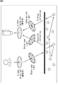
- FIG. 1 shows a state in which light emitted from a light source is reflected by an analysis target (skin in the present embodiment).
- the light reflected by the illumination light from the light source hits the analysis target is classified into specular reflection light and diffuse reflection light.
- the specular reflection light is light reflected at the same angle as the incident angle of the irradiation light.
- the diffuse reflected light is light reflected in various directions regardless of the incident angle of the irradiation light.
- the irradiation light is polarized, the polarization state is lost and reflected.
- FIG. 2 shows that a polarizing plate (hereinafter referred to as a polarizer) is provided in front of a light source (optical path of irradiation light), and a polarizing plate (hereinafter referred to as an optical path of reflected light) in front of a camera for imaging an analysis target. , Referred to as an analyzer).
- a polarizing plate hereinafter referred to as a polarizer
- an optical path of reflected light a polarizing plate
- the irradiation light from the light source is irradiated to the analysis target in a polarization state corresponding to the polarizer, and the mirror reflection light is maintained in the polarization state by the polarizer. Therefore, by adjusting the polarization direction of the polarizer or analyzer, the amount of specular reflected light incident on the camera can be controlled.
- the specular reflection light can pass through the analyzer and reach the camera as it is.
- the polarization directions of the polarizer and the analyzer are orthogonal, the specular reflection light is blocked by the analyzer and does not reach the camera.
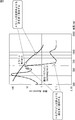
- each substance has a unique light absorption spectrum. Therefore, a spectroscopic measurement method for identifying a substance has been established by irradiating an unknown sample with light whose wavelength is continuously converted, measuring the reflected light intensity, and comparing it with a known spectrum.
- FIG. 3 shows light absorption spectra of hemoglobin and melanin.
- hemoglobin has the property of absorbing more green light near a wavelength of 550 nm than red light near a wavelength of 650 nm. Therefore, when the reflected light intensity is measured using the illumination light having these two wavelengths, the reflection of green light is relatively lower than the reflection of red light in a substance containing a large amount of hemoglobin. This can be used to measure the presence or amount of hemoglobin.
- melanin pigment the same measurement can be performed using near-infrared light having a wavelength of about 950 nm and red light having a wavelength of about 650 nm.
- lupus erythematosus erythema
- lupus erythema lupus erythema
- a phenomenon in which energy such as light or heat given to a substance is emitted as light from the substance is called luminescence, and light emitted at that time is called fluorescence.
- a substance in which luminescence occurs is called a phosphor.
- the irradiated light is often ultraviolet rays or X-rays outside the visible light range.
- ultraviolet light and X-rays cannot be seen with the naked eye, and cannot be captured with a general camera.
- the wavelength of the fluorescence excited by ultraviolet light or X-rays is in the visible light range, the presence or amount of the phosphor is measured by observing it with the naked eye or taking an image with a camera. be able to.
- porphyrin the waste product of acne bacteria causing acne
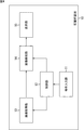
- FIG. 4 illustrates a configuration example of a skin analysis apparatus that is an embodiment of the present disclosure.
- the skin analysis device 10 includes an operation input unit 11, a control unit 12, an image acquisition unit 13, an image analysis unit 14, and a display unit 15.
- the operation input unit 11 receives, for example, a user's operation for selecting a measurement item related to skin (for example, skin color, shine, pores, texture, melanin index, lupus erythema index, porphyrin, etc.) and controls the operation signal.
- a measurement item related to skin for example, skin color, shine, pores, texture, melanin index, lupus erythema index, porphyrin, etc.
- the control unit 12 controls the image acquisition unit 13 and the image analysis unit 14 based on the operation signal from the operation input unit 11.
- the image acquisition unit 13 includes at least a light source that emits irradiation light to an analysis target (in the case of the present embodiment, skin) and a camera that images the analysis target in a state where the irradiation light is irradiated.
- An image obtained as a result of imaging is output to the image analysis unit 14.
- the image analysis unit 14 analyzes the image input from the image acquisition unit 13 to measure each measurement item regarding the skin and outputs the measurement result to the display unit 15.
- the display unit 15 displays the measurement result obtained by the image analysis unit 14. Instead of providing the image analysis unit 14, image analysis may be performed using so-called cloud computing.
- the measurement result may be displayed on another device (such as a personal computer or a smartphone) that can be connected to the network.
- the image acquisition unit 13 irradiates the analysis target with irradiation light and performs imaging, and the image obtained as a result is analyzed by the image analysis unit 14.
- the analysis result is displayed on the display unit 15.
- FIG. 5 shows a cross section of a first configuration example of the image acquisition unit 13.
- the first configuration example includes a camera 21 that images an analysis target, an analyzer 22 that includes a polarizing plate, a PCB (Printed Circuit Board) 23 that includes an FPC (Flexible printed circuits) that fixes and controls the illumination unit 24, and the like.
- the illumination unit 24 includes a plurality of light sources (LEDs) and a polarizer 25 including a polarizing plate.
- the irradiation direction of the illumination unit 24 is arranged in a direction facing the analysis target, and a polarizer 25 is arranged in front of the illumination unit 24 (optical path of irradiation light). ing. Therefore, the irradiation light irradiated from the illumination unit 24 is irradiated to the analysis target via the polarizer 25.
- an analyzer 22 is disposed in front of the camera 21 (the optical path of the reflected light from the analysis target). Accordingly, the reflected light from the analysis target is incident on the camera 21 via the analyzer 22.
- FIG. 6 shows a cross section of a second configuration example of the image acquisition unit 13.
- the second configuration example includes a camera 21, an analyzer 22, a PCB 23, an illumination unit 24, a polarizer 25, and a light guide 31.
- the description is abbreviate
- the light guide 31 is made of, for example, an optical member such as a lens, a light pipe, or an optical fiber, and irradiates the skin observation area by bending the traveling direction of the irradiation light emitted from the illumination unit 24.
- the central axis of the illumination unit 24 (the light source included therein) and the central axis of the light guide 31 do not necessarily have to coincide with each other. Rather, by illuminating the central axes of the two, irradiation light from an oblique direction can be more efficiently irradiated.
- the irradiation direction of the illuminating unit 24 is arranged not facing the analysis target but facing the side surface of the casing. Further, a light guide 31 and a polarizer 25 are disposed in front of the illumination unit 24.
- the 2nd example of composition can reduce the size of the whole image acquisition part 13 compared with the 1st example of composition.
- the irradiation direction of the illumination unit 24 is not directed downward of the housing, glare when the image acquisition unit 13 is viewed from the lower part of the housing can be suppressed.
- the irradiation light irradiated from the illumination unit 24 is irradiated to the analysis target via the light guide 31 and the polarizer 25.
- FIG. 7 shows a cross section of a third configuration example of the image acquisition unit 13.
- the third configuration example includes a camera 21, an analyzer 22, a PCB 23, an illumination unit 24, a polarizer 25, and a light guide 31.
- the description is abbreviate
- the irradiation direction of the illuminating unit 24 does not face the analysis target, but is arranged toward the upper surface of the housing.
- the light guide 31 and the polarizer are arranged. 25 is arranged.
- the size of the whole image acquisition part 13 can also be reduced also in the 3rd example of composition compared with the 1st example of composition.
- the irradiation direction of the illumination unit 24 does not face downward of the housing, glare when the image acquisition unit 13 is viewed from the lower direction of the housing can be suppressed.
- the irradiation light irradiated from the illumination unit 24 is irradiated to the analysis target via the light guide 31 and the polarizer 25.
- the optical surface shape of the light guide 31 is not limited to that shown in the figure.
- a curved surface, an aspherical surface, a free curved surface, etc. are arbitrary.
- FIG. 8 shows a first arrangement example of light sources constituting the planar illumination unit 24.
- the illumination unit 24 includes four LEDs 51-1 to 51-4, which are arranged at equal intervals around the optical axis of the camera 21.
- Each LED 51 employs one package of four chips each generating R (red), G (green), B (blue), and IR (infrared) light having different wavelengths.
- each chip can be turned on and off independently.
- an analyzer 22 arranged in front of the camera 21 and a polarizer 25p whose polarization direction is parallel are arranged in front of the camera 21 and a polarizer 25p whose polarization direction is parallel.
- a polarizer 25r whose polarization direction is orthogonal to the analyzer 22 is disposed in front of the LEDs 51-1 and 51-3 (optical path of the irradiation light).
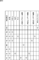
- FIG. 9 shows the correspondence between the measurement items and the lighting of the light source in the first arrangement example shown in FIG.
- Rr means light having an R wavelength, and is irradiated through a polarizer 25r whose polarization direction is orthogonal to the analyzer 22.
- Rp means light having a wavelength of R and irradiated through a polarizer 25p whose polarization direction is parallel to the analyzer 22. The same applies to irradiation light with other wavelengths. The same applies to the following drawings.
- Rr, Gr, Br and Rp, Gp, Bp are simultaneously turned on to emit light equivalent to white light.
- specular reflection light and diffuse reflection light are imaged, it is possible to acquire an image with conditions close to the human eye.
- the reason why the wavelength of light to be irradiated is G is that the sensitivity of the camera 21 is higher than other wavelengths, but Rp, Bp or IRp is turned on instead of Gp. May be.
- the diffused reflected light of red light whose degree of reflection changes depending on the presence or absence of the internal melanin pigment is used.
- a red image is acquired by imaging.
- an infrared image is picked up by picking up an infrared diffuse reflected light whose degree of reflection hardly changes depending on the presence or absence of an internal melanin pigment.
- the image analysis unit 14 analyzes the amount and distribution of the internal melanin pigment based on the difference between the red image and the infrared image. The measurement of the internal melanin pigment is used to predict the melanin pigment that will appear in the stratum corneum in the future.
- the red light whose degree of reflection changes depending on the presence or absence of the melanin pigment on the surface (stratum corneum) with only the analyzer 22 and the polarization direction Rp parallel to each other.
- a red image is acquired by imaging the specular reflection light.
- an infrared image is captured by imaging infrared specularly reflected light whose degree of reflection hardly changes depending on the presence or absence of the melanin pigment on the surface. Take an image.
- the image analysis unit 14 analyzes the amount and distribution of the surface melanin pigment based on the difference between the red image and the infrared image.
- a red image is acquired by imaging the diffuse reflected light of red light with only the analyzer 22 and Rr whose polarization directions are orthogonal to each other.
- a green image is acquired by imaging diffuse reflected light of green light in a state where only Gr whose polarization direction is orthogonal to the analyzer 22 is turned on.
- Hemoglobin that causes lupus (erythema) absorbs green light well, but hardly absorbs red light. Therefore, the image analysis unit 14 analyzes the amount and distribution of internal hemoglobin based on the difference between the green image and the red image. To do. The measurement of internal hemoglobin is used to observe the state of capillaries in the dermis layer.
- a red image is obtained by imaging the specular reflected light of red light with only the analyzer 22 and Rp having a polarization direction parallel to each other.
- a green image is acquired by imaging the specular reflected light of green light in a state where only the Gp whose polarization direction is parallel to the analyzer 22 is turned on.
- the image analysis unit 14 analyzes the amount and distribution of surface hemoglobin based on the difference between the green image and the red image. The measurement of surface hemoglobin is used for observation of the state of capillaries near the epidermis layer.
- FIG. 10 shows a second arrangement example of light sources constituting the planar illumination unit 24.
- the illumination unit 24 includes four LEDs 61-1 to 61-4, which are arranged at equal intervals around the optical axis of the camera 21.
- Each LED 61 employs a single package of four chips each generating R, G, B, and UV (ultraviolet) light having different wavelengths. In each LED 61, each chip can be turned on and off independently.
- an analyzer 22 arranged in front of the camera 21 and a polarizer 25p whose polarization direction is parallel are arranged in front of the camera 21 and a polarizer 25p whose polarization direction is parallel.
- a polarizer 25r whose polarization direction is orthogonal to the analyzer 22 is disposed in front of the LEDs 61-2 and 61-4.
- a UV chip is used instead of the IR chip included in the LED 51 of the first arrangement example of FIG. This makes it impossible to measure the melanin index, but instead, it is possible to measure porphyrin by fluorescence excitation of UV light.
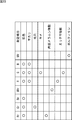
- FIG. 11 shows the correspondence between measurement items and lighting of the light source in the second arrangement example shown in FIG.
- Measurement of skin color, shine, pores, texture, internal lupus erythema index, and surface lupus erythema index to be analyzed is the same as in the first arrangement example described above.
- FIG. 12 shows a third arrangement example of light sources constituting the planar illumination unit 24.
- the illumination unit 24 is configured by four LEDs 71-1 and 71-3, and LEDs 72-2 and 72-4, which are arranged around the optical axis of the camera 21 as a center. Are arranged at equal intervals.
- the LEDs 71-1 and 71-3 four chips each generating R, G, B, and UV light having different wavelengths are packaged in one package.
- a polarizer 25 p In front of the LEDs 71-1 and 71-3 (irradiation light optical path), a polarizer 25 p whose polarization direction is parallel to the analyzer 22 is arranged.
- the LEDs 72-2 and 72-4 employ one package of four chips that respectively generate R, G, B, and IR light having different wavelengths.
- a polarizer 25r whose polarization direction is orthogonal to the analyzer 22 is disposed.
- the LEDs 71 and 72 can be turned on and off independently of each chip inside.
- the third arrangement example is a combination of the first arrangement example of FIG. 8 and the second arrangement example of FIG. 10, and the skin color, shine, pores, texture, and internal melanin to be analyzed Measurements of index, internal lupus index, surface lupus index, and porphine are possible.
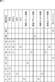
- FIG. 13 shows the correspondence between the measurement items and the lighting of the light source in the third arrangement example shown in FIG.
- the measurement of skin color, shine, pores, texture, internal melanin index, internal lupus erythema index, and surface lupus erythema index to be analyzed is the same as in the first configuration example described above.
- the measurement of porphine is the same as in the case of the second configuration example described above.
- FIG. 14 shows a fourth arrangement example of the light sources constituting the planar illumination unit 24.
- the illumination unit 24 is configured by four LEDs 81-1 and 81-3, and LEDs 82-2 and 82-4, which are arranged around the optical axis of the camera 21 as a center. Are arranged at equal intervals.
- the LEDs 81-1 and 81-3 one in which four chips of R, G, B, and UV having different wavelengths are packaged is adopted.
- the LEDs 82-2 and 82-4 adopt one package of 4 chips of R, G, B, and IR having different wavelengths.
- a polarizer 25r whose polarization direction is orthogonal to the analyzer 22 is disposed.
- the LEDs 81 and 82 can be turned on and off independently of each chip inside.
- the analyzer 25 and the polarizer 25p whose polarization direction is parallel are omitted from the third arrangement example in FIG.
- irradiation light whose polarization direction is parallel to the analyzer 22 cannot be irradiated, so that the state of the skin surface cannot be intensively measured. Therefore, in the fourth arrangement example, skin shine and texture can be measured, but the ability is inferior to that in the first arrangement example in FIG.
- FIG. 15 shows the correspondence between the measurement items and the lighting of the light source in the fourth arrangement example shown in FIG.
- the measurement of skin color, shine, pores, texture, internal melanin index, lupus erythema index, and porphyrin as the analysis target is the same as in any of the first to third arrangement examples described above.
- FIG. 16 shows a fifth arrangement example of the light sources constituting the planar illumination unit 24.
- the illumination unit 24 includes four LEDs 91-1 to 91-4, which are arranged at equal intervals around the optical axis of the camera 21.
- the LEDs 91-1 to 91-4 one in which 5 chips each generating R, G, B, IR, and UV light having different wavelengths are packaged is adopted.
- each internal chip can be turned on and off independently.
- an analyzer 22 and a polarizer 25p whose polarization direction is parallel are arranged in front of the LEDs 91-2 and 91-4.
- a polarizer 25r whose polarization direction is orthogonal to the analyzer 22 is disposed in front of the LEDs 91-2 and 91-4.
- FIG. 17 shows the correspondence between the measurement items and the lighting of the light sources in the fifth arrangement example shown in FIG.
- FIG. 18 shows a sixth arrangement example of the light sources constituting the planar illumination unit 24.
- the illumination unit 24 is configured by eight LEDs 101-1 to 101-4, and 102-1 to 102-4, which are arranged around the optical axis of the camera 21 as a center. Are arranged at equal intervals.
- the LEDs 101-1 to 101-4 four chips each generating R, G, IR, and UV light having different wavelengths are packaged in one package.
- the LED 101 can be turned on and off independently for each chip inside.
- LEDs 102-1 to 102-4 LEDs that generate W (white light) light are employed.
- a polarizer 25p having a polarization direction parallel to the analyzer 22 is disposed.
- a polarizer 25r whose polarization direction is orthogonal to the analyzer 22 is disposed.
- FIG. 19 shows the correspondence between measurement items and lighting of the light source in the sixth arrangement example shown in FIG.
- Wr and Wp are turned on. Therefore, since the specular reflection light and diffuse reflection light of white light are imaged, it is possible to acquire an image under conditions close to the human eye.
- Wp that is polarized parallel to the analyzer 22 When measuring shine, Wp that is polarized parallel to the analyzer 22 is turned on. Thereby, since diffuse reflection light of white light is not generated and only specular reflection light is imaged, a shine image that is reflection on the skin surface can be acquired.
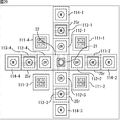
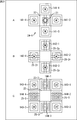
- FIG. 20 shows a seventh arrangement example of the light sources constituting the planar illumination unit 24.
- the illumination unit 24 includes 16 LEDs 111-1 to 111-4, LEDs 112-1 to 112-4, LEDs 113-1 to 113-4, and LEDs 114-1 to 114-4. These are arranged at equal intervals around the optical axis of the camera 21.
- the LEDs 111-1 to 111-4 adopt four-chips that each generate R, G, G, and IR light having different wavelengths in one package. Note that two G chips are provided in one package because the light emission output thereof is smaller than that of the R chip. In each LED 111, the R, G, and IR chips can be turned on and off independently.
- LEDs that generate UV light are adopted as the LEDs 112-1 to 112-4.
- LEDs that generate W light are used for the LEDs 113-1 to 113-4.
- a polarizer 25r whose polarization direction is orthogonal to the analyzer 22 is disposed.
- LEDs that generate W light are used for the LEDs 114-1 to 114-4.
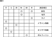
- FIG. 21 shows the correspondence between the measurement items and the lighting of the light source in the seventh arrangement example shown in FIG.
- the measurement of skin color, pores, texture, melanin index, lupus erythema index, and porphyrin as the analysis target is the same as in any of the first to sixth arrangement examples described above.
- the first to seventh arrangement examples of the light sources constituting the illumination unit 24 described above can be combined with any of the first to third configuration examples of the image acquisition unit 13, respectively.
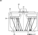
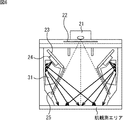
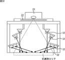
- FIG. 22 shows a cross section of a fourth configuration example of the image acquisition unit 13.
- the fourth configuration example includes a camera 21, an analyzer 22, and a PCB 23, an illumination unit 24, and a polarizer 25 that are three-dimensionally divided into three layers.
- the PCB 23, the illumination unit 24, and the polarizer 25 are three-dimensionally arranged in three layers. That is, the first layer includes the PCB 23-1, the illumination unit 24-1, and the polarizer 25-1.
- the second layer includes a PCB 23-2, an illumination unit 24-2, and a polarizer 25-2.
- the third layer includes a PCB 23-3 and an illumination unit 24-2.
- the illumination units 24-1 to 24-3 are arranged at different angles so that the respective irradiation directions face the analysis target.
- polarizers 25-1 and 25-2 are arranged, respectively. Note that the polarizer 25-1 or 25-2 may be omitted, or a polarizer may be disposed in front of the illumination unit 24-3.
- the fourth configuration example is smaller in size than the first to third configuration examples described above.
- the illumination unit 24 when configured in a three-dimensional manner, it may have three layers as shown in FIG. 22, two layers, or four or more layers.
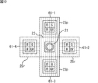
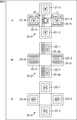
- FIG. 23 shows an arrangement example of light sources (hereinafter referred to as an eighth arrangement example) constituting the three-dimensional illumination units 24-1 to 24-3 in FIG.
- the illumination unit 24-1 arranged in the first layer is composed of four LEDs 121-1 to 121-4 as shown in FIG. A, and these are centered on the optical axis of the camera 21. It is arranged at equal intervals around it. Each LED 121 employs an LED that generates W (white light) light. In front of the LEDs 121-2 and 121-4, a polarizer 25-1r whose polarization direction is orthogonal to the analyzer 22 disposed in front of the camera 21 is disposed.
- the illumination unit 24-2 arranged in the second layer is composed of four LEDs 122-1 to 122-4 as shown in FIG. B, and these are centered on the optical axis of the camera 21. It is arranged at equal intervals around it.
- Each LED 122 employs a single package of four chips each generating R, G, B, and IR light having different wavelengths. In each LED 122, each chip can be turned on and off independently.
- an analyzer 22 arranged in front of the camera 21 and a polarizer 25-2p whose polarization direction is parallel are arranged.
- a polarizer 25-2r whose polarization direction is orthogonal to the analyzer 22 disposed in front of the camera 21 is disposed.
- the illumination unit 24-3 arranged in the third layer is composed of four LEDs 123-1 to 123-4 as shown in FIG. C, and these are centered on the optical axis of the camera 21. It is arranged at equal intervals around it. Each LED 123 employs an LED that generates UV light.
- the illumination units 24-1 to 24-3 can be rotated around the optical axis of the camera 21, and the second-layer illumination unit 24-2 is irradiated with the third-layer illumination unit 24- 3 is arranged at a position not shielded by 3.
- the first layer illumination unit 24-1 is disposed at a position where the light to be irradiated is not shielded by the second layer illumination unit 24-2 and the third layer 24-3.
- an LED having a relatively small output is arranged in a layer closer to the skin observation area (for example, a UV LED having a relatively small output is relatively output on the third layer).
- a UV LED having a relatively small output is relatively output on the third layer.
- the arrangement of these LEDs is not limited to the example shown in the figure and is arbitrary.
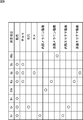
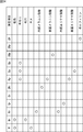
- FIG. 24 shows the correspondence between the measurement items and the lighting of the light source in the eighth arrangement example shown in FIG.
- Measurement of skin color, shine, pores, texture, internal melanin index, surface melanin index, internal lupus erythema index, surface lupus erythema index, and porphine to be analyzed is any one of the first to seventh arrangement examples described above. Same as the case.
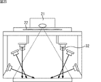
- FIG. 25 illustrates a cross section of a fifth configuration example of the image acquisition unit 13.
- a lens 32 as a light guide is disposed in front of the first-layer illumination unit 24-1 in the fourth configuration example shown in FIG.
- the description is abbreviate
- any arrangement other than the eighth arrangement example shown in FIG. 23 can be adopted.
- the lens 32 irradiates the skin observation area by bending in the traveling direction of the irradiation light emitted by the illumination unit 24-1.
- the lens 32 By arranging the lens 32, it is possible to efficiently irradiate the irradiation light emitted from the illumination unit 24-1.
- the central axis of the illumination unit 24-1 (the light source included therein) and the central axis of the lens 32 are not necessarily matched. Rather, there are cases where irradiation light can be irradiated more efficiently by decentering the central axes of both.
- the lens 32 may be disposed in front of at least one of the illumination units 24-2 or 24-3 instead of or in addition to the illumination unit 24-1.
- FIG. 26 shows a cross section of a sixth configuration example of the image acquisition unit 13.
- a light pipe 33 as a light guide is disposed in front of the first-layer illumination unit 24-1 in the fourth configuration example shown in FIG.
- the description is abbreviate
- any arrangement other than the eighth arrangement example shown in FIG. 23 can be adopted.
- the light pipe 33 is bent in the traveling direction of the irradiation light emitted from the illumination unit 24-1, and irradiates the skin observation area. By arranging the light pipe 33, the irradiation light emitted from the illumination unit 24-1 can be efficiently irradiated.
- the central axis of the illumination unit 24-1 (the light source included therein) and the central axis of the light pipe 33 do not necessarily coincide with each other. Rather, there are cases where irradiation light can be irradiated more efficiently by decentering the central axes of both.
- the light pipe 33 may be disposed in front of at least one of the illumination units 24-2 or 24-3 instead of or in addition to the illumination unit 24-1.
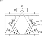
- FIG. 27 shows a cross section of a seventh configuration example of the image acquisition unit 13.
- a light pipe 33 as a light guide is arranged in front of the first layer illumination unit 24-1 in the fourth configuration example shown in FIG.
- a lens 32 as a light guide is disposed in front of the portion 24-2 and in front of the third layer illumination portion 24-3.
- the description is abbreviate
- any arrangement other than the eighth arrangement example shown in FIG. 23 can be adopted.
- the lens 32 irradiates the skin observation area by bending in the traveling direction of the irradiation light emitted by the illumination units 24-2 and 24-3.
- the light pipe 33 irradiates the skin observation area by bending in the traveling direction of the irradiation light emitted from the illumination unit 24-1.
- central axes of the lens 32 and the light pipe 33 do not necessarily need to coincide with the central axes of any of the corresponding illumination units 24-1 to 24-3 (light sources included therein). Rather, there are cases where irradiation light can be irradiated more efficiently by decentering the central axes of both.
- the light pipe 33 may be disposed at a position where the lens 32 is disposed, or conversely, the lens 32 may be disposed at a position where the light pipe 33 is disposed.
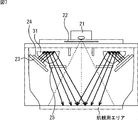
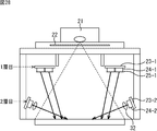
- FIG. 28 shows a cross section of an eighth configuration example of the image acquisition unit 13.
- the eighth configuration example includes a camera 21, an analyzer 22, and a PCB 23, an illumination unit 24, and a polarizer 25 that are three-dimensionally divided into two layers.
- the PCB 23, the illumination unit 24, and the polarizer 25 are divided into two layers and arranged three-dimensionally. That is, the first layer includes the PCB 23-1, the illumination unit 24-1, and the polarizer 25-1.
- the second layer includes a PCB 23-2, an illumination unit 24-2, and a lens 32.
- the illumination units 24-1 and 24-2 are arranged at different angles so that the respective irradiation directions face the analysis target.
- the eighth configuration example is smaller in size of the image acquisition unit 13 than the first to third configuration examples described above.
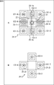
- FIG. 29 shows an arrangement example of light sources (hereinafter referred to as a ninth arrangement example) constituting the three-dimensional illumination units 24-1 and 24-2 of FIG.
- the lighting unit 24-1 arranged in the first layer is composed of eight LEDs 131-1 to 131-4 and LEDs 132-1 to 132-4 as shown in FIG. These are arranged at equal intervals around the optical axis of the camera 21.
- Each LED 131 employs an LED that generates UV light.
- Each LED 132 employs a single package of four chips that generate R, G, B, and IR light having different wavelengths. In each LED 132, each chip can be turned on and off independently.
- an analyzer 22 disposed in front of the camera 21 and a polarizer 25-1p whose polarization direction is parallel are disposed.
- a polarizer 25-1r whose polarization direction is orthogonal to the analyzer 22 disposed in front of the camera 21 is disposed.
- the illumination unit 24-2 arranged in the second layer is composed of four LEDs 13-1 to 133-4 as shown in FIG. B, and these are centered on the optical axis of the camera 21. It is arranged at equal intervals around it. Each LED 133 employs an LED that generates W light. In front of the LEDs 133-2 and 133-4, a polarizer 25-2r whose polarization direction is orthogonal to the analyzer 22 disposed in front of the camera 21 is disposed.
- the illumination units 24-1 and 24-2 can be rotated around the optical axis of the camera 21, and the first layer illumination unit 24-1 emits light to the second layer illumination unit 24- 2 is arranged at a position that is not shielded by 2.
- the ninth arrangement example many LEDs are arranged in the first layer far from the skin observation area, but conversely, many LEDs may be arranged in the second layer. Further, the configuration of the LED and the chip constituting one package is not limited to the illustrated example, and is arbitrary.
- the correspondence between the measurement item and the light source lighting in the ninth arrangement example is the same as the correspondence between the measurement item and the light source lighting in the eighth arrangement example described with reference to FIG. Is omitted.
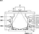
- FIG. 30 shows a cross section of a ninth configuration example of the image acquisition unit 13.
- the ninth configuration example includes a camera 21, an analyzer 22, and a PCB 23, an illumination unit 24, and a polarizer 25 that are three-dimensionally divided into three layers.
- the PCB 23, the illumination unit 24, and the polarizer 25 are three-dimensionally arranged in three layers. That is, the first layer includes the PCB 23-1, the illumination unit 24-1, and the polarizer 25-1.
- the second layer includes a PCB 23-2, an illumination unit 24-2, a polarizer 25-2, and a lens 32.
- the third layer includes a PCB 23-3, an illumination unit 24-3, and a lens 32. However, the third-layer lens 32 is used as a part of the illumination unit 24-3.
- the illumination units 24-1 to 24-3 are arranged at different angles so that the respective irradiation directions face the analysis target.
- the ninth configuration example is smaller in size than the first to third configuration examples described above.
- FIG. 31 shows an arrangement example of light sources (hereinafter referred to as a ninth arrangement example) constituting the three-dimensional illumination units 24-1 to 24-3 in FIG.
- the lighting unit 24-1 arranged in the first layer is composed of four LEDs 141-1 to 141-4 as shown in FIG. A, and these are centered on the optical axis of the camera 21. It is arranged at equal intervals around it. Each LED 141 employs an LED that generates W light.
- the illumination unit 24-2 arranged in the second layer is composed of four LEDs 142-1 to 142-4 as shown in FIG. B, and these are centered on the optical axis of the camera 21. It is arranged at equal intervals around it.
- Each LED 142 employs an LED that generates W light.
- an analyzer 22 arranged in front of the camera 21 and a polarizer 25-2p whose polarization direction is parallel are arranged.
- a polarizer 25-2p whose polarization direction is orthogonal to the analyzer 22 disposed in front of the camera 21 is disposed.
- the illumination unit 24-2 arranged in the third layer is composed of eight LEDs 143-1 to 143-4 and LEDs 144-1 to 144-4 as shown in FIG. These are arranged at equal intervals around the optical axis of the camera 21.
- Each LED 143 employs an LED that generates UV light.
- Each LED 144 employs one package of four chips that generate R, G, B, and IR light having different wavelengths. In each LED 144, each chip can be turned on and off independently.
- a polarizer 25-3 p having a polarization direction parallel to the analyzer 22 disposed in front of the camera 21 is disposed.
- a polarizer 25-3r having a polarization direction orthogonal to the analyzer 22 disposed in front of the camera 21 is disposed.
- the illumination units 24-1 to 24-3 can be rotated around the optical axis of the camera 21, and the second-layer illumination unit 24-2 is irradiated with the third-layer illumination unit 24- 3 is arranged at a position not shielded by 3.
- the first layer illumination unit 24-1 is disposed at a position where the light to be irradiated is not shielded by the second layer illumination unit 24-2 and the third layer 24-3.
- many LEDs are arranged on the third layer closest to the skin observation area.
- many LEDs may be arranged on the first layer or the second layer.
- the configuration of the LED and the chip constituting one package is not limited to the illustrated example, and is arbitrary.
- the correspondence between the measurement item and the light source lighting in the tenth arrangement example is the same as the correspondence between the measurement item and the light source lighting in the eighth arrangement example described with reference to FIG. Is omitted.
- FIG. 32 shows a cross section of a tenth configuration example of the image acquisition unit 13.
- a lens 32 as a light guide is arranged in front of each of the illumination units 24-1 to 24-3 in the ninth configuration example shown in FIG.
- the description is abbreviate
- any arrangement other than the tenth arrangement example shown in FIG. 31 can be adopted.
- the lens 32 irradiates the skin observation area by bending in the traveling direction of the irradiation light emitted from the illumination units 24-1 to 24-3.
- By arranging the lens 32 it is possible to efficiently irradiate the irradiation light emitted from the illumination units 24-1 to 24-3.
- central axes of the illumination units 24-1 to 24-3 (light sources included therein) and the central axes of the lenses 32 corresponding to them do not necessarily have to coincide with each other. Rather, there are cases where irradiation light can be irradiated more efficiently by decentering the central axes of both.
- an arbitrary light guide such as a light pipe may be arranged.
- the above-described series of processing can be executed by hardware or can be executed by software.
- a program constituting the software is installed in the computer.
- the computer includes, for example, a general-purpose personal computer capable of executing various functions by installing a computer incorporated in dedicated hardware and various programs.
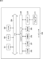
- FIG. 33 is a block diagram illustrating a configuration example of hardware of a computer that executes the above-described series of processing by a program.
- a CPU Central Processing Unit
- ROM Read Only Memory
- RAM Random Access Memory
- An input / output interface 205 is further connected to the bus 204.
- An input unit 206, an output unit 207, a storage unit 208, a communication unit 209, and a drive 210 are connected to the input / output interface 205.
- the input unit 206 includes a keyboard, a mouse, a microphone, and the like.
- the output unit 207 includes a display, a speaker, and the like.
- the storage unit 208 includes a hard disk, a nonvolatile memory, and the like.
- the communication unit 209 includes a network interface and the like.
- the drive 210 drives a removable medium 211 such as a magnetic disk, an optical disk, a magneto-optical disk, or a semiconductor memory.
- the CPU 201 loads the program stored in the storage unit 208 to the RAM 203 via the input / output interface 205 and the bus 204 and executes the program. A series of processing is performed.
- the program executed by the computer 200 can be provided by being recorded in, for example, a removable medium 211 such as a package medium.
- the program can be provided via a wired or wireless transmission medium such as a local area network, the Internet, or digital satellite broadcasting.
- the program can be installed in the storage unit 208 via the input / output interface 205 by attaching the removable medium 211 to the drive 210.
- the program can be received by the communication unit 209 via a wired or wireless transmission medium and installed in the storage unit 208.
- the program can be installed in the ROM 202 or the storage unit 208 in advance.
- the program executed by the computer 200 may be a program that is processed in time series in the order described in this specification, or a necessary timing such as when a call is made in parallel. It may be a program in which processing is performed.
- a lighting unit comprising a light emitting unit in which a plurality of light emitting elements including at least a light emitting element that emits visible light and a light emitting element that emits invisible light are packaged;
- An image analysis apparatus comprising: an image acquisition unit including: an imaging unit that captures reflected light generated when the irradiation light emitted from the illumination unit is reflected by an analysis target.
- the light emitting unit is packaged with a plurality of light emitting elements including at least a light emitting element that emits visible red light, a light emitting element that emits visible green light, and a light emitting element that emits invisible infrared light.
- the image acquisition unit A polarizer disposed on an optical path of the irradiation light emitted from the illumination unit;
- the image acquisition unit The image analysis apparatus according to any one of (1) to (3), further including a light guide that guides the irradiation light emitted from the irradiation unit to the analysis target.
- the optical surface shape of the said light guide is arbitrary. The image analysis apparatus as described in said (4).
- the illumination unit includes a plurality of the light emitting units, The image analysis device according to any one of (1) to (5), wherein the plurality of light emitting units are arranged at equal intervals around an optical axis of the imaging unit. (7) The image analysis device according to (6), wherein the plurality of light emitting units forming the illumination unit are arranged at equal intervals around the optical axis of the imaging unit in a plane. (8) The image analysis device according to (6), wherein the plurality of light emitting units forming the illumination unit are multi-layered and are three-dimensionally arranged at equal intervals around the optical axis of the imaging unit.
- the image analysis device according to any one of (6) to (8), wherein the plurality of light emitting units constituting the illumination unit are arranged with different angles so as to face the analysis target.
- the image analysis apparatus according to any one of (1) to (9), wherein the illumination unit changes a wavelength of the irradiation light by changing the light emitting element that emits light according to an analysis item.
- the image analysis apparatus according to (10), further including an operation input unit that inputs an operation of a user who selects the analysis item.
- the image analysis device according to any one of (1) to (11), further including an image analysis unit that analyzes an image obtained as a result of imaging by the imaging unit.
- a lighting unit comprising a light emitting unit in which a plurality of light emitting elements including at least a light emitting element that emits visible light and a light emitting element that emits invisible light are packaged;
- an image analysis method by an image analysis apparatus comprising: an image acquisition unit including: an imaging unit that captures reflected light generated when the irradiation light irradiated from the illumination unit is reflected by an analysis target; An irradiation step of irradiating irradiation light by the illumination unit; An image analysis method including: an imaging step of imaging reflected light generated by the imaging unit when the irradiation light irradiated from the illumination unit is reflected by an analysis target.
- a lighting unit comprising a light emitting unit in which a plurality of light emitting elements including at least a light emitting element that emits visible light and a light emitting element that emits invisible light are packaged;
- a program for controlling an image analysis apparatus comprising: an image acquisition unit having an imaging unit that captures reflected light generated when the irradiation light emitted from the illumination unit is reflected by an analysis target; An irradiation step of controlling the illumination unit to irradiate irradiation light; and A program for controlling the imaging unit to cause the computer of the image analysis apparatus to execute processing including imaging step of imaging reflected light generated when the irradiation light irradiated from the illumination unit is reflected by the analysis target.
- a lighting device comprising: a plurality of light emitting units in which a plurality of light emitting elements including at least a light emitting element that emits visible light and a light emitting element that emits invisible light are packaged.
Landscapes
- Health & Medical Sciences (AREA)
- Life Sciences & Earth Sciences (AREA)
- Physics & Mathematics (AREA)
- Engineering & Computer Science (AREA)
- General Health & Medical Sciences (AREA)
- Pathology (AREA)
- Medical Informatics (AREA)
- Molecular Biology (AREA)
- Public Health (AREA)
- Biomedical Technology (AREA)
- Veterinary Medicine (AREA)
- Surgery (AREA)
- Animal Behavior & Ethology (AREA)
- Biophysics (AREA)
- Heart & Thoracic Surgery (AREA)
- General Physics & Mathematics (AREA)
- Immunology (AREA)
- Spectroscopy & Molecular Physics (AREA)
- Theoretical Computer Science (AREA)
- Chemical & Material Sciences (AREA)
- Analytical Chemistry (AREA)
- Biochemistry (AREA)
- Mathematical Physics (AREA)
- Dermatology (AREA)
- Nuclear Medicine, Radiotherapy & Molecular Imaging (AREA)
- Radiology & Medical Imaging (AREA)
- Quality & Reliability (AREA)
- Computer Vision & Pattern Recognition (AREA)
- Investigating Or Analysing Materials By Optical Means (AREA)
- Measuring And Recording Apparatus For Diagnosis (AREA)
- Measurement Of The Respiration, Hearing Ability, Form, And Blood Characteristics Of Living Organisms (AREA)
- Image Input (AREA)
- Image Processing (AREA)
- Image Analysis (AREA)
Abstract
Description
図4は、本開示の実施の形態である肌解析装置の構成例を示している。 <Example of configuration of skin analysis apparatus according to embodiment>
FIG. 4 illustrates a configuration example of a skin analysis apparatus that is an embodiment of the present disclosure.
肌解析装置10においては、ユーザにより選択された測定項目に従い、画像取得部13により解析対象に照射光が照射されて撮像が行われ、その結果得られた画像が画像解析部14により解析され、解析結果が表示部15に表示される。 <Operation of skin analyzer>
In the
次に、画像取得部13の詳細な構成例について説明する。 <Configuration Example of
Next, a detailed configuration example of the
図5は、画像取得部13の第1の構成例の断面を示している。該第1の構成例は、解析対象を撮像するカメラ21、偏光板から成る検光子22、照明部24を固定するとともに制御するFPC(Flexible printed circuits)などから成るPCB(Printed Circuit Board)23、複数の光源(LED)を含む照明部24、および偏光板から成る偏光子25から構成される。 <First Configuration Example of
FIG. 5 shows a cross section of a first configuration example of the
次に、図6は、画像取得部13の第2の構成例の断面を示している。該第2の構成例は、カメラ21、検光子22、PCB23、照明部24、偏光子25、および導光体31から構成される。なお、第1の構成例と共通する構成要素については同一の番号を付与しているので、その説明は省略する。 <Second Configuration Example of
Next, FIG. 6 shows a cross section of a second configuration example of the
次に、図7は、画像取得部13の第3の構成例の断面を示している。該第3の構成例は、第2の構成例と同様に、カメラ21、検光子22、PCB23、照明部24、偏光子25、および導光体31から構成される。なお、第1の構成例と共通する構成要素については同一の番号を付与しているので、その説明は省略する。 <Third Configuration Example of
Next, FIG. 7 shows a cross section of a third configuration example of the
次に、平面的な照明部24を構成する光源について説明する。なお、以下においては、平面的な照明部24を構成する光源の第1乃至第7の構成例を説明するが、これらは、上述した画像取得部13の第1乃至第3の構成例のいずれとも組み合わせることが可能である。 <About the light source which comprises the
Next, the light source which comprises the
図8は、平面的な照明部24を構成する光源の第1の配置例を示している。 <First Arrangement Example of Light Sources Constructing
FIG. 8 shows a first arrangement example of light sources constituting the
図10は、平面的な照明部24を構成する光源の第2の配置例を示している。 <Second Arrangement Example of Light Sources Constructing
FIG. 10 shows a second arrangement example of light sources constituting the
図12は、平面的な照明部24を構成する光源の第3の配置例を示している。 <Third arrangement example of light sources constituting the
FIG. 12 shows a third arrangement example of light sources constituting the
図14は、平面的な照明部24を構成する光源の第4の配置例を示している。 <The 4th example of arrangement of the light source which constitutes
FIG. 14 shows a fourth arrangement example of the light sources constituting the
図16は、平面的な照明部24を構成する光源の第5の配置例を示している。 <The 5th example of arrangement of the light source which constitutes
FIG. 16 shows a fifth arrangement example of the light sources constituting the
図18は、平面的な照明部24を構成する光源の第6の配置例を示している。 <The 6th example of arrangement of the light source which constitutes
FIG. 18 shows a sixth arrangement example of the light sources constituting the
図20は、平面的な照明部24を構成する光源の第7の配置例を示している。 <Seventh Arrangement Example of Light Sources that
FIG. 20 shows a seventh arrangement example of the light sources constituting the
次に、図22は、画像取得部13の第4の構成例の断面を示している。該第4の構成例は、カメラ21、検光子22、並びに、立体的に3層に分けて配置されたPCB23、照明部24および偏光子25から構成される。 <Fourth Configuration Example of
Next, FIG. 22 shows a cross section of a fourth configuration example of the
図23は、図22の立体的な照明部24-1乃至24-3を構成する光源の配置例(以下、第8の配置例と称する)を示している。 <Eighth Arrangement Example of Light Sources Constructing Illumination Units 24-1 to 24-3>
FIG. 23 shows an arrangement example of light sources (hereinafter referred to as an eighth arrangement example) constituting the three-dimensional illumination units 24-1 to 24-3 in FIG.
次に、図25は、画像取得部13の第5の構成例の断面を示している。該第5の構成例は、図22に示された第4の構成例における1層目の照明部24-1の前に、導光体としてのレンズ32を配置したものである。なお、第4の構成例と共通する構成要素については同一の番号を付与しているので、その説明は省略する。 <Fifth Configuration Example of
Next, FIG. 25 illustrates a cross section of a fifth configuration example of the
次に、図26は、画像取得部13の第6の構成例の断面を示している。該第6の構成例は、図22に示された第4の構成例における1層目の照明部24-1の前に、導光体としてのライトパイプ33を配置したものである。なお、第4の構成例と共通する構成要素については同一の番号を付与しているので、その説明は省略する。 <Sixth Configuration Example of
Next, FIG. 26 shows a cross section of a sixth configuration example of the
次に、図27は、画像取得部13の第7の構成例の断面を示している。該第7の構成例は、図22に示された第4の構成例における1層目の照明部24-1の前に、導光体としてのライトパイプ33を配置し、2層目の照明部24-2の前と、3層目の照明部24-3の前に導光体としてのレンズ32を配置したものである。なお、第4乃至6の構成例と共通する構成要素については同一の番号を付与しているので、その説明は省略する。 <Seventh Configuration Example of
Next, FIG. 27 shows a cross section of a seventh configuration example of the
次に、図28は、画像取得部13の第8の構成例の断面を示している。該第8の構成例は、カメラ21、検光子22、並びに、立体的に2層に分けて配置されたPCB23、照明部24および偏光子25から構成される。 <Eighth Configuration Example of
Next, FIG. 28 shows a cross section of an eighth configuration example of the
図29は、図28の立体的な照明部24-1および24-2を構成する光源の配置例(以下、第9の配置例と称する)を示している。 <Ninth Arrangement Example of Light Sources Constructing Illumination Units 24-1 and 24-2>
FIG. 29 shows an arrangement example of light sources (hereinafter referred to as a ninth arrangement example) constituting the three-dimensional illumination units 24-1 and 24-2 of FIG.
次に、図30は、画像取得部13の第9の構成例の断面を示している。該第9の構成例は、カメラ21、検光子22、並びに、立体的に3層に分けて配置されたPCB23、照明部24および偏光子25から構成される。 <Ninth Configuration Example of
Next, FIG. 30 shows a cross section of a ninth configuration example of the
図31は、図30の立体的な照明部24-1乃至24-3を構成する光源の配置例(以下、第9の配置例と称する)を示している。 <Tenth Arrangement Example of Light Sources Constructing Illumination Units 24-1 to 24-3>
FIG. 31 shows an arrangement example of light sources (hereinafter referred to as a ninth arrangement example) constituting the three-dimensional illumination units 24-1 to 24-3 in FIG.
次に、図32は、画像取得部13の第10の構成例の断面を示している。該第10の構成例は、図30に示された第9の構成例における照明部24-1乃至24-3それぞれの前に、導光体としてのレンズ32を配置したものである。なお、第9の構成例と共通する構成要素については同一の番号を付与しているので、その説明は省略する。 <Tenth Configuration Example of
Next, FIG. 32 shows a cross section of a tenth configuration example of the
ところで、上述した一連の処理は、ハードウェアにより実行することもできるし、ソフトウェアにより実行することもできる。一連の処理をソフトウェアにより実行する場合には、そのソフトウェアを構成するプログラムが、コンピュータにインストールされる。ここで、コンピュータには、専用のハードウェアに組み込まれているコンピュータや、各種のプログラムをインストールすることで、各種の機能を実行することが可能な、例えば汎用のパーソナルコンピュータなどが含まれる。 <Computer (or program) to which the present disclosure is applied>
By the way, the above-described series of processing can be executed by hardware or can be executed by software. When a series of processing is executed by software, a program constituting the software is installed in the computer. Here, the computer includes, for example, a general-purpose personal computer capable of executing various functions by installing a computer incorporated in dedicated hardware and various programs.
(1)
可視光を発光する発光素子、および非可視光を発光する発光素子を少なくとも含む複数の発光素子がパッケージ化されている発光部からなる照明部と、
前記照明部から照射された照射光が解析対象で反射されることに生じる反射光を撮像する撮像部と
を有する画像取得部を
備える画像解析装置。
(2)
前記発光部は、可視光の赤色光を発光する発光素子、可視光の緑色光を発光する発光素子、および非可視光の赤外線を発光する発光素子を少なくとも含む複数の発光素子がパッケージ化されている
前記(1)に記載の画像解析装置。
(3)
前記画像取得部は、
前記照明部から照射された前記照射光の光路上に配置された偏光子と、
前記反射光が前記撮像部に入射する光路上に配置された検光子と
をさらに有する
前記(1)または(2)に記載の画像解析装置。
(4)
前記画像取得部は、
前記照射部から照射された照射光を前記解析対象に導く導光体を
さらに有する
前記(1)から(3)のいずれかに記載の画像解析装置。
(5)
前記導光体の光学面形状は任意である
前記(4)に記載の画像解析装置。
(6)
前記照明部は、複数の前記発光部からなり、
前記複数の発光部は、前記撮像部の光軸を中心として等間隔に配置される
前記(1)から(5)のいずれかに記載の画像解析装置。
(7)
前記照明部をなす前記複数の発光部は、平面的に前記撮像部の光軸を中心として等間隔に配置される
前記(6)に記載の画像解析装置。
(8)
前記照明部をなす前記複数の発光部は、多層化されて立体的に前記撮像部の光軸を中心として等間隔に配置される
前記(6)に記載の画像解析装置。
(9)
前記照明部をなす前記複数の発光部は、前記解析対象に正対するようそれぞれが異なる角度を有した状態で配置される
前記(6)乃至(8)のいずれかに記載の画像解析装置。
(10)
前記照明部は、解析項目に応じ、発光する前記発光素子を変更することにより、前記照射光の波長を変更する
前記(1)から(9)のいずれかに記載の画像解析装置。
(11)
前記解析項目を選択するユーザの操作を入力する操作入力部を
さらに備える前記(10)に記載の画像解析装置。
(12)
前記撮像部による撮像の結果得られた画像を解析する画像解析部を
さらに備える前記(1)から(11)のいずれかに記載の画像解析装置。
(13)
可視光を発光する発光素子、および非可視光を発光する発光素子を少なくとも含む複数の発光素子がパッケージ化されている発光部からなる照明部と、
前記照明部から照射された照射光が解析対象で反射されることに生じる反射光を撮像する撮像部と
を有する画像取得部を備える画像解析装置による画像解析方法において、
前記照明部によって照射光を照射する照射ステップと、
前記撮像部によって、前記照明部から照射された照射光が解析対象で反射されることに生じる反射光を撮像する撮像ステップと
を含む画像解析方法。
(14)
可視光を発光する発光素子、および非可視光を発光する発光素子を少なくとも含む複数の発光素子がパッケージ化されている発光部からなる照明部と、
前記照明部から照射された照射光が解析対象で反射されることに生じる反射光を撮像する撮像部と
を有する画像取得部を備える画像解析装置の制御用のプログラムであって、
前記照明部を制御して照射光を照射させる照射ステップと、
前記撮像部を制御して、前記照明部から照射された照射光が解析対象で反射されることに生じる反射光を撮像させる撮像ステップと
を含む処理を画像解析装置のコンピュータに実行させるプログラム。
(15)
可視光を発光する発光素子、および非可視光を発光する発光素子を少なくとも含む複数の発光素子がパッケージ化されている複数の発光部を
備える照明装置。 In addition, this indication can also take the following structures.
(1)
A lighting unit comprising a light emitting unit in which a plurality of light emitting elements including at least a light emitting element that emits visible light and a light emitting element that emits invisible light are packaged;
An image analysis apparatus comprising: an image acquisition unit including: an imaging unit that captures reflected light generated when the irradiation light emitted from the illumination unit is reflected by an analysis target.
(2)
The light emitting unit is packaged with a plurality of light emitting elements including at least a light emitting element that emits visible red light, a light emitting element that emits visible green light, and a light emitting element that emits invisible infrared light. The image analysis apparatus according to (1).
(3)
The image acquisition unit
A polarizer disposed on an optical path of the irradiation light emitted from the illumination unit;
The image analysis apparatus according to (1) or (2), further including an analyzer disposed on an optical path on which the reflected light is incident on the imaging unit.
(4)
The image acquisition unit
The image analysis apparatus according to any one of (1) to (3), further including a light guide that guides the irradiation light emitted from the irradiation unit to the analysis target.
(5)
The optical surface shape of the said light guide is arbitrary. The image analysis apparatus as described in said (4).
(6)
The illumination unit includes a plurality of the light emitting units,
The image analysis device according to any one of (1) to (5), wherein the plurality of light emitting units are arranged at equal intervals around an optical axis of the imaging unit.
(7)
The image analysis device according to (6), wherein the plurality of light emitting units forming the illumination unit are arranged at equal intervals around the optical axis of the imaging unit in a plane.
(8)
The image analysis device according to (6), wherein the plurality of light emitting units forming the illumination unit are multi-layered and are three-dimensionally arranged at equal intervals around the optical axis of the imaging unit.
(9)
The image analysis device according to any one of (6) to (8), wherein the plurality of light emitting units constituting the illumination unit are arranged with different angles so as to face the analysis target.
(10)
The image analysis apparatus according to any one of (1) to (9), wherein the illumination unit changes a wavelength of the irradiation light by changing the light emitting element that emits light according to an analysis item.
(11)
The image analysis apparatus according to (10), further including an operation input unit that inputs an operation of a user who selects the analysis item.
(12)
The image analysis device according to any one of (1) to (11), further including an image analysis unit that analyzes an image obtained as a result of imaging by the imaging unit.
(13)
A lighting unit comprising a light emitting unit in which a plurality of light emitting elements including at least a light emitting element that emits visible light and a light emitting element that emits invisible light are packaged;
In an image analysis method by an image analysis apparatus comprising: an image acquisition unit including: an imaging unit that captures reflected light generated when the irradiation light irradiated from the illumination unit is reflected by an analysis target;
An irradiation step of irradiating irradiation light by the illumination unit;
An image analysis method including: an imaging step of imaging reflected light generated by the imaging unit when the irradiation light irradiated from the illumination unit is reflected by an analysis target.
(14)
A lighting unit comprising a light emitting unit in which a plurality of light emitting elements including at least a light emitting element that emits visible light and a light emitting element that emits invisible light are packaged;
A program for controlling an image analysis apparatus comprising: an image acquisition unit having an imaging unit that captures reflected light generated when the irradiation light emitted from the illumination unit is reflected by an analysis target;
An irradiation step of controlling the illumination unit to irradiate irradiation light; and
A program for controlling the imaging unit to cause the computer of the image analysis apparatus to execute processing including imaging step of imaging reflected light generated when the irradiation light irradiated from the illumination unit is reflected by the analysis target.
(15)
A lighting device comprising: a plurality of light emitting units in which a plurality of light emitting elements including at least a light emitting element that emits visible light and a light emitting element that emits invisible light are packaged.
Claims (15)
- 可視光を発光する発光素子、および非可視光を発光する発光素子を少なくとも含む複数の発光素子がパッケージ化されている発光部からなる照明部と、
前記照明部から照射された照射光が解析対象で反射されることに生じる反射光を撮像する撮像部と
を有する画像取得部を
備える画像解析装置。 A lighting unit comprising a light emitting unit in which a plurality of light emitting elements including at least a light emitting element that emits visible light and a light emitting element that emits invisible light are packaged;
An image analysis apparatus comprising: an image acquisition unit including: an imaging unit that captures reflected light generated when the irradiation light emitted from the illumination unit is reflected by an analysis target. - 前記発光部は、可視光の赤色光を発光する発光素子、可視光の緑色光を発光する発光素子、および非可視光の赤外線を発光する発光素子を少なくとも含む複数の発光素子がパッケージ化されている
請求項1に記載の画像解析装置。 The light emitting unit is packaged with a plurality of light emitting elements including at least a light emitting element that emits visible red light, a light emitting element that emits visible green light, and a light emitting element that emits invisible infrared light. The image analysis apparatus according to claim 1. - 前記画像取得部は、
前記照明部から照射された前記照射光の光路上に配置された偏光子と、
前記反射光が前記撮像部に入射する光路上に配置された検光子と
をさらに有する
請求項2に記載の画像解析装置。 The image acquisition unit
A polarizer disposed on an optical path of the irradiation light emitted from the illumination unit;
The image analysis apparatus according to claim 2, further comprising: an analyzer disposed on an optical path through which the reflected light enters the imaging unit. - 前記画像取得部は、
前記照射部から照射された照射光を前記解析対象に導く導光体を
さらに有する
請求項2に記載の画像解析装置。 The image acquisition unit
The image analysis apparatus according to claim 2, further comprising a light guide that guides irradiation light emitted from the irradiation unit to the analysis target. - 前記導光体の光学面形状は任意である
請求項4に記載の画像解析装置。 The image analysis apparatus according to claim 4, wherein an optical surface shape of the light guide is arbitrary. - 前記照明部は、複数の前記発光部からなり、
前記複数の発光部は、前記撮像部の光軸を中心として等間隔に配置される
請求項2に記載の画像解析装置。 The illumination unit includes a plurality of the light emitting units,
The image analysis device according to claim 2, wherein the plurality of light emitting units are arranged at equal intervals around the optical axis of the imaging unit. - 前記照明部をなす前記複数の発光部は、平面的に前記撮像部の光軸を中心として等間隔に配置される
請求項6に記載の画像解析装置。 The image analysis device according to claim 6, wherein the plurality of light emitting units constituting the illumination unit are arranged at equal intervals around the optical axis of the imaging unit in a plane. - 前記照明部をなす前記複数の発光部は、多層化されて立体的に前記撮像部の光軸を中心として等間隔に配置される
請求項6に記載の画像解析装置。 The image analysis apparatus according to claim 6, wherein the plurality of light emitting units forming the illumination unit are multi-layered and arranged in a three-dimensional manner with the optical axis of the imaging unit as a center at equal intervals. - 前記照明部をなす前記複数の発光部は、前記解析対象に正対するようそれぞれが異なる角度を有した状態で配置される
請求項6に記載の画像解析装置。 The image analysis apparatus according to claim 6, wherein the plurality of light emitting units forming the illumination unit are arranged in a state where each has a different angle so as to directly face the analysis target. - 前記照明部は、解析項目に応じ、発光する前記発光素子を変更することにより、前記照射光の波長を変更する
請求項2に記載の画像解析装置。 The image analysis apparatus according to claim 2, wherein the illumination unit changes a wavelength of the irradiation light by changing the light emitting element that emits light according to an analysis item. - 前記解析項目を選択するユーザの操作を入力する操作入力部を
さらに備える請求項10に記載の画像解析装置。 The image analysis apparatus according to claim 10, further comprising an operation input unit that inputs an operation of a user who selects the analysis item. - 前記撮像部による撮像の結果得られた画像を解析する画像解析部を
さらに備える請求項2に記載の画像解析装置。 The image analysis apparatus according to claim 2, further comprising an image analysis unit that analyzes an image obtained as a result of imaging by the imaging unit. - 可視光を発光する発光素子、および非可視光を発光する発光素子を少なくとも含む複数の発光素子がパッケージ化されている発光部からなる照明部と、
前記照明部から照射された照射光が解析対象で反射されることに生じる反射光を撮像する撮像部と
を有する画像取得部を備える画像解析装置による画像解析方法において、
前記照明部によって照射光を照射する照射ステップと、
前記撮像部によって、前記照明部から照射された照射光が解析対象で反射されることに生じる反射光を撮像する撮像ステップと
を含む画像解析方法。 A lighting unit comprising a light emitting unit in which a plurality of light emitting elements including at least a light emitting element that emits visible light and a light emitting element that emits invisible light are packaged;
In an image analysis method by an image analysis apparatus comprising: an image acquisition unit including: an imaging unit that captures reflected light generated when the irradiation light irradiated from the illumination unit is reflected by an analysis target;
An irradiation step of irradiating irradiation light by the illumination unit;
An image analysis method including: an imaging step of imaging reflected light generated by the imaging unit when the irradiation light irradiated from the illumination unit is reflected by an analysis target. - 可視光を発光する発光素子、および非可視光を発光する発光素子を少なくとも含む複数の発光素子がパッケージ化されている発光部からなる照明部と、
前記照明部から照射された照射光が解析対象で反射されることに生じる反射光を撮像する撮像部と
を有する画像取得部を備える画像解析装置の制御用のプログラムであって、
前記照明部を制御して照射光を照射させる照射ステップと、
前記撮像部を制御して、前記照明部から照射された照射光が解析対象で反射されることに生じる反射光を撮像させる撮像ステップと
を含む処理を画像解析装置のコンピュータに実行させるプログラム。 A lighting unit comprising a light emitting unit in which a plurality of light emitting elements including at least a light emitting element that emits visible light and a light emitting element that emits invisible light are packaged;
A program for controlling an image analysis apparatus comprising: an image acquisition unit having an imaging unit that captures reflected light generated when the irradiation light emitted from the illumination unit is reflected by an analysis target;
An irradiation step of controlling the illumination unit to irradiate irradiation light; and
A program for controlling the imaging unit to cause the computer of the image analysis apparatus to execute processing including imaging step of imaging reflected light generated when the irradiation light irradiated from the illumination unit is reflected by the analysis target. - 可視光を発光する発光素子、および非可視光を発光する発光素子を少なくとも含む複数の発光素子がパッケージ化されている複数の発光部を
備える照明装置。 A lighting device comprising: a plurality of light emitting units in which a plurality of light emitting elements including at least a light emitting element that emits visible light and a light emitting element that emits invisible light are packaged.
Priority Applications (3)
| Application Number | Priority Date | Filing Date | Title |
|---|---|---|---|
| KR1020167015164A KR102351735B1 (en) | 2013-12-16 | 2014-12-05 | Image analysis device, image analysis method, program, and illumination device |
| CN201480067086.8A CN105979852A (en) | 2013-12-16 | 2014-12-05 | Image analysis device, image analysis method, program, and illumination device |
| US15/100,677 US10939823B2 (en) | 2013-12-16 | 2014-12-05 | Image analysis device, image analysis method, and illumination device |
Applications Claiming Priority (4)
| Application Number | Priority Date | Filing Date | Title |
|---|---|---|---|
| JP2013258861 | 2013-12-16 | ||
| JP2013-258861 | 2013-12-16 | ||
| JP2014147300A JP6323227B2 (en) | 2013-12-16 | 2014-07-18 | Image analysis apparatus, image analysis method, program, and illumination apparatus |
| JP2014-147300 | 2014-07-18 |
Publications (1)
| Publication Number | Publication Date |
|---|---|
| WO2015093314A1 true WO2015093314A1 (en) | 2015-06-25 |
Family
ID=53402663
Family Applications (1)
| Application Number | Title | Priority Date | Filing Date |
|---|---|---|---|
| PCT/JP2014/082213 WO2015093314A1 (en) | 2013-12-16 | 2014-12-05 | Image analysis device, image analysis method, program, and illumination device |
Country Status (6)
| Country | Link |
|---|---|
| US (1) | US10939823B2 (en) |
| JP (1) | JP6323227B2 (en) |
| KR (1) | KR102351735B1 (en) |
| CN (1) | CN105979852A (en) |
| TW (1) | TWI666000B (en) |
| WO (1) | WO2015093314A1 (en) |
Cited By (3)
| Publication number | Priority date | Publication date | Assignee | Title |
|---|---|---|---|---|
| JP2020166221A (en) * | 2019-03-29 | 2020-10-08 | カシオ計算機株式会社 | Luminaire and imaging apparatus |
| WO2020202710A1 (en) * | 2019-03-29 | 2020-10-08 | カシオ計算機株式会社 | Illumination device and imaging device |
| JP7007523B1 (en) | 2018-12-14 | 2022-01-24 | コーニンクレッカ フィリップス エヌ ヴェ | A system for determining skin hydration levels |
Families Citing this family (16)
| Publication number | Priority date | Publication date | Assignee | Title |
|---|---|---|---|---|
| KR20150094196A (en) * | 2014-02-11 | 2015-08-19 | 서울바이오시스 주식회사 | apparatus for evaluating skin condition and method of evaluating skin condition using the same |
| JP6646528B2 (en) * | 2016-01-14 | 2020-02-14 | 日本メナード化粧品株式会社 | Keratin plug decomposition accelerator |
| KR102581945B1 (en) * | 2017-02-07 | 2023-09-25 | 삼성전자주식회사 | Method for providing skin information and electronic device supporting the same |
| DE102017204365A1 (en) | 2017-03-16 | 2018-09-20 | Henkel Ag & Co. Kgaa | Method and device for determining a degree of colonization of skin with acne bacteria |
| KR102374990B1 (en) * | 2017-03-21 | 2022-03-16 | 삼성전자 주식회사 | Method for providing information related to skin and electronic device using the same |
| EP3384830A1 (en) * | 2017-04-05 | 2018-10-10 | Koninklijke Philips N.V. | Skin gloss measurement which is sensor angle rotation independent |
| EP3384829A1 (en) | 2017-04-05 | 2018-10-10 | Koninklijke Philips N.V. | Skin gloss measurement for quantitative estimation of skin gloss |
| EP3530179A1 (en) * | 2018-02-27 | 2019-08-28 | Koninklijke Philips N.V. | Obtaining images for use in determining one or more properties of skin of a subject |
| US10872221B2 (en) | 2018-06-21 | 2020-12-22 | Amazon Technologies, Inc | Non-contact biometric identification system |
| WO2020095739A1 (en) * | 2018-11-06 | 2020-05-14 | ソニー株式会社 | Information processing device, information processing method, and program |
| US20200302147A1 (en) * | 2019-03-20 | 2020-09-24 | Amazon Technologies, Inc. | Biometric input device |
| CN110661775A (en) * | 2019-07-13 | 2020-01-07 | 中国矿业大学(北京) | Underground personnel identification positioning and communication system based on miner lamp with special structure |
| US11473968B2 (en) * | 2019-08-06 | 2022-10-18 | Apple Inc. | Electronic devices with light sensor system having polarized light source and light detector to detect reflected light used to determine reflectivity of an object |
| JP7382895B2 (en) * | 2020-04-28 | 2023-11-17 | 花王株式会社 | How to evaluate skin condition |
| BR112022017165A2 (en) * | 2020-05-13 | 2022-10-11 | 3M Innovative Properties Co | IMAGING DEVICE WITH LIGHTING COMPONENTS |
| JP7510051B2 (en) | 2020-08-12 | 2024-07-03 | 花王株式会社 | Skin imaging method |
Citations (7)
| Publication number | Priority date | Publication date | Assignee | Title |
|---|---|---|---|---|
| JPH11163414A (en) * | 1997-11-26 | 1999-06-18 | Rohm Co Ltd | Light-emitting device |
| JP2002200050A (en) * | 2000-12-28 | 2002-07-16 | Kao Corp | Skin color meter, skin color diagnostic machine, and face image processor |
| JP2003333608A (en) * | 2002-05-08 | 2003-11-21 | Makoto Dejima | Field sequential television camera device for photographing skin |
| WO2005071372A1 (en) * | 2004-01-23 | 2005-08-04 | Olympus Corporation | Image processing system and camera |
| JP2009000494A (en) * | 2007-05-23 | 2009-01-08 | Noritsu Koki Co Ltd | Porphyrin detection method, porphyrin display method, and porphyrin detector |
| JP4521587B2 (en) * | 2007-01-26 | 2010-08-11 | コリア エレクトロテクノロジー リサーチ インスティチュート | Optical diagnostic device with improved illumination uniformity |
| JP2013212247A (en) * | 2012-04-02 | 2013-10-17 | Sharp Corp | Skin measurement system |
Family Cites Families (10)
| Publication number | Priority date | Publication date | Assignee | Title |
|---|---|---|---|---|
| CN100483106C (en) * | 2002-09-29 | 2009-04-29 | 天津市先石光学技术有限公司 | Optical method for detecting discerptible medium skin layer and deep layer information |
| JP3954533B2 (en) | 2003-06-17 | 2007-08-08 | 株式会社モリテックス | Skin observation device |
| TWM279352U (en) * | 2005-05-06 | 2005-11-01 | Lighthouse Technology Co Ltd | Photo power supply device capable of being controlled by programs |
| JP5538983B2 (en) * | 2010-04-02 | 2014-07-02 | ショットモリテックス株式会社 | Skin observation device |
| JP5966325B2 (en) * | 2011-11-11 | 2016-08-10 | ソニー株式会社 | Measuring apparatus, measuring method and parameter setting method |
| WO2013084919A1 (en) * | 2011-12-06 | 2013-06-13 | 株式会社ニコン | Illumination device |
| CN103460024B (en) * | 2012-02-03 | 2017-09-22 | 松下知识产权经营株式会社 | Camera device and camera system |
| US20130207136A1 (en) * | 2012-02-13 | 2013-08-15 | Hsin-Hui Cheng | Chip-on-board leds package with different wavelengths |
| WO2013160780A1 (en) * | 2012-04-23 | 2013-10-31 | I.R.Med Ltd. | Short-wave infrared imaging and spectroscopy technique for inflammation classification and tumor and inflammation differentiation in human tissues inside the body |
| RU2616653C2 (en) * | 2012-06-05 | 2017-04-18 | Хайпермед Имэджинг, Инк. | Methods and device for coaxial image forming with multiple wavelengths |
-
2014
- 2014-07-18 JP JP2014147300A patent/JP6323227B2/en active Active
- 2014-11-17 TW TW103139816A patent/TWI666000B/en not_active IP Right Cessation
- 2014-12-05 US US15/100,677 patent/US10939823B2/en active Active
- 2014-12-05 CN CN201480067086.8A patent/CN105979852A/en active Pending
- 2014-12-05 WO PCT/JP2014/082213 patent/WO2015093314A1/en active Application Filing
- 2014-12-05 KR KR1020167015164A patent/KR102351735B1/en active IP Right Grant
Patent Citations (7)
| Publication number | Priority date | Publication date | Assignee | Title |
|---|---|---|---|---|
| JPH11163414A (en) * | 1997-11-26 | 1999-06-18 | Rohm Co Ltd | Light-emitting device |
| JP2002200050A (en) * | 2000-12-28 | 2002-07-16 | Kao Corp | Skin color meter, skin color diagnostic machine, and face image processor |
| JP2003333608A (en) * | 2002-05-08 | 2003-11-21 | Makoto Dejima | Field sequential television camera device for photographing skin |
| WO2005071372A1 (en) * | 2004-01-23 | 2005-08-04 | Olympus Corporation | Image processing system and camera |
| JP4521587B2 (en) * | 2007-01-26 | 2010-08-11 | コリア エレクトロテクノロジー リサーチ インスティチュート | Optical diagnostic device with improved illumination uniformity |
| JP2009000494A (en) * | 2007-05-23 | 2009-01-08 | Noritsu Koki Co Ltd | Porphyrin detection method, porphyrin display method, and porphyrin detector |
| JP2013212247A (en) * | 2012-04-02 | 2013-10-17 | Sharp Corp | Skin measurement system |
Cited By (7)
| Publication number | Priority date | Publication date | Assignee | Title |
|---|---|---|---|---|
| JP7007523B1 (en) | 2018-12-14 | 2022-01-24 | コーニンクレッカ フィリップス エヌ ヴェ | A system for determining skin hydration levels |
| JP2022514491A (en) * | 2018-12-14 | 2022-02-14 | コーニンクレッカ フィリップス エヌ ヴェ | A system for determining skin hydration levels |
| JP2020166221A (en) * | 2019-03-29 | 2020-10-08 | カシオ計算機株式会社 | Luminaire and imaging apparatus |
| WO2020202710A1 (en) * | 2019-03-29 | 2020-10-08 | カシオ計算機株式会社 | Illumination device and imaging device |
| JP2021144244A (en) * | 2019-03-29 | 2021-09-24 | カシオ計算機株式会社 | Luminaire and imaging apparatus |
| JP7310856B2 (en) | 2019-03-29 | 2023-07-19 | カシオ計算機株式会社 | Lighting device and imaging device |
| JP7537557B2 (en) | 2019-03-29 | 2024-08-21 | カシオ計算機株式会社 | Lighting equipment |
Also Published As
| Publication number | Publication date |
|---|---|
| JP6323227B2 (en) | 2018-05-16 |
| JP2015135659A (en) | 2015-07-27 |
| TW201524460A (en) | 2015-07-01 |
| US20160296119A1 (en) | 2016-10-13 |
| US10939823B2 (en) | 2021-03-09 |
| CN105979852A (en) | 2016-09-28 |
| TWI666000B (en) | 2019-07-21 |
| KR20160098222A (en) | 2016-08-18 |
| KR102351735B1 (en) | 2022-01-17 |
Similar Documents
| Publication | Publication Date | Title |
|---|---|---|
| JP6323227B2 (en) | Image analysis apparatus, image analysis method, program, and illumination apparatus | |
| US10342432B2 (en) | Efficient modulated imaging | |
| JP6868160B2 (en) | Acquisition of images for use in determining one or more properties of the skin of interest | |
| US9480424B2 (en) | Systems and methods for measuring tissue oxygenation | |
| US20160057325A1 (en) | Camera having light emitting device, method for imaging skin and method for detecting skin condition using the same | |
| US20170241913A1 (en) | Spectroscopic determination of optical properties of gemstones | |
| CN104284626A (en) | Fish eye lens analyzer | |
| US10470694B2 (en) | Systems and methods for measuring tissue oxygenation | |
| JP2018167044A (en) | Systems and methods for measuring tissue oxygenation | |
| CN107449370A (en) | For the detection means and detection method on the surface for detecting the plane object as sample | |
| CN104779325B (en) | LED testing process and for this modification method | |
| Sender et al. | Radiometric measurement techniques for in-depth characterization of photoreactors–part 1: 2 dimensional radiometry | |
| US11415791B1 (en) | Snapshot polarization imaging with a micro-camera array microscope | |
| CN113597543B (en) | Method and device for determining or classifying the surface color of an at least partially translucent material | |
| JP7284457B2 (en) | Quantum efficiency distribution acquisition method, quantum efficiency distribution display method, quantum efficiency distribution acquisition program, quantum efficiency distribution display program, spectrofluorophotometer and display device | |
| WO2015133475A1 (en) | Microscope device and analysis method | |
| US10041885B2 (en) | Optical and chemical analytical systems and methods | |
| JP2019025292A (en) | Evaluation method of skin condition | |
| WO2021060411A1 (en) | Analysis device, analysis method, and program | |
| WO2023210313A1 (en) | Measurement method, measurement system, and information processing method | |
| Spigulis | Ultra-Narrowband Multispectral Imaging: Techniques and Applications |
Legal Events
| Date | Code | Title | Description |
|---|---|---|---|
| 121 | Ep: the epo has been informed by wipo that ep was designated in this application |
Ref document number: 14872925 Country of ref document: EP Kind code of ref document: A1 |
|
| WWE | Wipo information: entry into national phase |
Ref document number: 15100677 Country of ref document: US |
|
| ENP | Entry into the national phase |
Ref document number: 20167015164 Country of ref document: KR Kind code of ref document: A |
|
| NENP | Non-entry into the national phase |
Ref country code: DE |
|
| 122 | Ep: pct application non-entry in european phase |
Ref document number: 14872925 Country of ref document: EP Kind code of ref document: A1 |