WO2015087947A1 - 通信システム、通信ノード、制御装置、通信制御方法及びプログラム - Google Patents
通信システム、通信ノード、制御装置、通信制御方法及びプログラム Download PDFInfo
- Publication number
- WO2015087947A1 WO2015087947A1 PCT/JP2014/082775 JP2014082775W WO2015087947A1 WO 2015087947 A1 WO2015087947 A1 WO 2015087947A1 JP 2014082775 W JP2014082775 W JP 2014082775W WO 2015087947 A1 WO2015087947 A1 WO 2015087947A1
- Authority
- WO
- WIPO (PCT)
- Prior art keywords
- terminal
- information
- packet
- communication node
- control
- Prior art date
- Legal status (The legal status is an assumption and is not a legal conclusion. Google has not performed a legal analysis and makes no representation as to the accuracy of the status listed.)
- Ceased
Links
Images



Classifications
-
- H—ELECTRICITY
- H04—ELECTRIC COMMUNICATION TECHNIQUE
- H04L—TRANSMISSION OF DIGITAL INFORMATION, e.g. TELEGRAPHIC COMMUNICATION
- H04L45/00—Routing or path finding of packets in data switching networks
-
- H—ELECTRICITY
- H04—ELECTRIC COMMUNICATION TECHNIQUE
- H04L—TRANSMISSION OF DIGITAL INFORMATION, e.g. TELEGRAPHIC COMMUNICATION
- H04L45/00—Routing or path finding of packets in data switching networks
- H04L45/645—Splitting route computation layer and forwarding layer, e.g. routing according to path computational element [PCE] or based on OpenFlow functionality
Definitions
- the present invention is based on the priority claim of Japanese patent application: Japanese Patent Application No. 2013-256978 (filed on December 12, 2013), the entire contents of which are incorporated herein by reference. Shall.
- the present invention relates to a communication system, a communication node, a control device, a communication control method, and a program, and in particular, a communication system, a communication node, a control device, a communication control method, and a program that realize communication by the control device controlling the communication node.
- a communication system a communication node, a control device, a communication control method, and a program that realize communication by the control device controlling the communication node.
- OpenFlow switch includes a secure channel for communication with the OpenFlow controller (OFC), and operates according to a flow table instructed to be added or rewritten as appropriate from the OFC.
- OFC OpenFlow controller
- a flow table instructed to be added or rewritten as appropriate from the OFC.
- a control information a set of a matching rule that matches a packet header, flow statistical information, and an action (instruction) that defines processing content is defined (see Non-Patent Documents 1 and 2).
- the OFS searches the flow table for an entry having a matching rule that matches the header information of the received packet. If an entry that matches the received packet is found as a result of the search, the OFS updates the flow statistical information and processes the received packet for the processing content (packet from the specified port) described in the action field of the entry. (Transmission, flooding, disposal, etc.) On the other hand, if no entry matching the received packet is found as a result of the search, OFS cannot determine the packet transfer destination on its own, and transfers a copy of the packet information to the OFC via the secure channel (OpenFlow protocol Packet-in message).
- the OFS searches the flow table for an entry having a matching rule that matches the header information of the received packet. If an entry that matches the received packet is found as a result of the search, the OFS updates the flow statistical information and processes the received packet for the processing content (packet from the specified port) described in the action field of the entry. (Transmission, flooding, disposal, etc.)
- OFS cannot determine the packet transfer destination on
- the OFC can also control layer 2 (L2) networks.
- L2 control layer 2
- the OFC extracts the source MAC address, VLAN (Virtual Local Network) ID and connection port from the packet information, and generates a MAC (Media Access Control) address table.
- the OFC sets a flow entry for transferring the L2 packet to the OFS according to the generated MAC address table. Further, the OFC searches the MAC address table, and when the destination MAC address exists, instructs the OFS to output a copy of the packet that has been packetized in from the corresponding physical port (packet-out message of OpenFlow protocol). .
- OFC may not be processed and packet loss may occur for several minutes, or system control packets may be lost and existing communication may become unstable. There is also. Such a large amount of packet-in messages may occur when a large number of terminals are activated all at once and broadcast packets such as GARP (Gratuous Address Resolution Protocol) and DHCP (Dynamic Host Configuration Protocol) discovery are transmitted all at once.
- GARP Gramuous Address Resolution Protocol
- DHCP Dynamic Host Configuration Protocol
- Patent Document 1 discloses a technique that can reduce the flow entry inquiries to the OFC. Specifically, the OFS described in the same document stacks received packets after execution of a flow entry inquiry to the OFC until the flow entry is set from the OFC, and uses the same stacking packet. Control (for example, broadcast) the transfer of packets of the flow.
- Patent Document 2 also discloses a technique that can reduce inquiries about flow entry to the OFC. Specifically, the OFC of the same document sets a flow entry by obtaining terminal information from a virtual machine management system outside the OpenFlow network.
- Patent Document 1 The method of Patent Document 1 is effective when packets belonging to the same flow arrive at the OFS continuously, but has a problem that it cannot cope with the packet-in messages that occur simultaneously and frequently.
- Patent Document 2 is effective only for terminals managed by the virtual machine management system, and cannot be used by other servers and network devices.
- An object of the present invention is to provide a communication system, a communication node, a control device, a communication control method, and a program that can reduce the load on the control device that controls the communication node in the centralized control network represented by the OFC. .
- the packet processing unit that processes the received packet based on the control information set by the control device, the position of the terminal extracted from the packet received from the terminal connected to the own device, and A terminal information storage unit that stores terminal information including address information, a terminal information management unit that receives and manages the terminal information from a control target communication node, and the control target communication node Control information that realizes communication of a terminal connected to the control target communication node based on the network configuration configured by the terminal information managed by the terminal information management unit, and corresponding
- a communication system including a control device including a control unit configured to be a communication node.
- the packet processing unit that processes the received packet based on the control information set by the control device, the position of the terminal extracted from the packet received from the terminal connected to the own device, and And a terminal information storage unit that stores terminal information including address information, and a communication node that transmits the terminal information to the control device at a predetermined opportunity is provided.
- the packet processing unit that processes the received packet based on the control information set by the control device, the position of the terminal extracted from the packet received from the terminal connected to the own device, and
- a communication node comprising: a terminal information storage unit that stores terminal information including address information; a terminal information management unit that is connected and receives and manages the terminal information from a communication node to be controlled; and the control target Control information for realizing communication of a terminal connected to the communication node to be controlled is generated based on the configuration of the network constituted by the communication nodes and the terminal information managed by the terminal information management unit. And a control unit configured to set the corresponding communication node.
- a communication node including a packet processing unit that processes a received packet based on control information set by a control device, uses a packet received from a terminal connected to the own device, A step of extracting and storing terminal information including location and address information; and a control device comprising a terminal information management unit that receives and manages the terminal information from a communication node to be controlled.
- Control information that realizes communication of a terminal connected to the control target communication node based on the network configuration configured by the terminal information managed by the terminal information management unit, and corresponding
- a communication control method including a step of setting the communication node. This method is associated with a specific machine called a control device that controls a communication node.
- a program for realizing the function of the communication node described above and a program for realizing the function of the control device described above are provided.
- This program can be recorded on a computer-readable (non-transient) storage medium. That is, the present invention can be embodied as a computer program product.
- the present invention generates a communication node 20 including a packet processing unit 21 that processes a received packet based on control information set from the control device 10, and generates control information. And the control device 10 including the control unit 12A that is set in the corresponding communication node.
- the communication node 20 further includes a terminal information storage unit 22 for storing terminal information including the location and address information of the terminal extracted from the packet received from the terminal connected to the own device. Prepare. Further, the communication node 20 is set not to immediately make an inquiry about control information to the control device 10 even when a packet that cannot be processed by the packet processing unit 21 is received.
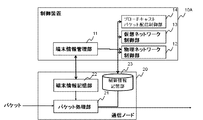
- control device 10 includes a terminal information management unit 11 that receives (acquires) and manages the terminal information from the communication node 20. Then, the control device 10 communicates a terminal connected to the control-target communication node based on a network configuration constituted by the communication node 20 and terminal information managed by the terminal information management unit. Is generated and set in the corresponding communication node (see FIGS. 3 and 4).
- control device 10 is configured to collect information on terminals connected to the communication node 20 and to set necessary control information based on the information.
- FIG. 2 is a diagram illustrating the configuration of the communication system according to the first embodiment of this invention.
- a configuration in which a control device 10A and a communication node 20 are connected via a control channel is shown.
- one communication node 20 is shown, but a plurality of communication nodes 20 may be provided.
- a plurality of control devices 10 may be arranged as necessary.
- the control device 10A includes a terminal information management unit 11, a physical network control unit 12, a virtual network control unit 13, and a broadcast packet distribution control unit 14. Note that such a control device 10A is based on the OpenFlow controller of Non-Patent Documents 1 and 2 including the physical network control unit 12, and the terminal information management unit 11, the virtual network control unit 13, and the broadcast packet distribution control unit. 14 and can be realized.
- the terminal information management unit 11 manages terminal information collected from a plurality of communication nodes.
- FIG. 3 is a diagram illustrating an example of terminal information collected from each of the communication nodes 20A to 20C in the control device 10A.
- the communication node 20A extracts terminal information including the position and address information of the terminal 30A from the packet received from the terminal 30A connected to the own device, and further associates the information with the learning time. And remember.
- the control device 10A collects information indicating that the terminal 30A is connected to the communication node 20A and its MAC address from the communication node 20A, and manages them by the terminal information management unit 11.
- the location of the terminal (connected communication node and its port) and the MAC address are managed.
- other VLAN IDs may be extracted and managed.
- the physical network control unit 12 refers to the topology information indicating the connection relationship of the communication nodes 20A to 20C and the terminal information managed by the terminal information management unit 11, and sets control information (set in the communication nodes 20A to 20C). Flow entry) is created and set in the corresponding communication nodes 20A to 20C.
- Control information is set as follows. First, the physical network control unit 12 calculates communication node 20A-communication node 20B as a packet transfer path between the terminal 30A and the terminal 30B. Next, the physical network control unit 12 creates and sets control information (flow entry) to be set in the communication nodes 20A and 20B on the route. Specifically, control information (flow entry) for outputting a packet addressed to the terminal 30B from the terminal 30A from the port P2 and transferring it to the communication node 20B is set in the communication node 20A.
- control information (flow entry) for outputting a packet addressed to the terminal 30B from the terminal 30A from the port P3 and transferring it to the terminal 30B is set in the communication node 20B.
- control information (flow entry) for transferring a backward packet addressed to the terminal 30A from the terminal 30B is also set.
- the virtual network control unit 13 has a function of virtually realizing a router or a bridge on the control device 10A, and performs layer 3 flow control that cannot be handled by the physical network control unit 12 (referred to as “second control unit”). Equivalent).
- the virtual network control unit 13 sets control information (flow entry) for L3 control triggered by an explicit request (reception of a packet-in message) from a communication node. Note that, in the control information for L3 control set here (flow entry; second control information), a higher priority than the control information set by the physical network control unit 12 is set. By doing so, it is possible to avoid contention between the control information set by the physical network control unit 12 and the control information for L3 control (second control information).
- the broadcast packet distribution control unit 14 has a function of setting control information (flow entry) for broadcast distribution in the communication nodes 20A to 20C.
- the communication nodes 20A to 20C include a packet processing unit 21, a terminal information storage unit 22, and a control information storage unit 23.
- the packet processing unit 21 refers to the control information storage unit 23, and if there is control information (flow entry) that matches the received packet, the processing (instruction field) defined in the control information (flow entry) ( Packet transfer etc.). In addition, the packet processing unit 21 extracts the terminal information of the unlearned terminal from the received packet and stores it in the terminal information storage unit 22 at the same time as performing the above processing. Note that such communication nodes 20A to 20C are based on the OpenFlow switch of Non-Patent Documents 1 and 2 including a packet processing unit 21 and a control information storage unit (corresponding to a flow table) 23. This can be realized by adding a terminal information learning function for an unlearned terminal and a function for suppressing a request for setting control information (flow entry).
- each unit (processing means) of the control device 10A and the communication nodes 20A to 20C shown in FIG. 2 is executed by a computer program that causes a computer mounted on these devices to execute the above-described processes using the hardware. It can also be realized.
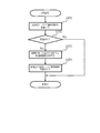
- FIG. 5 is a flowchart showing the operation of the communication node of the communication system according to the first exemplary embodiment of the present invention.
- the packet processing unit 21 of the communication node 20 refers to the control information storage unit 23 and matches the corresponding packet.
- the entry to be searched is searched (step S001).
- the packet processing unit 21 applies the processing (packet rewriting, forwarding, discarding, etc.) defined in the action field of the corresponding entry to the received packet ( Step S002).
- the packet processing unit 21 extracts terminal information (for example, MAC address, VLAN ID and connection port) from the received packet (step S004).
- terminal information for example, MAC address, VLAN ID and connection port
- the communication node of this embodiment immediately sends control information to the control device 10A even if there is no entry having a matching condition that matches the received packet in the control information storage unit 23. (Flow entry) setting request (packet in) is not performed.
- the packet processing unit 21 receives the packet if the packet is a broadcast packet (BC packet) (Yes in step S003).
- Terminal information is extracted from the packet (step S004).
- the broadcast packet is a learning target of terminal information even when matching control information (flow entry) exists. The reason is that it only matches the broadcast control information (flow entry) in the control information storage unit 23 and cannot be said to have learned the terminal information of the transmission source.
- the packet processing unit 21 checks whether or not an entry corresponding to the extracted terminal information already exists in the terminal information storage unit 22 (step S005).
- the packet processing unit 21 adds the corresponding terminal information to the terminal information storage unit 22 (step S006).
- the packet processing unit 21 confirms the last update time (most recent learning time) of the corresponding terminal information and calculates the difference from the current time (Ste S007).
- the packet processing unit 21 sends information on the packet to the control device 10A.
- Request (packet in) setting of control information (flow entry) for L3 (virtual network) (step S009).
- the predetermined threshold value is set to determine whether or not the communication is L3 communication that cannot be controlled by the L2 control information (flow entry) set when the terminal information is learned. Thereby, not only L2 communication but virtual network control by the virtual network control unit 13 is executed. For example, when the terminal information collection interval is 1 second, the same value (1 second) can be set as the predetermined threshold. This makes it possible to determine that a packet that does not conform to the existing control information (flow entry) has been received from a learned terminal.
- FIG. 6 is a flowchart showing the operation of the control device 10A of the communication system according to the first embodiment of this invention.
- the control device 10A periodically collects terminal information in the terminal information storage unit 22 of each communication node and stores it in the terminal information management unit 11 (step S101; control device of FIG. 3). (Refer to the balloon inside 10A).
- control device 10A uses the physical network control unit 12 to implement control information for realizing communication of the terminal corresponding to the updated terminal information. (Flow entry) is created (step S103).
- control device 10A sets the created control information (flow entry) in each communication node (step S104).
- the communication nodes (for example, the communication nodes 20A and 20B in FIG. 4) store the control information (flow entry) in the control information storage unit 23.
- control device 10A sets control information (flow entry) necessary for communication of a terminal connected to the communication node 20 without being triggered by a control information setting request (packet-in) from the communication node. . For this reason, even if traffic from a newly connected terminal is concentrated in a short time, the frequency of occurrence of packet-in messages or the like can be reduced. As a result, it is possible to reduce the load on the control device 10A and prevent the system from becoming unstable.
- the communication node 20 transmits the packet to the control device 10A and requests the setting of the control information for the virtual network, as before, for the packet that requires L3 control. (See step S009 in FIG. 5). For this reason, it is possible to coexist with a method of emulating a virtual network device by the control device 10A.
- the terminal information collection interval is a value that is tuned according to the hardware performance of the control device 10A and the communication node 20, the number of terminal information, the update frequency, and the like. Therefore, it is considered that a collection interval of about 1 second is appropriate.
- control information (flow entry) necessary for L2 packet transfer is set for all the updated terminals at the same time, the secure connection between the control device 10A and the communication node 20 is secured.
- Channel processing capability may be exceeded.
- the number of control information (flow entries) set per unit time according to the performance of the control device 10A and the communication node 20 such that one control device 10A has an upper limit of 1000 entries per second. It is also desirable to tune.
- the control device 10A has been described as collecting terminal information periodically, but the communication node 20 performs control at a predetermined trigger (a predetermined time interval, each time a new entry is detected). It is good also as a method of notifying terminal information to apparatus 10A. In particular, if the communication node 20 notifies the control device 10A of terminal information each time a new entry is detected, the control information (flow entry) can be set more quickly.
- the terminal position (port), the MAC address, and the VLAN ID are learned as the terminal information.
- the IP address may be learned as the terminal information.
- an ARP table can be generated from the terminal information.
- the communication node is Record the learning time of each terminal information, When the time when a packet is newly received from a terminal registered in the terminal information storage unit has passed a predetermined time from the learning time of the terminal information of the corresponding terminal, the packet is processed with respect to the control device.
- the communication system which requests the setting of the control information for.
- the control device In the communication system of the second form, The control device that has received the request for setting the control information for processing the packet has the second control applied with higher priority than the control information generated based on the network configuration and the terminal information terminal information.
- the communication node is The communication system which omits the process which extracts and memorize
- the communication system of the fourth form Even when the packet processing based on the control information set by the control device can be executed, if the received packet is a broadcast packet, terminal information including the location and address information of the terminal is extracted from the broadcast packet. Communication system.
- a terminal comprising a terminal information storage unit, and a computer comprising a connected control device, Processing to receive and manage the terminal information from the communication node to be controlled; Control information for realizing communication of a terminal connected to the communication node to be controlled based on the configuration of the network configured by the communication node to be controlled and the terminal information managed by the terminal information management unit Generating and setting the corresponding communication node;
- a program that executes It should be noted that the twelfth to fourteenth forms can be developed into the second to fifth forms as in the first form.
- control device 10A control device 20, 20A to 20C communication node 11 terminal information management unit 12 physical network control unit 12A control unit 13 virtual network control unit (second control unit) 14 broadcast packet distribution control unit 21 packet processing unit 22 terminal information storage unit 23 control information storage unit 30A to 30C terminal
Landscapes
- Engineering & Computer Science (AREA)
- Computer Networks & Wireless Communication (AREA)
- Signal Processing (AREA)
- Data Exchanges In Wide-Area Networks (AREA)
Abstract
本発明は、集中制御型ネットワークの制御装置の負荷を低減する。通信ノードは、制御装置から設定された制御情報に基づいて受信パケットを処理するパケット処理部と、自装置に接続されている端末から受信したパケットから、当該端末の位置とアドレス情報とを含む端末情報を抽出して記憶する端末情報記憶部と、を備える。制御装置は、制御対象の通信ノードから、前記端末情報を受信して管理する端末情報管理部と、前記制御対象の通信ノードによって構成されるネットワークの構成と、前記端末情報管理部にて管理されている端末情報とに基づいて、前記制御対象の通信ノードに接続する端末の通信を実現する制御情報を生成し、該当する通信ノードに設定する制御部と、を備える。
Description
(関連出願についての記載)
本発明は、日本国特許出願:特願2013-256978号(2013年12月12日出願)の優先権主張に基づくものであり、同出願の全記載内容は引用をもって本書に組み込み記載されているものとする。
本発明は、通信システム、通信ノード、制御装置、通信制御方法及びプログラムに関し、特に、制御装置が通信ノードを制御することにより通信を実現する通信システム、通信ノード、制御装置、通信制御方法及びプログラムに関する。
本発明は、日本国特許出願:特願2013-256978号(2013年12月12日出願)の優先権主張に基づくものであり、同出願の全記載内容は引用をもって本書に組み込み記載されているものとする。
本発明は、通信システム、通信ノード、制御装置、通信制御方法及びプログラムに関し、特に、制御装置が通信ノードを制御することにより通信を実現する通信システム、通信ノード、制御装置、通信制御方法及びプログラムに関する。
近年、オープンフローという技術が提案されている。オープンフローシステムでは、通信をエンドツーエンドのフローとして捉え、フロー単位で経路制御、障害回復、負荷分散、最適化を行う。オープンフロースイッチ(OFS)は、オープンフローコントローラ(OFC)との通信用のセキュアチャネルを備え、OFCから適宜追加または書き換え指示されるフローテーブルに従って動作する。フローテーブルには、フロー毎に、制御情報として、パケットヘッダと照合するマッチングルールとフロー統計情報と処理内容を定義したアクション(インストラクション)との組が定義される(非特許文献1、2参照)。
例えば、OFSは、パケットを受信すると、フローテーブルから、受信パケットのヘッダ情報に適合するマッチングルールを持つエントリを検索する。前記検索の結果、受信パケットに適合するエントリが見つかった場合、OFSは、フロー統計情報を更新するとともに、受信パケットに対して、当該エントリのアクションフィールドに記述された処理内容(指定ポートからのパケット送信、フラッディング、廃棄等)を実施する。一方、検索の結果、受信パケットに適合するエントリが見つからなかった場合、OFSは自力でパケット転送先を判断できないため、セキュアチャネルを介してOFCに対しパケット情報のコピーを転送する(オープンフロープロトコルのパケットインメッセージ)。
OFCはレイヤ2(L2)ネットワークの制御を行うこともできる。この場合、OFCはパケット情報の中から送信元MACアドレス、VLAN(Virtual Local Area Network) IDと接続ポートとを抽出し、MAC(Media Access Control)アドレステーブルを生成する。OFCは、生成したMACアドレステーブルに従い、OFSにL2パケットを転送するためのフローエントリを設定する。さらに、OFCは、MACアドレステーブルを検索し、宛先MACアドレスが存在する場合、OFSに対し、パケットインしたパケットのコピーを該当する物理ポートから出力するよう指示する(オープンフロープロトコルのパケットアウトメッセージ)。
上記したオープンフローでは、OFSから、大量のパケットインメッセージが送信されると、OFCが処理しきれず数分間パケットロスが発生したり、システム制御パケットまでロスして既存通信まで不安定になる可能性もある。このような大量のパケットインメッセージは、大量の端末が一斉に起動しGARP(Gratuitous Address Resolution Protocol)、DHCP(Dynamic Host Configuration Protocol)ディスカバリなどのブロードキャストパケットが一斉に送信された場合に起こりうる。また、スタティックARP(Address Resolution Protocol)などでARP解決済みの端末からOSパッチ更新やファイル同期などでユニキャストパケットが大量に送信された場合、ネットワーク機器やケーブル障害で運用中のサーバが接続されるOFSが切り替わった場合などにも起こりうる。
特許文献1には、OFCに対するフローエントリの問い合わせを低減することができるという技術が開示されている。具体的には、同文献記載のOFSは、OFCに対してフローエントリの問い合わせの実行後、OFCからフローエントリが設定されるまでの間、受信パケットをスタッキングし、スタッキングしたパケットを利用して同一フローのパケットの転送を制御(例えば、ブロードキャストする)する。
特許文献2にも、OFCに対してフローエントリの問い合わせを低減することができるという技術が開示されている。具体的には、同文献のOFCは、オープンフローネットワーク外にある仮想マシン管理システムから端末情報を入手することにより、フローエントリを設定する。
Nick McKeownほか7名、"OpenFlow: Enabling Innovation in Campus Networks"、[online]、[平成25(2013)年9月7日検索]、インターネット〈URL: http://www.openflow.org/documents/openflow-wp-latest.pdf〉
"OpenFlow Switch Specification" Version 1.1.0 Implemented (Wire Protocol 0x02)、[online]、[平成25(2013)年9月7日検索]、インターネット〈URL:http://www.openflow.org/documents/openflow-spec-v1.1.0.pdf〉
以下の分析は、本発明によって与えられたものである。特許文献1の方法では、同一のフローに属するパケットが連続してOFSに到着した場合に効果があるが、上述した同時多発的に発生するパケットインメッセージには対応できないという問題点がある。
また、特許文献2の方法も、仮想マシン管理システムに管理されている端末のみに有効な方法であり、その他のサーバやネットワーク機器では利用できないという問題点がある。
本発明は、上記したOFCに代表される集中制御型ネットワークにおいて通信ノードを制御する制御装置の負荷を低減できる通信システム、通信ノード、制御装置、通信制御方法及びプログラムを提供することを目的とする。
第1の視点によれば、制御装置から設定された制御情報に基づいて受信パケットを処理するパケット処理部と、自装置に接続されている端末から受信したパケットから抽出した、当該端末の位置とアドレス情報とを含む端末情報を記憶する端末情報記憶部と、を備える通信ノードと、制御対象の通信ノードから、前記端末情報を受信して管理する端末情報管理部と、前記制御対象の通信ノードによって構成されるネットワークの構成と、前記端末情報管理部にて管理されている端末情報とに基づいて、前記制御対象の通信ノードに接続する端末の通信を実現する制御情報を生成し、該当する通信ノードに設定する制御部と、を備える制御装置と、を含む通信システムが提供される。
第2の視点によれば、制御装置から設定された制御情報に基づいて受信パケットを処理するパケット処理部と、自装置に接続されている端末から受信したパケットから抽出した、当該端末の位置とアドレス情報とを含む端末情報を記憶する端末情報記憶部と、を備え、所定の契機で、前記制御装置に対して前記端末情報を送信する通信ノードが提供される。
第3の視点によれば、制御装置から設定された制御情報に基づいて受信パケットを処理するパケット処理部と、自装置に接続されている端末から受信したパケットから抽出した、当該端末の位置とアドレス情報とを含む端末情報を記憶する端末情報記憶部と、を備える通信ノードと、接続され、制御対象の通信ノードから、前記端末情報を受信して管理する端末情報管理部と、前記制御対象の通信ノードによって構成されるネットワークの構成と、前記端末情報管理部にて管理されている端末情報とに基づいて、前記制御対象の通信ノードに接続する端末の通信を実現する制御情報を生成し、該当する通信ノードに設定する制御部と、を備える制御装置が提供される。
第4の視点によれば、制御装置から設定された制御情報に基づいて受信パケットを処理するパケット処理部を備える通信ノードが、自装置に接続されている端末から受信したパケットから、当該端末の位置とアドレス情報とを含む端末情報を抽出して記憶するステップと、制御対象の通信ノードから、前記端末情報を受信して管理する端末情報管理部を備える制御装置が、前記制御対象の通信ノードによって構成されるネットワークの構成と、前記端末情報管理部にて管理されている端末情報とに基づいて、前記制御対象の通信ノードに接続する端末の通信を実現する制御情報を生成し、該当する通信ノードに設定するステップと、を含む通信制御方法が提供される。本方法は、通信ノードを制御する制御装置という、特定の機械に結びつけられている。
第5の視点によれば、上記した通信ノードの機能を実現するためのプログラムと、上記した制御装置の機能を実現するためのプログラムと、がそれぞれ提供される。なお、このプログラムは、コンピュータが読み取り可能な(非トランジエントな)記憶媒体に記録することができる。即ち、本発明は、コンピュータプログラム製品として具現することも可能である。
本発明によれば、集中制御型ネットワークにおいて通信ノードを制御する制御装置の負荷を低減することが可能となる。
はじめに本発明の一実施形態の概要について図面を参照して説明する。なお、この概要に付記した図面参照符号は、理解を助けるための一例として各要素に便宜上付記したものであり、本発明を図示の態様に限定することを意図するものではない。
本発明は、その一実施形態において、図1に示すように、制御装置10から設定された制御情報に基づいて受信パケットを処理するパケット処理部21を備える通信ノード20と、制御情報を生成し、該当する通信ノードに設定する制御部12Aを備える制御装置10と、を含む構成にて実現できる。
より具体的には、通信ノード20は、さらに、自装置に接続されている端末から受信したパケットから抽出した、当該端末の位置とアドレス情報とを含む端末情報を記憶する端末情報記憶部22を備える。また、通信ノード20は、パケット処理部21にて処理できないパケットを受信した場合であっても、直ちに、制御装置10に対し、制御情報の問い合わせを行わないよう設定されている。
また、制御装置10は、通信ノード20から、前記端末情報を受信(入手)して管理する端末情報管理部11を備える。そして、制御装置10は、前記通信ノード20によって構成されるネットワークの構成と、前記端末情報管理部にて管理されている端末情報とに基づいて、前記制御対象の通信ノードに接続する端末の通信を実現する制御情報を生成し、該当する通信ノードに設定する(図3、図4参照)。
以上のように通信ノードと制御装置をそれぞれ構成することにより、通信ノードからの問い合わせを契機とせずに、通信ノードに接続する端末の通信に必要な制御情報を設定することが可能となる。その理由は、通信ノード20に接続する端末の情報を収集させて、制御装置10がこれに基づいて、必要な制御情報を設定するよう構成したことにある。
[第1の実施形態]
続いて、本発明の第1の実施形態について図面を参照して詳細に説明する。図2は、本発明の第1の実施形態の通信システムの構成を示す図である。図2を参照すると、制御装置10Aと、通信ノード20とが制御用チャネルを介して接続された構成が示されている。なお、図2の例では、1台の通信ノード20が示されているが、通信ノード20は複数台あってもよい。同様に、必要に応じて、制御装置10が複数配置されていてもよい。
続いて、本発明の第1の実施形態について図面を参照して詳細に説明する。図2は、本発明の第1の実施形態の通信システムの構成を示す図である。図2を参照すると、制御装置10Aと、通信ノード20とが制御用チャネルを介して接続された構成が示されている。なお、図2の例では、1台の通信ノード20が示されているが、通信ノード20は複数台あってもよい。同様に、必要に応じて、制御装置10が複数配置されていてもよい。
制御装置10Aは、端末情報管理部11と、物理ネットワーク制御部12と、仮想ネットワーク制御部13と、ブロードキャストパケット配信制御部14とを備えている。なお、このような制御装置10Aは、物理ネットワーク制御部12を備える非特許文献1、2のオープンフローコントローラをベースに、端末情報管理部11と、仮想ネットワーク制御部13と、ブロードキャストパケット配信制御部14とを追加することで実現できる。
端末情報管理部11は、複数台の通信ノードから収集した端末情報を管理する。図3は、制御装置10Aにおいて、各通信ノード20A~20Cから収集した端末情報の一例を示す図である。図3の例では、通信ノード20Aは、自装置に接続されている端末30Aから受信したパケットから、端末30Aの位置とアドレス情報とを含む端末情報を抽出して、さらにその学習時刻と対応付けて記憶する。制御装置10Aは、通信ノード20Aから、通信ノード20Aに端末30Aが接続されているという情報と、そのMACアドレスとを収集し、端末情報管理部11にて管理する。なお、図3の例では、端末の位置(接続通信ノードとそのポート)と、MACアドレスを管理しているが、その他VLAN ID等も抽出して管理するようにしてもよい。
物理ネットワーク制御部12は、通信ノード20A~20Cの接続関係を示すトポロジ情報と、端末情報管理部11にて管理されている端末情報とを参照し、通信ノード20A~20Cに設定する制御情報(フローエントリ)を作成して、該当する通信ノード20A~20Cに設定する。
例えば、前記端末情報の収集の結果、図4に示すように、通信ノード20Aに接続されている端末30Aと、通信ノード20Bに接続されている端末30Bとの間の通信を実現する場合、次のように制御情報(フローエントリ)が設定される。まず、物理ネットワーク制御部12は、端末30Aと端末30B間のパケット転送経路として、通信ノード20A-通信ノード20Bを計算する。次に、物理ネットワーク制御部12は、経路上の通信ノード20A、20Bに設定する制御情報(フローエントリ)を作成し、設定する。具体的には、通信ノード20Aには、端末30Aから端末30B宛てのパケットをポートP2から出力し、通信ノード20Bに転送する制御情報(フローエントリ)が設定される。さらに、通信ノード20Bには、端末30Aから端末30B宛てのパケットをポートP3から出力し、端末30Bに転送する制御情報(フローエントリ)が設定される。なお、図4の例では、端末30Bから端末30A宛ての逆方向のパケットを転送するための制御情報(フローエントリ)も設定されている。
仮想ネットワーク制御部13は、制御装置10A上で仮想的にルータやブリッジを実現する機能を有し、物理ネットワーク制御部12では対応できないレイヤ3のフロー制御を行う(「第2の制御部」に相当)。本実施形態では、仮想ネットワーク制御部13は、通信ノードからの明示的要求(パケットインメッセージの受信)を契機として、L3制御用の制御情報(フローエントリ)を設定する。なお、ここで設定されるL3制御用の制御情報(フローエントリ;第2の制御情報)には、物理ネットワーク制御部12が設定した制御情報よりも高い優先度が設定される。このようにすることで、物理ネットワーク制御部12が設定した制御情報と、L3制御用の制御情報(第2の制御情報)との競合を回避することができる。
ブロードキャストパケット配信制御部14は、ブロードキャスト配信用の制御情報(フローエントリ)を通信ノード20A~20Cに設定する機能を備えている。
通信ノード20A~20Cは、パケット処理部21と、端末情報記憶部22と、制御情報記憶部23とを備えている。
パケット処理部21は、制御情報記憶部23を参照し、受信パケットに適合する制御情報(フローエントリ)がある場合はその制御情報(フローエントリ)のアクションフィールド(インストラクションフィールド)に定められた処理(パケット転送等)を実行する。また、パケット処理部21は、前記処理を行うと同時に、受信パケットから未学習の端末の端末情報を抽出して、端末情報記憶部22に保存する。なお、このような通信ノード20A~20Cは、パケット処理部21及び制御情報記憶部(フローテーブルに相当)23を備える非特許文献1、2のオープンフロースイッチをベースに、端末情報記憶部22と、未学習の端末の端末情報の学習機能と、制御情報(フローエントリ)の設定要求を抑止する機能と、を追加することで実現できる。
また、図2に示した制御装置10A及び通信ノード20A~20Cの各部(処理手段)は、これら装置に搭載されたコンピュータに、そのハードウェアを用いて、上記した各処理を実行させるコンピュータプログラムにより実現することもできる。
続いて、本実施形態の動作について図面を参照して詳細に説明する。図5は、本発明の第1の実施形態の通信システムの通信ノードの動作を表したフローチャートである。図5を参照すると、端末(例えば、図3、4の端末30A~30C)からパケットを受信した場合、通信ノード20のパケット処理部21は、制御情報記憶部23を参照し、該当パケットにマッチするエントリを検索する(ステップS001)。
前記検索の結果、マッチするエントリがある場合(ステップS001のYes)、パケット処理部21は、該当エントリのアクションフィールドに定義された処理(パケット書換え、転送、破棄等)を受信パケットに適用する(ステップS002)。
一方、前記検索の結果、マッチするエントリがない場合、パケット処理部21は受信したパケットから端末情報(例えば、MACアドレス、VLAN IDと接続ポート)を抽出する(ステップS004)。ここで、注意すべきは、本実施形態の通信ノードは、制御情報記憶部23に受信パケットに適合するマッチ条件を持つエントリが存在しない場合であっても、直ちに制御装置10Aに対し、制御情報(フローエントリ)の設定要求(パケットイン)を行わない点である。
また、ステップS001の検索の結果、受信パケットにマッチするエントリが見つかった場合であっても、当該パケットがブロードキャストパケット(BCパケット)である場合(ステップS003のYes)、パケット処理部21は受信したパケットから端末情報を抽出する(ステップS004)。このように、本実施形態では、ブロードキャストパケットについては、マッチする制御情報(フローエントリ)が存在する場合であっても、端末情報の学習対象としている。その理由は、制御情報記憶部23のブロードキャスト用の制御情報(フローエントリ)にマッチしているだけであり、送信元の端末情報を学習済みとは言い得ないからである。
次に、パケット処理部21は前記抽出した端末情報に対応するエントリが端末情報記憶部22に既に存在するか否かを確認する(ステップS005)。
端末情報記憶部22に該当する端末情報が存在しない場合、即ち、該当する端末の情報が未学習である場合、パケット処理部21は、該当する端末情報を端末情報記憶部22に追加する(ステップS006)。
一方、端末情報記憶部22に該当する端末情報が既に存在する場合、パケット処理部21は、該当する端末情報の最終更新時刻(直近学習時刻)を確認し、現時刻との差を計算する(ステップS007)。
次に、前記現時刻と最終更新時刻との差が、所定のしきい値を超えている場合(ステップS008のNo)、パケット処理部21は、制御装置10Aに対し、当該パケットの情報を送り、L3(仮想ネットワーク)用の制御情報(フローエントリ)の設定を要請(パケットイン)する(ステップS009)。前記所定のしきい値は、端末情報学習時に設定されるL2の制御情報(フローエントリ)では制御できないL3通信であるか否かを判定するために設定される。これにより、L2通信だけでなく、仮想ネットワーク制御部13による仮想ネットワーク制御が実行される。所定のしきい値としては、例えば、端末情報の収集間隔が1秒である場合、同じ値(1秒)を設定することができる。これにより、学習済みの端末から、既存の制御情報(フローエントリ)に適合しないパケットを受信したことを判別できるようになる。
続いて制御装置側の動作について説明する。図6は、本発明の第1の実施形態の通信システムの制御装置10Aの動作を表したフローチャートである。図6を参照すると、まず、制御装置10Aは、定期的に、各通信ノードの端末情報記憶部22の端末情報を収集し、端末情報管理部11に保存する(ステップS101;図3の制御装置10Aの吹き出し内参照)。
前記収集した端末情報に更新(異動)があった場合(ステップS102のYes)、制御装置10Aは、物理ネットワーク制御部12により、更新のあった端末情報に対応する端末の通信を実現する制御情報(フローエントリ)を作成する(ステップS103)。
さらに、制御装置10Aは、各通信ノードに、前記作成した制御情報(フローエントリ)を設定する(ステップS104)。通信ノード(例えば、図4の通信ノード20A、20B)は、前記制御情報(フローエントリ)を制御情報記憶部23に記憶する。
以上のように制御装置10Aは、通信ノードからの制御情報の設定要求(パケットイン)を契機とせずに、通信ノード20に接続してきた端末の通信に必要な制御情報(フローエントリ)を設定する。このため、新規の接続してきた端末からのトラフィックが短時間に集中発生しても、パケットインメッセージ等の発生頻度を減らすことができる。結果として、制御装置10Aの負荷を低減し、システムが不安定になることを防止できる。
また、上記した第1の実施形態の通信ノード20は、L3制御が必要なパケットについては、これまでどおり、制御装置10Aに対し、該当パケットを送信し、仮想ネットワーク用の制御情報の設定を要請する(図5のステップS009参照)。このため、制御装置10Aにより仮想的なネットワーク機器をエミュレーションする方法とも併存可能である。
なお、上記した実施形態では、新規接続端末からのパケット受信を契機とするパケットインによるリアルタイムな端末情報の学習とパケットアウトによるパケット転送は行わないため、端末情報の収集と制御情報(フローエントリ)の設定が完了するまでの間、未学習のパケットは転送できず捨てられてしまう。このため、端末情報の収集間隔は可能な限り短いことが望まれる。端末情報の収集間隔は、制御装置10Aと通信ノード20のハード性能や端末情報の数や更新頻度等に応じてチューニングされる値であるが、一般的なハード性能と実用上問題となりにくい学習時間を考えると、収集間隔は1秒間隔程度が適当と考えられる。
また本実施形態では、例えば、経路変更などにより端末が接続される通信ノードが移動した場合、広く普及している高速スパニングツリーと同様に数秒程度、パケット転送できない時間が発生するが、TCP(Transmission Control Protocol)など上位層の再送処理により救われるため実用上問題は発生しにくい。
また、多数の端末情報が一斉に更新された際に、更新された端末すべてについて同時にL2パケット転送に必要な制御情報(フローエントリ)の設定を行うと、制御装置10Aと通信ノード20間のセキュアチャンネル処理能力をオーバーする可能性がある。このため、例えば1台の制御装置10Aが、1秒当たりに1000エントリを上限とするなど、制御装置10Aと通信ノード20の性能に合わせて、単位時間あたりの制御情報(フローエントリ)の設定数をチューニングすることも望ましい。
以上、本発明の各実施形態を説明したが、本発明は、上記した実施形態に限定されるものではなく、本発明の基本的技術的思想を逸脱しない範囲で、更なる変形・置換・調整を加えることができる。例えば、各図面に示したネットワーク構成や要素の構成は、本発明の理解を助けるための一例であり、これらの図面に示した構成に限定されるものではない。
また例えば、上記した実施形態では、制御装置10Aが、端末情報を定期的に収集するものとして説明したが、通信ノード20が、所定の契機(所定時間間隔、新規エントリ検出の都度)で、制御装置10Aに端末情報を通知する方法としてもよい。とりわけ、新規エントリ検出の都度、通信ノード20が、制御装置10Aに端末情報を通知することとすれば、制御情報(フローエントリ)をより速やかに設定できることになる。
また例えば、上記した実施形態では、端末情報として、端末の位置(ポート)、MACアドレス及びVLAN IDを学習するものとして説明したが、端末情報としてIPアドレスも学習してもよい。この場合、端末情報からARPテーブルを生成することも可能となる。
最後に、本発明の好ましい形態を要約する。
[第1の形態]
(上記第1の視点による通信システム参照)
[第2の形態]
第1の形態の通信システムにおいて、
前記通信ノードは、
各端末情報の学習時刻を記録し、
前記端末情報記憶部に登録済みの端末から新規にパケットを受信した時刻が、該当端末の端末情報の学習時刻から、所定時間経過している場合、前記制御装置に対して、前記パケットを処理するための制御情報の設定を依頼する通信システム。
[第3の形態]
第2の形態の通信システムにおいて、
前記パケットを処理するための制御情報の設定の依頼を受けた制御装置は、前記ネットワークの構成と前記端末情報端末情報とに基づいて生成した制御情報よりも高優先に適用される第2の制御情報を生成し、該当する通信ノードに設定する通信システム。
[第4の形態]
第1~第3いずれか一の形態の通信システムにおいて、
前記通信ノードは、
前記制御装置から設定された制御情報によるパケット処理を実行できた場合、前記パケットから、当該端末の位置とアドレス情報とを含む端末情報を抽出して記憶する処理を省略する通信システム。
[第5の形態]
第4の形態の通信システムにおいて、
前記制御装置から設定された制御情報によるパケット処理を実行できた場合であっても、受信パケットがブロードキャストパケットである場合、前記ブロードキャストパケットから、当該端末の位置とアドレス情報とを含む端末情報を抽出して記憶する通信システム。
[第6の形態]
(上記第2の視点による通信ノード参照)
[第7の形態]
第6の形態の通信ノードにおいて、
各端末情報の学習時刻を記録し、
前記端末情報記憶部にて管理している端末から新規にパケットを受信した時刻が、該当端末の端末情報の学習時刻から、所定時間経過している場合、前記制御装置に対して、前記パケットを処理するための制御情報の設定を依頼する通信ノード。
[第8の形態]
第6又は第7の形態の通信ノードにおいて、
前記制御装置から設定された制御情報によるパケット処理を実行できた場合、前記パケットから、当該端末の位置とアドレス情報とを含む端末情報を抽出して記憶する処理を省略する通信ノード。
[第9の形態]
第8の形態の通信ノードにおいて、
前記制御装置から設定された制御情報によるパケット処理を実行できた場合であっても、受信パケットがブロードキャストパケットである場合、前記ブロードキャストパケットから、当該端末の位置とアドレス情報とを含む端末情報を抽出して記憶する通信ノード。
[第10の形態]
(上記第3の視点による制御装置参照)
[第11の形態]
第10の形態の制御装置において、
前記通信ノードから、パケットを処理するための制御情報の設定の依頼を受けた場合、前記ネットワークの構成と前記端末情報端末情報とに基づいて生成した制御情報よりも高優先に適用される第2の制御情報を生成し、該当する通信ノードに設定する第2の制御部を備える制御装置。
[第12の形態]
(上記第4の視点による通信制御方法参照)
[第13の形態]
制御装置から設定された制御情報に基づいて受信パケットを処理するパケット処理部を備えた通信ノードに搭載されたコンピュータに、
自装置に接続されている端末から受信したパケットから、当該端末の位置とアドレス情報とを含む端末情報を抽出して記憶する処理と、
所定の契機で、前記制御装置に対して前記端末情報を送信する処理とを実行させるプログラム。
[第14の形態]
制御装置から設定された制御情報に基づいて受信パケットを処理するパケット処理部と、自装置に接続されている端末から受信したパケットから、当該端末の位置とアドレス情報とを含む端末情報を抽出して記憶する端末情報記憶部と、を備える通信ノードと、接続された制御装置を構成するコンピュータに、
制御対象の通信ノードから、前記端末情報を受信して管理する処理と、
前記制御対象の通信ノードによって構成されるネットワークの構成と、前記端末情報管理部にて管理されている端末情報とに基づいて、前記制御対象の通信ノードに接続する端末の通信を実現する制御情報を生成し、該当する通信ノードに設定する処理と、
を実行させるプログラム。
なお、上記第12~第14の形態は、第1の形態と同様に、第2~第5の形態に展開することが可能である。
[第1の形態]
(上記第1の視点による通信システム参照)
[第2の形態]
第1の形態の通信システムにおいて、
前記通信ノードは、
各端末情報の学習時刻を記録し、
前記端末情報記憶部に登録済みの端末から新規にパケットを受信した時刻が、該当端末の端末情報の学習時刻から、所定時間経過している場合、前記制御装置に対して、前記パケットを処理するための制御情報の設定を依頼する通信システム。
[第3の形態]
第2の形態の通信システムにおいて、
前記パケットを処理するための制御情報の設定の依頼を受けた制御装置は、前記ネットワークの構成と前記端末情報端末情報とに基づいて生成した制御情報よりも高優先に適用される第2の制御情報を生成し、該当する通信ノードに設定する通信システム。
[第4の形態]
第1~第3いずれか一の形態の通信システムにおいて、
前記通信ノードは、
前記制御装置から設定された制御情報によるパケット処理を実行できた場合、前記パケットから、当該端末の位置とアドレス情報とを含む端末情報を抽出して記憶する処理を省略する通信システム。
[第5の形態]
第4の形態の通信システムにおいて、
前記制御装置から設定された制御情報によるパケット処理を実行できた場合であっても、受信パケットがブロードキャストパケットである場合、前記ブロードキャストパケットから、当該端末の位置とアドレス情報とを含む端末情報を抽出して記憶する通信システム。
[第6の形態]
(上記第2の視点による通信ノード参照)
[第7の形態]
第6の形態の通信ノードにおいて、
各端末情報の学習時刻を記録し、
前記端末情報記憶部にて管理している端末から新規にパケットを受信した時刻が、該当端末の端末情報の学習時刻から、所定時間経過している場合、前記制御装置に対して、前記パケットを処理するための制御情報の設定を依頼する通信ノード。
[第8の形態]
第6又は第7の形態の通信ノードにおいて、
前記制御装置から設定された制御情報によるパケット処理を実行できた場合、前記パケットから、当該端末の位置とアドレス情報とを含む端末情報を抽出して記憶する処理を省略する通信ノード。
[第9の形態]
第8の形態の通信ノードにおいて、
前記制御装置から設定された制御情報によるパケット処理を実行できた場合であっても、受信パケットがブロードキャストパケットである場合、前記ブロードキャストパケットから、当該端末の位置とアドレス情報とを含む端末情報を抽出して記憶する通信ノード。
[第10の形態]
(上記第3の視点による制御装置参照)
[第11の形態]
第10の形態の制御装置において、
前記通信ノードから、パケットを処理するための制御情報の設定の依頼を受けた場合、前記ネットワークの構成と前記端末情報端末情報とに基づいて生成した制御情報よりも高優先に適用される第2の制御情報を生成し、該当する通信ノードに設定する第2の制御部を備える制御装置。
[第12の形態]
(上記第4の視点による通信制御方法参照)
[第13の形態]
制御装置から設定された制御情報に基づいて受信パケットを処理するパケット処理部を備えた通信ノードに搭載されたコンピュータに、
自装置に接続されている端末から受信したパケットから、当該端末の位置とアドレス情報とを含む端末情報を抽出して記憶する処理と、
所定の契機で、前記制御装置に対して前記端末情報を送信する処理とを実行させるプログラム。
[第14の形態]
制御装置から設定された制御情報に基づいて受信パケットを処理するパケット処理部と、自装置に接続されている端末から受信したパケットから、当該端末の位置とアドレス情報とを含む端末情報を抽出して記憶する端末情報記憶部と、を備える通信ノードと、接続された制御装置を構成するコンピュータに、
制御対象の通信ノードから、前記端末情報を受信して管理する処理と、
前記制御対象の通信ノードによって構成されるネットワークの構成と、前記端末情報管理部にて管理されている端末情報とに基づいて、前記制御対象の通信ノードに接続する端末の通信を実現する制御情報を生成し、該当する通信ノードに設定する処理と、
を実行させるプログラム。
なお、上記第12~第14の形態は、第1の形態と同様に、第2~第5の形態に展開することが可能である。
なお、上記の特許文献および非特許文献の各開示を、本書に引用をもって繰り込むものとする。本発明の全開示(請求の範囲を含む)の枠内において、さらにその基本的技術思想に基づいて、実施形態ないし実施例の変更・調整が可能である。また、本発明の請求の範囲の枠内において種々の開示要素(各請求項の各要素、各実施形態ないし実施例の各要素、各図面の各要素等を含む)の多様な組み合わせ、ないし選択が可能である。すなわち、本発明は、請求の範囲を含む全開示、技術的思想にしたがって当業者であればなし得るであろう各種変形、修正を含むことは勿論である。特に、本書に記載した数値範囲については、当該範囲内に含まれる任意の数値ないし小範囲が、別段の記載のない場合でも具体的に記載されているものと解釈されるべきである。
10、10A 制御装置
20、20A~20C 通信ノード
11 端末情報管理部
12 物理ネットワーク制御部
12A 制御部
13 仮想ネットワーク制御部(第2の制御部)
14 ブロードキャストパケット配信制御部
21 パケット処理部
22 端末情報記憶部
23 制御情報記憶部
30A~30C 端末
20、20A~20C 通信ノード
11 端末情報管理部
12 物理ネットワーク制御部
12A 制御部
13 仮想ネットワーク制御部(第2の制御部)
14 ブロードキャストパケット配信制御部
21 パケット処理部
22 端末情報記憶部
23 制御情報記憶部
30A~30C 端末
Claims (10)
- 制御装置から設定された制御情報に基づいて受信パケットを処理するパケット処理部と、自装置に接続されている端末から受信したパケットから、当該端末の位置とアドレス情報とを含む端末情報を抽出して記憶する端末情報記憶部と、を備える通信ノードと、
制御対象の通信ノードから、前記端末情報を受信して管理する端末情報管理部と、
前記制御対象の通信ノードによって構成されるネットワークの構成と、前記端末情報管理部にて管理されている端末情報とに基づいて、前記制御対象の通信ノードに接続する端末の通信を実現する制御情報を生成し、該当する通信ノードに設定する制御部と、
を備える制御装置と、を含む通信システム。 - 前記通信ノードは、
各端末情報の学習時刻を記録し、
前記端末情報記憶部に登録済みの端末から新規にパケットを受信した時刻が、該当端末の端末情報の学習時刻から、所定時間経過している場合、前記制御装置に対して、前記パケットを処理するための制御情報の設定を依頼する請求項1の通信システム。 - 前記通信ノードは、
前記制御装置から設定された制御情報によるパケット処理を実行できた場合、前記パケットから、当該端末の位置とアドレス情報とを含む端末情報を抽出して記憶する処理を省略する請求項1又は2の通信システム。 - 前記制御装置から設定された制御情報によるパケット処理を実行できた場合であっても、受信パケットがブロードキャストパケットである場合、前記ブロードキャストパケットから、当該端末の位置とアドレス情報とを含む端末情報を抽出して記憶する請求項3の通信システム。
- 制御装置から設定された制御情報に基づいて受信パケットを処理するパケット処理部と、自装置に接続されている端末から受信したパケットから、当該端末の位置とアドレス情報とを含む端末情報を抽出して記憶する端末情報記憶部と、を備え、
所定の契機で、前記制御装置に対して前記端末情報を送信する通信ノード。 - 各端末情報の学習時刻を記録し、
前記端末情報記憶部にて管理している端末から新規にパケットを受信した時刻が、該当端末の端末情報の学習時刻から、所定時間経過している場合、前記制御装置に対して、前記パケットを処理するための制御情報の設定を依頼する請求項5の通信ノード。 - 前記制御装置から設定された制御情報によるパケット処理を実行できた場合、前記パケットから、当該端末の位置とアドレス情報とを含む端末情報を抽出して記憶する処理を省略する請求項5又は6の通信ノード。
- 前記制御装置から設定された制御情報によるパケット処理を実行できた場合であっても、受信パケットがブロードキャストパケットである場合、前記ブロードキャストパケットから、当該端末の位置とアドレス情報とを含む端末情報を抽出して記憶する請求項7の通信ノード。
- 制御装置から設定された制御情報に基づいて受信パケットを処理するパケット処理部と、自装置に接続されている端末から受信したパケットから、当該端末の位置とアドレス情報とを含む端末情報を抽出して記憶する端末情報記憶部と、を備える通信ノードと、接続され、
制御対象の通信ノードから、前記端末情報を受信して管理する端末情報管理部と、
前記制御対象の通信ノードによって構成されるネットワークの構成と、前記端末情報管理部にて管理されている端末情報とに基づいて、前記制御対象の通信ノードに接続する端末の通信を実現する制御情報を生成し、該当する通信ノードに設定する制御部と、
を備える制御装置。 - 制御装置から設定された制御情報に基づいて受信パケットを処理するパケット処理部を備える通信ノードが、自装置に接続されている端末から受信したパケットから、当該端末の位置とアドレス情報とを含む端末情報を抽出して記憶するステップと、
制御対象の通信ノードから、前記端末情報を受信して管理する端末情報管理部を備える制御装置が、
前記制御対象の通信ノードによって構成されるネットワークの構成と、前記端末情報管理部にて管理されている端末情報とに基づいて、前記制御対象の通信ノードに接続する端末の通信を実現する制御情報を生成し、該当する通信ノードに設定するステップと、
を含む通信制御方法。
Applications Claiming Priority (2)
| Application Number | Priority Date | Filing Date | Title |
|---|---|---|---|
| JP2013256978 | 2013-12-12 | ||
| JP2013-256978 | 2013-12-12 |
Publications (1)
| Publication Number | Publication Date |
|---|---|
| WO2015087947A1 true WO2015087947A1 (ja) | 2015-06-18 |
Family
ID=53371246
Family Applications (1)
| Application Number | Title | Priority Date | Filing Date |
|---|---|---|---|
| PCT/JP2014/082775 Ceased WO2015087947A1 (ja) | 2013-12-12 | 2014-12-11 | 通信システム、通信ノード、制御装置、通信制御方法及びプログラム |
Country Status (1)
| Country | Link |
|---|---|
| WO (1) | WO2015087947A1 (ja) |
Citations (1)
| Publication number | Priority date | Publication date | Assignee | Title |
|---|---|---|---|---|
| JP2013175996A (ja) * | 2012-02-27 | 2013-09-05 | Hitachi Ltd | 管理計算機、転送経路管理方法及び計算機システム |
-
2014
- 2014-12-11 WO PCT/JP2014/082775 patent/WO2015087947A1/ja not_active Ceased
Patent Citations (1)
| Publication number | Priority date | Publication date | Assignee | Title |
|---|---|---|---|---|
| JP2013175996A (ja) * | 2012-02-27 | 2013-09-05 | Hitachi Ltd | 管理計算機、転送経路管理方法及び計算機システム |
Non-Patent Citations (1)
| Title |
|---|
| DAISUKE KOTANI ET AL.: "A Method of Controlling Packet-In Messages in OpenFlow Switches for Reducing Loads of Switches and Control Networks", IEICE TECHNICAL REPORT, vol. 112, no. 212, 14 September 2012 (2012-09-14), pages 31 - 36 * |
Similar Documents
| Publication | Publication Date | Title |
|---|---|---|
| JP6418261B2 (ja) | 通信システム、ノード、制御装置、通信方法及びプログラム | |
| JP5994851B2 (ja) | 転送装置の制御装置、転送装置の制御方法、通信システムおよびプログラム | |
| JP5880560B2 (ja) | 通信システム、転送ノード、受信パケット処理方法およびプログラム | |
| WO2012070173A1 (en) | Communication system, communication device, controller, and method and program for controlling forwarding path of packet flow | |
| WO2012133290A1 (ja) | コンピュータシステム、及び通信方法 | |
| KR20130032314A (ko) | 통신 시스템, 노드, 제어 장치, 통신 방법 및 프로그램 | |
| WO2011162215A1 (ja) | 通信システム、制御装置、ノードの制御方法およびプログラム | |
| JP5858141B2 (ja) | 制御装置、通信装置、通信システム、通信方法及びプログラム | |
| WO2014017631A1 (ja) | 制御装置、通信システム、通信方法及びプログラム | |
| WO2014129624A1 (ja) | 制御装置、通信システム、経路切替方法及びプログラム | |
| US20190007279A1 (en) | Control apparatus, communication system, virtual network management method, and program | |
| WO2014175335A1 (ja) | 制御装置、計算機システム、通信制御方法及びプログラム | |
| JP5991427B2 (ja) | 制御装置、通信システム、制御情報の送信方法及びプログラム | |
| JP6187466B2 (ja) | 制御装置、通信システム、通信方法及びプログラム | |
| WO2015087947A1 (ja) | 通信システム、通信ノード、制御装置、通信制御方法及びプログラム | |
| JP2016139908A (ja) | 通信システム、通信ノード、制御装置、通信制御方法、及び、プログラム | |
| JP5861424B2 (ja) | 通信システム、制御装置、通信方法およびプログラム | |
| JP5768600B2 (ja) | 通信システム、制御装置、パケット転送方法およびプログラム | |
| WO2014010724A1 (ja) | 制御装置、通信システム、通信方法及びプログラム | |
| JP6365663B2 (ja) | 通信装置、制御装置、通信システム、受信パケットの処理方法、通信装置の制御方法及びプログラム | |
| WO2014142256A1 (ja) | 通信システム、制御装置、通信方法およびプログラム | |
| WO2014142081A1 (ja) | 転送ノード、制御装置、通信システム、パケット処理方法及びプログラム | |
| JP2015128213A (ja) | 通信ノード、制御装置、通信システム、通信方法及びプログラム |
Legal Events
| Date | Code | Title | Description |
|---|---|---|---|
| 121 | Ep: the epo has been informed by wipo that ep was designated in this application |
Ref document number: 14870210 Country of ref document: EP Kind code of ref document: A1 |
|
| NENP | Non-entry into the national phase |
Ref country code: DE |
|
| 122 | Ep: pct application non-entry in european phase |
Ref document number: 14870210 Country of ref document: EP Kind code of ref document: A1 |
|
| NENP | Non-entry into the national phase |
Ref country code: JP |