WO2015087685A1 - 基地局装置、端末装置、送信方法及び受信方法 - Google Patents
基地局装置、端末装置、送信方法及び受信方法 Download PDFInfo
- Publication number
- WO2015087685A1 WO2015087685A1 PCT/JP2014/080824 JP2014080824W WO2015087685A1 WO 2015087685 A1 WO2015087685 A1 WO 2015087685A1 JP 2014080824 W JP2014080824 W JP 2014080824W WO 2015087685 A1 WO2015087685 A1 WO 2015087685A1
- Authority
- WO
- WIPO (PCT)
- Prior art keywords
- base station
- station apparatus
- terminal device
- code
- receiving antenna
- Prior art date
- Legal status (The legal status is an assumption and is not a legal conclusion. Google has not performed a legal analysis and makes no representation as to the accuracy of the status listed.)
- Ceased
Links
Images



Classifications
-
- H—ELECTRICITY
- H04—ELECTRIC COMMUNICATION TECHNIQUE
- H04B—TRANSMISSION
- H04B7/00—Radio transmission systems, i.e. using radiation field
- H04B7/02—Diversity systems; Multi-antenna system, i.e. transmission or reception using multiple antennas
- H04B7/04—Diversity systems; Multi-antenna system, i.e. transmission or reception using multiple antennas using two or more spaced independent antennas
- H04B7/0413—MIMO systems
- H04B7/0456—Selection of precoding matrices or codebooks, e.g. using matrices antenna weighting
-
- H—ELECTRICITY
- H04—ELECTRIC COMMUNICATION TECHNIQUE
- H04B—TRANSMISSION
- H04B7/00—Radio transmission systems, i.e. using radiation field
- H04B7/02—Diversity systems; Multi-antenna system, i.e. transmission or reception using multiple antennas
- H04B7/04—Diversity systems; Multi-antenna system, i.e. transmission or reception using multiple antennas using two or more spaced independent antennas
- H04B7/0413—MIMO systems
-
- H—ELECTRICITY
- H04—ELECTRIC COMMUNICATION TECHNIQUE
- H04B—TRANSMISSION
- H04B7/00—Radio transmission systems, i.e. using radiation field
- H04B7/02—Diversity systems; Multi-antenna system, i.e. transmission or reception using multiple antennas
- H04B7/04—Diversity systems; Multi-antenna system, i.e. transmission or reception using multiple antennas using two or more spaced independent antennas
- H04B7/06—Diversity systems; Multi-antenna system, i.e. transmission or reception using multiple antennas using two or more spaced independent antennas at the transmitting station
- H04B7/0613—Diversity systems; Multi-antenna system, i.e. transmission or reception using multiple antennas using two or more spaced independent antennas at the transmitting station using simultaneous transmission
- H04B7/0678—Diversity systems; Multi-antenna system, i.e. transmission or reception using multiple antennas using two or more spaced independent antennas at the transmitting station using simultaneous transmission using different spreading codes between antennas
-
- H—ELECTRICITY
- H04—ELECTRIC COMMUNICATION TECHNIQUE
- H04L—TRANSMISSION OF DIGITAL INFORMATION, e.g. TELEGRAPHIC COMMUNICATION
- H04L5/00—Arrangements affording multiple use of the transmission path
- H04L5/0001—Arrangements for dividing the transmission path
- H04L5/0003—Two-dimensional division
- H04L5/0005—Time-frequency
- H04L5/0007—Time-frequency the frequencies being orthogonal, e.g. OFDM(A) or DMT
-
- H—ELECTRICITY
- H04—ELECTRIC COMMUNICATION TECHNIQUE
- H04L—TRANSMISSION OF DIGITAL INFORMATION, e.g. TELEGRAPHIC COMMUNICATION
- H04L5/00—Arrangements affording multiple use of the transmission path
- H04L5/0001—Arrangements for dividing the transmission path
- H04L5/0026—Division using four or more dimensions, e.g. beam steering or quasi-co-location [QCL]
-
- H—ELECTRICITY
- H04—ELECTRIC COMMUNICATION TECHNIQUE
- H04L—TRANSMISSION OF DIGITAL INFORMATION, e.g. TELEGRAPHIC COMMUNICATION
- H04L5/00—Arrangements affording multiple use of the transmission path
- H04L5/0001—Arrangements for dividing the transmission path
- H04L5/0028—Variable division
-
- H—ELECTRICITY
- H04—ELECTRIC COMMUNICATION TECHNIQUE
- H04L—TRANSMISSION OF DIGITAL INFORMATION, e.g. TELEGRAPHIC COMMUNICATION
- H04L5/00—Arrangements affording multiple use of the transmission path
- H04L5/0091—Signalling for the administration of the divided path, e.g. signalling of configuration information
- H04L5/0092—Indication of how the channel is divided
-
- H—ELECTRICITY
- H04—ELECTRIC COMMUNICATION TECHNIQUE
- H04B—TRANSMISSION
- H04B7/00—Radio transmission systems, i.e. using radiation field
- H04B7/02—Diversity systems; Multi-antenna system, i.e. transmission or reception using multiple antennas
- H04B7/10—Polarisation diversity; Directional diversity
Definitions
- the present invention relates to a base station device, a terminal device, a transmission method, and a reception method.
- MIMO Multiple Input Multiple Multiple Output
- LTE Long Term Evolution
- wireless LAN Local (Area Network)
- MIMO transmission with a greatly increased number of antennas has attracted attention.
- Such a MIMO transmission is called Massive MIMO, Large Scale MIMO, Full Dimension MIMO, or the like.
- the MIMO channel matrix is H
- the gain for the desired signal and the gain for the interference signal can be obtained only by using HH as the precoding matrix. Since a large difference occurs, it is possible to suppress interference very easily.
- Massive MIMO is described in Non-Patent Document 1.
- Non-Patent Document 1 is effective only when the number of transmission antennas is very large compared to the number of reception antennas.
- the desired signal and the interference signal There is a problem that the transmission characteristic deteriorates because the gain difference between the two becomes small.
- the present invention has been made in view of such circumstances, and an object of the present invention is to provide a base station apparatus and terminal capable of obtaining good transmission characteristics even when the difference between the number of transmitting antennas and the number of receiving antennas is small.
- An apparatus, a transmission method, and a reception method are provided.
- the configurations of the base station apparatus and terminal apparatus according to the present invention are as follows.
- the base station apparatus of the present invention is characterized in that the modulation symbol is spread and code-multiplexed in the direction of the receiving antenna of the terminal apparatus, precoded and transmitted.
- the spreading factor of the spreading code for spreading in the direction of the receiving antenna is the number of receiving antennas of the terminal apparatus.
- the base station apparatus of the present invention is characterized in that the code multiplexing number is determined based on information indicating the code multiplexing number fed back from the terminal apparatus.
- the precoding weight matrix is selected from a preset codebook.
- transmission is performed using a plurality of polarization antennas.
- the base station apparatus of the present invention is characterized by spreading in the time direction in addition to the receiving antenna direction.
- the base station apparatus of the present invention is characterized by spreading in the frequency direction in addition to the receiving antenna direction.
- the terminal device of the present invention includes a despreading unit that despreads the received signal received by each receiving antenna in the direction of the receiving antenna.
- the terminal device of the present invention is characterized in that information indicating the number of multiplexed codes is fed back to the base station device.
- a precoding matrix is selected from a code book for each reception antenna, and information indicating the precoding matrix is fed back to the base station apparatus.
- the terminal device of the present invention is characterized by comprising a plurality of polarization antennas and despreading in the direction of the polarization antennas.
- the transmission method of the present invention is characterized in that the modulation symbol is spread and code-multiplexed in the direction of the reception antenna of the terminal device, and is precoded and transmitted.
- the reception method of the present invention includes a despreading step of despreading a reception signal received by each reception antenna in the direction of the reception antenna.
- spreading code multiplexing is performed in the direction of the receiving antenna. Therefore, by changing the multiplexing number, it is possible to obtain good transmission characteristics even when the difference between the number of transmitting antennas and the number of receiving antennas is small.
- the communication system in the embodiment includes a base station device (transmitting device, cell, transmission point, transmitting antenna group, transmitting antenna port group, component carrier, eNodeB) and terminal device (mobile terminal, receiving point, receiving terminal, receiving device, receiving) Antenna group, receiving antenna port group, User Equipment).
- base station device transmitting device, cell, transmission point, transmitting antenna group, transmitting antenna port group, component carrier, eNodeB
- terminal device mobile terminal, receiving point, receiving terminal, receiving device, receiving
- Antenna group, receiving antenna port group, User Equipment User Equipment
- downlink is described, but the present invention is not limited to this, and is also applicable to uplink.
- OFDM Orthogonal Frequency Division Multiplexing
- the present invention is not limited to this and is also applied to other systems such as single carrier transmission. Is possible.
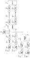
- FIG. 1 is a schematic block diagram showing a configuration of a base station apparatus in the present embodiment.
- the base station apparatus includes an upper layer 101, encoding units 102-1 to 102-U, scrambling units 103-1 to 103-U, modulation units 104-1 to 104-U, a layer mapping unit 105, a code multiplexing unit 106, Precoding section 107, reference signal generation section 108, resource mapping section 109, OFDM signal generation sections 110-1 to 110-T, radio transmission sections 111-1 to 111-T, and transmission antennas 112-1 to 112-T are provided.
- U represents the number of code words.
- T represents the number of transmission antennas.
- a chip control circuit that controls each functional block is provided.
- the upper layer 101 is a layer of functions higher than the physical layer (Physical Layer) among the layers of communication functions defined in the OSI reference model, such as a MAC (Media Access Control) layer, a data link layer, Network layer and the like.
- the higher layer 101 also notifies other parameters necessary for each part of the base station apparatus to perform its function.
- the encoding units 102-1 to 102-U perform error correction encoding on the information data input from the upper layer 101, and generate encoded bits (also referred to as code words).
- the information data is, for example, an audio signal accompanying a call, a still image or moving image signal representing a captured image, a character message, or the like.
- the encoding methods used when the encoding units 102-1 to 102-U perform error correction encoding are, for example, turbo encoding (Turbo Coding), convolutional encoding (Convolutional Coding), and low density parity check encoding ( Low Density Parity Check coding (LDPC).
- the encoding units 102-1 to 102-U perform encoding on the encoded bit sequence in order to match the coding rate of the error correction encoded data sequence with the encoding rate corresponding to the data transmission rate. Rate matching processing may be performed. Further, the encoding units 102-1 to 102-U may have a function of rearranging and interleaving the error correction encoded data series.
- the scramblers 103-1 to 103-U scramble each codeword based on the cell ID.
- the scrambled codeword is mapped to a modulation symbol in the modulation units 104-1 to 104-U.
- Modulating sections 104-1 to 104-U may have a function of rearranging generated modulation symbols and interleaving them.
- the modulation symbol is layer mapped in the layer mapping unit 105 for spatial multiplexing.
- the number of layers is represented by S.
- the code multiplexing unit 106 performs spreading code multiplexing of the layer-mapped signal in the receiving antenna direction (layer direction, spatial direction) of the terminal device using the spreading code.
- the spreading code can be used regardless of an orthogonal code or a quasi-orthogonal code such as a Hadamard code, a DFT (Discrete Fourier Transform) sequence, a Gold code, or the like.
- the spreading factor is determined based on the number of receiving antennas of the terminal device, and the maximum spreading factor for a certain terminal device is the number of receiving antennas. It is also possible to change the spreading factor for each terminal device. Also, spread multiplexing may be performed based on space-time block coding.
- the code length of the space-time block code corresponds to the spreading factor in the present embodiment.
- Conventional space-time block coding is time (or frequency) and coding at a transmission antenna, but when the present invention is applied, time (or frequency) and coding at a reception antenna are used.
- the reference signal generation unit 107 generates a reference signal and outputs a reference signal to be precoded to the precoding unit 108 and a reference signal not to be precoded to the resource mapping units 109-1 to 109-T.
- the precoding unit 108 performs precoding to form a beam. For example, a transmission maximum ratio combining weight and a ZF (Zero Forcing) weight can be used. Note that the reference signal input from the reference signal generation unit 107 is also precoded.
- the resource mapping unit 109 maps the output of the precoding unit 109 and the reference signal to resources.
- the resource is an area composed of a predetermined frequency band and a time interval.
- the output of the resource mapping unit 109 is subjected to insertion of IFFT (Inverse Fast Fourier Transform) and cyclic prefix (CP: Cyclic) Prefix) by the OFDM signal generation units 110-1 to 110-T, and the transmission unit Digital / analog conversion, filtering, frequency conversion, and the like are performed by 111-1 to 111-T, and transmitted from transmission antennas 112-1 to 112-T.
- IFFT Inverse Fast Fourier Transform
- CP Cyclic
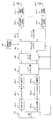
- FIG. 2 is a schematic block diagram showing the configuration of the terminal device in this embodiment.
- the terminal devices include reception antennas 201-1 to 201-R, radio reception units 202-1 to 202-R, CP removal units 203-1 to 203-R, FFT units 204-1 to 204-R, and channel estimation unit 205. , Despreading section 206, demodulation sections 207-1 to 207-U, descrambling sections 208-1 to 208-U, decoding sections 209-1 to 209-U, higher layer 210, report information generation section 211, uplink signal Generation units 212-1 to 212-T, radio transmission units 213-1 to 213-T, and transmission antennas 214-1 to 214-T are provided.
- R represents the number of receiving antennas.
- the number of transmission antennas of the terminal device is represented by the same T as that of the base station device, the number of transmission antennas of the terminal device and the base station device may be the same or different.
- an integrated circuit is formed by forming a part or all of the terminal device into a chip, it has a chip control circuit (not shown) for controlling each functional block.
- the terminal device receives signals with the receiving antennas 201-1 to 201-R, and performs frequency conversion, filtering, analog / digital conversion, etc. with the wireless receiving units 202-1 to 202-R.
- the output of radio receiving sections 202-1 to 202-R is subjected to cyclic prefix removal by CP removing sections 203-1 to 203-R, and time frequency conversion is performed by FFT sections 204-1 to 204-R.
- the channel estimation unit 205 performs channel estimation using the data demodulation reference signal and the channel measurement reference signal.
- Despreading section 206 performs despreading in the direction of the receiving antenna.
- the signals after despreading are demodulated by the demodulation units 207-1 to 207-U, respectively, and a bit LLR (Log Likelihood Ratio) is obtained.
- Descramblers 208-1 to 208-U unscramble the base station apparatus, and decoding units 209-1 to 209-U perform error correction on the outputs of descramblers 208-1 to 208-U. Decoding is performed to obtain information data, which is output to the upper layer 210.
- the terminal device also has a transmission function.
- the report information generation unit 211 generates a signal to be reported to the base station apparatus such as channel state information (CSI; Channel State Information).
- the channel state information includes a channel quality indicator (CQI; Channel Quality ⁇ Indicator), a channel estimation value, a rank indicator (RI; Rank Indicator), a precoding matrix indicator (PMI; Precoding Matrix Indicator), and the like. Further, the spreading factor and the number of multiplexed codes can be used as report information.
- Uplink signal generators 212-1 to 212-T generate uplink signals from information data, report information, and the like obtained from higher layer 210.
- the uplink signal is a signal composed of SC-FDMA (Single-Carrier--Frequency-Division-Multiple-Access) symbols and OFDMA symbols.
- SC-FDMA Single-Carrier--Frequency-Division-Multiple-Access
- the uplink signals are subjected to digital / analog conversion, filtering, frequency conversion, and the like in the radio transmission units 213-1 to 213-T, and transmitted from the transmission antennas 214-1 to 214-T.
- the base station apparatus spatially multiplexes and transmits an R sequence to one terminal apparatus.
- the base station apparatus spatially multiplexes and transmits an R sequence to one terminal apparatus.
- a case where four sequences are spatially multiplexed will be described as an example.
- the output signal s of the layer mapping unit 105 in FIG. 1 is expressed by the following equation (1).
- the superscript T represents a transposed matrix.
- s is code-multiplexed by the code multiplexer 106 as shown in the following equation (2).
- Equation (3) a case where code multiplexing is performed using an orthogonal code such as Equation (3) is shown.
- the precoding unit 108 performs precoding on the equation (2) as shown in the following equation (4).
- the base station apparatus transmits Equation (4).
- W is a precoding matrix of T rows and 4 columns. W can be obtained, for example, as a transmission maximum ratio combined weight as in the following equation (5) or a ZF weight as in the following equation (6).
- H is a 4-row T-column channel matrix having the channel between each transmitting antenna and each receiving antenna as an element. Therefore, the base station device needs to know the channel matrix. For example, in the case of TDD (Time Division Duplex), channel estimation can be performed by the base station device using channel reciprocity. Further, when channel reciprocity cannot be used even in TDD, or in the case of FDD (Frequency Division Duplex), the channel matrix can be fed back from the terminal apparatus to the base station apparatus. The channel matrix feedback may be directly fed back from the terminal device to the base station device, may be routed through another base station, may be routed through a relay station, or may be routed through another terminal device.
- TDD Time Division Duplex
- FDD Frequency Division Duplex
- the received signal in the terminal device can be expressed as in equation (7).
- Expression (7) represents a received signal in a certain subcarrier among signals output from the FFT units 204-1 to 204-R in FIG.
- n is a noise vector.
- precoding is performed using Expression (5).
- the equivalent channel matrix including the precoding matrix is expressed by the following equation (8).
- h r are the T-dimensional vector having a channel between the first r receive antenna and each transmit antenna element.
- H rt is a channel between the r-th receiving antenna and the t-th transmitting antenna.
- the diagonal element of equation (8) is the desired channel and the non-diagonal element is the interference channel.
- Equation (8) approaches the unit matrix. Therefore, if the number of transmission antennas is large, the transmission maximum ratio combined weight can easily obtain excellent transmission characteristics. Since the ZF weight also performs interference suppression, the amount of calculation is larger than that of the transmission maximum ratio combining weight, but better transmission characteristics can be obtained.
- Equation (2) This code multiplexing is code multiplexing by spreading in the direction of the receiving antenna. Therefore, if the number of streams is equal to or less than the number of reception antennas, the number of streams can be easily changed without obtaining a precoding matrix only by changing the number of multiplexed codes. For this reason, even if the difference between the number of transmitting antennas and the number of receiving antennas is small, the transmission characteristics can be improved if the number of code multiplexing is reduced.
- the despreading section 206 of the terminal apparatus despreads in the direction of the receiving antenna as shown in the following equation (11).
- despreading can be performed after detection for each receiving antenna.
- the base station apparatus performs spreading and code multiplexing in the direction of the receiving antenna and transmits, and the terminal apparatus performs despreading in the direction of the receiving antenna, thereby easily changing the number of code multiplexing. You can change the number. Therefore, since communication can be performed with a desired number of streams, transmission characteristics can be improved.
- FIG. 3 is a schematic block diagram showing the configuration of the base station apparatus in the present embodiment.
- the base station apparatus includes an upper layer 301, encoding units 302-1 to 302-U, scrambling units 303-1 to 303-U, modulation units 304-1 to 304-U, a layer mapping unit 305, a code multiplexing unit 306, Precoding unit 307, reference signal generation unit 308, resource mapping unit 309, OFDM signal generation units 310-1 to 310-T, radio transmission units 311-1 to 311-T, and transmission antennas 312-1 to 312-T are provided. .
- a chip control circuit that controls each functional block is provided.
- the difference between the present embodiment and the first embodiment is that the precoding matrix is selected from a predetermined code book, not from the channel. Since the others are the same as those in the first embodiment, the description of the same parts as those in the first embodiment is omitted.
- the upper layer 301 Based on the report information from each terminal apparatus, the upper layer 301 notifies the layer mapping unit 305 of the number of layers, notifies the code multiplexing unit 306 of the spreading factor and the number of code multiplexing, and notifies the precoding unit 308 of the PMI. .
- the layer mapping unit 305 performs layer mapping according to the number of layers.
- the code multiplexing unit 306 performs spreading and code multiplexing according to the notified spreading factor and code multiplexing number.
- the precoding unit 308 performs precoding corresponding to PMI.
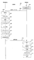
- FIG. 4 is a sequence diagram of processing between the base station apparatus and the terminal apparatus in the present embodiment.
- the base station apparatus requests the terminal apparatus to feed back CSI (step s401).
- the report information generation unit 211 generates report information to be fed back to the base station device (step s402).
- the terminal device transmits report information to the base station device (step s403).
- coding sections 302-1 to 302-U perform error correction coding (step s404), scramble sections 303-1 to 303-U scramble (step s405), and modulation sections 304-1 to 304-U. Performs modulation (step s406).
- step s407 the layer mapping unit 305 maps the modulation symbol to the layer
- step s408 the code multiplexing unit 306 performs spreading and code multiplexing in the direction of the reception antenna
- the precoding unit 308 performs precoding.
- step s410 the resource mapping unit 309 maps to resources, in step s411, the OFDM signal generation units 310-1 to 310-T generate OFDM signals, and in step s412, the OFDM signal generated in step s411 is transmitted to the terminal device. Send to.
- the FFT units 204-1 to 204-R perform FFT on the received signal (step s413), the despreading unit 206 despreads toward the receiving antenna (step s414), and the demodulation units 207-1 to 207-U. Is demodulated (step s415), the descrambling units 208-1 to 208-U are descrambled (step s416), and the decoding units 209-1 to 209-U perform error correction decoding (step s417).
- the precoding matrix is selected from the code book. For this reason, the terminal device does not need to feed back the channel matrix, and can reduce the amount of feedback information. Further, it is preferable to obtain a precoding matrix to be fed back for each receiving antenna to be spread.
- FIG. 5 is a schematic block diagram showing the configuration of the base station apparatus in the present embodiment.
- the base station apparatus includes an upper layer 501, encoding units 502-1 to 502-U, scrambling units 503-1 to 503-U, modulation units 504-1 to 504-U, a layer mapping unit 505, a code multiplexing unit 506, Precoding units 507-1 and 507-2, reference signal generation unit 508, resource mapping unit 509, OFDM signal generation units 510-1-1 to 510-1-T, 510-2-1 to 510-2-T, Wireless transmission units 511-1-1 to 511-1-T, 511-2-1 to 511-2-T, transmission antennas 512-1-1 to 5121-2-T, 512-2-1 to 512-2 -T.
- the transmission antennas 512-1-1 to 512-1-T and the transmission antennas 512-2-1 to 512-2-T transmit with different polarizations.
- Polarization includes vertical polarization, horizontal polarization, circular polarization, and the like.
- the present invention is not limited to this.
- the number of different polarization antennas is the same T, but the number may be different.
- the precoding units 507-1 and 507-2 are different polarization precodings.
- precoding for example, equations (5) and (6) can be used, and a code book can also be used.
- a different precoding method can be used for each polarization. For example, a weight such as Equations (5) and (6) can be used for a certain polarization, and a code book can be used for another polarization. Also, equation (5) can be used for a certain polarization, and equation (6) can be used for another polarization.
- FIG. 6 is a schematic block diagram showing the configuration of the terminal device in this embodiment.
- the terminal devices include reception antennas 601-1-1 to 601-1-R, 601-2-1 to 601-2-R, and wireless reception units 602-1-1 to 602-1-R, 602-2-1. 602-2-R, CP removal units 603-1-1 to 603-1-R, 603-2-1, 603-2-R, FFT units 604-1-1 to 604-1-R, 604 2-1 to 604-2-R, channel estimation unit 605, despreading unit 606, demodulation units 607-1 to 607-U, descrambling units 608-1 to 608-U, decoding units 609-1 to 609-U
- the upper layer 610 is provided.
- the receiving antennas 601-1-1 to 601-1-R and the receiving antennas 601-2-1 to 601-2-R are different polarization antennas.
- the number of antennas is R for both polarizations, they may be different.
- the terminal devices receive signals with the receiving antennas 601-1-1 to 601-1-R and 601-2-1 to 601-2-R, and wireless receiving units 602-1-1 to 602-1-R, 602-2-1 to 602-2 -R perform frequency conversion, filtering, analog / digital conversion, and the like.
- the outputs of the radio receiving units 602-1-1 to 602-1-R and 602-2-1 to 602-2-R are output from the CP removing units 603-1-1 to 603-1-R, 603-2-1.
- the cyclic prefix is removed by ⁇ 603-2-R, and the time-frequency conversion is performed by the FFT units 604-1-1 to 604-1 -R and 604-2-1 to 604-2 -R.
- the channel estimation unit 605 performs channel estimation using the reference signal.
- the despreading unit 606 performs despreading. Despreading is performed in the direction of the receiving antenna. Subsequent processing is the same as that in the first and second embodiments, and thus description thereof is omitted.
- communication is performed using a plurality of polarization antennas. For this reason, since interference can be reduced, transmission characteristics can be improved.
- the case of spreading only in the direction of the receiving antenna of the terminal device has been described, but it is also possible to spread in the time direction and the frequency direction in addition to the spatial direction. Transmission characteristics can be improved by spreading in the time direction and frequency direction so as to suppress inter-stream interference.
- code multiplexing is performed by spreading in the direction of the receiving antenna of the terminal device.
- code multiplexing is performed after performing interleaving for rearranging the spread signals.
- the terminal apparatus performs de-spreading after de-interleaving, which is de-interleaving processing after detection.
- signals are multiplexed after interleaving, the same spreading code and different interleaving patterns may be used for each multiplexed signal.
- the interleaving described here can be performed not only in the direction of the receiving antenna of the terminal apparatus but also in the time direction and / or the frequency direction.
- the case where a spreading code is used for the spreading process has been described as an example, but the case where the spreading process is performed by channel coding is also included in the present embodiment.
- this embodiment also includes a case where spreading processing is performed by channel coding with coding rate R instead of using spreading code with spreading factor R.
- different interleaving can be applied to each of the multiplexed signals.
- the terminal device may perform channel decoding after deinterleaving after detection.
- the terminal device can use information of another signal that has already been detected in the despreading process for a certain signal, and can repeatedly perform the process.
- the program that operates in the base station apparatus and mobile station apparatus is a program (a program that causes a computer to function) that controls the CPU and the like so as to realize the functions of the above-described embodiments according to the present invention.
- Information handled by these devices is temporarily stored in the RAM at the time of processing, then stored in various ROMs and HDDs, read out by the CPU, and corrected and written as necessary.
- a recording medium for storing the program a semiconductor medium (for example, ROM, nonvolatile memory card, etc.), an optical recording medium (for example, DVD, MO, MD, CD, BD, etc.), a magnetic recording medium (for example, magnetic tape, Any of a flexible disk etc. may be sufficient.
- the processing is performed in cooperation with the operating system or other application programs.
- the functions of the invention may be realized.
- the program when distributing to the market, can be stored and distributed on a portable recording medium, or transferred to a server computer connected via a network such as the Internet.
- the storage device of the server computer is also included in the present invention.
- Each functional block of the receiving apparatus may be individually formed as a chip, or a part or all of them may be integrated into a chip. When each functional block is integrated, an integrated circuit controller for controlling them is added.
- the method of circuit integration is not limited to LSI, and may be realized by a dedicated circuit or a general-purpose processor.
- an integrated circuit based on the technology can also be used.
- the terminal device of the present invention is not limited to application to a mobile station device, but is a stationary or non-movable electronic device installed indoors or outdoors, such as AV equipment, kitchen equipment, cleaning / washing equipment Needless to say, the present invention can be applied to air conditioning equipment, office equipment, vending machines, and other daily life equipment.
- the present invention is suitable for use in a base station device, a terminal device, a transmission method, and a reception method.
Landscapes
- Engineering & Computer Science (AREA)
- Signal Processing (AREA)
- Computer Networks & Wireless Communication (AREA)
- Radio Transmission System (AREA)
Abstract
送信アンテナ数と受信アンテナ数の差が小さい場合であっても、良好な伝送特性を得る。変調シンボルを端末装置の受信アンテナの方向に拡散及びコード多重し、プリコーディングして送信する。そして、受信アンテナの方向に拡散を行なう拡散コードの拡散率は、端末装置の受信アンテナ数であることを特徴とする。受信アンテナ方向に拡散コード多重することにより、多重数を変えることで、送信アンテナ数と受信アンテナ数の差が小さい場合であっても、良好な伝送特性が得られる基地局装置及び端末装置を提供することができる。
Description
本発明は、基地局装置、端末装置、送信方法及び受信方法に関する。
複数の送信アンテナ及び受信アンテナを用いて伝送を行なうMIMO(Multiple Input Multiple Output)伝送は、周波数帯域幅を広げずに伝送レートを向上させることができるため、LTE(Long Term Evolution)や無線LAN(Local Area Network)等で採用されている。
近年、アンテナ数を大幅に増やしたMIMO伝送が注目されている。このようなMIMO伝送はMassive MIMO、Large Scale MIMO、Full Dimension MIMOなどと呼ばれている。受信アンテナ数と比較して送信アンテナ数が非常に多くした場合では、MIMOのチャネル行列をHとしたとき、プリコーディング行列としてHHを用いるだけで、所望信号に対するゲインと干渉信号に対するゲインには大きな差が生じるため、非常に容易に干渉抑圧が可能となる。このようなMassive MIMOについては、非特許文献1に記載されている。
F.Rusek、D.Persson、K.Lau、E.G.Larsson、T.L.Marzetta、O.Edfors、and F.Tufvesson、"Scaling up MIMO:Opportunities and Challenges with Very Large Arrays、" IEEE Signal Processing Magazine、2013年 1月。
しかしながら、非特許文献1に記載されている技術は、送信アンテナ数が受信アンテナ数と比較して非常に多い場合にのみ効果が生じ、受信アンテナ数が多くなってくると、所望信号と干渉信号のゲインの差が小さくなるため、伝送特性が劣化してしまうという問題がある。
本発明は、このような事情を鑑みてなされてものであり、その目的は、送信アンテナ数と受信アンテナ数の差が小さい場合であっても、良好な伝送特性が得られる基地局装置、端末装置、送信方法及び受信方法を提供することにある。
上述した課題を解決するために本発明に係る基地局装置、端末装置の構成は、次の通りである。
本発明の基地局装置は、変調シンボルを端末装置の受信アンテナの方向に拡散及びコード多重し、プリコーディングして送信することを特徴とする。
また、本発明の基地局装置において、前記受信アンテナの方向に拡散を行なう拡散コードの拡散率は、端末装置の受信アンテナ数であることを特徴とする。
また、本発明の基地局装置において、端末装置からフィードバックされるコード多重数を示す情報に基づいて、コード多重数を決めることを特徴とする。
また、本発明の基地局装置において、前記プリコーディングの重み行列は予め設定されたコードブックから選択されることを特徴とする。
また、本発明の基地局装置において、複数の偏波アンテナを用いて送信することを特徴とする。
また、本発明の基地局装置において、前記受信アンテナ方向に加え、時間方向に拡散することを特徴とする。
また、本発明の基地局装置において、前記受信アンテナ方向に加え、周波数方向に拡散することを特徴とする
また、本発明の端末装置は、各受信アンテナで受信した受信信号を受信アンテナ方向に逆拡散する逆拡散部を備えることを特徴とする。
また、本発明の端末装置において、コード多重数を示す情報を基地局装置にフィードバックすることを特徴とする。
また、本発明の端末装置において、受信アンテナごとにプリコーディング行列をコードブックから選択し、前記プリコーディング行列を示す情報を基地局装置にフィードバックすることを特徴とする。
また、本発明の端末装置において、複数の偏波アンテナを備え、前記偏波アンテナの方向に逆拡散することを特徴とする。
また、本発明の送信方法は、変調シンボルを端末装置の受信アンテナの方向に拡散及びコード多重し、プリコーディングして送信することを特徴とする。
また、本発明の受信方法は、各受信アンテナで受信した受信信号を受信アンテナ方向に逆拡散する逆拡散ステップを備えることを特徴とする。
本発明では、受信アンテナ方向に拡散コード多重するようにした。このため、多重数を変えることで、送信アンテナ数と受信アンテナ数の差が小さい場合であっても、良好な伝送特性を得ることができる。
以下、本発明の実施形態について説明する。実施形態における通信システムは、基地局装置(送信装置、セル、送信点、送信アンテナ群、送信アンテナポート群、コンポーネントキャリア、eNodeB)および端末装置(移動端末、受信点、受信端末、受信装置、受信アンテナ群、受信アンテナポート群、User Equipment)を備える。なお、以下の実施形態では、下りリンクについて説明するが、本発明はこれに限らず、上りリンクでも適用可能である。また、以下の実施形態では、OFDM(直交周波数分割多重:Orthogonal Frequency Dvision Multiplexing)に本発明を適用した例を説明するが、本発明はこれに限らず、シングルキャリア伝送などその他の方式にも適用可能である。
(第1の実施形態)
図1は本実施形態における基地局装置の構成を示す概略ブロック図である。基地局装置は、上位レイヤ101、符号化部102-1~102-U、スクランブル部103-1~103-U、変調部104-1~104-U、レイヤマッピング部105、コード多重部106、プリコーディング部107、参照信号生成部108、リソースマッピング部109、OFDM信号生成部110-1~110-T、無線送信部111-1~111-T、送信アンテナ112-1~112-Tを備える。なお、図中のUはコードワード数を表す。また、Tは送信アンテナ数を表す。なお、上記基地局装置の一部あるいは全部をチップ化して集積回路となる場合、各機能ブロックに対して制御を行なうチップ制御回路を有する。
図1は本実施形態における基地局装置の構成を示す概略ブロック図である。基地局装置は、上位レイヤ101、符号化部102-1~102-U、スクランブル部103-1~103-U、変調部104-1~104-U、レイヤマッピング部105、コード多重部106、プリコーディング部107、参照信号生成部108、リソースマッピング部109、OFDM信号生成部110-1~110-T、無線送信部111-1~111-T、送信アンテナ112-1~112-Tを備える。なお、図中のUはコードワード数を表す。また、Tは送信アンテナ数を表す。なお、上記基地局装置の一部あるいは全部をチップ化して集積回路となる場合、各機能ブロックに対して制御を行なうチップ制御回路を有する。
上位レイヤ101は、OSI参照モデルで定義された通信機能の階層のうち、物理層(Physical Layer)よりも上位の機能の階層、例えばMAC(媒体アクセス制御:Media Access Control)層、データリンク層、ネットワーク層等である。また、上位レイヤ101は、基地局装置を構成する各部位が、機能を発揮するために必要なその他のパラメータも通知する。
符号化部102-1~102-Uは、上位レイヤ101から入力された情報データに対して、誤り訂正符号化を行ない、符号化ビット(コードワードともいう)を生成する。また、情報データは、例えば、通話に伴う音声信号、撮影した画像を表す静止画像又は動画像信号、文字メッセージ等である。符号化部102-1~102-Uが誤り訂正符号化を行なう際に用いる符号化方式は、例えば、ターボ符号化(Turbo Coding)、畳み込み符号化(Convolutional Coding)、低密度パリティ検査符号化(Low Density Parity Check coding;LDPC)等である。
なお、符号化部102-1~102-Uは、誤り訂正符号化したデータ系列の符号化率(coding rate)をデータ伝送率に対応する符号化率に合わせるために、符号化ビット系列に対してレートマッチング処理を行なってもよい。また、符号化部102-1~102-Uは、誤り訂正符号化したデータ系列を並び替えてインターリーブする機能を有してもよい。
スクランブル部103-1~103-Uは、各コードワードに対して、それぞれセルIDに基づいたスクランブルを行なう。
スクランブルされたコードワードは、変調部104-1~104-Uにおいて、変調シンボルにマッピングされる。変調部104-1~104-Uが行なう変調処理は、例えば、BPSK(Binary Phase Shift Keying;2相位相変調)、QPSK(Quadrature Phase Shift Keying;4相位相変調)、M-QAM(M-Quadrature Amplitude Modulation;M値直交振幅変調、例えば、M=16、64、256、1024、4096)などである。なお、変調部104-1~104-Uは、生成した変調シンボルを並び替えてインターリーブする機能を有してもよい。
変調シンボルは、レイヤマッピング部105において、空間多重のためにレイヤマッピングされる。なお、レイヤ数はSで表す。
コード多重部106は、レイヤマッピングされた信号を、拡散コードを用いて、端末装置の受信アンテナ方向(レイヤ方向、空間方向)に拡散コード多重する。拡散コードは、アダマール符号、DFT(離散フーリエ変換;Discrete Fourier Transform)系列、Gold符号等、直交符号、準直交符号に関わらず用いることができる。拡散率は端末装置の受信アンテナ数に基づいて決まり、ある端末装置への最大の拡散率は受信アンテナ数となる。また、端末装置毎に拡散率を変えることも可能である。また、時空間ブロック符号化に基づいて拡散多重を行なっても構わない。この場合、時空間ブロック符号の符号長が本実施形態における拡散率に相当する。なお、従来の時空間ブロック符号化は時間(又は周波数)と送信アンテナにおける符号化であるが、本発明を適用した場合は、時間(又は周波数)と受信アンテナにおける符号化となる。
参照信号生成部107は、参照信号を生成し、プリコーディングを行なう参照信号をプリコーディング部108に、プリコーディングしない参照信号をリソースマッピング部109-1~109-Tに出力する。
プリコーディング部108は、ビームを形成するプリコーディングを行なう。例えば、送信最大比合成重み、ZF(Zero Forcing)重みを用いることができる。なお、参照信号生成部107から入力される参照信号についてもプリコーディングを行なう。
リソースマッピング部109は、プリコーディング部109の出力、参照信号をリソースにマッピングする。ここで、リソースとは、所定の周波数帯域や時間区間から構成される領域である。
リソースマッピング部109の出力は、OFDM信号生成部110-1~110-TでIFFT(逆高速フーリエ変換:Inverse Fast Fourier Transform)、サイクリックプレフィックス(CP:Cyclic Prefix)の挿入が行なわれ、送信部111-1~111-Tでデジタル・アナログ変換、フィルタリング、周波数変換等が行なわれ、送信アンテナ112-1~112-Tから送信される。
図2は本実施形態における端末装置の構成を示す概略ブロック図である。端末装置は、受信アンテナ201-1~201-R、無線受信部202-1~202-R、CP除去部203-1~203-R、FFT部204-1~204-R、チャネル推定部205、逆拡散部206、復調部207-1~207-U、デスクランブル部208-1~208-U、復号部209-1~209-U、上位レイヤ210、報告情報生成部211、上りリンク信号生成部212-1~212-T、無線送信部213-1~213-T、送信アンテナ214-1~214-Tを備える。なお、図中のRは受信アンテナ数を表す。また、端末装置の送信アンテナ数を基地局装置と同じTで表しているが、端末装置と基地局装置の送信アンテナ数は同じであっても異なっていてもよい。また、端末装置の一部あるいは全部をチップ化して集積回路となる場合、各機能ブロックに対して制御を行なうチップ制御回路(図示せず)を有する。
端末装置は、受信アンテナ201-1~201-Rで信号を受信し、無線受信部202-1~202-Rで周波数変換、フィルタリング、アナログ・デジタル変換等を行なう。無線受信部202-1~202-Rの出力は、CP除去部203-1~203-Rでサイクリックプレフィックスの除去が行なわれ、FFT部204-1~204-Rで時間周波数変換が行なわれる。チャネル推定部205は、データ復調用参照信号やチャネル測定用参照信号を用いてチャネル推定を行なう。逆拡散部206は、受信アンテナ方向に逆拡散を行なう。逆拡散後の信号は、それぞれ、復調部207-1~207-Uで復調が行なわれ、ビットLLR(対数尤度比;Log Likelihood Ratio)が求められる。デスクランブル部208-1~208-Uは、基地局装置で行なわれたスクランブルを解き、復号部209-1~209-Uはデスクランブル部208-1~208-Uの出力に対して誤り訂正復号を行ない、情報データを求め、上位レイヤ210に出力する。
端末装置は送信する機能も備える。報告情報生成部211は、チャネル状態情報(CSI;Channel State Information)等の基地局装置に報告する信号を生成する。チャネル状態情報には、チャネル品質指標(CQI;Channel Quality Indicator)、チャネル推定値、ランク指標(RI;Rank Indicator)、プリコーディング行列指標(PMI;Precoding Matrix Indicator)等を含む。また、拡散率、コード多重数を報告情報とすることもできる。上りリンク信号生成部212-1~212-Tは、上位レイヤ210から得られる情報データや報告情報等から上りリンク信号を生成する。上りリンク信号はSC-FDMA(Single Carrier - Frequency Division Multiple Access)シンボルやOFDMAシンボルで構成された信号である。上りリンク信号は、無線送信部213-1~213-Tでデジタル・アナログ変換、フィルタリング、周波数変換等が行なわれ、送信アンテナ214-1~214-Tから送信される。
基地局装置、端末装置の動作の詳細を、数式を用いて説明する。本実施形態では、基地局装置は1つの端末装置に対して、最大でR系列を空間多重して送信する。ここでは、4系列を空間多重する場合を例に説明する。このとき、図1のレイヤマッピング部105の出力信号sを次式(1)のように表す。

ただし、上付きのTは転置行列を表す。sは、コード多重部106で、次式(2)のようにコード多重される。なお、一例として、式(3)のような直交符号を用いてコード多重する場合を示す。

プリコーディング部108は、式(2)に対して次式(4)のようにプリコーディングを行なう。基地局装置は式(4)を送信する。

なお、WはT行4列のプリコーディング行列である。Wは、例えば、次式(5)のような送信最大比合成重みや、次式(6)のようなZF重みとして求めることができる。

ただし、Hは各送信アンテナと各受信アンテナとの間のチャネルを要素に持つ4行T列のチャネル行列である。従って、基地局装置でチャネル行列を知る必要があるが、例えば、TDD(時分割複信;Time Division Duplex)の場合、チャネルの相反性を利用して基地局装置でチャネル推定することができる。また、TDDでもチャネルの相反性が利用できない場合や、FDD(周波数分割複信;Frequency Dvision Duplex)の場合、端末装置から基地局装置にチャネル行列をフィードバックすることができる。なお、チャネル行列のフィードバックは、端末装置から基地局装置に直接フィードバックしてもよいし、他の基地局経由でもよいし、中継局経由でもよいし、他の端末装置経由でもよい。
端末装置における受信信号は式(7)のように表せる。ただし、式(7)は、図2のFFT部204-1~204-Rが出力する信号のうちの、あるサブキャリアにおける受信信号を表している。

ただし、nは雑音ベクトルである。ここで、式(5)でプリコーディングしたとする。このとき、プリコーディング行列を含む等価チャネル行列は、次式(8)のようになる。
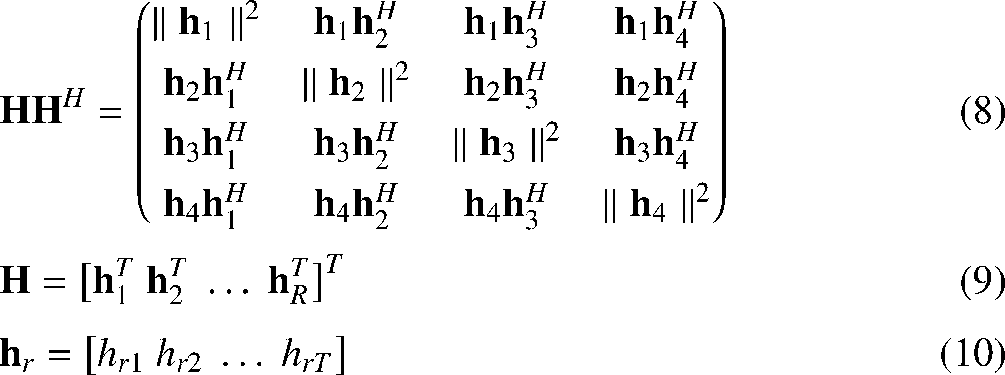
ただし、hrは第r受信アンテナと各送信アンテナとの間のチャネルを要素に持つT次元ベクトルである。またhrtは第r受信アンテナと第t送信アンテナとの間のチャネルである。式(8)の対角要素が所望チャネルで非対角要素が干渉チャネルである。TがRよりも大きくなるにつれて、式(8)は単位行列に近づいていくため、送信アンテナ数が多ければ、送信最大比合成重みは、容易に優れた伝送特性が得られる。ZF重みは干渉抑圧も行なうため、送信最大比合成重みと比べて演算量は多くなるが、よりよい伝送特性が得られる。
なお、式(8)の等価チャネルは、1つのストリームを1つの受信アンテナに向けて送信していることになり、ストリーム数を変える場合は受信アンテナ数を変える必要がある。従って、式(5)や式(6)のようなプリコーディングでは、ストリーム数を変更する際に、チャネルが変動していなかったとしても、改めて重みを求めなければならないため、ストリーム数の変更を容易に行なうことはできない。そこで、本実施形態では、式(2)のようにコード多重している。このコード多重は受信アンテナの方向に拡散してコード多重していることになる。従って、受信アンテナ数以下のストリーム数であれば、コード多重数を変えるだけで、プリコーディング行列を求めなくても、ストリーム数を容易に変更することができる。このため、送信アンテナ数と受信アンテナ数の差が小さくても、コード多重数を少なくすれば、伝送特性を向上させることができる。
基地局装置で受信アンテナ方向にコード多重されて送信されているため、端末装置の逆拡散部206は、次式(11)のように受信アンテナの方向に逆拡散する。

なお、受信アンテナ毎に検波した後で逆拡散することもできる。
このように本実施形態では、基地局装置で、受信アンテナ方向に拡散及びコード多重して送信し、端末装置で受信アンテナ方向に逆拡散することで、コード多重数を変えるだけで、容易にストリーム数を変えることができるようになる。従って、所望のストリーム数で通信することができるため、伝送特性を向上させることができる。
(第2の実施形態)
(第2の実施形態)
図3は本実施形態における基地局装置の構成を示す概略ブロック図である。基地局装置は、上位レイヤ301、符号化部302-1~302-U、スクランブル部303-1~303-U、変調部304-1~304-U、レイヤマッピング部305、コード多重部306、プリコーディング部307、参照信号生成部308、リソースマッピング部309、OFDM信号生成部310-1~310-T、無線送信部311-1~311-T、送信アンテナ312-1~312-Tを備える。なお、上記基地局装置の一部あるいは全部をチップ化して集積回路となる場合、各機能ブロックに対して制御を行なうチップ制御回路を有する。本実施形態と第1の実施形態との違いは、プリコーディング行列を、チャネルから求めるのではなく、予め決められたコードブックから選択することである。その他は第1の実施形態と同様であるので、第1の実施形態と同様の部分の説明は割愛する。
上位レイヤ301は、各端末装置からの報告情報に基づき、レイヤ数をレイヤマッピング部305に通知し、拡散率及びコード多重数をコード多重部306に通知し、PMIをプリコーディング部308に通知する。レイヤマッピング部305は、レイヤ数に従ってレイヤマッピングを行なう。コード多重部306は通知された拡散率及びコード多重数に従って拡散及びコード多重を行なう。プリコーディング部308は、PMIに対応するプリコーディングを行なう。
図4は本実施形態における基地局装置と端末装置との間の処理のシーケンス図である。基地局装置は、端末装置に対してCSIをフィードバックすることを要求する(ステップs401)。端末装置では、基地局装置にフィードバックする報告情報を報告情報生成部211が生成する(ステップs402)。端末装置は報告情報を基地局装置に送信する(ステップs403)。
基地局装置では、符号化部302-1~302-Uが誤り訂正符号化(ステップs404)、スクランブル部303-1~303-Uがスクランブル(ステップs405)、変調部304-1~304-Uが変調を行なう(ステップs406)。ステップs407では、レイヤマッピング部305が変調シンボルをレイヤにマッピングし、ステップs408では、コード多重部306が受信アンテナ方向に拡散及びコード多重を行ない、ステップs409では、プリコーディング部308がプリコーディングし、ステップs410では、リソースマッピング部309がリソースにマッピングし、ステップs411では、OFDM信号生成部310-1~310-TがOFDM信号を生成し、ステップs412では、ステップs411で生成したOFDM信号を端末装置に送信する。
端末装置では、FFT部204-1~204-Rが受信信号をFFTし(ステップs413)、逆拡散部206が受信アンテナ方向に逆拡散し(ステップs414)、復調部207-1~207-Uが復調し(ステップs415)、デスクランブル部208-1~208-Uがデスクランブルし(ステップs416)、復号部209-1~209-Uが誤り訂正復号する(ステップs417)。
このように本実施形態では、コードブックからプリコーディング行列を選択するようにした。このため、端末装置は、チャネル行列をフィードバックする必要はなく、フィードバック情報量を削減することができる。また、フィードバックするプリコーディング行列は、拡散する受信アンテナ毎に求めることが好適である。
(第3の実施形態)
(第3の実施形態)
図5は本実施形態における基地局装置の構成を示す概略ブロック図である。基地局装置は、上位レイヤ501、符号化部502-1~502-U、スクランブル部503-1~503-U、変調部504-1~504-U、レイヤマッピング部505、コード多重部506、プリコーディング部507-1、507-2、参照信号生成部508、リソースマッピング部509、OFDM信号生成部510-1-1~510-1-T、510-2-1~510-2-T、無線送信部511-1-1~511-1-T、511-2-1~511-2-T、送信アンテナ512-1-1~512-1-T、512-2-1~512-2-T、を備える。
本実施形態では、送信アンテナ512-1-1~512-1-Tと送信アンテナ512-2-1~512-2-Tは異なる偏波で送信する。偏波には、垂直偏波、水平偏波、円偏波等がある。本実施形態では、2つの偏波を用いて送信する例を説明するが、本発明はこれに限らない。また、異なる偏波アンテナの本数を同じTとしているが、本数は異なってもよい。
プリコーディング部507-1、507-2以外のブロックは、上記第1、2の実施形態と同様であるので、ここではプリコーディング部507-1、507-2のみ説明する。プリコーディング部507-1、507-2は、それぞれ異なる偏波用のプリコーディングである。プリコーディングは、例えば、式(5)や(6)を用いることができるし、コードブックを用いることもできる。なお、偏波ごとに異なるプリコーディング方式を用いることもできる。例えば、ある偏波では式(5)、(6)のような重みを用い、別の偏波ではコードブックを用いることができる。また、ある偏波では式(5)を用い、別の偏波では式(6)を用いることもできる。
図6は本実施形態における端末装置の構成を示す概略ブロック図である。端末装置は、受信アンテナ601-1-1~601-1-R、601-2-1~601-2-R、無線受信部602-1-1~602-1-R、602-2-1~602-2-R、CP除去部603-1-1~603-1-R、603-2-1、603-2-R、FFT部604-1-1~604-1-R、604-2-1~604-2-R、チャネル推定部605、逆拡散部606、復調部607-1~607-U、デスクランブル部608-1~608-U、復号部609-1~609-U、上位レイヤ610を備える。
ここでは、受信アンテナ601-1-1~601-1-Rと受信アンテナ601-2-1~601-2-Rは異なる偏波アンテナとする。なお、どちらの偏波もアンテナ本数をRとしているが、異なってもよい。
端末装置は、受信アンテナ601-1-1~601-1-R、601-2-1~601-2-Rで信号を受信し、無線受信部602-1-1~602-1-R、602-2-1~602-2-Rで、周波数変換、フィルタリング、アナログ・デジタル変換等を行なう。無線受信部602-1-1~602-1-R、602-2-1~602-2-Rの出力は、CP除去部603-1-1~603-1-R、603-2-1~603-2-Rでサイクリックプレフィックスを除去され、FFT部604-1-1~604-1-R、604-2-1~604-2-Rで時間周波数変換が行なわれる。チャネル推定部605は、参照信号を用いてチャネル推定を行なう。逆拡散部606は、逆拡散を行なう。逆拡散は、受信アンテナの方向に行なわれる。以降の処理は、第1、2の実施形態と同様であるので、説明は省略する。
このように本実施形態では、複数の偏波アンテナを用いて通信するようにした。このため、干渉を軽減することができるため、伝送特性を向上させることができる。
なお、本実施形態では、異なる偏波アンテナにも拡散したが、同じ偏波アンテナ内で拡散してもよい。
以上、上記第1から第3の実施形態では、端末装置の受信アンテナ方向のみに拡散する場合を説明したが、空間方向に加えて、時間方向や周波数方向に拡散することも可能である。ストリーム間干渉を抑圧するように時間方向や周波数方向に拡散することによって、伝送特性を向上させることができる。
また、上記第1から第3の実施形態では、端末装置の受信アンテナ方向に拡散してコード多重する場合を説明したが、拡散した信号の並び替えを行なうインターリーブを行なった後、コード多重することも可能である。この場合、端末装置は、検波後にインターリーブの逆処理であるデインターリーブを行なった後、逆拡散処理を行なう。なお、インターリーブ後に信号を多重する場合、多重する信号の各々で同じ拡散コード、異なるインターリーブパターンを用いればよい。なお、ここで説明したインターリーブは、端末装置の受信アンテナ方向のみならず、時間方向及び/又は周波数方向にも行なうことができる。
また、上記第1から第3の実施形態では、拡散処理に拡散符号を用いる場合を例にとって説明を行なってきたが、拡散処理はチャネル符号化によって行なわれる場合も本実施形態には含まれる。例えば、拡散率Rの拡散符号が用いられる代わりに、符号化率Rのチャネル符号化によって拡散処理が行なわれる場合も本実施形態には含まれる。この場合も、多重する信号の各々には、異なるインターリーブが適用されることが可能である。端末装置は、検波後にデインターリーブを行なった後、チャネル復号を行なえばよい。また、端末装置は、ある信号に対する逆拡散処理の際に、すでに検出済みの他の信号の情報を用いることも可能であり、当該処理を繰り返し行なうことも可能である。
なお、本発明に係る基地局装置及び移動局装置で動作するプログラムは、本発明に関わる上記実施形態の機能を実現するように、CPU等を制御するプログラム(コンピュータを機能させるプログラム)である。そして、これら装置で取り扱われる情報は、その処理時に一時的にRAMに蓄積され、その後、各種ROMやHDDに格納され、必要に応じてCPUによって読み出し、修正・書き込みが行なわれる。プログラムを格納する記録媒体としては、半導体媒体(例えば、ROM、不揮発性メモリカード等)、光記録媒体(例えば、DVD、MO、MD、CD、BD等)、磁気記録媒体(例えば、磁気テープ、フレキシブルディスク等)等のいずれであってもよい。また、ロードしたプログラムを実行することにより、上述した実施形態の機能が実現されるだけでなく、そのプログラムの指示に基づき、オペレーティングシステムあるいは他のアプリケーションプログラム等と共同して処理することにより、本発明の機能が実現される場合もある。
また市場に流通させる場合には、可搬型の記録媒体にプログラムを格納して流通させたり、インターネット等のネットワークを介して接続されたサーバコンピュータに転送したりすることができる。この場合、サーバコンピュータの記憶装置も本発明に含まれる。また、上述した実施形態における移動局装置および基地局装置の一部、または全部を典型的には集積回路であるLSIとして実現してもよい。受信装置の各機能ブロックは個別にチップ化してもよいし、一部、または全部を集積してチップ化してもよい。各機能ブロックを集積回路化した場合に、それらを制御する集積回路制御部が付加される。
また、集積回路化の手法はLSIに限らず専用回路、または汎用プロセッサで実現してもよい。また、半導体技術の進歩によりLSIに代替する集積回路化の技術が出現した場合、当該技術による集積回路を用いることも可能である。
なお、本願発明は上述の実施形態に限定されるものではない。本願発明の端末装置は、移動局装置への適用に限定されるものではなく、屋内外に設置される据え置き型、または非可動型の電子機器、たとえば、AV機器、キッチン機器、掃除・洗濯機器、空調機器、オフィス機器、自動販売機、その他生活機器などに適用できることはいうまでもない。
以上、この発明の実施形態を、図面を参照して詳述してきたが、具体的な構成はこの実施形態に限られるものではなく、この発明の要旨を逸脱しない範囲の設計等も特許請求の範囲に含まれる。
本発明は、基地局装置、端末装置、送信方法及び受信方法に用いて好適である。
なお、本国際出願は、2013年12月13日に出願した日本国特許出願第2013-257537号に基づく優先権を主張するものであり、日本国特許出願第2013-257537号の全内容を本国際出願に援用する。
101、210、301、501、610 上位レイヤ
102-1~102-U、302-1~302-U、502-1~502-U 符号化部
103-1~103-U、303-1~303-U、503-1~503-U スクランブル部
104-1~104-U、304-1~304-U、504-1~504-U 変調部
105、305、505 レイヤマッピング部
106、306、506 コード多重部
107、307、508 参照信号生成部
108、308、507-1、507-2 プリコーディング部
109、309、509 リソースマッピング部
110-1~110-T、310-1~310-T、510-1-1~510-1-T、510-2-1~510-2-T OFDM信号生成部
111-1~111-T、213-1~213-T、311-1~311-T、511-1-1~511-1-T、511-2-1~511-2-T 無線送信部
112-1~112-T、214-1~214-T、312-1~312-T、512-1-1~512-1-T、512-2-1~512-2-T 送信アンテナ
201-1~201-R、601-1-1~601-1-R 受信アンテナ
202-1~202-R、602-1-1~602-1-R 無線受信部
203-1~203-R、603-1-1~603-1-R CP除去部
204-1~204-R、604-1-1~604-1-R FFT部
205、605 チャネル推定部
206、606 逆拡散部
207-1~207-U、607-1~607-U 復調部
208-1~208-U、608-1~608-U デスクランブル部
209-1~209-U、609-1~609-U 復号部
211 報告情報生成部
212-1~212-T 上りリンク信号生成部
102-1~102-U、302-1~302-U、502-1~502-U 符号化部
103-1~103-U、303-1~303-U、503-1~503-U スクランブル部
104-1~104-U、304-1~304-U、504-1~504-U 変調部
105、305、505 レイヤマッピング部
106、306、506 コード多重部
107、307、508 参照信号生成部
108、308、507-1、507-2 プリコーディング部
109、309、509 リソースマッピング部
110-1~110-T、310-1~310-T、510-1-1~510-1-T、510-2-1~510-2-T OFDM信号生成部
111-1~111-T、213-1~213-T、311-1~311-T、511-1-1~511-1-T、511-2-1~511-2-T 無線送信部
112-1~112-T、214-1~214-T、312-1~312-T、512-1-1~512-1-T、512-2-1~512-2-T 送信アンテナ
201-1~201-R、601-1-1~601-1-R 受信アンテナ
202-1~202-R、602-1-1~602-1-R 無線受信部
203-1~203-R、603-1-1~603-1-R CP除去部
204-1~204-R、604-1-1~604-1-R FFT部
205、605 チャネル推定部
206、606 逆拡散部
207-1~207-U、607-1~607-U 復調部
208-1~208-U、608-1~608-U デスクランブル部
209-1~209-U、609-1~609-U 復号部
211 報告情報生成部
212-1~212-T 上りリンク信号生成部
Claims (13)
- 変調シンボルを端末装置の受信アンテナの方向に拡散及びコード多重し、プリコーディングして送信することを特徴とする基地局装置。
- 前記受信アンテナの方向に拡散を行なう拡散コードの拡散率は、端末装置の受信アンテナ数であることを特徴とする請求項1に記載の基地局装置。
- 端末装置からフィードバックされるコード多重数を示す情報に基づいて、コード多重数を決めることを特徴とする請求項1または2のいずれかの項に記載の基地局装置。
- 前記プリコーディングの重み行列は予め設定されたコードブックから選択されることを特徴とする請求項1から3のいずれかに記載の基地局装置。
- 複数の偏波アンテナを用いて送信することを特徴とする請求項1から4のいずれかに記載の基地局装置。
- 前記受信アンテナ方向に加え、時間方向に拡散することを特徴とする請求項1から5のいずれかに記載の基地局装置。
- 前記受信アンテナ方向に加え、周波数方向に拡散することを特徴とする請求項1から5のいずれかに記載の基地局装置。
- 各受信アンテナで受信した受信信号を受信アンテナ方向に逆拡散する逆拡散部を備えることを特徴とする端末装置。
- コード多重数を示す情報を基地局装置にフィードバックすることを特徴とする請求項8に記載の端末装置。
- 受信アンテナごとにプリコーディング行列をコードブックから選択し、前記プリコーディング行列を示す情報を基地局装置にフィードバックすることを特徴とする請求項9に記載の端末装置。
- 複数の偏波アンテナを備え、前記偏波アンテナの方向に逆拡散することを特徴とする請求項10に記載の端末装置。
- 変調シンボルを端末装置の受信アンテナの方向に拡散及びコード多重し、プリコーディングして送信することを特徴とする送信方法。
- 各受信アンテナで受信した受信信号を受信アンテナ方向に逆拡散する逆拡散ステップを備えることを特徴とする受信方法。
Priority Applications (1)
| Application Number | Priority Date | Filing Date | Title |
|---|---|---|---|
| US15/100,701 US9866292B2 (en) | 2013-12-13 | 2014-11-20 | Base station apparatus, terminal device, transmission method, and reception method |
Applications Claiming Priority (2)
| Application Number | Priority Date | Filing Date | Title |
|---|---|---|---|
| JP2013257537A JP2017034294A (ja) | 2013-12-13 | 2013-12-13 | 基地局装置、端末装置、送信方法及び受信方法 |
| JP2013-257537 | 2013-12-13 |
Publications (1)
| Publication Number | Publication Date |
|---|---|
| WO2015087685A1 true WO2015087685A1 (ja) | 2015-06-18 |
Family
ID=53370999
Family Applications (1)
| Application Number | Title | Priority Date | Filing Date |
|---|---|---|---|
| PCT/JP2014/080824 Ceased WO2015087685A1 (ja) | 2013-12-13 | 2014-11-20 | 基地局装置、端末装置、送信方法及び受信方法 |
Country Status (3)
| Country | Link |
|---|---|
| US (1) | US9866292B2 (ja) |
| JP (1) | JP2017034294A (ja) |
| WO (1) | WO2015087685A1 (ja) |
Families Citing this family (2)
| Publication number | Priority date | Publication date | Assignee | Title |
|---|---|---|---|---|
| KR102171797B1 (ko) * | 2014-02-28 | 2020-10-29 | 삼성전자주식회사 | 무선 통신 시스템에서 비가우시안 간섭채널을 생성하기 위한 방법 및 장치 |
| CN116527089A (zh) * | 2022-01-20 | 2023-08-01 | 维沃移动通信有限公司 | 编码方法、设备及可读存储介质 |
Citations (4)
| Publication number | Priority date | Publication date | Assignee | Title |
|---|---|---|---|---|
| JP2010516170A (ja) * | 2007-01-12 | 2010-05-13 | テレフオンアクチーボラゲット エル エム エリクソン(パブル) | 無線通信システムにおける方法および装置 |
| JP2012525056A (ja) * | 2009-04-22 | 2012-10-18 | エルジー エレクトロニクス インコーポレイティド | 無線通信システムにおける参照信号送信装置及び方法 |
| JP2012531114A (ja) * | 2009-06-19 | 2012-12-06 | インターデイジタル パテント ホールディングス インコーポレイテッド | Lte−aにおけるアップリンク制御情報のシグナリング |
| JP2013532429A (ja) * | 2010-06-16 | 2013-08-15 | テレフオンアクチーボラゲット エル エム エリクソン(パブル) | 基準信号を送信および復号するための方法および装置 |
Family Cites Families (5)
| Publication number | Priority date | Publication date | Assignee | Title |
|---|---|---|---|---|
| GB2411556B (en) * | 2004-02-27 | 2006-03-29 | Toshiba Res Europ Ltd | Communications system, method and device |
| JP5047834B2 (ja) * | 2008-02-15 | 2012-10-10 | 株式会社エヌ・ティ・ティ・ドコモ | 無線通信装置及び無線通信方法 |
| US9402247B2 (en) | 2008-10-20 | 2016-07-26 | Interdigital Patent Holdings, Inc. | Uplink control information transmission methods for carrier aggregation |
| US8929319B2 (en) * | 2011-12-23 | 2015-01-06 | Blackberry Limited | Updating scheduling request resources |
| WO2013172654A1 (ko) * | 2012-05-15 | 2013-11-21 | 엘지전자 주식회사 | 하향링크 데이터 수신 방법 및 사용자기기와 하향링크 데이터 전송 방법 및 기지국 |
-
2013
- 2013-12-13 JP JP2013257537A patent/JP2017034294A/ja active Pending
-
2014
- 2014-11-20 WO PCT/JP2014/080824 patent/WO2015087685A1/ja not_active Ceased
- 2014-11-20 US US15/100,701 patent/US9866292B2/en active Active
Patent Citations (4)
| Publication number | Priority date | Publication date | Assignee | Title |
|---|---|---|---|---|
| JP2010516170A (ja) * | 2007-01-12 | 2010-05-13 | テレフオンアクチーボラゲット エル エム エリクソン(パブル) | 無線通信システムにおける方法および装置 |
| JP2012525056A (ja) * | 2009-04-22 | 2012-10-18 | エルジー エレクトロニクス インコーポレイティド | 無線通信システムにおける参照信号送信装置及び方法 |
| JP2012531114A (ja) * | 2009-06-19 | 2012-12-06 | インターデイジタル パテント ホールディングス インコーポレイテッド | Lte−aにおけるアップリンク制御情報のシグナリング |
| JP2013532429A (ja) * | 2010-06-16 | 2013-08-15 | テレフオンアクチーボラゲット エル エム エリクソン(パブル) | 基準信号を送信および復号するための方法および装置 |
Also Published As
| Publication number | Publication date |
|---|---|
| US20160308595A1 (en) | 2016-10-20 |
| JP2017034294A (ja) | 2017-02-09 |
| US9866292B2 (en) | 2018-01-09 |
Similar Documents
| Publication | Publication Date | Title |
|---|---|---|
| US9900198B2 (en) | Channel-state-information reference signals for advanced wireless systems | |
| ES2536188T3 (es) | Métodos y sistemas para precodificación combinada y diversidad de retardo cíclico | |
| US9084254B2 (en) | Method and device for transmitting downlink control information | |
| US10158404B2 (en) | Data transmission method, transmit end device, and receive end device | |
| US11362757B2 (en) | Apparatus including a transmission processing unit that generates transmission signal sequences of multiple power layers | |
| CN107078853B (zh) | 数据处理的方法、装置和设备 | |
| WO2017164654A1 (en) | Precoder codebook for csi reporting in advanced wireless communication systems | |
| JP2010509861A (ja) | 無線通信システムにおいて層置換を用いるmimo送信 | |
| JP2010509861A5 (ja) | ||
| KR20110102169A (ko) | 프리코딩 행렬 정보 전송방법 및 사용자기기와, 프리코딩 행렬 구성방법 및 기지국 | |
| CN108631988B (zh) | 用于数据传输的方法和装置 | |
| JP6035539B2 (ja) | 移動局装置および通信方法 | |
| CN112887068B (zh) | 数据传输方法、发送设备和接收设备 | |
| CN109565364B (zh) | 空间复用mimo通信中的信号处理 | |
| WO2015001982A1 (ja) | 端末装置及び受信方法 | |
| WO2013183581A1 (ja) | 送信装置、受信装置、送信方法及び受信方法 | |
| WO2015001923A1 (ja) | 端末装置、基地局装置および送信方法 | |
| KR20100066255A (ko) | 다중안테나를 갖는 무선 통신 시스템에서 상향링크 기준 신호 전송 및 수신 방법 | |
| WO2015087685A1 (ja) | 基地局装置、端末装置、送信方法及び受信方法 | |
| WO2018117139A1 (ja) | 基地局装置、端末装置及び通信方法 | |
| CN117121414A (zh) | 用于传输参考信号的方法和装置 | |
| CN113873649A (zh) | 一种流处理方法及其装置 | |
| WO2011079454A1 (en) | Overlapping resource signaling via code switching | |
| WO2015001981A1 (ja) | 端末装置、基地局装置及び受信方法 | |
| EP3226497B1 (en) | Initial layer selection in successive interference cancelation systems |
Legal Events
| Date | Code | Title | Description |
|---|---|---|---|
| 121 | Ep: the epo has been informed by wipo that ep was designated in this application |
Ref document number: 14868744 Country of ref document: EP Kind code of ref document: A1 |
|
| WWE | Wipo information: entry into national phase |
Ref document number: 15100701 Country of ref document: US |
|
| NENP | Non-entry into the national phase |
Ref country code: DE |
|
| 122 | Ep: pct application non-entry in european phase |
Ref document number: 14868744 Country of ref document: EP Kind code of ref document: A1 |
|
| NENP | Non-entry into the national phase |
Ref country code: JP |