WO2015087380A1 - Laser radar device - Google Patents
Laser radar device Download PDFInfo
- Publication number
- WO2015087380A1 WO2015087380A1 PCT/JP2013/082979 JP2013082979W WO2015087380A1 WO 2015087380 A1 WO2015087380 A1 WO 2015087380A1 JP 2013082979 W JP2013082979 W JP 2013082979W WO 2015087380 A1 WO2015087380 A1 WO 2015087380A1
- Authority
- WO
- WIPO (PCT)
- Prior art keywords
- light
- optical
- transmission
- signal
- pulse
- Prior art date
Links
Images


Classifications
-
- G—PHYSICS
- G01—MEASURING; TESTING
- G01S—RADIO DIRECTION-FINDING; RADIO NAVIGATION; DETERMINING DISTANCE OR VELOCITY BY USE OF RADIO WAVES; LOCATING OR PRESENCE-DETECTING BY USE OF THE REFLECTION OR RERADIATION OF RADIO WAVES; ANALOGOUS ARRANGEMENTS USING OTHER WAVES
- G01S7/00—Details of systems according to groups G01S13/00, G01S15/00, G01S17/00
- G01S7/48—Details of systems according to groups G01S13/00, G01S15/00, G01S17/00 of systems according to group G01S17/00
- G01S7/481—Constructional features, e.g. arrangements of optical elements
- G01S7/4811—Constructional features, e.g. arrangements of optical elements common to transmitter and receiver
-
- G—PHYSICS
- G01—MEASURING; TESTING
- G01S—RADIO DIRECTION-FINDING; RADIO NAVIGATION; DETERMINING DISTANCE OR VELOCITY BY USE OF RADIO WAVES; LOCATING OR PRESENCE-DETECTING BY USE OF THE REFLECTION OR RERADIATION OF RADIO WAVES; ANALOGOUS ARRANGEMENTS USING OTHER WAVES
- G01S17/00—Systems using the reflection or reradiation of electromagnetic waves other than radio waves, e.g. lidar systems
- G01S17/02—Systems using the reflection of electromagnetic waves other than radio waves
- G01S17/50—Systems of measurement based on relative movement of target
- G01S17/58—Velocity or trajectory determination systems; Sense-of-movement determination systems
-
- G—PHYSICS
- G01—MEASURING; TESTING
- G01S—RADIO DIRECTION-FINDING; RADIO NAVIGATION; DETERMINING DISTANCE OR VELOCITY BY USE OF RADIO WAVES; LOCATING OR PRESENCE-DETECTING BY USE OF THE REFLECTION OR RERADIATION OF RADIO WAVES; ANALOGOUS ARRANGEMENTS USING OTHER WAVES
- G01S17/00—Systems using the reflection or reradiation of electromagnetic waves other than radio waves, e.g. lidar systems
- G01S17/88—Lidar systems specially adapted for specific applications
- G01S17/95—Lidar systems specially adapted for specific applications for meteorological use
-
- G—PHYSICS
- G01—MEASURING; TESTING
- G01S—RADIO DIRECTION-FINDING; RADIO NAVIGATION; DETERMINING DISTANCE OR VELOCITY BY USE OF RADIO WAVES; LOCATING OR PRESENCE-DETECTING BY USE OF THE REFLECTION OR RERADIATION OF RADIO WAVES; ANALOGOUS ARRANGEMENTS USING OTHER WAVES
- G01S7/00—Details of systems according to groups G01S13/00, G01S15/00, G01S17/00
- G01S7/48—Details of systems according to groups G01S13/00, G01S15/00, G01S17/00 of systems according to group G01S17/00
- G01S7/483—Details of pulse systems
-
- Y—GENERAL TAGGING OF NEW TECHNOLOGICAL DEVELOPMENTS; GENERAL TAGGING OF CROSS-SECTIONAL TECHNOLOGIES SPANNING OVER SEVERAL SECTIONS OF THE IPC; TECHNICAL SUBJECTS COVERED BY FORMER USPC CROSS-REFERENCE ART COLLECTIONS [XRACs] AND DIGESTS
- Y02—TECHNOLOGIES OR APPLICATIONS FOR MITIGATION OR ADAPTATION AGAINST CLIMATE CHANGE
- Y02A—TECHNOLOGIES FOR ADAPTATION TO CLIMATE CHANGE
- Y02A90/00—Technologies having an indirect contribution to adaptation to climate change
- Y02A90/10—Information and communication technologies [ICT] supporting adaptation to climate change, e.g. for weather forecasting or climate simulation
Definitions
- the present invention relates to a laser radar device that remotely measures, for example, the wind direction and wind speed in a weather space.
- pulsed transmission light is transmitted along the scanning optical axis, and the Doppler frequency optical signal included in the reception light based on the transmission light is analyzed to measure the wind speed and the like in the direction of the scanning optical axis.
- a laser radar device is disclosed. This laser radar device includes an analysis circuit that converts a Doppler frequency optical signal into a Doppler frequency electrical signal and analyzes the Doppler frequency electrical signal.
- a light intensity modulation unit is used in the transmitter in order to pulse transmission light.
- AO Acoustic Optic
- carrier leak light is generated due to reverberation of an ultrasonic signal for modulation.
- the carrier leak light induces an unnecessary beat signal in the optical heterodyne receiver. Since this unnecessary beat signal overlaps the Doppler signal to be measured in the frequency domain, there is a disadvantage that the Doppler frequency cannot be estimated correctly.
- Patent Document 1 As a countermeasure, in Patent Document 1, an optical circulator is installed in front of the input end of the light intensity modulation unit, and a total reflection mirror is installed in the rear stage of the output end of the light intensity modulation unit. Thereby, it is possible to reduce the carrier leak light during the pulse OFF period by reciprocating the light intensity modulation unit.
- an AO modulator having a frequency shift function is used for the light intensity modulation unit.
- This AO modulator excites and propagates ultrasonic waves in a medium by applying a high-frequency voltage to a transducer such as a piezo attached to the end face of a glass substrate or acousto-optic crystal.
- a transducer such as a piezo attached to the end face of a glass substrate or acousto-optic crystal.
- a periodic structure with a refractive index is formed and propagates at the velocity of the ultrasonic waves.
- the phase grating moves in a certain direction at the speed of ultrasonic waves.
- the traveling direction of the emitted light not only changes due to Bragg diffraction in the phase grating generated in the medium, but also undergoes Doppler shift as the phase grating moves.
- the high-frequency signal applied to the transducer By turning ON / OFF the high-frequency signal applied to the transducer, it can be cut into pulsed light and at the same time, a certain frequency shift can be added to the pulse ON period.
- Bragg angle ⁇ of the acoustooptic element, the wavelength of light lambda, the offset frequency f ofs, the moving speed v a of the ultrasonic wave in the acousto-optic device is expressed by the following equation.
- the AO modulator used in the above laser radar apparatus has a small Bragg diffraction angle of 1 degree or less. For this reason, in order to optically separate the 0th-order transmitted light and the 1st-order diffracted light, a propagation distance of at least about 30 [mm] is required, which is not suitable for miniaturization. In addition, it is necessary to precisely adjust each of the six axes (translational position and angle) so that the optical axes of the acousto-optic crystal and the incoming / outgoing light coincide with the Bragg diffraction angle, and it is difficult to reduce assembly adjustment costs. .
- the Bragg angle ⁇ changes depending on the light wavelength ⁇ . Further, in order to reduce the optical axis shift (and the accompanying increase in insertion loss) at the input / output end due to the Bragg angle change, it is necessary to control the center wavelength of the reference light source to be constant, which is costly.
- the present invention has been made to solve the above-described problems.
- the device can be reduced in size, integrated, and components.
- An object of the present invention is to provide a laser radar device capable of improving reliability and reducing cost by reducing the number of points.
- a laser radar device includes an optical transmission unit that outputs local oscillation light and transmission light, which are continuous wave light, and transmission light output by the optical transmission unit to space, and backscattered light with respect to the transmission light
- Optical heterodyne receiver that performs optical heterodyne detection using the local oscillation light output by the optical transmission unit and the received light received by the optical antenna, and the detection result by the optical heterodyne receiver
- a laser radar device including a signal processing unit for frequency analysis of the optical transmission unit, wherein the optical transmission unit converts the phase modulation of the continuous wave light into the light phase-modulated by the optical phase modulator.
- a light intensity modulation means that performs pulse modulation to transmit light and a pulse modulation drive signal that periodically repeats the ON / OFF period are generated.
- second signal generating means for driving the optical phase modulator.
- the frequency shift and pulsing necessary on the transmission side are performed without using the AO modulator, thereby reducing the size and integration of the device and reducing the number of components. Improvement and cost reduction can be achieved.
- the timing diagram of each light when the light intensity modulator has an insufficient ON / OFF extinction ratio and the second light intensity modulator is not provided.
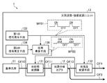
- FIG. 1 is a block diagram showing a configuration of a laser radar apparatus according to Embodiment 1 of the present invention.
- the laser radar apparatus includes an optical transmission unit 1, an optical amplifier 2, an optical circulator 3, an optical antenna unit (optical antenna) 4, an optical heterodyne receiver 5, a signal processing unit 6, and a display means 7.
- thick lines OF1 to OF7 indicate optical signal transmission paths, and thin lines indicate electrical signal transmission paths.
- the optical transmission unit 1 outputs local oscillation light that is continuous oscillation / constant polarization (continuous oscillation light) and transmission light that has been subjected to pulse modulation in which ON / OFF periods are periodically repeated.
- This optical transmission unit includes a reference light source 11, an optical path branching coupler 12, and an optical frequency / intensity modulation unit 13.
- the reference light source 11 generates light having a single wavelength (single frequency) and continuous oscillation and constant polarization.
- the light generated by the reference light source 11 is transmitted to the optical path branching coupler 12 through the transmission path OF1.
- the optical path branching coupler 12 branches the light from the reference light source 11 into two while maintaining the polarization state.
- One light branched into two by this optical path branching coupler 12 is transmitted as local oscillation light to the optical heterodyne receiver 5 via the transmission line OF3, and the other light is transmitted as light as a seed light for transmission via the transmission line OF2. It is transmitted to the frequency / intensity modulation unit 13.
- the optical frequency / intensity modulation unit 13 applies an offset frequency to the light from the optical path branching coupler 12 and performs pulse modulation in which the ON / OFF period is periodically repeated.
- the configuration of the optical frequency / intensity modulation unit 13 will be described later.
- the light subjected to frequency / intensity modulation by the optical frequency / intensity modulation unit 13 is transmitted as transmission light to the optical amplifier 2 through the transmission line OF4.
- the optical amplifier 2 optically amplifies transmission light from the optical frequency / intensity modulation unit 13 of the optical transmission unit 1. At this time, the optical amplifier 2 performs optical amplification by releasing the energy accumulated during the pulse OFF period of the transmission light during the pulse ON period using the accumulation action of the amplification medium.
- the transmission light optically amplified by the optical amplifier 2 is transmitted to the optical circulator 3 through the transmission line OF5.
- the optical circulator 3 switches an output destination transmission path according to input light (transmitted light or received light).
- the optical circulator 3 transmits the transmission light to the optical antenna unit 4 via the transmission path OF6.
- the optical circulator 3 transmits the received light to the optical heterodyne receiver 5 via the transmission path OF7.
- the optical antenna unit 4 emits transmission light transmitted by the optical circulator 3 to a space (observation space) and receives backscattered light from the space with respect to the transmission light as reception light.
- the beam emission direction is set to a specific direction while the transmission light is enlarged to a specific beam diameter, and then emitted to the space.
- the transmission light emitted into the space by the optical antenna unit 4 is backscattered by a scattering target (for example, aerosol moving at the same speed as the wind speed) in the observation space, and undergoes a Doppler frequency shift according to the moving speed of the scattering target. .
- the back scattered light from the scattering target is received by the optical antenna unit 4.
- the received light received by the optical antenna unit 4 is transmitted to the optical circulator 3 through the transmission path OF6.
- the optical heterodyne receiver 5 performs optical heterodyne detection using the local oscillation light from the optical path branching coupler 12 of the optical transmission unit 1 and the reception light from the optical antenna unit 4 via the optical circulator 3. That is, the optical heterodyne receiver 5 optically combines the locally oscillated light and the received light (backscattered light) to perform photoelectric conversion, thereby generating a beat signal having a difference frequency between the backscattered light and the locally oscillated light. Is output. The beat signal output by the optical heterodyne receiver 5 is transmitted to the signal processing unit 6.
- the signal processing unit 6 performs frequency analysis on the beat signal from the optical heterodyne receiver 5. At this time, the signal processing unit 6 first AD-converts the beat signal at a specific sampling rate. Then, the AD converted beat signal is divided for each reception gate (time gate) width corresponding to the pulse width of the transmission light. Then, the beak value, the spectrum width, the SNR, and the like of the power spectrum obtained for each reception gate are calculated by performing fast Fourier transform on the divided beat signals for each reception gate.
- time gate time gate
- the beak value, the spectrum width, the SNR, and the like of the power spectrum obtained for each reception gate are calculated by performing fast Fourier transform on the divided beat signals for each reception gate.
- each reception gate corresponds to the measurement distance, a distribution of Doppler frequency corresponding to the wind speed in the line-of-sight direction for each observation distance can be obtained by the above calculation.
- the signal processing unit 6 has a function of outputting a command value for the observation line of sight to the optical antenna unit 4. Therefore, by storing the measurement values of the observation distance and the wind speed for each line-of-sight direction obtained according to this command value, it is possible to estimate the three-dimensional distribution of the wind speed and obtain the wind direction and the wind speed distribution for each observation distance by vector calculation. .
- the analysis result by the signal processing unit 6 is transmitted to the display means 7.
- the display means 7 displays the analysis result by the signal processing unit 6.
- the optical frequency / intensity modulation unit 13 includes an optical phase modulator 131, an optical intensity modulation unit 132, a first signal generation unit 133, and a second signal generation unit 134.
- the first signal generating unit 133 is connected to the light intensity modulating unit 132
- the second signal generating unit 134 is connected to the optical phase modulator 131.
- the optical phase modulator 131 performs phase modulation on the light from the optical path branching coupler 12 in accordance with the sawtooth drive signal WF02 generated by the second signal generating means 134 to give an offset frequency.
- the transmission light phase-modulated by the optical phase modulator 131 is transmitted to the light intensity modulation means 132 via the transmission line OF8.
- the light intensity modulation unit 132 performs pulse modulation on the light from the optical phase modulator 131 in accordance with the pulse modulation drive signal WF01 generated by the first signal generation unit 133 to generate transmission light.
- the light intensity modulation means 132 responds to the pulse width (several hundreds [ns] to 1 [ ⁇ s]) and the repetition frequency (several [kHz] to several tens [kHz]) required for the laser radar device. Anything is acceptable.
- intensity modulators such as Mach Zehnder type LN modulators and EA (Electro Absorption) modulators
- optical amplifiers such as semiconductor optical amplifiers and optical fiber amplifiers
- optical switches such as MEMS optical switches are conceivable. .
- the first signal generator 133 drives the light intensity modulator 132 by generating a pulse modulation drive signal WF01 that repeats the ON / OFF period periodically required for the transmission light of the pulse type laser radar device. is there.
- the second signal generation means 134 has an amplitude 2 mV ⁇ corresponding to an integral multiple (m times) of the driving voltage 2V ⁇ necessary for obtaining the modulation phase 2 ⁇ (360 °) of the optical phase modulator 131 and a constant period T.
- a sawtooth drive signal WF02 is generated to drive the optical phase modulator 131.
- the reference light source 11 generates light having a single wavelength of continuous oscillation and constant polarization
- the optical path branching coupler 12 converts the light into a polarization state.
- the other is transmitted to the optical heterodyne receiver 5 as local oscillation light, and the other is transmitted to the optical frequency / intensity modulation unit 13 as seed light for transmission.
- the optical frequency / intensity modulation unit 13 assigns an offset frequency f ofs to the light from the optical path branching coupler 12, and performs pulse modulation by periodically repeating the ON / OFF period, thereby transmitting light.
- the frequency ⁇ of light from the optical path branching coupler 12 is 195 [THz]
- the offset frequency f ofs is several tens [MHz] to several hundred ⁇ MHz]
- the pulse width is several hundreds. About [ns] to 1 [ ⁇ s] is used. Details of the operation of the optical frequency / intensity modulation unit 13 will be described later.
- the optical amplifier 2 optically amplifies the light from the optical frequency / intensity modulation unit 13, and the optical antenna unit 4 uses the light as transmission light and expands it to a specific beam diameter while setting the beam emission direction to a specific direction. Set and release into space.
- the transmission light emitted by the optical antenna unit 4 is backscattered by the scattering target in the observation space and undergoes a Doppler frequency shift corresponding to the moving speed of the scattering target.
- the optical antenna unit 4 receives the backscattered light as received light.
- the optical heterodyne receiver 5 performs optical heterodyne detection using the local oscillation light from the optical transmission unit 1 and the reception light from the optical antenna unit 4 via the optical circulator 3. That is, the optical heterodyne receiver 5 optically combines the locally oscillated light and the received light (backscattered light) to perform photoelectric conversion, thereby generating a beat signal having a difference frequency between the backscattered light and the locally oscillated light. Is output.
- the frequency f of the beat signal obtained by the optical heterodyne receiver 5 is expressed by the following equation (1).
- f ofs represents the offset frequency of the optical frequency / intensity modulation unit 13
- f DOP represents the Doppler frequency due to the wind speed.
- the beat signal has a center frequency of 100 [MHz] or less.
- This beat signal is continuously obtained immediately after the transmission light is emitted.
- the distance L to the scattering target can be calculated from the arrival time ⁇ t until the received light is received after the transmitted light is radiated, as shown in the following equation (2).
- c represents the speed of light.
- the signal processing unit 6 performs frequency analysis on the beat signal from the optical heterodyne receiver 5.
- the analysis result by the signal processing unit 6 is stored in a data storage unit (not shown) in the laser radar device, and necessary information is displayed and provided to the user by the display means 7.
- the second signal generating means 134 is an integral multiple (m times) of the drive voltage 2V ⁇ necessary for obtaining the modulation phase 2 ⁇ (360 °) of the optical phase modulator 131.
- a sawtooth drive signal WF02 having a constant period T and an amplitude of 2 mV ⁇ .
- the optical phase modulator 131 performs phase modulation on the transmission light from the optical path branching coupler 12 according to the sawtooth wave drive signal WF02, and gives an offset frequency.
- a phase ⁇ (t) having a constant rate of change 2m ⁇ / T [rad / s] with respect to time t is output from the optical phase modulator 131 as shown in the following equation (3).
- mod (t, T) indicates a remainder when time t is divided by period T.
- the frequency f can be defined by time differentiation of the phase ⁇ as in the following equation (4).
- the optical phase modulator 131 sets the reciprocal of the period T of the sawtooth drive signal WF02 as shown in the following equation (5).
- a proportional offset frequency f ofs can be obtained.
- FIG. 3 shows an actual measurement example of the sawtooth drive signal WF02 input to the optical phase modulator 131 and the beat signal obtained by the optical heterodyne receiver 5 in order to realize a frequency shift of 1 [kHz].
- the lower thin line shows the waveform of the sawtooth drive signal WF02
- the upper thick line shows the waveform of the beat signal.
- the amplitude of the sawtooth drive signal WF02 is set to 7 [V] which is the 2V ⁇ voltage (360 °) of the optical phase modulator 131, and the period T is set to 1 [ms].
- a sine wave having a constant period of 1 [ms] is obtained as a beat signal, and it can be seen that a desired frequency shift of 1 [kHz] is obtained.
- the first signal generating means 133 generates a pulse modulation drive signal WF01 that repeats the OF / OFF period periodically required for the transmission light of the pulse type laser radar device. Then, the light intensity modulation means 132 performs pulse modulation on the light from the optical phase modulator 131 in accordance with the pulse modulation drive signal WF01 to obtain transmission light.
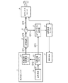
- FIG. 4 shows a timing diagram of each light in the laser radar apparatus according to the first embodiment.
- transmission light 101 having a specific pulse width and repetition period is output by optical phase modulator 131 and light intensity modulation means 132.
- the frequency of the transmission light 101 is represented by ⁇ + f ofs, where ⁇ is the output frequency of the reference light source 11 and f ofs is the offset frequency by the optical phase modulator 131.
- the received light 102 is backscattered light from an aerosol that moves by riding in the air in the atmosphere, and is continuously collected during the pulse OFF period of the transmitted light 101.
- FIG. 4 shows the received light 102 corresponding to a specific distance range for the sake of explanation, it is actually collected continuously during the pulse OFF period of the transmitted light 101.
- Frequency of the received light 102, since the Doppler frequency f w according to the wind velocity is applied is represented by ⁇ + f ofs + f w.
- the local oscillation light 103 is output as a continuous wave in time, and the frequency thereof matches the frequency ⁇ of the reference light source 11.
- the received light 102 and the local oscillation light 103 are optically combined, then photoelectrically converted, and a beat signal f ofs + f having a difference frequency between the reception light 102 and the local oscillation light 103 is obtained.
- Output w .
- the time-series data of the optical heterodyne signal (beat signal) spectrum is obtained as a spectrum detuned by Doppler frequency f w from the center frequency f ofs.
- the optical phase modulator 131 used in the present invention utilizes a change in the refractive index of the propagation optical path due to the electro-optic effect of the LN crystal. Therefore, the propagation effect for the spatial separation of the diffraction effect and the diffracted light as in the AO modulator is unnecessary, and it can contribute to miniaturization and low power consumption. Further, by shortening the propagation length, it is possible to integrate adjacent to the reference light source 11.
- optical phase modulator 131 and the optical intensity modulation means 132 are commercially available with high-speed response (cut-off frequency ⁇ several tens [GHz]) for optical communication. For this reason, it is possible to contribute to improvement in reliability and cost reduction as compared with a conventional configuration using an AO modulator and a modulation driving device that are not widely used for optical communication.
- the diffraction angle changes depending on the frequency (center wavelength) of the reference light source 11, resulting in a change in insertion loss and a line penalty.
- the allowable range for the wavelength variation and wavelength setting range of the reference light source 11 can be expanded. This eliminates the need for equipment for wavelength selection, testing, and stabilization of the reference light source 11 and contributes to cost reduction.
- the blocks inside the optical transmission unit 1 can be integrated into one module by butt joint connection without optical fiber connection.
- an optical circulator and a total reflection mirror for reciprocating the light intensity modulation unit have been required.
- the optical circulator and the total reflection mirror are not necessary, so that the number of parts can be reduced and the cost can be reduced.
- the center frequency of the observation signal matches the center frequency f ofs .
- the transmission light 101 is ideally turned ON / OFF and there is no leakage light during the pulse OFF period. For this reason, the optical heterodyne signal does not include an unnecessary beat signal associated with leaked light. Therefore, the signal processing unit 6, it is only necessary to signal processing by cutting out only the existence range 104 of the Doppler frequency f w filter. Note that the configuration in the case where leakage light in the pulse OFF period exists in the transmission light 101 will be described in detail in the second and subsequent embodiments.
- the optical phase modulator 131 and the light intensity modulator 132 are provided as means for realizing addition of an offset frequency and pulse modulation necessary as functions on the transmission side of the laser radar device. Since the frequency shift and pulsing required on the transmission side without using an AO modulator, the device can be reduced in size and integrated, and the reliability can be improved by reducing the number of parts. Cost reduction can be achieved.
- FIG. 5 is a block diagram showing the configuration of the optical transmission unit 1 according to the second embodiment of the present invention.
- the optical transmission unit 1 according to the second embodiment shown in FIG. 5 is subordinately connected to the optical frequency / intensity modulation unit 13 of the optical transmission unit 1 according to the first embodiment shown in FIG.
- the second light intensity modulation means 135 is added.
- Other configurations are the same, and the same reference numerals are given and only different portions will be described.
- the first signal generation means 133 generates a pulse modulation drive signal WF01 that repeats the OF / OFF period periodically required for the transmission light of the pulse type laser radar device to generate the light intensity modulation means 132 and the second light intensity modulation means 132.
- the light intensity modulating means 135 is driven.
- the second light intensity modulation means 135 performs pulse modulation on the transmission light from the light intensity modulation means 132 in accordance with the pulse modulation drive signal WF01 generated by the first signal generation means 133 to generate transmission light. is there. At this time, the second light intensity modulation unit 135 performs synchronous modulation together with the light intensity modulation unit 132 to suppress leakage light in the pulse OFF period of the transmission light.
- the second light intensity modulating means 135 has a pulse width (several hundreds [ns] to 1 [ ⁇ s]) and a repetition frequency (several [kHz] to several tens [kHz]) required for the laser radar device. Any means for responding can be used. For example, in addition to intensity modulators such as Mach Zehnder type LN modulators and EA modulators, optical amplifiers such as semiconductor optical amplifiers and optical fiber amplifiers, optical switches such as MEMS optical switches, and the like are conceivable.
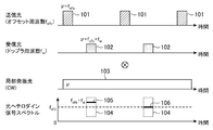
- FIG. 6 shows a timing diaphragm of each light when the extinction characteristic of the pulse OFF period by the light intensity modulator 23 in the second embodiment is not ideal.
- transmission light 101 having a specific pulse width and repetition period is output during the pulse ON period, while leakage light 201 is output during the pulse OFF period.
- the leaked light 201 is then amplified by the optical amplifier 2. Then, the crosstalk from the transmission path OF5 of the optical circulator 3 to the transmission path OF7, and the reflection of the internal components of the optical antenna unit 4 at the rear stage of the transmission path OF6, the cross of the transmission light 101 (pulse ON period) to the reception optical path.
- the light 202 enters the optical heterodyne receiver 5 as leakage light 203 into the reception optical path of the talk 202 and leakage light 201 (pulse OFF period).
- the leakage light 203 to the reception optical path is a direct light leakage of the transmission light 101 or reflection from a fixed object, the leakage light 203 has the same frequency ⁇ + f ofs as the transmission light 101 (pulse ON period). For this reason, in the optical heterodyne receiver 5, the leakage light 203 to the reception optical path interferes with the local oscillation light 103 to generate an unnecessary beat signal 204.
- This unnecessary beat signal 204 has f ofs which is a difference frequency between the leakage light 203 and the local oscillation light 103 in the reception optical path, and this always exists in time.
- the leakage light 201 in the pulse OFF period is suppressed by synchronously modulating the light intensity modulation means 132 together with the second light intensity modulation means 135.
- FIG. 7 shows a timing diaphragm of each light when the second light intensity modulation unit 135 in the second embodiment is synchronously modulated together with the light intensity modulation unit 132.
- the second light intensity modulation means 135 is synchronously modulated together with the light intensity modulation means 132, so that the leakage light 201 of the transmission light 101 in the pulse OFF period is leaked. Is suppressed.
- the crosstalk 202 to the reception optical path of the transmission light 101 (pulse ON period) and the reception light 102 by wind speed Doppler are obtained as the reception light.
- the optical heterodyne signal spectrum includes the crosstalk 202 of the transmission light 101 (pulse ON period), the beat signal 205 of the local oscillation light 103, and the wind speed. Only the Doppler frequency f w (peak frequency 105, 106, existence range 104) by appears in the spectrum.
- the beat signal 205 between the crosstalk 202 of the transmission light 101 (pulse ON period) and the local oscillation light 103 corresponds to a signal at a distance of 0 m that is not necessary in the laser radar device, and therefore may be rejected in terms of time. .
- the unnecessary beat signal 205 can be suppressed from the optical heterodyne signal spectrum during the pulse OFF period in which wind speed observation is desired, so that accurate wind speed Doppler detection is possible.
- the center frequency increases as the number of stages increases. Therefore, it is necessary to increase the frequency of components used in the optical heterodyne receiver 5 and to increase the signal sampling rate in the signal processing unit 6.
- the center frequency does not change, so that the signal processing at the subsequent stage can be used without change.
- an optical amplifier such as a semiconductor optical amplifier or an optical fiber amplifier may be used for all or a part thereof.
- insertion loss optical path loss
- the laser radar apparatus since a plurality of light intensity modulation means 132 and 135 are connected in cascade to perform synchronous modulation, in addition to the effects of the first embodiment, the laser radar apparatus It is possible to realize a high pulse ON / OFF extinction ratio necessary as performance on the transmission side. Further, since both the light intensity modulation means 132 and the second light intensity modulation means 135 have no wavelength dependence, the tolerance for the wavelength variation of the reference light source 11 and the wavelength setting range compared to the configuration using the conventional AO modulator. The range can be expanded.
- FIG. 8 is a block diagram showing the configuration of the optical transmission unit 1 according to the third embodiment of the present invention.
- the optical transmission unit 1 according to the third embodiment shown in FIG. 8 has signal multiplying means (third signal generating means) added to the optical frequency / intensity modulation unit 13 of the optical transmission unit 1 according to the first embodiment shown in FIG. 136 is added.
- signal multiplying means third signal generating means
- the signal multiplication unit 136 includes a portion corresponding to the pulse ON period of the pulse modulation drive signal WF01 generated by the first signal generation unit 133 in the sawtooth drive signal WF02 generated by the second signal generation unit 134.
- the cut-out sawtooth wave drive signal WF03 is output, and the optical phase modulator 131 is driven in place of the second signal generating means 134.
- the optical phase modulator 131 performs phase modulation on the light from the optical path branching coupler 12 according to the burst-like sawtooth drive signal WF03 output from the signal multiplying unit 136 to give an offset frequency.
- transmission light output from the transmission path OF04 is the pulse ON period is added offset frequency f ofs, not added offset frequency in the pulse OFF periods.
- an offset frequency is added to the leakage light.
- the offset frequency is not added to the leaked light.
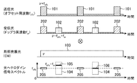
- FIG. 9 shows a timing diagram of each light in the laser radar device according to the third embodiment.
- transmission light 101 having a specific pulse width and repetition period is output during the pulse ON period, while leakage light 301 is output during the pulse OFF period.
- the leaked light 301 is then amplified by the optical amplifier 2. Then, the crosstalk from the transmission path OF5 of the optical circulator 3 to the transmission path OF7, and the reflection of the internal components of the optical antenna unit 4 at the rear stage of the transmission path OF6, the cross of the transmission light 101 (pulse ON period) to the reception optical path.
- the light 302 enters the optical heterodyne receiver 5 as leakage light 303 to the reception optical path of the talk 302 and leakage light 301 (pulse OFF period).
- the frequency of the crosstalk 302 during the pulse ON period is ⁇ + f ofs
- the frequency of the leakage light 303 to the reception optical path of the leakage light 301 (pulse OFF period) is ⁇ because no offset frequency is added to the pulse OFF period. is there.
- an unnecessary beat signal 304 generated by the crosstalk 302 and the local oscillation light 103 during the pulse ON period appears at the f ofs that is the center frequency only during the pulse ON period.
- an unnecessary beat signal 305 generated by the leakage light 303 and the local oscillation light 103 during the pulse OFF period appears in the baseband (frequency 0).
- the Doppler signal (peak frequency 105, the existence range 104) frequency f ofs + f w is away on unwanted beat signals 304, 305 and the spectrum of Therefore, both of them can be electrically separated.
- the pulse modulation drive signal WF01 generated by the first signal generation unit 133 is selected. Since a burst-like sawtooth drive signal cut out from the portion corresponding to the pulse ON period is output, a signal multiplier 136 for driving the optical phase modulator 131 is provided in place of the second signal generator 134.
- the Doppler signal due to the wind speed can be easily separated on the spectrum from the unnecessary beat signals 304 and 305, so that the light intensity modulation is performed.
- the performance requirement for the ON / OFF extinction ratio of the means 132 can be relaxed, which can contribute to cost reduction.
- the combination of burst frequency shift and pulse modulation in the third embodiment is that the conventional AO modulator has a spatial relationship between the output light with the frequency shift added and the output port with no output light added. Therefore, it cannot be realized as it is. That is, a separate means for switching the 0th-order optical output port (without frequency shift) and the first-order optical output port (with frequency shift) of the AO modulator in synchronization with the pulse output is necessary, and an increase in insertion loss or synchronization shift is required.
- the device has a large disadvantage and an increase in power consumption. Further, it is possible to prevent an increase in insertion loss due to the multi-stage light intensity modulation unit as in the conventional example, which contributes to a reduction in power consumption.
- both the light intensity modulation means 132 and the second light intensity modulation means 135 have no wavelength dependency, so that the wavelength of the reference light source 11 is larger than that of the conventional configuration using AO.
- the allowable range with respect to fluctuations and the wavelength setting range can be expanded.
- FIG. 10 is a block diagram showing the configuration of the optical transmission unit 1 according to Embodiment 4 of the present invention.
- the optical transmission unit 1 according to the fourth embodiment illustrated in FIG. 10 is configured such that the position of the optical phase modulator 131 of the optical transmission unit 1 according to the third embodiment illustrated in FIG. 8 is determined between the reference light source 11 and the optical path branching coupler 12. It was changed in between.
- Other configurations are the same, and the same reference numerals are given and only different portions will be described.
- the optical phase modulator 131 performs phase modulation on the light from the reference light source 11 according to the burst sawtooth drive signal WF03 output from the signal multiplier 136 to give an offset frequency.
- the light phase-modulated by the optical phase modulator 131 is transmitted to the optical path branching coupler 12 via the transmission path OF11.
- the optical path branching coupler 12 branches the light from the optical phase modulator 131 into two while maintaining the polarization state.
- the light intensity modulation unit 132 performs pulse modulation on the light from the optical path branching coupler 12 according to the pulse modulation drive signal WF01 generated by the first signal generation unit 133 to generate transmission light.
- the presence / absence change of the offset frequency corresponding to the pulse ON / OFF period is also added to the local oscillation light.
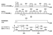
- FIG. 11 shows a timing diagram of each light in the laser radar apparatus according to the fourth embodiment.
- transmission light 101 having a specific pulse width and repetition period is output during the pulse ON period, while leakage light 301 is output during the pulse OFF period.
- the leaked light 301 is then amplified by the optical amplifier 2. Then, the crosstalk from the transmission path OF5 of the optical circulator 3 to the transmission path OF7, and the reflection of the internal components of the optical antenna unit 4 at the rear stage of the transmission path OF6, the cross of the transmission light 101 (pulse ON period) to the reception optical path.
- the light 302 enters the optical heterodyne receiver 5 as leakage light 303 to the reception optical path of the talk 302 and leakage light 301 (pulse OFF period).
- the frequency of the crosstalk 302 during the pulse ON period is ⁇ + f ofs
- the frequency of the leakage light 303 to the reception optical path of the leakage light 301 (pulse OFF period) is ⁇ because no offset frequency is added to the pulse OFF period. is there.
- the frequency of the local oscillation light 103 is ⁇ + f ofs (pulse ON period 401) during the pulse ON period and ⁇ during the pulse OFF period (pulse OFF period 402), as in the transmission light 101. ).
- an unnecessary beat signal 403 generated by the crosstalk 302 in the pulse ON period and the pulse ON period 401 of the local oscillation light 103, and the leaked light 303 and the local oscillation light in the pulse OFF period are generated.
- Any unnecessary beat signal 404 generated by the 103 pulse OFF period 402 appears in the baseband (frequency 0).
- the Doppler signal (peak frequencies 105, 106, existence range 104) due to the wind speed exists near the center frequency.
- the unnecessary beat signals 403 and 404 are separated from each other on the spectrum, so that the two can be electrically separated.
- the phase modulation by the burst-like sawtooth drive signal WF03 synchronized with the transmission light is performed on the transmission light and the local oscillation light.
- the Doppler signal due to the wind speed can be easily separated on the spectrum from the unnecessary beat signals 403 and 404.
- the performance requirement for the ON / OFF extinction ratio can be relaxed, which can contribute to cost reduction.
- the configuration of the fourth embodiment it is possible to shift the unnecessary beat signal 403 in the pulse ON period to the baseband as compared with the configuration of the third embodiment. Therefore, it is possible to avoid the leakage light from being mixed immediately after the pulse OFF period (closest distance range) in the case where a temporal jitter error exists in the pulse timing. For this reason, erroneous detection in wind speed estimation in the closest distance range can be avoided, and wind speed measurement accuracy can be improved.
- both the light intensity modulation means 132 and the second light intensity modulation means 135 have no wavelength dependence, so that the reference light source can be compared with a configuration using a conventional AO modulator.
- the allowable range for the 11 wavelength fluctuations and the wavelength setting range can be expanded.
- Embodiment 5 shows a case where one reference light source 11 and one optical antenna unit 4 are used.
- Embodiment 5 shows a case where the observation space is switched using a plurality of reference light sources 11a and 11b having different wavelengths and a plurality of optical antenna units 4a and 4b corresponding to the respective wavelengths.
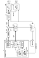
- FIG. 12 is a block diagram showing the configuration of the laser radar apparatus according to Embodiment 5 of the present invention.
- the laser radar device according to the fifth embodiment shown in FIG. 12 includes the reference light source 11 and the optical antenna unit 4 of the laser radar device according to the first embodiment shown in FIG.
- the wavelength branching coupler 8 and the wavelength multiplexing coupler 14 are added to the optical antenna units 4a and 4b.
- Other configurations are the same, and the same reference numerals are given and only different portions will be described.
- the first reference light source 11a generates light that is a continuous wave / constantly polarized light having a center wavelength (frequency) ⁇ 1.
- the light generated by the first reference light source 11a is transmitted to the wavelength multiplexing coupler 14 through the transmission line OF13.
- the second reference light source 11b generates light that is a continuous wave / constantly polarized light having a center wavelength (frequency) ⁇ 2.
- the light generated by the second reference light source 11b is transmitted to the wavelength multiplexing coupler 14 through the transmission line OF14.
- the wavelength multiplexing coupler 14 wavelength-multiplexes the light from the first and second reference light sources 11a and 11b.
- the light wavelength-multiplexed by the wavelength multiplexing coupler 14 is transmitted to the optical path branching coupler 12 via the transmission path OF15.
- the optical path branching coupler 12 branches the light from the wavelength multiplexing coupler 14 into two while maintaining the polarization state.
- the wavelength branching coupler 8 branches the transmission light from the optical circulator 3 for each wavelength.
- the transmission light branched for each wavelength by the wavelength branching coupler 8 is transmitted to the corresponding first and second optical antenna units 4a and 4b via the transmission lines OF17 and OF18.
- the first optical antenna unit 4a corresponds to the first reference light source 11a, emits the transmission light having the center wavelength ⁇ 1 from the wavelength branching coupler 8 into the space, and emits the backscattered light from the space with respect to the transmission light. It is received as received light.
- the received light received by the first optical antenna unit 4a is transmitted to the optical circulator 3 through the transmission lines OF16 and 17.
- the second optical antenna unit 4b corresponds to the second reference light source 11b, emits the transmission light having the center wavelength ⁇ 2 from the wavelength branching coupler 8 to the space, and emits the backscattered light from the space with respect to the transmission light. It is received as received light.
- the received light received by the second optical antenna unit 4b is transmitted to the optical circulator 3 through the transmission lines OF16 and 17.
- FIG. 12 shows an example of a configuration in which the position of the optical path branching coupler 12 is in front of the optical frequency / intensity modulation unit 13 and no frequency shift is given to local oscillation light.
- the present invention is not limited to this.
- the optical path branching coupler 12 is installed after the optical phase modulator 131 driven by the sawtooth drive signal WF03.
- the local oscillation light may be configured to add a frequency shift during the pulse ON period.
- the transmission light output from the optical transmission unit 1 via the transmission line OF4 is amplified by the optical amplifier 2 and passed through the optical circulator 3 as in the configuration of FIG. It is transmitted to the transmission line OF16.
- the transmission light is transmitted from the transmission line OF6 to the wavelength branching coupler 8, and the optical path is switched for each wavelength of the first and second reference light sources 11a and 11b, corresponding to the wavelength ⁇ 1 from the first reference light source 11a.
- the transmitted light is transmitted to the first optical antenna unit 4a, and the light corresponding to the wavelength ⁇ 2 from the second reference light source 11b is transmitted to the second optical antenna unit 4b.
- the observation space can be switched by wavelength switching and measurement can be performed.
- a time-series signal for wavelength selection indicating which one of the first reference light source 11a or the second reference light source 11b is selected at each time is the optical transmission unit 1. Sent to. At the same time, the signal processing unit 6 records and stores the wavelength selection time series signal together with the measured time series data of the Doppler signal. This data is used to identify which one of the first optical antenna unit 4a and the second optical antenna unit 4b is selected in the analysis of the Doppler signal.
- the observation spaces are switched using the plurality of reference light sources 11a and 11b having different wavelengths and the plurality of optical antenna units 4a and 4b corresponding to the respective wavelengths. Since configured, the plurality of optical antenna units 4a and 4b are installed and fixed in advance in different observation spaces, and the observation spaces can be switched by electrically switching the wavelengths. Thereby, the observation space can be switched at high speed without mechanical drive.
- optical antenna units 4a and 4b are fixed at different ground positions with the zenith direction as the center of the field of view, and the optical antenna units 4a and 4b are switched by wavelength switching, so that the height distribution of wind direction and wind speed at two points can be obtained by one laser. It can be measured with a radar device.
- the optical frequency / intensity modulation unit 13 is changed to the wavelength. It was necessary to install every.
- one optical frequency / intensity modulation unit 13 can be used in common. Therefore, the number of parts can be reduced, contributing to cost reduction.
- variable wavelength laser array that has been put into practical use in recent optical communication equipment
- a module in which 12 or more reference light sources and wavelength multiplexing couplers are already integrated is commercially available. Therefore, by using this variable wavelength laser array for optical communication, not only can the element be miniaturized, but also a component that has been tested for reliability as a communication component and has a cost reduction effect due to mass production can be used. Therefore, costs including development costs can be reduced.
- the invention of the present application can be freely combined with each embodiment, modified with any component in each embodiment, or omitted with any component in each embodiment. .
- the laser radar apparatus performs the frequency shift and pulsing necessary on the transmission side without using an AO modulator, thereby reducing the size and integration of the apparatus and improving the reliability and cost by reducing the number of parts.
- it is suitable for use in a laser radar device that remotely measures the wind direction and wind speed in a weather space.
Abstract
A light transmission unit (1) is provided with: a light phase modulator (131) for phase modulating continuous wave light; a light intensity modulation means (132) for pulse modulating the phase-modulated light to generate transmission light; a first signal generating means (133) for generating a pulse-modulated drive signal, which has periodically repeating on and off periods, to drive the light intensity modulation means (132); and a second signal generating means (134) for generating a sawtooth wave drive signal to drive the light phase modulator (131), said sawtooth wave drive signal having a constant period and an amplitude that is equivalent to an integral multiple of the drive voltage necessary for acquiring a phase of modulation of 2π at the light phase modulator (131).
Description
この発明は、例えば気象空間における風向風速を遠隔計測するレーザレーダ装置に関するものである。
The present invention relates to a laser radar device that remotely measures, for example, the wind direction and wind speed in a weather space.
特許文献1には、走査光軸に沿ってパルス状の送信光を送信し、この送信光に基づく受信光に含まれるドップラ周波数光信号を分析して、走査光軸の方位における風速等を計測するレーザレーダ装置が開示されている。このレーザレーダ装置は、ドップラ周波数光信号をドップラ周波数電気信号に変換し、このドップラ周波数電気信号を分析する分析回路を備えている。
In Patent Document 1, pulsed transmission light is transmitted along the scanning optical axis, and the Doppler frequency optical signal included in the reception light based on the transmission light is analyzed to measure the wind speed and the like in the direction of the scanning optical axis. A laser radar device is disclosed. This laser radar device includes an analysis circuit that converts a Doppler frequency optical signal into a Doppler frequency electrical signal and analyzes the Doppler frequency electrical signal.
また、風向風速を計測するレーザレーダ装置では、送信光をパルス化するため、送信器内に光強度変調ユニットを用いている。しかしながら、この光強度変調ユニットに用いる音響光学変調器(AO(Acousto Optic)変調器)では、変調用の超音波信号が残響することに起因するキャリアリーク光が発生する。そして、このキャリアリーク光が光ヘテロダイン受信機で不要なビート信号を誘発する。
この不要なビート信号は計測したいドップラ信号と周波数領域で重なるため、ドップラ周波数を正しく推定できなくなるという不都合がある。 Further, in a laser radar device that measures the wind direction and wind speed, a light intensity modulation unit is used in the transmitter in order to pulse transmission light. However, in an acousto-optic modulator (AO (Acousto Optic) modulator) used in this light intensity modulation unit, carrier leak light is generated due to reverberation of an ultrasonic signal for modulation. The carrier leak light induces an unnecessary beat signal in the optical heterodyne receiver.
Since this unnecessary beat signal overlaps the Doppler signal to be measured in the frequency domain, there is a disadvantage that the Doppler frequency cannot be estimated correctly.
その対策として、特許文献1では、光強度変調ユニットの入力端の前段に光サーキュレータを設置し、光強度変調ユニットの出力端の後段に全反射ミラーを設置している。これにより、光強度変調ユニットを往復伝搬させて、パルスOFF期間のキャリアリーク光を低減することができる。
As a countermeasure, in Patent Document 1, an optical circulator is installed in front of the input end of the light intensity modulation unit, and a total reflection mirror is installed in the rear stage of the output end of the light intensity modulation unit. Thereby, it is possible to reduce the carrier leak light during the pulse OFF period by reciprocating the light intensity modulation unit.
従来の風向風速を計測するレーザレーダ装置では、パルスOFF期間のキャリアリーク光を低減するために、光強度変調ユニットを往復伝搬させるための光サーキュレータおよび全反射ミラーが必要である。そのため、部品点数が増加し、また光軸調整点数も増加する結果、コスト低減や信頼性において課題があった。
Conventional laser radar devices that measure wind direction and wind speed require an optical circulator and a total reflection mirror for reciprocating the light intensity modulation unit in order to reduce carrier leak light during the pulse OFF period. As a result, the number of parts increases and the number of optical axis adjustments also increases, resulting in problems in cost reduction and reliability.
また、光強度変調ユニットを往復伝搬させると、挿入損失が増加する。そのため、この挿入損失を補てんするために、前段の基準光源のパワーを増強するか、後段の光増幅器の利得を増加させる等の対策が必要である。よって、消費電力の低減とコスト低減において課題があった。
Also, when the light intensity modulation unit is propagated back and forth, the insertion loss increases. Therefore, in order to compensate for this insertion loss, it is necessary to take measures such as increasing the power of the reference light source at the front stage or increasing the gain of the optical amplifier at the rear stage. Thus, there are problems in reducing power consumption and cost.
さらに、従来の風向風速を計測するレーザレーダ装置では、走査光軸に沿った方位における風速の正負(向かい風/追い風)を検出するため、パルスON期間に送信光にオフセット周波数を付加する必要がある。そのため、光強度変調ユニットには周波数シフト機能のあるAO変調器が用いられている。
Furthermore, in a conventional laser radar device that measures the wind direction and wind speed, it is necessary to add an offset frequency to the transmitted light during the pulse ON period in order to detect the positive / negative (head wind / tail wind) of the wind speed in the direction along the scanning optical axis. . Therefore, an AO modulator having a frequency shift function is used for the light intensity modulation unit.
このAO変調器は、ガラス基板や音響光学結晶の端面に取り付けたピエゾ等のトランスデューサに高周波電圧を印加することで、媒質内に超音波を励起伝搬させる。媒体内を超音波で振動させると屈折率の粗密の周期構造が生成され、超音波の速度で伝搬する。媒質のトランスデューサの対向端面を超音波吸収帯で無反射終端することで、あたかも位相格子が超音波の速度で一定方向に移動する。
This AO modulator excites and propagates ultrasonic waves in a medium by applying a high-frequency voltage to a transducer such as a piezo attached to the end face of a glass substrate or acousto-optic crystal. When the inside of a medium is vibrated with ultrasonic waves, a periodic structure with a refractive index is formed and propagates at the velocity of the ultrasonic waves. By terminating the opposite end face of the medium transducer with an ultrasonic absorption band without reflection, the phase grating moves in a certain direction at the speed of ultrasonic waves.
AO変調器に光を入射すると、出射光は媒体内に生じた位相格子でのブラッグ回折により進行方向が変化するだけでなく、位相格子の移動に伴いドップラシフトを受ける。トランスデューサに印加する高周波信号をON/OFFすることでパルス光に切り出すと同時に、パルスON期間に一定の周波数シフトを付加することができる。
When light enters the AO modulator, the traveling direction of the emitted light not only changes due to Bragg diffraction in the phase grating generated in the medium, but also undergoes Doppler shift as the phase grating moves. By turning ON / OFF the high-frequency signal applied to the transducer, it can be cut into pulsed light and at the same time, a certain frequency shift can be added to the pulse ON period.
音響光学素子のブラッグ角θは、光の波長λ、オフセット周波数fofs、音響光学素子内での超音波の進行速度vaにより次式で表される。
 Bragg angle θ of the acoustooptic element, the wavelength of light lambda, the offset frequency f ofs, the moving speed v a of the ultrasonic wave in the acousto-optic device is expressed by the following equation.
典型的なAO変調器の例として、λ=1.55[μm],fofs=80[MHz],va=3.63[mm/μs]の場合には、ブラッグ角θは17[mrad]であり約1度に相当する。
As an example of a typical AO modulator, when λ = 1.55 [μm], f ofs = 80 [MHz], and v a = 3.63 [mm / μs], the Bragg angle θ is 17 [mrad]. ], Which corresponds to about 1 degree.
しかしながら上記のレーザレーダ装置に用いられるAO変調器では、ブラッグ回折角が1度以下と小さい。そのため、0次透過光と1次回折光とを光学的に分離するためには少なくとも、30[mm]程度以上は伝搬距離が必要であり、小型集積化には適していなかった。
また、音響光学結晶と入/出射光の光軸をブラッグ回折角に一致するように、各6軸(並進位置、角度)を精密調整する必要があり、組み立て調整費用の低減が困難であった。 However, the AO modulator used in the above laser radar apparatus has a small Bragg diffraction angle of 1 degree or less. For this reason, in order to optically separate the 0th-order transmitted light and the 1st-order diffracted light, a propagation distance of at least about 30 [mm] is required, which is not suitable for miniaturization.
In addition, it is necessary to precisely adjust each of the six axes (translational position and angle) so that the optical axes of the acousto-optic crystal and the incoming / outgoing light coincide with the Bragg diffraction angle, and it is difficult to reduce assembly adjustment costs. .
さらに、ブラッグ角θが光波長λに依存して変化する。そして、ブラッグ角変化による入出力端での光軸ずれ(およびそれに伴う挿入損失の増加)を低減するためには、基準光源の中心波長を一定に制御する必要があり、コストがかかっていた。
Furthermore, the Bragg angle θ changes depending on the light wavelength λ. Further, in order to reduce the optical axis shift (and the accompanying increase in insertion loss) at the input / output end due to the Bragg angle change, it is necessary to control the center wavelength of the reference light source to be constant, which is costly.
この発明は、上記のような課題を解決するためになされたもので、AO変調器を用いずに送信側に必要な周波数シフトとパルス化を実施することで、装置の小型・集積化、部品点数低減による信頼性向上とコスト低減を図ることができるレーザレーダ装置を提供することを目的としている。
The present invention has been made to solve the above-described problems. By implementing the frequency shift and pulsing necessary on the transmission side without using an AO modulator, the device can be reduced in size, integrated, and components. An object of the present invention is to provide a laser radar device capable of improving reliability and reducing cost by reducing the number of points.
この発明に係るレーザレーダ装置は、連続発振光である局部発振光および送信光を出力する光送信ユニットと、光送信ユニットにより出力された送信光を空間に放射し、当該送信光に対する後方散乱光を受信光として受信する光アンテナと、光送信ユニットにより出力された局部発振光および光アンテナにより受信された受信光を用いて光ヘテロダイン検出を行う光ヘテロダイン受信機と、光ヘテロダイン受信機による検出結果を周波数分析する信号処理ユニットとを備えたレーザレーダ装置であって、光送信ユニットは、連続発振光に対して位相変調を行う光位相変調器と、光位相変調器により位相変調された光に対してパルス変調を行い送信光とする光強度変調手段と、周期的にON/OFF期間を繰返すパルス変調駆動信号を発生して光強度変調手段を駆動する第1の信号発生手段と、光位相変調器の変調位相2πを得るために必要な駆動電圧の整数倍に相当する振幅および一定周期を持つ鋸波駆動信号を発生して光位相変調器を駆動する第2の信号発生手段とを備えたものである。
A laser radar device according to the present invention includes an optical transmission unit that outputs local oscillation light and transmission light, which are continuous wave light, and transmission light output by the optical transmission unit to space, and backscattered light with respect to the transmission light Optical heterodyne receiver that performs optical heterodyne detection using the local oscillation light output by the optical transmission unit and the received light received by the optical antenna, and the detection result by the optical heterodyne receiver A laser radar device including a signal processing unit for frequency analysis of the optical transmission unit, wherein the optical transmission unit converts the phase modulation of the continuous wave light into the light phase-modulated by the optical phase modulator. A light intensity modulation means that performs pulse modulation to transmit light and a pulse modulation drive signal that periodically repeats the ON / OFF period are generated. A first signal generating means for driving the light intensity modulating means, and a sawtooth drive signal having an amplitude and a constant period corresponding to an integral multiple of the driving voltage necessary to obtain the modulation phase 2π of the optical phase modulator. And second signal generating means for driving the optical phase modulator.
この発明によれば、上記のように構成したので、AO変調器を用いずに送信側に必要な周波数シフトとパルス化を実施することで、装置の小型・集積化、部品点数低減による信頼性向上とコスト低減を図ることができる。
According to the present invention, since it is configured as described above, the frequency shift and pulsing necessary on the transmission side are performed without using the AO modulator, thereby reducing the size and integration of the device and reducing the number of components. Improvement and cost reduction can be achieved.
以下、この発明の実施の形態について図面を参照しながら詳細に説明する。
実施の形態1.
図1はこの発明の実施の形態1に係るレーザレーダ装置の構成を示すブロック図である。
レーザレーダ装置は、図1に示すように、光送信ユニット1、光増幅器2、光サーキュレータ3、光アンテナユニット(光アンテナ)4、光ヘテロダイン受信機5、信号処理ユニット6および表示手段7から構成されている。なお図1において、太線OF1~OF7は光信号の伝送路を示し、細線は電気信号の伝送路を示している。 Hereinafter, embodiments of the present invention will be described in detail with reference to the drawings.
Embodiment 1 FIG.
FIG. 1 is a block diagram showing a configuration of a laser radar apparatus according toEmbodiment 1 of the present invention.
As shown in FIG. 1, the laser radar apparatus includes anoptical transmission unit 1, an optical amplifier 2, an optical circulator 3, an optical antenna unit (optical antenna) 4, an optical heterodyne receiver 5, a signal processing unit 6, and a display means 7. Has been. In FIG. 1, thick lines OF1 to OF7 indicate optical signal transmission paths, and thin lines indicate electrical signal transmission paths.
実施の形態1.
図1はこの発明の実施の形態1に係るレーザレーダ装置の構成を示すブロック図である。
レーザレーダ装置は、図1に示すように、光送信ユニット1、光増幅器2、光サーキュレータ3、光アンテナユニット(光アンテナ)4、光ヘテロダイン受信機5、信号処理ユニット6および表示手段7から構成されている。なお図1において、太線OF1~OF7は光信号の伝送路を示し、細線は電気信号の伝送路を示している。 Hereinafter, embodiments of the present invention will be described in detail with reference to the drawings.
FIG. 1 is a block diagram showing a configuration of a laser radar apparatus according to
As shown in FIG. 1, the laser radar apparatus includes an
光送信ユニット1は、連続発振・定偏光(連続発振光)である局部発振光と、周期的にON/OFF期間を繰り返したパルス変調を行った送信光とを出力するものである。この光送信ユニットは、基準光源11、光路分岐カプラ12および光周波数・強度変調ユニット13から構成されている。
The optical transmission unit 1 outputs local oscillation light that is continuous oscillation / constant polarization (continuous oscillation light) and transmission light that has been subjected to pulse modulation in which ON / OFF periods are periodically repeated. This optical transmission unit includes a reference light source 11, an optical path branching coupler 12, and an optical frequency / intensity modulation unit 13.
基準光源11は、単一波長(単一周波数)の連続発振・定偏光である光を発生するものである。この基準光源11により発生された光は伝送路OF1を介して光路分岐カプラ12に伝送される。
The reference light source 11 generates light having a single wavelength (single frequency) and continuous oscillation and constant polarization. The light generated by the reference light source 11 is transmitted to the optical path branching coupler 12 through the transmission path OF1.
光路分岐カプラ12は、基準光源11からの光を偏光状態を維持したまま2分岐するものである。この光路分岐カプラ12により2分岐された一方の光は局部発振光として伝送路OF3を介して光ヘテロダイン受信機5に伝送され、他方の光は送信用の種光として伝送路OF2を介して光周波数・強度変調ユニット13に伝送される。
The optical path branching coupler 12 branches the light from the reference light source 11 into two while maintaining the polarization state. One light branched into two by this optical path branching coupler 12 is transmitted as local oscillation light to the optical heterodyne receiver 5 via the transmission line OF3, and the other light is transmitted as light as a seed light for transmission via the transmission line OF2. It is transmitted to the frequency / intensity modulation unit 13.
光周波数・強度変調ユニット13は、光路分岐カプラ12からの光に対して、オフセット周波数を付与し、かつ、周期的にON/OFF期間を繰り返したパルス変調を行うものである。この光周波数・強度変調ユニット13の構成については後述する。この光周波数・強度変調ユニット13により周波数・強度変調された光は送信光として伝送路OF4を介して光増幅器2に伝送される。
The optical frequency / intensity modulation unit 13 applies an offset frequency to the light from the optical path branching coupler 12 and performs pulse modulation in which the ON / OFF period is periodically repeated. The configuration of the optical frequency / intensity modulation unit 13 will be described later. The light subjected to frequency / intensity modulation by the optical frequency / intensity modulation unit 13 is transmitted as transmission light to the optical amplifier 2 through the transmission line OF4.
光増幅器2は、光送信ユニット1の光周波数・強度変調ユニット13からの送信光を光増幅するものである。この際、光増幅器2は、増幅媒体の蓄積作用を利用して送信光のパルスOFF期間に蓄積したエネルギーをパルスON期間に開放することで、光増幅を行う。この光増幅器2により光増幅された送信光は伝送路OF5を介して光サーキュレータ3に伝送される。
The optical amplifier 2 optically amplifies transmission light from the optical frequency / intensity modulation unit 13 of the optical transmission unit 1. At this time, the optical amplifier 2 performs optical amplification by releasing the energy accumulated during the pulse OFF period of the transmission light during the pulse ON period using the accumulation action of the amplification medium. The transmission light optically amplified by the optical amplifier 2 is transmitted to the optical circulator 3 through the transmission line OF5.
光サーキュレータ3は、入力光(送信光または受信光)に応じて、出力先の伝送路を切替えるものである。ここで、光サーキュレータ3は、光増幅器2から送信光が伝送された場合には、当該送信光を伝送路OF6を介して光アンテナユニット4に伝送する。一方、光サーキュレータ3は、光アンテナユニット4から受信光が伝送された場合には、当該受信光を伝送路OF7を介して光ヘテロダイン受信機5に伝送する。
The optical circulator 3 switches an output destination transmission path according to input light (transmitted light or received light). Here, when the transmission light is transmitted from the optical amplifier 2, the optical circulator 3 transmits the transmission light to the optical antenna unit 4 via the transmission path OF6. On the other hand, when the received light is transmitted from the optical antenna unit 4, the optical circulator 3 transmits the received light to the optical heterodyne receiver 5 via the transmission path OF7.
光アンテナユニット4は、光サーキュレータ3により伝送された送信光を空間(観測空間)に放出し、かつ、当該送信光に対する空間からの後方散乱光を受信光として受信するものである。なお、光アンテナユニット4は、送信光を放出する際、当該送信光を特定のビーム径に拡大しつつビームの射出方向を特定方向に設定して空間に放出する。また、光アンテナユニット4により空間に放出された送信光は、観測空間における散乱対象(例えば風速と同じ速度で移動するエアロゾル)により後方散乱され、散乱対象の移動速度に応じたドップラ周波数シフトを受ける。そして、散乱対象からの後方散乱光を光アンテナユニット4により受信する。この光アンテナユニット4により受信された受信光は伝送路OF6を介して光サーキュレータ3に伝送される。
The optical antenna unit 4 emits transmission light transmitted by the optical circulator 3 to a space (observation space) and receives backscattered light from the space with respect to the transmission light as reception light. When the optical antenna unit 4 emits the transmission light, the beam emission direction is set to a specific direction while the transmission light is enlarged to a specific beam diameter, and then emitted to the space. Further, the transmission light emitted into the space by the optical antenna unit 4 is backscattered by a scattering target (for example, aerosol moving at the same speed as the wind speed) in the observation space, and undergoes a Doppler frequency shift according to the moving speed of the scattering target. . Then, the back scattered light from the scattering target is received by the optical antenna unit 4. The received light received by the optical antenna unit 4 is transmitted to the optical circulator 3 through the transmission path OF6.
光ヘテロダイン受信機5は、光送信ユニット1の光路分岐カプラ12からの局部発振光および光サーキュレータ3を介した光アンテナユニット4からの受信光を用いて、光ヘテロダイン検出を行うものである。すなわち、光ヘテロダイン受信機5は、局部発振光と受信光(後方散乱光)とを光学的に合波して光電変換を行うことで、後方散乱光と局部発振光との差周波数のビート信号を出力する。この光ヘテロダイン受信機5により出力されたビート信号は信号処理ユニット6に伝送される。
The optical heterodyne receiver 5 performs optical heterodyne detection using the local oscillation light from the optical path branching coupler 12 of the optical transmission unit 1 and the reception light from the optical antenna unit 4 via the optical circulator 3. That is, the optical heterodyne receiver 5 optically combines the locally oscillated light and the received light (backscattered light) to perform photoelectric conversion, thereby generating a beat signal having a difference frequency between the backscattered light and the locally oscillated light. Is output. The beat signal output by the optical heterodyne receiver 5 is transmitted to the signal processing unit 6.
信号処理ユニット6は、光ヘテロダイン受信機5からのビート信号を周波数分析するものである。この際、信号処理ユニット6は、まず、ビート信号を特定のサンプリングレートでAD変換する。そして、AD変換したビート信号を送信光のパルス幅に対応した受信ゲート(時間ゲート)幅ごとに分割する。そして、分割したビート信号を受信ゲートごとに高速フーリエ変換することで、受信ゲートごとに得られたパワースペクトルのビーク値、スペクトル幅、SNR等を算出する。ここで、各受信ゲートは計測距離に対応するため、上記の演算により観測距離ごとの視線方向の風速に対応したドップラ周波数の分布を得ることができる。
また、信号処理ユニット6は、観測視線に対する指令値を光アンテナユニット4に出力する機能を持つ。したがって、この指令値にしたがって得られた各視線方向に対する観測距離、風速の計測値を格納することで、ベクトル演算により風速の3次元分布の推定や観測距離ごとの風向風速分布を得ることができる。この信号処理ユニット6による分析結果は表示手段7に伝送される。 Thesignal processing unit 6 performs frequency analysis on the beat signal from the optical heterodyne receiver 5. At this time, the signal processing unit 6 first AD-converts the beat signal at a specific sampling rate. Then, the AD converted beat signal is divided for each reception gate (time gate) width corresponding to the pulse width of the transmission light. Then, the beak value, the spectrum width, the SNR, and the like of the power spectrum obtained for each reception gate are calculated by performing fast Fourier transform on the divided beat signals for each reception gate. Here, since each reception gate corresponds to the measurement distance, a distribution of Doppler frequency corresponding to the wind speed in the line-of-sight direction for each observation distance can be obtained by the above calculation.
Thesignal processing unit 6 has a function of outputting a command value for the observation line of sight to the optical antenna unit 4. Therefore, by storing the measurement values of the observation distance and the wind speed for each line-of-sight direction obtained according to this command value, it is possible to estimate the three-dimensional distribution of the wind speed and obtain the wind direction and the wind speed distribution for each observation distance by vector calculation. . The analysis result by the signal processing unit 6 is transmitted to the display means 7.
また、信号処理ユニット6は、観測視線に対する指令値を光アンテナユニット4に出力する機能を持つ。したがって、この指令値にしたがって得られた各視線方向に対する観測距離、風速の計測値を格納することで、ベクトル演算により風速の3次元分布の推定や観測距離ごとの風向風速分布を得ることができる。この信号処理ユニット6による分析結果は表示手段7に伝送される。 The
The
表示手段7は、信号処理ユニット6による分析結果を表示するものである。
The display means 7 displays the analysis result by the signal processing unit 6.
次に、光周波数・強度変調ユニット13の構成について、図2を参照しながら説明する。
光周波数・強度変調ユニット13は、図2に示すように、光位相変調器131、光強度変調手段132、第1の信号発生手段133および第2の信号発生手段134から構成されている。そして、第1の信号発生手段133は光強度変調手段132に接続され、第2の信号発生手段134は光位相変調器131に接続されている。 Next, the configuration of the optical frequency /intensity modulation unit 13 will be described with reference to FIG.
As shown in FIG. 2, the optical frequency /intensity modulation unit 13 includes an optical phase modulator 131, an optical intensity modulation unit 132, a first signal generation unit 133, and a second signal generation unit 134. The first signal generating unit 133 is connected to the light intensity modulating unit 132, and the second signal generating unit 134 is connected to the optical phase modulator 131.
光周波数・強度変調ユニット13は、図2に示すように、光位相変調器131、光強度変調手段132、第1の信号発生手段133および第2の信号発生手段134から構成されている。そして、第1の信号発生手段133は光強度変調手段132に接続され、第2の信号発生手段134は光位相変調器131に接続されている。 Next, the configuration of the optical frequency /
As shown in FIG. 2, the optical frequency /
光位相変調器131は、第2の信号発生手段134により発生された鋸波駆動信号WF02に従い、光路分岐カプラ12からの光に対して位相変調を行いオフセット周波数を付与するものである。この光位相変調器131により位相変調された送信光は伝送路OF8を介して光強度変調手段132に伝送される。
The optical phase modulator 131 performs phase modulation on the light from the optical path branching coupler 12 in accordance with the sawtooth drive signal WF02 generated by the second signal generating means 134 to give an offset frequency. The transmission light phase-modulated by the optical phase modulator 131 is transmitted to the light intensity modulation means 132 via the transmission line OF8.
光強度変調手段132は、第1の信号発生手段133により発生されたパルス変調駆動信号WF01に従い、光位相変調器131からの光に対してパルス変調を行い送信光とするものである。なお、光強度変調手段132は、レーザレーダ装置に必要となるパルス幅(数100[ns]~1[μs])および繰り返し周波数(数[kHz]~数10[kHz]程度)に応答する手段であれば何でもよい。例えば、Mach Zehnder型のLN変調器、EA(Electro Absorption)変調器等の強度変調器のほか、半導体光増幅器、光ファイバ増幅器等の光増幅器、また、MEMS光スイッチ等の光スイッチ等が考えられる。
The light intensity modulation unit 132 performs pulse modulation on the light from the optical phase modulator 131 in accordance with the pulse modulation drive signal WF01 generated by the first signal generation unit 133 to generate transmission light. The light intensity modulation means 132 responds to the pulse width (several hundreds [ns] to 1 [μs]) and the repetition frequency (several [kHz] to several tens [kHz]) required for the laser radar device. Anything is acceptable. For example, in addition to intensity modulators such as Mach Zehnder type LN modulators and EA (Electro Absorption) modulators, optical amplifiers such as semiconductor optical amplifiers and optical fiber amplifiers, and optical switches such as MEMS optical switches are conceivable. .
第1の信号発生手段133は、パルス型のレーザレーダ装置の送信光に必要となる周期的にON/OFF期間を繰返すパルス変調駆動信号WF01を発生して光強度変調手段132を駆動するものである。
The first signal generator 133 drives the light intensity modulator 132 by generating a pulse modulation drive signal WF01 that repeats the ON / OFF period periodically required for the transmission light of the pulse type laser radar device. is there.
第2の信号発生手段134は、光位相変調器131の変調位相2π(360°)を得るために必要な駆動電圧2Vπの整数倍(m倍)に相当する振幅2mVπと、一定周期Tとを持つ鋸波駆動信号WF02を発生して光位相変調器131を駆動するものである。
The second signal generation means 134 has an amplitude 2 mVπ corresponding to an integral multiple (m times) of the driving voltage 2Vπ necessary for obtaining the modulation phase 2π (360 °) of the optical phase modulator 131 and a constant period T. A sawtooth drive signal WF02 is generated to drive the optical phase modulator 131.
次に、上記のように構成された風計測用のレーザレーダ装置の動作について説明する。
レーザレーダ装置の動作では、図1,2に示すように、まず、基準光源11は、単一波長の連続発振・定偏光である光を発生し、光路分岐カプラ12は、当該光を偏光状態を維持したまま2分岐して一方を局部発振光として光ヘテロダイン受信機5に伝送し、他方を送信用の種光として光周波数・強度変調ユニット13に伝送する。 Next, the operation of the laser radar apparatus for wind measurement configured as described above will be described.
In the operation of the laser radar device, as shown in FIGS. 1 and 2, first, thereference light source 11 generates light having a single wavelength of continuous oscillation and constant polarization, and the optical path branching coupler 12 converts the light into a polarization state. The other is transmitted to the optical heterodyne receiver 5 as local oscillation light, and the other is transmitted to the optical frequency / intensity modulation unit 13 as seed light for transmission.
レーザレーダ装置の動作では、図1,2に示すように、まず、基準光源11は、単一波長の連続発振・定偏光である光を発生し、光路分岐カプラ12は、当該光を偏光状態を維持したまま2分岐して一方を局部発振光として光ヘテロダイン受信機5に伝送し、他方を送信用の種光として光周波数・強度変調ユニット13に伝送する。 Next, the operation of the laser radar apparatus for wind measurement configured as described above will be described.
In the operation of the laser radar device, as shown in FIGS. 1 and 2, first, the
次いで、光周波数・強度変調ユニット13は、光路分岐カプラ12からの光に対して、オフセット周波数fofsを付与し、かつ、周期的にON/OFF期間を繰り返したパルス変調を行うことで送信光とする。ここで、代表的なレーザレーダ装置では、光路分岐カプラ12からの光の周波数νとして195[THz]、オフセット周波数fofsとして数10[MHz]~数100{}MHz]、パルス幅として数100[ns]~1[μs]程度が用いられる。この光周波数・強度変調ユニット13の動作の詳細については後述する。
Next, the optical frequency / intensity modulation unit 13 assigns an offset frequency f ofs to the light from the optical path branching coupler 12, and performs pulse modulation by periodically repeating the ON / OFF period, thereby transmitting light. And Here, in a typical laser radar apparatus, the frequency ν of light from the optical path branching coupler 12 is 195 [THz], the offset frequency f ofs is several tens [MHz] to several hundred {} MHz], and the pulse width is several hundreds. About [ns] to 1 [μs] is used. Details of the operation of the optical frequency / intensity modulation unit 13 will be described later.
次いで、光増幅器2は光周波数・強度変調ユニット13からの光を光増幅し、光アンテナユニット4は、当該光を送信光として、特定のビーム径に拡大しつつビームの射出方向を特定方向に設定して空間に放出する。
この光アンテナユニット4により放出された送信光は、観測空間における散乱対象により後方散乱され、散乱対象の移動速度に応じたドップラ周波数シフトを受ける。そして、光アンテナユニット4は、当該後方散乱光を受信光として受信する。 Next, theoptical amplifier 2 optically amplifies the light from the optical frequency / intensity modulation unit 13, and the optical antenna unit 4 uses the light as transmission light and expands it to a specific beam diameter while setting the beam emission direction to a specific direction. Set and release into space.
The transmission light emitted by the optical antenna unit 4 is backscattered by the scattering target in the observation space and undergoes a Doppler frequency shift corresponding to the moving speed of the scattering target. The optical antenna unit 4 receives the backscattered light as received light.
この光アンテナユニット4により放出された送信光は、観測空間における散乱対象により後方散乱され、散乱対象の移動速度に応じたドップラ周波数シフトを受ける。そして、光アンテナユニット4は、当該後方散乱光を受信光として受信する。 Next, the
The transmission light emitted by the optical antenna unit 4 is backscattered by the scattering target in the observation space and undergoes a Doppler frequency shift corresponding to the moving speed of the scattering target. The optical antenna unit 4 receives the backscattered light as received light.
次いで、光ヘテロダイン受信機5は、光送信ユニット1からの局部発振光および光サーキュレータ3を介した光アンテナユニット4からの受信光を用いて、光ヘテロダイン検出を行う。すなわち、光ヘテロダイン受信機5は、局部発振光と受信光(後方散乱光)とを光学的に合波して光電変換を行うことで、後方散乱光と局部発振光との差周波数のビート信号を出力する。
Next, the optical heterodyne receiver 5 performs optical heterodyne detection using the local oscillation light from the optical transmission unit 1 and the reception light from the optical antenna unit 4 via the optical circulator 3. That is, the optical heterodyne receiver 5 optically combines the locally oscillated light and the received light (backscattered light) to perform photoelectric conversion, thereby generating a beat signal having a difference frequency between the backscattered light and the locally oscillated light. Is output.
ここで、光ヘテロダイン受信機5で得られるビート信号の周波数fは、次式(1)で表される。
 ここで、fofsは光周波数・強度変調ユニット13のオフセット周波数、fDOPは風速によるドップラ周波数を示している。
Here, the frequency f of the beat signal obtained by the optical
ここで、fofsは光周波数・強度変調ユニット13のオフセット周波数、fDOPは風速によるドップラ周波数を示している。
Here, the frequency f of the beat signal obtained by the optical heterodyne receiver 5 is expressed by the following equation (1).
Here, f ofs represents the offset frequency of the optical frequency / intensity modulation unit 13, and f DOP represents the Doppler frequency due to the wind speed.
このビート信号は、例えばオフセット周波数fofsを50[MHz]、風速によるドップラ周波数fDOPを+/-50[MHz]と仮定すると、100[MHz]以下の中心周波数となる。このビート信号は、送信光が放射された直後から連続的に得られる。また、送信光を放射した後、受信光が受信されるまでの到来時間Δtから、次式(2)のように散乱対象までの距離Lを算出することができる。
 ここで、cは光速を示している。
For example, assuming that the offset frequency f ofs is 50 [MHz] and the Doppler frequency f DOP due to the wind speed is +/− 50 [MHz], the beat signal has a center frequency of 100 [MHz] or less. This beat signal is continuously obtained immediately after the transmission light is emitted. Further, the distance L to the scattering target can be calculated from the arrival time Δt until the received light is received after the transmitted light is radiated, as shown in the following equation (2).
ここで、cは光速を示している。
For example, assuming that the offset frequency f ofs is 50 [MHz] and the Doppler frequency f DOP due to the wind speed is +/− 50 [MHz], the beat signal has a center frequency of 100 [MHz] or less. This beat signal is continuously obtained immediately after the transmission light is emitted. Further, the distance L to the scattering target can be calculated from the arrival time Δt until the received light is received after the transmitted light is radiated, as shown in the following equation (2).
Here, c represents the speed of light.
次いで、信号処理ユニット6は、光ヘテロダイン受信機5からのビート信号を周波数分析する。そして、この信号処理ユニット6による分析結果は、レーザレーダ装置内のデータ蓄積部(不図示)に格納されるほか、表示手段7により必要な情報がユーザに表示提供される。
Next, the signal processing unit 6 performs frequency analysis on the beat signal from the optical heterodyne receiver 5. The analysis result by the signal processing unit 6 is stored in a data storage unit (not shown) in the laser radar device, and necessary information is displayed and provided to the user by the display means 7.
次に、光周波数・強度変調ユニット13の動作について説明する。
光周波数・強度変調ユニット13の動作では、まず、第2の信号発生手段134は、光位相変調器131の変調位相2π(360°)を得るために必要な駆動電圧2Vπの整数倍(m倍)に相当する振幅2mVπと、一定周期Tとを持つ鋸波駆動信号WF02を発生する。そして、光位相変調器131は、この鋸波駆動信号WF02に従い、光路分岐カプラ12からの送信光に対して位相変調を行いオフセット周波数を付与する。 Next, the operation of the optical frequency /intensity modulation unit 13 will be described.
In the operation of the optical frequency /intensity modulation unit 13, first, the second signal generating means 134 is an integral multiple (m times) of the drive voltage 2Vπ necessary for obtaining the modulation phase 2π (360 °) of the optical phase modulator 131. ) And a sawtooth drive signal WF02 having a constant period T and an amplitude of 2 mVπ. Then, the optical phase modulator 131 performs phase modulation on the transmission light from the optical path branching coupler 12 according to the sawtooth wave drive signal WF02, and gives an offset frequency.
光周波数・強度変調ユニット13の動作では、まず、第2の信号発生手段134は、光位相変調器131の変調位相2π(360°)を得るために必要な駆動電圧2Vπの整数倍(m倍)に相当する振幅2mVπと、一定周期Tとを持つ鋸波駆動信号WF02を発生する。そして、光位相変調器131は、この鋸波駆動信号WF02に従い、光路分岐カプラ12からの送信光に対して位相変調を行いオフセット周波数を付与する。 Next, the operation of the optical frequency /
In the operation of the optical frequency /
これにより光位相変調器131からは、次式(3)のように、時間tに対して一定の変化率2mπ/T[rad/s]の位相φ(t)が出力される。
 ここで、mod(t,T)は時間tを周期Tで割った際の剰余を示している。
As a result, a phase φ (t) having a constant rate of change 2mπ / T [rad / s] with respect to time t is output from the
ここで、mod(t,T)は時間tを周期Tで割った際の剰余を示している。
As a result, a phase φ (t) having a constant rate of change 2mπ / T [rad / s] with respect to time t is output from the optical phase modulator 131 as shown in the following equation (3).
Here, mod (t, T) indicates a remainder when time t is divided by period T.
また、周波数fは次式(4)のように、位相φの時間微分で定義できる。
 Further, the frequency f can be defined by time differentiation of the phase φ as in the following equation (4).
そして、位相φ(t)の時間変化率は2mπ/T[rad/s]であるため、次式(5)のように、光位相変調器131により鋸波駆動信号WF02の周期Tの逆数に比例したオフセット周波数fofsを得ることができる。
 Since the time change rate of the phase φ (t) is 2mπ / T [rad / s], the
 optical phase modulator 131 sets the reciprocal of the period T of the sawtooth drive signal WF02 as shown in the following equation (5). A proportional offset frequency f ofs can be obtained.
図3に、1[kHz]の周波数シフトを実現するために光位相変調器131に入力される鋸波駆動信号WF02と、これにより光ヘテロダイン受信機5で得られたビート信号の実測例を示す。図3において、下段の細線が鋸波駆動信号WF02の波形を示し、上段の太線がビート信号の波形を示している。
図3において、鋸波駆動信号WF02の振幅は、光位相変調器131の2Vπ電圧(360°)である7[V]に設定し、周期Tは1[ms]に設定した。この場合、ビート信号として一定周期1[ms]の正弦波が得られており、所望の1[kHz]の周波数シフトが得られていることがわかる。 FIG. 3 shows an actual measurement example of the sawtooth drive signal WF02 input to theoptical phase modulator 131 and the beat signal obtained by the optical heterodyne receiver 5 in order to realize a frequency shift of 1 [kHz]. . In FIG. 3, the lower thin line shows the waveform of the sawtooth drive signal WF02, and the upper thick line shows the waveform of the beat signal.
In FIG. 3, the amplitude of the sawtooth drive signal WF02 is set to 7 [V] which is the 2Vπ voltage (360 °) of theoptical phase modulator 131, and the period T is set to 1 [ms]. In this case, a sine wave having a constant period of 1 [ms] is obtained as a beat signal, and it can be seen that a desired frequency shift of 1 [kHz] is obtained.
図3において、鋸波駆動信号WF02の振幅は、光位相変調器131の2Vπ電圧(360°)である7[V]に設定し、周期Tは1[ms]に設定した。この場合、ビート信号として一定周期1[ms]の正弦波が得られており、所望の1[kHz]の周波数シフトが得られていることがわかる。 FIG. 3 shows an actual measurement example of the sawtooth drive signal WF02 input to the
In FIG. 3, the amplitude of the sawtooth drive signal WF02 is set to 7 [V] which is the 2Vπ voltage (360 °) of the
このように、第2の信号発生手段134により発生された鋸波駆動信号WF02で光位相変調器131を駆動することで、送信光に所望のオフセット周波数を付与することができる。例えば図3において、光位相変調器131により50[MHz]の周波数シフトを実現するためには、振幅7[V]かつ周期20[ns]を持つ鋸波駆動信号WF02を発生させればよい。
Thus, by driving the optical phase modulator 131 with the sawtooth drive signal WF02 generated by the second signal generating means 134, it is possible to give a desired offset frequency to the transmission light. For example, in FIG. 3, in order to realize a frequency shift of 50 [MHz] by the optical phase modulator 131, a sawtooth drive signal WF02 having an amplitude of 7 [V] and a period of 20 [ns] may be generated.
次いで、第1の信号発生手段133は、パルス型のレーザレーダ装置の送信光に必要となる周期的にOF/OFF期間を繰返すパルス変調駆動信号WF01を発生する。そして、光強度変調手段132は、このパルス変調駆動信号WF01に従い、光位相変調器131からの光に対してパルス変調を行い送信光とする。
Next, the first signal generating means 133 generates a pulse modulation drive signal WF01 that repeats the OF / OFF period periodically required for the transmission light of the pulse type laser radar device. Then, the light intensity modulation means 132 performs pulse modulation on the light from the optical phase modulator 131 in accordance with the pulse modulation drive signal WF01 to obtain transmission light.
ここで、図4に、実施の形態1に係るレーザレーダ装置における各光のタイミングダイヤグラムを示す。
図4に示すように、実施の形態1に係るレーザレーダ装置では、まず、光位相変調器131および光強度変調手段132により、特定のパルス幅と繰り返し周期を持つ送信光101が出力される。この送信光101の周波数は、基準光源11の出力周波数をν、光位相変調器131によるオフセット周波数をfofsとして、ν+fofsで表される。 Here, FIG. 4 shows a timing diagram of each light in the laser radar apparatus according to the first embodiment.
As shown in FIG. 4, in the laser radar device according to the first embodiment, first,transmission light 101 having a specific pulse width and repetition period is output by optical phase modulator 131 and light intensity modulation means 132. The frequency of the transmission light 101 is represented by ν + f ofs, where ν is the output frequency of the reference light source 11 and f ofs is the offset frequency by the optical phase modulator 131.
図4に示すように、実施の形態1に係るレーザレーダ装置では、まず、光位相変調器131および光強度変調手段132により、特定のパルス幅と繰り返し周期を持つ送信光101が出力される。この送信光101の周波数は、基準光源11の出力周波数をν、光位相変調器131によるオフセット周波数をfofsとして、ν+fofsで表される。 Here, FIG. 4 shows a timing diagram of each light in the laser radar apparatus according to the first embodiment.
As shown in FIG. 4, in the laser radar device according to the first embodiment, first,
次に、受信光102は、大気中を風に乗って移動するエアロゾルからの後方散乱光であり、送信光101のパルスOFF期間に連続的に収集される。図4は、説明のため特定の距離レンジに対応した受信光102を記載しているが、実際には送信光101のパルスOFF期間に連続的に収集される。この受信光102の周波数は、風速によるドップラ周波数fwが加わるため、ν+fofs+fwで表される。
Next, the received light 102 is backscattered light from an aerosol that moves by riding in the air in the atmosphere, and is continuously collected during the pulse OFF period of the transmitted light 101. Although FIG. 4 shows the received light 102 corresponding to a specific distance range for the sake of explanation, it is actually collected continuously during the pulse OFF period of the transmitted light 101. Frequency of the received light 102, since the Doppler frequency f w according to the wind velocity is applied is represented by ν + f ofs + f w.
一方、局部発振光103は時間的に連続波で出力され、その周波数は基準光源11の周波数νと一致している。
そして、光ヘテロダイン受信機5では、受信光102と局部発振光103とを光学的に合波した後、光電変換して、受信光102と局部発振光103との差周波数のビート信号fofs+fwを出力する。 On the other hand, thelocal oscillation light 103 is output as a continuous wave in time, and the frequency thereof matches the frequency ν of the reference light source 11.
In the opticalheterodyne receiver 5, the received light 102 and the local oscillation light 103 are optically combined, then photoelectrically converted, and a beat signal f ofs + f having a difference frequency between the reception light 102 and the local oscillation light 103 is obtained. Output w .
そして、光ヘテロダイン受信機5では、受信光102と局部発振光103とを光学的に合波した後、光電変換して、受信光102と局部発振光103との差周波数のビート信号fofs+fwを出力する。 On the other hand, the
In the optical
したがって、光ヘテロダイン信号(ビート信号)スペクトルの時系列データは、中心周波数fofsからドップラ周波数fwだけ離調したスペクトルとして得られる。
以上の構成により、従来のレーザレーダ装置で必要だったAO変調器を用いない構成で、所望のオフセット周波数の付与と、パルス変調を実現することができる。 Accordingly, the time-series data of the optical heterodyne signal (beat signal) spectrum is obtained as a spectrum detuned by Doppler frequency f w from the center frequency f ofs.
With the above configuration, it is possible to realize application of a desired offset frequency and pulse modulation with a configuration that does not use an AO modulator required in a conventional laser radar device.
なお、本発明で用いる光位相変調器131は、LN結晶の電気光学効果による伝搬光路の屈折率変化を利用している。そのため、AO変調器のような回折効果と回折光の空間分離のための伝搬長が不要であり、小型化、低消費電力化に寄与することができる。また、伝搬長の短縮により、基準光源11に隣接させて集積化することも可能となる。
Note that the optical phase modulator 131 used in the present invention utilizes a change in the refractive index of the propagation optical path due to the electro-optic effect of the LN crystal. Therefore, the propagation effect for the spatial separation of the diffraction effect and the diffracted light as in the AO modulator is unnecessary, and it can contribute to miniaturization and low power consumption. Further, by shortening the propagation length, it is possible to integrate adjacent to the reference light source 11.
また、光位相変調器131および光強度変調手段132は、光通信用として高速応答(カットオフ周波数≧数10[GHz])のものを市販品として入手できる。そのため、光通信用として普及していないAO変調器、変調駆動装置を使用する従来構成に比べて、信頼性向上と低コスト化に寄与することができる。
Further, the optical phase modulator 131 and the optical intensity modulation means 132 are commercially available with high-speed response (cut-off frequency ≧ several tens [GHz]) for optical communication. For this reason, it is possible to contribute to improvement in reliability and cost reduction as compared with a conventional configuration using an AO modulator and a modulation driving device that are not widely used for optical communication.
また、AO変調器を用いた場合には、基準光源11の周波数(中心波長)に依存して回折角度が変化する結果、挿入損失が変化して回線ペナルティが発生する。一方、本発明の構成では、波長依存性を有する素子が存在しないため、基準光源11の波長変動、波長設定範囲に対する許容範囲を拡大することができる。これにより、基準光源11の波長選定、試験、安定化のための機器が不要となり、低コスト化に寄与することができる。
Further, when an AO modulator is used, the diffraction angle changes depending on the frequency (center wavelength) of the reference light source 11, resulting in a change in insertion loss and a line penalty. On the other hand, in the configuration of the present invention, since there is no wavelength-dependent element, the allowable range for the wavelength variation and wavelength setting range of the reference light source 11 can be expanded. This eliminates the need for equipment for wavelength selection, testing, and stabilization of the reference light source 11 and contributes to cost reduction.
また、光送信ユニット1内部のブロックを光ファイバ接続なしで、バットジョイント接続して1モジュールに集積化することも可能である。
また、従来では、パルスOFF期間のキャリアリーク光を低減するために、光強度変調ユニットを往復伝搬させるための光サーキュレータおよび全反射ミラーが必要であった。それに対して、本発明では、上記光サーキュレータや全反射ミラーが不要となるため、部品点数が低減し、低コスト化に寄与することができる。 Further, the blocks inside theoptical transmission unit 1 can be integrated into one module by butt joint connection without optical fiber connection.
Conventionally, in order to reduce carrier leak light during the pulse OFF period, an optical circulator and a total reflection mirror for reciprocating the light intensity modulation unit have been required. On the other hand, in the present invention, the optical circulator and the total reflection mirror are not necessary, so that the number of parts can be reduced and the cost can be reduced.
また、従来では、パルスOFF期間のキャリアリーク光を低減するために、光強度変調ユニットを往復伝搬させるための光サーキュレータおよび全反射ミラーが必要であった。それに対して、本発明では、上記光サーキュレータや全反射ミラーが不要となるため、部品点数が低減し、低コスト化に寄与することができる。 Further, the blocks inside the
Conventionally, in order to reduce carrier leak light during the pulse OFF period, an optical circulator and a total reflection mirror for reciprocating the light intensity modulation unit have been required. On the other hand, in the present invention, the optical circulator and the total reflection mirror are not necessary, so that the number of parts can be reduced and the cost can be reduced.
なお図4では、光ヘテロダイン信号スペクトルとして、特定の距離レンジにおける風速によるドップラ周波数fwの存在範囲を符号104に示し、ドップラ周波数fwがゼロ以外の場合(風速≠0)に観測されるピーク周波数を符号105に示し、ドップラ周波数fwがゼロの場合(風速=0)に観測されるピーク周波数を符号106に示している。
In FIG. 4, the peak as an optical heterodyne signal spectrum, observed the existence range of the Doppler frequency f w according to the wind velocity at a specific distance range indicated by reference numeral 104, when the Doppler frequency f w is non-zero (wind speed ≠ 0) shows the frequency code 105 is shown by reference numeral 106 a peak frequency that is observed when the Doppler frequency f w is zero (wind velocity = 0).
ここで、符号106に示すように、風速=0の場合には、観測信号の中心周波数は中心周波数であるfofsに一致する。図4の例では、送信光101が理想的にON/OFFされ、パルスOFF期間に漏えい光がない場合を想定している。そのため、光ヘテロダイン信号には、漏えい光に伴う不要なビート信号が存在しない。
したがって、信号処理ユニット6では、ドップラ周波数fwの存在範囲104のみをフィルタで切り出して信号処理するだけでよい。なお、送信光101にパルスOFF期間の漏えい光が存在する場合の構成については、実施の形態2以降で詳述する。 Here, as indicated byreference numeral 106, when the wind speed = 0, the center frequency of the observation signal matches the center frequency f ofs . In the example of FIG. 4, it is assumed that the transmission light 101 is ideally turned ON / OFF and there is no leakage light during the pulse OFF period. For this reason, the optical heterodyne signal does not include an unnecessary beat signal associated with leaked light.
Therefore, thesignal processing unit 6, it is only necessary to signal processing by cutting out only the existence range 104 of the Doppler frequency f w filter. Note that the configuration in the case where leakage light in the pulse OFF period exists in the transmission light 101 will be described in detail in the second and subsequent embodiments.
したがって、信号処理ユニット6では、ドップラ周波数fwの存在範囲104のみをフィルタで切り出して信号処理するだけでよい。なお、送信光101にパルスOFF期間の漏えい光が存在する場合の構成については、実施の形態2以降で詳述する。 Here, as indicated by
Therefore, the
以上のように、この実施の形態1によれば、レーザレーダ装置の送信側の機能として必要なオフセット周波数の付加とパルス変調とを実現する手段として、光位相変調器131と光強度変調手段132との組合せで実現するように構成したので、AO変調器を用いずに送信側に必要な周波数シフトとパルス化を実施することで、装置の小型・集積化、部品点数低減による信頼性向上とコスト低減を図ることができる。
As described above, according to the first embodiment, the optical phase modulator 131 and the light intensity modulator 132 are provided as means for realizing addition of an offset frequency and pulse modulation necessary as functions on the transmission side of the laser radar device. Since the frequency shift and pulsing required on the transmission side without using an AO modulator, the device can be reduced in size and integrated, and the reliability can be improved by reducing the number of parts. Cost reduction can be achieved.
実施の形態2.
実施の形態1では、送信光特性として理想的なパルス変調を仮定した場合について示した。それに対して、実施の形態2では、送信光のパルスOFF期間に漏えい光が存在する場合について示す。図5はこの発明の実施の形態2に係る光送信ユニット1の構成を示すブロック図である。図5に示す実施の形態2に係る光送信ユニット1は、図2に示す実施の形態1に係る光送信ユニット1の光周波数・強度変調ユニット13に、光強度変調手段132に従属接続された第2の光強度変調手段135を追加したものである。その他の構成は同様であり、同一の符号を付し異なる部分についてのみ説明を行う。Embodiment 2. FIG.
In the first embodiment, the case where ideal pulse modulation is assumed as the transmission light characteristic is shown. On the other hand,Embodiment 2 shows a case where leakage light exists during the pulse OFF period of transmission light. FIG. 5 is a block diagram showing the configuration of the optical transmission unit 1 according to the second embodiment of the present invention. The optical transmission unit 1 according to the second embodiment shown in FIG. 5 is subordinately connected to the optical frequency / intensity modulation unit 13 of the optical transmission unit 1 according to the first embodiment shown in FIG. The second light intensity modulation means 135 is added. Other configurations are the same, and the same reference numerals are given and only different portions will be described.
実施の形態1では、送信光特性として理想的なパルス変調を仮定した場合について示した。それに対して、実施の形態2では、送信光のパルスOFF期間に漏えい光が存在する場合について示す。図5はこの発明の実施の形態2に係る光送信ユニット1の構成を示すブロック図である。図5に示す実施の形態2に係る光送信ユニット1は、図2に示す実施の形態1に係る光送信ユニット1の光周波数・強度変調ユニット13に、光強度変調手段132に従属接続された第2の光強度変調手段135を追加したものである。その他の構成は同様であり、同一の符号を付し異なる部分についてのみ説明を行う。
In the first embodiment, the case where ideal pulse modulation is assumed as the transmission light characteristic is shown. On the other hand,
なお、第1の信号発生手段133は、パルス型のレーザレーダ装置の送信光に必要となる周期的にOF/OFF期間を繰返すパルス変調駆動信号WF01を発生して光強度変調手段132および第2の光強度変調手段135を駆動する。
The first signal generation means 133 generates a pulse modulation drive signal WF01 that repeats the OF / OFF period periodically required for the transmission light of the pulse type laser radar device to generate the light intensity modulation means 132 and the second light intensity modulation means 132. The light intensity modulating means 135 is driven.
第2の光強度変調手段135は、第1の信号発生手段133により発生されたパルス変調駆動信号WF01に従い、光強度変調手段132からの送信光に対してパルス変調を行い送信光とするものである。この際、第2の光強度変調手段135は、光強度変調手段132と共に同期変調を行うことで、送信光のパルスOFF期間の漏えい光を抑圧する。なお、第2の光強度変調手段135は、レーザレーダ装置に必要となるパルス幅(数100[ns]~1[μs])および繰り返し周波数(数[kHz]~数10[kHz]程度)に応答する手段であれば何でもよい。例えば、Mach Zehnder型のLN変調器、EA変調器等の強度変調器のほか、半導体光増幅器、光ファイバ増幅器等の光増幅器、また、MEMS光スイッチ等の光スイッチ等が考えられる。
The second light intensity modulation means 135 performs pulse modulation on the transmission light from the light intensity modulation means 132 in accordance with the pulse modulation drive signal WF01 generated by the first signal generation means 133 to generate transmission light. is there. At this time, the second light intensity modulation unit 135 performs synchronous modulation together with the light intensity modulation unit 132 to suppress leakage light in the pulse OFF period of the transmission light. The second light intensity modulating means 135 has a pulse width (several hundreds [ns] to 1 [μs]) and a repetition frequency (several [kHz] to several tens [kHz]) required for the laser radar device. Any means for responding can be used. For example, in addition to intensity modulators such as Mach Zehnder type LN modulators and EA modulators, optical amplifiers such as semiconductor optical amplifiers and optical fiber amplifiers, optical switches such as MEMS optical switches, and the like are conceivable.
図6に、実施の形態2における光強度変調器23によるパルスOFF期間の消光特性が理想的でない場合での各光のタイミングダイヤフラムを示す。
図6に示すように、実施の形態2に係るレーザレーダ装置では、特定のパルス幅と繰り返し周期を持つ送信光101がパルスON期間に出力される一方、パルスOFF期間に漏えい光201が出力される。 FIG. 6 shows a timing diaphragm of each light when the extinction characteristic of the pulse OFF period by the light intensity modulator 23 in the second embodiment is not ideal.
As shown in FIG. 6, in the laser radar device according to the second embodiment,transmission light 101 having a specific pulse width and repetition period is output during the pulse ON period, while leakage light 201 is output during the pulse OFF period. The
図6に示すように、実施の形態2に係るレーザレーダ装置では、特定のパルス幅と繰り返し周期を持つ送信光101がパルスON期間に出力される一方、パルスOFF期間に漏えい光201が出力される。 FIG. 6 shows a timing diaphragm of each light when the extinction characteristic of the pulse OFF period by the light intensity modulator 23 in the second embodiment is not ideal.
As shown in FIG. 6, in the laser radar device according to the second embodiment,
この漏えい光201は、その後、光増幅器2により増幅される。そして、光サーキュレータ3の伝送路OF5から伝送路OF7へのクロストーク、および伝送路OF6の後段の光アンテナユニット4の内部部品の反射により、送信光101(パルスON期間)の受信光路へのクロストーク202、および漏えい光201(パルスOFF期間)の受信光路への漏えい光203として、光ヘテロダイン受信機5に入射する。
The leaked light 201 is then amplified by the optical amplifier 2. Then, the crosstalk from the transmission path OF5 of the optical circulator 3 to the transmission path OF7, and the reflection of the internal components of the optical antenna unit 4 at the rear stage of the transmission path OF6, the cross of the transmission light 101 (pulse ON period) to the reception optical path. The light 202 enters the optical heterodyne receiver 5 as leakage light 203 into the reception optical path of the talk 202 and leakage light 201 (pulse OFF period).
この受信光路への漏えい光203は、送信光101の直接光の漏えい分や、固定物からの反射であるため、周波数として送信光101(パルスON期間)と同じ周波数ν+fofsを持つ。
このため、光ヘテロダイン受信機5内で、受信光路への漏えい光203と局部発振光103とが干渉して不要なビート信号204を発生する。この不要なビート信号204は、受信光路への漏えい光203と局部発振光103との差周波数であるfofsを持ち、これが時間的に常に存在する。 Since theleakage light 203 to the reception optical path is a direct light leakage of the transmission light 101 or reflection from a fixed object, the leakage light 203 has the same frequency ν + f ofs as the transmission light 101 (pulse ON period).
For this reason, in the opticalheterodyne receiver 5, the leakage light 203 to the reception optical path interferes with the local oscillation light 103 to generate an unnecessary beat signal 204. This unnecessary beat signal 204 has f ofs which is a difference frequency between the leakage light 203 and the local oscillation light 103 in the reception optical path, and this always exists in time.
このため、光ヘテロダイン受信機5内で、受信光路への漏えい光203と局部発振光103とが干渉して不要なビート信号204を発生する。この不要なビート信号204は、受信光路への漏えい光203と局部発振光103との差周波数であるfofsを持ち、これが時間的に常に存在する。 Since the
For this reason, in the optical
一方、図6において、光ヘテロダイン信号スペクトルとして、特定の距離レンジにおける風速によるドップラ周波数fwの存在範囲を符号104に示し、ドップラ周波数fwがゼロ以外の場合(風速≠0)に観測されるピーク周波数を符号105に示し、ドップラ周波数fwがゼロの場合(風速=0)に観測されるピーク周波数を符号106に示す。
On the other hand, in FIG. 6, as the optical heterodyne signal spectrum, is observed for the presence range of the Doppler frequency f w according to the wind velocity at a specific distance range indicated by reference numeral 104, when the Doppler frequency f w is non-zero (wind speed ≠ 0) the peak frequency indicated by reference numeral 105 shows a peak frequency that is observed when the Doppler frequency f w is zero (wind velocity = 0) the sign 106.
図6では、風速によるドップラ周波数fwのピーク周波数105,106と不要なビート信号204とがスペクトル上で重なる。そのため、直接的に風速によるドップラ周波数fwのピーク周波数105,106のみを検出することが困難となる。
なお、不要なビート信号204は中心周波数fofsの固定値であるため、これを信号処理的に棄却すれば、風速≠0については検出可能となる。しかしながら、風速=0の場合での計測は依然として困難である。 In Figure 6, thebeat signal 204 unnecessary peak frequency 105, 106 of the Doppler frequency f w according to the wind speed overlap on the spectrum. Therefore, it is difficult to detect only the peak frequency 105 and 106 of the Doppler frequency f w by direct wind.
Since theunnecessary beat signal 204 is a fixed value of the center frequency f ofs , if it is rejected in terms of signal processing, it becomes possible to detect wind speed ≠ 0. However, measurement in the case of wind speed = 0 is still difficult.
なお、不要なビート信号204は中心周波数fofsの固定値であるため、これを信号処理的に棄却すれば、風速≠0については検出可能となる。しかしながら、風速=0の場合での計測は依然として困難である。 In Figure 6, the
Since the
そこで、第2の光強度変調手段135を用いて光強度変調手段132と共に同期変調させることで、パルスOFF期間の漏えい光201を抑圧する。
Therefore, the leakage light 201 in the pulse OFF period is suppressed by synchronously modulating the light intensity modulation means 132 together with the second light intensity modulation means 135.
図7に、実施の形態2における第2の光強度変調手段135を光強度変調手段132と共に同期変調させた場合での各光のタイミングダイヤフラムを示す。
図7に示すように、実施の形態2に係るレーザレーダ装置では、第2の光強度変調手段135を光強度変調手段132と共に同期変調させることで、パルスOFF期間の送信光101の漏えい光201が抑圧される。これにより、受信光としては、送信光101(パルスON期間)の受信光路へのクロストーク202と、風速ドップラによる受信光102が得られる。 FIG. 7 shows a timing diaphragm of each light when the second lightintensity modulation unit 135 in the second embodiment is synchronously modulated together with the light intensity modulation unit 132.
As shown in FIG. 7, in the laser radar device according to the second embodiment, the second light intensity modulation means 135 is synchronously modulated together with the light intensity modulation means 132, so that theleakage light 201 of the transmission light 101 in the pulse OFF period is leaked. Is suppressed. As a result, the crosstalk 202 to the reception optical path of the transmission light 101 (pulse ON period) and the reception light 102 by wind speed Doppler are obtained as the reception light.
図7に示すように、実施の形態2に係るレーザレーダ装置では、第2の光強度変調手段135を光強度変調手段132と共に同期変調させることで、パルスOFF期間の送信光101の漏えい光201が抑圧される。これにより、受信光としては、送信光101(パルスON期間)の受信光路へのクロストーク202と、風速ドップラによる受信光102が得られる。 FIG. 7 shows a timing diaphragm of each light when the second light
As shown in FIG. 7, in the laser radar device according to the second embodiment, the second light intensity modulation means 135 is synchronously modulated together with the light intensity modulation means 132, so that the
そして、光ヘテロダイン受信機5において、局部発振光103と合成される結果、光ヘテロダイン信号スペクトルには送信光101(パルスON期間)のクロストーク202と局部発振光103とのビート信号205と、風速によるドップラ周波数fw(ピーク周波数105,106、存在範囲104)のみがスペクトル上に現れる。
Then, as a result of being combined with the local oscillation light 103 in the optical heterodyne receiver 5, the optical heterodyne signal spectrum includes the crosstalk 202 of the transmission light 101 (pulse ON period), the beat signal 205 of the local oscillation light 103, and the wind speed. Only the Doppler frequency f w ( peak frequency 105, 106, existence range 104) by appears in the spectrum.
ここで、送信光101(パルスON期間)のクロストーク202と局部発振光103とのビート信号205は、レーザレーダ装置で不要な距離0mでの信号に対応するため、時間的に棄却すればよい。これにより、風速観測したいパルスOFF期間において、光ヘテロダイン信号スペクトル内から、不要なビート信号205が抑圧できるため、正確な風速ドップラの検出が可能となる。
Here, the beat signal 205 between the crosstalk 202 of the transmission light 101 (pulse ON period) and the local oscillation light 103 corresponds to a signal at a distance of 0 m that is not necessary in the laser radar device, and therefore may be rejected in terms of time. . As a result, the unnecessary beat signal 205 can be suppressed from the optical heterodyne signal spectrum during the pulse OFF period in which wind speed observation is desired, so that accurate wind speed Doppler detection is possible.
なお実施の形態2では、光強度変調手段132,135を2段用いる場合を説明したが、これに限るものではなく、必要な抑圧レベルに応じて2段以上従属接続してもよい。
In the second embodiment, the case where two stages of light intensity modulation means 132 and 135 are used has been described. However, the present invention is not limited to this, and two or more stages may be cascade-connected depending on the required suppression level.
ここで、従来のAO変調器を多段接続する場合、段数増加に伴って中心周波数が増加する。そのため、光ヘテロダイン受信機5の使用部品を高周波化したり、信号処理ユニット6での信号サンプリングレートを増加させる必要があった。それに対し、実施の形態2における光強度変調手段132,135の多段接続では、中心周波数は変化しないため、後段の信号処理を変更なく使用できる。
Here, when the conventional AO modulator is connected in multiple stages, the center frequency increases as the number of stages increases. Therefore, it is necessary to increase the frequency of components used in the optical heterodyne receiver 5 and to increase the signal sampling rate in the signal processing unit 6. On the other hand, in the multistage connection of the light intensity modulation means 132 and 135 in the second embodiment, the center frequency does not change, so that the signal processing at the subsequent stage can be used without change.
また、光強度変調手段132,135において、その全てまたはその一部に半導体光増幅器、光ファイバ増幅器等の光増幅器を用いてもよい。この場合、光位相変調器131、光強度変調手段132,135の多段接続により増加したパルスON期間の挿入損失(光路損失)を、光増幅による利得で補てんすることが可能となる。
Further, in the light intensity modulation means 132 and 135, an optical amplifier such as a semiconductor optical amplifier or an optical fiber amplifier may be used for all or a part thereof. In this case, it becomes possible to compensate for the insertion loss (optical path loss) in the pulse ON period, which has been increased by the multi-stage connection of the optical phase modulator 131 and the light intensity modulation means 132 and 135, with the gain due to the optical amplification.
以上のように、この実施の形態2によれば、光強度変調手段132,135を複数従属接続させて同期変調を行うように構成したので、実施の形態1における効果に加え、レーザレーダ装置の送信側の性能として必要な高いパルスON/OFF消光比の実現が可能となる。また、光強度変調手段132および第2の光強度変調手段135はともに波長依存性がないため、従来のAO変調器を用いた構成に比べて、基準光源11の波長変動や波長設定範囲に対する許容範囲を拡大することができる。
As described above, according to the second embodiment, since a plurality of light intensity modulation means 132 and 135 are connected in cascade to perform synchronous modulation, in addition to the effects of the first embodiment, the laser radar apparatus It is possible to realize a high pulse ON / OFF extinction ratio necessary as performance on the transmission side. Further, since both the light intensity modulation means 132 and the second light intensity modulation means 135 have no wavelength dependence, the tolerance for the wavelength variation of the reference light source 11 and the wavelength setting range compared to the configuration using the conventional AO modulator. The range can be expanded.
実施の形態3.
実施の形態1,2では、連続的な鋸波駆動信号WF02で位相変調を行う場合について示した。それに対し、実施の形態3では、送信光に同期したバースト状の鋸波駆動信号WF03で位相変調を行う場合について示す。図8はこの発明の実施の形態3に係る光送信ユニット1の構成を示すブロック図である。図8に示す実施の形態3に係る光送信ユニット1は、図2に示す実施の形態1に係る光送信ユニット1の光周波数・強度変調ユニット13に信号乗算手段(第3の信号発生手段)136を追加したものである。その他の構成は同様であり、同一の符号を付して異なる部分についての説明を行う。 Embodiment 3 FIG.
In the first and second embodiments, the case where the phase modulation is performed with the continuous sawtooth wave drive signal WF02 has been described. On the other hand, Embodiment 3 shows a case where phase modulation is performed with a burst-like sawtooth drive signal WF03 synchronized with transmission light. FIG. 8 is a block diagram showing the configuration of theoptical transmission unit 1 according to the third embodiment of the present invention. The optical transmission unit 1 according to the third embodiment shown in FIG. 8 has signal multiplying means (third signal generating means) added to the optical frequency / intensity modulation unit 13 of the optical transmission unit 1 according to the first embodiment shown in FIG. 136 is added. Other configurations are the same, and the same reference numerals are given and different portions will be described.
実施の形態1,2では、連続的な鋸波駆動信号WF02で位相変調を行う場合について示した。それに対し、実施の形態3では、送信光に同期したバースト状の鋸波駆動信号WF03で位相変調を行う場合について示す。図8はこの発明の実施の形態3に係る光送信ユニット1の構成を示すブロック図である。図8に示す実施の形態3に係る光送信ユニット1は、図2に示す実施の形態1に係る光送信ユニット1の光周波数・強度変調ユニット13に信号乗算手段(第3の信号発生手段)136を追加したものである。その他の構成は同様であり、同一の符号を付して異なる部分についての説明を行う。 Embodiment 3 FIG.
In the first and second embodiments, the case where the phase modulation is performed with the continuous sawtooth wave drive signal WF02 has been described. On the other hand, Embodiment 3 shows a case where phase modulation is performed with a burst-like sawtooth drive signal WF03 synchronized with transmission light. FIG. 8 is a block diagram showing the configuration of the
信号乗算手段136は、第2の信号発生手段134により発生された鋸波駆動信号WF02のうち、第1の信号発生手段133により発生されたパルス変調駆動信号WF01のパルスON期間に相当する部分を切り出したバースト状の鋸波駆動信号WF03を出力して、第2の信号発生手段134に代えて光位相変調器131を駆動するものである。
The signal multiplication unit 136 includes a portion corresponding to the pulse ON period of the pulse modulation drive signal WF01 generated by the first signal generation unit 133 in the sawtooth drive signal WF02 generated by the second signal generation unit 134. The cut-out sawtooth wave drive signal WF03 is output, and the optical phase modulator 131 is driven in place of the second signal generating means 134.
なお、光位相変調器131は、信号乗算手段136により出力されたバースト状の鋸波駆動信号WF03に従い、光路分岐カプラ12からの光に対して位相変調を行いオフセット周波数を付与する。
これにより、伝送路OF04から出力される送信光は、パルスON期間にはオフセット周波数fofsが付加され、パルスOFF期間にはオフセット周波数が付加されない。 Theoptical phase modulator 131 performs phase modulation on the light from the optical path branching coupler 12 according to the burst-like sawtooth drive signal WF03 output from the signal multiplying unit 136 to give an offset frequency.
Thus, transmission light output from the transmission path OF04 is the pulse ON period is added offset frequency f ofs, not added offset frequency in the pulse OFF periods.
これにより、伝送路OF04から出力される送信光は、パルスON期間にはオフセット周波数fofsが付加され、パルスOFF期間にはオフセット周波数が付加されない。 The
Thus, transmission light output from the transmission path OF04 is the pulse ON period is added offset frequency f ofs, not added offset frequency in the pulse OFF periods.
ここで、光強度変調手段132のパルスOFF期間に漏えい光が存在する場合、実施の形態1の構成では、漏えい光にオフセット周波数が付加されていた。それに対して、実施の形態3では、漏えい光にオフセット周波数が付加されない。
Here, when leakage light exists during the pulse OFF period of the light intensity modulation means 132, in the configuration of the first embodiment, an offset frequency is added to the leakage light. On the other hand, in Embodiment 3, the offset frequency is not added to the leaked light.
図9に、実施の形態3に係るレーザレーダ装置における各光のタイミングダイヤグラムを示す。
図9に示すように、実施の形態3に係るレーザレーダ装置では、特定のパルス幅と繰り返し周期を持つ送信光101がパルスON期間に出力される一方、パルスOFF期間に漏えい光301が出力される。 FIG. 9 shows a timing diagram of each light in the laser radar device according to the third embodiment.
As shown in FIG. 9, in the laser radar device according to the third embodiment,transmission light 101 having a specific pulse width and repetition period is output during the pulse ON period, while leakage light 301 is output during the pulse OFF period. The
図9に示すように、実施の形態3に係るレーザレーダ装置では、特定のパルス幅と繰り返し周期を持つ送信光101がパルスON期間に出力される一方、パルスOFF期間に漏えい光301が出力される。 FIG. 9 shows a timing diagram of each light in the laser radar device according to the third embodiment.
As shown in FIG. 9, in the laser radar device according to the third embodiment,
この漏えい光301は、その後、光増幅器2により増幅される。そして、光サーキュレータ3の伝送路OF5から伝送路OF7へのクロストーク、および伝送路OF6の後段の光アンテナユニット4の内部部品の反射により、送信光101(パルスON期間)の受信光路へのクロストーク302、および漏えい光301(パルスOFF期間)の受信光路への漏えい光303として、光ヘテロダイン受信機5に入射する。
The leaked light 301 is then amplified by the optical amplifier 2. Then, the crosstalk from the transmission path OF5 of the optical circulator 3 to the transmission path OF7, and the reflection of the internal components of the optical antenna unit 4 at the rear stage of the transmission path OF6, the cross of the transmission light 101 (pulse ON period) to the reception optical path. The light 302 enters the optical heterodyne receiver 5 as leakage light 303 to the reception optical path of the talk 302 and leakage light 301 (pulse OFF period).
パルスON期間のクロストーク302の周波数がν+fofsであるのに対し、漏えい光301(パルスOFF期間)の受信光路への漏えい光303の周波数は、パルスOFF期間にオフセット周波数が付加されないためνである。
Whereas the frequency of the crosstalk 302 during the pulse ON period is ν + f ofs , the frequency of the leakage light 303 to the reception optical path of the leakage light 301 (pulse OFF period) is ν because no offset frequency is added to the pulse OFF period. is there.
このため、光ヘテロダイン受信機5内で、パルスON期間のクロストーク302と局部発振光103とにより発生する不要なビート信号304は、パルスON期間のみ中心周波数であるfofsに現れる。
For this reason, in the optical heterodyne receiver 5, an unnecessary beat signal 304 generated by the crosstalk 302 and the local oscillation light 103 during the pulse ON period appears at the f ofs that is the center frequency only during the pulse ON period.
一方、パルスOFF期間の漏えい光303と局部発振光103とにより発生する不要なビート信号305は、ベースバンド(周波数0)に現れる。
On the other hand, an unnecessary beat signal 305 generated by the leakage light 303 and the local oscillation light 103 during the pulse OFF period appears in the baseband (frequency 0).
したがって、風速によるドップラ信号を観測する時間帯(パルスOFF期間)で、ドップラ信号(ピーク周波数105、106、存在範囲104)の周波数fofs+fwが不要なビート信号304,305とスペクトル上で離れて存在するため、電気的に両者の分離が可能となる。
Therefore, in the time zone for observing Doppler signals by wind speed (pulse OFF period), the Doppler signal (peak frequency 105, the existence range 104) frequency f ofs + f w is away on unwanted beat signals 304, 305 and the spectrum of Therefore, both of them can be electrically separated.
以上のように、この実施の形態3によれば、第2の信号発生手段134により発生された鋸波駆動信号WF02のうち、第1の信号発生手段133により発生されたパルス変調駆動信号WF01のパルスON期間に相当する部分を切り出したバースト状の鋸波駆動信号を出力して、第2の信号発生手段134に代えて光位相変調器131を駆動する信号乗算手段136を備えたので、実施の形態1における効果に加え、光強度変調手段132によるパルスON/OFFが不完全な場合でも、風速によるドップラ信号を不要なビート信号304,305からスペクトル上で容易に分離できるため、光強度変調手段132のON/OFF消光比に対する性能要求を緩和することができ、低コスト化に寄与することができる。
As described above, according to the third embodiment, of the sawtooth drive signal WF02 generated by the second signal generation unit 134, the pulse modulation drive signal WF01 generated by the first signal generation unit 133 is selected. Since a burst-like sawtooth drive signal cut out from the portion corresponding to the pulse ON period is output, a signal multiplier 136 for driving the optical phase modulator 131 is provided in place of the second signal generator 134. In addition to the effect of the first embodiment, even when the pulse ON / OFF by the light intensity modulation means 132 is incomplete, the Doppler signal due to the wind speed can be easily separated on the spectrum from the unnecessary beat signals 304 and 305, so that the light intensity modulation is performed. The performance requirement for the ON / OFF extinction ratio of the means 132 can be relaxed, which can contribute to cost reduction.
なお、実施の形態3におけるバースト的な周波数シフトとパルス変調との組み合わせは、従来のAO変調器では、周波数シフトが付加された出力光と付加されていない出力光との出力ポートとが空間的に異なるため、そのまま実現することはできない。すなわち、AO変調器の0次光出力ポート(周波数シフトなし)と1次光出力ポート(周波数シフトあり)とをパルス出力と同期して切替える手段が別途必要であり、挿入損失の増加や同期ずれといった技術課題があるのに加え、素子の大型化と消費電力増加を誘発しデメリットが大きい。また、従来例のような光強度変調ユニットの多段化にともなう挿入損失の増加を防ぐことができ、低消費電力化に寄与する。
Note that the combination of burst frequency shift and pulse modulation in the third embodiment is that the conventional AO modulator has a spatial relationship between the output light with the frequency shift added and the output port with no output light added. Therefore, it cannot be realized as it is. That is, a separate means for switching the 0th-order optical output port (without frequency shift) and the first-order optical output port (with frequency shift) of the AO modulator in synchronization with the pulse output is necessary, and an increase in insertion loss or synchronization shift is required. In addition to the above technical problems, the device has a large disadvantage and an increase in power consumption. Further, it is possible to prevent an increase in insertion loss due to the multi-stage light intensity modulation unit as in the conventional example, which contributes to a reduction in power consumption.
また、実施形態1,2と同様に、光強度変調手段132および第2の光強度変調手段135は共に波長依存性がないため、従来のAOを用いた構成に比べて、基準光源11の波長変動や、波長設定範囲に対する許容範囲を拡大することができる。
Further, as in the first and second embodiments, both the light intensity modulation means 132 and the second light intensity modulation means 135 have no wavelength dependency, so that the wavelength of the reference light source 11 is larger than that of the conventional configuration using AO. The allowable range with respect to fluctuations and the wavelength setting range can be expanded.
実施の形態4.
実施の形態3では、送信光に同期したバースト状の鋸波駆動信号WF03による位相変調を送信光に対してのみ行う場合について示した。それに対し、実施の形態4では局部発振光に対しても行う場合について示す。図10はこの発明の実施の形態4に係る光送信ユニット1の構成を示すブロック図である。図10に示す実施の形態4に係る光送信ユニット1は、図8に示す実施の形態3に係る光送信ユニット1の光位相変調器131の位置を、基準光源11と光路分岐カプラ12との間に変更したものである。その他の構成は同様であり、同一の符号を付し異なる部分についてのみ説明を行う。 Embodiment 4 FIG.
In the third embodiment, the case where the phase modulation by the burst sawtooth drive signal WF03 synchronized with the transmission light is performed only on the transmission light has been described. On the other hand, Embodiment 4 shows a case where it is performed also for local oscillation light. FIG. 10 is a block diagram showing the configuration of theoptical transmission unit 1 according to Embodiment 4 of the present invention. The optical transmission unit 1 according to the fourth embodiment illustrated in FIG. 10 is configured such that the position of the optical phase modulator 131 of the optical transmission unit 1 according to the third embodiment illustrated in FIG. 8 is determined between the reference light source 11 and the optical path branching coupler 12. It was changed in between. Other configurations are the same, and the same reference numerals are given and only different portions will be described.
実施の形態3では、送信光に同期したバースト状の鋸波駆動信号WF03による位相変調を送信光に対してのみ行う場合について示した。それに対し、実施の形態4では局部発振光に対しても行う場合について示す。図10はこの発明の実施の形態4に係る光送信ユニット1の構成を示すブロック図である。図10に示す実施の形態4に係る光送信ユニット1は、図8に示す実施の形態3に係る光送信ユニット1の光位相変調器131の位置を、基準光源11と光路分岐カプラ12との間に変更したものである。その他の構成は同様であり、同一の符号を付し異なる部分についてのみ説明を行う。 Embodiment 4 FIG.
In the third embodiment, the case where the phase modulation by the burst sawtooth drive signal WF03 synchronized with the transmission light is performed only on the transmission light has been described. On the other hand, Embodiment 4 shows a case where it is performed also for local oscillation light. FIG. 10 is a block diagram showing the configuration of the
光位相変調器131は、信号乗算手段136により出力されたバースト状の鋸波駆動信号WF03に従い、基準光源11からの光に対して位相変調を行いオフセット周波数を付与するものである。この光位相変調器131により位相変調された光は伝送路OF11を介して光路分岐カプラ12に伝送される。
The optical phase modulator 131 performs phase modulation on the light from the reference light source 11 according to the burst sawtooth drive signal WF03 output from the signal multiplier 136 to give an offset frequency. The light phase-modulated by the optical phase modulator 131 is transmitted to the optical path branching coupler 12 via the transmission path OF11.
なお、光路分岐カプラ12は、光位相変調器131からの光を偏光状態を維持したまま2分岐する。
また、光強度変調手段132は、第1の信号発生手段133により発生されたパルス変調駆動信号WF01に従い、光路分岐カプラ12からの光に対してパルス変調を行い送信光とする。
これにより、局部発振光にも、パルスON/OFF期間に対応したオフセット周波数の有無変化が付加される。 The opticalpath branching coupler 12 branches the light from the optical phase modulator 131 into two while maintaining the polarization state.
In addition, the lightintensity modulation unit 132 performs pulse modulation on the light from the optical path branching coupler 12 according to the pulse modulation drive signal WF01 generated by the first signal generation unit 133 to generate transmission light.
Thereby, the presence / absence change of the offset frequency corresponding to the pulse ON / OFF period is also added to the local oscillation light.
また、光強度変調手段132は、第1の信号発生手段133により発生されたパルス変調駆動信号WF01に従い、光路分岐カプラ12からの光に対してパルス変調を行い送信光とする。
これにより、局部発振光にも、パルスON/OFF期間に対応したオフセット周波数の有無変化が付加される。 The optical
In addition, the light
Thereby, the presence / absence change of the offset frequency corresponding to the pulse ON / OFF period is also added to the local oscillation light.
図11に、実施の形態4に係るレーザレーダ装置における各光のタイミングダイヤグラムを示す。
図11に示すように、実施の形態4に係るレーザレーダ装置では、特定のパルス幅と繰り返し周期を持つ送信光101がパルスON期間に出力される一方、パルスOFF期間に漏えい光301が出力される。 FIG. 11 shows a timing diagram of each light in the laser radar apparatus according to the fourth embodiment.
As shown in FIG. 11, in the laser radar device according to the fourth embodiment,transmission light 101 having a specific pulse width and repetition period is output during the pulse ON period, while leakage light 301 is output during the pulse OFF period. The
図11に示すように、実施の形態4に係るレーザレーダ装置では、特定のパルス幅と繰り返し周期を持つ送信光101がパルスON期間に出力される一方、パルスOFF期間に漏えい光301が出力される。 FIG. 11 shows a timing diagram of each light in the laser radar apparatus according to the fourth embodiment.
As shown in FIG. 11, in the laser radar device according to the fourth embodiment,
この漏えい光301は、その後、光増幅器2により増幅される。そして、光サーキュレータ3の伝送路OF5から伝送路OF7へのクロストーク、および伝送路OF6の後段の光アンテナユニット4の内部部品の反射により、送信光101(パルスON期間)の受信光路へのクロストーク302、および漏えい光301(パルスOFF期間)の受信光路への漏えい光303として、光ヘテロダイン受信機5に入射する。
The leaked light 301 is then amplified by the optical amplifier 2. Then, the crosstalk from the transmission path OF5 of the optical circulator 3 to the transmission path OF7, and the reflection of the internal components of the optical antenna unit 4 at the rear stage of the transmission path OF6, the cross of the transmission light 101 (pulse ON period) to the reception optical path. The light 302 enters the optical heterodyne receiver 5 as leakage light 303 to the reception optical path of the talk 302 and leakage light 301 (pulse OFF period).
パルスON期間のクロストーク302の周波数がν+fofsであるのに対し、漏えい光301(パルスOFF期間)の受信光路への漏えい光303の周波数は、パルスOFF期間にオフセット周波数が付加されないためνである。
一方、実施の形態3と異なり、局部発振光103の周波数は、送信光101と同様に、パルスON期間にν+fofs(パルスON期間401)となり、パルスOFF期間にνとなる(パルスOFF期間402)。 Whereas the frequency of thecrosstalk 302 during the pulse ON period is ν + f ofs , the frequency of the leakage light 303 to the reception optical path of the leakage light 301 (pulse OFF period) is ν because no offset frequency is added to the pulse OFF period. is there.
On the other hand, unlike Embodiment 3, the frequency of thelocal oscillation light 103 is ν + f ofs (pulse ON period 401) during the pulse ON period and ν during the pulse OFF period (pulse OFF period 402), as in the transmission light 101. ).
一方、実施の形態3と異なり、局部発振光103の周波数は、送信光101と同様に、パルスON期間にν+fofs(パルスON期間401)となり、パルスOFF期間にνとなる(パルスOFF期間402)。 Whereas the frequency of the
On the other hand, unlike Embodiment 3, the frequency of the
このため、光ヘテロダイン受信機5内で、パルスON期間のクロストーク302と局部発振光103のパルスON期間401とにより発生する不要なビート信号403および、パルスOFF期間の漏えい光303と局部発振光103のパルスOFF期間402とにより発生する不要なビート信号404は、いずれもベースバンド(周波数0)に現れる。
Therefore, in the optical heterodyne receiver 5, an unnecessary beat signal 403 generated by the crosstalk 302 in the pulse ON period and the pulse ON period 401 of the local oscillation light 103, and the leaked light 303 and the local oscillation light in the pulse OFF period are generated. Any unnecessary beat signal 404 generated by the 103 pulse OFF period 402 appears in the baseband (frequency 0).
一方、風速によるドップラ信号(ピーク周波数105,106、存在範囲104)は、中心周波数付近に存在する。そのため、不要なビート信号403,404とスペクトル上で離れて存在するため、電気的に両者の分離が可能となる。
On the other hand, the Doppler signal ( peak frequencies 105, 106, existence range 104) due to the wind speed exists near the center frequency. For this reason, the unnecessary beat signals 403 and 404 are separated from each other on the spectrum, so that the two can be electrically separated.
以上のように、この実施の形態4によれば、送信光に同期したバースト状の鋸波駆動信号WF03による位相変調を送信光および局部発振光に対して行うように構成したので、実施の形態1における効果に加え、光強度変調手段132によるパルスON/OFFが不完全な場合でも、風速によるドップラ信号を不要なビート信号403,404からスペクトル上で容易に分離できるため、光強度変調手段132のON/OFF消光比に対する性能要求を緩和することができ、低コスト化に寄与することができる。
As described above, according to the fourth embodiment, the phase modulation by the burst-like sawtooth drive signal WF03 synchronized with the transmission light is performed on the transmission light and the local oscillation light. In addition to the effect of 1, even if the pulse ON / OFF by the light intensity modulation means 132 is incomplete, the Doppler signal due to the wind speed can be easily separated on the spectrum from the unnecessary beat signals 403 and 404. The performance requirement for the ON / OFF extinction ratio can be relaxed, which can contribute to cost reduction.
また、実施の形態4の構成をとることで、実施の形態3の構成に比較して、パルスON期間における不要なビート信号403もベースバンドにシフトさせることが可能である。そのため、パルスタイミングに時間的なジッタ誤差が存在する場合での、パルスOFF期間直後(最近接の距離レンジ)における漏えい光の混入を避けることができる。
このため、最近接の距離レンジにおける風速推定における誤検出を回避することができ、風速計測精度を高めることができる。 Further, by adopting the configuration of the fourth embodiment, it is possible to shift the unnecessary beat signal 403 in the pulse ON period to the baseband as compared with the configuration of the third embodiment. Therefore, it is possible to avoid the leakage light from being mixed immediately after the pulse OFF period (closest distance range) in the case where a temporal jitter error exists in the pulse timing.
For this reason, erroneous detection in wind speed estimation in the closest distance range can be avoided, and wind speed measurement accuracy can be improved.
さらに、実施の形態4の構成をとることで、光通信の用途において適用対象の多い基準光源11と光位相変調器131とを一体化したモジュールを活用し、後段に汎用の光路分岐カプラ12、光強度変調手段132を接続する構成が取れる。このため、光通信用用途で信頼性と低コスト化が進んだ部品を利活用できる利点がある。
Furthermore, by adopting the configuration of the fourth embodiment, a module in which the reference light source 11 and the optical phase modulator 131, which are frequently applied in the use of optical communication, are used, and a general-purpose optical path branching coupler 12, A configuration in which the light intensity modulation means 132 is connected can be taken. For this reason, there exists an advantage which can utilize the component which reliability and the cost reduction advanced in the use for optical communications.
また、実施の形態1~3と同様に、光強度変調手段132および第2の光強度変調手段135は共に波長依存性がないため、従来のAO変調器を用いた構成に比べて、基準光源11の波長変動、波長設定範囲に対する許容範囲を拡大することができる。
Further, as in the first to third embodiments, both the light intensity modulation means 132 and the second light intensity modulation means 135 have no wavelength dependence, so that the reference light source can be compared with a configuration using a conventional AO modulator. The allowable range for the 11 wavelength fluctuations and the wavelength setting range can be expanded.
実施の形態5.
実施の形態1~4では、1個の基準光源11および1個の光アンテナユニット4を用いた場合について示した。それに対し、実施の形態5では、波長の異なる複数の基準光源11a,11bと、各波長に対応した複数の光アンテナユニット4a,4bとを用いて、観測空間を切替る場合について示す。図12はこの発明の実施の形態5に係るレーザレーダ装置の構成を示すブロック図である。図12に示す実施の形態5に係るレーザレーダ装置は、図1に示す実施の形態1に係るレーザレーダ装置の基準光源11および光アンテナユニット4を第1,2の基準光源11a,11bおよび第1,2の光アンテナユニット4a,4bに変更し、波長分岐カプラ8および波長多重カプラ14を追加したものである。その他の構成は同様であり、同一の符号を付し異なる部分についてのみ説明を行う。Embodiment 5 FIG.
In the first to fourth embodiments, the case where onereference light source 11 and one optical antenna unit 4 are used has been described. On the other hand, Embodiment 5 shows a case where the observation space is switched using a plurality of reference light sources 11a and 11b having different wavelengths and a plurality of optical antenna units 4a and 4b corresponding to the respective wavelengths. FIG. 12 is a block diagram showing the configuration of the laser radar apparatus according to Embodiment 5 of the present invention. The laser radar device according to the fifth embodiment shown in FIG. 12 includes the reference light source 11 and the optical antenna unit 4 of the laser radar device according to the first embodiment shown in FIG. The wavelength branching coupler 8 and the wavelength multiplexing coupler 14 are added to the optical antenna units 4a and 4b. Other configurations are the same, and the same reference numerals are given and only different portions will be described.
実施の形態1~4では、1個の基準光源11および1個の光アンテナユニット4を用いた場合について示した。それに対し、実施の形態5では、波長の異なる複数の基準光源11a,11bと、各波長に対応した複数の光アンテナユニット4a,4bとを用いて、観測空間を切替る場合について示す。図12はこの発明の実施の形態5に係るレーザレーダ装置の構成を示すブロック図である。図12に示す実施の形態5に係るレーザレーダ装置は、図1に示す実施の形態1に係るレーザレーダ装置の基準光源11および光アンテナユニット4を第1,2の基準光源11a,11bおよび第1,2の光アンテナユニット4a,4bに変更し、波長分岐カプラ8および波長多重カプラ14を追加したものである。その他の構成は同様であり、同一の符号を付し異なる部分についてのみ説明を行う。
In the first to fourth embodiments, the case where one
第1の基準光源11aは、中心波長(周波数)λ1の連続発振・定偏光である光を発生するものである。この第1の基準光源11aにより発生された光は伝送路OF13を介して波長多重カプラ14に伝送される。
第2の基準光源11bは、中心波長(周波数)λ2の連続発振・定偏光である光を発生するものである。この第2の基準光源11bにより発生された光は伝送路OF14を介して波長多重カプラ14に伝送される。 The firstreference light source 11a generates light that is a continuous wave / constantly polarized light having a center wavelength (frequency) λ1. The light generated by the first reference light source 11a is transmitted to the wavelength multiplexing coupler 14 through the transmission line OF13.
The secondreference light source 11b generates light that is a continuous wave / constantly polarized light having a center wavelength (frequency) λ2. The light generated by the second reference light source 11b is transmitted to the wavelength multiplexing coupler 14 through the transmission line OF14.
第2の基準光源11bは、中心波長(周波数)λ2の連続発振・定偏光である光を発生するものである。この第2の基準光源11bにより発生された光は伝送路OF14を介して波長多重カプラ14に伝送される。 The first
The second
波長多重カプラ14は、第1,2の基準光源11a,11bからの光を波長多重するものである。この波長多重カプラ14により波長多重された光は伝送路OF15を介して光路分岐カプラ12に伝送される。
なお、光路分岐カプラ12は、波長多重カプラ14からの光を偏光状態を維持したまま2分岐する。 Thewavelength multiplexing coupler 14 wavelength-multiplexes the light from the first and second reference light sources 11a and 11b. The light wavelength-multiplexed by the wavelength multiplexing coupler 14 is transmitted to the optical path branching coupler 12 via the transmission path OF15.
The opticalpath branching coupler 12 branches the light from the wavelength multiplexing coupler 14 into two while maintaining the polarization state.
なお、光路分岐カプラ12は、波長多重カプラ14からの光を偏光状態を維持したまま2分岐する。 The
The optical
波長分岐カプラ8は、光サーキュレータ3からの送信光を波長ごとに分岐するものである。この波長分岐カプラ8により波長ごとに分岐された送信光は伝送路OF17,OF18を介して対応する第1,2の光アンテナユニット4a,4bに伝送される。
The wavelength branching coupler 8 branches the transmission light from the optical circulator 3 for each wavelength. The transmission light branched for each wavelength by the wavelength branching coupler 8 is transmitted to the corresponding first and second optical antenna units 4a and 4b via the transmission lines OF17 and OF18.
第1の光アンテナユニット4aは、第1の基準光源11aに対応し、波長分岐カプラ8からの中心波長λ1の送信光を空間に放出し、かつ、当該送信光に対する空間からの後方散乱光を受信光として受信するものである。この第1の光アンテナユニット4aにより受信された受信光は伝送路OF16,17を介して光サーキュレータ3に伝送される。
第2の光アンテナユニット4bは、第2の基準光源11bに対応し、波長分岐カプラ8からの中心波長λ2の送信光を空間に放出し、かつ、当該送信光に対する空間からの後方散乱光を受信光として受信するものである。この第2の光アンテナユニット4bにより受信された受信光は伝送路OF16,17を介して光サーキュレータ3に伝送される。 The first optical antenna unit 4a corresponds to the firstreference light source 11a, emits the transmission light having the center wavelength λ1 from the wavelength branching coupler 8 into the space, and emits the backscattered light from the space with respect to the transmission light. It is received as received light. The received light received by the first optical antenna unit 4a is transmitted to the optical circulator 3 through the transmission lines OF16 and 17.
The secondoptical antenna unit 4b corresponds to the second reference light source 11b, emits the transmission light having the center wavelength λ2 from the wavelength branching coupler 8 to the space, and emits the backscattered light from the space with respect to the transmission light. It is received as received light. The received light received by the second optical antenna unit 4b is transmitted to the optical circulator 3 through the transmission lines OF16 and 17.
第2の光アンテナユニット4bは、第2の基準光源11bに対応し、波長分岐カプラ8からの中心波長λ2の送信光を空間に放出し、かつ、当該送信光に対する空間からの後方散乱光を受信光として受信するものである。この第2の光アンテナユニット4bにより受信された受信光は伝送路OF16,17を介して光サーキュレータ3に伝送される。 The first optical antenna unit 4a corresponds to the first
The second
なお図12では、光路分岐カプラ12の位置を光周波数・強度変調ユニット13の手前とし、局部発振光に周波数シフトを与えない構成を例として示している。しかしながら、これに限るものではなく、実施の形態4のように光周波数・強度変調ユニット13の内部において、光路分岐カプラ12を鋸波駆動信号WF03で駆動した光位相変調器131の後段に設置して、局部発振光にもパルスON期間に周波数シフトを付加する構成をとってもよい。これにより、光周波数・強度変調ユニット13の内部に設置した光強度変調手段132のON/OFF消光比が不十分であっても、光ヘテロダイン受信機5に混入する不要なビート信号403と風速によるドップラ信号(ピーク周波数105,106、存在範囲104)とを周波数領域で分離することができる。
FIG. 12 shows an example of a configuration in which the position of the optical path branching coupler 12 is in front of the optical frequency / intensity modulation unit 13 and no frequency shift is given to local oscillation light. However, the present invention is not limited to this. In the optical frequency / intensity modulation unit 13, as shown in the fourth embodiment, the optical path branching coupler 12 is installed after the optical phase modulator 131 driven by the sawtooth drive signal WF03. Thus, the local oscillation light may be configured to add a frequency shift during the pulse ON period. As a result, even if the ON / OFF extinction ratio of the optical intensity modulation means 132 installed in the optical frequency / intensity modulation unit 13 is insufficient, the unnecessary beat signal 403 mixed in the optical heterodyne receiver 5 and the wind speed The Doppler signals ( peak frequencies 105 and 106, existence range 104) can be separated in the frequency domain.
図12に示す構成において、光送信ユニット1から伝送路OF4を介して出力された送信光は、実施の形態1における図1の構成と同様に光増幅器2で増幅されて光サーキュレータ3を介して伝送路OF16に伝送される。
In the configuration shown in FIG. 12, the transmission light output from the optical transmission unit 1 via the transmission line OF4 is amplified by the optical amplifier 2 and passed through the optical circulator 3 as in the configuration of FIG. It is transmitted to the transmission line OF16.
そして、送信光は、伝送路OF6から波長分岐カプラ8に伝送され、第1,2の基準光源11a,11bの波長ごとに光路が切り変えられ、第1の基準光源11aからの波長λ1に対応した光は第1の光アンテナユニット4aに伝送され、第2の基準光源11bからの波長λ2に対応した光は第2の光アンテナユニット4bに伝送される。
ここで、第1の光アンテナユニット4aと第2の光アンテナユニット4bとを、異なる観測空間に向けて設置することで、波長切替えにより観測空間を切替えて計測することが可能となる。 Then, the transmission light is transmitted from the transmission line OF6 to the wavelength branching coupler 8, and the optical path is switched for each wavelength of the first and second reference light sources 11a and 11b, corresponding to the wavelength λ1 from the first reference light source 11a. The transmitted light is transmitted to the first optical antenna unit 4a, and the light corresponding to the wavelength λ2 from the second reference light source 11b is transmitted to the second optical antenna unit 4b.
Here, by installing the first optical antenna unit 4a and the secondoptical antenna unit 4b toward different observation spaces, the observation space can be switched by wavelength switching and measurement can be performed.
ここで、第1の光アンテナユニット4aと第2の光アンテナユニット4bとを、異なる観測空間に向けて設置することで、波長切替えにより観測空間を切替えて計測することが可能となる。 Then, the transmission light is transmitted from the transmission line OF6 to the wavelength branching coupler 8, and the optical path is switched for each wavelength of the first and second
Here, by installing the first optical antenna unit 4a and the second
また、信号処理ユニット6からは、各時間で第1の基準光源11aあるいは第2の基準光源11bのうちどちらの基準光源を選択したかを示す、波長選択用の時系列信号が光送信ユニット1に送信される。
同時に信号処理ユニット6において、上記の波長選択用の時系列信号が計測したドップラ信号の時系列データとともに記録格納される。このデータは、ドップラ信号の分析において、第1の光アンテナユニット4aあるいは第2の光アンテナユニット4bのどちらを選択したかを識別する際に用いられる。 Further, from thesignal processing unit 6, a time-series signal for wavelength selection indicating which one of the first reference light source 11a or the second reference light source 11b is selected at each time is the optical transmission unit 1. Sent to.
At the same time, thesignal processing unit 6 records and stores the wavelength selection time series signal together with the measured time series data of the Doppler signal. This data is used to identify which one of the first optical antenna unit 4a and the second optical antenna unit 4b is selected in the analysis of the Doppler signal.
同時に信号処理ユニット6において、上記の波長選択用の時系列信号が計測したドップラ信号の時系列データとともに記録格納される。このデータは、ドップラ信号の分析において、第1の光アンテナユニット4aあるいは第2の光アンテナユニット4bのどちらを選択したかを識別する際に用いられる。 Further, from the
At the same time, the
以上のように、この実施の形態5によれば、波長の異なる複数の基準光源11a,11bと、各波長に対応した複数の光アンテナユニット4a,4bとを用い、観測空間を切替るように構成したので、複数の光アンテナユニット4a,4bを予め異なる観測空間に向けて設置固定し、波長を電気的に切替えることで観測空間を切替え可能となる。これにより、機械駆動なく観測空間の切替えを高速に行うことができる。
As described above, according to the fifth embodiment, the observation spaces are switched using the plurality of reference light sources 11a and 11b having different wavelengths and the plurality of optical antenna units 4a and 4b corresponding to the respective wavelengths. Since configured, the plurality of optical antenna units 4a and 4b are installed and fixed in advance in different observation spaces, and the observation spaces can be switched by electrically switching the wavelengths. Thereby, the observation space can be switched at high speed without mechanical drive.
また、光アンテナユニット4a,4bを、天頂方向を視野中心として異なる地上位置に固定して、波長切替えにより光アンテナユニット4a,4bを切替えることで2地点の風向風速の高度分布を1台のレーザレーダ装置で計測することができる。
Further, the optical antenna units 4a and 4b are fixed at different ground positions with the zenith direction as the center of the field of view, and the optical antenna units 4a and 4b are switched by wavelength switching, so that the height distribution of wind direction and wind speed at two points can be obtained by one laser. It can be measured with a radar device.
また、従来のAO変調器を用いた構成では、変調器に波長依存性があるため波長ごとに光アンテナユニット4a,4bを切替える構成を構築するためには、光周波数・強度変調ユニット13を波長ごとに設置する必要があった。それに対して実施の形態5では、1つの光周波数・強度変調ユニット13を共通して使用することができる。したがって、部品点数が減少し低コスト化に寄与することができる。
Further, in the configuration using the conventional AO modulator, since the modulator has wavelength dependency, in order to construct a configuration in which the optical antenna units 4a and 4b are switched for each wavelength, the optical frequency / intensity modulation unit 13 is changed to the wavelength. It was necessary to install every. On the other hand, in the fifth embodiment, one optical frequency / intensity modulation unit 13 can be used in common. Therefore, the number of parts can be reduced, contributing to cost reduction.
さらに、近年の光通信機器において、実用化されている可変波長レーザアレイでは、すでに12アレイ以上の基準光源と波長多重カプラとが一体化されたモジュールとして市販されている。そこで、この光通信用の可変波長レーザアレイを用いることで、素子を小型化できるだけでなく、通信用の部品として信頼性試験され、量産効果によるコスト低減効果がある部品を流用できる。そのため、開発費を含めた費用を低減できる。
Furthermore, in a variable wavelength laser array that has been put into practical use in recent optical communication equipment, a module in which 12 or more reference light sources and wavelength multiplexing couplers are already integrated is commercially available. Therefore, by using this variable wavelength laser array for optical communication, not only can the element be miniaturized, but also a component that has been tested for reliability as a communication component and has a cost reduction effect due to mass production can be used. Therefore, costs including development costs can be reduced.
なお上記では、使用する波長を2波長とした場合について示したが、これに限るものではなく、N個の波長を用いるようにしてもよい。
In the above description, the case where two wavelengths are used has been described. However, the present invention is not limited to this, and N wavelengths may be used.
また、本願発明はその発明の範囲内において、各実施の形態の自由な組み合わせ、あるいは各実施の形態の任意の構成要素の変形、もしくは各実施の形態において任意の構成要素の省略が可能である。
Further, within the scope of the present invention, the invention of the present application can be freely combined with each embodiment, modified with any component in each embodiment, or omitted with any component in each embodiment. .
この発明に係るレーザレーダ装置は、AO変調器を用いずに送信側に必要な周波数シフトとパルス化を実施することで、装置の小型・集積化、部品点数低減による信頼性向上とコスト低減を図ることができ、例えば気象空間における風向風速を遠隔計測するレーザレーダ装置等に用いるのに適している。
The laser radar apparatus according to the present invention performs the frequency shift and pulsing necessary on the transmission side without using an AO modulator, thereby reducing the size and integration of the apparatus and improving the reliability and cost by reducing the number of parts. For example, it is suitable for use in a laser radar device that remotely measures the wind direction and wind speed in a weather space.
1 光送信ユニット、2 光増幅器、3 光サーキュレータ、4,4a,4b 光アンテナユニット(光アンテナ)、5 光ヘテロダイン受信機、6 信号処理ユニット、7 表示手段、8 波長分岐カプラ、11,11a,11b 基準光源、12 光路分岐カプラ、13 光周波数・強度変調ユニット、14 波長多重カプラ、131 光位相変調器、132 光強度変調手段、133 第1の信号発生手段、134 第2の信号発生手段、135 第2の光強度変調手段、136 信号乗算手段(第3の信号発生手段)。
1 optical transmission unit, 2 optical amplifier, 3 optical circulator, 4, 4a, 4b optical antenna unit (optical antenna), 5 optical heterodyne receiver, 6 signal processing unit, 7 display means, 8 wavelength branching coupler, 11, 11a, 11b Reference light source, 12 optical path branching coupler, 13 optical frequency / intensity modulation unit, 14 wavelength multiplexing coupler, 131 optical phase modulator, 132 optical intensity modulation means, 133 first signal generation means, 134 second signal generation means, 135 Second light intensity modulating means, 136 signal multiplying means (third signal generating means).
Claims (6)
- 連続発振光である局部発振光および送信光を出力する光送信ユニットと、前記光送信ユニットにより出力された送信光を空間に放射し、当該送信光に対する後方散乱光を受信光として受信する光アンテナと、前記光送信ユニットにより出力された局部発振光および前記光アンテナにより受信された受信光を用いて光ヘテロダイン検出を行う光ヘテロダイン受信機と、前記光ヘテロダイン受信機による検出結果を周波数分析する信号処理ユニットとを備えたレーザレーダ装置であって、
前記光送信ユニットは、
前記連続発振光に対して位相変調を行う光位相変調器と、
前記光位相変調器により位相変調された光に対してパルス変調を行い前記送信光とする光強度変調手段と、
周期的にON/OFF期間を繰返すパルス変調駆動信号を発生して前記光強度変調手段を駆動する第1の信号発生手段と、
前記光位相変調器の変調位相2πを得るために必要な駆動電圧の整数倍に相当する振幅および一定周期を持つ鋸波駆動信号を発生して前記光位相変調器を駆動する第2の信号発生手段とを備えた
ことを特徴とするレーザレーダ装置。 An optical transmission unit that outputs local oscillation light and transmission light, which is continuous wave light, and an optical antenna that radiates the transmission light output by the optical transmission unit to space and receives backscattered light with respect to the transmission light as reception light An optical heterodyne receiver that performs optical heterodyne detection using the local oscillation light output by the optical transmission unit and the received light received by the optical antenna, and a signal for frequency analysis of the detection result by the optical heterodyne receiver A laser radar device comprising a processing unit,
The optical transmission unit includes:
An optical phase modulator that performs phase modulation on the continuous wave light;
A light intensity modulation means for performing pulse modulation on the light phase-modulated by the optical phase modulator and making the transmission light;
First signal generating means for generating a pulse modulation driving signal that periodically repeats an ON / OFF period to drive the light intensity modulating means;
Second signal generation for driving the optical phase modulator by generating a sawtooth drive signal having an amplitude corresponding to an integral multiple of a drive voltage necessary for obtaining the modulation phase 2π of the optical phase modulator and a constant period Means for providing a laser radar. - 前記光強度変調手段は、複数従属接続され、互いに同期してパルス変調を行う
ことを特徴とする請求項1記載のレーザレーダ装置。 The laser radar apparatus according to claim 1, wherein a plurality of the light intensity modulation units are connected in cascade and perform pulse modulation in synchronization with each other. - 前記光強度変調手段は半導体光増幅器である
ことを特徴とする請求項1記載のレーザレーダ装置。 The laser radar device according to claim 1, wherein the light intensity modulation means is a semiconductor optical amplifier. - 前記第2の信号発生手段により発生された鋸波駆動信号のうち、前記第1の信号発生手段により発生されたパルス変調駆動信号のパルスON期間に相当する部分を切り出したバースト状の鋸波駆動信号を出力して、前記第2の信号発生手段に代えて前記光位相変調器を駆動する第3の信号発生手段を備えた
ことを特徴とする請求項1記載のレーザレーダ装置。 Burst sawtooth drive in which a portion corresponding to the pulse ON period of the pulse modulation drive signal generated by the first signal generator is cut out from the sawtooth drive signal generated by the second signal generator. The laser radar device according to claim 1, further comprising third signal generating means for outputting a signal and driving the optical phase modulator in place of the second signal generating means. - 前記光位相変調器により位相変調された連続発振光を2分岐して一方を前記局部発振光とし、他方を前記送信光用の光とする光路分岐カプラを備え、
前記光強度変調手段は、前記光路分岐カプラからの前記送信光用の光に対してパルス変調を行う
ことを特徴とする請求項4記載のレーザレーダ装置。 An optical path branching coupler in which the continuous wave light phase-modulated by the optical phase modulator is branched into two to make one of the local oscillation light and the other to the light for transmission light;
The laser radar device according to claim 4, wherein the light intensity modulation unit performs pulse modulation on the light for transmission light from the optical path branching coupler. - 前記光送信ユニットは、
各々異なる波長の連続発振光を発生する複数の基準光源と、
前記各基準光源により発生された連続発振光を波長多重する波長多重カプラとを備え、
前記光位相変調器は、前記波長多重カプラにより波長多重された連続発振光に対して位相変調を行い、
前記光送信ユニットにより出力された送信光を波長ごとに分岐する波長分岐カプラを備え、
前記光アンテナは、前記基準光源に対応して複数設けられ、前記波長分岐カプラにより分岐された対応する波長の送信光を用いる
ことを特徴とする請求項1記載のレーザレーダ装置。 The optical transmission unit includes:
A plurality of reference light sources each generating continuous wave light of a different wavelength;
A wavelength multiplexing coupler for wavelength multiplexing the continuous wave light generated by each of the reference light sources,
The optical phase modulator performs phase modulation on the continuous wave light wavelength-multiplexed by the wavelength multiplexing coupler,
A wavelength branching coupler for branching the transmission light output by the optical transmission unit for each wavelength;
2. The laser radar device according to claim 1, wherein a plurality of the optical antennas are provided corresponding to the reference light source, and transmit light having a corresponding wavelength branched by the wavelength branching coupler is used.
Priority Applications (6)
| Application Number | Priority Date | Filing Date | Title |
|---|---|---|---|
| PCT/JP2013/082979 WO2015087380A1 (en) | 2013-12-09 | 2013-12-09 | Laser radar device |
| EP14870467.9A EP3081961B1 (en) | 2013-12-09 | 2014-12-08 | Laser radar device |
| CN201480067155.5A CN105814452B (en) | 2013-12-09 | 2014-12-08 | Laser radar apparatus |
| US15/036,252 US10234544B2 (en) | 2013-12-09 | 2014-12-08 | Laser radar device |
| JP2015552446A JP6005302B2 (en) | 2013-12-09 | 2014-12-08 | Laser radar equipment |
| PCT/JP2014/082454 WO2015087842A1 (en) | 2013-12-09 | 2014-12-08 | Laser radar device |
Applications Claiming Priority (1)
| Application Number | Priority Date | Filing Date | Title |
|---|---|---|---|
| PCT/JP2013/082979 WO2015087380A1 (en) | 2013-12-09 | 2013-12-09 | Laser radar device |
Publications (1)
| Publication Number | Publication Date |
|---|---|
| WO2015087380A1 true WO2015087380A1 (en) | 2015-06-18 |
Family
ID=53370729
Family Applications (2)
| Application Number | Title | Priority Date | Filing Date |
|---|---|---|---|
| PCT/JP2013/082979 WO2015087380A1 (en) | 2013-12-09 | 2013-12-09 | Laser radar device |
| PCT/JP2014/082454 WO2015087842A1 (en) | 2013-12-09 | 2014-12-08 | Laser radar device |
Family Applications After (1)
| Application Number | Title | Priority Date | Filing Date |
|---|---|---|---|
| PCT/JP2014/082454 WO2015087842A1 (en) | 2013-12-09 | 2014-12-08 | Laser radar device |
Country Status (5)
| Country | Link |
|---|---|
| US (1) | US10234544B2 (en) |
| EP (1) | EP3081961B1 (en) |
| JP (1) | JP6005302B2 (en) |
| CN (1) | CN105814452B (en) |
| WO (2) | WO2015087380A1 (en) |
Cited By (7)
| Publication number | Priority date | Publication date | Assignee | Title |
|---|---|---|---|---|
| CN105467376A (en) * | 2016-01-14 | 2016-04-06 | 中国人民解放军空军工程大学 | Large tuning range chirp signal generating method and device |
| JPWO2017134821A1 (en) * | 2016-02-05 | 2018-07-26 | 三菱電機株式会社 | Laser radar device and windmill control system |
| WO2019021735A1 (en) * | 2017-07-28 | 2019-01-31 | 株式会社日立製作所 | Wind power generation device and methods for controlling and repairing same |
| CN110456374A (en) * | 2019-08-30 | 2019-11-15 | 上海禾赛光电科技有限公司 | The distance measuring method of the transmit circuit of laser radar, laser radar and laser radar |
| WO2020079775A1 (en) * | 2018-10-17 | 2020-04-23 | 日本電気株式会社 | Ranging device and ranging method |
| WO2022209789A1 (en) * | 2021-03-29 | 2022-10-06 | 株式会社小糸製作所 | Optical beam generation device and optical detector |
| JP7472965B2 (en) | 2020-03-05 | 2024-04-23 | 日本電気株式会社 | Light measurement device and light measurement method |
Families Citing this family (31)
| Publication number | Priority date | Publication date | Assignee | Title |
|---|---|---|---|---|
| US9857176B2 (en) * | 2013-06-20 | 2018-01-02 | Tubitak (Turkiye Bilimsel Ve Teknolojik Arastirma Kurumu) | Dynamically monitoring the instantaneous zero rotation rate voltage of interferometric fiber optic gyroscope (IFOG) |
| WO2017009939A1 (en) * | 2015-07-13 | 2017-01-19 | 三菱電機株式会社 | Laser radar device |
| WO2017077612A1 (en) * | 2015-11-05 | 2017-05-11 | 三菱電機株式会社 | Laser radar device |
| US10295672B2 (en) * | 2015-11-13 | 2019-05-21 | University Corporation For Atmospheric Research | System and method to measure an atmospheric thermodynamic profile with a compact, all-fiber and eye-safe Lidar |
| JP6544213B2 (en) * | 2015-11-17 | 2019-07-17 | 株式会社デンソーウェーブ | Window dirt discrimination device, window dirt discrimination method, window dirt discrimination program |
| US11204414B2 (en) | 2016-11-02 | 2021-12-21 | Mitsubishi Electric Corporation | Laser radar device |
| JP6223644B1 (en) * | 2016-12-21 | 2017-11-01 | 三菱電機株式会社 | Laser radar equipment |
| JP6654155B2 (en) * | 2017-01-10 | 2020-02-26 | Kddi株式会社 | Optical transmission system, PON system and transmission method |
| CN110234979B (en) * | 2017-01-24 | 2022-01-11 | 三菱电机株式会社 | Laser radar device |
| CN110520753B (en) * | 2017-04-13 | 2023-05-30 | 三菱电机株式会社 | Laser radar device |
| JP6743761B2 (en) | 2017-05-29 | 2020-08-19 | 株式会社デンソー | Ranging sensor |
| US10627492B2 (en) * | 2017-08-01 | 2020-04-21 | Waymo Llc | Use of extended detection periods for range aliasing detection and mitigation in a light detection and ranging (LIDAR) system |
| CN107942342B (en) * | 2017-09-29 | 2019-03-22 | 南京牧镭激光科技有限公司 | Data processing method, device, system and the storage medium of anemometry laser radar |
| CN107966691A (en) * | 2018-01-18 | 2018-04-27 | 北京径科技有限公司 | A kind of optical phased array emitter |
| JP6385631B1 (en) * | 2018-03-23 | 2018-09-05 | 三菱電機株式会社 | Laser radar equipment |
| WO2019186914A1 (en) * | 2018-03-29 | 2019-10-03 | 三菱電機株式会社 | Laser radar device |
| CN108646230B (en) * | 2018-05-16 | 2020-12-29 | 北京观详光电技术有限公司 | Hybrid Doppler laser radar and use method thereof |
| CN112236688B (en) * | 2018-06-12 | 2024-03-22 | 三菱电机株式会社 | Optical distance measuring device and processing device |
| DE102019211832A1 (en) * | 2018-08-23 | 2020-02-27 | Mitutoyo Corporation | MEASURING DEVICE AND MEASURING METHOD |
| WO2020076566A1 (en) * | 2018-10-12 | 2020-04-16 | Silc Technologies, Inc. | Optical switching in lidar systems |
| JP6956883B2 (en) * | 2018-12-25 | 2021-11-02 | 三菱電機株式会社 | Optical transmitter |
| JP2022527104A (en) * | 2019-03-29 | 2022-05-30 | アワーズ テクノロジー リミテッド ライアビリティー カンパニー | Switchable coherent pixel array for frequency-modulated continuous wave light detection and distance measurement |
| US10972184B2 (en) * | 2019-05-07 | 2021-04-06 | Infinera Corporation | Bidirectional optical communications |
| US11940565B2 (en) * | 2019-08-20 | 2024-03-26 | Luminar Technologies, Inc. | Coherent pulsed lidar system |
| GB2586499A (en) * | 2019-08-22 | 2021-02-24 | Thales Holdings Uk Plc | Multi-pixel coherent LIDAR imaging |
| KR102146052B1 (en) * | 2020-03-31 | 2020-08-20 | 국방과학연구소 | Optical phased array based on LADAR system applying sequential control technique per channel and controlling method |
| JP7019870B1 (en) * | 2021-01-28 | 2022-02-15 | 三菱電機株式会社 | Rider device and transmission / reception separation device |
| EP4283341A4 (en) * | 2021-02-26 | 2024-03-06 | Mitsubishi Electric Corp | Lidar device |
| US11294040B1 (en) | 2021-05-10 | 2022-04-05 | Optowaves, Inc. | Time-of-interference light detection and ranging apparatus |
| US11520023B2 (en) | 2021-05-10 | 2022-12-06 | Optowaves, Inc. | High-speed time-of-interference light detection and ranging apparatus |
| US11892566B1 (en) | 2022-09-22 | 2024-02-06 | Optowaves, Inc. | Multiplexed light detection and ranging apparatus |
Citations (6)
| Publication number | Priority date | Publication date | Assignee | Title |
|---|---|---|---|---|
| JP2000028705A (en) * | 1998-07-09 | 2000-01-28 | Mitsubishi Electric Corp | Weather radar network system |
| JP2000193558A (en) * | 1998-12-28 | 2000-07-14 | Nec Corp | Wavelength dispersion measuring device |
| WO2004061476A1 (en) * | 2002-12-27 | 2004-07-22 | Mitsubishi Denki Kabushiki Kaisha | Laser radar apparatus |
| JP2009027517A (en) * | 2007-07-20 | 2009-02-05 | Ntt Electornics Corp | Optical transmission circuit |
| JP2012129514A (en) * | 2010-11-22 | 2012-07-05 | Canon Inc | Light source device |
| WO2013094431A1 (en) * | 2011-12-21 | 2013-06-27 | 三菱電機株式会社 | Laser radar device |
Family Cites Families (8)
| Publication number | Priority date | Publication date | Assignee | Title |
|---|---|---|---|---|
| JPH04369421A (en) | 1991-06-04 | 1992-12-22 | Tokimec Inc | Optical fiber gyro |
| JP3681865B2 (en) | 1997-03-31 | 2005-08-10 | 三菱電機株式会社 | Optical pulse position detection circuit and optical pulse position detection method |
| JP4785475B2 (en) | 2005-09-20 | 2011-10-05 | 三菱電機株式会社 | Laser radar equipment |
| JP4465458B2 (en) * | 2005-09-20 | 2010-05-19 | 独立行政法人情報通信研究機構 | Phase control optical FSK modulator |
| US7974534B2 (en) * | 2006-08-11 | 2011-07-05 | Purdue Research Foundation | Wideband microwave and millimeter wave filters using photonic spectral filtering |
| US8558998B2 (en) * | 2008-06-16 | 2013-10-15 | The Regents Of The University Of Colorado, A Body Corporate | Fourier domain sensing |
| JP5542419B2 (en) * | 2008-11-28 | 2014-07-09 | 三菱電機株式会社 | Doppler radar receiving circuit and Doppler radar device |
| CN102798866B (en) * | 2012-08-14 | 2014-05-28 | 哈尔滨工业大学 | Laser radar system and compound distance-measuring and speed-measuring method adopting sine-wave amplitude modulation and phase pulse code modulation of same |
-
2013
- 2013-12-09 WO PCT/JP2013/082979 patent/WO2015087380A1/en active Application Filing
-
2014
- 2014-12-08 WO PCT/JP2014/082454 patent/WO2015087842A1/en active Application Filing
- 2014-12-08 CN CN201480067155.5A patent/CN105814452B/en active Active
- 2014-12-08 JP JP2015552446A patent/JP6005302B2/en active Active
- 2014-12-08 EP EP14870467.9A patent/EP3081961B1/en active Active
- 2014-12-08 US US15/036,252 patent/US10234544B2/en active Active
Patent Citations (6)
| Publication number | Priority date | Publication date | Assignee | Title |
|---|---|---|---|---|
| JP2000028705A (en) * | 1998-07-09 | 2000-01-28 | Mitsubishi Electric Corp | Weather radar network system |
| JP2000193558A (en) * | 1998-12-28 | 2000-07-14 | Nec Corp | Wavelength dispersion measuring device |
| WO2004061476A1 (en) * | 2002-12-27 | 2004-07-22 | Mitsubishi Denki Kabushiki Kaisha | Laser radar apparatus |
| JP2009027517A (en) * | 2007-07-20 | 2009-02-05 | Ntt Electornics Corp | Optical transmission circuit |
| JP2012129514A (en) * | 2010-11-22 | 2012-07-05 | Canon Inc | Light source device |
| WO2013094431A1 (en) * | 2011-12-21 | 2013-06-27 | 三菱電機株式会社 | Laser radar device |
Cited By (9)
| Publication number | Priority date | Publication date | Assignee | Title |
|---|---|---|---|---|
| CN105467376A (en) * | 2016-01-14 | 2016-04-06 | 中国人民解放军空军工程大学 | Large tuning range chirp signal generating method and device |
| JPWO2017134821A1 (en) * | 2016-02-05 | 2018-07-26 | 三菱電機株式会社 | Laser radar device and windmill control system |
| WO2019021735A1 (en) * | 2017-07-28 | 2019-01-31 | 株式会社日立製作所 | Wind power generation device and methods for controlling and repairing same |
| WO2020079775A1 (en) * | 2018-10-17 | 2020-04-23 | 日本電気株式会社 | Ranging device and ranging method |
| JPWO2020079775A1 (en) * | 2018-10-17 | 2021-09-16 | 日本電気株式会社 | Distance measuring device and distance measuring method |
| CN110456374A (en) * | 2019-08-30 | 2019-11-15 | 上海禾赛光电科技有限公司 | The distance measuring method of the transmit circuit of laser radar, laser radar and laser radar |
| CN110456374B (en) * | 2019-08-30 | 2021-07-06 | 上海禾赛科技股份有限公司 | Transmitting circuit of laser radar, laser radar and ranging method of laser radar |
| JP7472965B2 (en) | 2020-03-05 | 2024-04-23 | 日本電気株式会社 | Light measurement device and light measurement method |
| WO2022209789A1 (en) * | 2021-03-29 | 2022-10-06 | 株式会社小糸製作所 | Optical beam generation device and optical detector |
Also Published As
| Publication number | Publication date |
|---|---|
| CN105814452B (en) | 2017-12-05 |
| JP6005302B2 (en) | 2016-10-12 |
| EP3081961A4 (en) | 2017-08-30 |
| JPWO2015087842A1 (en) | 2017-03-16 |
| US20160291135A1 (en) | 2016-10-06 |
| WO2015087842A1 (en) | 2015-06-18 |
| EP3081961B1 (en) | 2021-02-17 |
| EP3081961A1 (en) | 2016-10-19 |
| US10234544B2 (en) | 2019-03-19 |
| CN105814452A (en) | 2016-07-27 |
Similar Documents
| Publication | Publication Date | Title |
|---|---|---|
| WO2015087380A1 (en) | Laser radar device | |
| JP6223644B1 (en) | Laser radar equipment | |
| CN110383009B (en) | Optical sensing system and method for detecting stress in optical sensing optical fiber | |
| JP5738436B2 (en) | Laser radar equipment | |
| JP6157735B2 (en) | Laser radar equipment | |
| JP5654891B2 (en) | Optical fiber characteristic measuring apparatus and method | |
| WO2004106971A1 (en) | Coherent laser radar | |
| JPWO2017090516A1 (en) | Gas detection system | |
| JP6797327B2 (en) | Laser radar device | |
| JP5196962B2 (en) | Lightwave radar device | |
| JP2003322588A (en) | Reflection type method and instrument for measuring brillouin spectrum distribution | |
| WO2017077612A1 (en) | Laser radar device | |
| CN107948896B (en) | Optical fiber microphone array system | |
| CN116087971A (en) | OPA laser radar | |
| CN116106917A (en) | Parallel linear frequency modulation continuous wave laser radar ranging and speed measuring system | |
| CN109557557B (en) | Software-defined multifunctional laser radar | |
| WO2018061106A1 (en) | Laser radar device | |
| CN116908815A (en) | Laser radar and mobile device | |
| de Chatellus et al. | Laser ranging with analog all-optical coherent pulse compression | |
| JP2022145268A (en) | Distance and speed measuring device and distance and speed measuring method | |
| CN116148874A (en) | Frequency modulation continuous wave laser radar ranging and speed measuring system based on optical fiber beam splitting and multiple view fields | |
| JP2013195070A (en) | Terahertz wave measuring device |
Legal Events
| Date | Code | Title | Description |
|---|---|---|---|
| 121 | Ep: the epo has been informed by wipo that ep was designated in this application |
Ref document number: 13899133 Country of ref document: EP Kind code of ref document: A1 |
|
| NENP | Non-entry into the national phase |
Ref country code: DE |
|
| 122 | Ep: pct application non-entry in european phase |
Ref document number: 13899133 Country of ref document: EP Kind code of ref document: A1 |
|
| NENP | Non-entry into the national phase |
Ref country code: JP |