CN110383009B - Optical sensing system and method for detecting stress in optical sensing optical fiber - Google Patents
Optical sensing system and method for detecting stress in optical sensing optical fiber Download PDFInfo
- Publication number
- CN110383009B CN110383009B CN201880015050.3A CN201880015050A CN110383009B CN 110383009 B CN110383009 B CN 110383009B CN 201880015050 A CN201880015050 A CN 201880015050A CN 110383009 B CN110383009 B CN 110383009B
- Authority
- CN
- China
- Prior art keywords
- optical
- frequency
- fiber
- light
- pulse
- Prior art date
- Legal status (The legal status is an assumption and is not a legal conclusion. Google has not performed a legal analysis and makes no representation as to the accuracy of the status listed.)
- Active
Links
- 230000003287 optical effect Effects 0.000 title claims abstract description 257
- 238000000034 method Methods 0.000 title claims abstract description 21
- 239000013307 optical fiber Substances 0.000 title description 12
- 239000000835 fiber Substances 0.000 claims abstract description 115
- 239000000523 sample Substances 0.000 claims abstract description 73
- 230000010287 polarization Effects 0.000 claims description 62
- 230000008859 change Effects 0.000 claims description 27
- 230000003111 delayed effect Effects 0.000 claims description 21
- 238000001514 detection method Methods 0.000 claims description 16
- 230000035945 sensitivity Effects 0.000 claims description 12
- 238000005259 measurement Methods 0.000 description 31
- 238000005562 fading Methods 0.000 description 24
- 238000012360 testing method Methods 0.000 description 13
- 230000001427 coherent effect Effects 0.000 description 11
- 238000010586 diagram Methods 0.000 description 9
- 230000008901 benefit Effects 0.000 description 7
- 230000000694 effects Effects 0.000 description 6
- 230000001902 propagating effect Effects 0.000 description 6
- 230000001066 destructive effect Effects 0.000 description 5
- 238000005070 sampling Methods 0.000 description 5
- 239000000969 carrier Substances 0.000 description 4
- 239000002131 composite material Substances 0.000 description 3
- 230000001133 acceleration Effects 0.000 description 2
- 239000000284 extract Substances 0.000 description 2
- 238000001914 filtration Methods 0.000 description 2
- 238000012935 Averaging Methods 0.000 description 1
- 239000000654 additive Substances 0.000 description 1
- 230000000996 additive effect Effects 0.000 description 1
- 230000003321 amplification Effects 0.000 description 1
- 238000004458 analytical method Methods 0.000 description 1
- 230000005540 biological transmission Effects 0.000 description 1
- 230000008878 coupling Effects 0.000 description 1
- 238000010168 coupling process Methods 0.000 description 1
- 238000005859 coupling reaction Methods 0.000 description 1
- 125000004122 cyclic group Chemical group 0.000 description 1
- 230000001934 delay Effects 0.000 description 1
- 230000002452 interceptive effect Effects 0.000 description 1
- 230000007246 mechanism Effects 0.000 description 1
- 230000000116 mitigating effect Effects 0.000 description 1
- 239000000203 mixture Substances 0.000 description 1
- 230000009022 nonlinear effect Effects 0.000 description 1
- 238000003199 nucleic acid amplification method Methods 0.000 description 1
- 239000004038 photonic crystal Substances 0.000 description 1
- 230000008569 process Effects 0.000 description 1
- 238000012545 processing Methods 0.000 description 1
- 238000002310 reflectometry Methods 0.000 description 1
- 239000000758 substrate Substances 0.000 description 1
Images


Classifications
-
- G—PHYSICS
- G01—MEASURING; TESTING
- G01H—MEASUREMENT OF MECHANICAL VIBRATIONS OR ULTRASONIC, SONIC OR INFRASONIC WAVES
- G01H9/00—Measuring mechanical vibrations or ultrasonic, sonic or infrasonic waves by using radiation-sensitive means, e.g. optical means
- G01H9/004—Measuring mechanical vibrations or ultrasonic, sonic or infrasonic waves by using radiation-sensitive means, e.g. optical means using fibre optic sensors
-
- G—PHYSICS
- G01—MEASURING; TESTING
- G01D—MEASURING NOT SPECIALLY ADAPTED FOR A SPECIFIC VARIABLE; ARRANGEMENTS FOR MEASURING TWO OR MORE VARIABLES NOT COVERED IN A SINGLE OTHER SUBCLASS; TARIFF METERING APPARATUS; MEASURING OR TESTING NOT OTHERWISE PROVIDED FOR
- G01D5/00—Mechanical means for transferring the output of a sensing member; Means for converting the output of a sensing member to another variable where the form or nature of the sensing member does not constrain the means for converting; Transducers not specially adapted for a specific variable
- G01D5/26—Mechanical means for transferring the output of a sensing member; Means for converting the output of a sensing member to another variable where the form or nature of the sensing member does not constrain the means for converting; Transducers not specially adapted for a specific variable characterised by optical transfer means, i.e. using infrared, visible, or ultraviolet light
- G01D5/32—Mechanical means for transferring the output of a sensing member; Means for converting the output of a sensing member to another variable where the form or nature of the sensing member does not constrain the means for converting; Transducers not specially adapted for a specific variable characterised by optical transfer means, i.e. using infrared, visible, or ultraviolet light with attenuation or whole or partial obturation of beams of light
- G01D5/34—Mechanical means for transferring the output of a sensing member; Means for converting the output of a sensing member to another variable where the form or nature of the sensing member does not constrain the means for converting; Transducers not specially adapted for a specific variable characterised by optical transfer means, i.e. using infrared, visible, or ultraviolet light with attenuation or whole or partial obturation of beams of light the beams of light being detected by photocells
- G01D5/353—Mechanical means for transferring the output of a sensing member; Means for converting the output of a sensing member to another variable where the form or nature of the sensing member does not constrain the means for converting; Transducers not specially adapted for a specific variable characterised by optical transfer means, i.e. using infrared, visible, or ultraviolet light with attenuation or whole or partial obturation of beams of light the beams of light being detected by photocells influencing the transmission properties of an optical fibre
- G01D5/35303—Mechanical means for transferring the output of a sensing member; Means for converting the output of a sensing member to another variable where the form or nature of the sensing member does not constrain the means for converting; Transducers not specially adapted for a specific variable characterised by optical transfer means, i.e. using infrared, visible, or ultraviolet light with attenuation or whole or partial obturation of beams of light the beams of light being detected by photocells influencing the transmission properties of an optical fibre using a reference fibre, e.g. interferometric devices
-
- G—PHYSICS
- G01—MEASURING; TESTING
- G01D—MEASURING NOT SPECIALLY ADAPTED FOR A SPECIFIC VARIABLE; ARRANGEMENTS FOR MEASURING TWO OR MORE VARIABLES NOT COVERED IN A SINGLE OTHER SUBCLASS; TARIFF METERING APPARATUS; MEASURING OR TESTING NOT OTHERWISE PROVIDED FOR
- G01D5/00—Mechanical means for transferring the output of a sensing member; Means for converting the output of a sensing member to another variable where the form or nature of the sensing member does not constrain the means for converting; Transducers not specially adapted for a specific variable
- G01D5/26—Mechanical means for transferring the output of a sensing member; Means for converting the output of a sensing member to another variable where the form or nature of the sensing member does not constrain the means for converting; Transducers not specially adapted for a specific variable characterised by optical transfer means, i.e. using infrared, visible, or ultraviolet light
- G01D5/32—Mechanical means for transferring the output of a sensing member; Means for converting the output of a sensing member to another variable where the form or nature of the sensing member does not constrain the means for converting; Transducers not specially adapted for a specific variable characterised by optical transfer means, i.e. using infrared, visible, or ultraviolet light with attenuation or whole or partial obturation of beams of light
- G01D5/34—Mechanical means for transferring the output of a sensing member; Means for converting the output of a sensing member to another variable where the form or nature of the sensing member does not constrain the means for converting; Transducers not specially adapted for a specific variable characterised by optical transfer means, i.e. using infrared, visible, or ultraviolet light with attenuation or whole or partial obturation of beams of light the beams of light being detected by photocells
- G01D5/353—Mechanical means for transferring the output of a sensing member; Means for converting the output of a sensing member to another variable where the form or nature of the sensing member does not constrain the means for converting; Transducers not specially adapted for a specific variable characterised by optical transfer means, i.e. using infrared, visible, or ultraviolet light with attenuation or whole or partial obturation of beams of light the beams of light being detected by photocells influencing the transmission properties of an optical fibre
- G01D5/35306—Mechanical means for transferring the output of a sensing member; Means for converting the output of a sensing member to another variable where the form or nature of the sensing member does not constrain the means for converting; Transducers not specially adapted for a specific variable characterised by optical transfer means, i.e. using infrared, visible, or ultraviolet light with attenuation or whole or partial obturation of beams of light the beams of light being detected by photocells influencing the transmission properties of an optical fibre using an interferometer arrangement
- G01D5/35335—Aspects of emitters or receivers used by an interferometer in an optical fibre sensor arrangement
-
- H—ELECTRICITY
- H04—ELECTRIC COMMUNICATION TECHNIQUE
- H04B—TRANSMISSION
- H04B10/00—Transmission systems employing electromagnetic waves other than radio-waves, e.g. infrared, visible or ultraviolet light, or employing corpuscular radiation, e.g. quantum communication
- H04B10/25—Arrangements specific to fibre transmission
-
- G—PHYSICS
- G01—MEASURING; TESTING
- G01D—MEASURING NOT SPECIALLY ADAPTED FOR A SPECIFIC VARIABLE; ARRANGEMENTS FOR MEASURING TWO OR MORE VARIABLES NOT COVERED IN A SINGLE OTHER SUBCLASS; TARIFF METERING APPARATUS; MEASURING OR TESTING NOT OTHERWISE PROVIDED FOR
- G01D5/00—Mechanical means for transferring the output of a sensing member; Means for converting the output of a sensing member to another variable where the form or nature of the sensing member does not constrain the means for converting; Transducers not specially adapted for a specific variable
- G01D5/26—Mechanical means for transferring the output of a sensing member; Means for converting the output of a sensing member to another variable where the form or nature of the sensing member does not constrain the means for converting; Transducers not specially adapted for a specific variable characterised by optical transfer means, i.e. using infrared, visible, or ultraviolet light
- G01D5/32—Mechanical means for transferring the output of a sensing member; Means for converting the output of a sensing member to another variable where the form or nature of the sensing member does not constrain the means for converting; Transducers not specially adapted for a specific variable characterised by optical transfer means, i.e. using infrared, visible, or ultraviolet light with attenuation or whole or partial obturation of beams of light
- G01D5/34—Mechanical means for transferring the output of a sensing member; Means for converting the output of a sensing member to another variable where the form or nature of the sensing member does not constrain the means for converting; Transducers not specially adapted for a specific variable characterised by optical transfer means, i.e. using infrared, visible, or ultraviolet light with attenuation or whole or partial obturation of beams of light the beams of light being detected by photocells
- G01D5/353—Mechanical means for transferring the output of a sensing member; Means for converting the output of a sensing member to another variable where the form or nature of the sensing member does not constrain the means for converting; Transducers not specially adapted for a specific variable characterised by optical transfer means, i.e. using infrared, visible, or ultraviolet light with attenuation or whole or partial obturation of beams of light the beams of light being detected by photocells influencing the transmission properties of an optical fibre
- G01D5/35338—Mechanical means for transferring the output of a sensing member; Means for converting the output of a sensing member to another variable where the form or nature of the sensing member does not constrain the means for converting; Transducers not specially adapted for a specific variable characterised by optical transfer means, i.e. using infrared, visible, or ultraviolet light with attenuation or whole or partial obturation of beams of light the beams of light being detected by photocells influencing the transmission properties of an optical fibre using other arrangements than interferometer arrangements
- G01D5/35354—Sensor working in reflection
- G01D5/35358—Sensor working in reflection using backscattering to detect the measured quantity
- G01D5/35364—Sensor working in reflection using backscattering to detect the measured quantity using inelastic backscattering to detect the measured quantity, e.g. using Brillouin or Raman backscattering
Abstract
Systems and methods for sensing changes in an optical sensing fiber, primarily for detecting stress changes. At different optical frequencies (f) spaced apart by Δ f1,f2,..fn) The next plurality of optical probe pulses are sent to the sensing fiber. Light backscattered from the optical sensing fiber may be associated with a frequency shift Δ f + fmDelayed backscatter mixing of (2), whereinmIs the heterodyne frequency. Backscattered or mixed light may be detected to determine changes in the sensing fiber. Δ f may be selected to optimize performance.
Description
Technical Field
The present disclosure relates to optical sensors, and in particular, to distributed acoustic sensing with fiber optic based sensors.
Background
Fiber-based sensors are known for detecting various parameters, including acoustic signals, through changes in stress in the fiber. The system can be characterized generally as utilizing discrete or distributed sensors. Discrete sensors typically position an optical resonant cavity within an optical fiber at a desired sensor location. Fiber stress variations cause the physical length of the optical resonant cavity to vary, and thus, the optical phase length of the cavity varies for optical signals propagating in the cavity. Detection of the output signal from the optical cavity allows the phase length change to be inferred and, therefore, the parameter of interest to be detected. Each fiber may provide several sensing locations to allow simultaneous measurement of multiple locations. A disadvantage of discrete sensors is that the position and gauge length of the sensor is fixed, thus reducing flexibility. A common application of such sensors is to detect seismic events on the seabed and, therefore, repositioning the sensors to change a particular sensing location is impractical.
Distributed optical sensors do not have a defined gauge length or sensor position, but use analysis of the returned signal to infer phase changes along the length of the optical fiber and, therefore, detect a signal (typically an acoustic signal). For example, Rayleigh (Rayleigh) backscattering may be used as the returned signal.
Fig. 1 shows a schematic diagram of a conventional distributed optical sensor commonly known as a Distributed Acoustic Sensor (DAS). The interrogator 10 emits a probe light pulse 11 into a first end of a measurement fibre 12. The measurement fibre 12 is laid in the area to be sensed. An advantage of optical sensors due to the low loss of the optical fiber is the ability to locate interrogators in different locations to the sensing location. Thus, there will be a significant length of measurement fibre 12 which provides a lead-in from the interrogator 10 to the measurement region where no measurements are taken.
As the pulse 11 propagates through the fiber, scattering sites in the fiber scatter a portion of the light. A portion of this scattered light is captured by the numerical aperture of the fiber and transmitted back toward the interrogator 10. The main scattering mechanism of interest is Rayleigh scattering, which results in backscattering at the same frequency as the propagating light due to elastic collisions with scattering sites ("scatterers").
The backscatter pulse 14 is received at the interrogator. The time of arrival at the interrogator is proportional to the round trip distance from the interrogator to the point along the fiber. The pulses decay over time as the loss increases with distance. By sampling the pulse 14 at a particular time, backscatter from a particular location along the fiber can be determined. The disturbance of the fiber affects its physical structure (at the microscopic level) and the speed of the propagating light and, therefore, the backscattered pulse 14. This change can be used to infer a signal that interferes with the fiber. A typical DAS can have a resolution of 1-20m along a length of 1-40km of fiber.
In a typical system, the probe pulse may be a 10ns coherent pulse and have a physical length of about 2m in a typical fiber.
Fig. 2 shows a schematic diagram of a typical interrogator 10. The transmitter 20 emits a probe pulse and the receiver 21 comprises an optical sensor and a sampling system for detecting the backscattered pulse. The optical circulator 22 couples the probe pulse from the transmitter 20 to the measurement fibre 12 and the returned backscatter pulse to the receiver 21.
Despite the advantages of configurable gauge length and sensor position, distributed optical sensors also have significant disadvantages. Since the return signal depends on weak scattering events rather than a strongly defined reflector, the sensitivity of a distributed optical sensor is significantly lower than a discrete sensor. This lack of sensitivity can result in insufficient sensitivity to determine stress and thus detect acoustic or other parameters. The system may have cross-sensitivity to distortion and non-linear return backscatter amplitude resulting in phase measurements (and therefore measured stress).
Backscatter occurs from several scatterers, and the scattered light from each scatterer coherently adds to form a backscatter pulse. Since the scatterer positions are random, this addition can be destructive and result in no return signal. Furthermore, the scatterer position can vary over time, which results in additive variations and thus signal fading over time. Fading can also occur from birefringence effects.
There is therefore a need for an improved distributed optical sensor system. The embodiments described below are not limited to implementations that solve any or all disadvantages of known systems.
Disclosure of Invention
This summary is provided to introduce a selection of concepts in a simplified form that are further described below in the detailed description. This summary is not intended to identify key features or essential features of the claimed subject matter, nor is it intended to be used as an aid in determining the scope of the claimed subject matter.
There is provided a light source generator for an optical sensing system, wherein the light source generator is configured to generate a set of n time-aligned optical probe pulses, each pulse being at a slave f1,f2,...fnA set of n optical reference signals, each optical signal being at a frequency from f, where n is the number of pulses, each optical frequency being spaced apart from its adjacent optical frequency by Δ f1-(△f+fm),f2-(△f+fm)...fn-(△f+fm) Selected different optical frequencies, whereinmIs a predetermined frequency, and n is equal to 2 or greater.
The set of optical detection pulses may be generated by modulating a set of source optical signals, each source optical signal being at a frequency from f1-(△f+fm),f2-(△f+fm)...fn-(△f+fm) Different optical frequencies are selected.
By applying a pulse duration of (Δ f + f)m) A frequency driven acousto-optic modulator modulates the source optical signal.
The polarization of each optical probe pulse and each reference signal may be different from the polarization of the optical probe pulse and the reference signal, respectively, at adjacent optical frequencies.
The polarizations of adjacent optical probe pulses and reference signals may not be orthogonal.
In the example, Δ f ═ 2 ν +1)/(2.Td) Wherein v is any positive integer and TdIs the optical observation time.
In an example, Δ f is 1/(2. Td)).
Δ f may be about 100-600 MHz.
The optical reference signal may be a CW signal.
n may be 50 or greater.
There is also provided an optical sensing system, comprising: a length of sensing fibre, a light source generator as described above, an optical receiver system, wherein the optical probe pulse is coupled to the optical sensing fibre, a pulse returned from the optical sensing fibre in a direction opposite to the direction in which the optical probe pulse is sent is coupled to the optical receiver system, and the optical reference signal is coupled to the optical receiver system without passing through the sensing fibre.
The optical receiver system may be configured to mix pulses returned from the optical sensing fiber with the optical reference signal and detect a resulting mixed signal.
The sensing fibre may comprise at least one sensing region adapted to increase the sensitivity of the system to changes occurring in the at least one sensing region.
An optical sensing system is provided, comprising: a source generator configured to generate a set of n time-aligned optical probe pulses, each pulse being at a pulse from f1,f2,..fnA selected different optical frequency, where n is the number of pulses and n is equal to 2 or greater, each optical frequency being spaced apart from its neighboring optical frequency by af, the source generator being configured to transmit the optical probe pulse to a sensing optical fiber, wherein the optical probe pulse is backscattered by the optical sensing optical fiber, at least a portion of the backscattered light being captured by the optical fiber in a direction opposite to the propagation of the optical probe pulse; an optical receiver system configured to receive the backscattered light from the optical sensing fiber, wherein the optical receiver system is configured to mix a delayed version of the backscattered light with at least one frequency-shifted version of the backscattered light, wherein the frequency shift- (. DELTA.f + f)m) Wherein f ismIs a predetermined frequency, and fmLess than af.
An optical sensing system is also provided, which includes a source generator configured to generate a set of n time-aligned optical probe pulses, each pulse being at a slave f1,f2,...fnSelected different optical frequencies, where n is the number of pulses and n is equal to 2 or more, each optical frequency being spaced apart from its neighboring optical frequency by Δ f, the source generator being configured to send the optical probe pulse to a sensing fiber, wherein the optical probe pulse is backscattered by the optical sensing fiber, at least a portion of the backscattered light is captured by the fiber in a direction opposite to the propagation of the optical probe pulse, an optical receiver systemConfigured to receive the backscattered light from the optical sensing fiber, wherein the optical receiver system is configured to detect an amplitude of the backscattered light.
The sensing fibre may comprise at least one sensing region adapted to increase the sensitivity of the system to changes occurring in the at least one sensing region.
The detected amplitude may be decoded to provide an indication of the change in stress along the sensing fiber.
In an example, Δ f ═ v/TdWherein, TdIs the optical observation time and v is any non-zero integer.
In the example, Δ f ═ 1+2w)/(2xTI) And/or (1+2v)/(2 xT)d) Wherein w and v are any integer, TdIs the optical signal observation time and TIIs the backscatter delay time.
Δ f may be about 100-600 MHz.
n may be 50 or greater.
There is provided a method of detecting stress in an optical sensing fiber, the method comprising the steps of: generating a set of n time-aligned optical probe pulses, each pulse at a pulse from f1,f2,..fnThe method comprises the steps of selecting different optical frequencies, wherein n is the number of pulses and n is equal to 2 or more, each optical frequency being spaced apart from its neighboring optical frequency by af, transmitting the optical probe pulse to a sensing fiber, wherein the optical probe pulse is backscattered by the optical sensing fiber, at least a portion of the backscattered light is captured by the fiber in a direction opposite to the propagation of the optical probe pulse, receiving the backscattered light from the optical sensing fiber, detecting the amplitude of the backscattered light, and determining the phase change at a location along the optical sensing fiber based on the detected change in amplitude and the time of the sample showing the change in amplitude.
In an example, where Δ f ═ v/TdWherein, TdIs the optical observation time and v is a non-zero integer.
The polarization of each optical probe pulse may be different from the polarization of the optical probe pulses at adjacent optical frequencies.
The polarizations of adjacent optical probe pulses may not be orthogonal.
There is also provided a method of detecting stress in an optical sensing fiber, the method comprising the steps of: generating a set of n time-aligned optical probe pulses, each pulse at a pulse from f1,f2,...fnSelected different optical frequencies, wherein n is the number of pulses and n is equal to 2 or more, each optical frequency being spaced apart from its neighboring optical frequency by Δ f, transmitting the optical probe pulse to a sensing fiber, wherein the optical probe pulse is backscattered by the optical sensing fiber, at least a portion of the backscattered light is captured by the fiber in a direction opposite to the propagation of the optical probe pulse, receiving backscattered light from the optical sensing fiber, an optical receiver system configured to receive the backscattered light from the optical sensing fiber, wherein the optical receiver system is configured to mix a delayed version of the backscattered light with at least one frequency shifted version of the backscattered light, wherein the frequency shift is- (. DELTA.f + f)m) Wherein f ismIs a predetermined frequency, and fmLess than af, and determining a phase change at a location along the optical sensing fiber based on the detected change in amplitude and the time of the sample showing the amplitude change.
In an example, Δ f ═ 1+2v)/TdAnd/or Δ f ═ 1+2 w/TIWherein, TdIs the optical observation time, TIIs the backscatter delay time and v and w are integers.
The set of optical detection pulses may be generated by modulating a set of source optical signals, each source optical signal being at a frequency from f1,f2...fnDifferent optical frequencies are selected.
The polarization of each optical probe pulse may be different from the polarization of the optical probe pulses at adjacent optical frequencies.
The polarizations of adjacent optical probe pulses may not be orthogonal.
In the example, Δ f is between 100MHz-600 MHz.
There is also provided a method of optical sensing, the method comprising the steps of: generating a set of n time-aligned optical probe pulses, each pulse at a pulse from f1,f2...fnDifferent optical frequencies are selected, where n is the number of pulses, each optical frequency is spaced from its neighboring optical frequency by Δ f, and a set of n optical reference signals, each optical signal being at a frequency from f1-(△f+fm),f2-(△f+fm)...fn-(△f+fm) Selected different optical frequencies, whereinmIs a predetermined frequency, and n is equal to 2 or greater, sending the optical probe pulse to a sensing fiber, optically mixing the optical reference signal with backscattered light returning from the optical sensing fiber, detecting the mixed optical signal, and decoding the detected signal to determine a change in stress in the sensing light.
The set of optical detection pulses may be generated by modulating a set of source optical signals, each source optical signal being at a frequency from f1-(△f+fm),f2-(△f+fm)...fn-(△f+fm) Different optical frequencies are selected.
The polarization of each optical probe pulse and each reference signal may be different from the polarization of the optical probe pulse and the reference signal, respectively, at adjacent optical frequencies.
The polarizations of adjacent optical probe pulses and reference signals may not be orthogonal.
In the example, Δ f ═ 1+2 ν)/(2.Td) Wherein, TdIs the optical observation period and v is an integer.
In the example, Δ f is between 100MHz-600 MHz.
Also provided is a source generator for generating at a discrete optical frequency f1,f2,...fnA plurality of optical signals, wherein n is a frequency number, each optical frequency is spaced from its neighboring optical frequency by Δ f, the source generator packageAn optical source that generates an optical seed signal at a first discrete optical frequency, an optical circuit comprising: an acousto-optic modulator driven in CW mode by an RF signal at a frequency Δ f, an optical amplifier configured to compensate for losses in the optical loop, an optical bandpass filter having an optical passband defined to pass an optical frequency f1,f2,..fnAn optical input coupler configured to receive the optical seed signal and couple the optical seed signal to the optical loop, and an optical output coupler configured to couple a portion of light propagating around the optical loop out of the optical loop and to an optical output.
In the example, Δ f ═ 1+2 ν)/(2.Td) Wherein v is an integer and TdIs the optical observation period.
In an example, Δ f is 1/(2. T)d) Wherein, TdIs the optical observation period.
In the example, Δ f ═ 2v +1)/(2.Td) And/or Δ f ═ 2w +1)/(2.TI) Wherein v and w are integers, T)dIs the optical observation period and TIIs the backscattering delay of the optical sensor unit.
In an example, Δ f ═ v/(T)d) V is a non-zero integer, and T)dIs the optical observation period.
Δ f may be between 100MHz and 600 MHz.
In an example, n is 50 or greater.
Drawings
Embodiments of the invention will be described, by way of example, with reference to the following drawings:
fig. 1 and 2 show schematic diagrams of an optical sensing system;
FIG. 3 shows a schematic of pulses transmitted to and backscattered from an optical sensing fiber;
FIG. 4 illustrates optical sensing using probe and reference pulses;
FIG. 5 shows an exemplary set of optical frequencies;
FIG. 6 shows a backscatter signal;
FIG. 7 shows a schematic view of an optical scattering site;
FIG. 8 shows a graph of the optical phase of some scattering sites;
FIG. 9 shows a schematic diagram of an optical sensing system and receiver architecture;
FIG. 10 shows a schematic diagram of an optical sensing system using a mixed backscatter signal and a shifted backscatter signal;
FIGS. 11 and 12 illustrate a receiver of the system of FIG. 10;
FIGS. 13-15 illustrate example processing procedures;
FIG. 16 shows the scattered component of coherent fading within a reference pulse;
FIG. 17 shows polarization components;
18-21 illustrate an example receiver of the system of FIG. 10;
fig. 22-29 illustrate example light sources;
FIG. 30 shows a system using offset pulses;
fig. 31 and 32 show a sensing system using multiple receivers;
FIG. 33 shows a system using direct detection; and
fig. 34 shows a demodulation algorithm.
Detailed Description
Further details, aspects and embodiments of the invention will now be described, by way of example only, with reference to the accompanying drawings. Elements in the figures are illustrated for simplicity and clarity and have not necessarily been drawn to scale. Like reference numerals have been included in the corresponding figures for ease of understanding.
Fig. 3 shows a schematic diagram of the detection and backscatter pulses transmitted by the interrogator 10 and returned to the interrogator 10 in a system similar to that of fig. 1 and 2 but configured to transmit the detection pulses as described below.
The transmitter transmits a set of probe pulses 1010,1020,10n0 at different optical frequencies, each frequency being separated from its neighboring frequency by Δ f. The pulse width is shown as TpAnd the repetition frequency is shown as Tr. Receiving at a receiver a series of backscattered pulses also spaced apart afPunches 1011, 1021,10n 0. Hundreds of frequencies are available in a typical system. Selection of TrAnd TpTo provide the desired sensing frequency and performance. T is also selected depending on the maximum distance to be sensedrTo avoid overlap between the backscattered signal from the end of the fibre and the backscattered signal from the successive probe pulses at the beginning of the measuring fibre. These return backscatter signals can be used in many systems to improve prior art DAS systems, as described below.
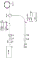
Fig. 4 shows a schematic diagram of a system using the detection signals described in relation to fig. 3. This system may be referred to as frequency domain reflectometry. The output of the source 300 is connected to an optical coupler 301, one output from the optical coupler 301 being connected to the measurement fibre and one output being connected to the receiver 42 to provide the reference signal. The coupler 301 may be a 50:50 coupler or may be selected to direct a larger portion of the light to a measurement fiber or receiver to optimize signal-to-noise ratio.
The AOM modulates light using an RF signal to diffract light propagating through a medium, and thus, the frequency of the output light is shifted from the RF frequency. RF frequency (f) of AOMRF) Typically in the range of 200MHz, and Δ f may be selected such that fRF=(△f+fm) Wherein f ismIs the desired heterodyne frequency. Thus, the optical frequency output by source 40 is given by: f. of1-(△f+fm),f2-(△ f+fm)...fn-(△f+fm)。fmTypically a few kHz, for example, less than af. f. ofmCan be chosen to be zero, which gives a homodyne system.
fmCan be selected as<1/(Tr) Thus, a single heterodyne carrier is performed for points along the measuring fiberA wave.
The probe pulses 1010,1020,10nO may be amplified by (AMP)303 and filtered By (BPF) 304 before being launched into the measurement fiber 1 via the optical circulator 2. The back-scattered light is coupled through the circulator 2, optionally through an amplifier 305 and a filter 306 to an optical coupler 307. In coupler 307, the backscattered light is mixed with unmodulated light from source 300 and directed to receiver 42.
At the receiver, at f (transmitted via couplers 301, 307)1,f2,..fnDown backscatter pulse with at f from source1-(△f+fm),f2-(△f+fm)... fn-(△f+fm) The following CW optical signals are mixed as schematically shown in fig. 5. Each returned frequency is adjacent to its own frequency f from the generated heterodynemThe phase change of the backscattered light modulates the phase, which is caused by the change of the scatterers causing the backscattering.
Taking into account the delay t with respect to the transmitted pulse returned to the interrogator1Corresponding to the gauge length in the test fiber. As shown in fig. 6, each transmitted pulse samples a snapshot of the backscatter from the meter. As shown, the subsequent samples are at the heterodyne frequency fmThe carrier is established because the phase difference between the local source and the returning backscatter is at frequency fmBy 2 π, thus, at frequency fmAnd then cycle through constructive and destructive interference. Testing the time of arrival t in an optical fiber1Adds or subtracts from the total phase difference, which changes the moment when constructive or destructive interference occurs and, therefore, results in phase modulation in the carrier wave. In this way, the heterodyne carrier is offset with respect to fm(φ(t1) The phase of the test fiber is reached corresponding to time t1Of the integrated stress variation along the distance of the fiber. To calculate the phase change over the gauge length (i.e., the length of fiber traveling during time Δ t), φ (t) is calculated1)-φ(t1-△t)。
As described above, the backscattered light from multiple scatterers add coherently and can therefore sum destructively, so that there is no return signal that can be measured. As explained in detail below, the use of a large number of probe pulses at discrete frequencies can reduce the probability of destructive addition occurring.
Coherent fading occurs when the scattering from multiple scatterers adds up such that no or little backscatter signal is generated on the optical detector. When no backscatter is received from a portion of the fiber, no measurement can be made or the SNR is reduced. This effect is clearly undesirable.
Fig. 7 shows a portion of a measurement fiber in which probe light 70 travels from left to right and backscatter 71 returns from right to left. The probe pulse having a duration TpWhich is typically on the order of 10-100 ns. May be in the period TdThe backscatter is sampled. Scatterers 72 are randomly distributed throughout the fiber, wherein the average delay between scatterers is significantly less than Td. Each location (site) provides a reflection, each of which adds together coherently. Each sample represents a window period TdDuration is defined by length TpIs used to illuminate the surface of the substrate. In this way, corresponding to Tp+TdAt T, the pair of scatterers within the length of the optical fiberdDuring which the total optical power sampled contributes. However, at the beginning and end of the pulse corresponds to a duration TdThe/2 scatterers are not illuminated for the entire observation time and can therefore be ignored.
FIG. 8 schematically shows the optical phase of a reference relative to the optical frequency q from a scattering location p For the purposes of this discussion, it is assumed that all scatterers carry the same power return. Fig. 8 shows two
 frequencies 1,2 and six scatterers 1-6. As can be seen in fig. 8, the phase of each frequency from a particular scatterer is different, as expected, the difference increases with time (distance along the fiber). The time delay of each reflection relative to the reference is dpSo that:

due to the laser being at TpIs coherent, so the number of 2 pi in each scattering phase delay can be neglected, so that Thus, in order for one detection frequency to fade completely (i.e. no return signal), for each scatterer p, there must be another scatterer j with opposite phase, so that
 Or
Or

Δ f can be selected such that f1And f2The phase difference between the lights is at TdInternal variation less than 2. pi (i.e., Δ f)<(1/Td)). Then, from f2And f1 will be less likely to disappear altogether at the same time. To which Is small enough to make
 Scatterers of (a) cannot exist j so that
 That is to say that the first and second electrodes,

to which Large enough to surroundOscillate so that
 The situation is more complicated with scatterers of (2). It can be shown that a set of scatterers that achieve coherent fading at two frequencies is small.
If it is assumed that the scatterer is over the entire TpInner lighting segment TdThe inner plane is uniformly distributed, then in f1And f2The phase difference between the back-scattered light at time TdIs pi (i.e., Δ f ═ 1/(2. T)d) In the case of f)1When the backscatter is mostly fading, the backscatter will typically be at f2It is strong. In this way, from TdThe pairs of early and late scatterers are superimposed at f1Does not generate light, is superposed at f2Generates strong light. In this way, the use of two coherent frequency systems with appropriate difference frequencies can be significantly immune to coherent fading.
In a typical system, where TdIn the range of 4ns, the optimum Δ f is 1/(2. T)d) A range of 125MHz (100 and 600MHz may be suitable for some examples). In some cases, TdMay be significantly longer to improve SNR at the receiver. This can result in a lower optimal af value that falls within the desired detection band, which makes it impossible to distinguish between adjacent disturbances on the fiber. In this case, Δ f ═ 2v +1)/(2.T can be usedd) Where v is an arbitrary integer, this is most likely at f1Providing information from f in case of fading2Strong backscattering, allowing measurements to be made.
In fact, TdThe sampling window above may not be rectangular, and thus may need to be paired with af and TdSome tuning is done to minimize fading.
The same principle can be used in reverse to do this by setting Δ f-v/Td(where v is any non-zero integer, for example)) to create a composite pulse that is more susceptible to intra-pulse coherent fading than a single frequency pulse. This can be used to create a distributed sensor in which changes in fibre stress are deliberately induced from each point on the fibreThe variation of the directly decoded backscatter amplitude is shown in fig. 33. In contrast to other systems disclosed herein, the return backscattered pulses are detected directly 309 (after optional filtering and amplification at 305, 306).
Thus, the amplitude variation of the return pulse can be determined but the phase information cannot be extracted. In the absence of phase information, the non-linear relationship between stress and amplitude cannot be decoded, and therefore, a quantitative measurement of stress variation cannot be made. However, the system provides an indication that the stress has changed at a particular location (the location being determined from the round trip time). Information that some form of change has occurred may be useful in certain applications, particularly in combination with measurements over time indicating the frequency of the change.
Returning to the minimum-fading embodiment, for ideal erasure, the same power from each reflection must be captured by the fiber. Ideal coherent fading has a small probability, but can occur. However, since any amount of fading reduces the signal level and hence the signal-to-noise ratio, perfect fading is not required to reduce performance.
In the above example, two frequencies have been considered, but the probability of a full fade can be further reduced by increasing the number of optical frequencies.
At the receiver, only light of the same polarization interferes to add coherently and give the desired signal. Therefore, polarization alignment is required between the backscattered signal and the reference signal from the source. Birefringence in the fiber and the assembly can cause polarization changes in the propagating light. Although the polarization can be adjusted to account for slow changes affecting the overall backscatter, the polarization can also change faster than it can accommodate (e.g., within each backscatter trace), resulting in polarization fading of the received signal. Temperature and stress can cause changes in birefringence, which leads to undesirable cross-sensitivity of the measurement SNR to temperature, vibration, and even stress changes intended to be measured.
Fig. 9 shows a schematic diagram of a system using the same principles described above, but including means for mitigating polarization fading. The source 300 generates an array of frequencies spaced at af, as described above, but in this example adjacent frequencies have different (but not orthogonal) polarizations. Components shown in fig. 9 having the same reference numerals as in fig. 4 provide equivalent functions. If the birefringence does not generate circular polarization, the adjacent frequencies may be orthogonal.
At receiver 91, light from source 300 is split by coupler 310 into couplers 311, 314. The output of each coupler 311,314 is connected to a detector 313,316. The backscattered signal from the measurement fibre is split by the coupler 318 to the coupler 311,314. One of the paths includes a polarization controller 317, which rotates the polarization of the backscattered light by 90 °. The example polarization controller 317 may also be positioned in any of the other three paths.
Since the adjacent frequency components (which interfere at the receiver, as described above) are not orthogonally polarized in the absence of birefringence, interference will occur at 313 and 316. As long as the source generator produces light with components of each polarization (including circularly polarized components), interference will always occur at either 313 or 316 or at 313 and 316, regardless of the birefringence of the assembly and test fiber, and measurements can always be made. The source generator transmits linear and circular polarizations. It is possible that the birefringence will constitute a quarter-wave plate to convert linear polarization to circular polarization at some point along the length of the fiber. This prevents interference (due to impinging linear polarization into circular polarization) if only linear polarization is emitted. Both linearly polarized and circularly polarized transmission avoid this limitation.
As described above, the system described with reference to fig. 4 operates as a frequency domain reflectometer that compares backscattered light with a reference directly from the source. Such systems are simple and have high spatial resolution, but also have disadvantages. Such systems rely on a stable source frequency and variations in this frequency with backscatter period are indistinguishable from the stress variations being measured. In addition, a measurement for each gauge length is determined from the difference between the integrated stress to the beginning of the particular gauge length and the integrated stress to the end of the particular gauge length along the entire length of the optical fiber. Any measurement error, for example due to a phase change at any point along the fibre that exceeds the maximum instantaneous frequency that can be demodulated, results in an erroneous measurement. That is, excessive variation at any point along the fiber results in errors at all larger distances.
Fig. 10 shows a diagram of a time domain system that utilizes similar principles as the system of fig. 4, but which can overcome several of the difficulties described above for frequency domain systems. Specifically, the change in stress between two points that become the boundary of the gauge length is calculated independently of the change in stress in other locations along the measurement fiber.
The reference coil 209 of the fiber may be temperature and vibration controlled to provide a zero signal reference.
Fig. 11 illustrates an example receiver module for use as the receiver 208 in the system of fig. 10. The incident backscatter at the input 110 is divided three ways by the optical coupler 111. The first optical path is delayed in the delay element 213 by a time Ti. The second optical path includes a down shifter 211(down shifter), and the down shifter 211 shifts the optical frequency down (Δ f + f)m) And an upward shifter 212(upshifter) in the third optical path shifts the frequency (Δ f + f) upwardm). The down shifter 211 and the up shifter 212 may be AOMs operating in CW mode to provide frequency modulation, but not amplitude modulation.
The downwardly shifted and delayed signals are combined in optical coupler 115 and received by detector 214. Similarly, the upwardly shifted and delayed signals are combined in optical coupler 117 and received by detector 215.
At detector 214, fk+1Delayed backscattered light of (a) and (f)kIs interfered with by undelayed (but shifted down at the optical frequency) backscattered light to produce fmThe heterodyne carrier wave of (1). Each pair of frequencies is combined in this manner to form a carrier. Similarly, at detector 215, fk-1Delayed backscattered light of (a) and (f)kIs not delayed (but is shifted up at the optical frequency) backscatter interferes to also produce fmThe heterodyne carrier wave of (1). The generated combination is shown in the lower half of fig. 11.
Optional polarization controllers 209,210 may be included to account for birefringence within the receiver optical assembly. The down shifter 211 or the up shifter 212 may be configured to give a phase difference of the signals such that there is any phase difference between the signals from the detectors 214,215, which may provide an advantage to the decoding process.
The receiver system of fig. 11 can be isolated from vibration and temperature stabilized to avoid variations in relative path lengths that could lead to measurement errors.
Fig. 12 shows an alternative receiver structure to that of fig. 11, in which the delay is applied to the up-shifted and down-shifted paths, but not to the unshifted paths. The operation of the receiver of fig. 13 is as described in relation to fig. 11.
As explained earlier, it is possible to set Δ f and observe time TdMinimizing intra-pulse fading makes it unlikely that both adjacent frequencies will fade. In this way, if a 1011+1022 fade occurs on detector 214 because either 1011 or 1022 have been superimposed to zero, then 1021 and 1012, both on detector 215, are less likely to fade. Therefore, the signal should always be present on either detector 211 or detector 213.
However, because the delayed and undelayed backscatter has been combined in the time domain embodiment, intra-pulse coherent fading must also be considered (fig. 16). Because the time domain reflectometer superimposes the backscattered light with delayed backscatter from further along the test fiber, components from delayed and undelayed backscatter destructively interfere, generating no light. Can be obtained by optimizing the difference frequency deltaf and the delay time TITo minimize this possibilityAnd (4) sex. Consider the combination 1011+1022 at detector 214. If the combination produces destructive interference, the backscatter from 1011 must add destructively with the delayed backscatter from 1022, which has a pass frequency f2Light passing through TIThe delay experienced is obtained. For the equivalent combination 1012+1021 on detector 215, the frequency is f1Is subject to a delay of TI. If the frequency difference Δ f is set such that Δ f is 1/(2. T)I) Then the combination 1012+1021 at detector 215 must be added constructively. In this way coherent fading within the pulse can be minimized. As described above, a case may be required where Δ f ═ 1+2w)/(2.TI) Where w is an integer.
When generating hundreds of frequency tones (tones), it is advisable to detune slightly from this setting, so that f1,f3,f5Etc. may not all fade at once.
Fig. 13 shows a demodulation algorithm for measurements using signals from the detectors shown in the receivers of fig. 11 and 12. The example algorithm is based on arranging a phase difference of 180 degrees between the carriers observed on detectors 116 and 118 so that the maximum carrier signal is obtained when the signals from the two detectors 214 and 215 are subtracted. This has the following advantages: reducing the effects of common mode noise (e.g., frequency noise in the up-shifter/down-shifter drive electronics). The signal subtracted from 502 is split and enters 1 or more sample pick-up modules (508,510,513,516). These modules test the fiber from a region of interest (to delay t with respect to the probe pulse)xArriving at the detector) extracts the backscatter at the corresponding time instant and discards the other regions. The sample picking module may also perform averaging or filtering as needed. Relative to fmThe phase of the signal present at the sample pick-up block for the lower carrier reference is calculated by blocks 509,511, 514 and 517.
An example orthonormal phase demodulation module using arctangent (arctan) is shown in fig. 14. The demodulated phase represents the point on the test fiber at time TdThe phase of the phase change. With a delay of t0The returned backscatter corresponds to a non-sensitive referenceThe fiber, and therefore, the laser noise can be reduced by taking the signal off of the demodulated signal, which is demodulated from other points on the fiber, to obtain the final phase signals 512,515 and 518. Obviously, in this way, by adding more sample pick-up modules and phase demodulation modules, up to a maximum of T can be demodulatedr/TIAny number of points of interest q.
Over time, the phase delays and birefringence of the fibers, components and sources within the interrogator will drift slowly, thus necessitating small adjustments to the system operating parameters for continued optimal operation. Phase difference applied by up-shifter and down-shifter modules in a receiver Will be trimmed to maintain the inverse f on
 detectors 214 and 215mAnd (4) carrying waves. This is achieved by minimizing the common mode carrier received from the reference coil. The summing unit 503 sums the light from the detectors 214 and 215. The sample picker 504 extracts the backscatter related to the reference coil. Carrier frequency f is extracted by module 505mThe power level of (c).
As previously mentioned, only the superposition of light components with similar polarizations generates interference. Therefore, there is a possibility that: the birefringence in the optical test fiber 1 and the interconnected components can act together (conspire) such that no interfering light is generated on the detectors 214 and 215. This can be overcome by: polarization controllers 209 and 210 are provided to compensate for residual birefringence in the receiver interferometer. The source generator can then be set such that adjacent light component frequencies have a relative polarization of 45 degrees, with the initial polarization set such that the light component with each polarization state is emitted in the composite pulse. As shown in fig. 17, for one frequency component pair, interference is observed on at least one detector regardless of the birefringence of the test fiber.
Fig. 15 illustrates an example carrier size measurement module. The strength of the received carrier wave is low pass filtered at 506. Feedback module 507 adjusts the phase applied by the up shifter and the down shifterDifference (D) So that a minimum signal is output from
 block 506, thus ensuring that carrier inversion occurs at both detectors.
Fig. 34 shows an alternative demodulation algorithm that combines the signals from the detectors, respectively. The backscatter from each detector corresponding to each point on the test fibre is determined separately, resulting in two streams of picked up samples for each point of interest on the test fibre. The strength of the carrier wave within each picked sample stream is then determined. The combining step selects or combines backscatter from the two (or more) resulting streams of picked carrier samples to provide a single phase decoded carrier. For example, the combining step may select a picked sample stream that coincides with the largest carrier size. The single combined phase-decoded carrier is then demodulated to represent the stress variations at a particular point on the test fiber.
In summary, these arrangements have many advantages:
1. many combinations of component frequencies are for carrier fmIt is helpful. This improves sensitivity for the following reasons:
i. the power that can be emitted at a single frequency is generally limited by stimulated brillouin scattering and other nonlinear effects. Because the composite pulse includes many different frequencies, the total power that can be transmitted by the system described herein far exceeds the power that can be transmitted by a single frequency system. This results in higher backscatter power and better SNR.
Because a larger proportion of the optical detection zone is occupied by the desired signal, the detection SNR is improved compared to a single frequency system.
Differential detection removes the effects of common mode signals on the detector, such as frequency shifter noise, electrical interference and some optical noise.
2. As described above, by setting Δ f to an appropriate value, the probability of backscatter from adjacent frequencies that are all fading can be made very small. Because different backscatter pairs form carriers on each detector 214 and 215, it is virtually impossible for the light from both detectors to be able to fade.
3. By emitting adjacent frequencies with relative polarization states at or near 45 degrees, the light from 214 and 215 must contain interference, regardless of the delay time TIBirefringence in the source fiber during. If the birefringence causes light from (say))1011 to be orthogonal to 1022, so that no interference light from this combination is produced at detector 214, this same rotation must cause 1021+1012 to generate interference light at 215. (the birefringence experienced by light at a frequency difference of about Δ f will be very similar)
4. Frequency shifters 211 and 212 can apply a phase difference such that the carriers f received at 214 and 215mCan have an arbitrary phase difference. A feedback system may be required to compensate for the changing receiver optics and to maintain the desired phase difference across detectors 214 and 215. This phase difference can be used in two ways:
i. in the case where minimal sensitivity to fading and minimal noise are required, a phase difference of 180 degrees will allow a strong carrier to be formed when 214 is reduced from 215, thus reducing noise as detailed above
in case the highest dynamic range is required, a phase difference of 90 degrees will allow decoding the stress variation within each part of the fiber without the need to refer to the previous sample by quadrature detection.
Alternatively, the undelayed light can be superimposed with the delayed and downwardly shifted light or the delayed and upwardly shifted light as shown in fig. 12.
Fig. 18 illustrates an example physical implementation of a time domain receiver as functionally described above with respect to fig. 11 and 12.
The received backscattered light is separated by a coupler 210, where each output directs the light in an opposite direction through the system. Couplers 211,221 separate the respective light, wherein the first portion follows bypass path 180, which bypass path 180 may include a selectable attenuator 212 to adjust the power level. The other output of the couplers 211,221 couples light to another pair of couplers 214,219, the splitting of which pair 214,219 between two directional paths. Optical isolator217,218 confine the light to propagate in the desired direction on each path. The isolators may be arranged with the other components in any suitable order on each path. For example, it may be preferable to position each isolator at the input end of each path to avoid reflections from the frequency shifters 215,216 or polarization controllers 226, 227. The frequency shifter 215 (e.g., AOM) shifts the optical frequency of the signal up by Δ f + fmAnd a frequency shifter 216 (e.g., AOM) shifts the optical frequency down by Δ f + fm。
The upwardly shifted and downwardly shifted light propagates through the couplers 211,214, 219,221 in opposite directions and is received at the receivers 223,225, where the light is mixed in dry with the light transmitted through the bypass path 180.
Figure 19 shows a further physical implementation of a time domain receiver. The received backscattered light is split into three components by the 3x3 coupler 231. One component is directed through a filter with a delay (T)IDelay coil 232 of/2) and directed onto a faraday mirror 233. The light returning to the coupler 231 is thus delayed by TI. The faraday mirror mitigates any birefringence effects in the delay coil 232.
The other two outputs from coupler 231 are directed to an up shifter 238 and a down shifter 234, respectively, each of which may be an AOM as described above. The upwardly and downwardly shifted light combines with the delayed light in couplers 235,240 and is directed to receiver 237,242 for detection. An optional polarization controller 239,241 may be included to ensure that the polarization of the delayed and offset signals are aligned at detector 237,242. Thus, the receiver of fig. 19 generates the required signal combination at the detector.
Fig. 20 shows a further physical implementation of a time domain receiver. The received backscattered light is separated by a coupler 250. One output of coupler 250 is coupled to coupler 251, coupler 251 splitting the light into delay path 254 and a downward offset path. The other output of coupler 250 is coupled to coupler 257, coupler 257 splitting the light into delay path 254 and an upward-offset path.
The downward offset path includes an AOM 252 and a faraday mirror 253. Light passes downwardsThe offset path, in two passes through down shifter 252, the optical frequency is shifted down and returned to coupler 251. AOM 252 at (. DELTA.f + f)m) Operation at RF frequency of/2, which provides the total (. DELTA.f + f)m) The frequency shift of (2). The downwardly shifted light is mixed with the delayed light in coupler 251 and passes through detector 261, where it is coherently mixed and detected. Similarly, the light is shifted up by AOM 256 and mixed with the delayed light at receiver 259 to generate the desired component. An optional polarization controller 262 may be included to remove birefringence in the receiver system.
Fig. 21 shows a further example of a receiver that utilizes only one frequency shifter. The received backscattered light is coupled to a coupler 270, and one output of the coupler 270 is connected to a first bypass path 282. The other output of coupler 270 is connected to AOM 271, AOM 271 shifting the frequency by Δ f + fm(offset up or offset down). Another coupler 272 directs the offset light to a faraday mirror 273, which passes through AOM 271 and returns the light to the second bypass path 283 via coupler 270. The other output of coupler 272 passes through delay element 274 and then couples light to detector 279,281 via coupler 275,276,277. At detector 279, the delayed shifted light is mixed with the unshifted undelayed light that passes through bypass path 282. At detector 281, the delayed twice shifted light is mixed with the once shifted light. Thus, at both detectors there is a mixture between them with a component of Δ f. The selectable polarization controllers 283 and 282 are arranged to compensate for birefringence in the optical system. Fig. 22 shows a frequency source generator illustrating two components. Light from low frequency noise laser 101 is split into two components by coupler 111. One path is frequency shifted by Δ f by AOM 112. The remaining light from 111 passes through a selectable attenuator 115 to balance the component amplitudes and through a selectable polarization controller 116, which polarization controller 116 can be used to set the difference between the polarizations of the two frequency source components. The two paths are recombined by coupler 117, passed through optional isolator 118, and then to the output.
Fig. 23 shows an alternative source generator that produces three frequency components. Light from the laser source 131 is split by the 3x3 coupler 132. A portion of the output light is reflected through FRM 133 without being shifted. The remaining portion is directed through an upward offset AOM 137 and through a polarization shifter 138 and reflected back to coupler 132 by FRM 139. In this way, three light components appear at the output. By detecting the component at Δ f, the light at the detector 133 can be used to balance the power from the three components. Polarization rotators 138 and 135 can be used to set the relative polarization of the three components.
Fig. 24 shows a second example configuration for generating three component frequencies. Here, light from the low frequency noise laser source 141 is split by the coupler 142. A portion of the light is further split by coupler 143. The undeflected portion of the light continues through couplers 146 and 149 through optional isolator 152 to the output. Another portion of the light is shifted by AOM 144, whose polarization is adjusted by controller 145 and then recombined to reach the output. The other path passes through coupler 142 and AOM 147 (which are selected to shift the light from AOM 144 in the opposite sense) and polarization controller 148 to appear at the output. The polarization controller can be used to generate any desired relative polarization between the components. The af component at 150 and 151 can be monitored to balance the magnitude of the output at three frequencies.
Fig. 25 shows another option for generating three frequency components. Light from laser 161 is split by coupler 162. A portion of the outgoing undeflected light is reflected 170 back through coupler 162 to the output via optional isolator 171. 170 may be faraday rotator mirrors to remove birefringence effects in the optical assembly. The remaining light from 162 is directed to coupler 163 where it is further split. A portion of the light is shifted up 164 and the remaining portion is shifted down 167 and reflected back to the output by 166 and 169, which may be FRMs. Selectable polarization shifters 165 and 168, which may be faraday rotators, allow the components to have the desired relative polarization.
Fig. 26 illustrates an example configuration for generating multiple frequencies based on a cyclic loop. Light from the low frequency noise laser 101 is coupled into the loop by a coupler 102. A portion of the light continues through AOM 103, being offset Δ f at AOM 103. The amplifier 104 compensates for the loop loss and the filter 105 limits the number of frequencies generated and improves the SNR. Coupler 106 separates some of the light from the loop towards the output via optional isolator 110. The remaining light is coupled by selectable isolator 107, through selectable polarization rotator 108 (which may be a 45 degree faraday rotator), through selectable attenuator 109, and back into the loop via coupler 102. The attenuator 109 can be used to tune the loop and balance the power of all the multiple components. The filter 105 can be arranged to limit the number of frequencies generated and provide pre-emphasis to balance CNR for each frequency.
Fig. 27 shows an alternative version in which light from a source 181 is split by a coupler 182 and then travels through an AOM 183, through a polarization controller 184, a polarization rotation stage 185, a bandpass filter 186, through a coupler 187 and through an optional isolator 190 to the output. The amplifier 188 recycles the light such that a plurality of light components are generated at the output. The filter 186 can be used to balance the SNR of the components and limit the number of components generated.
Fig. 28 shows an alternative arrangement for generating multiple frequencies. Two or three frequency sources 142 are amplified 143. The highly nonlinear fiber (e.g., photonic crystal fiber) 144 plus amplifier fiber generates additional frequency components by four-wave mixing. The BPF 145 limits the components to the required number and wavelength range.
Fig. 29 shows an alternative configuration. Here, the comb generator output is band pass filtered to the range of interest. Note that for some comb generator types, the number of frequencies generated will be represented by TIΔ f, therefore, longer T may be requiredITo ensure that sufficient components are transmitted.
In the above description, a plurality of sounding signals at a defined frequency have been transmitted. A series of aligned pulses at each frequency are sent to the measurement fiber. To improve the sensitivity and dynamic range of the system, a second set of probe signals may be transmitted, as shown in fig. 30. The second set of signals has the same characteristics as described above but at a second wavelength, which is separate from the wavelength at which the first signal is located. That is, there are multiple optical signals at λ 0 and multiple optical signals at λ 1, where there is no overlap in the frequency/wavelength domain between the signals at λ 0 and λ 1. The signals at λ 0 and λ 1 are both a series of pulses in the time domain as described above, but with a time offset between the series of pulses, as seen in fig. 30.
At the receiver, the two wavelengths are separated and detected independently. The above receiver architecture can be used for two wavelengths, where each wavelength is directed to a detector of a particular wavelength. For example, a wavelength selective demultiplexer is utilized immediately before the plurality of detectors.
The system increases the dynamic range of the system because the sampling rate is doubled, allowing a higher maximum instantaneous rate of phase change. Sensitivity is also increased as the sampling rate is doubled.
More than two sets of signals may also be used to further improve performance.
The signal may be obtained by splitting the light from one wide bandwidth source generator or by having two separate source generators derived from two lasers.
The delay length in the time domain receiver sets the gauge length over which the phase change in the test fiber is calculated. Different gauge lengths may be desired for various applications. This can be accommodated by splitting the backscattered light into two or more receivers, each with a different time, as shown in fig. 31. The arrangement of figure 31 enables different gauge lengths to be measured simultaneously. Furthermore, the variable delay element may be used in any receiver to provide a variable gauge length.
The frequency shift in the receiver system sets the combination of the backscatter impinging on the detector to generate the carrier wave. By introducing a second set of receivers with different offsets up and down, as shown in fig. 32, different frequency combinations can be directed to the detector. Each receiver uses a signal equal to nmSuch that different combinations of carriers are mixed to produce fmThe lower identical heterodyne carrier.
This may have the advantage: significant birefringence or fading is observed because the probability of signal fading is reduced over that of both 611 and 612 over all detectors 610 and 613.
The above invention has been given primarily with reference only to distributed sensors. However, these techniques and apparatus may also be applied to systems having reflectors to produce specific return signals at defined locations along the fiber. It may be desirable to increase the sensitivity of the measurement fibre at a defined location along the measurement fibre. In addition, the system may provide sufficient sensitivity to detect events using an appropriate transducer. For example, the length of fiber may be wrapped around a transducer that converts acceleration into fiber stress. The systems described herein may be capable of sensing changes in a relatively short length of optical fiber associated with a transducer to detect acceleration. In this case, the system has the following advantages: the backscattered light from the modulated fiber length can be used to make measurements, rather than requiring a particularly insensitive fiber near the transducer. This is because the system is insensitive to fading caused by stress variations in the transducer fiber.
Any of the optical couplers described herein may be the same coupler or may be configured with different coupling ratios for each output. The desired ratio is selected to optimize system performance.
Although the present invention has been described in connection with some embodiments, it is not intended to be limited to the specific form set forth herein. The scope of the invention is, however, limited only by the appended claims. Furthermore, although a feature may appear to be described in connection with particular embodiments, one skilled in the art would recognize that various features of the described embodiments may be combined in accordance with the invention. In the claims, the term "comprising" does not exclude the presence of other elements or steps.
Furthermore, the order of features in the claims does not imply any specific order in which the features must be performed and in particular the order of individual steps in a method claim does not imply that the steps must be performed in this order. However, the steps may be performed in any suitable order. Furthermore, singular references do not exclude a plurality. Thus, reference to "a" or "an", "first", "second", etc., does not preclude a plurality. In the claims, the term "comprising" does not exclude the presence of other elements.
Claims (13)
1. An optical sensing system, comprising:
a source generator configured to generate
A set of n time-aligned optical probe pulses, each pulse at a pulse from f1,f2,...fnDifferent optical frequencies are selected, where n is the number of pulses and n is equal to 2 or greater, each optical frequency is spaced apart from its neighboring optical frequencies by Δ f,
the source generator is configured to send the optical probe pulse to an optical sensing fiber, wherein the optical probe pulse is backscattered by the optical sensing fiber, at least a portion of the backscattered light is captured by the optical sensing fiber in a direction opposite to the propagation of the optical probe pulse,
an optical receiver system configured to receive the backscattered light from the optical sensing fiber, wherein the optical receiver system is configured to mix a delayed version of the backscattered light with at least one frequency-shifted version of the backscattered light, wherein the frequency shift- (. DELTA.f + f) of the at least one frequency-shifted version of the backscattered lightm) Wherein f ismIs a predetermined frequency, and fmLess than af.
2. The optical sensing system of claim 1, wherein the optical sensing fiber comprises at least one sensing region adapted to increase the sensitivity of the system to changes occurring in the at least one sensing region.
3. The optical sensing system of claim 1, wherein the detected amplitude is decoded to provide an indication of a change in stress along the optical sensing fiber.
4. The optical sensing system of claim 1, wherein Δ f ═ v/TdWherein, TdIs the optical observation time and v is any non-zero integer.
5. The optical sensing system of claim 1, wherein Δ f ═ 1+2w)/(2x TI) Or (1+2v)/(2x T)d) Wherein w and v are any integer, TdIs the optical signal observation time and TIIs the backscatter delay time.
6. The optical sensing system according to any of claims 1 to 5, wherein Δ f is 100-600 MHz.
7. The optical sensing system of claim 1, wherein n ≧ 50.
8. A method of detecting stress in an optical sensing fiber, the method comprising the steps of:
generating a set of n time-aligned optical probe pulses, each pulse at a pulse from f1,f2,...fnSelecting different optical frequencies, wherein n is the number of pulses and n is more than or equal to 2, each optical frequency is separated from the adjacent optical frequency by deltaf,
sending the optical probe pulse to the optical sensing fiber, wherein the optical probe pulse is backscattered by the optical sensing fiber, at least a portion of the backscattered light is captured by the optical sensing fiber in a direction opposite to the propagation of the optical probe pulse,
receiving backscattered light from the optical sensing fiber,
an optical receiver system configured to receive the backscattered light from the optical sensing fiber, wherein the optical receiver system is configured to mix a delayed version of the backscattered light with at least one frequency-shifted version of the backscattered light, wherein the frequency shift- (. DELTA.f + f) of the at least one frequency-shifted version of the backscattered lightm) Wherein f ismIs a predetermined frequency, and fmLess than Δf, and
determining a phase change at a location along the optical sensing fiber based on the detected change in amplitude and the time of the sample showing the amplitude change.
9. The method of claim 8, wherein Δ f ═ (1+2v)/TdOr Δ f ═ 1+2 w/TIWherein, TdIs the optical observation time, TIIs the backscatter delay time and v and w are integers.
10. The method of claim 8, wherein the set of n time-aligned optical detection pulses is generated by modulating a set of source optical signals, each source optical signal being at a slave f1,f2...fnDifferent optical frequencies are selected.
11. The method of any one of claims 8 to 10, wherein the polarization of each optical probe pulse is different from the polarization of optical probe pulses at adjacent optical frequencies.
12. The method of claim 11, wherein the polarizations of adjacent optical probe pulses are not orthogonal.
13. The method according to any one of claims 8 to 10, wherein Δ f is between 100MHz-600 MHz.
Applications Claiming Priority (3)
| Application Number | Priority Date | Filing Date | Title |
|---|---|---|---|
| GB1700994.5 | 2017-01-20 | ||
| GB1700994.5A GB2558922A (en) | 2017-01-20 | 2017-01-20 | Distributed acoustic sensing |
| PCT/EP2018/050793 WO2018134137A1 (en) | 2017-01-20 | 2018-01-12 | Distributed acoustic sensing |
Publications (2)
| Publication Number | Publication Date |
|---|---|
| CN110383009A CN110383009A (en) | 2019-10-25 |
| CN110383009B true CN110383009B (en) | 2021-09-07 |
Family
ID=58463029
Family Applications (1)
| Application Number | Title | Priority Date | Filing Date |
|---|---|---|---|
| CN201880015050.3A Active CN110383009B (en) | 2017-01-20 | 2018-01-12 | Optical sensing system and method for detecting stress in optical sensing optical fiber |
Country Status (7)
| Country | Link |
|---|---|
| US (1) | US10935398B2 (en) |
| EP (1) | EP3571475B1 (en) |
| JP (1) | JP6921236B2 (en) |
| CN (1) | CN110383009B (en) |
| ES (1) | ES2879252T3 (en) |
| GB (1) | GB2558922A (en) |
| WO (1) | WO2018134137A1 (en) |
Families Citing this family (17)
| Publication number | Priority date | Publication date | Assignee | Title |
|---|---|---|---|---|
| US10330526B1 (en) * | 2017-12-06 | 2019-06-25 | Saudi Arabian Oil Company | Determining structural tomographic properties of a geologic formation |
| CN109941308B (en) * | 2019-03-21 | 2020-07-07 | 北京交通大学 | Abnormal disturbance signal analysis method based on optical fiber M-Z interference |
| JP7111045B2 (en) * | 2019-04-03 | 2022-08-02 | 日本電信電話株式会社 | PHASE MEASUREMENT METHOD AND SIGNAL PROCESSING DEVICE |
| JP7240947B2 (en) * | 2019-05-09 | 2023-03-16 | 株式会社アドバンテスト | Optical test equipment |
| GB2588177B (en) * | 2019-10-11 | 2022-10-12 | Sintela Ltd | Signal processing methods for an optical detection system |
| JP7298471B2 (en) | 2019-12-25 | 2023-06-27 | 沖電気工業株式会社 | Optical coherent sensor and optical coherent sensing method |
| CN111157102B (en) * | 2020-01-02 | 2022-03-08 | 河海大学常州校区 | Positioning method for eliminating frequency interference in distributed optical fiber sensing system |
| US11543287B2 (en) * | 2020-05-20 | 2023-01-03 | Nec Corporation | Distributed acoustic sensing using multi-band time-gated digital orthogonal frequency domain reflectometry |
| CN111928938A (en) * | 2020-09-10 | 2020-11-13 | 无锡科晟光子科技有限公司 | Long-distance distributed optical fiber vibration detection system |
| WO2022054254A1 (en) * | 2020-09-11 | 2022-03-17 | 日本電信電話株式会社 | Vibration detection apparatus and vibration detection method |
| GB2603205A (en) | 2021-02-02 | 2022-08-03 | Focus Sensors Ltd | Ground sensing utlising active sources |
| GB2609641A (en) * | 2021-08-11 | 2023-02-15 | Sintela Ltd | Signal processing methods for an optical detection system |
| CN113790792A (en) * | 2021-08-18 | 2021-12-14 | 北京航空航天大学 | Distributed optical fiber acoustic wave sensing device based on homodyne detection and demodulation method |
| AU2022331739A1 (en) * | 2021-08-18 | 2024-03-14 | Prisma Photonics Ltd | Real-time quasi-coherent detection and fiber sensing using multi-frequency signals |
| US11942986B2 (en) * | 2021-09-24 | 2024-03-26 | Viavi Solutions Inc. | Optical time-domain reflectometer (OTDR) including channel checker |
| GB2616282A (en) * | 2022-03-02 | 2023-09-06 | Sintela Ltd | Signal processing methods for an optical detection system |
| CN116182916B (en) * | 2023-04-27 | 2023-07-07 | 四川省医学科学院·四川省人民医院 | Photon sensing system for broadband phase modulation processing |
Family Cites Families (23)
| Publication number | Priority date | Publication date | Assignee | Title |
|---|---|---|---|---|
| US4363114A (en) * | 1981-01-21 | 1982-12-07 | The United States Of America As Represented By The Secretary Of The Navy | Low noise remote optical fiber sound detector |
| GB2189880B (en) * | 1986-04-30 | 1989-12-28 | Plessey Co Plc | Optical sensor system |
| JPH02242237A (en) * | 1989-03-15 | 1990-09-26 | Matsushita Electric Ind Co Ltd | Acoustooptical light frequency shifter |
| JP2750781B2 (en) * | 1990-11-13 | 1998-05-13 | 本田技研工業 株式会社 | FM radar |
| GB9324333D0 (en) * | 1993-11-26 | 1994-01-12 | Sensor Dynamics Ltd | Measurement of one or more physical parameters |
| JP3583906B2 (en) * | 1996-07-15 | 2004-11-04 | 伊藤 弘昌 | Optical rangefinder |
| GB0409865D0 (en) * | 2004-05-01 | 2004-06-09 | Sensornet Ltd | Direct measurement of brillouin frequency in distributed optical sensing systems |
| GB2442745B (en) * | 2006-10-13 | 2011-04-06 | At & T Corp | Method and apparatus for acoustic sensing using multiple optical pulses |
| US20080266570A1 (en) * | 2007-04-26 | 2008-10-30 | Sezerman Omur M | Detection and location of breaks in distributed brillouin fiber sensors |
| CN101141200B (en) * | 2007-10-15 | 2010-08-04 | 哈尔滨工业大学 | Multi-frequency phase modulation based multi-wavelength source generating apparatus |
| CN101321019B (en) * | 2008-07-03 | 2011-07-20 | 上海交通大学 | Multi-wavelength light source apparatus and method for generating accurate wavelength interval and high flatness |
| JP5421013B2 (en) * | 2009-07-28 | 2014-02-19 | 株式会社 光コム | Positioning device and positioning method |
| CN101793570B (en) * | 2009-10-21 | 2012-08-08 | 南京大学 | Sensing method of optical-fiber Bragg grating laser device |
| EP2596387B1 (en) * | 2010-09-01 | 2021-10-06 | Services Pétroliers Schlumberger | Distributed fiber optic sensor system with improved linearity |
| US20130113629A1 (en) * | 2011-11-04 | 2013-05-09 | Schlumberger Technology Corporation | Phase sensitive coherent otdr with multi-frequency interrogation |
| CN102571200A (en) * | 2012-01-09 | 2012-07-11 | 南京大学 | Method and device of multi-frequency detecting-light coherent light time-domain reflectometer |
| WO2015180786A1 (en) * | 2014-05-30 | 2015-12-03 | Omnisens Sa | Optical process and optical device, allowing to avoid unwanted nonlinear effects in an optical fiber |
| CN104180833A (en) * | 2014-07-18 | 2014-12-03 | 中国科学院上海光学精密机械研究所 | Optical time domain reflectometer simultaneously sensing temperature and stress |
| JP6535006B2 (en) * | 2014-08-07 | 2019-06-26 | 古河電気工業株式会社 | Optical fiber sensor, seismic survey method, measurement method of oil and natural gas reservoir distribution, strain detection method, and method of locating fracture in formation |
| EP3164742B1 (en) * | 2014-09-12 | 2021-11-03 | Halliburton Energy Services, Inc. | Noise removal for distributed acoustic sensing data |
| US10429234B2 (en) * | 2015-01-21 | 2019-10-01 | Neubrex Co., Ltd. | Distributed fiber optic acoustic detection device |
| JP6308160B2 (en) * | 2015-03-31 | 2018-04-11 | 沖電気工業株式会社 | Optical fiber strain measuring device and optical fiber strain measuring method |
| CN105698871B (en) * | 2016-03-29 | 2018-08-21 | 天津大学 | Distributed strain temperature simultaneously measuring device and method based on probe beam deflation |
-
2017
- 2017-01-20 GB GB1700994.5A patent/GB2558922A/en not_active Withdrawn
-
2018
- 2018-01-12 ES ES18701282T patent/ES2879252T3/en active Active
- 2018-01-12 WO PCT/EP2018/050793 patent/WO2018134137A1/en unknown
- 2018-01-12 CN CN201880015050.3A patent/CN110383009B/en active Active
- 2018-01-12 US US16/479,109 patent/US10935398B2/en active Active
- 2018-01-12 JP JP2019560464A patent/JP6921236B2/en active Active
- 2018-01-12 EP EP18701282.8A patent/EP3571475B1/en active Active
Also Published As
| Publication number | Publication date |
|---|---|
| CN110383009A (en) | 2019-10-25 |
| US20190383648A1 (en) | 2019-12-19 |
| GB2558922A (en) | 2018-07-25 |
| JP2020508467A (en) | 2020-03-19 |
| GB201700994D0 (en) | 2017-03-08 |
| JP6921236B2 (en) | 2021-08-18 |
| EP3571475B1 (en) | 2021-03-31 |
| WO2018134137A1 (en) | 2018-07-26 |
| US10935398B2 (en) | 2021-03-02 |
| ES2879252T3 (en) | 2021-11-22 |
| EP3571475A1 (en) | 2019-11-27 |
Similar Documents
| Publication | Publication Date | Title |
|---|---|---|
| CN110383009B (en) | Optical sensing system and method for detecting stress in optical sensing optical fiber | |
| US11079269B2 (en) | Method and apparatus for optical sensing | |
| AU2017200636B2 (en) | Method and apparatus for optical sensing | |
| AU2015201357B2 (en) | Optical sensor and method of use | |
| US20240012760A1 (en) | Method and Apparatus for Optical Sensing | |
| Gäde et al. | Field evaluation of high resolution optical FMCW monitoring approaches in passive optical networks |
Legal Events
| Date | Code | Title | Description |
|---|---|---|---|
| PB01 | Publication | ||
| PB01 | Publication | ||
| SE01 | Entry into force of request for substantive examination | ||
| SE01 | Entry into force of request for substantive examination | ||
| GR01 | Patent grant | ||
| GR01 | Patent grant |