WO2015085587A1 - 一种基于igbt控制的抽水功率调节系统及方法 - Google Patents
一种基于igbt控制的抽水功率调节系统及方法 Download PDFInfo
- Publication number
- WO2015085587A1 WO2015085587A1 PCT/CN2013/089409 CN2013089409W WO2015085587A1 WO 2015085587 A1 WO2015085587 A1 WO 2015085587A1 CN 2013089409 W CN2013089409 W CN 2013089409W WO 2015085587 A1 WO2015085587 A1 WO 2015085587A1
- Authority
- WO
- WIPO (PCT)
- Prior art keywords
- power
- igbt
- output
- power adjustment
- pumping
- Prior art date
- Legal status (The legal status is an assumption and is not a legal conclusion. Google has not performed a legal analysis and makes no representation as to the accuracy of the status listed.)
- Ceased
Links
Classifications
-
- H—ELECTRICITY
- H02—GENERATION; CONVERSION OR DISTRIBUTION OF ELECTRIC POWER
- H02J—ELECTRIC POWER NETWORKS; CIRCUIT ARRANGEMENTS OR SYSTEMS FOR SUPPLYING OR DISTRIBUTING ELECTRIC POWER; SYSTEMS FOR STORING ELECTRIC ENERGY
- H02J15/00—Systems for storing electric energy specially adapted for power networks
- H02J15/10—Systems for storing electric energy specially adapted for power networks using storage of hydraulic energy
-
- H—ELECTRICITY
- H02—GENERATION; CONVERSION OR DISTRIBUTION OF ELECTRIC POWER
- H02J—ELECTRIC POWER NETWORKS; CIRCUIT ARRANGEMENTS OR SYSTEMS FOR SUPPLYING OR DISTRIBUTING ELECTRIC POWER; SYSTEMS FOR STORING ELECTRIC ENERGY
- H02J3/00—Circuit arrangements for AC mains or AC distribution networks
- H02J3/38—Arrangements for feeding a single network from two or more generators or sources in parallel; Arrangements for feeding already energised networks from additional generators or sources in parallel
- H02J3/381—Dispersed generators
Definitions
- the invention relates to the research on the operating conditions of a pumped storage power station in the field of grid power, in particular to a pumping power regulation system and method based on IGBT control. Background technique
- the pumped storage unit bears the important task of peak-cutting and valley-shifting, peak-shifting and frequency-adjustment and accident reserve in the power grid.
- the pumped-storage unit has the ability to change the power peak-to-peak frequency modulation in the power generation condition, but only in the pumping condition.
- the constant power mode assumes the role of grid filling, and does not have the function of large-scale variable power regulation.
- UHV AC and UHV DC technology has made it possible to form interconnections in major power grid areas.
- China is constructing a smart grid characterized by interconnection of multiple UHV lines to improve the power grid to wind power and solar energy.
- the unit can also achieve continuous pumping power adjustment during pumping conditions to adapt to solar and wind power generation power changes.
- variable-speed transmission technology variable-speed transmission technology
- doubly-fed AC excitation variable power variable speed technology doubly-fed AC excitation variable power variable speed technology
- variable pole speed technology For example: Panjiakou Energy Storage Power Plant, Xianghongdian Energy Storage Power Plant.
- the specific situation of Xianghongdian storage power plant is: Maximum lift of pumping: 64 meters, minimum lift of pumping: 32 meters. Due to the large change of head of Xianghongdian Pumped Storage Power Station, in order to improve the pumping efficiency under different heads, it is necessary to change the pumping work. Under the condition of rated speed, the mode of shifting is realized by the operation of increasing the magnetic poles from 18 pairs to 21 poles. The corresponding two speeds are two gears: 166.7/142.86R/min.
- the situation of the Panjiakou storage power plant is similar to that of the Xianghongdian storage power plant.
- the Panjiakou Hydropower Station has a large head-to-width ratio and the water head varies from 36m to 85.7m.
- the pump turbine must be multi-speed or variable speed to be stable and efficient.
- the speed is divided into two gears: 125/142.86 due to 24 pairs
- the magnetic pole is reduced to 21 pairs of magnetic poles to change the speed of the unit, but the pumping efficiency of the unit is improved to some extent.
- the above two power stations are still in a constant power operation mode in the pumping condition, and it is difficult to achieve a large range of unit pumping conditions. Variable power adjustment.
- the rated power of the general unit is about 85MVA to 475MVA, and the rotor AC winding power is between ⁇ 25MVA and ⁇ 72MVA.
- the above two pumping conditions adjustment techniques are difficult to achieve variable power adjustment by changing the pole pair number, and the power range is adjusted by AC excitation; when the wind and solar power become larger, the pumped storage unit also needs to increase the unit.
- Pumping power when the wind and solar power become smaller, the pumped storage unit should also reduce the unit pumping power, use both to achieve balance, reduce the impact of power on the grid voltage and power flow, making it windy or small,
- the solar light intensity is strong and the grid frequency can be kept stable.
- wind power and solar power are mostly unstable.
- the existing pumping condition adjustment technology can not balance the power of the grid and the pumping power of the pumped storage unit.
- the grid is affected by the changes in wind power and solar power.
- the invention adopts the current high-voltage, large-capacity, high-power density, high-performance power electronic device, and adopts an advanced control strategy to design a pumping storage unit variable power power adjustment technical scheme to meet the power grid to the pumped storage unit.
- the urgent need for variable power adjustment function in pumping conditions to better play the role of pumped storage units in peak regulation and peak clipping and valley filling in the power grid, thus improving the ability of large power grids to absorb new energy such as wind power and solar energy.
- the present invention provides a pumping power regulation system based on IGBT control, the system being connected to a power station monitoring system and a pumped storage unit, comprising: an IGBT controller, a power conditioning circuit group; the power conditioning circuit The group includes a plurality of sets of power conditioning circuits; wherein the IGBT controller is configured to receive a pumped storage command output by the power station monitoring system, and parse the pumped storage command to obtain a required pumping power; Starting N sets of power adjustment circuits in the power adjustment circuit group, wherein the N-1 group power adjustment circuit performs full power output, and the remaining 1 group power adjustment circuit performs power adjustment output to enable output of the N sets of power adjustment circuits The power reaches the pumping power; the power regulating circuit group is configured to output the pumping power to the pumped storage unit, and the pumped storage unit performs pumping operation according to the pumping power.
- the present invention provides a pumping power adjustment method based on IGBT control, which acquires a pumped storage command; analyzes the pumped storage command to obtain a required pumping power; and starts work according to the pumped power
- the N sets of power adjustment circuits in the rate adjustment circuit group wherein the N-1 group power adjustment circuit performs full power output, and the remaining 1 set of power adjustment circuits perform power adjustment output, so that the output power of the N sets of power adjustment circuits reaches
- the pumping power is calculated; the pumped storage unit performs the pumping operation according to the pumping power.
- the pumping power regulation system and method based on the IGBT control realizes the variable power regulation of the power generation and the pumping double working condition, and achieves the balance with the grid power during the pumping power adjustment, and reduces the wind and solar energy of the grid.
- the impact of unstable power makes the grid frequency stable regardless of wind or small, solar light intensity or weak.
- FIG. 1 is a schematic structural diagram of a pumping power adjustment system based on IGBT control according to an embodiment of the present invention.
- FIG. 2A is a schematic structural view of a one-to-one transformer in a power adjustment circuit group according to an embodiment of the present invention.
- FIG. 2B is a schematic structural view of a one-to-many transformer in a power adjustment circuit group according to another embodiment of the present invention.
- FIG. 3 is a schematic view showing the overall structure of a pumped-storage system according to another embodiment of the present invention.
- FIG. 4 is a flow chart of a method for adjusting pumping power based on IGBT control according to an embodiment of the present invention.
- FIG. 5 is an overall circuit diagram of a pumped-storage system according to an embodiment of the present invention.
- FIG. 6 is a partial circuit diagram of a pumped-storage system in accordance with an embodiment of the present invention. detailed description
- the control mode of the IGBT utilized is: a composite full-controlled voltage-driven trigger power control, and the working principle is to utilize the basic principle of pulse width modulation (PWM), which is triggered by a high-speed voltage signal or by a number control The presence or absence of voltage controls its turn-on or turn-off.
- PWM pulse width modulation
- FIG. 1 is a schematic structural diagram of a pumping power adjustment system based on IGBT control according to an embodiment of the present invention.
- the pumping power adjustment system 1 is connected to the power station monitoring system 2 and the pumped storage unit 3, and includes: a power conditioning circuit group 10 and an IGBT controller 20; and the power conditioning circuit group 10 includes a plurality of power conditioning circuits; ,
- the IGBT controller 20 is configured to receive the pumped storage command output by the power station monitoring system 2, and analyze the pumped storage energy index Let, obtain the required pumping power; start the N sets of power regulating circuits in the power adjusting circuit group 10 according to the pumping power, wherein the N-1 group power regulating circuit performs full power output, and the remaining one group of power adjusting circuits perform power regulating output , causing the output power of the N sets of power conditioning circuits to reach pumping power;
- the power regulating circuit group 10 is for outputting pumping power to the pumped storage unit 3, and the pumped storage unit 3 performs pumping and accumulating according to the pumping power.
- the calculation method of starting the N sets of power adjustment circuits in the power adjustment circuit group 10 according to the pumping power is as follows:
- P M is the power of a set of power regulating circuit full power output, MW;
- N is the number of sets of up-regulated power adjustment circuits; wherein, the N-1 group power adjustment circuit performs full power output, and the remaining one group performs power adjustment output.
- the N-group power adjustment circuit When the N-group power adjustment circuit is activated, it is not fixed to start the first N groups from the first group in sequence, and some fixed groups are always kept working; a certain group can be rotated after being on standby or working for a period of time. This ensures that each power conditioning circuit can perform the rotation work.
- the above control method can be called: N-1+1 mode, that is: N-1 group full power work, the last group 1 undertakes the power adjustment task; through such a control strategy, a part of the power adjustment circuit works, another A part of the power conditioning circuit is on standby, and the working circuit and the standby circuit can be periodically rotated. It is not a fixed first group or a certain group of working, so that all the power regulating circuit devices work alternately, compared with the average allocation of all devices. Working, this control strategy extends the working life of each device.
- each set of power adjustment circuit 11 includes: an IGBT rectifier 31, a smoothing reactor 41, an IGBT inverter 51; IGBT rectifier 31 is connected to the smoothing reactor 41 and the IGBT controller 20; The IGBT inverter 51 is connected to the smoothing reactor 41 and the IGBT controller 20;
- the IGBT controller 20 is for controlling the operating states of the IGBT rectifier 31 and the IGBT inverter 51, and adjusts the output power of the IGBT inverter 51 by PWM pulse width modulation.
- the basic principle of the PWM pulse width modulation mode is: controlling the on and off of the inverter 51, so that the output end obtains a series of pulses of equal amplitude, and uses these pulses instead of the sine wave or The waveform you need. That is, a plurality of pulses are generated in a half cycle of the output waveform so that the equivalent power of each pulse is a sinusoidal waveform, and the obtained output is smooth and the low harmonics are small.
- the output voltage of the inverter circuit can be changed, and the output power and frequency can also be changed.
- the PWM pulse width modulation mode is already a mature technology in the prior art, and details are not described herein again.
- power conditioning circuit group 10 includes 15 sets of power conditioning circuits 11.
- the rated output power of each of the IGBT rectifiers 31 is 20 MW; the rated output power of the IGBT inverter 51 is 20 MW.
- the power conditioning circuit group 10 further includes: a plurality of converter transformers 21 and a plurality of step-up transformers
- the converter transformer 21 can be a three-winding transformer, and the step-up transformer 61 can be a two-winding transformer;
- Each converter transformer 21 is respectively connected to an IGBT rectifier 31 for stepping down the voltage to the required voltage of the corresponding IGBT rectifier 31;
- Each of the step-up transformers 61 is connected to an IGBT inverter 51 and a pumped-storage unit 3 for boosting the output voltage of the corresponding IGBT inverter 51 to the rated voltage of the pumped-storage unit 3.
- a multi-winding converter transformer 21' and a multi-winding step-up transformer 6' may be disposed in the power regulating circuit group 10.
- the principle is the same as that in FIG. 2A except that the transformer winding is changed.
- the aforementioned three-winding transformer and two-winding transformer are replaced by a multi-winding transformer, reducing the number of transformer configurations.
- FIG. 3 is a schematic view showing the overall structure of a pumped-storage system according to another embodiment of the present invention.
- the pumped storage system is provided with a main transformer 30 and a generator synchronous circuit breaker 40 (GCB); the generator synchronous circuit breaker 40 is connected to the converter transformer 21 and the main transformer 30 in the power regulating circuit group 10, The transformer 30 is connected to the grid 6.
- GCB generator synchronous circuit breaker 40
- the pumping power adjustment system 1 further includes an excitation controller 50, and the excitation controller 50 is connected to the IGBT controller 20 and the pumped storage unit 3;
- the excitation controller is used to adjust the excitation current and the excitation voltage of the pumped storage unit 3 accordingly, so that the pumped storage unit 3 operates stably.
- the plant monitoring system 2 is connected to the RTU system 4, and the RTU system 4 communicates with a power dispatching system 5;
- Power dispatching system 5 an automatic control command generated based on grid power data of the grid 6;
- the RTU system 4 is configured to receive an automatic control command and generate a pumped storage command to be transmitted to the plant monitoring system 2.
- the staff can manually input manual control commands to the RTU system 4, and the RTU system 4 is manually controlled.
- the command generation pumping storage command is sent to the plant monitoring system 2.
- FIG. 4 is a flow chart of a method for adjusting pumping power based on IGBT control according to an embodiment of the present invention. As shown in FIG. 4, the method includes:
- Step S401 obtaining a pumped storage command
- Step S402 parsing the pumped storage command to obtain the required pumping power
- Step S403 starting N sets of power adjustment circuits in the power adjustment circuit group according to the pumping power, wherein the N-1 group power adjustment circuit performs full power output, and the remaining one group of power adjustment circuits perform power adjustment output, so that N sets of power adjustment circuits The output power reaches the pumping power;
- Step S404 the pumped storage unit performs pumped storage according to the pumping power.
- step S403 the calculation method of starting the N sets of power adjustment circuits in the power adjustment circuit group according to the pumping power is as follows:
- P M is the power of a set of power regulating circuit full power output, MW;
- N is the number of sets of up-regulated power adjustment circuits; wherein, the N-1 group power adjustment circuit performs full power output, and the remaining one group performs power adjustment output. Among them, adjusting the output power of the power adjustment circuit adopts PWM pulse width modulation.
- the method further includes: Step S4011: generating an automatic control instruction according to the grid power data; and in step S4012, generating a pumped storage command according to the automatic control instruction.
- the worker can manually input the manual control command and generate a pumped storage command according to the manual control command;
- step S403 and step S404 of the embodiment when the output power of the circuit is adjusted, the excitation current and the excitation voltage of the pumped storage unit are adjusted accordingly to make the pumped storage unit work stably.
- FIG. 5 is an overall circuit diagram of a pumped-storage system according to an embodiment of the present invention.
- the power generation workflow is as follows: The water flow impulse pumped storage unit, the generator sends power in the direction of power generation, and the generated power is sent to the grid through the 1G isolation knife gate and the generator synchronous circuit breaker.
- FIG. 6 is a partial circuit diagram of the pumped-storage system of an embodiment of the present invention. Combined with 5 and Figure 6, the pumping workflow is:
- the corresponding power adjustment circuit is started according to the required pumping power; at the same time, the start command is given to the excitation controller 50, and the excitation current and the excitation voltage of the pumped storage unit are adjusted by the excitation controller 50;
- the IGBT rectifier 31 of the power adjustment circuit starts the rectification work after receiving the command, and the IGBT inverter also works synchronously, and adopts the PWM pulse width modulation mode to perform the inverter adjustment, so that the output frequency and the output power are gradually increased to the required value, and the unit rotation speed is reached. And output power is balanced with grid power.
- each IGBT rectifier and IGBT inverter When the rated output power of each IGBT rectifier and IGBT inverter is 20 MW, the following describes a method for adjusting the power conditioning circuit group in a specific embodiment:
- the required pumping power is gradually reduced, the same as the above adjustment method, first reduce the power of one group. If the power reduction requirement cannot be met, it can be reduced group by group, and the other groups still maintain full power operation.
- the above control method can be called: N-1+1 mode, that is: N-1 group full power work, the last group 1 bears the adjustment power; through such a control strategy, part of the power adjustment circuit works, another part
- the power regulation circuit is on standby, and the working circuit can be periodically rotated. It is not a fixed first group or a certain group of work, so that all the power adjustment circuit devices work alternately, and the average distribution of all devices works.
- the control method extends the working life of the equipment.
- the output phase sequence can be changed by adjusting the IGBT inverter by the IGBT controller, so that it is no longer necessary to change the output phase sequence between the five-pole commutation knives in the primary circuit of the pumped storage system.
- the IGBT since the IGBT itself has the function of frequency conversion start, it is no longer necessary to additionally configure the SFC variable frequency pumping start circuit.
- the power commutation capacity and the operating voltage are also increased accordingly, and the power regulation circuit group of the configuration can be relatively reduced.
- the pumping power regulation system and method based on the IGBT control realizes the variable power adjustment of the pumping working condition, achieves the balance with the grid power during the pumping power adjustment, and reduces the instability of the grid from wind and solar energy.
- the impact of electricity makes the grid frequency stable regardless of wind or small, solar light intensity or weak Set.
Landscapes
- Engineering & Computer Science (AREA)
- Power Engineering (AREA)
- Control Of Eletrric Generators (AREA)
Abstract
一种基于IGBT控制的抽水功率调节系统及方法,该系统连接于电站监控系统(2)及抽水蓄能机组(3),包括IGBT控制器(20)和功率调节电路组(10);功率调节电路组包括多组功率调节电路(11)。该方法中,通过IGBT控制器接收电站监控系统输出的抽水蓄能指令(S401);解析抽水蓄能指令,获得所需的抽水功率(S402);根据抽水功率启动功率调节电路组中的N组功率调节电路,其中,N-1组功率调节电路进行满功率输出,剩余1组功率调节电路进行功率调节输出,使N组功率调节电路的输出功率达到抽水功率(S403);抽水蓄能机组根据抽水功率进行抽水工况运行(S404)。
Description
一种基于 IGBT控制的抽水功率调节系统及方法
技术领域
本发明涉及电网电力领域中抽水蓄能电站机组的运行工况研究, 尤指一种基于 IGBT控制的抽水功率调节系统及方法。 背景技术
抽水蓄能机组在电网中承担着削峰填谷和调峰调频和事故备用的重要任务, 目前抽 水蓄能机组在发电工况具备变功率调峰调频的能力, 而在抽水工况只能通过恒功率方式 承担电网填谷的作用, 不具备大范围变功率调节的功能。
特高压交流和特高压直流技术的发展, 为各大电网区域形成互连提供了可能, 目前 我国正在建设以多条特高压线路互连为特征的智能电网, 用以提高大电网对风电太阳能 等新能源消纳能力, 而太阳能、 风能发电的功率大多不稳定, 随机性强, 功率预测难度 高, 因此大电网对抽水蓄能机组提出了抽水工况变功率调节功能需求, 也就是要求抽水 蓄能机组在抽水工况时也要能够实现连续抽水功率调整, 以适应太阳能、 风能发电功率 变化。
为了实现上述功能, 世界各国先后采用以下技术来实现变功率的目标: 变极变速技 术、 双馈交流励磁变功率变转速技术等。
其中, 通过改变发电机的磁极对数, 即变极变转速技术。 例如: 潘家口蓄能电厂、 响洪甸蓄能电厂。 响洪甸蓄能电厂具体情况是: 抽水最大扬程: 64米, 抽水最小扬程 :32 米, 由于响洪甸抽水蓄能电站的水头变化较大, 为提高不同水头下抽水效率, 需要改变 抽水工况下额定转速, 而变速的方式通过由 18对磁极增加到 21对磁极的变极操作实现 的, 对应的两种情况的转速为两档: 166.7/142.86R/min。 潘家口蓄能电厂的情况和响洪 甸蓄能电厂相似。 潘家口水电站由于水头变幅比很大, 水头在 36m~85.7m的范围变化, 水泵水轮机必需采用多速分段或变速运行才能平稳、 高效, 转速分为两档: 125/142.86 由于通过 24对磁极减少到 21对磁极的方式, 来实现改变机组的转速, 只是一定程 度上提高了机组的抽水效率, 但是上述两电站在抽水工况仍然是恒定功率运行方式, 难 以实现机组抽水工况大范围变功率调节。
双馈感应交流励磁电机变功率技术: 通过在励磁绕组中通入交流电流, 由于存在着
(定子磁场转速) Nl=Nm (转子机械转速) +N2 (转子磁场转速) 的数学关系, 当转子 机械转速发生变化时, 由转子磁场转速相应跟踪调整, 补偿转子机械转速变化, 使得电 动机输出频率仍然为额定频率, 此时电动机功率实际输出功率 P=P1 (电动机功率) ±P2 (交流励磁的功率) 。 这样一来, 可以实现变速变功率的功能。
由于转子绕组采用了交流励磁, 其所能实现的抽水功率调节范围较小, 功率调节范 围很少超过 30%额定功率的调节范围。 具体数值为: 一般机组额定功率大约在 85MVA 至 475MVA不等, 转子交流绕组功率在 ±25MVA至 ±72MVA之间。 发明内容
上述的两种抽水工况的调节技术, 通过改变磁极对数方式难以实现变功率调节, 通 过交流励磁调节功率范围较小; 当风和太阳能功率变大的时候, 抽水蓄能机组也要增加 机组抽水功率, 当风和太阳能功率变小的时候, 抽水蓄能机组也要减少机组抽水功率, 使用两者达到充抵平衡, 减少功率对电网电压和功率潮流的冲击, 使得无论风大或小、 太阳能光照强弱, 电网频率都能自动保持稳定。 但是, 风电、 太阳能电大多不稳定, 当 电网中的风电、 太阳能电发生变化时, 现有的抽水工况调节技术不能很好地使电网功率 与抽水蓄能机组的抽水功率充抵平衡, 可能造成电网遭受到风电、 太阳能电力变化的冲 击。
本发明采用目前的高压、 大容量、 高功率密度、 高性能的电力电子装置, 运用先进 的控制策略, 设计一种抽水蓄能机组抽水工况变功率调节技术方案, 满足电网对抽水蓄 能机组抽水工况变功率调节功能的迫切需求, 更好地发挥抽水蓄能机组在电网中调峰调 频和削峰填谷的作用, 从而提高大电网对风电太阳能等新能源消纳能力。
为达到上述目的, 本发明提出了一种基于 IGBT控制的抽水功率调节系统, 所述系 统连接于电站监控系统及抽水蓄能机组, 包括: IGBT控制器、 功率调节电路组; 所述 功率调节电路组包括多组功率调节电路; 其中, 所述 IGBT控制器用于接收所述电站监 控系统输出的抽水蓄能指令, 并解析所述抽水蓄能指令, 获得所需的抽水功率; 根据所 述抽水功率启动所述功率调节电路组中的 N组功率调节电路, 其中, N-1组功率调节电 路进行满功率输出, 剩余 1组功率调节电路进行功率调节输出, 使所述 N组功率调节电 路的输出功率达到所述抽水功率; 所述功率调节电路组用于输出所述抽水功率至所述抽 水蓄能机组, 所述抽水蓄能机组根据所述抽水功率进行抽水工况运行。
为达到上述目的, 本发明提出了一种基于 IGBT控制的抽水功率调节方法, 获取抽 水蓄能指令; 解析所述抽水蓄能指令, 获得所需的抽水功率; 根据所述抽水功率启动功
率调节电路组中的 N组功率调节电路, 其中, N-1组功率调节电路进行满功率输出, 剩 余 1组功率调节电路进行功率调节输出, 使所述 N组功率调节电路的输出功率达到所述 抽水功率; 抽水蓄能机组根据所述抽水功率进行抽水工况运行。
通过本发明实施例的一种基于 IGBT控制的抽水功率调节系统及方法, 实现了发电 和抽水双工况变功率调节, 在抽水功率调节时达到与电网功率充抵平衡, 减少电网遭受 风、 太阳能等不稳定电力的冲击, 使得无论风大或小、 太阳能光强或弱, 电网频率都能 保持稳定。 附图说明
此处所说明的附图用来提供对本发明的进一步理解, 构成本申请的一部分, 并不构 成对本发明的限定。 在附图中:
图 1为本发明实施例的基于 IGBT控制的抽水功率调节系统的结构示意图。
图 2A为本发明一实施例的功率调节电路组中一对一变压器的结构示意图。
图 2B为本发明另一实施例的功率调节电路组中一对多变压器的结构示意图。
图 3为本发明另一实施例的抽水蓄能系统的整体结构示意图。
图 4为本发明实施例的基于 IGBT控制的抽水功率调节方法流程图。
图 5为本发明一具体实施例的抽水蓄能系统的整体电路图。
图 6为本发明一具体实施例的抽水蓄能系统的局部电路图。 具体实施方式
以下配合图式及本发明的较佳实施例, 进一步阐述本发明为达成预定发明目的所采 取的技术手段。
在本发明实施例中, 利用的 IGBT的控制方式为: 复合全控型电压驱动触发功率控 制, 其工作原理是利用脉宽调制 (PWM) 基本原理, 通过电压信号高速触发或者数说是 通过控制电压的有无控制其导通或关断, 通过按统一比例系数控制各脉冲触发电压的宽 度不同, 来控制其输出正弦交流波形和输出电压大小和输出频率, 从而实现输出功率和 转速的调整。
图 1为本发明实施例的基于 IGBT控制的抽水功率调节系统的结构示意图。 如图 1 所示, 抽水功率调节系统 1连接于电站监控系统 2及抽水蓄能机组 3, 包括: 功率调节 电路组 10、 IGBT控制器 20; 功率调节电路组 10包括多组功率调节电路; 其中,
IGBT控制器 20用于接收电站监控系统 2输出的抽水蓄能指令, 并解析抽水蓄能指
令, 获得所需的抽水功率; 根据抽水功率启动功率调节电路组 10中的 N组功率调节电 路, 其中, N-1组功率调节电路进行满功率输出, 剩余 1组功率调节电路进行功率调节 输出, 使所述 N组功率调节电路的输出功率达到抽水功率;
功率调节电路组 10用于输出抽水功率至抽水蓄能机组 3, 抽水蓄能机组 3根据抽水 功率进行抽水蓄能。
在本实施例中, 根据抽水功率启动功率调节电路组 10中的 N组功率调节电路的计 算方法如下:
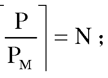
其中, P为所需的抽水功率, MW;
PM为一组功率调节电路满功率输出的功率, MW;
N为向上取整的功率调节电路的组数; 其中, N-1 组功率调节电路进行满功率输 出, 剩余 1组进行功率调节输出。 在启动 N组功率调节电路时, 并不是固定的从第 1组 按顺序启动前 N组, 也不是固定的某几组一直保持工作; 某一组在待命或者工作一段时 间后可以进行轮换工作状态, 这样可以保证各个功率调节电路可以进行轮换工作。
上述这种控制方式, 可以称之为: N-1+1 方式, 即为: N-1 组满功率工作, 最后 1 组承担调节功率任务; 通过这样的控制策略, 一部分功率调节电路工作, 另一部分功率 调节电路待命, 并且工作的电路与备用的电路可以进行定期轮换, 并不是固定的前几组 或者某几组工作, 这样让所有功率调节电路的设备交替工作, 相比较所有设备平均分配 都进行工作, 这种控制策略延长了各设备的工作寿命。
图 2A为本发明一实施例的功率调节电路组中一对一变压器的结构示意图。 图 2B为 本发明另一实施例的功率调节电路组中一对多变压器的结构示意图。 结合图 2A及图 2B 所示, 每一组功率调节电路 11包括: 一 IGBT整流器 31、 一平流电抗器 41、 一 IGBT 逆变器 51 ; IGBT整流器 31连接平流电抗器 41及 IGBT控制器 20; IGBT逆变器 51连 接平流电抗器 41及 IGBT控制器 20; 其中,
IGBT整流器 31, 用于将交流电整流为直流电;
平流电抗器 41, 用于将直流电进行平滑, 降低直流纹波系数;
IGBT逆变器 51, 用于将直流电逆变为功率及频率可变的交流电;
IGBT控制器 20, 用于控制 IGBT整流器 31及 IGBT逆变器 51的工作状态, 采用 PWM脉宽调制方式, 调节 IGBT逆变器 51的输出功率。
在本发明实施例中, 采用的 PWM脉宽调制方式的基本原理是: 对逆变器 51的通断 进行控制, 使输出端得到一系列幅值相等的脉冲, 用这些脉冲来代替正弦波或所需要的 波形。 也就是在输出波形的半个周期中产生多个脉冲, 使各脉冲的等值功率为正弦波 形, 所获得的输出平滑且低次谐波少。 按一定的规则对各脉冲的宽度进行调制, 即可改 变逆变电路输出电压的大小, 也可改变输出功率及频率。 PWM脉宽调制方式在现有技 术中已经是成熟的技术, 在此不再赘述。
在一具体实施例中, 功率调节电路组 10包括 15组功率调节电路 11。 每一所述 IGBT整流器 31 的额定输出功率为 20MW; 所述 IGBT逆变器 51 的额定输出功率为 20MW。
如图 2A所示, 功率调节电路组 10还包括: 多个换流变压器 21及多个升压变压器
61; 其中, 换流变压器 21可为三绕组变压器, 升压变压器 61可为双绕组变压器;
每一换流变压器 21分别连接一 IGBT整流器 31, 用于将电压降压至对应的 IGBT整 流器 31的所需电压;
每一升压变压器 61分别连接一 IGBT逆变器 51及抽水蓄能机组 3, 用于将对应的 IGBT逆变器 51的输出电压升压至抽水蓄能机组 3的额定电压。
如图 2B所示, 另一实施例中, 功率调节电路组 10中还可以设置一多绕组换流变压 器 21 '及一多绕组升压变压器 6Γ ; 原理同图 2A相同, 只是通过改变变压器绕组, 通过 多绕组变压器替代了前述的三绕组变压器和双绕组变压器, 减少了变压器的配置数量。
图 3为本发明另一实施例的抽水蓄能系统的整体结构示意图。 如图 3所示, 抽水蓄 能系统设置有主变压器 30及发电机同期断路器 40 (GCB) ; 发电机同期断路器 40连接 功率调节电路组 10中的换流变压器 21及主变压器 30, 主变压器 30连接电网 6。
在本实施例中, 抽水功率调节系统 1还包括一励磁控制器 50, 励磁控制器 50连接 IGBT控制器 20及抽水蓄能机组 3;
当 IGBT控制器 20根据调节功率调节电路组 10的输出功率时, 励磁控制器用于相 应的调节抽水蓄能机组 3的励磁电流及励磁电压, 使抽水蓄能机组 3工作稳定。
在本实施例中, 电站监控系统 2连接于 RTU系统 4, RTU系统 4与一电力调度系统 5进行通信; 其中,
电力调度系统 5根据电网 6的电网电力数据生成的自动控制指令;
RTU系统 4用于接收自动控制指令, 并生成抽水蓄能指令发送至电站监控系统 2。 另外, 工作人员还可人工输入人工控制指令至 RTU系统 4, RTU系统 4通过人工控
制指令生成抽水蓄能指令发送至电站监控系统 2。
图 4为本发明实施例的基于 IGBT控制的抽水功率调节方法流程图。 如图 4所示, 所述方法包括:
步骤 S401 , 获取抽水蓄能指令;
步骤 S402, 解析抽水蓄能指令, 获得所需的抽水功率;
步骤 S403, 根据抽水功率启动功率调节电路组中的 N组功率调节电路, 其中, N-1 组功率调节电路进行满功率输出, 剩余 1组功率调节电路进行功率调节输出, 使 N组功 率调节电路的输出功率达到抽水功率;
步骤 S404, 抽水蓄能机组根据抽水功率进行抽水蓄能。
在步骤 S403中, 根据抽水功率启动功率调节电路组中的 N组功率调节电路的计算 方法如下:

其中, P为所需的抽水功率, MW;
PM为一组功率调节电路满功率输出的功率, MW;
N为向上取整的功率调节电路的组数; 其中, N-1 组功率调节电路进行满功率输 出, 剩余 1组进行功率调节输出。 其中, 调节功率调节电路的输出功率是采用 PWM脉 宽调制方式。
在本实施例中, 方法还包括: 步骤 S4011 , 根据电网电力数据生成自动控制指令; 步骤 S4012, 根据自动控制指令, 生成抽水蓄能指令。
另外, 工作人员可以通过人工输入人工控制指令, 并根据人工控制指令生成抽水蓄 能指令;
在本实施例的在步骤 S403及步骤 S404中, 当调节电路的输出功率时, 相应的调节 抽水蓄能机组的励磁电流及励磁电压, 使抽水蓄能机组工作稳定。
图 5为本发明一具体实施例的抽水蓄能系统的整体电路图。 如图 5所示, 发电的工 作流程为: 水流冲动抽水蓄能机组, 发电机在发电方向发出电力, 经过 1G隔离刀闸、 发电机同期断路器, 将所发电力送入电网。
图 6为本发明一具体实施例的抽水蓄能系统的整体的局部电路图。 结合 5及图 6所 示, 抽水的工作流程为:
电力调度系统 (未绘示) 根据电网电力下达自动控制指令给 RTU系统 4; RTU系统
4根据自动控制指令生成抽水蓄能指令并发送至电站监控系统 2; 电站监控系统 2将抽水 蓄能指令下达给 IGBT控制器 20;
IGBT控制器 20解析后, 根据所需的抽水功率启动相应的功率调节电路; 同时, 下 达启动命令给励磁控制器 50, 通过励磁控制器 50调节抽水蓄能机组的励磁电流和励磁 电压; 其中, 功率调节电路的 IGBT整流器 31收到指令后开始整流工作, IGBT逆变器 也同步工作, 采用 PWM脉宽调制方式进行逆变调整, 使输出频率和输出功率逐步增加 到所需数值, 达到机组转速和输出功率与电网电力平衡。
当每一 IGBT整流器及 IGBT逆变器的额定输出功率为 20MW时, 以下以一具体实 施例来说明调节功率调节电路组的方法:
当所需抽水功率为 90MW时, 通过计算可得需要 5组功率调节电路, 则其中 4组满 功率工作, 剩余 1组输出为 10MW即可满足。
若所需抽水功率变为 95MW时, 则只需要将前述剩余 1组的输出调节为 15MW, 其 他 4组功率不变, 继续保持满功率工作。
若所需抽水功率变为 110MW时, 则需要再投入 1组功率调节电路, 则其中 5组满 功率工作, 第 6组即剩余 1组输出为 10MW即可。
当所需抽水功率逐步减少时, 则与上述调节方式相同, 先减少其中 1 组的功率, 如 果不能满足减功率的要求, 则可以逐组降低, 其余组仍保持满功率工作。
上述这种控制方式, 可以称之为: N-1+1 方式, 即为: N-1 组满功率工作, 最后 1 组承担调节功率; 通过这样的控制策略, 一部分功率调节电路工作, 另一部分功率调节 电路待命, 并且工作的电路可以进行定期轮换, 并不是固定的前几组或者某几组工作, 这样让所有功率调节电路的设备交替工作, 相比较所有设备平均分配都进行工作, 这种 控制方法延长了设备的工作寿命。
在本发明的实施例中, 依靠 IGBT控制器调节 IGBT逆变器就可以改变其输出相 序, 因此不再需要在抽水蓄能系统一次回路设置五极换相刀间来改变输出相序。 在本发 明实施例中, 因为 IGBT本身具备变频启动的功能, 所以不再需要额外配置 SFC变频抽 水启动回路。 在实际应用中, 当 IGBT制造技术提高后, 其电力换流容量和工作电压也 会相应提高, 所述配置的功率调节电路组可以相对减少。
通过本发明实施例的一种基于 IGBT控制的抽水功率调节系统及方法, 实现了抽水 工况变功率调节, 在抽水功率调节时达到与电网功率充抵平衡, 减少电网遭受风、 太阳 能等不稳定电力的冲击, 使得无论风大或小、 太阳能光强或弱, 电网频率都能保持稳
定。
以上所述的具体实施例, 对本发明的目的、 技术方案和有益效果进行了进一步详细 说明, 所应理解的是, 以上所述仅为本发明的具体实施例而已, 并不用于限定本发明的 保护范围, 凡在本发明的精神和原则之内, 所做的任何修改、 等同替换、 改进等, 均应 包含在本发明的保护范围之内。
Claims
1、 一种基于 IGBT控制的抽水功率调节系统, 其特征在于, 所述系统连接于电站监 控系统及抽水蓄能机组, 包括: IGBT控制器、 功率调节电路组; 所述功率调节电路组 包括多组功率调节电路; 其中,
所述 IGBT控制器用于接收所述电站监控系统输出的抽水蓄能指令, 并解析所述抽 水蓄能指令, 获得所需的抽水功率; 根据所述抽水功率启动所述功率调节电路组中的 N 组功率调节电路, 其中, N-1组功率调节电路进行满功率输出, 剩余 1组功率调节电路 进行功率调节输出, 使所述 N组功率调节电路的输出功率达到所述抽水功率;
所述功率调节电路组用于输出所述抽水功率至所述抽水蓄能机组, 所述抽水蓄能机 组根据所述抽水功率进行抽水工况运行。
2、 根据权利要求 1所述的系统, 其特征在于, 根据所述抽水功率启动所述功率调节 电路组中的 N组功率调节电路的计算方法如下:

其中, P为所需的抽水功率, MW;
PM为一组功率调节电路满功率输出的功率, MW;
N为向上取整的功率调节电路的组数; 其中, N-1 组功率调节电路进行满功率输 出, 剩余 1组进行功率调节输出。
3、 根据权利要求 1所述的系统, 其特征在于, 每一组所述功率调节电路包括: 一 IGBT整流器、 一平流电抗器、 一 IGBT逆变器; 所述 IGBT整流器连接平流电抗器及 IGBT控制器; 所述 IGBT逆变器连接平流电抗器及 IGBT控制器; 其中,
所述 IGBT整流器, 用于将交流电整流为直流电;
所述平流电抗器, 用于将所述直流电进行平滑, 降低直流纹波系数;
所述 IGBT逆变器, 用于将所述直流电逆变为功率及频率可变的交流电;
所述 IGBT控制器, 用于控制所述 IGBT整流器及所述 IGBT逆变器的工作状态, 采 用 PWM脉宽调制方式, 调节所述 IGBT逆变器的输出功率。
4、 根据权利要求 3所述的系统, 其特征在于, 所述功率调节电路组包括 15组功率 调节电路。
5、 根据权利要求 4所述的系统, 其特征在于, 每一所述 IGBT整流器的额定输出功
率为 20MW; 每一所述 IGBT逆变器的额定输出功率为 20MW。
6、 根据权利要求 3所述的系统, 其特征在于, 所述功率调节电路组还包括: 一换流 变压器及一升压变压器;
所述换流变压器连接 IGBT整流器, 用于将电压降压至 IGBT整流器的所需工作电 压;
所述升压变压器连接 IGBT逆变器及抽水蓄能机组, 用于将 IGBT逆变器的输出电 压升压至抽水蓄能机组的额定电压。
7、 根据权利要求 3所述的系统, 其特征在于, 所述功率调节电路组还包括: 多个换 流变压器及多个升压变压器; 其中,
每一所述换流变压器分别连接一所述 IGBT整流器, 用于将电压降压至对应的所述
IGBT整流器的所需工作电压;
每一所述升压变压器分别连接一所述 IGBT逆变器及所述抽水蓄能机组, 用于将对 应的所述 IGBT逆变器的输出电压升压至抽水蓄能机组的额定电压。
8、 根据权利要求 1所述的系统, 其特征在于, 所述电站监控系统连接于一 RTU系 统, 所述 RTU系统与一电力调度系统进行通信; 其中,
所述电力调度系统根据电网电力数据生成的自动控制指令;
所述 RTU系统用于接收自动控制指令, 并生成所述抽水蓄能指令发送至所述电站监 控系统。
9、 根据权利要求 1所述的系统, 其特征在于, 所述 RTU系统用于接收工作人员人 工输入的人工控制指令, 并生成所述抽水蓄能指令发送至所述电站监控系统。
10、 根据权利要求 1所述的系统, 其特征在于, 所述系统还包括一励磁控制器, 所 述励磁控制器连接 IGBT控制器及抽水蓄能机组;
当所述 IGBT控制器调节所述功率调节电路组的输出功率时, 所述励磁控制器用于 相应的调节所述抽水蓄能机组的励磁电流及励磁电压, 使所述抽水蓄能机组工作稳定。
11、 一种基于 IGBT控制的抽水功率调节方法, 其特征在于,
获取抽水蓄能指令;
解析所述抽水蓄能指令, 获得所需的抽水功率;
根据所述抽水功率启动功率调节电路组中的 N组功率调节电路, 其中, N-1组功率 调节电路进行满功率输出, 剩余 1组功率调节电路进行功率调节输出, 使所述 N组功率 调节电路的输出功率达到所述抽水功率;
抽水蓄能机组根据所述抽水功率进行抽水工况运行。
12、 根据权利要求 11所述的方法, 其特征在于, 根据设置的抽水功率启动所述功率 调节电路组中的 N组功率调节电路的计算方法如下:
丄 N ; 其中, P为所需的抽水功率, MW;
PM为一组功率调节电路满功率输出的功率, MW;
N为向上取整的功率调节电路的组数; 其中, N-1 组功率调节电路进行满功率输 出, 剩余 1组进行功率调节输出。
13、 根据权利要求 12所述的方法, 其特征在于, 根据所述抽水功率启动功率调节电 路组中的 N组功率调节电路, 其中, N-1组功率调节电路进行满功率输出, 剩余 1组功 率调节电路进行功率调节输出, 使所述 N组功率调节电路的输出功率达到所述抽水功率 包括:
采用 PWM脉宽调制方式, 调节所述功率调节电路的输出功率。
14、 根据权利要求 11所述的方法, 其特征在于, 所述获取抽水蓄能指令包括: 根据 电网电力数据生成自动控制指令, 根据所述自动控制指令, 生成所述抽水蓄能指令。
15、 根据权利要求 11所述的方法, 其特征在于, 所述获取抽水蓄能指令包括: 工作 人员人工输入人工控制指令, 并根据人工控制指令生成所述抽水蓄能指令。
16、 根据权利要求 11所述的方法, 其特征在于, 所述方法还包括: 当调节所述功率 调节电路组的输出功率时, 相应的调节所述抽水蓄能机组的励磁电流及励磁电压, 使所 述抽水蓄能机组工作稳定。
Priority Applications (1)
| Application Number | Priority Date | Filing Date | Title |
|---|---|---|---|
| PCT/CN2013/089409 WO2015085587A1 (zh) | 2013-12-13 | 2013-12-13 | 一种基于igbt控制的抽水功率调节系统及方法 |
Applications Claiming Priority (1)
| Application Number | Priority Date | Filing Date | Title |
|---|---|---|---|
| PCT/CN2013/089409 WO2015085587A1 (zh) | 2013-12-13 | 2013-12-13 | 一种基于igbt控制的抽水功率调节系统及方法 |
Publications (1)
| Publication Number | Publication Date |
|---|---|
| WO2015085587A1 true WO2015085587A1 (zh) | 2015-06-18 |
Family
ID=53370535
Family Applications (1)
| Application Number | Title | Priority Date | Filing Date |
|---|---|---|---|
| PCT/CN2013/089409 Ceased WO2015085587A1 (zh) | 2013-12-13 | 2013-12-13 | 一种基于igbt控制的抽水功率调节系统及方法 |
Country Status (1)
| Country | Link |
|---|---|
| WO (1) | WO2015085587A1 (zh) |
Cited By (2)
| Publication number | Priority date | Publication date | Assignee | Title |
|---|---|---|---|---|
| CN105119360A (zh) * | 2015-09-25 | 2015-12-02 | 浙江晶尚新能源科技有限公司 | 一种太阳能供电装置 |
| RU2840716C1 (ru) * | 2024-04-09 | 2025-05-28 | Акционерное общество "Государственный научный центр Российской Федерации "Исследовательский центр имени М.В. Келдыша" | Способ управления автономной системой электропитания |
Citations (3)
| Publication number | Priority date | Publication date | Assignee | Title |
|---|---|---|---|---|
| CN1290417A (zh) * | 1998-02-13 | 2001-04-04 | 罗伯特·博施有限公司 | 使直流电压转换器受控并联运行的装置和方法,特别适用于汽车的多级电压车载电网 |
| CN101924513A (zh) * | 2010-08-20 | 2010-12-22 | 上海交通大学 | 泵站水泵反向发电运行功率调节系统 |
| CN102315810A (zh) * | 2011-09-08 | 2012-01-11 | 上海交通大学 | 基于集成门极换向晶闸管的大功率抽水蓄能机组启动系统 |
-
2013
- 2013-12-13 WO PCT/CN2013/089409 patent/WO2015085587A1/zh not_active Ceased
Patent Citations (3)
| Publication number | Priority date | Publication date | Assignee | Title |
|---|---|---|---|---|
| CN1290417A (zh) * | 1998-02-13 | 2001-04-04 | 罗伯特·博施有限公司 | 使直流电压转换器受控并联运行的装置和方法,特别适用于汽车的多级电压车载电网 |
| CN101924513A (zh) * | 2010-08-20 | 2010-12-22 | 上海交通大学 | 泵站水泵反向发电运行功率调节系统 |
| CN102315810A (zh) * | 2011-09-08 | 2012-01-11 | 上海交通大学 | 基于集成门极换向晶闸管的大功率抽水蓄能机组启动系统 |
Cited By (3)
| Publication number | Priority date | Publication date | Assignee | Title |
|---|---|---|---|---|
| CN105119360A (zh) * | 2015-09-25 | 2015-12-02 | 浙江晶尚新能源科技有限公司 | 一种太阳能供电装置 |
| RU2840716C1 (ru) * | 2024-04-09 | 2025-05-28 | Акционерное общество "Государственный научный центр Российской Федерации "Исследовательский центр имени М.В. Келдыша" | Способ управления автономной системой электропитания |
| RU2840716C9 (ru) * | 2024-04-09 | 2025-07-07 | Акционерное общество "Государственный научный центр Российской Федерации "Исследовательский центр имени М.В. Келдыша" | Способ управления автономной системой электропитания |
Similar Documents
| Publication | Publication Date | Title |
|---|---|---|
| CN101924513B (zh) | 泵站水泵反向发电运行功率调节系统 | |
| EP2400619A2 (en) | Low cost current source converters for power generation application | |
| CN102255586B (zh) | 永磁同步电机恒功率宽调速控制方法 | |
| CN101924508A (zh) | 大功率抽水蓄能机组启动用变频调速系统 | |
| WO2011147128A1 (zh) | 电能变换装置 | |
| CN102386633A (zh) | 兆瓦级直驱型鼠笼异步发电机交-直-交风力发电系统 | |
| CN106786783A (zh) | 一种全功率风电并网系统及控制方法 | |
| CN112671014B (zh) | 飞轮储能变速发电系统 | |
| CN106356889A (zh) | 永磁风力发电机组 | |
| CN101860210A (zh) | 一种新型的升压斩波电路级联结构 | |
| CN101854065B (zh) | 一种级联型升压斩波电路的控制方法 | |
| CN103633667B (zh) | 一种基于igbt控制的抽水功率调节系统及方法 | |
| CN102324883A (zh) | 一种抽水蓄能电站静止变频启动功率因数最优控制方法 | |
| CN202756165U (zh) | 一种水轮机组变速运行系统 | |
| CN102315810A (zh) | 基于集成门极换向晶闸管的大功率抽水蓄能机组启动系统 | |
| CN201150043Y (zh) | 开关磁阻风力发电装置 | |
| CN204441903U (zh) | 一种交直流混合的清洁能源系统 | |
| WO2015085587A1 (zh) | 一种基于igbt控制的抽水功率调节系统及方法 | |
| CN202150822U (zh) | 用于永磁同步电机恒功率宽调速控制的四象限变频器主电路 | |
| CN106532777A (zh) | 一种新型高压直流风力发电机组及组网 | |
| CN113889998B (zh) | 一种直流风电场开关磁阻电机变流系统及其控制方法 | |
| CN204992616U (zh) | 一种机侧网侧互为备用的变速恒频发电机组变流器 | |
| CN205099422U (zh) | 一种反渗透海水淡化自适应控制系统 | |
| CN204089213U (zh) | 宽转速范围直驱风力发电系统 | |
| CN103337854A (zh) | 基于中频逆变的柔性直流输电接入方法 |
Legal Events
| Date | Code | Title | Description |
|---|---|---|---|
| 121 | Ep: the epo has been informed by wipo that ep was designated in this application |
Ref document number: 13899329 Country of ref document: EP Kind code of ref document: A1 |
|
| NENP | Non-entry into the national phase |
Ref country code: DE |
|
| 122 | Ep: pct application non-entry in european phase |
Ref document number: 13899329 Country of ref document: EP Kind code of ref document: A1 |