WO2015083306A1 - 光反射性異方性導電接着剤、ジグリシジルイソシアヌリル変性環状ポリシロキサンの製造方法、及び発光装置 - Google Patents
光反射性異方性導電接着剤、ジグリシジルイソシアヌリル変性環状ポリシロキサンの製造方法、及び発光装置 Download PDFInfo
- Publication number
- WO2015083306A1 WO2015083306A1 PCT/JP2014/004510 JP2014004510W WO2015083306A1 WO 2015083306 A1 WO2015083306 A1 WO 2015083306A1 JP 2014004510 W JP2014004510 W JP 2014004510W WO 2015083306 A1 WO2015083306 A1 WO 2015083306A1
- Authority
- WO
- WIPO (PCT)
- Prior art keywords
- light
- anisotropic conductive
- particles
- reflective
- conductive adhesive
- Prior art date
- Legal status (The legal status is an assumption and is not a legal conclusion. Google has not performed a legal analysis and makes no representation as to the accuracy of the status listed.)
- Ceased
Links
Images


Classifications
-
- C—CHEMISTRY; METALLURGY
- C07—ORGANIC CHEMISTRY
- C07F—ACYCLIC, CARBOCYCLIC OR HETEROCYCLIC COMPOUNDS CONTAINING ELEMENTS OTHER THAN CARBON, HYDROGEN, HALOGEN, OXYGEN, NITROGEN, SULFUR, SELENIUM OR TELLURIUM
- C07F7/00—Compounds containing elements of Groups 4 or 14 of the Periodic Table
- C07F7/02—Silicon compounds
- C07F7/21—Cyclic compounds having at least one ring containing silicon, but no carbon in the ring
-
- C—CHEMISTRY; METALLURGY
- C07—ORGANIC CHEMISTRY
- C07F—ACYCLIC, CARBOCYCLIC OR HETEROCYCLIC COMPOUNDS CONTAINING ELEMENTS OTHER THAN CARBON, HYDROGEN, HALOGEN, OXYGEN, NITROGEN, SULFUR, SELENIUM OR TELLURIUM
- C07F7/00—Compounds containing elements of Groups 4 or 14 of the Periodic Table
- C07F7/02—Silicon compounds
- C07F7/08—Compounds having one or more C—Si linkages
- C07F7/0834—Compounds having one or more O-Si linkage
- C07F7/0838—Compounds with one or more Si-O-Si sequences
-
- C—CHEMISTRY; METALLURGY
- C08—ORGANIC MACROMOLECULAR COMPOUNDS; THEIR PREPARATION OR CHEMICAL WORKING-UP; COMPOSITIONS BASED THEREON
- C08L—COMPOSITIONS OF MACROMOLECULAR COMPOUNDS
- C08L83/00—Compositions of macromolecular compounds obtained by reactions forming in the main chain of the macromolecule a linkage containing silicon with or without sulfur, nitrogen, oxygen or carbon only; Compositions of derivatives of such polymers
- C08L83/04—Polysiloxanes
- C08L83/08—Polysiloxanes containing silicon bound to organic groups containing atoms other than carbon, hydrogen and oxygen
-
- C—CHEMISTRY; METALLURGY
- C09—DYES; PAINTS; POLISHES; NATURAL RESINS; ADHESIVES; COMPOSITIONS NOT OTHERWISE PROVIDED FOR; APPLICATIONS OF MATERIALS NOT OTHERWISE PROVIDED FOR
- C09J—ADHESIVES; NON-MECHANICAL ASPECTS OF ADHESIVE PROCESSES IN GENERAL; ADHESIVE PROCESSES NOT PROVIDED FOR ELSEWHERE; USE OF MATERIALS AS ADHESIVES
- C09J11/00—Features of adhesives not provided for in group C09J9/00, e.g. additives
- C09J11/02—Non-macromolecular additives
- C09J11/04—Non-macromolecular additives inorganic
-
- C—CHEMISTRY; METALLURGY
- C09—DYES; PAINTS; POLISHES; NATURAL RESINS; ADHESIVES; COMPOSITIONS NOT OTHERWISE PROVIDED FOR; APPLICATIONS OF MATERIALS NOT OTHERWISE PROVIDED FOR
- C09J—ADHESIVES; NON-MECHANICAL ASPECTS OF ADHESIVE PROCESSES IN GENERAL; ADHESIVE PROCESSES NOT PROVIDED FOR ELSEWHERE; USE OF MATERIALS AS ADHESIVES
- C09J9/00—Adhesives characterised by their physical nature or the effects produced, e.g. glue sticks
- C09J9/02—Electrically-conducting adhesives
-
- H—ELECTRICITY
- H10—SEMICONDUCTOR DEVICES; ELECTRIC SOLID-STATE DEVICES NOT OTHERWISE PROVIDED FOR
- H10H—INORGANIC LIGHT-EMITTING SEMICONDUCTOR DEVICES HAVING POTENTIAL BARRIERS
- H10H20/00—Individual inorganic light-emitting semiconductor devices having potential barriers, e.g. light-emitting diodes [LED]
- H10H20/80—Constructional details
- H10H20/85—Packages
- H10H20/855—Optical field-shaping means, e.g. lenses
- H10H20/856—Reflecting means
-
- H—ELECTRICITY
- H10—SEMICONDUCTOR DEVICES; ELECTRIC SOLID-STATE DEVICES NOT OTHERWISE PROVIDED FOR
- H10H—INORGANIC LIGHT-EMITTING SEMICONDUCTOR DEVICES HAVING POTENTIAL BARRIERS
- H10H20/00—Individual inorganic light-emitting semiconductor devices having potential barriers, e.g. light-emitting diodes [LED]
- H10H20/80—Constructional details
- H10H20/85—Packages
- H10H20/857—Interconnections, e.g. lead-frames, bond wires or solder balls
-
- C—CHEMISTRY; METALLURGY
- C08—ORGANIC MACROMOLECULAR COMPOUNDS; THEIR PREPARATION OR CHEMICAL WORKING-UP; COMPOSITIONS BASED THEREON
- C08G—MACROMOLECULAR COMPOUNDS OBTAINED OTHERWISE THAN BY REACTIONS ONLY INVOLVING UNSATURATED CARBON-TO-CARBON BONDS
- C08G77/00—Macromolecular compounds obtained by reactions forming a linkage containing silicon with or without sulfur, nitrogen, oxygen or carbon in the main chain of the macromolecule
- C08G77/04—Polysiloxanes
- C08G77/38—Polysiloxanes modified by chemical after-treatment
- C08G77/382—Polysiloxanes modified by chemical after-treatment containing atoms other than carbon, hydrogen, oxygen or silicon
- C08G77/388—Polysiloxanes modified by chemical after-treatment containing atoms other than carbon, hydrogen, oxygen or silicon containing nitrogen
-
- C—CHEMISTRY; METALLURGY
- C08—ORGANIC MACROMOLECULAR COMPOUNDS; THEIR PREPARATION OR CHEMICAL WORKING-UP; COMPOSITIONS BASED THEREON
- C08K—Use of inorganic or non-macromolecular organic substances as compounding ingredients
- C08K3/00—Use of inorganic substances as compounding ingredients
- C08K3/30—Sulfur-, selenium- or tellurium-containing compounds
- C08K2003/3009—Sulfides
-
- C—CHEMISTRY; METALLURGY
- C08—ORGANIC MACROMOLECULAR COMPOUNDS; THEIR PREPARATION OR CHEMICAL WORKING-UP; COMPOSITIONS BASED THEREON
- C08K—Use of inorganic or non-macromolecular organic substances as compounding ingredients
- C08K3/00—Use of inorganic substances as compounding ingredients
- C08K3/10—Metal compounds
-
- C—CHEMISTRY; METALLURGY
- C08—ORGANIC MACROMOLECULAR COMPOUNDS; THEIR PREPARATION OR CHEMICAL WORKING-UP; COMPOSITIONS BASED THEREON
- C08K—Use of inorganic or non-macromolecular organic substances as compounding ingredients
- C08K3/00—Use of inorganic substances as compounding ingredients
- C08K3/18—Oxygen-containing compounds, e.g. metal carbonyls
- C08K3/20—Oxides; Hydroxides
- C08K3/22—Oxides; Hydroxides of metals
-
- C—CHEMISTRY; METALLURGY
- C08—ORGANIC MACROMOLECULAR COMPOUNDS; THEIR PREPARATION OR CHEMICAL WORKING-UP; COMPOSITIONS BASED THEREON
- C08K—Use of inorganic or non-macromolecular organic substances as compounding ingredients
- C08K3/00—Use of inorganic substances as compounding ingredients
- C08K3/28—Nitrogen-containing compounds
-
- H—ELECTRICITY
- H10—SEMICONDUCTOR DEVICES; ELECTRIC SOLID-STATE DEVICES NOT OTHERWISE PROVIDED FOR
- H10H—INORGANIC LIGHT-EMITTING SEMICONDUCTOR DEVICES HAVING POTENTIAL BARRIERS
- H10H20/00—Individual inorganic light-emitting semiconductor devices having potential barriers, e.g. light-emitting diodes [LED]
- H10H20/80—Constructional details
- H10H20/84—Coatings, e.g. passivation layers or antireflective coatings
- H10H20/841—Reflective coatings, e.g. dielectric Bragg reflectors
-
- H—ELECTRICITY
- H10—SEMICONDUCTOR DEVICES; ELECTRIC SOLID-STATE DEVICES NOT OTHERWISE PROVIDED FOR
- H10W—GENERIC PACKAGES, INTERCONNECTIONS, CONNECTORS OR OTHER CONSTRUCTIONAL DETAILS OF DEVICES COVERED BY CLASS H10
- H10W72/00—Interconnections or connectors in packages
- H10W72/851—Dispositions of multiple connectors or interconnections
- H10W72/874—On different surfaces
- H10W72/884—Die-attach connectors and bond wires
-
- H—ELECTRICITY
- H10—SEMICONDUCTOR DEVICES; ELECTRIC SOLID-STATE DEVICES NOT OTHERWISE PROVIDED FOR
- H10W—GENERIC PACKAGES, INTERCONNECTIONS, CONNECTORS OR OTHER CONSTRUCTIONAL DETAILS OF DEVICES COVERED BY CLASS H10
- H10W74/00—Encapsulations, e.g. protective coatings
- H10W74/10—Encapsulations, e.g. protective coatings characterised by their shape or disposition
- H10W74/15—Encapsulations, e.g. protective coatings characterised by their shape or disposition on active surfaces of flip-chip devices, e.g. underfills
-
- H—ELECTRICITY
- H10—SEMICONDUCTOR DEVICES; ELECTRIC SOLID-STATE DEVICES NOT OTHERWISE PROVIDED FOR
- H10W—GENERIC PACKAGES, INTERCONNECTIONS, CONNECTORS OR OTHER CONSTRUCTIONAL DETAILS OF DEVICES COVERED BY CLASS H10
- H10W90/00—Package configurations
- H10W90/701—Package configurations characterised by the relative positions of pads or connectors relative to package parts
- H10W90/721—Package configurations characterised by the relative positions of pads or connectors relative to package parts of bump connectors
- H10W90/724—Package configurations characterised by the relative positions of pads or connectors relative to package parts of bump connectors between a chip and a stacked insulating package substrate, interposer or RDL
-
- H—ELECTRICITY
- H10—SEMICONDUCTOR DEVICES; ELECTRIC SOLID-STATE DEVICES NOT OTHERWISE PROVIDED FOR
- H10W—GENERIC PACKAGES, INTERCONNECTIONS, CONNECTORS OR OTHER CONSTRUCTIONAL DETAILS OF DEVICES COVERED BY CLASS H10
- H10W90/00—Package configurations
- H10W90/701—Package configurations characterised by the relative positions of pads or connectors relative to package parts
- H10W90/731—Package configurations characterised by the relative positions of pads or connectors relative to package parts of die-attach connectors
- H10W90/734—Package configurations characterised by the relative positions of pads or connectors relative to package parts of die-attach connectors between a chip and a stacked insulating package substrate, interposer or RDL
-
- H—ELECTRICITY
- H10—SEMICONDUCTOR DEVICES; ELECTRIC SOLID-STATE DEVICES NOT OTHERWISE PROVIDED FOR
- H10W—GENERIC PACKAGES, INTERCONNECTIONS, CONNECTORS OR OTHER CONSTRUCTIONAL DETAILS OF DEVICES COVERED BY CLASS H10
- H10W90/00—Package configurations
- H10W90/701—Package configurations characterised by the relative positions of pads or connectors relative to package parts
- H10W90/751—Package configurations characterised by the relative positions of pads or connectors relative to package parts of bond wires
- H10W90/754—Package configurations characterised by the relative positions of pads or connectors relative to package parts of bond wires between a chip and a stacked insulating package substrate, interposer or RDL
Definitions
- the present invention relates to a light-reflective anisotropic conductive adhesive used for anisotropic conductive connection of a light-emitting element to a wiring board, and a diglycidyl isocyanuryl-modified cyclic polysiloxane contained in the adhesive.
- the present invention relates to a method for producing glycidyl isocyanuryl-modified cyclic polysiloxane and a light emitting device in which a light emitting element is mounted on a wiring board using the adhesive.
- a light emitting device using a light emitting diode (LED) element is widely used, and the structure of an old type light emitting device is such that, as shown in FIG. 3, an LED element 33 is bonded to a substrate 31 with a die bond adhesive 32, The p electrode 34 and the n electrode 35 on the upper surface are wire-bonded to the connection terminal 36 of the substrate 31 with a gold wire 37, and the entire LED element 33 is sealed with a transparent mold resin 38.
- the gold wire 37 absorbs light having a wavelength of 400 to 500 nm emitted from the LED element 33 to the upper surface side, and a part of the light emitted to the lower surface side. Is absorbed by the die-bonding adhesive 32 and the luminous efficiency of the LED element 33 is reduced.
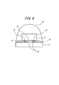
- the LED element 33 is flip-chip mounted as shown in FIG. 4 from the viewpoint of improving the light emission efficiency regarding the light reflection of the LED element (Patent Document 1).
- bumps 39 are formed on the p electrode 34 and the n electrode 35, respectively, and further, the bump formation surface of the LED element 33 is insulated from the p electrode 34 and the n electrode 35.
- the light reflecting layer 40 is provided on the surface.
- the LED element 33 and the substrate 31 are connected and fixed by using an anisotropic conductive paste 41 or an anisotropic conductive film (not shown) and curing them. For this reason, in the light emitting device of FIG. 4, the light emitted upward of the LED element 33 is not absorbed by the gold wire, and most of the light emitted downward is reflected by the light reflecting layer 40 and emitted upward.
- the light emission efficiency does not decrease.
- the anisotropic conductive paste used for mounting the LED element and the insulating resin component in the anisotropic conductive film are accompanied by discoloration due to heat or light.
- a two-component curable methylsilicone resin or a two-component curable phenylsilicone resin excellent in heat resistance and light resistance is used as an anisotropic conductive paste, Attempts have been made to employ an insulating resin component in an anisotropic conductive film.
- the light reflecting layer 40 must be provided on the LED element 33 by a metal vapor deposition method or the like so as to be insulated from the p-electrode 34 and the n-electrode 35, and thus an increase in manufacturing cost is inevitable.
- the surface of the conductive particles coated with gold, nickel or copper in the cured anisotropic conductive paste or anisotropic conductive film is brown or
- the epoxy resin binder itself which exhibits a dark brown color and in which conductive particles are dispersed, also exhibits a brown color because of the imidazole-based latent curing agent that is commonly used for its curing. There is a problem that it is difficult to improve the light emission efficiency (light extraction efficiency).
- An object of the present invention is to solve the above-described problems of the prior art, and light-emitting elements such as light-emitting diodes (LEDs) are flip-chip mounted on a wiring board using an anisotropic conductive adhesive to emit light.
- LEDs light-emitting diodes
- An object is to provide an anisotropic conductive adhesive and a light emitting device in which a light emitting element is flip-chip mounted on a wiring board using the adhesive.
- the inventors of the present invention have assumed that the anisotropic conductive adhesive itself has a light reflecting function, and the light-reflective insulating particles are added to the anisotropic conductive adhesive under the assumption that the luminous efficiency can be prevented. It has been found that by blending, the luminous efficiency of the light emitting device can be prevented from being lowered.
- the present inventors have used anisotropic conductive adhesive by heat or light by using diglycidyl isocyanuryl-modified cyclic polysiloxane having a specific structure as an insulating adhesive component of anisotropic conductive adhesive. It has been found that the agent can be prevented from being discolored and exhibit a practically sufficient die shear strength. And based on these knowledge, it came to complete this invention.
- the present invention is a light-reflective anisotropic conductive adhesive used for anisotropic conductive connection of a light-emitting element to a wiring board, comprising a thermosetting resin composition, conductive particles, and light-reflective insulating particles.
- the thermosetting resin composition contains a diglycidyl isocyanuryl-modified cyclic polysiloxane represented by the formula (1) and a curing agent for epoxy resin, and is a light-reflective anisotropic material
- An electrically conductive adhesive is provided.
- R is an alkyl group or an aryl group
- n is an integer of 3 to 40
- the arc connecting Si and O indicates that the polysiloxane is cyclic.
- this light-reflective anisotropic conductive adhesive core particles in which conductive particles are coated with a metal material, and titanium oxide particles, boron nitride, and zinc oxide particles on the surface thereof are used.
- a light-reflective anisotropic conductive adhesive which is a light-reflective conductive particle comprising a light-reflecting layer formed of at least one inorganic particle selected from the group consisting of aluminum oxide particles.
- the present invention relates to a method for producing a diglycidyl isocyanuryl-modified cyclic polysiloxane of formula (1), wherein the hydrogen cyclic polysiloxane of formula (a) and 1-allyl-3,
- a production method characterized by uniformly mixing 5-diglycidyl isocyanurate with a hydrosilylation reaction in the presence of 20 ppm or less of a platinum catalyst.
- R is an alkyl group or an aryl group
- n is an integer of 3 to 40.
- the arc connecting Si and O in the formula indicates that the polysiloxane is cyclic.
- the present invention provides a light emitting device in which a light emitting element is mounted on a wiring board by a flip chip method through the above-described light reflective anisotropic conductive adhesive.
- the light-reflective anisotropic conductive adhesive of the present invention used for anisotropically conductively connecting a light-emitting element to a wiring board includes a thermosetting resin composition as a binder, light-reflective insulating particles, and conductive particles. Containing.
- This thermosetting resin composition contains diglycidyl isocyanuryl-modified cyclic polysiloxane represented by the formula (1) that is cured by a curing agent for epoxy resin.
- This cyclic polysiloxane has a structure in which a diglycidyl isocyanuryl alkyl group is bonded to the polysiloxane ring. Because of such a structure, the reason is not clear, but the anisotropic conductive adhesive can be prevented from being discolored by heat or light, and a practically sufficient die shear strength can be realized.
- the light-reflective anisotropic conductive adhesive of the present invention contains light-reflective insulating particles, it can reflect light.
- the light-reflective insulating particles are at least one inorganic particle selected from the group consisting of titanium oxide, boron nitride, zinc oxide and aluminum oxide, or a resin in which the surface of scaly or spherical metal particles is coated with an insulating resin.
- coated metal particles since the particles themselves are almost white, the wavelength dependency of the reflection characteristic with respect to visible light is small, so that the light emission efficiency can be improved and the light emission color of the light emitting element remains unchanged. Can be reflected by color.
- the conductive particles are formed of core particles coated with a metal material, and at least one inorganic particle selected from the group consisting of titanium oxide particles, boron nitride particles, zinc oxide particles, and aluminum oxide particles on the surface thereof.
- the light-reflective conductive particles composed of a white to gray light-reflecting layer
- the light-reflective conductive particles themselves exhibit white to gray, so the wavelength dependence of the reflection characteristics for visible light Therefore, the light emission efficiency can be further improved, and the emission color of the light emitting element can be reflected with the same color.
- the present invention is a light-reflective anisotropic conductive adhesive used for anisotropically conductively connecting a light-emitting element to a wiring board, and includes a thermosetting resin composition, conductive particles, and light-reflective insulating particles. It is a light-reflective anisotropic conductive adhesive.
- thermosetting resin composition that is a binder will be described.
- thermosetting resin composition contains diglycidyl isocyanuryl-modified cyclic polysiloxane represented by the formula (1) and a curing agent for epoxy resin.
- diglycidyl isocyanuryl-modified cyclic polysiloxane represented by the formula (1) it is possible to prevent the anisotropic conductive adhesive from being discolored by heat or light, and a practically sufficient die shear strength. Can be realized.
- R is an alkyl group such as a lower alkyl group having 1 to 6 carbon atoms, or an aryl group such as a carbocyclic aromatic group or a heterocyclic aromatic group.
- the alkyl group include a methyl group, an ethyl group, a propyl group, an isopropyl group, a butyl group, and an isobutyl group, and a particularly preferable alkyl group is a methyl group.
- a preferred specific example of the aryl group is a phenyl group.
- n is an integer of 3 to 40, preferably an integer of 3 to 20, and more preferably 4.
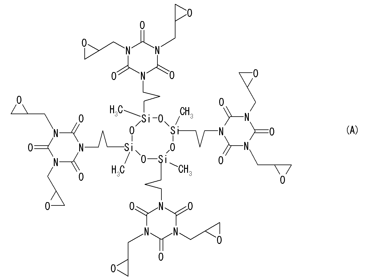
- particularly preferred diglycidyl isocyanuryl-modified cyclic polysiloxane of the formula (1) is a compound represented by the following formula (A).
- the amount is preferably 45 to 65% by mass, more preferably 50 to 60% by mass.
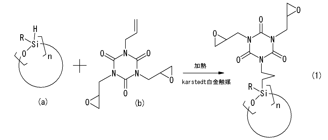
- the diglycidyl isocyanuryl-modified cyclic polysiloxane represented by the formula (1) includes a hydrogen cyclic polysiloxane of the formula (a) and 1-allyl-3 of the formula (b) as shown in the following reaction formula: , 5-diglycidyl isocyanurate, in an inert gas atmosphere such as nitrogen, in a suitable solvent, preferably without solvent, in the presence of a platinum catalyst capable of catalyzing hydrosilylation, Preferably, it can be produced by heating to room temperature to 150 ° C. to cause a hydrosilylation reaction. From the reaction mixture, the compound of the formula (1) can be isolated by a conventional method (concentration treatment, column treatment, etc.). In addition, the substituent in reaction formula is as having already demonstrated in relation to Formula (1).
- the concentration of the platinum catalyst in the hydrosilylation reaction is 20 ppm or less, preferably 15 ppm or less, particularly preferably 10 ppm or less.
- the preferable lower limit concentration of the platinum catalyst is at least 1.0 ppm. If the concentration of the platinum catalyst is within this range, the hydrosilylation reaction can proceed smoothly, and coloring of the light-reflective anisotropic conductive adhesive by heat or light can be suppressed without impairing adhesion. it can.
- the concentration of the platinum catalyst is a concentration in the mixture of the hydrogen cyclic polysiloxane at the start of the reaction and the epoxy group-containing isocyanurate having a terminal unsaturated alkenyl group.
- the concentration (Pt) of the platinum catalyst is very small relative to the hydrogen cyclic polysiloxane and the epoxy group-containing isocyanurate having a terminal unsaturated alkenyl group
- the mass of the hydrogen cyclic polysiloxane is set to W1.
- W2 the mass of the epoxy group-containing isocyanurate having a terminal unsaturated alkenyl group
- W3 the mass of the solid content of the platinum catalyst used
- the platinum catalyst may remain in the epoxy group-containing isocyanuryl-modified cyclic polysiloxane depending on the isolation / purification method of the reaction mixture.
- the platinum catalyst residual concentration is preferably 20 ppm. Hereinafter, it is more preferably 15 ppm or less. Thereby, it is possible to obtain a colorless and transparent resin without coloring.
- the residual platinum catalyst concentration in the epoxy group-containing isocyanuryl-modified cyclic polysiloxane should be measured using a commercially available inductively coupled plasma emission spectrometer (for example, Agilent 7500cx ICP-MS, manufactured by Agilent Technologies). Can do.
- Platinum catalyst example examples of platinum catalysts that can catalyze hydrosilylation include negatively charged complexes, zero-valent, divalent or tetravalent platinum compounds and platinum colloids. Negatively charged complexes include platinum carbonyl cluster anion compounds such as [Pt 3 (CO) 6 ] 2 ⁇ , [Pt 3 (CO) 6 ] 2 2 ⁇ , [Pt 3 (CO) 6 ] 4. 2- is exemplified. Examples of the zerovalent platinum compound include platinum (0) divinyltetramethyldisiloxane complex, platinum (0) tetravinyltetramethylcyclotetrasiloxane complex, platinum (0) ethylene complex, and platinum (0) styrene complex.
- Examples of divalent platinum compounds include Pt (II) Cl 2 , Pt (II) Br 2 , bis (ethylene) Pt (II) Cl 2 , (1,5-cyclooctadiene) Pt (II) Cl 2 , platinum (II) Acetylacetonate, bis (benzonitrile) Pt (II) Cl 2 is exemplified.
- Examples of the tetravalent platinum compound include Pt (IV) Cl 4 , H 2 Pt (IV) Cl 6 , Na 2 Pt (IV) Cl 6 , and K 2 Pt (IV) Cl 6 .
- a Karstedt platinum catalyst (1,3-divinyl-1,1,3,3-tetramethyldisiloxane platinum (0) complex) can be preferably used. These can be used as a solution dissolved in a solvent such as xylene as necessary.
- thermosetting resin composition is a heterocyclic epoxy compound, an alicyclic epoxy compound, or a hydrogenated epoxy as long as the effects of the invention are not impaired.
- a compound etc. can be contained.
- heterocyclic epoxy compound examples include an epoxy compound having a triazine ring.
- 1,3,5-tris (2,3-epoxypropyl) -1,3,5-triazine-2,4, 6- (1H, 3H, 5H) -trione (in other words triglycidyl isocyanurate) can be mentioned.
- Preferred examples of the alicyclic epoxy compound include those having two or more epoxy groups in the molecule. These may be liquid or solid. Among these, glycidyl hexahydrobisphenol A, 3,4-epoxycyclohexenylmethyl-3 ′, 4 is preferable because it can ensure light transmission suitable for mounting LED elements on the cured product and is excellent in rapid curing. '-Epoxycyclohexenecarboxylate can be preferably used.
- hydrogenated epoxy compound hydrogenated products of the aforementioned heterocyclic epoxy compounds and alicyclic epoxy compounds, and other known hydrogenated epoxy resins can be used.
- alicyclic epoxy compounds, heterocyclic epoxy compounds and hydrogenated epoxy compounds may be used alone or in combination with the diglycidyl isocyanuryl modified cyclic polysiloxane of formula (1). You may use together. In addition to these epoxy compounds, other epoxy compounds may be used in combination as long as the effects of the present invention are not impaired.
- the curing agent for epoxy resin As the curing agent for epoxy resin, a known curing agent for epoxy resin can be used.
- acid anhydride curing agents can be preferably used from the viewpoints of light transmittance, heat resistance, and the like.
- Acid anhydride curing agents include succinic anhydride, phthalic anhydride, maleic anhydride, trimellitic anhydride, pyromellitic anhydride, hexahydrophthalic anhydride, 3-methyl-hexahydrophthalic anhydride, 4-methyl-hexahydro Phthalic anhydride, or a mixture of 4-methyl-hexahydrophthalic anhydride and hexahydrophthalic anhydride, tetrahydrophthalic anhydride, methyl-tetrahydrophthalic anhydride, nadic anhydride, methyl nadic anhydride, norbornane-2,3-dicarboxylic acid An acid anhydride, methylnorbornane-2,3-dicarboxylic acid anhydride, methylcyclohexene dicarboxylic acid anhydride, etc. can be mentioned.
- the amount of the epoxy resin curing agent such as an acid anhydride curing agent in the thermosetting resin composition is 100 parts by mass of the diglycidyl isocyanuryl-modified cyclic polysiloxane represented by the formula (1). If the amount is too small, the amount of the uncured epoxy component tends to be excessive. If the amount is too large, the corrosion of the adherend material tends to be accelerated by the influence of the excess curing agent. More preferably, it is 60 to 100 parts by mass.
- the thermosetting resin composition can contain a known curing accelerator in order to complete the curing reaction smoothly and in a short time.
- Preferred curing accelerators include quaternary phosphonium salt-based curing accelerators and imidazole diameter curing accelerators.
- quaternary phosphonium bromide salt (“U-CAT5003” (trademark), manufactured by San Apro Co., Ltd.), 2-ethyl-4-methylimidazole and the like can be mentioned.
- an imidazole curing accelerator can be preferably used as a curing accelerator for an acid anhydride curing agent.
- the imidazole curing accelerator is preferably 0.20 to 2.00 parts by mass, and more preferably 0.60 to 1.00 parts by mass with respect to parts.
- thermosetting resin composition described above is preferably as colorless and transparent as possible. This is because the light reflecting efficiency of the light-reflective conductive particles in the anisotropic conductive adhesive is reflected without reducing the light color of the incident light.
- colorless and transparent means that the cured product of the anisotropic conductive adhesive has a light transmittance (JIS K7105) of 80% or more, preferably 90% or more with respect to visible light having a wavelength of 380 to 780 nm.
- the light-reflective insulating particles contained in the light-reflective anisotropic conductive adhesive of the present invention are for reflecting light incident on the anisotropic conductive adhesive to the outside.
- the light-reflective particles include metal particles, particles coated with metal particles, inorganic particles such as metal oxides, metal nitrides, and metal sulfides that are gray to white under natural light, resin core particles
- corrugation on the surface are contained irrespective of the material of particle
- the light-reflective insulating particles that can be used in the present invention do not include metal particles that are not covered with insulation because they are required to exhibit insulating properties.
- Preferred examples of such light-reflective insulating particles include at least selected from the group consisting of titanium oxide (TiO 2 ), boron nitride (BN), zinc oxide (ZnO), and aluminum oxide (Al 2 O 3 ).
- TiO 2 is preferably used from the viewpoint of a high refractive index.
- the shape of the light-reflective insulating particles may be spherical, scaly, indeterminate, acicular, etc. In consideration of reflection efficiency, spherical and scaly are preferable. In the case of a spherical shape, if it is too small, the reflectance is low, and if it is too large, the anisotropic conductive connection tends to be inhibited. Therefore, it is preferably 0.02 to 20 ⁇ m, more preferably 0.
- the major axis is preferably 0.1 to 100 ⁇ m, more preferably 1 to 50 ⁇ m, and the minor axis is preferably 0.01 to 10 ⁇ m, more preferably 0.1 to The thickness is preferably 5 ⁇ m, and the thickness is preferably 0.01 to 10 ⁇ m, more preferably 0.1 to 5 ⁇ m.
- the light-reflective insulating particles made of inorganic particles have a refractive index (JIS K7142) that is preferably larger than the refractive index of a cured product of the thermosetting resin composition (JIS K7142), more preferably at least 0.02. It is preferable that the degree is large. This is because when the difference in refractive index is small, the reflection efficiency at the interface between them decreases.
- the inorganic particles described above may be used, but resin-coated metal particles obtained by coating the surface of scale-like or spherical metal particles with a transparent insulating resin may be used.
- the metal particles include nickel, silver, and aluminum.
- the shape of the particles include an indefinite shape, a spherical shape, a scale shape, and a needle shape. Among these, a spherical shape is preferable from the viewpoint of the light diffusion effect, and a scale shape is preferable from the viewpoint of the total reflection effect. Particularly preferred are scaly silver particles in terms of light reflectance.
- the size of the resin-coated metal particles as the light-reflective insulating particles varies depending on the shape, generally, if it is too large, there is a possibility of inhibiting the anisotropic conductive connection, and if it is too small, it becomes difficult to reflect light.
- the particle diameter is 0.1 to 30 ⁇ m, more preferably 0.2 to 10 ⁇ m.
- the major axis is preferably 0.1 to 100 ⁇ m, more preferably 1 to 50 ⁇ m.
- the thickness is preferably 0.01 to 10 ⁇ m, more preferably 0.1 to 5 ⁇ m.
- the size of the light-reflective insulating particles is the size including the insulating coating when the insulating coating is applied.
- a cured product of acrylic resin can be preferably used.
- a preferable example is a resin obtained by radical copolymerization of methyl methacrylate and 2-hydroxyethyl methacrylate in the presence of a radical initiator such as an organic peroxide such as benzoyl peroxide.
- a radical initiator such as an organic peroxide such as benzoyl peroxide.
- it is more preferably crosslinked with an isocyanate-based crosslinking agent such as 2,4-tolylene diisocyanate.
- the metal particles it is preferable to introduce a ⁇ -glycidoxy group, a vinyl group, or the like into the metal surface in advance with a silane coupling agent.
- Such resin-coated metal particles are prepared, for example, by putting metal particles and a silane coupling agent in a solvent such as toluene and stirring for about 1 hour at room temperature, and then, if necessary, a radical monomer and a radical polymerization initiator. Then, a crosslinking agent is added, and the mixture is stirred by heating to the radical polymerization starting temperature.
- the light-reflective anisotropic conductive adhesive contains light-reflective insulating particles in an amount of preferably 1 to 50% by volume, more preferably 5 to 25% by volume.
- conductive particles constituting the light-reflective anisotropic conductive adhesive of the present invention metal particles used in conventional conductive particles for anisotropic conductive connection can be used. Examples thereof include gold, nickel, copper, silver, solder, palladium, aluminum, alloys thereof, multilayered products thereof (for example, nickel plating / gold flash plating products), and the like. Above all, gold, nickel, and copper turn the conductive particles brown, so that the effects of the present invention can be enjoyed over other metal materials.
- metal-coated resin particles obtained by coating resin particles with a metal material can be used.
- resin particles include styrene resin particles, benzoguanamine resin particles, and nylon resin particles.
- a method of coating the resin particles with a metal material a conventionally known method can be employed, and an electroless plating method, an electrolytic plating method, or the like can be used.
- the layer thickness of the metal material to be coated is sufficient to ensure good connection reliability, and is usually 0.1 to 3 ⁇ m although it depends on the particle size of the resin particles and the type of metal.
- the particle size of the resin particle is preferably 1 to 20 ⁇ m, more preferably 3 to 10 ⁇ m, particularly preferably 3 to 5 ⁇ m. is there.
- the core particle 1 has a spherical shape, but may have a flake shape or a rugby ball shape.
- the metal-coated resin particles have a spherical shape, and if the particle size is too large, the connection reliability is lowered. Therefore, it is preferably 1 to 20 ⁇ m, more preferably 3 to 10 ⁇ m.
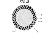
- 1A and 1B are sectional views of such light-reflective conductive particles 10 and 20. First, the light reflective conductive particles in FIG. 1A will be described.
- the light-reflective conductive particles 10 include a core particle 1 coated with a metal material, and titanium oxide (TiO 2 ) particles, boron nitride (BN) particles, zinc oxide (ZnO) particles, and aluminum oxide (Al 2 ) on the surface thereof. And a light reflecting layer 3 formed of at least one kind of inorganic particles 2 selected from the group consisting of O 3 ) particles. Titanium oxide particles, boron nitride particles, zinc oxide particles, or aluminum oxide particles are inorganic particles that exhibit white under sunlight. Accordingly, the light reflecting layer 3 formed from them exhibits white to gray.
- the expression of white to gray means that the wavelength dependency of the reflection characteristic for visible light is small and the visible light is easily reflected.
- titanium oxide particles boron nitride particles, zinc oxide particles or aluminum oxide particles, if there is a concern about photodegradation of the cured product of the cured thermosetting resin composition of anisotropic conductive adhesive, light Zinc oxide which is not catalytic to deterioration and has a high refractive index can be preferably used.
- the core particle 1 Since the core particle 1 is subjected to anisotropic conductive connection, its surface is made of a metal material.
- the surface is coated with a metal material, as described above, an aspect in which the core particle 1 itself is a metal material, or an aspect in which the surface of the resin particle is coated with a metal material can be given.
- the thickness of the light reflecting layer 3 formed from the inorganic particles 2 is too low with respect to the particle size of the core particle 1. If it is too large, poor conduction will occur. Therefore, it is preferably 0.5 to 50%, more preferably 1 to 25%.
- the particle size of the inorganic particles 2 constituting the light-reflecting layer 3 is preferably 0.02 to 4 ⁇ m, more preferably 0.1 to 1 ⁇ m, and particularly preferably 0.2 to 0.5 ⁇ m.
- the particle size of the inorganic particles 2 is set so that the light to be reflected (that is, the light emitted from the light emitting element) is not transmitted. It is preferable that it is 50% or more.
- examples of the shape of the inorganic particles 2 include an amorphous shape, a spherical shape, a scaly shape, and a needle shape.
- a spherical shape is preferable from the viewpoint of the light diffusion effect
- a scaly shape is preferable from the viewpoint of the total reflection effect.
- the light-reflective conductive particles 10 in FIG. 1A are formed by a known film forming technique (so-called mechano-fusion method) in which a film composed of small-sized particles is formed on the surface of large-sized particles by physically colliding large and small powders. ).
- the inorganic particles 2 are fixed so as to bite into the metal material on the surface of the core particle 1, and on the other hand, the inorganic particles monolithically constitute the light reflecting layer 3 because the inorganic particles are not easily fused and fixed together. Therefore, in the case of FIG. 1A, the layer thickness of the light reflecting layer 3 is considered to be equivalent to or slightly thinner than the particle size of the inorganic particles 2.
- the light reflective conductive particles 20 in FIG. 1B will be described.
- the light-reflecting layer 3 contains a thermoplastic resin 4 that functions as an adhesive
- the inorganic particles 2 are also fixed together by this thermoplastic resin 4, and the inorganic particles 2 are multilayered (for example, It differs from the light-reflective conductive particle 10 of FIG. 1A in that it is multi-layered into two or three layers.
- thermoplastic resin 4 By including such a thermoplastic resin 4, the mechanical strength of the light reflecting layer 3 is improved, and the inorganic particles are less likely to be peeled off.
- thermoplastic resin 4 a halogen-free thermoplastic resin can be preferably used for the purpose of low environmental load, and for example, polyolefins such as polyethylene and polypropylene, polystyrene, acrylic resins and the like can be preferably used.
- Such light-reflective conductive particles 20 can also be manufactured by a mechanofusion method. If the particle diameter of the thermoplastic resin 4 applied to the mechano-fusion method is too small, the adhesion function is lowered, and if it is too large, it is difficult to adhere to the core particles, so that it is preferably 0.02 to 4 ⁇ m, more preferably 0.1 ⁇ 1 ⁇ m. Further, if the amount of the thermoplastic resin 4 is too small, the adhesive function is lowered, and if it is too large, aggregates of particles are formed. The amount is 2 to 500 parts by mass, more preferably 4 to 25 parts by mass.
- the blending amount of the conductive particles such as the light-reflective conductive particles in the light-reflective anisotropic conductive adhesive of the present invention is too small, conduction failure tends to occur, and if it is too large, there is a tendency to cause a short circuit between patterns. Therefore, the blending amount of conductive particles such as light-reflective conductive particles with respect to 100 parts by mass of the thermosetting resin composition is preferably 1 to 100 parts by mass, more preferably 10 to 50 parts by mass.
- the light-reflective anisotropic conductive adhesive of the present invention can be produced by uniformly mixing the light-reflective insulating particles, the conductive particles, and the thermosetting resin composition described above according to a conventional method.
- they are dispersed and mixed together with a solvent such as toluene, and applied to the peeled PET film so as to have a desired thickness. What is necessary is just to dry at temperature.
- the reflection characteristic of the light-reflective anisotropic conductive adhesive of the present invention is such that the reflectance of the cured light-reflective anisotropic conductive adhesive to light having a wavelength of 450 nm (JIS) is improved in order to improve the light emission efficiency of the light-emitting element.
- K7105 is at least 30%.
- the reflection characteristics and blending amount of the light-reflective insulating particles to be used, the blending composition of the thermosetting resin composition, and the like may be appropriately adjusted. Usually, if the amount of the light-reflective insulating particles having good reflection characteristics is increased, the reflectance tends to increase.
- the reflection characteristics of the light-reflective anisotropic conductive adhesive can be evaluated from the viewpoint of refractive index. That is, if the refractive index of the cured product is larger than the refractive index of the cured product of the thermosetting resin composition excluding the conductive particles and the light-reflective insulating particles, the light-reflective insulating particles and the thermosetting surrounding them. This is because the amount of light reflection at the interface with the cured product of the conductive resin composition increases.
- the difference obtained by subtracting the refractive index of the cured product of the thermosetting resin composition (JIS K7142) from the refractive index of the light reflective particles (JIS K7142) is preferably 0.02 or more, more preferably It is desired to be 0.2 or more.
- the refractive index of a thermosetting resin composition mainly composed of an epoxy resin is about 1.5.
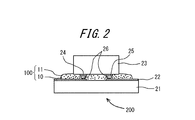
- the light-emitting device 200 includes the connection terminal 22 on the substrate 21 and the connection bumps 26 formed on the n-electrode 24 and the p-electrode 25 of the LED element 23 as light-emitting elements.
- This is a light emitting device in which a light reflective anisotropic conductive adhesive is applied and the substrate 21 and the LED element 23 are flip-chip mounted.
- the light-reflective anisotropic conductive adhesive cured product 100 includes light-reflective insulating particles and conductive particles, preferably the light-reflective conductive particles 10 dispersed in the cured product 11 of the thermosetting resin composition. It will be. In addition, you may seal with transparent mold resin so that the whole LED element 23 may be covered as needed. Moreover, you may provide a light reflection layer in the LED element 23 similarly to the past.
- the light emitting device 200 configured as described above, among the light emitted from the LED elements 23, the light emitted toward the substrate 21 is the light in the cured product 100 of the light-reflective anisotropic conductive adhesive. The light is reflected by the reflective insulating particles or the light-reflective conductive particles 10 and emitted from the upper surface of the LED element 23. Accordingly, it is possible to prevent a decrease in luminous efficiency.
- Configurations other than the light-reflective anisotropic conductive adhesive (the LED element 23, the bump 26, the substrate 21, the connection terminal 22, and the like) in the light-emitting device 200 of the present invention can be the same as the configuration of the conventional light-emitting device. .
- the light emitting device 200 of the present invention can be manufactured by using a conventional anisotropic conductive connection technique except that the light reflective anisotropic conductive adhesive of the present invention is used.
- a well-known light emitting element can be applied in the range which does not impair the effect of this invention other than an LED element.
- a 2% Karstedt platinum catalyst solution (xylene solution) was added to the molten mixture so as to have the following concentration, and the mixture was heated to 140 ° C. with stirring, and the temperature of the molten mixture reached 140 ° C. Then, the temperature was maintained for 6 hours to react 1-allyl-3,5-diglycidyl isocyanurate with 1,3,5,7-tetramethylcyclotetrasiloxane.
- Reference examples 7-8 (Production of side-chain diglycidyl isocyanuryl-modified polysiloxane) In a 1000 mL three-necked flask equipped with a reflux condenser and a magnetic stirrer in a nitrogen stream, 235.21 g (836.25 mmol) of 1-allyl-3,5-diglycidyl isocyanurate (MADGIC, Shikoku Chemical Industry Co., Ltd.) And 125.00 g (442.27 mmol) of 1,1,1,3,5,7,7,7-octamethyltetrasiloxane (manufactured by Tokyo Chemical Industry Co., Ltd.)] Stir at 80 ° C. until uniformly melted.
- MADGIC 1-allyl-3,5-diglycidyl isocyanurate
- MADGIC Shikoku Chemical Industry Co., Ltd.
- 125.00 g (442.27 mmol) of 1,1,1,3,5,7,7,7-octamethyltet
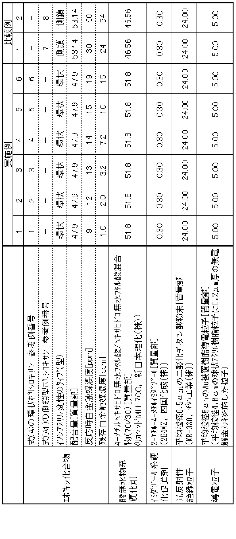
- Examples 1-6, Comparative Examples 1-2 The components of the blending composition shown in Table 2 are blended with an epoxy compound and an acid anhydride curing agent so that the ratio of epoxy group / acid anhydride functional groups is 1 / 1.1, and mixed uniformly. Thus, a light-reflective anisotropic conductive adhesive was prepared.
- the die shear strength of the obtained light-reflective anisotropic conductive adhesive was measured as described below.
- the remaining thermosetting resin composition obtained by removing the light-reflective insulating particles and the conductive particles from the light-reflective anisotropic conductive adhesive was subjected to a heat resistance test and a heat resistance light test as described below. It was. The obtained results are shown in Table 3.
- a glass epoxy board for LED custom product, manufactured by Kansai Electronics Co., Ltd. having a 10 ⁇ m thick silver electrode on which gold bumps (high 10 ⁇ m, diameter 80 ⁇ m, pitch 190 ⁇ m) are formed so that the diameter is 4 mm.
- a light-reflective anisotropic conductive adhesive is applied, and a 0.3 mm square flip chip type LED element (GM35R460G, manufactured by Showa Denko Co., Ltd.) is placed on the glass so that the flip chip type LED element is on the front side.
- the epoxy substrate was placed on a hot plate maintained at 80 ° C. and heated for 2 minutes to temporarily fix the LED element on the glass epoxy substrate for LED.
- the glass epoxy substrate for LED to which this LED element is temporarily fixed, is applied to a thermocompression bonding apparatus and subjected to thermocompression bonding at 230 ° C. for 15 seconds while applying a pressure of 80 gf / chip to the LED element.
- An LED device having LED elements mounted on a substrate was produced.
- the die shear strength (gf / chip) was measured for the LED device thus manufactured. Practically, 200 gf / chip or more was evaluated as good “ ⁇ ”, and less than 200 gf / chip was evaluated as “poor”.
- thermosetting resin composition is sandwiched between two aluminum flat plates (length 100 mm ⁇ width 50.0 mm ⁇ thickness 0.500 mm) with 1 mm height spacers arranged at the four corners, and then heated at 120 ° C. for 30 minutes, and then A cured resin sheet was prepared by heating at 140 ° C. for 1 hour.
- the obtained cured resin sheet was left in an oven set at 150 ° C. for 1000 hours, and spectral characteristics (L * , a * , b * ) before and after being left were measured with a spectrocolorimeter (CM-3600d, Konica Minolta).
- CM-3600d spectrocolorimeter
- the color difference ( ⁇ E) was calculated from the measured values. In practice, ⁇ E of 20 or less was evaluated as very good “ ⁇ ”, 20 to 35 or less was evaluated as“ good ”, and 35 or more was evaluated as defective“ ⁇ ”.
- ⁇ Heat-resistant light test> A cured resin sheet similar to the cured resin sheet subjected to the heat resistance test was prepared, and the cured resin sheet was prepared at a temperature of 120 ° C. with a light intensity of 16 mW / cm 2 (Superwin Mini, Daipura Wintes Co., Ltd.) Made in a metal halide lamp) for 1000 hours, and the resulting cured resin sheet is left in an oven set at 150 ° C.
- the light-reflective anisotropic conductive adhesive of the present invention is used to produce a light-emitting device by flip-chip mounting a light-emitting element such as a light-emitting diode (LED) element on a wiring board using an anisotropic conductive adhesive, Even if a light reflecting layer that causes an increase in manufacturing cost is not provided in the light emitting element, the light emission efficiency can be prevented from being lowered. In addition, the die shear strength can be maintained high, and the heat resistance and heat resistance are excellent. Therefore, the light-reflective anisotropic conductive adhesive of the present invention is useful when the LED element is flip-lip mounted.
- a light-emitting element such as a light-emitting diode (LED) element
Landscapes
- Chemical & Material Sciences (AREA)
- Organic Chemistry (AREA)
- Health & Medical Sciences (AREA)
- Chemical Kinetics & Catalysis (AREA)
- Medicinal Chemistry (AREA)
- Polymers & Plastics (AREA)
- Inorganic Chemistry (AREA)
- Adhesives Or Adhesive Processes (AREA)
- Led Device Packages (AREA)
- Compositions Of Macromolecular Compounds (AREA)
- Epoxy Resins (AREA)
- Electric Connection Of Electric Components To Printed Circuits (AREA)
Abstract
発光ダイオード(LED)素子等の発光素子を配線板に異方性導電接着剤を用いてフリップチップ実装して発光装置を製造する際に、製造コストの増大を招くような光反射層をLED素子に設けなくても、発光効率を改善でき、しかも熱や光により変色しにくい上に実用上十分なダイシェア強度を示す異方性導電接着剤、その接着剤を使用して発光素子を配線板にフリップチップ実装してなる発光装置を提供する。発光装置は、発光素子が配線板に異方性導電接続されている。その異方性導電接続の際に使用する光反射性異方性導電接着剤は、熱硬化性樹脂組成物、導電粒子及び光反射性絶縁粒子を含有する。熱硬化性樹脂組成物は、式(1)で表されるジグリシジルイソシアヌリル変性環状ポリシロキサンと、エポキシ樹脂用硬化剤とを含有する。
Description
本出願は、日本国特許出願2013-253023号(2013年12月6日出願)の優先権を主張するものであり、当該出願の開示全体を、ここに参照のために取り込む。
本発明は、発光素子を配線板に異方性導電接続するために使用する光反射性異方性導電接着剤、その接着剤に含有されるジグリシジルイソシアヌリル変性環状ポリシロキサンを製造するジグリシジルイソシアヌリル変性環状ポリシロキサンの製造方法、及びその接着剤を用いて発光素子を配線板に実装してなる発光装置に関する。
発光ダイオード(LED)素子を使用した発光装置が広く使用されており、旧タイプの発光装置の構造は、図3に示すように、基板31上にダイボンド接着剤32でLED素子33を接合し、その上面のp電極34とn電極35とを、基板31の接続端子36に金ワイヤ37でワイヤボンディングし、LED素子33全体を透明モールド樹脂38で封止したものとなっている。ところが、図3の発光装置の場合、LED素子33が発する光のうち、上面側に出射する400~500nmの波長の光を金ワイヤ37が吸収し、また、下面側に出射した光の一部がダイボンド接着剤32により吸収されてしまい、LED素子33の発光効率が低下するという問題がある。
このため、LED素子の光反射に関する発光効率の向上という観点から、図4に示すように、LED素子33をフリップチップ実装することが提案されている(特許文献1)。このフリップチップ実装技術においては、p電極34とn電極35とにバンプ39がそれぞれ形成されており、更に、LED素子33のバンプ形成面には、p電極34とn電極35と絶縁されるように光反射層40が設けられている。そして、LED素子33と基板31とは、異方性導電ペースト41や異方性導電フィルム(図示せず)を用い、それらを硬化させて接続固定される。このため、図4の発光装置においては、LED素子33の上方への出射した光は金ワイヤで吸収されず、下方へ出射した光の殆どは光反射層40で反射して上方に出射するので、発光効率(光取り出し効率)が低下しない。
また、LED素子の光反射に関する発光効率の向上という観点とは別に、LED素子の実装に用いた異方性導電ペーストや異方性導電フィルム中の絶縁性樹脂成分の熱や光による変色に伴ってLED素子の出射光が色変化してしまうことを防止するという観点から、耐熱性、耐光性に優れた2液硬化型メチルシリコーン樹脂や2液硬化型フェニルシリコーン樹脂を異方性導電ペーストや異方性導電フィルム中の絶縁性樹脂成分に採用することが試みられている。
しかしながら、特許文献1の技術ではLED素子33に光反射層40を、p電極34とn電極35と絶縁するように金属蒸着法などにより設けなければならず、製造上、コストアップが避けられないという問題があり、他方、光反射層40を設けない場合には、硬化した異方性導電ペーストや異方性導電フィルム中の金、ニッケルあるいは銅で被覆された導電粒子の表面は茶色乃至は暗茶色を呈し、また、導電粒子を分散させているエポキシ樹脂バインダー自体も、その硬化のために常用されるイミダゾール系潜在性硬化剤のために茶色を呈しており、発光素子が発した光の発光効率(光取り出し効率)を向上させることが困難であるという問題がある。
また、2液硬化型メチルシリコーン樹脂や2液硬化型フェニルシリコーン樹脂を異方性導電ペーストや異方性導電フィルム中の絶縁性樹脂成分に採用した場合、熱や光による絶縁性樹脂成分の変色は抑制できるものの、実装基板に対するLED素子の剥離強度(ダイシェア強度)が実用に適さないレベルとなってしまうという問題があった。
本発明の目的は、以上の従来の技術の問題点を解決することであり、発光ダイオード(LED)素子等の発光素子を配線板に異方性導電接着剤を用いてフリップチップ実装して発光装置を製造する際に、製造コストの増大を招くような光反射層をLED素子に設けなくても発光効率を改善でき、しかも熱や光により変色しにくい上に実用上十分なダイシェア強度を示す異方性導電接着剤、その接着剤を使用して発光素子を配線板にフリップチップ実装してなる発光装置を提供することである。
本発明者らは、異方性導電接着剤そのものに光反射機能を持たせれば、発光効率を低下させないようにできるとの仮定の下、異方性導電接着剤に、光反射性絶縁粒子を配合することにより、発光素子の発光効率を低下させないようにできることを見出した。また、本発明者らは、異方性導電接着剤の絶縁性接着成分として、特定の構造を有するジグリシジルイソシアヌリル変性環状ポリシロキサンを使用することにより、熱や光により異方性導電接着剤が変色してしまうことを防止でき、しかも実用上十分なダイシェア強度を示すことを見出した。そして、これらの知見に基づき本発明を完成させるに至った。
即ち、本発明は、発光素子を配線板に異方性導電接続するために使用する光反射性異方性導電接着剤であって、熱硬化性樹脂組成物、導電粒子及び光反射性絶縁粒子を含有し、熱硬化性樹脂組成物が、式(1)で表されるジグリシジルイソシアヌリル変性環状ポリシロキサンと、エポキシ樹脂用硬化剤とを含有することを特徴とする光反射性異方性導電接着剤を提供する。

式(1)中、Rはアルキル基又はアリール基であり、nは3~40の整数であり、SiとOとを結ぶ円弧は、ポリシロキサンが環状であることを示している。
また、本発明は、この光反射性異方性導電接着剤の特に好ましい態様として、導電粒子が、金属材料により被覆されているコア粒子と、その表面に酸化チタン粒子、窒化ホウ素、酸化亜鉛粒子及び酸化アルミニウム粒子からなる群より選択される少なくとも一種の無機粒子から形成された光反射層とからなる光反射性導電粒子である光反射性異方性導電接着剤を提供する。
更に、本発明は、式(1)のジグリシジルイソシアヌリル変性環状ポリシロキサンの製造方法であって、式(a)のハイドロジェン環状ポリシロキサンと、式(b)の1-アリル-3,5-ジグリシジルイソシアヌレートとを均一に混合した後、20ppm以下の白金触媒の存在下でハイドロシリレーション反応させることを特徴とする製造方法を提供する。
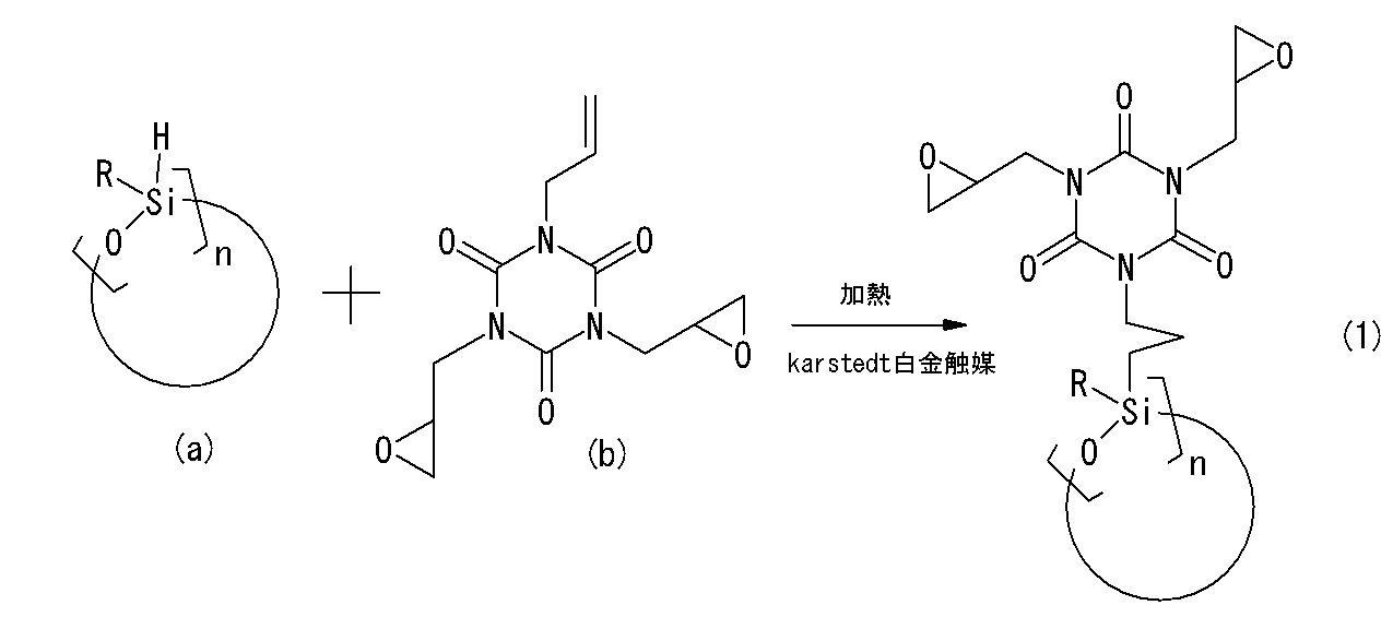
式中、Rはアルキル基又はアリール基であり、nは3~40の整数である。なお、式中のSiとOとを結ぶ円弧は、ポリシロキサンが環状であることを示している。
また、本発明は、上述の光反射性異方性導電接着剤を介して、発光素子をフリップチップ方式で配線板に実装されてなる発光装置を提供する。
発光素子を配線板に異方性導電接続するために使用する本発明の光反射性異方性導電接着剤は、バインダーである熱硬化性樹脂組成物と、光反射性絶縁粒子と、導電粒子とを含有する。この熱硬化性樹脂組成物は、エポキシ樹脂用硬化剤で硬化する式(1)で表されるジグリシジルイソシアヌリル変性環状ポリシロキサンを含有する。この環状ポリシロキサンは、そのポリシロキサン環にジグリシジルイソシアヌリルアルキル基が結合している構造を有する。このような構造のため、理由は明確ではないが、熱や光により異方性導電接着剤が変色してしまうことを防止でき、しかも実用上十分なダイシェア強度を実現することができる。
また、本発明の光反射性異方性導電接着剤は、光反射性絶縁粒子を含有しているため、光を反射することができる。特に、光反射性絶縁粒子が、酸化チタン、窒化ホウ素、酸化亜鉛及び酸化アルミニウムからなる群より選択される少なくとも一種の無機粒子、又は鱗片状もしくは球状金属粒子の表面を絶縁性樹脂で被覆した樹脂被覆金属粒子である場合には、粒子自体がほぼ白色であるため、可視光に対する反射特性の波長依存性が小さく、従って、発光効率を向上させることができ、しかも発光素子の発光色をそのままの色で反射させることができる。
更に、導電粒子として、金属材料で被覆されているコア粒子と、その表面に酸化チタン粒子、窒化ホウ素粒子、酸化亜鉛粒子及び酸化アルミニウム粒子からなる群より選択される少なくとも一種の無機粒子から形成された白色~灰色の光反射層とから構成されている光反射性導電粒子を使用した場合、この光反射性導電粒子自体が白色~灰色を呈しているため、可視光に対する反射特性の波長依存性が小さく、従って、発光効率を更に向上させることができ、しかも発光素子の発光色をそのままの色で反射させることができる。
<<光反射性異方性導電接着剤>>
本発明は、発光素子を配線板に異方性導電接続するために使用する光反射性異方性導電接着剤であって、熱硬化性樹脂組成物、導電粒子及び光反射性絶縁粒子を含有する光反射性異方性導電接着剤である。まず、バインダーである熱硬化性樹脂組成物について説明する。
本発明は、発光素子を配線板に異方性導電接続するために使用する光反射性異方性導電接着剤であって、熱硬化性樹脂組成物、導電粒子及び光反射性絶縁粒子を含有する光反射性異方性導電接着剤である。まず、バインダーである熱硬化性樹脂組成物について説明する。
<熱硬化性樹脂組成物>
(ジグリシジルイソシアヌリル変性環状ポリシロキサン)
本発明において、熱硬化性樹脂組成物は、式(1)で表されるジグリシジルイソシアヌリル変性環状ポリシロキサンと、エポキシ樹脂用硬化剤とを含有する。式(1)で表されるジグリシジルイソシアヌリル変性環状ポリシロキサンを含有することにより、熱や光により異方性導電接着剤が変色してしまうことを防止でき、しかも実用上十分なダイシェア強度を実現することができる。
(ジグリシジルイソシアヌリル変性環状ポリシロキサン)
本発明において、熱硬化性樹脂組成物は、式(1)で表されるジグリシジルイソシアヌリル変性環状ポリシロキサンと、エポキシ樹脂用硬化剤とを含有する。式(1)で表されるジグリシジルイソシアヌリル変性環状ポリシロキサンを含有することにより、熱や光により異方性導電接着剤が変色してしまうことを防止でき、しかも実用上十分なダイシェア強度を実現することができる。

式(1)中、Rは炭素数1~6の低級アルキル基等のアルキル基、又は炭素環式芳香族基、複素環式芳香族等のアリール基である。アルキル基の好ましい具体例としては、メチル基、エチル基、プロピル基、イソプロピル基、ブチル基、イソブチル基を挙げることができ、特に好ましいアルキル基としてはメチル基を挙げることができる。また、アリール基の好ましい具体例としては、フェニル基を挙げることができる。nは3~40の整数であり、好ましくは3~20の整数、より好ましくは4である。
従って、特に好ましい式(1)のジグリシジルイソシアヌリル変性環状ポリシロキサンは、以下の式(A)で表される化合物である。
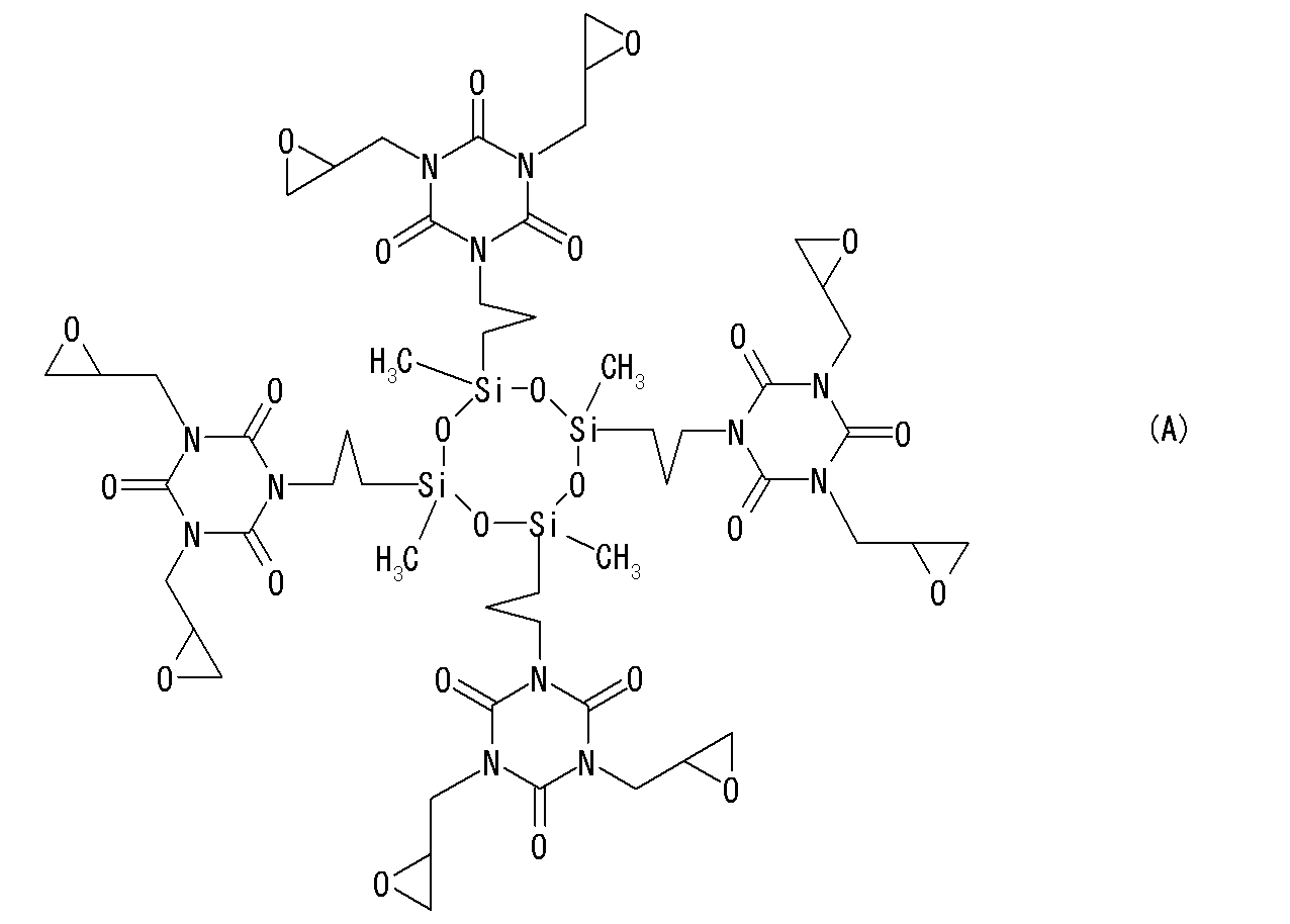
式(1)で表されるジグリシジルイソシアヌリル変性環状ポリシロキサンの熱硬化性樹脂組成物中の含有量は、少なすぎると光反射性異方性導電接着剤の接着性能が低下する傾向があり、多すぎると未硬化エポキシ成分量が過多となる傾向があるので、好ましくは45~65質量%、より好ましくは50~60質量%である。
<ジグリシジルイソシアヌリル変性環状ポリシロキサンの製造方法>
式(1)で表されるジグリシジルイソシアヌリル変性環状ポリシロキサンは、以下の反応式に示すように、式(a)のハイドロジェン環状ポリシロキサンと、式(b)の1-アリル-3,5-ジグリシジルイソシアヌレートとを、窒素などの不活性ガス雰囲気下、適当な溶媒中で、好ましくは無溶媒で均一に混合した後、ハイドロシリル化を触媒可能な白金触媒の存在下で、好ましくは室温~150℃に加熱し、ハイドロシリレーション反応させることにより製造することができる。反応混合物からは、常法(濃縮処理・カラム処理等)により式(1)の化合物を単離することができる。なお、反応式中の置換基は、既に式(1)に関連して説明したとおりである。
式(1)で表されるジグリシジルイソシアヌリル変性環状ポリシロキサンは、以下の反応式に示すように、式(a)のハイドロジェン環状ポリシロキサンと、式(b)の1-アリル-3,5-ジグリシジルイソシアヌレートとを、窒素などの不活性ガス雰囲気下、適当な溶媒中で、好ましくは無溶媒で均一に混合した後、ハイドロシリル化を触媒可能な白金触媒の存在下で、好ましくは室温~150℃に加熱し、ハイドロシリレーション反応させることにより製造することができる。反応混合物からは、常法(濃縮処理・カラム処理等)により式(1)の化合物を単離することができる。なお、反応式中の置換基は、既に式(1)に関連して説明したとおりである。

<白金触媒濃度>
ここで、ハイドロシリレーション反応の際の白金触媒の濃度は、20ppm以下、好ましくは15ppm以下、特に好ましくは10ppm以下である。なお、白金触媒の好ましい下限濃度は、少なくとも1.0ppmである。白金触媒の濃度がこの範囲であれば、ハイドロシリレーション反応をスムーズに進行させ、また、光反射性異方性導電接着剤の熱や光による着色を、接着性を損なわずに抑制することができる。この白金触媒の濃度は、反応開始時点のハイドロジェン環状ポリシロキサンと末端不飽和アルケニル基を有するエポキシ基含有イソシアヌレートとの混合物中の濃度である。具体的には、白金触媒の濃度(Pt)は、ハイドロジェン環状ポリシロキサンや末端不飽和アルケニル基を有するエポキシ基含有イソシアヌレートに対し非常に微量であるため、ハイドロジェン環状ポリシロキサンの質量をW1、末端不飽和アルケニル基を有するエポキシ基含有イソシアヌレートの質量をW2、使用された白金触媒の固形分の質量をW3としたときに、以下の数式で定義される。通常は、“ppm”単位で表現される。
ここで、ハイドロシリレーション反応の際の白金触媒の濃度は、20ppm以下、好ましくは15ppm以下、特に好ましくは10ppm以下である。なお、白金触媒の好ましい下限濃度は、少なくとも1.0ppmである。白金触媒の濃度がこの範囲であれば、ハイドロシリレーション反応をスムーズに進行させ、また、光反射性異方性導電接着剤の熱や光による着色を、接着性を損なわずに抑制することができる。この白金触媒の濃度は、反応開始時点のハイドロジェン環状ポリシロキサンと末端不飽和アルケニル基を有するエポキシ基含有イソシアヌレートとの混合物中の濃度である。具体的には、白金触媒の濃度(Pt)は、ハイドロジェン環状ポリシロキサンや末端不飽和アルケニル基を有するエポキシ基含有イソシアヌレートに対し非常に微量であるため、ハイドロジェン環状ポリシロキサンの質量をW1、末端不飽和アルケニル基を有するエポキシ基含有イソシアヌレートの質量をW2、使用された白金触媒の固形分の質量をW3としたときに、以下の数式で定義される。通常は、“ppm”単位で表現される。

なお、白金触媒は、反応混合物の単離・精製方法などによりエポキシ基含有イソシアヌリル変性環状ポリシロキサン中にも残存してしまう場合があるが、着色の点から、白金触媒残存濃度は、好ましくは20ppm以下、より好ましくは15ppm以下となるようにする。これにより着色のない無色透明な樹脂の取得が可能となる。なお、エポキシ基含有イソシアヌリル変性環状ポリシロキサン中の残存白金触媒濃度は、市販の誘導結合プラズマ発光分析装置)(例えば、Agilent 7500cx ICP-MS、アジレント・テクノロジー(株)製)を用いて測定することができる。
(白金触媒例)
ハイドロシリル化を触媒可能な白金触媒としては、マイナスの電荷を帯びた錯体、0価、2価または4価の白金化合物および白金コロイドが挙げられる。マイナスの電荷を帯びた錯体としては、白金カルボニルクラスターアニオン化合物、例えば、[Pt3(CO)6]2-、[Pt3(CO)6]2 2-、[Pt3(CO)6]4 2-が例示される。0価の白金化合物としては、白金(0)ジビニルテトラメチルジシロキサン錯体、白金(0)テトラビニルテトラメチルシクロテトラシロキサン錯体、白金(0)エチレン錯体、白金(0)スチレン錯体が例示される。2価の白金化合物としては、Pt(II)Cl2,Pt(II)Br2、ビス(エチレン)Pt(II)Cl2、(1,5-シクロオクタジエン)Pt(II)Cl2、白金(II)アセチルアセトナート、ビス(ベンゾニトリル)Pt(II)Cl2が例示される。4価の白金化合物としては、Pt(IV)Cl4、H2Pt(IV)Cl6、Na2Pt(IV)Cl6、K2Pt(IV)Cl6が例示される。中でも、カールステッド(Karstedt)白金触媒(1,3-ジビニル-1,1,3,3-テトラメチルジシロキサン白金(0)錯体)を好ましく使用できる。これらは、必要に応じてキシレンなどの溶媒に溶解させた溶液として使用することができる。
ハイドロシリル化を触媒可能な白金触媒としては、マイナスの電荷を帯びた錯体、0価、2価または4価の白金化合物および白金コロイドが挙げられる。マイナスの電荷を帯びた錯体としては、白金カルボニルクラスターアニオン化合物、例えば、[Pt3(CO)6]2-、[Pt3(CO)6]2 2-、[Pt3(CO)6]4 2-が例示される。0価の白金化合物としては、白金(0)ジビニルテトラメチルジシロキサン錯体、白金(0)テトラビニルテトラメチルシクロテトラシロキサン錯体、白金(0)エチレン錯体、白金(0)スチレン錯体が例示される。2価の白金化合物としては、Pt(II)Cl2,Pt(II)Br2、ビス(エチレン)Pt(II)Cl2、(1,5-シクロオクタジエン)Pt(II)Cl2、白金(II)アセチルアセトナート、ビス(ベンゾニトリル)Pt(II)Cl2が例示される。4価の白金化合物としては、Pt(IV)Cl4、H2Pt(IV)Cl6、Na2Pt(IV)Cl6、K2Pt(IV)Cl6が例示される。中でも、カールステッド(Karstedt)白金触媒(1,3-ジビニル-1,1,3,3-テトラメチルジシロキサン白金(0)錯体)を好ましく使用できる。これらは、必要に応じてキシレンなどの溶媒に溶解させた溶液として使用することができる。
(その他のエポキシ化合物)
熱硬化性樹脂組成物は、式(1)のジグリシジルイソシアヌリル変性環状ポリシロキサンの他に、発明の効果を損なわない範囲で、複素環系エポキシ化合物や脂環式エポキシ化合物や水素添加エポキシ化合物などを含有することができる。
熱硬化性樹脂組成物は、式(1)のジグリシジルイソシアヌリル変性環状ポリシロキサンの他に、発明の効果を損なわない範囲で、複素環系エポキシ化合物や脂環式エポキシ化合物や水素添加エポキシ化合物などを含有することができる。
複素環系エポキシ化合物としては、トリアジン環を有するエポキシ化合物を挙げることができ、例えば、1,3,5-トリス(2,3-エポキシプロピル)-1,3,5-トリアジン-2,4,6-(1H,3H,5H)-トリオン(換言すれば、トリグリシジルイソシアヌレート)を挙げることができる。
脂環式エポキシ化合物としては、分子内に2つ以上のエポキシ基を有するものが好ましく挙げられる。これらは液状であっても、固体状であってもよい。中でも、硬化物にLED素子の実装等に適した光透過性を確保でき、速硬化性にも優れている点から、グリシジルヘキサヒドロビスフェノールA、3,4-エポキシシクロヘキセニルメチル-3′,4′-エポキシシクロヘキセンカルボキシレートを好ましく使用することができる。
水素添加エポキシ化合物としては、前述の複素環系エポキシ化合物や脂環式エポキシ化合物の水素添加物や、その他公知の水素添加エポキシ樹脂を使用することができる。
これらの脂環式エポキシ化合物や複素環系エポキシ化合物や水素添加エポキシ化合物は、式(1)のジグリシジルイソシアヌリル変性環状ポリシロキサンに対し、単独で併用してもよいが、2種以上を併用してもよい。また、これらのエポキシ化合物に加えて本発明の効果を損なわない限り、他のエポキシ化合物を併用してもよい。例えば、ビスフェノールA、ビスフェノールF、ビスフェノールS、テトラメチルビスフェノールA、ジアリールビスフェノールA、ハイドロキノン、カテコール、レゾルシン、クレゾール、テトラブロモビスフェノールA、トリヒドロキシビフェニル、ベンゾフェノン、ビスレゾルシノール、ビスフェノールヘキサフルオロアセトン、テトラメチルビスフェノールA、テトラメチルビスフェノールF、トリス(ヒドロキシフェニル)メタン、ビキシレノール、フェノールノボラック、クレゾールノボラックなどの多価フェノールとエピクロルヒドリンとを反応させて得られるグリシジルエーテル;グリセリン、ネオペンチルグリコール、エチレングリコール、プロピレングリコール、チレングリコール、ヘキシレングリコール、ポリエチレングリコール、ポリプロピレングリコールなどの脂肪族多価アルコールとエピクロルヒドリンとを反応させて得られるポリグリシジルエーテル;p-オキシ安息香酸、β-オキシナフトエ酸のようなヒドロキシカルボン酸とエピクロルヒドリンとを反応させて得られるグリシジルエーテルエステル;フタル酸、メチルフタル酸、イソフタル酸、テレフタル酸、テトラハイドロフタル酸、エンドメチレンテトラハイドロフタル酸、エンドメチレンヘキサハイドロフタル酸、トリメリット酸、重合脂肪酸のようなポリカルボン酸から得られるポリグリシジルエステル;アミノフェノール、アミノアルキルフェノールから得られるグリシジルアミノグリシジルエーテル;アミノ安息香酸から得られるグリシジルアミノグリシジルエステル;アニリン、トルイジン、トリブロムアニリン、キシリレンジアミン、ジアミノシクロヘキサン、ビスアミノメチルシクロヘキサン、4,4′-ジアミノジフェニルメタン、4,4′-ジアミノジフェニルスルホンなどから得られるグリシジルアミン;エポキシ化ポリオレフィン等の公知のエポキシ樹脂類が挙げられる。
(エポキシ樹脂用硬化剤)
エポキシ樹脂用硬化剤としては、公知のエポキシ樹脂用硬化剤を使用することができる。例えば、アミン系硬化剤、ポリアミド系硬化剤、酸無水物系硬化剤、イミダゾール系硬化剤、ポリメルカプタン系硬化剤、ポリスルフィド系硬化剤、三フッ化ホウ素-アミン錯体系硬化剤、ジシアンジアミド、有機酸ヒドラジッド等の中から選択して使用することができる。中でも、光透過性、耐熱性等の観点から酸無水物系硬化剤を好ましく使用することができる。
エポキシ樹脂用硬化剤としては、公知のエポキシ樹脂用硬化剤を使用することができる。例えば、アミン系硬化剤、ポリアミド系硬化剤、酸無水物系硬化剤、イミダゾール系硬化剤、ポリメルカプタン系硬化剤、ポリスルフィド系硬化剤、三フッ化ホウ素-アミン錯体系硬化剤、ジシアンジアミド、有機酸ヒドラジッド等の中から選択して使用することができる。中でも、光透過性、耐熱性等の観点から酸無水物系硬化剤を好ましく使用することができる。
酸無水物系硬化剤としては、無水コハク酸、無水フタル酸、無水マレイン酸、無水トリメリット酸、無水ピロメリット酸、ヘキサヒドロ無水フタル酸、3-メチル-ヘキサヒドロ無水フタル酸、4-メチル-ヘキサヒドロ無水フタル酸、あるいは4-メチル-ヘキサヒドロ無水フタル酸とヘキサヒドロ無水フタル酸との混合物、テトラヒドロ無水フタル酸、メチル-テトラヒドロ無水フタル酸、無水ナジック酸、無水メチルナジック酸、ノルボルナン-2,3-ジカルボン酸無水物、メチルノルボルナン-2,3-ジカルボン酸無水物、メチルシクロヘキセンジカルボン酸無水物等を挙げることができる。
酸無水物系硬化剤等のエポキシ樹脂用硬化剤の熱硬化性樹脂組成物中の配合量は、式(1)で表されるジグリシジルイソシアヌリル変性環状ポリシロキサン100質量部に対して、少なすぎると未硬化エポキシ成分量が過多となる傾向があり、多すぎると余剰の硬化剤の影響で被着体材料の腐食が促進される傾向があるので、好ましくは、50~120質量部、より好ましくは60~100質量部である。
熱硬化性樹脂組成物は、硬化反応を円滑に、かつ短時間で完了させるために、公知の硬化促進剤を含有することができる。好ましい硬化促進剤としては、第四級ホスホニウム塩系硬化促進剤やイミダゾール径硬化促進剤が挙げられる。具体的には、第四級ホスホニウムのブロマイド塩(「U-CAT5003」(商標)、サンアプロ(株)製)、2-エチル-4-メチルイミダゾール等を挙げることができる。特に、酸無水物系硬化剤用の硬化促進剤としては、イミダゾール系硬化促進剤を好ましく使用することができる。この場合、イミダゾール系硬化促進剤の添加量は、少なすぎると硬化が不十分となる傾向があり、多すぎると熱・光に対する変色が大きくなる傾向があるので、酸無水物系硬化剤100質量部に対し、イミダゾール系硬化促進剤を好ましくは0.20~2.00質量部、より好ましくは0.60~1.00質量部である。
以上説明した熱硬化性樹脂組成物は、なるべく無色透明なものを使用することが好ましい。異方性導電接着剤中の光反射性導電粒子の光反射効率を低下させず、しかも入射光の光色を変えずに反射させるためである。ここで、無色透明とは、異方性導電接着剤の硬化物が、波長380~780nmの可視光に対して光路長1cmの光透過率(JIS K7105)が80%以上、好ましくは90%以上となることを意味する。
<光反射性絶縁粒子>
本発明の光反射性異方性導電接着剤が含有する光反射性絶縁粒子は、異方性導電接着剤に入射した光を外部に反射するためのものである。
本発明の光反射性異方性導電接着剤が含有する光反射性絶縁粒子は、異方性導電接着剤に入射した光を外部に反射するためのものである。
なお、光反射性を有する粒子には、金属粒子、金属粒子を樹脂被覆した粒子、自然光の下で灰色から白色である金属酸化物、金属窒素化物、金属硫化物等の無機粒子、樹脂コア粒子を無機粒子で被覆した粒子、粒子の材質によらず、その表面に凹凸がある粒子が含まれる。しかし、これらの粒子の中で、本発明で使用できる光反射性絶縁粒子には、絶縁性を示すことが求められている関係上、絶縁被覆されていない金属粒子は含まれない。また、金属酸化物粒子のうち、ITOのように導電性を有するものは使用できない。また、光反射性且つ絶縁性を示す無機粒子であっても、SiO2のように、その屈折率が使用する熱硬化性樹脂組成物の屈折率よりも低いものは使用できない。
このような光反射性絶縁粒子の好ましい具体例としては、酸化チタン(TiO2)、窒化ホウ素(BN)、酸化亜鉛(ZnO)及び酸化アルミニウム(Al2O3)からなる群より選択される少なくとも一種の無機粒子が挙げられる。中でも、高屈折率の点からTiO2を使用することが好ましい。
光反射性絶縁粒子の形状としては、球状、鱗片状、不定形状、針状等でもよいが、反射効率を考慮すると、球状、鱗片状が好ましい。また、その大きさとしては、球状である場合、小さすぎると反射率が低くなり、大きすぎると異方性導電接続を阻害する傾向があるので、好ましくは0.02~20μm、より好ましくは0.2~1μmであり、鱗片状である場合には、長径が好ましくは0.1~100μm、より好ましくは1~50μm、短径が好ましくは0.01~10μm、より好ましくは0.1~5μm、厚さが好ましくは0.01~10μm、より好ましくは0.1~5μmである。
無機粒子からなる光反射性絶縁粒子は、その屈折率(JIS K7142)が、好ましくは熱硬化性樹脂組成物の硬化物の屈折率(JIS K7142)よりも大きいこと、より好ましくは少なくとも0.02程度大きいことが好ましい。これは、屈折率差が小さいとそれらの界面での反射効率が低下するからである。
光反射性絶縁粒子としては、以上説明した無機粒子を使用してもよいが、鱗片状又は球状金属粒子の表面を透明な絶縁性樹脂で被覆した樹脂被覆金属粒子を使用してもよい。金属粒子としては、ニッケル、銀、アルミニウム等を挙げることができる。粒子の形状としては、不定形状、球状、鱗片状、針状等を挙げることができるが、中でも、光拡散効果の点から球状、全反射効果の点から鱗片状の形状が好ましい。特に、好ましいものは、光の反射率の点から鱗片状銀粒子である。
光反射性絶縁粒子としての樹脂被覆金属粒子の大きさは、形状によっても異なるが、一般に大きすぎると、異方性導電接続を阻害するおそれがあり、小さすぎると光を反射しにくくなるので、好ましくは球状の場合には粒径0.1~30μm、より好ましくは0.2~10μmであり、鱗片状の場合には、長径が好ましくは0.1~100μm、より好ましくは1~50μmで厚みが好ましくは0.01~10μm、より好ましくは0.1~5μmである。ここで、光反射性絶縁粒子の大きさは、絶縁被覆されている場合には、その絶縁被覆も含めた大きさである。
このような樹脂被覆金属粒子における当該樹脂としては、種々の絶縁性樹脂を使用することができる。機械的強度や透明性等の点からアクリル系樹脂の硬化物を好ましく利用することができる。好ましくは、ベンゾイルパーオキサイド等の有機過酸化物などのラジカル開始剤の存在下で、メタクリル酸メチルとメタクリル酸2-ヒドロキシエチルとをラジカル共重合させた樹脂を挙げることができる。この場合、2,4-トリレンジイソシアネート等のイソシアネート系架橋剤で架橋されていることがより好ましい。また、金属粒子としては、予めシランカップリング剤でγ-グリシドキシ基やビニル基等を金属表面に導入しておくことが好ましい。
このような樹脂被覆金属粒子は、例えば、トルエンなどの溶媒中に金属粒子とシランカップリング剤とを投入し、室温で約1時間撹拌した後、ラジカルモノマーとラジカル重合開始剤と、必要に応じて架橋剤とを投入し、ラジカル重合開始温度に加温しながら撹拌することにより製造することができる。
以上説明した光反射性絶縁粒子の、光反射性異方性導電接着剤中の配合量は、少なすぎると十分な光反射を実現することができず、また多すぎると併用している導電粒子に基づく接続が阻害されるので、光反射性異方性導電接着剤中に光反射性絶縁粒子を好ましくは1~50体積%、より好ましくは5~25体積%で含有している。
<導電粒子>
本発明の光反射性異方性導電接着剤を構成する導電粒子としては、異方性導電接続用の従来の導電粒子において用いられている金属の粒子を利用することができる。例えば、金、ニッケル、銅、銀、半田、パラジウム、アルミニウム、それらの合金、それらの多層化物(例えば、ニッケルメッキ/金フラッシュメッキ物)等を挙げることができる。中でも、金、ニッケル、銅は、導電粒子を茶色としてしまうことから、本発明の効果を他の金属材料よりも享受することができる。
本発明の光反射性異方性導電接着剤を構成する導電粒子としては、異方性導電接続用の従来の導電粒子において用いられている金属の粒子を利用することができる。例えば、金、ニッケル、銅、銀、半田、パラジウム、アルミニウム、それらの合金、それらの多層化物(例えば、ニッケルメッキ/金フラッシュメッキ物)等を挙げることができる。中でも、金、ニッケル、銅は、導電粒子を茶色としてしまうことから、本発明の効果を他の金属材料よりも享受することができる。
また、導電粒子として、樹脂粒子を金属材料で被覆した金属被覆樹脂粒子を使用することができる。このような樹脂粒子としては、スチレン系樹脂粒子、ベンゾグアナミン樹脂粒子、ナイロン樹脂粒子などが挙げられる。樹脂粒子を金属材料で被覆する方法としても従来公知の方法を採用することができ、無電解メッキ法、電解メッキ法等を利用することができる。また、被覆する金属材料の層厚は、良好な接続信頼性を確保するに足る厚さであり、樹脂粒子の粒径や金属の種類にもよるが、通常、0.1~3μmである。
また、樹脂粒子の粒径は、小さすぎると導通不良が生じ、大きすぎるとパターン間ショートが生じる傾向があるので、好ましくは1~20μm、より好ましくは3~10μm、特に好ましくは3~5μmである。この場合、コア粒子1の形状としては球状が好ましいが、フレーク状、ラクビーボール状であってもよい。
好ましい金属被覆樹脂粒子は球状形状であり、その粒径は大きすぎると接続信頼性の低下となるので、好ましくは1~20μm、より好ましくは3~10μmである。
特に、本発明においては、上述したような導電粒子に対し光反射性を付与し、光反射性導電粒子とすることが好ましい。図1A、図1Bは、このような光反射性導電粒子10、20の断面図である。まず、図1Aの光反射性導電粒子から説明する。
光反射性導電粒子10は、金属材料で被覆されているコア粒子1と、その表面に酸化チタン(TiO2)粒子、窒化ホウ素(BN)粒子、酸化亜鉛(ZnO)粒子及び酸化アルミニウム(Al2O3)粒子からなる群より選択される少なくとも一種の無機粒子2から形成された光反射層3とから構成される。酸化チタン粒子、窒化ホウ素粒子、酸化亜鉛粒子又は酸化アルミニウム粒子は、太陽光の下では白色を呈する無機粒子である。従って、それらから形成された光反射層3は白色~灰色を呈する。白色~灰色を呈しているということは、可視光に対する反射特性の波長依存性が小さく、且つ可視光を反射しやすいことを意味する。
なお、酸化チタン粒子、窒化ホウ素粒子、酸化亜鉛粒子又は酸化アルミニウム粒子のうち、硬化した異方性導電接着剤の熱硬化性樹脂組成物の硬化物の光劣化が懸念される場合には、光劣化に対して触媒性がなく、屈折率も高い酸化亜鉛を好ましく使用することができる。
コア粒子1は、異方性導電接続に供されるものであるので、その表面が金属材料で構成されている。ここで、表面が金属材料で被覆されている態様としては、前述したように、コア粒子1そのものが金属材料である態様、もしくは樹脂粒子の表面が金属材料で被覆された態様が挙げられる。
無機粒子2から形成された光反射層3の層厚は、コア粒子1の粒径との相対的大きさの観点からみると、コア粒子1の粒径に対し、小さすぎると反射率の低下が著しくなり、大きすぎると導通不良が生ずるので、好ましくは0.5~50%、より好ましくは1~25%である。
また、光反射性導電粒子10において、光反射層3を構成する無機粒子2の粒径は、小さすぎると光反射現象が生じ難くなり、大きすぎると光反射層の形成が困難となる傾向があるので、好ましくは0.02~4μm、より好ましくは0.1~1μm、特に好ましくは0.2~0.5μmである。この場合、光反射させる光の波長の観点からみると、無機粒子2の粒径は、反射させるべき光(即ち、発光素子が発する光)が透過してしまわないように、その光の波長の50%以上であることが好ましい。この場合、無機粒子2の形状としては無定型、球状、鱗片状、針状等を挙げることができるが、中でも、光拡散効果の点から球状、全反射効果の点から鱗片状の形状が好ましい。
図1Aの光反射性導電粒子10は、大小の粉末同士を物理的に衝突させることにより大粒径粒子の表面に小粒径粒子からなる膜を形成させる公知の成膜技術(いわゆるメカノフュージョン法)により製造することができる。この場合、無機粒子2は、コア粒子1の表面の金属材料に食い込むように固定され、他方、無機粒子同士が融着固定されにくいから、無機粒子のモノレイヤーが光反射層3を構成する。従って、図1Aの場合、光反射層3の層厚は、無機粒子2の粒径と同等乃至はわずかに薄くなると考えられる。
次に、図1Bの光反射性導電粒子20について説明する。この光反射性導電粒子20においては、光反射層3が接着剤として機能する熱可塑性樹脂4を含有し、この熱可塑性樹脂4により無機粒子2同士も固定され、無機粒子2が多層化(例えば2層あるいは3層に多層化)している点で、図1Aの光反射性導電粒子10と相違する。このような熱可塑性樹脂4を含有することにより、光反射層3の機械的強度が向上し、無機粒子の剥落などが生じにくくなる。
熱可塑性樹脂4としては、環境低負荷を意図してハロゲンフリーの熱可塑性樹脂を好ましく使用することができ、例えば、ポリエチレン、ポリプロピレン等のポリオレフィンやポリスチレン、アクリル樹脂等を好ましく使用することができる。
このような光反射性導電粒子20も、メカノフュージョン法により製造することができる。メカノフュージョン法に適用する熱可塑性樹脂4の粒子径は、小さすぎると接着機能が低下し、大きすぎるとコア粒子に付着しにくくなるので、好ましくは0.02~4μm、より好ましくは0.1~1μmである。また、このような熱可塑性樹脂4の配合量は、少なすぎると接着機能が低下し、多すぎると粒子の凝集体が形成されるので、無機粒子2の100質量部に対し、好ましくは0.2~500質量部、より好ましくは4~25質量部である。
本発明の光反射性異方性導電接着剤中の光反射性導電粒子等の導電粒子の配合量は、少なすぎると導通不良が生じる傾向があり、多すぎるとパターン間ショートが生ずる傾向があるので、熱硬化性樹脂組成物100質量部に対し、光反射性導電粒子等の導電粒子の配合量は、好ましくは1~100質量部、より好ましくは10~50質量部である。
<光反射性異方性導電接着剤の製造>
本発明の光反射性異方性導電接着剤は、以上説明した光反射性絶縁粒子と導電粒子と熱硬化性樹脂組成物とを、常法に従って均一に混合することにより製造することができる。また、光反射性異方性導電接着フィルムとする場合には、それらをトルエン等の溶媒とともに分散混合し、剥離処理したPETフィルムに所期の厚さとなるように塗布し、約80℃程度の温度で乾燥すればよい。
本発明の光反射性異方性導電接着剤は、以上説明した光反射性絶縁粒子と導電粒子と熱硬化性樹脂組成物とを、常法に従って均一に混合することにより製造することができる。また、光反射性異方性導電接着フィルムとする場合には、それらをトルエン等の溶媒とともに分散混合し、剥離処理したPETフィルムに所期の厚さとなるように塗布し、約80℃程度の温度で乾燥すればよい。
<光反射性異方性導電接着剤の反射特性>
本発明の光反射性異方性導電接着剤の反射特性は、発光素子の発光効率を向上させるために、光反射性異方性導電接着剤の硬化物の波長450nmの光に対する反射率(JIS K7105)が、少なくとも30%であることが望ましい。このような反射率とするためには、使用する光反射性絶縁粒子の反射特性や配合量、熱硬化性樹脂組成物の配合組成などを適宜調整すればよい。通常、反射特性の良好な光反射性絶縁粒子の配合量を増量すれば、反射率も増大する傾向がある。
本発明の光反射性異方性導電接着剤の反射特性は、発光素子の発光効率を向上させるために、光反射性異方性導電接着剤の硬化物の波長450nmの光に対する反射率(JIS K7105)が、少なくとも30%であることが望ましい。このような反射率とするためには、使用する光反射性絶縁粒子の反射特性や配合量、熱硬化性樹脂組成物の配合組成などを適宜調整すればよい。通常、反射特性の良好な光反射性絶縁粒子の配合量を増量すれば、反射率も増大する傾向がある。
また、光反射性異方性導電接着剤の反射特性は屈折率という観点から評価することもできる。即ち、その硬化物の屈折率が、導電粒子と光反射性絶縁粒子とを除いた熱硬化性樹脂組成物の硬化物の屈折率よりも大きいと、光反射性絶縁粒子とそれを取り巻く熱硬化性樹脂組成物の硬化物との界面での光反射量が増大するからである。具体的には、光反射性粒子の屈折率(JIS K7142)から、熱硬化性樹脂組成物の硬化物の屈折率(JIS K7142)を差し引いた差が、好ましくは0.02以上、より好ましくは0.2以上であることが望まれる。なお、通常、エポキシ樹脂を主体とする熱硬化性樹脂組成物の屈折率は約1.5である。
<発光装置>
次に、本発明の発光装置について図2を参照しながら説明する。発光装置200は、基板21上の接続端子22と、発光素子としてLED素子23のn電極24とp電極25とのそれぞれに形成された接続用のバンプ26との間に、前述の本発明の光反射性異方性導電接着剤を塗布し、基板21とLED素子23とがフリップチップ実装されている発光装置である。ここで、光反射性異方性導電接着剤の硬化物100は、光反射性絶縁粒子や導電粒子、好ましくは光反射性導電粒子10が熱硬化性樹脂組成物の硬化物11中に分散してなるものである。なお、必要に応じて、LED素子23の全体を覆うように透明モールド樹脂で封止してもよい。また、LED素子23に従来と同様に光反射層を設けてもよい。
次に、本発明の発光装置について図2を参照しながら説明する。発光装置200は、基板21上の接続端子22と、発光素子としてLED素子23のn電極24とp電極25とのそれぞれに形成された接続用のバンプ26との間に、前述の本発明の光反射性異方性導電接着剤を塗布し、基板21とLED素子23とがフリップチップ実装されている発光装置である。ここで、光反射性異方性導電接着剤の硬化物100は、光反射性絶縁粒子や導電粒子、好ましくは光反射性導電粒子10が熱硬化性樹脂組成物の硬化物11中に分散してなるものである。なお、必要に応じて、LED素子23の全体を覆うように透明モールド樹脂で封止してもよい。また、LED素子23に従来と同様に光反射層を設けてもよい。
このように構成されている発光装置200においては、LED素子23が発した光のうち、基板21側に向かって発した光は、光反射性異方性導電接着剤の硬化物100中の光反射性絶縁粒子や光反射性導電粒子10で反射し、LED素子23の上面から出射する。従って、発光効率の低下を防止することができる。
本発明の発光装置200における光反射性異方性導電接着剤以外の構成(LED素子23、バンプ26、基板21、接続端子22等)は、従来の発光装置の構成と同様とすることができる。また、本発明の発光装置200は、本発明の光反射性異方性導電接着剤を使用すること以外は、従来の異方性導電接続技術を利用して製造することができる。なお、発光素子としては、LED素子の他、本発明の効果を損なわない範囲で公知の発光素子を適用することができる。
参考例1~6(ジグリシジルイソシアヌリル変性環状ポリシロキサンの製造)
窒素気流中、還流冷却管と磁気撹拌子とを備えた100mL三口フラスコに、29.82g(104.36mmol)の1-アリル-3,5-ジグリシジルイソシアヌレート(MADGIC、四国化成工業(株)製)と、5.11g(21.25mmol)の1,3,5,7-テトラメチルシクロテトラシロキサン(Gelest Inc.製)とを投入し、混合物を80℃で均一に溶融するまで撹拌した。続いて、この溶融混合物に2%Karstedt白金触媒溶液(キシレン溶液)を以下の濃度となるように添加し、撹拌しながら140℃になるまで加熱し、溶融混合物の温度が140℃に到達してから、その温度を6時間保持して、1-アリル-3,5-ジグリシジルイソシアヌレートと1,3,5,7-テトラメチルシクロテトラシロキサンとを反応させた。
窒素気流中、還流冷却管と磁気撹拌子とを備えた100mL三口フラスコに、29.82g(104.36mmol)の1-アリル-3,5-ジグリシジルイソシアヌレート(MADGIC、四国化成工業(株)製)と、5.11g(21.25mmol)の1,3,5,7-テトラメチルシクロテトラシロキサン(Gelest Inc.製)とを投入し、混合物を80℃で均一に溶融するまで撹拌した。続いて、この溶融混合物に2%Karstedt白金触媒溶液(キシレン溶液)を以下の濃度となるように添加し、撹拌しながら140℃になるまで加熱し、溶融混合物の温度が140℃に到達してから、その温度を6時間保持して、1-アリル-3,5-ジグリシジルイソシアヌレートと1,3,5,7-テトラメチルシクロテトラシロキサンとを反応させた。
反応終了後、反応混合物を冷却し、カラムクロマトグラフィ(坦体:シリカゲル、溶出液;酢酸エチル/ヘキサン混合溶媒)で処理することにより、耐熱性、耐光性に優れ、着色の少ない参考例1の式(A)のジグリシジルイソシアヌリル変性環状ポリシロキサンを得た。同様に参考例2~6の式(A)のジグリシジルイソシアヌリル変性環状ポリシロキサンを得た。
参考例7~8
(側鎖型のジグリシジルイソシアヌリル変性ポリシロキサンの製造)
窒素気流中、還流冷却管と磁気撹拌子とを備えた1000mL三口フラスコに、235.21g(836.25mmol)の1-アリル-3,5-ジグリシジルイソシアヌレート(MADGIC、四国化成工業(株)製)と、125.00g(442.27mmol)の1,1,1,3,5,7,7,7-オクタメチルテトラシロキサン(東京化成工業(株))製]とを投入し、混合物を80℃で均一に溶融するまで撹拌した。続いて、この溶融混合物に2%Karstedt白金触媒溶液(キシレン溶液)を表1の量[μL]で添加し、撹拌しながら140℃になるまで加熱し、溶融混合物の温度が140℃に到達してから、その温度を6時間保持して、1-アリル-3,5-ジグリシジルイソシアヌレートと1,1,1,3,5,7,7,7-オクタメチルテトラシロキサンとを反応させた。なお、反応時の白金触媒濃度の計算値を表1に示す。
(側鎖型のジグリシジルイソシアヌリル変性ポリシロキサンの製造)
窒素気流中、還流冷却管と磁気撹拌子とを備えた1000mL三口フラスコに、235.21g(836.25mmol)の1-アリル-3,5-ジグリシジルイソシアヌレート(MADGIC、四国化成工業(株)製)と、125.00g(442.27mmol)の1,1,1,3,5,7,7,7-オクタメチルテトラシロキサン(東京化成工業(株))製]とを投入し、混合物を80℃で均一に溶融するまで撹拌した。続いて、この溶融混合物に2%Karstedt白金触媒溶液(キシレン溶液)を表1の量[μL]で添加し、撹拌しながら140℃になるまで加熱し、溶融混合物の温度が140℃に到達してから、その温度を6時間保持して、1-アリル-3,5-ジグリシジルイソシアヌレートと1,1,1,3,5,7,7,7-オクタメチルテトラシロキサンとを反応させた。なお、反応時の白金触媒濃度の計算値を表1に示す。
反応終了後、反応混合物を冷却し、カラムクロマトグラフィ(坦体:シリカゲル、溶出液;酢酸エチル/ヘキサン混合溶媒)で処理することにより、参考例1,2の式(A1)で示す側鎖型のジグリシジルイソシアヌリル変性ポリシロキサンを得た。なお、各参考例で得られたジグリシジルイソシアヌリル変性ポリシロキサン中の残存白金触媒濃度を、誘導結合プラズマ発光分析装置(Agilent 7500cx ICP-MS、アジレント・テクノロジー(株)製)を用いて測定した。測定された残存白金触媒濃度も併せて表1に示す。


実施例1~6,比較例1~2
表2に示す配合組成の成分を、エポキシ基/酸無水物の官能基数の比が1/1.1となるように、エポキシ化合物と酸無水物系硬化剤とを配合し、均一に混合することにより光反射性異方性導電接着剤を調製した。
表2に示す配合組成の成分を、エポキシ基/酸無水物の官能基数の比が1/1.1となるように、エポキシ化合物と酸無水物系硬化剤とを配合し、均一に混合することにより光反射性異方性導電接着剤を調製した。
(評価)
得られた光反射性異方性導電接着剤のダイシェア強度を以下に説明するように測定した。また、光反射性異方性導電接着剤から光反射性絶縁粒子と導電粒子とを除いた残りの熱硬化性樹脂組成物について、以下に説明するように、耐熱試験と耐熱光試験とを行った。得られた結果を表3に示す。
得られた光反射性異方性導電接着剤のダイシェア強度を以下に説明するように測定した。また、光反射性異方性導電接着剤から光反射性絶縁粒子と導電粒子とを除いた残りの熱硬化性樹脂組成物について、以下に説明するように、耐熱試験と耐熱光試験とを行った。得られた結果を表3に示す。
<ダイシェア強度試験>
金バンプ(高10μm、径80μm、ピッチ190μm)が形成された10μm厚の銀ベタ電極を有するLED用ガラスエポキシ基板(特注品、関西電子工業(株)製)に、径が4mmとなるように光反射性異方性導電接着剤を塗布し、そこへ0.3mm角のフリップチップ型LED素子(GM35R460G、昭和電工(株)製)を載せ、フリップチップ型LED素子が表側となるようにガラスエポキシ基板を80℃に保持されたホットプレートに置き、2分間加熱してLED素子をLED用ガラスエポキシ基板に仮固定した。このLED素子が仮固定されたLED用ガラスエポキシ基板を熱圧着装置に適用し、LED素子に80gf/chipの圧力を印加しながら230℃で15秒間熱圧着処理を行うことにより、LED用ガラスエポキシ基板にLED素子が実装されたLED装置を作製した。
金バンプ(高10μm、径80μm、ピッチ190μm)が形成された10μm厚の銀ベタ電極を有するLED用ガラスエポキシ基板(特注品、関西電子工業(株)製)に、径が4mmとなるように光反射性異方性導電接着剤を塗布し、そこへ0.3mm角のフリップチップ型LED素子(GM35R460G、昭和電工(株)製)を載せ、フリップチップ型LED素子が表側となるようにガラスエポキシ基板を80℃に保持されたホットプレートに置き、2分間加熱してLED素子をLED用ガラスエポキシ基板に仮固定した。このLED素子が仮固定されたLED用ガラスエポキシ基板を熱圧着装置に適用し、LED素子に80gf/chipの圧力を印加しながら230℃で15秒間熱圧着処理を行うことにより、LED用ガラスエポキシ基板にLED素子が実装されたLED装置を作製した。
このようにして作製したLED装置について、ダイシェア強度(gf/chip)を測定した。実用上、200gf/chip以上を良好「○」と評価し、200gf/chip未満を不良「×」と評価した。
<耐熱試験>
1mm高さのスペーサが四隅に配置された2枚のアルミニウム平板(長100mm×幅50.0mm×厚0.500mm)で熱硬化性樹脂組成物を挟み、まず120℃で30分加熱し、続いて140℃で1時間加熱することにより硬化樹脂シートを作製した。
1mm高さのスペーサが四隅に配置された2枚のアルミニウム平板(長100mm×幅50.0mm×厚0.500mm)で熱硬化性樹脂組成物を挟み、まず120℃で30分加熱し、続いて140℃で1時間加熱することにより硬化樹脂シートを作製した。
得られた硬化樹脂シートを、150℃に設定されたオーブン内に1000時間放置し、放置前後の分光特性(L*、a*、b*)を、分光測色計(CM-3600d、コニカミノルタ(株))を用いて測定し、得られた測定値から色差(ΔE)を算出した。実用上、ΔEが20以下を非常に良好「◎」、20超35以下を良好「○」と評価し、35超を不良「×」と評価した。
<耐熱光試験>
耐熱試験に供した硬化樹脂シートと同様の硬化樹脂シートを作成し、それを、温度120℃で光強度16mW/cm2に設定された熱光試験機(スーパーウインミニ、ダイプラ・ウィンテス(株)製;メタルハライドランプ使用)内に1000時間放置し、得られた硬化樹脂シートを、150℃に設定されたオーブン内に1000時間放置し、外観着色の有無を観察すると共に、放置前後の分光特性(L*、a*、b*)を、分光測色計(CM-3600d、コニカミノルタ(株)製)を用いて測定し、得られた測定値から色差(ΔE)を算出した。実用上、ΔEは30以下であることが望まれる。併せて耐熱光試験後の外観の着色の有無を目視観察し、着色が観察されなかった場合を良好「○」と評価し、観察された場合を不良「×」と評価した。
耐熱試験に供した硬化樹脂シートと同様の硬化樹脂シートを作成し、それを、温度120℃で光強度16mW/cm2に設定された熱光試験機(スーパーウインミニ、ダイプラ・ウィンテス(株)製;メタルハライドランプ使用)内に1000時間放置し、得られた硬化樹脂シートを、150℃に設定されたオーブン内に1000時間放置し、外観着色の有無を観察すると共に、放置前後の分光特性(L*、a*、b*)を、分光測色計(CM-3600d、コニカミノルタ(株)製)を用いて測定し、得られた測定値から色差(ΔE)を算出した。実用上、ΔEは30以下であることが望まれる。併せて耐熱光試験後の外観の着色の有無を目視観察し、着色が観察されなかった場合を良好「○」と評価し、観察された場合を不良「×」と評価した。

表3から解るように、実施例1~6の光反射性異方性導電接着剤は、ダイシェア強度、耐熱試験及び耐熱光試験の結果がいずれも実用上好ましいものであった。
なお、白金触媒濃度と外観着色との関係を評価するために、側鎖型のジグリシジルイソシアヌリル変性ポリシロキサンを用い、ハイドロシリレーション反応時の白金触媒濃度が20ppmを超え、しかも残存白金触媒量が24ppmまたは54ppmであった比較例1及び2の光反射性異方性導電接着剤を作成し評価したところ、耐熱試験結果が不良であり、しかも外観着色してしまい、使用できないものであった。
本発明の光反射性異方性導電接着剤は、発光ダイオード(LED)素子等の発光素子を配線板に異方性導電接着剤を用いてフリップチップ実装して発光装置を製造する際に、製造コストの増大を招くような光反射層を発光素子に設けなくても、発光効率を低下させないようにすることができる。しかも、ダイシェア強度も高く維持でき、耐熱性、耐熱光性にも優れている。よって、本発明の光反射性異方性導電接着剤は、LED素子をフリップリップ実装する際に有用である。
1 コア粒子
2 無機粒子
3 光反射層
4 熱可塑性樹脂
10、20 光反射性導電粒子
11 熱硬化性樹脂組成物の硬化物
21 基板
22 接続端子
23 LED素子
24 n電極
25 p電極
26 バンプ
31 基板
32 ダイボンド接着剤
33 LED素子
34 p電極
35 n電極
36 接続端子
37 金ワイヤ
38 透明モールド樹脂
39 バンプ
40 光反射層
41 異方性導電ペースト
100 光反射性異方性導電接着剤の硬化物
200 発光装置
2 無機粒子
3 光反射層
4 熱可塑性樹脂
10、20 光反射性導電粒子
11 熱硬化性樹脂組成物の硬化物
21 基板
22 接続端子
23 LED素子
24 n電極
25 p電極
26 バンプ
31 基板
32 ダイボンド接着剤
33 LED素子
34 p電極
35 n電極
36 接続端子
37 金ワイヤ
38 透明モールド樹脂
39 バンプ
40 光反射層
41 異方性導電ペースト
100 光反射性異方性導電接着剤の硬化物
200 発光装置
Claims (15)
- 発光素子を配線板に異方性導電接続するために使用する光反射性異方性導電接着剤であって、熱硬化性樹脂組成物、導電粒子及び光反射性絶縁粒子を含有し、
熱硬化性樹脂組成物が、式(1)

で表されるジグリシジルイソシアヌリル変性環状ポリシロキサンと、エポキシ樹脂用硬化剤とを含有することを特徴とする光反射性異方性導電接着剤。 - Rがメチル基であり、nが4である請求項1記載の光反射性異方性導電接着剤。
- 熱硬化性樹脂組成物が、式(1)のジグリシジルイソシアヌリル変性環状ポリシロキサン100質量部に対し、エポキシ樹脂用硬化剤を50~120質量部含有する請求項1又は2記載の光反射性異方性導電接着剤。
- エポキシ樹脂用硬化剤が、酸無水物系硬化剤である請求項1又は2記載の光反射性異方性導電接着剤。
- 熱硬化性樹脂組成物が、更にイミダゾール系硬化促進剤を含有する請求項4記載の光反射性異方性導電接着剤。
- 熱硬化性樹脂組成物が、酸無水物系硬化剤100質量部に対し、イミダゾール系硬化促進剤を0.20~2.00質量部含有する請求項5記載の光反射性異方性導電接着剤。
- 光反射性絶縁粒子が、酸化チタン、窒化ホウ素、酸化亜鉛及び酸化アルミニウムからなる群より選択される少なくとも一種の無機粒子である請求項1又は2記載の光反射性異方性導電接着剤。
- 光反射性絶縁粒子の屈折率(JIS K7142)が、熱硬化性樹脂組成物の硬化物の屈折率(JIS K7142)よりも大きい請求項1又は2記載の光反射性異方性導電接着剤。
- 光反射性絶縁粒子が、鱗片状又は球状金属粒子の表面を絶縁性樹脂で被覆した樹脂被覆金属粒子である請求項1又は2記載の光反射性異方性導電接着剤。
- 光反射性異方性導電接着剤が、光反射性絶縁粒子を1~50体積%で含有している請求項1又は2記載の光反射性異方性導電接着剤。
- 導電粒子が、金属材料で被覆されているコア粒子と、その表面に酸化チタン粒子、窒化ホウ素粒子、酸化亜鉛粒子及び酸化アルミニウム粒子からなる群より選択される少なくとも一種の無機粒子から形成された光反射層とからなる光反射性導電粒子である請求項1又は2記載の光反射性異方性導電接着剤。
- 熱硬化性樹脂組成物100質量部に対する光反射性導電粒子の配合量が、1~100質量部である請求項11記載の光反射性異方性導電接着剤。
- 式(1)のジグリシジルイソシアヌリル変性環状ポリシロキサンの製造方法であって、式(a)のハイドロジェン環状ポリシロキサンと、式(b)の1-アリル-3,5-ジグリシジルイソシアヌレートとを均一に混合した後、20ppm以下の白金触媒の存在下でハイドロシリレーション反応させることを特徴とする製造方法。
- 請求項1又は2記載の光反射性異方性導電接着剤を介して、発光素子をフリップチップ方式で配線板に実装されている発光装置。
- 発光素子が、発光ダイオードである請求項14記載の発光装置。
Applications Claiming Priority (2)
| Application Number | Priority Date | Filing Date | Title |
|---|---|---|---|
| JP2013253023A JP6384046B2 (ja) | 2013-12-06 | 2013-12-06 | 光反射性異方性導電接着剤及び発光装置 |
| JP2013-253023 | 2013-12-06 |
Publications (1)
| Publication Number | Publication Date |
|---|---|
| WO2015083306A1 true WO2015083306A1 (ja) | 2015-06-11 |
Family
ID=53273097
Family Applications (1)
| Application Number | Title | Priority Date | Filing Date |
|---|---|---|---|
| PCT/JP2014/004510 Ceased WO2015083306A1 (ja) | 2013-12-06 | 2014-09-02 | 光反射性異方性導電接着剤、ジグリシジルイソシアヌリル変性環状ポリシロキサンの製造方法、及び発光装置 |
Country Status (3)
| Country | Link |
|---|---|
| JP (1) | JP6384046B2 (ja) |
| TW (1) | TW201522568A (ja) |
| WO (1) | WO2015083306A1 (ja) |
Cited By (1)
| Publication number | Priority date | Publication date | Assignee | Title |
|---|---|---|---|---|
| CN109643743A (zh) * | 2016-06-21 | 2019-04-16 | 天空公司 | 发光二极管封装 |
Families Citing this family (3)
| Publication number | Priority date | Publication date | Assignee | Title |
|---|---|---|---|---|
| CN113881377B (zh) * | 2021-10-18 | 2022-12-20 | 东莞市雄驰电子有限公司 | 一种酸酐可固化有机硅改性环氧树脂灌封胶及其制备方法 |
| CN113789143B (zh) * | 2021-10-18 | 2022-12-27 | 东莞市雄驰电子有限公司 | 一种室温可固化有机硅改性环氧树脂灌封胶及其制备方法 |
| TWI916027B (zh) | 2024-10-25 | 2026-02-21 | 隆達電子股份有限公司 | 封裝結構 |
Citations (6)
| Publication number | Priority date | Publication date | Assignee | Title |
|---|---|---|---|---|
| JP2003261783A (ja) * | 2002-03-08 | 2003-09-19 | Kanegafuchi Chem Ind Co Ltd | 硬化性組成物、電子材料用組成物、半導体装置、および半導体装置の製造方法 |
| WO2003091338A1 (fr) * | 2002-04-26 | 2003-11-06 | Kaneka Corporation | Composition durcissable, produit durcissant, procede de production correspondant et diode emettrice de lumiere scellee avec le produit durcissant |
| JP2009235254A (ja) * | 2008-03-27 | 2009-10-15 | Nippon Steel Chem Co Ltd | エポキシシリコーン樹脂を含む硬化性樹脂組成物 |
| JP2012052029A (ja) * | 2010-09-01 | 2012-03-15 | Shin-Etsu Chemical Co Ltd | ダイボンド剤及び光半導体装置 |
| JP2012207216A (ja) * | 2011-03-16 | 2012-10-25 | Sony Chemical & Information Device Corp | 光反射性異方性導電接着剤及び発光装置 |
| WO2013187390A1 (ja) * | 2012-06-15 | 2013-12-19 | デクセリアルズ株式会社 | 光反射性異方性導電接着剤及び発光装置 |
-
2013
- 2013-12-06 JP JP2013253023A patent/JP6384046B2/ja active Active
-
2014
- 2014-09-02 WO PCT/JP2014/004510 patent/WO2015083306A1/ja not_active Ceased
- 2014-09-30 TW TW103133835A patent/TW201522568A/zh unknown
Patent Citations (6)
| Publication number | Priority date | Publication date | Assignee | Title |
|---|---|---|---|---|
| JP2003261783A (ja) * | 2002-03-08 | 2003-09-19 | Kanegafuchi Chem Ind Co Ltd | 硬化性組成物、電子材料用組成物、半導体装置、および半導体装置の製造方法 |
| WO2003091338A1 (fr) * | 2002-04-26 | 2003-11-06 | Kaneka Corporation | Composition durcissable, produit durcissant, procede de production correspondant et diode emettrice de lumiere scellee avec le produit durcissant |
| JP2009235254A (ja) * | 2008-03-27 | 2009-10-15 | Nippon Steel Chem Co Ltd | エポキシシリコーン樹脂を含む硬化性樹脂組成物 |
| JP2012052029A (ja) * | 2010-09-01 | 2012-03-15 | Shin-Etsu Chemical Co Ltd | ダイボンド剤及び光半導体装置 |
| JP2012207216A (ja) * | 2011-03-16 | 2012-10-25 | Sony Chemical & Information Device Corp | 光反射性異方性導電接着剤及び発光装置 |
| WO2013187390A1 (ja) * | 2012-06-15 | 2013-12-19 | デクセリアルズ株式会社 | 光反射性異方性導電接着剤及び発光装置 |
Cited By (1)
| Publication number | Priority date | Publication date | Assignee | Title |
|---|---|---|---|---|
| CN109643743A (zh) * | 2016-06-21 | 2019-04-16 | 天空公司 | 发光二极管封装 |
Also Published As
| Publication number | Publication date |
|---|---|
| JP2015110696A (ja) | 2015-06-18 |
| JP6384046B2 (ja) | 2018-09-05 |
| TW201522568A (zh) | 2015-06-16 |
Similar Documents
| Publication | Publication Date | Title |
|---|---|---|
| JP5958107B2 (ja) | 光反射性異方性導電接着剤及び発光装置 | |
| JP5888023B2 (ja) | 光反射性異方性導電接着剤及び発光装置 | |
| CN102482553B (zh) | 光反射性各向异性导电粘接剂及发光装置 | |
| CN102934243B (zh) | 光反射性各向异性导电浆料和发光装置 | |
| CN102859673B (zh) | 光反射性各向异性导电粘接剂及发光装置 | |
| JP6003763B2 (ja) | 熱硬化性樹脂組成物、光反射性異方性導電接着剤及び発光装置 | |
| WO2014013984A1 (ja) | 光反射性異方性導電接着剤及び発光装置 | |
| JP6384046B2 (ja) | 光反射性異方性導電接着剤及び発光装置 | |
| JP6115457B2 (ja) | グリシジルイソシアヌリル変性ポリシロキサンの製造方法 | |
| HK1170255B (en) | Light-reflective anisotropic electroconductive adhesive agent and light-emitting device | |
| HK1178320B (en) | Light-reflective anisotropic conductive adhesive agent, and light emitting device |
Legal Events
| Date | Code | Title | Description |
|---|---|---|---|
| 121 | Ep: the epo has been informed by wipo that ep was designated in this application |
Ref document number: 14867474 Country of ref document: EP Kind code of ref document: A1 |
|
| DPE1 | Request for preliminary examination filed after expiration of 19th month from priority date (pct application filed from 20040101) | ||
| NENP | Non-entry into the national phase |
Ref country code: DE |
|
| 122 | Ep: pct application non-entry in european phase |
Ref document number: 14867474 Country of ref document: EP Kind code of ref document: A1 |