WO2015083245A1 - 記録再生装置、及び記録再生方法 - Google Patents
記録再生装置、及び記録再生方法 Download PDFInfo
- Publication number
- WO2015083245A1 WO2015083245A1 PCT/JP2013/082522 JP2013082522W WO2015083245A1 WO 2015083245 A1 WO2015083245 A1 WO 2015083245A1 JP 2013082522 W JP2013082522 W JP 2013082522W WO 2015083245 A1 WO2015083245 A1 WO 2015083245A1
- Authority
- WO
- WIPO (PCT)
- Prior art keywords
- light
- recording
- recording medium
- reference light
- signal light
- Prior art date
- Legal status (The legal status is an assumption and is not a legal conclusion. Google has not performed a legal analysis and makes no representation as to the accuracy of the status listed.)
- Ceased
Links
Images












Classifications
-
- G—PHYSICS
- G03—PHOTOGRAPHY; CINEMATOGRAPHY; ANALOGOUS TECHNIQUES USING WAVES OTHER THAN OPTICAL WAVES; ELECTROGRAPHY; HOLOGRAPHY
- G03H—HOLOGRAPHIC PROCESSES OR APPARATUS
- G03H1/00—Holographic processes or apparatus using light, infrared or ultraviolet waves for obtaining holograms or for obtaining an image from them; Details peculiar thereto
- G03H1/26—Processes or apparatus specially adapted to produce multiple sub- holograms or to obtain images from them, e.g. multicolour technique
-
- G—PHYSICS
- G03—PHOTOGRAPHY; CINEMATOGRAPHY; ANALOGOUS TECHNIQUES USING WAVES OTHER THAN OPTICAL WAVES; ELECTROGRAPHY; HOLOGRAPHY
- G03H—HOLOGRAPHIC PROCESSES OR APPARATUS
- G03H1/00—Holographic processes or apparatus using light, infrared or ultraviolet waves for obtaining holograms or for obtaining an image from them; Details peculiar thereto
- G03H1/04—Processes or apparatus for producing holograms
- G03H1/0486—Improving or monitoring the quality of the record, e.g. by compensating distortions, aberrations
-
- G—PHYSICS
- G11—INFORMATION STORAGE
- G11B—INFORMATION STORAGE BASED ON RELATIVE MOVEMENT BETWEEN RECORD CARRIER AND TRANSDUCER
- G11B7/00—Recording or reproducing by optical means, e.g. recording using a thermal beam of optical radiation by modifying optical properties or the physical structure, reproducing using an optical beam at lower power by sensing optical properties; Record carriers therefor
- G11B7/004—Recording, reproducing or erasing methods; Read, write or erase circuits therefor
- G11B7/0065—Recording, reproducing or erasing by using optical interference patterns, e.g. holograms
-
- G—PHYSICS
- G11—INFORMATION STORAGE
- G11B—INFORMATION STORAGE BASED ON RELATIVE MOVEMENT BETWEEN RECORD CARRIER AND TRANSDUCER
- G11B7/00—Recording or reproducing by optical means, e.g. recording using a thermal beam of optical radiation by modifying optical properties or the physical structure, reproducing using an optical beam at lower power by sensing optical properties; Record carriers therefor
- G11B7/08—Disposition or mounting of heads or light sources relatively to record carriers
- G11B7/085—Disposition or mounting of heads or light sources relatively to record carriers with provision for moving the light beam into, or out of, its operative position or across tracks, otherwise than during the transducing operation, e.g. for adjustment or preliminary positioning or track change or selection
- G11B7/08547—Arrangements for positioning the light beam only without moving the head, e.g. using static electro-optical elements
- G11B7/08564—Arrangements for positioning the light beam only without moving the head, e.g. using static electro-optical elements using galvanomirrors
Definitions
- the present invention relates to a recording / reproducing apparatus and a recording / reproducing method.
- the Blu-ray Disc (TM) standard using a blue-violet semiconductor laser has made it possible to commercialize an optical disc having a recording density of about 50 GB even for consumer use.
- HDD Hard Disk Drive
- a high-density technology using a new method different from the high-density technology by shortening the wavelength and increasing the NA of the objective lens is necessary.
- hologram recording technology that records digital information using holography is attracting attention.
- Hologram recording technology is a method in which signal light having page data information that is two-dimensionally modulated by a spatial light modulator is superimposed on reference light inside the recording medium, and the interference fringe pattern generated at that time is placed in the recording medium. This is a technique for recording information on a recording medium by causing refractive index modulation.
- the hologram recorded in the recording medium acts like a diffraction grating to generate diffracted light.
- This diffracted light is reproduced as the same light including the recorded signal light and phase information.
- the reproduced signal light is detected two-dimensionally at high speed using a photodetector such as a CMOS or CCD.
- a photodetector such as a CMOS or CCD.
- the hologram recording technique enables two-dimensional information to be recorded on an optical recording medium at once by one hologram and further reproduces this information. Since the page data can be overwritten, large-capacity and high-speed information recording / reproduction can be achieved.
- Patent Document 1 describes that “combined output of main laser light and sub laser light is branched and output. One of the combined lights branched and output from the means to perform the input, and for each of the main laser light and the sub laser light in the combined light, the optical axis position is detected at a plurality of positions given optical path length differences, Based on the detection result, the amount of positional deviation of the optical axis positions of the two laser beams is obtained for each of the plurality of positions, and the main laser light input to the combined branch output means based on the amount of optical axis positional deviation And the relative positional relationship between the optical axes of the sub-laser beams and the optical axis angle difference are adjusted.
- Patent Document 1 when the optical system is downsized, it is likely to be affected by disturbance (heat or vibration) due to changes over time, and the optical axis is also likely to shift. Therefore, when the optical axis of the recording / reproducing optical system is adjusted by adjusting the optical axis of the recording / reproducing position controlling optical system using the optical axis of the recording / reproducing optical system as an index, which optical axis is shifted. There is a problem that it will shift.
- an object of the present invention is to detect and adjust the optical axes of the signal light and the reference light as needed, thereby reducing the optical axis deviation that is likely to occur when the hologram drive device, and thus the hologram recording / reproducing optical system, is downsized. It is an object of the present invention to provide a highly reliable recording / reproducing apparatus and recording / reproducing method capable of compensating, reducing the influence of changes over time, and stably performing high-quality hologram recording.
- the present invention it is possible to provide a highly reliable optical information recording / reproducing apparatus and adjustment method capable of reducing the influence of changes over time and stably recording a high-quality hologram.
- the block diagram which shows the example of the optical information recording / reproducing apparatus of a present Example Flow chart showing an example of recording operation of optical information recording / reproducing apparatus Flowchart showing an example of reproduction operation of the optical information recording / reproducing apparatus
- the figure which shows the example of the optical system structure which performs hologram recording with the optical pick-up in a present Example The figure which shows the example of an optical system structure which reproduces a hologram with the optical pick-up of a present Example
- Schematic illustration of an example of mirror bonding Simulation results of interference between signal light and reference light Simulation results showing the degree of overlap between signal light and reference light due to component misalignment Simulation results showing the degree of overlap between the signal light and the reference light due to the angle deviation of the parts The figure which showed typically the mode at the time of the initial assembly of the angle / relative position automatic adjustment mechanism of a present Example.
- the figure which showed typically the mode at the time of the time / time change of the angle / relative position automatic adjustment mechanism of a present Example The figure which showed typically the mode at the time of angle adjustment of the angle / relative position automatic adjustment mechanism of a present Example.
- the figure which showed typically the mode at the time of relative position adjustment of the angle / relative position automatic adjustment mechanism of a present Example The figure which showed the adjustment medium of a present Example typically The figure which showed typically the angle measuring method of the reference light using the two-dimensional sensor of a present Example
- the flowchart which shows the example of the relative position automatic adjustment operation
- FIG. 1 is a block diagram showing a recording / reproducing apparatus for an optical information recording medium for recording and / or reproducing digital information using holography in the present embodiment.
- the optical information recording / reproducing device 10 is connected to an external control device 91 via an input / output control circuit 90.
- the optical information recording / reproducing apparatus 10 receives the information signal to be recorded from the external control device 91 by the input / output control circuit 90.
- the optical information recording / reproducing apparatus 10 transmits the reproduced information signal to the external control apparatus 91 by the input / output control circuit 90.
- the optical information recording / reproducing apparatus 10 includes an optical pickup 11, a reproducing reference light optical system 12, a cure optical system 13, a disk rotation angle detecting optical system 14, and a rotation motor 50.
- the optical information recording medium 1 is rotated.
- the motor 50 can be rotated.
- the optical pickup 11 plays a role of emitting reference light and signal light to the optical information recording medium 1 and recording digital information on the recording medium using holography.
- the optical axis is automatically adjusted according to this embodiment.
- the optical axis automatic adjustment light detection sensor 22 used for light detection is incorporated in the apparatus, and is moved by the controller 89 to the optical axis position in the optical pickup 11 during adjustment. Thereafter, the optical axis automatic adjustment detection sensor 22 detects the light via the optical axis detection correction circuit 21, detects the angle and relative position of the signal light and the reference light, and then the angle and position deviation from the initial assembly.
- the optical axis adjustment is performed by moving the automatic angle adjustment mechanism of the mirror and the automatic position adjustment mechanism of the sub-base by the actuator 20 by the corresponding amount. Details of the optical axis adjustment will be described later.
- the information signal to be recorded is sent to the spatial light modulator in the optical pickup 11 by the controller 89 via the signal generation circuit 86, and the signal light is transmitted by the spatial light modulator. Modulated.
- the reproduction reference light optical system 12 When reproducing the information recorded on the optical information recording medium 1, the reproduction reference light optical system 12 generates a light wave that causes the reference light emitted from the optical pickup 11 to enter the optical information recording medium 1 in the opposite direction to that during recording. Generate by. Reproduction light reproduced by the reproduction reference light is detected by a photodetector (to be described later) in the optical pickup 11, and a signal is reproduced by the signal processing circuit 85.
- the irradiation time of the reference light and the signal light irradiated on the optical information recording medium 1 can be adjusted by controlling the opening / closing time of the shutter in the optical pickup 11 via the shutter control circuit 87 by the controller 89.
- the cure optical system 13 plays a role of generating a light beam used for pre-cure and post-cure of the optical information recording medium 1.
- Precure is a pre-process for irradiating a predetermined light beam in advance before irradiating the desired position with reference light and signal light when recording information at a desired position in the optical information recording medium 1.
- Post-cure is a post-process for irradiating a predetermined light beam after recording information at a desired position in the optical information recording medium 1 so that additional recording cannot be performed at the desired position.
- the disk rotation angle detection optical system 14 is used to detect the rotation angle of the optical information recording medium 1.
- a signal corresponding to the rotation angle is detected by the disk rotation angle detection optical system 14, and a disk rotation motor control circuit is detected by the controller 89 using the detected signal.
- the rotation angle of the optical information recording medium 1 can be controlled via 88.
- a predetermined light source driving current is supplied from the light source driving circuit 82 to the light sources in the optical pickup 11, the cure optical system 13, and the disk rotation angle detection optical system 14, and each light source emits a light beam with a predetermined light quantity. be able to.
- the optical pickup 11, the disc cure optical system 13, and the optical axis automatic adjustment detection sensor 22 are provided with a mechanism capable of sliding the position in the Bragg direction and the Pitch direction of the optical information recording medium 1, and an access control circuit. Position control is performed via 81.
- the recording technology using the principle of angle multiplexing of holography tends to have a very small tolerance for the deviation of the reference beam angle. Therefore, a mechanism for detecting the deviation amount of the reference light angle is provided in the optical pickup 11, a servo control signal is generated by the servo signal generation circuit 83, and the deviation amount is corrected via the servo control circuit 84. Therefore, it is necessary to provide a servo mechanism for the optical information recording / reproducing apparatus 10.
- optical pickup 11, the cure optical system 13, and the disk rotation angle detection optical system 14 may be simplified by combining several optical system configurations or all optical system configurations.
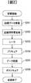
- FIG. 2 shows an operation flow for recording information on the optical information recording medium 1 in the optical information recording / reproducing apparatus 10.
- data to be recorded is received (S201), and information corresponding to the data is sent to the spatial light modulator in the optical pickup 11. Thereafter, various recording learning processes such as power optimization of the light source 101 and exposure time optimization by the shutter 111 are performed in advance so that high-quality information can be recorded on the optical information recording medium (S202). ).
- the access control circuit 81 is controlled to position the optical pickup 11 and the cure optical system 13 at predetermined positions on the optical information recording medium 1.
- the optical information recording medium 1 has address information, it reproduces the address information, checks whether it is positioned at the target position, and calculates the amount of deviation from the predetermined position if it is not positioned at the target position. And repeat the positioning operation.
- a predetermined area is pre-cured using the light beam emitted from the cure optical system 13 (S204), and data is recorded using the reference light and signal light emitted from the pickup 11 (S205).
- post cure is performed using the light beam emitted from the cure optical system 13 (S206). Data may be verified as necessary.
- FIG. 3 shows an operation flow until the information recorded on the optical information recording medium 1 is reproduced by the optical information recording / reproducing apparatus 10.
- the access control circuit 81 is controlled to position the optical pickup 11 and the reproduction reference optical system 12 at predetermined positions on the optical information recording medium 1.
- the optical information recording medium 1 has address information, it reproduces the address information, checks whether it is positioned at the target position, and calculates the amount of deviation from the predetermined position if it is not positioned at the target position. And repeat the positioning operation.
- FIG. 4 is a diagram showing an example of an optical system configuration for performing hologram recording with the optical pickup 11 in the optical information recording / reproducing apparatus 10 of the present embodiment.
- the high-frequency component of the light beam is removed at the hole 104 to obtain a smooth beam profile.
- the light reflected by the mirror 105 and the mirror 106 passes through the high-speed shutter 108 disposed on the focal plane of the relay lens 107.
- the high-speed shutter 108 is used to block light for each angle in synchronization with the movement of the galvanometer mirror 304 during recording.
- the light transmitted through the optical isolator 109 is controlled in its polarization direction by an optical element 110 composed of, for example, a half-wave plate or the like so that the light quantity ratio of p-polarized light and s-polarized light becomes a desired ratio.
- 111 is reflected and enters a PBS (Polarization Beam Splitter) prism 112.
- the light beam transmitted through the PBS prism 112 is referred to as signal light 200.
- the beam diameter is expanded by the beam expander 201, the beam passes through the phase mask 202, the relay lens 203, and the PBS prism 204 and enters the spatial light modulator 205.
- the signal light to which information is added by the spatial light modulator 205 reflects the PBS prism 204 and passes through the relay lens 206 and the polytopic filter 207. Thereafter, the light reflected from the automatic adjusting mirror with actuator 208 is condensed on the optical information recording medium 1 by the objective lens 209 at a predetermined angle.
- the light beam reflected by the PBS prism 112 is referred to as reference light 300.
- reference light 300 transmits through an angle adjusting element 301 in the pitch direction constituted by a wedge prism.
- the light beam diameter of the reference light is controlled to pass through an opening 302 for preventing excessive exposure of the optical information recording medium 1, and enters the galvano mirror 304 through the mirror 303.
- the angle of the galvanometer mirror 304 can be adjusted by an actuator, and the incident angle of the reference light incident on the optical information recording medium 1 after passing through the scanner lens 306 can be set to a desired angle.
- the light reflected by the galvanometer mirror 304 is reflected by the automatic adjustment mirror with actuator 305 and enters the optical information recording medium 1 at a predetermined angle.
- the output angle from the scanner lens 306 is basically determined by the galvanometer mirror 304. However, there is a concern that the output angle may be shifted when an optical axis shift occurs. By controlling 305, it is compensated that the emission angle of the reference light becomes a predetermined value. In order to set the incident angle of the reference light, an element that converts the wavefront of the reference light may be used instead of the galvanometer mirror.
- the signal light and the reference light are incident so as to overlap each other, whereby an interference fringe pattern is formed in the recording medium, and information is written by writing this pattern on the optical information recording medium. Record.
- the incident angle of the reference light incident on the optical information recording medium 1 can be changed by the galvanometer mirror 304, recording by angle multiplexing is possible.
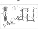
- FIG. 5 is a diagram showing an example of an optical system configuration for performing hologram reproduction with the optical pickup 11 in the optical information recording / reproducing apparatus 10 of the present embodiment.
- the signal light 200 is blocked and only the reference light 300 is made incident on the optical information recording medium 1 through the same optical path as at the time of recording.
- the light beam that has passed through the optical information recording medium 1 passes through an optical element 307 composed of a quarter-wave plate or the like, is then reflected by a galvano mirror 308 whose angle can be adjusted by an actuator, and passes through the optical element 307 again.
- the polarization state changes, and reproduction reference light is generated.
- the reproduction light reproduced by the reference light for reproduction propagates through the objective lens 209, the automatic adjustment mirror with actuator 208, the relay lens 206, and the polytopic filter 207. Thereafter, the light passes through the PBS prism 204 and enters the photodetector 309, and the recorded signal is reproduced.
- the photodetector 309 for example, an image sensor such as a CMOS image sensor or a CCD image sensor can be used, but any element may be used as long as page data can be reproduced.
- optical systems for hologram recording and reproduction in the present embodiment are optical systems for hologram recording and reproduction in the present embodiment, but these are merely examples, and the optical system is not limited to this.
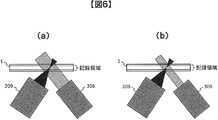
- FIG. 6 is a diagram showing a state in which the signal light emitted from the objective lens 209 and the reference light emitted from the scanner lens 306 interfere with each other in the optical information recording medium 1, and particularly shows an example during initial assembly. Yes.
- the reference light is preferably irradiated by the width of the signal light.
- the optical information recording / reproducing apparatus needs to be downsized depending on the product to be applied.
- downsizing of the apparatus and the optical system is necessary for the convenience of mounting in a rack.
- the fixing method to the holder and the base such as a mirror, a prism, and a lens is a main means instead of screwing.
- expansion and contraction of the adhesive occur due to a temperature change in the optical information recording / reproducing apparatus.
- an adhesive such as an acrylic adhesive or an epoxy adhesive that cures in a short time by irradiating ultraviolet rays is preferable.
- FIG. 7 shows an example of a mirror used in this optical system.
- a 12 mm side mirror is bonded to a holder at four locations, and the adhesive has a size of about ⁇ 1 mm.
- the optical axis deviation ⁇ is generated by 28 mdeg by the mirror 105 in FIG.
- the amount of positional deviation of the optical axis in the optical information recording medium is 1000 (mm) ⁇ tan ⁇ 0.5 (mm).
- FIG. 8A shows an interference state between the signal light 200 and the reference light 300 in the optical information recording medium 1 when there is no component shift and is ideally arranged.
- FIG. 8B shows the result of simulation calculation of the interference state between the signal light 200 and the reference light 300 in the optical information recording medium 1 when the component misalignment occurs by 0.5 mm. From this result, when the component is shifted by 0.5 mm, a place where the reference light does not overlap with the signal light 200 appears in the recording area. That is, the formed hologram becomes weak and the SNR of the reproduced image is deteriorated.
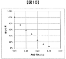
- FIG. 9 and FIG. 10 show the results of calculating the degree of overlap of the signal light 200 and the reference light 300 by simulation when the positional deviation and angular deviation of the scanner lens 306 occur.
- the definition of the overlapping degree is the ratio of the overlapping portion of the reference light to the diameter of the signal light on the lower surface to the upper surface of the recording area.
- a case where the reference light overlaps all the diameters of the irradiated signal light is defined as 100%.
- the purpose of this embodiment is to automatically adjust the optical axis deviation (particularly when the optical system is downsized) caused by changes over time to improve the reliability of recording quality.
- the automatic adjustment method of the present embodiment will be described below with reference to FIG.
- FIG. 11A shows a state where the superposition of the signal light and the reference light is adjusted during the initial assembly.
- the emission angles (in the air) from the objective lens 209 and the scanner lens 306 at this time are defined as ⁇ S0 and ⁇ R0 , respectively. These are equal to the specified angle.
- the signal light and the reference light are overlapped over the upper surface of the lower surface of the recording area.
- the degree of overlap is preferably 100%, but is not limited as long as a desired SNR can be obtained even if it is 100% or less.
- FIG. 11B is a diagram schematically showing an example in which the interference state between the signal light and the reference light changes with time due to heat, vibration, or other causes with respect to the state of FIG.
- the outgoing angles (in the air) from the respective lenses (209, 306) are represented as ⁇ S ′ and ⁇ R ′.
- the present embodiment solves the optical axis deviation by automatic adjustment when the positional deviation and angular deviation of the components occur and the optical axis is displaced as shown in FIG.
- FIG. 11C is a diagram for explaining a method of adjusting the angle between the signal light and the reference light by the automatic adjustment mechanism.
- the adjustment medium 800 is arranged at the same place as when recording and reproducing, and the signal light and the reference light are allowed to pass through.
- the adjustment media may be arranged using the same mechanism as the media actually used for recording.
- the adjustment media arrangement mechanism is retracted to a position in the device that does not overlap the optical axis. You may provide the mechanism which arrange
- the adjustment medium is a medium or a glass plate having the same thickness (cover layer and recording area) and refractive index as the optical information recording medium 1 and is used for adjusting the optical axis.
- the dimensions in the Bragg direction and the Pitch direction orthogonal thereto are assumed to be equal to or larger than the diameters of the signal light and the reference light.
- a two-dimensional sensor 801 for detecting signal light and reference light is stored.
- the two-dimensional sensor 801 is held in a place where light is not irradiated by a retraction mechanism during normal recording / reproduction, and the light is adjusted at the time of optical axis adjustment such as timing at which a change with time seems to have occurred, before recording, or timing at which a light source is turned on.
- the light after passing through the medium is detected in order to determine whether or not the optical axis deviation has occurred.
- the two-dimensional sensor 801 is mounted on an automatic stage capable of adjusting the xyz three-axis position, for example, and is retracted to a place where light is not irradiated during recording and reproduction.
- the configuration is not limited to this.
- the signal light from the objective lens and the reference light from the scanner lens are detected by the two-dimensional sensor 801, and the emission angle (in the air) of each light is measured.
- design angle ⁇ S0 , ⁇ R0 .
- one self-adjusting mirror is provided immediately before the objective lens and the scanner lens, but two or more may be provided.
- the optical axis can be adjusted to the center of the mirror immediately before the lens even when the optical axis is largely deviated, so that there is an advantage that the adjustment margin increases.
- the self-adjusting mirror does not need to be newly added to implement the configuration of this embodiment, and the position of the mirror used to bend the optical axis at another position of the conventional optical system. Can be disposed immediately before the objective lens and the scanner lens, and the cost does not change.
- FIG. 12 shows an example of a schematic diagram of the adjustment medium.
- (A) and (b) show examples of the figure seen from above, and (c) to (g) show examples of sectional views.
- a square shape including a square and a rectangle may be used as shown in (a), or a recording / reproducing medium including a circle may be used as shown in (b).
- an aperture 900 is provided in a part of the adjustment medium.
- the aperture 900 may be on the cover layer of the medium as shown in (c) to (g), in the recording area, or below the cover layer.
- the aperture is used when adjusting the angle of the optical axis, and the aperture diameter ⁇ A is smaller than the diameter ⁇ S of the signal light and the diameter ⁇ R of the reference light ( ⁇ A ⁇ 1 / 2 ⁇ S, ⁇ A ⁇ 1 / 2 ⁇ R). It is used to limit the diameter incident on the two-dimensional sensor.
- the material of the adjusting medium is not limited to glass, and any material may be used as long as the thickness and refractive index are equivalent to those of the optical information recording medium 1. Further, a part of the optical information recording medium 1 that is actually used for recording and reproduction may be used as an unused area, and that part may be used as an adjustment medium. Alternatively, the adjustment medium may not be used at the time of adjustment, and the optical axis position shift amount and the angle shift amount generated by the refractive index of the medium may be converted in consideration later.
- FIG. 13 schematically shows a reference light angle measurement method using a two-dimensional sensor.
- FIG. 14 shows a flow of automatic angle adjustment in the present embodiment.
- the adjustment medium 800 is chucked and moved so that the aperture 900 provided on the medium comes to the recording position (S1401). Then, the position of the medium is adjusted so that the signal light and the reference light pass through the aperture 900 provided in a part of the adjustment medium 800.
- the two-dimensional sensor 801 that has been retracted into the apparatus is placed on the adjustment medium 800 (S1402), the shutter 108 that has blocked the light from the ECLD 101 is opened, and the medium 800 is allowed to pass (S1403). ).
- the emission angle ⁇ S ′ of the signal light 200 is calculated (S1404).
- the emission angle ⁇ S ′ is calculated.
- the same calculation method as that for the signal light 200 is used, and in the same procedure, the output angle ⁇ R ′ is automatically adjusted to be equal to the angle ⁇ R0 adjusted at the time of product shipment (during initial assembly).
- the adjustment mirror 305 is adjusted (S1407 to S1409).
- the angle adjustment is finished.
- the angle adjustment of the signal light 200 is performed first, but the angle adjustment of the reference light 300 may be performed first.
- FIG. 11 (d) schematically shows an example of the relative position adjustment mechanism.
- the relative position adjustment may be performed by moving the signal light side, the reference light side, or both.
- the method of moving the reference light side is the easiest, refer to the embodiment.
- a method for moving the light side will be described. The reason is that since the signal light is convergent light, particularly when it is obliquely incident on the optical information recording medium, the position is changed to the focus position.
- the base 350 is provided with a position adjusting mechanism 802 that can be moved to Bragg and two axes in the Pitch direction orthogonal thereto.
- the position adjustment mechanism 802 is configured by a micrometer, a stepping motor, or the like. It is assumed that the base 350 is held on the main base 351 to which all parts are assembled.
- FIG. 15 schematically shows a method for adjusting the relative positions of signal light and reference light using a two-dimensional sensor.
- FIG. 16 shows a flow of automatic relative position adjustment in the present embodiment.
- the position of the adjusting medium 800 is set so that the position where the aperture 900 of the two-dimensional sensor 801 is not provided comes to the recording position. Move (S1601).
- the adjustment pattern is displayed on the spatial light modulator 205 (S1602).
- the adjustment pattern is preferably close to the number of white and black pixels that are actually recorded, but may be a pattern in which the same number of white and black pixels are present at random. Although it may be all white, there is a possibility that the signal light is actually spread somewhat because there is a concern that the light is collected too much compared to the pattern to be actually recorded.
- the height z of the adjustment medium 800 is changed, and the two-dimensional sensor 801 detects the signal light 200 at the recording area upper surface equivalent position and lower surface equivalent position.
- the reference light 300 is detected by the two-dimensional sensor 801 (S1603).
- a mechanism for blocking the other light may be provided while one of the lights is being detected. For example, when measuring the reference light (to block the signal light), a shutter at the time of reproduction can be used although not shown.
- the relative positions of the irradiation area of the signal light and the reference light on the upper and lower surfaces of the recording area are calculated (S1604).
- the relative positional relationship between the signal light and the reference light stored in advance at the time of initial assembly is compared (S1605).
- the difference ⁇ T 0 T when the coordinates of the ends of the signal light and the reference light on the upper surface of the recording area are (T S0 , T R0 ) and the coordinates (B S0 , B R0 ) on the lower surface in advance during initial assembly.
- the shutter 108 is closed so that the light from the ECLD 101 does not reach the medium (S1608), the two-dimensional sensor 801 is retracted (S1609), and the adjustment medium 800 is removed (S1610). .
- the actual recording optical information recording medium 1 is chucked and recording / reproduction is started.
- the content of adjusting the position of the base 350 on which the scanner lens 306 and the automatic adjustment mirror with actuator 305 are held has been described.
- the objective lens 209 and the automatic adjustment mirror 208 with an actuator may be held on the same base 352 to adjust the position of the base 352, or the reference light side base 350 and Both bases 352 on the signal light side may be adjusted.
- the base (350, 352) may be configured to be held on the main base 351 with a screw, and the screw hole may be opened widely to be used for adjustment.
- the signal in the optical information recording medium 1 necessary for recording / reproduction is required. If the angle and relative position of the light and the reference light do not change from recording to recording and can be kept constant, stable hologram recording is possible. As a result, the SNR is stable and a highly reliable recording / reproducing apparatus can be obtained. Can be provided.
- the two-dimensional sensor 801 described above can use, for example, an image sensor such as a CMOS image sensor or a CCD image sensor, or a PSD (Position Sensitive Detector).
- an image sensor such as a CMOS image sensor or a CCD image sensor
- a PSD Position Sensitive Detector
- the adjustment medium 800 on which the two-dimensional sensor 801 is mounted may be prepared.
- the sensor cable is configured to extend as appropriate.
- the senor is not limited to two dimensions, and may be a sensor such as a photo detector as long as it can detect light.
- the sensor is a two-dimensional sensor, the relative position of the signal light and the reference light can be confirmed by a single detection.
- the sensor position is scanned and detected in the Bragg direction and the Pitch direction. Therefore, there is a difference that it takes some detection time.
- FIG. 17 shows a flow of initial assembly of the optical pickup 11 in the optical information recording / reproducing apparatus 10
- FIG. 18 shows that preparation for recording or reproduction is completed after the optical information recording medium 1 is inserted into the optical information recording / reproducing apparatus 10. The operation flow up to this is shown.
- the optical axes of the common optical path, signal optical path, and reference optical path of the light emitted from the light source are adjusted (S1701).
- the output angle of the signal light from the objective lens is measured, and after confirming that it is equal to the specification angle, the angle is stored (S1702).
- the emission angle of the reference light from the scanner lens is measured and stored in the same manner (S1703).
- the relative positional relationship between the signal light transmitted through the optical information recording medium and the reference light is measured, and after confirming that the reference light overlaps the signal light at a desired ratio, the positional relationship is stored. (S1704).
- the optical axis adjustment at the time of initial assembly is thus completed.
- the optical information recording / reproducing apparatus 10 checks whether the inserted medium is a medium for recording or reproducing digital information using holography, for example. The information recording medium is discriminated (S1802).
- the optical information recording medium is determined to be an optical information recording medium that records or reproduces digital information using holography as a result of discrimination of the optical information recording medium
- the optical information recording / reproducing apparatus 10 controls the control data provided in the optical information recording medium.
- S1803 for example, information on an optical information recording medium and information on various setting conditions during recording and reproduction, for example, are obtained.
- the output angle of the signal light and the reference light is automatically adjusted according to the present embodiment (S1805), and after confirming the coincidence with the angle stored in the initial assembly (S1702, S1703) of FIG. 17, the relative position adjustment is performed.
- Implement (S1806) Similarly, when it is confirmed that the position matches the relative position stored in the initial assembly (S1704) in FIG. 17, the optical information recording / reproducing apparatus 10 is ready for recording or reproduction.
- the automatic angle adjustment (S1805) may be performed only for the reference light, or the automatic relative position adjustment (S1806) may be omitted.
- the interference state between the signal light and the reference light in the optical information recording medium is kept constant even when the optical component arranged in the optical information recording / reproducing apparatus is displaced in position or angle. Can be kept in. Thereby, the recording quality of the hologram can be kept at a certain level, and the reliability of the apparatus can be improved.
- the optical axis adjustment will be required again.
- the interference state of both light beams can be made equal to the previous state, and quick adjustment is possible. Furthermore, by performing this adjustment using the oscillation stabilization waiting time immediately after the ECLD is turned on, the time required to start recording can be shortened, and work efficiency can be improved.
- a present Example is not limited to an above-described Example, Various modifications are included.
- the above-described embodiments have been described in detail for easy understanding of the present invention, and are not necessarily limited to those having all the configurations described.
- a part of the configuration of one embodiment can be replaced with the configuration of another embodiment, and the configuration of another embodiment can be added to the configuration of one embodiment.
- information is recorded by irradiating the optical information recording medium with signal light and reference light to form a hologram, and reproducing information by irradiating the hologram of the optical information recording medium with reference light.
- a recording / reproducing apparatus a laser light source that emits laser light, a branching element that branches the laser light from the laser light source into signal light and reference light, and a space for adding two-dimensional information to the signal light
- an optical information recording / reproducing apparatus comprising a scanner lens for irradiating a reference light to an optical information recording medium, and having at least one mirror in front of the objective lens and the scanner lens.
- the mirror may be a mirror with an actuator.
- the optical information recording / reproducing apparatus is characterized in that the mirror and the scanner lens are held on the same base, and the base includes a position adjusting mechanism.
- the optical information recording / reproducing apparatus is provided with a mechanism for adjusting the relative positional relationship between the objective lens and the scanner lens. There is.
- Modified example 4 is the optical information recording / reproducing apparatus of modified example 1, wherein the signal light base and the reference light base are configured independently of each other, and a mechanism for adjusting the relative positional relationship between them is provided. There is an optical information recording / reproducing apparatus.
- Modified example 4 is the optical information recording / reproducing apparatus of modified example 1, wherein the objective lens and the mirror, the scanner lens and the mirror are respectively held on the same base, and the relative of both bases There is an optical information recording / reproducing apparatus characterized in that a mechanism for adjusting the position is provided.
- a micrometer or a stepping motor may be used as a mechanism for adjusting the position.
- an optical information recording / reproducing apparatus including a light detection sensor, a holding mechanism on the optical axis of the light detection sensor, and a retracting mechanism.
- the light detection sensor may be a two-dimensional sensor or PSD.
- a recording / reproducing method comprising measuring and storing an emission angle of signal light and reference light, Measuring and storing the relative position of the signal light and the reference light in an optical information recording medium;
- an optical information recording / reproducing method comprising an angle adjusting step and a relative position adjusting step, wherein the angle adjusting step is automatically adjusted by an adjusting mirror with an actuator.
- Modified example 7 is the optical information recording / reproducing method of modified example 6, wherein the relative position adjusting step automatically adjusts the position of the scanner lens about two axes.
- the optical information recording / reproducing method according to the sixth modification, wherein the relative position adjusting step adjusts a relative positional relationship between the objective lens and the scanner lens.
- the modification 9 is the optical information recording / reproducing method according to the modification 6, wherein the relative position adjustment step is configured such that the base of the signal light and the base of the reference light are configured independently of each other, and their relative positional relationship
- the relative position adjustment step is configured such that the base of the signal light and the base of the reference light are configured independently of each other, and their relative positional relationship
- the optical information recording / reproducing method in which the relative position adjustment step includes an objective lens and one or more self-adjusting mirrors arranged immediately before, a scanner lens and one 1 arranged immediately before.
- the relative position adjustment step includes an objective lens and one or more self-adjusting mirrors arranged immediately before, a scanner lens and one 1 arranged immediately before.
- the optical information recording / reproducing method further comprising: a light detection step; a step of holding the light detection step on the optical axis; and a step of retracting the light detection step.
- each of the above-described configurations, functions, processing units, processing means, and the like may be realized by hardware by designing a part or all of them with, for example, an integrated circuit.
- Each of the above-described configurations, functions, and the like may be realized by software by interpreting and executing a program that realizes each function by the processor.
- Information such as programs, tables, and files that realize each function can be stored in a memory, a hard disk, a recording device such as an SSD (Solid State Drive), or a recording medium such as an IC card, an SD card, or a DVD.
- SSD Solid State Drive
- control lines and information lines indicate what is considered necessary for the explanation, and not all the control lines and information lines on the product are necessarily shown. Actually, it may be considered that almost all the components are connected to each other.
- Controller 90 ... Input / output control circuit, 91 ... External control device , DESCRIPTION OF SYMBOLS 101 ... Light source, 102 ... Beam shaping element, 103 ... Relay lens, 104 ... Pinhole, 105 ... Mirror, 106 ... Mirror, 107 ... Relay lens, 108 ... High-speed shutter, 109 ... isolator, 110 ... half-wave plate, 111 ... mirror, 112 ... PBS prism, DESCRIPTION OF SYMBOLS 200 ... Signal light, 201 ... Beam expander, 202 ... Phase mask, 203 ... Relay lens, 204 ... PBS prism, 205 ... Spatial light modulator, 206 ...
- Relay Lens 207 ... Polytopic filter, 208 ... Automatic adjustment mirror with actuator, 209 ... Objective lens, 300 ... Reference light, 301 ... Pitch direction angle adjustment element, 302 ... Aperture, 303 ... Mirror, 304 ... Galvano mirror, 305 ... Automatic adjustment mirror with actuator, 306 ..Scanner lens, 307... Quarter wave plate, 308... Rubano mirror, 309... Photodetector, 350.
- 800 Optical axis adjustment medium, 801... Detection sensor for automatic optical axis adjustment, 802... Position adjustment mechanism, 900.
Landscapes
- Physics & Mathematics (AREA)
- General Physics & Mathematics (AREA)
- Optical Recording Or Reproduction (AREA)
- Optical Head (AREA)
Abstract
信号光と参照光の光軸を随時検出して調整することで光軸ずれを補償し、経時変化による影響を低減し安定して高品質のホログラム記録が可能な信頼性の高い記録再生装置および記録再生方法を提供する。 記録媒体に信号光と参照光を照射してホログラムを形成することで情報を記録し、該ホログラムに該参照光を照射することで情報を再生する記録再生装置であって、レーザ光を出射するレーザ光源と、前記レーザ光源からの前記レーザ光を前記信号光と前記参照光に分岐する分岐素子と、前記信号光に2次元情報を付加するための空間光変調部と、角度が可変であり、前記空間光変調部で情報を付加された前記信号光を反射させる第一のミラーと、前記第一のミラーで反射した信号光を、前記記録媒体に照射するための対物レンズと、角度が可変であり、前記分岐素子で分岐された前記参照光を反射させる第二のミラーと、前記第二のミラーで反射した参照光を、前記記録媒体に照射するためのスキャナレンズと、前記対物レンズと前記スキャナレンズの相対位置を調整する位置調整部と、前記第一のミラーと、前記第二のミラーと、前記位置調整部の動作を制御する制御部と、を備える。
Description
本発明は、記録再生装置および記録再生方法に関する。
現在、青紫色半導体レーザを用いた、Blu-ray Disc(TM)規格により、民生用においても50GB程度の記録密度を持つ光ディスクの商品化が可能となってきた。今後は、光ディスクでも100GB~1TBというHDD(Hard Disk Drive)容量と同程度まで大容量化が望まれる。しかしながら、このような超高密度を光ディスクで実現するためには、短波長化と対物レンズの高NA化による高密度化技術とは異なる新しい方式による高密度化技術が必要である。次世代のストレージ技術に関する研究が行われる中、ホログラフィを利用してデジタル情報を記録するホログラム記録技術が注目を集めている。
ホログラム記録技術とは、空間光変調器により二次元的に変調されたページデータの情報を有する信号光を、記録媒体の内部で参照光と重ね合わせ、その時に生じる干渉縞パターンによって記録媒体内に屈折率変調を生じさせることで情報を記録媒体に記録する技術である。
情報の再生時には、記録時に用いた参照光を記録媒体に照射すると、記録媒体中に記録されているホログラムが回折格子のように作用して回折光を生じる。この回折光が記録した信号光と位相情報を含めて同一の光として再生される。再生された信号光は、CMOSやCCDなどの光検出器を用いて二次元的に高速に検出される。このようにホログラム記録技術は、1つのホログラムによって二次元的な情報を一気に光記録媒体に記録し、さらにこの情報を再生することを可能とするものであり、そして、記録媒体のある場所に複数のページデータを重ね書きすることができるため、大容量かつ高速な情報の記録再生を果たすことができる。
ホログラム記録媒体は従来の光ディスクと同様に、トラッキングーサーボなどの記録/再生位置制御を行うことが想定されており、特許文献1には、「メインレーザ光とサブレーザ光との合成光を分岐出力する手段から分岐出力された一方の合成光を入力すると共に、当該合成光内のメインレーザ光とサブレーザ光のそれぞれについて、光路長差が与えられた複数位置でその光軸位置を検出し、その検出結果に基づき、上記複数位置ごとに上記2つのレーザ光の光軸位置の位置ずれ量を求め、それら光軸位置ずれ量に基づいて、上記合成分岐出力手段に対して入力されるメインレーザ光とサブレーザ光の光軸の相対的な位置関係と光軸角度差を調整する。」と記載されている。
しかしながら特許文献1では、特に光学系を小型化した場合、経時変化による外乱(熱や振動)による影響を受けやすくなり、光軸もずれ易いと予想される。したがって、記録/再生用光学系の光軸を指標にして記録/再生位置制御用光学系の光軸を調整すると、記録/再生用光学系の光軸ずれが生じた場合に、どちらの光軸もずれてしまうという課題がある。
そこで本発明の目的は、信号光と参照光の光軸を随時検出して調整することで、ホログラムドライブ装置、ひいてはホログラム記録/再生用の光学系を小型化した場合に生じ易い光軸ずれを補償し、経時変化による影響を低減し安定して高品質のホログラム記録が可能な信頼性の高い記録再生装置および記録再生方法を提供することである。
上記課題は、例えば請求項の範囲に記載の発明により解決される。
本発明によれば、経時変化による影響を低減し、安定して高品質のホログラムの記録が可能な、信頼性の高い光情報記録再生装置および調整方法を提供することが可能となる。
以下、本発明の実施態について図面を用いて説明する。
図1は、本実施例におけるホログラフィを利用してデジタル情報を記録および/または再生する光情報記録媒体の記録再生装置を示すブロック図である。光情報記録再生装置10は、入出力制御回路90を介して外部制御装置91と接続されている。記録する場合には、光情報記録再生装置10は外部制御装置91から記録する情報信号を入出力制御回路90により受信する。再生する場合には、光情報記録再生装置10は再生した情報信号を入出力制御回路90により外部制御装置91に送信する。光情報記録再生装置10は、光ピックアップ11、再生用参照光光学系12、キュア光学系13、ディスク回転角度検出用光学系14、及び回転モータ50を備えており、光情報記録媒体1は回転モータ50によって回転可能な構成となっている。
光ピックアップ11は、参照光と信号光を光情報記録媒体1に出射してホログラフィを利用してデジタル情報を記録媒体に記録する役割を果たす。
記録前に、本実施例による光軸の自動調整を行う。光の検出に使用する光軸自動調整用光検出センサ22は、装置内に組み込まれており、コントローラ89によって調整時に光ピックアップ11内の光軸位置に移動する。その後、光軸自動調整用検出センサ22で光軸検出補正回路21を介して光を検出し、信号光と参照光の角度および相対位置を検出後、初期組立時からの角度と位置のずれ量分だけ、ミラーの自動角度調整機構およびサブベースの自動位置調整機構をアクチュエータ20によって動かして光軸調整を行う。光軸調整の詳細については後述する。
光軸自動調整終了後、ホログラムの記録を行う際、記録する情報信号はコントローラ89によって信号生成回路86を介して光ピックアップ11内の空間光変調器に送り込まれ、信号光は空間光変調器によって変調される。
光情報記録媒体1に記録した情報を再生する場合は、光ピックアップ11から出射された参照光を記録時とは逆の向きに光情報記録媒体1に入射させる光波を再生用参照光光学系12にて生成する。再生用参照光によって再生される再生光を光ピックアップ11内の後述する光検出器によって検出し、信号処理回路85によって信号を再生する。
光情報記録媒体1に照射する参照光と信号光の照射時間は、光ピックアップ11内のシャッタの開閉時間をコントローラ89によってシャッタ制御回路87を介して制御することで調整できる。
キュア光学系13は、光情報記録媒体1のプリキュアおよびポストキュアに用いる光ビームを生成する役割を果たす。プリキュアとは、光情報記録媒体1内の所望の位置に情報を記録する際、所望位置に参照光と信号光を照射する前に予め所定の光ビームを照射する前工程である。ポストキュアとは、光情報記録媒体1内の所望の位置に情報を記録した後、該所望の位置に追記不可能とするために所定の光ビームを照射する後工程である。
ディスク回転角度検出用光学系14は、光情報記録媒体1の回転角度を検出するために用いられる。光情報記録媒体1を所定の回転角度に調整する場合は、ディスク回転角度検出用光学系14によって回転角度に応じた信号を検出し、検出された信号を用いてコントローラ89によってディスク回転モータ制御回路88を介して光情報記録媒体1の回転角度を制御する事が出来る。
光源駆動回路82からは所定の光源駆動電流が光ピックアップ11、キュア光学系13、ディスク回転角度検出用光学系14内の光源に供給され、各々の光源からは所定の光量で光ビームを発光することができる。
また、光ピックアップ11、そして、ディスクキュア光学系13、光軸自動調整用検出センサ22は、光情報記録媒体1のBragg方向、Pitch方向に位置をスライドできる機構が設けられており、アクセス制御回路81を介して位置制御が行われる。
ところで、ホログラフィの角度多重の原理を利用した記録技術は、参照光角度のずれに対する許容誤差が極めて小さくなる傾向がある。したがって、光ピックアップ11内に、参照光角度のずれ量を検出する機構を設けて、サーボ信号生成回路83にてサーボ制御用の信号を生成し、サーボ制御回路84を介して該ずれ量を補正するためのサーボ機構を光情報記録再生装置10内に備えることが必要となる。
また、光ピックアップ11、キュア光学系13、ディスク回転角度検出用光学系14は、いくつかの光学系構成または全ての光学系構成をひとつに纏めて簡素化しても構わない。
図2は、光情報記録再生装置10において光情報記録媒体1に情報を記録する動作フローを示す。
まず、記録するデータを受信して(S201)、該データに応じた情報を光ピックアップ11内の空間光変調器に送り込む。その後、光情報記録媒体に高品質の情報を記録できるように、必要に応じて例えば光源101のパワー最適化やシャッタ111による露光時間の最適化等の各種記録用学習処理を事前に行う(S202)。
その後、シーク動作(S203)ではアクセス制御回路81を制御して、光ピックアップ11ならびにキュア光学系13の位置を光情報記録媒体1の所定の位置に位置づけする。光情報記録媒体1がアドレス情報を持つ場合には、アドレス情報を再生し、目的の位置に位置づけされているか確認し、目的の位置に配置されていなければ、所定の位置とのずれ量を算出し、再度位置づけする動作を繰り返す。その後、キュア光学系13から出射する光ビームを用いて所定の領域をプリキュアし(S204)、ピックアップ11から出射する参照光と信号光を用いてデータを記録する(S205)。
データを記録した後は、キュア光学系13から出射する光ビームを用いてポストキュアを行う(S206)。必要に応じてデータをベリファイしても構わない。
図3は、光情報記録再生装置10において光情報記録媒体1に記録された情報を再生するまでの動作フローを示す。
まず、シーク動作(S301)で、アクセス制御回路81を制御して、光ピックアップ11ならびに再生用参照光光学系12の位置を光情報記録媒体1の所定の位置に位置付けする。光情報記録媒体1がアドレス情報を持つ場合には、アドレス情報を再生し、目的の位置に位置づけされているか確認し、目的の位置に配置されていなければ、所定の位置とのずれ量を算出し、再度位置付けする動作を繰り返す。
その後、光ピックアップ11から参照光を出射し、光情報記録媒体1に記録された情報を読み出し(S302)、再生データを送信する(S303)。
図4は、本実施例の光情報記録再生装置10における光ピックアップ11でホログラム記録を行う光学系構成の一例を示す図である。
光源101である外部共振器付レーザ(External Cavity Laser Diode:ECLD)を出射した光ビームは、ビーム整形素子102を透過して真円形状に整形され、リレーレンズ103の焦点面に配置されたピンホール104で光ビームの高周波成分が除去されてスムースなビームプロファイルを得る。その後ミラー105、ミラー106で反射された光は、リレーレンズ107の焦点面に配置された高速シャッタ108を透過する。高速シャッタ108は、角度多重記録の場合、記録時にガルバノミラー304の動きに同期して角度ごとに光を遮断するために使用する。その後光アイソレータ109を透過した光は、例えば1/2波長板などで構成される光学素子110によってp偏光とs偏光の光量比が所望の比になるように偏光方向が制御された後、ミラー111を反射して、PBS(Polarization Beam Splitter)プリズム112に入射する。
PBSプリズム112を透過した光ビームを信号光200と呼称する。ビームエキスパンダ201によってビーム径が拡大された後、位相マスク202、リレーレンズ203、PBSプリズム204を透過して空間光変調器205に入射する。
空間光変調器205によって情報が付加された信号光は、PBSプリズム204を反射し、リレーレンズ206ならびにポリトピックフィルタ207を透過する。その後、アクチュエータ付自動調整ミラー208を反射した光は、ある所定の角度で対物レンズ209によって光情報記録媒体1に集光する。
一方、PBSプリズム112を反射した光ビームは参照光300と呼称される。例えばウェッジプリズムで構成されるピッチ方向の角度調整用素子301を透過する。その後、参照光の光束径を制御して光情報記録媒体1の余分な露光を防ぐための開口302を通過し、ミラー303を経て、ガルバノミラー304に入射する。ガルバノミラー304はアクチュエータによって角度を調整することができ、スキャナレンズ306を通過した後に光情報記録媒体1に入射する参照光の入射角度を、所望の角度に設定することができる。
ガルバノミラー304を反射した光は、アクチュエータ付自動調整ミラー305で反射され、ある所定の角度で光情報記録媒体1に入射する。スキャナレンズ306からの出射角度を決めるのは基本的にはガルバノミラー304であるが、光軸ずれが発生した場合に出射角度がずれることが懸念されるため、この場合にはアクチュエータ付自動調整ミラー305を制御することで、参照光の出射角度が所定の値となることを補償するものである。なお、参照光の入射角度を設定するために、ガルバノミラーに代えて、参照光の波面を変換する素子を用いても構わない。
このように光情報記録媒体1において、信号光と参照光を互いに重ね合うように入射させることで、記録媒体内には干渉縞パターンが形成され、このパターンを光情報記録媒体に書き込むことで情報を記録する。また、ガルバノミラー304によって光情報記録媒体1に入射する参照光の入射角度を変化させることができるため、角度多重による記録が可能である。
図5は、本実施例の光情報記録再生装置10における光ピックアップ11でホログラム再生を行う光学系構成の一例を示す図である。ホログラムの再生時には、信号光200を遮断し、参照光300のみを記録時と同じ光路で光情報記録媒体1に入射させる。光情報記録媒体1を透過した光ビームは、1/4波長板などで構成される光学素子307を通過した後、アクチュエータによって角度を調整可能なガルバノミラー308で反射され、再び光学素子307を通過することで偏光状態が変わり、再生用参照光が生成される。
この再生用参照光によって再生された再生光は、対物レンズ209、アクチュエータ付自動調整ミラー208、リレーレンズ206ならびにポリトピックフィルタ207を伝播する。その後、PBSプリズム204を透過して光検出器309に入射し、記録した信号が再生される。光検出器309としては例えばCMOSイメージセンサやCCDイメージセンサ等の撮像素子を用いることができるが、ページデータを再生可能であれば、どのような素子であっても構わない。
以上に示した図1、図2が本実施例におけるホログラム記録再生のための光学系であるが、これらは一例であり、光学系はこれに限ったものではない。
図6は、対物レンズ209から出射する信号光と、スキャナレンズ306から出射する参照光が光情報記録媒体1で干渉している状態を示した図であり、特に初期組立時の例を示している。高品質のホログラムを記録するためには、光情報記録媒体の厚さ方向の記録領域すべてに渡って、情報が付加されている信号光に参照光を重ね合わせる必要がある。例えば図6(a)に示すように、参照光の径を信号光に対して大きくすることで、確実に信号光に重ね合わせることができる。
但し、信号光に対して参照光の径が大きすぎると、その分、光情報記録媒体を余分に露光することになり、高密度記録を阻害する要因となる。そこで、図6(b)に示すように、理想的には信号光の幅だけ参照光が照射されることが好ましい。
しかしながら、参照光の径を小さくすることで、部品の位置ずれの観点からは、精度が厳しくなるというデメリットが発生する。
さらに、光情報記録再生装置は、適用される製品によっては小型化が必要となる。例えばアーカイブ装置に適用するためには、ラックに搭載する都合上、装置ひいては光学系の小型化が必要であることが分かっている。光学系の小型化に伴い、ミラーやプリズム、レンズ等のホルダおよびベースへの固定方法は、ねじ止めに替わって、接着が主な手段になると想定される。これにより、光情報記録再生装置内の温度変化によって、接着剤の膨張収縮が起こる。接着剤は、塗布した直後のずれを最小限に抑えるため、アクリル系接着剤もしくはエポキシ系接着剤等、紫外線を照射することにより短時間で硬化するものが好ましい。
図7に、本光学系で使用するミラーの一例を示す。
本装置の応用を想定しているアーカイブ装置の現在の製品仕様は10~50℃であり、温度変化がΔT=40℃発生する。例えば、一辺12mmのミラーをホルダに4箇所接着するものとし、接着剤はφ1mm程度の大きさとする。この場合、温度変化による角度ずれを実測した結果、光軸ずれ量は0.7mdeg/℃となった。従って、温度変化ΔT=40℃のとき、28mdegの光軸ずれが発生することになる。例えば、図1のミラー105によって、光軸ずれΔθが28mdeg発生したとする。この場合、光情報記録媒体1までの距離を1mとすると、光情報記録媒体での光軸の位置ずれ量は、1000(mm)×tanΔθ≒0.5(mm)となる。
図8(a)は、部品ずれが無く、理想的に配置された場合の光情報記録媒体1中の信号光200と参照光300の干渉状態を示す。また、図8(b)に、部品の位置ずれが0.5mm発生した場合の光情報記録媒体1中の信号光200と参照光300の干渉状態をシミュレーションで計算した結果を示す。この結果から、部品が0.5mmずれると記録領域中で参照光が信号光200と重ならない場所が出てくる。すなわち、形成されるホログラムが弱くなり、再生像のSNRが劣化する。
図9、図10に、スキャナレンズ306の位置ずれ、角度ずれが発生したときの信号光200と参照光300の重なり度をシミュレーションで計算した結果を示す。重なり度の定義は、記録領域下面~上面における信号光の径に対する参照光の重なり部の割合である。照射された信号光の径の全てに対して参照光が重なっている場合を100%と定義する。なお、図6(b)に示すように、照射される参照光の径は、信号光の径と略等しくになるように設計するのが望ましい。
この結果から、少しでも部品ずれが発生すると重なり度が大きく減少することが分かる。部品ずれを完全になくすことは困難であるため、部品ずれが生じても、信号光と参照光の重なり度を随時調整して初期組立時と同等に保つことが、安定したホログラム記録を行うために重要である。
上述の説明では、1つの部品の角度ずれが発生した場合を例に挙げたが、ホログラム記録再生光学系では図4に示したように、部品点数が多く、複数の部品がずれることが想定される。さらに接着剤の熱膨張だけでなく、装置の振動等によっても部品ずれが発生する。その結果、信号光と参照光の重なり度が一定に保てなくなり、記録するたびに品質が異なり、高SNRの再生像が得られないという課題が生じる。
そこで本実施例の目的は、経時変化によって生じる光軸ずれ(特に光学系を小型化した場合に影響が大きい)を自動調整し、記録品質の信頼性を向上することである。本実施例の自動調整方法について、図11以降を用いて以下に説明する。
初期組立時、信号光と参照光の重ね合わせを調整した状態が図11(a)である。このときの対物レンズ209、スキャナレンズ306からの出射角度(空気中)をそれぞれθS0、θR0と定義する。これらは仕様角度と等しい。また、光情報記録媒体1中では、記録領域下面上面に渡って、信号光と参照光が重なっている状態である。重なり度は100%が好ましいが、100%以下であっても、所望のSNRが得られるのであれば、この限りではない。
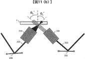
図11(a)の状態に対して、信号光と参照光の干渉状態が、熱または振動その他の原因により経時的に変化した例を模式的に示した図が図11(b)である。それぞれのレンズ(209、306)からの出射角度(空気中)をθS’、θR’と表す。本実施例は、部品の位置ずれ、角度ずれが生じて、図11(b)において示すように光軸がずれた場合に、自動調整によって光軸ずれを解決するものである。
図11(c)は、信号光と参照光の角度を自動調整機構により調整する方法を説明した図である。まず、調整用メディア800を記録再生時と同じ場所に配置し、信号光と参照光を通過させる。調整用メディアは実際に記録に使用するメディアと同様の機構を用いて配置しても良いし、普段は調整用メディア配置機構を装置内の、光軸に重ならない位置に退避させておき、光軸調整時に光軸上に配置するような機構を設けても良い。
また、調整用メディアとは、光情報記録媒体1と厚み(カバー層と記録領域)および屈折率が同等のメディアもしくはガラス板であり、光軸調整時に使用する。Bragg方向およびこれに直交するPitch方向の寸法は、信号光および参照光の径以上であるものとする。
記録再生装置10内には信号光と参照光を検出するための二次元センサ801を格納しておく。二次元センサ801は、通常の記録再生時には退避機構によって光が照射されない場所に保持されており、経時変化が生じたと思われるタイミング、記録前、または光源を点灯したタイミング等の光軸調整時に光軸上に保持され、光軸ずれが発生したか否かを判別するために、メディア通過後の光を検出する。なお二次元センサ801は、例えばxyzの3軸の位置調整が可能な自動ステージに搭載しておき、記録再生時には光が照射されない場所に退避しておくなどの機構を備えるものとする。ただし構成はこの限りではない。
まず、対物レンズからの信号光とスキャナレンズからの参照光を二次元センサ801で検出して、それぞれの光の出射角度(空気中)を測定する。
その後、測定した2光束の出射角度を、あらかじめ記憶しておいた初期組立時(製品出荷時)の角度=設計角度(θS0、θR0)と比較する。角度の差分ΔθS=θS’-θS0、ΔθR=θR’-θR0がそれぞれ0でない場合には、対物レンズとスキャナレンズの直前にそれぞれ設けた、アクチュエータ付の自動調整ミラー208、305の角度を自動調整して、出射角度がそれぞれθS0、θR0になるように調整する。
なお、詳細な測定方法と角度調整方法は図13、14を用いて後程説明する。
本実施例では、自動調整ミラーを対物レンズとスキャナレンズの直前にそれぞれ1枚ずつ設けた場合を説明したが、2枚以上設けても良い。2枚以上設けることで、光軸が大きくずれた場合にも、レンズ直前のミラーの中心に光軸をそれぞれ調整することができるため、調整しろが大きくなるというメリットがある。
また、自動調整ミラーの有効径を大きくすることで、光軸ずれが大きく発生した場合でも、光がミラーから外れずに、調整可能である。また、自動調整ミラーは本実施例の構成を実施するために新たに費用をかけて追加する必要はなく、従来の光学系の別の位置で光軸を折り曲げるために使用していたミラーの位置を、対物レンズとスキャナレンズの直前に配置すれば良いため、コストも変化しない。
図12は、調整用メディアの模式図の例を示す。(a)、(b)は上から見た図の例を、(c)~(g)は断面図の例を示している。(a)に示すように正方形、矩形を含む四角形形状でも良いし、(b)に示すように円形を含む記録再生用の媒体と同形状でも良い。
さらに、調整用メディアの一部分にはアパーチャ900を設ける。アパーチャ900は(c)~(g)に示すようにメディアのカバー層の上でも良いし、記録領域中でも良いし、カバー層の下でも良い。アパーチャは光軸の角度調整時に用いるものであり、アパーチャ径ΦAは、信号光の径ΦS、参照光の径ΦRに対して小さい径であるとし(ΦA≦1/2ΦS、ΦA≦1/2ΦR)、二次元センサに入射する径を制限するために用いる。
調整用メディアの材料は、ガラスに限らず、厚みと屈折率が光情報記録媒体1と同等であれば何でも良い。また、実際に記録再生に用いる光情報記録媒体1の一部を未使用領域とし、その部分を調整用メディアとして使用しても良い。もしくは、調整時に調整用メディアを使わずに、メディアの屈折率分だけ生じる光軸位置ずれ量および角度ずれ量を、後で考慮して換算しても良い。
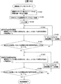
図13、14を用いて、角度測定の詳細な手順について以下に説明する。図13は、二次元センサを用いた参照光の角度測定方法を模式的に示している。図14は、本実施例における角度自動調整のフローを示している。
まず、調整用メディア800をチャッキングし、メディアに設けたアパーチャ900が記録位置へ来るように移動する(S1401)。そして、信号光と参照光が調整用メディア800の一部に設けられたアパーチャ900を透過するようにメディアの位置を調整する。
次に、装置内に退避してあった二次元センサ801を調整用メディア800の上へ配置し(S1402)、ECLD101からの光を遮断していたシャッタ108を開いてメディア800を通過させる(S1403)。
そして、信号光200の出射角度θS’を算出する(S1404)。具体的な算出方法としては、メディアの高さz=z1とz=z2における信号光の位置を二次元センサ801で検出する。高さz=z1とz=z2で検出した信号光の座標をそれぞれx=x1、x=x2とすると、x1、x2の変化量Δxと、z1、z2の変化量Δzを用いて、信号光の出射角度θS’を算出する。 製品出荷時(初期組立時)に調整した信号光角度をθS0としたときに、θS’=θS0となっているかを判定する(S1405)。θS’≠θS0となる場合は、θS’=θS0となるよう、対物レンズ直前の自動調整ミラー208の角度をアクチュエータによって自動調整する(S1406)。その後再び出射角度θS’を測定し、θS’=θS0となるまで繰り返す。
参照光300についても信号光200と同様の算出方法を用いて、同様の手順で、出射角度θR’が製品出荷時(初期組立時)に調整した角度θR0と等しくなるようにアクチュエータ付自動調整ミラー305を調整する(S1407~S1409)。
θS’=θS0、θR’=θR0の条件を両方とも満足したら、角度調整は終了である。なお、図14のフローでは信号光200の角度調整を先に行ったが、参照光300の角度調整を先に行っても構わない。
上述のように、経時変化によって部品の角度ずれのみが発生した場合は、以上の角度調整だけで初期組立時と同じ干渉状態に戻るが、実際は部品の位置ずれと角度ずれが同時に発生することが想定される。そこで次に、信号光と参照光の相対位置の調整を行う。
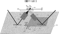
図11(d)に相対位置調整機構の例を模式的に示す。相対位置調整は、信号光側を動かしても、あるいは参照光側を動かしても、あるいは双方を動かして行っても良いが、参照光側を動かす方法が最も容易であるため、実施例では参照光側を動かす方法について説明する。理由は、信号光は収束光であるため、特に光情報記録媒体に斜入射させている場合には、位置を動かすことでフォーカス位置まで変化してしまうためである。
スキャナレンズ306とその直前のアクチュエータ付自動調整ミラー305は同一ベース350上に保持されているものとする。ベース350にはBraggおよびこれに直交するPitch方向の二軸に動かせる位置調整機構802を設けておく。位置調整機構802は、マイクロメータやステッピングモータ等から構成されるものとする。なお、ベース350は全ての部品が組み付いているメインベース351上に保持されているものとする。
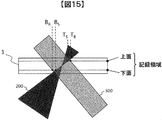
さらに図15、16を用いて、相対位置調整の詳細な手順について以下に説明する。図15は、二次元センサを用いた信号光と参照光の相対位置調整方法を模式的に示している。図16は、本実施例における相対位置自動調整のフローを示している。
相対位置の調整手順としては、まず、信号光200のメディア照射領域を検出するため、調整用メディア800の位置を、二次元センサ801のアパーチャ900が設けられていない位置が記録位置に来るように移動させる(S1601)。
空間光変調器205で調整用パターンを表示する(S1602)。調整用パターンは、実際に記録するデータに白と黒の画素数が近いことが好ましいが、白と黒の画素がランダムに同数程度存在するパターンでも良い。全白でも良いが、実際に記録するパターンに比べて集光されすぎることが懸念されるため、実際は信号光が多少拡がる可能性がある。
次に、調整用メディア800の高さzを変化させ、記録領域上面相当位置、下面相当位置における信号光200を二次元センサ801で検出する。同様に、参照光300を二次元センサ801で検出する(S1603)。この時、2光束を同時にセンサに入射させると照射領域が分かりづらい場合は、片方の光を検出している間は他の光を遮光する機構を設けても良い。例えば参照光を測定する(信号光を遮光したい)場合は、図示はしていないが再生時のシャッタを使用することができる。
以上の測定によって、信号光と参照光の照射領域の、記録領域の上面、下面における相対位置を算出する(S1604)。例えば、図15に示すように、記録領域上面における信号光と参照光の端の座標(TS、TR)および下面における座標(BS、BR)としたときの、それぞれの差分(ΔT=TS-TR、ΔB=BR-BS)を算出する。
その後、あらかじめ初期組立時に記憶しておいた信号光と参照光の相対位置関係と比較する(S1605)。あらかじめ初期組立時に記録領域の上面における信号光と参照光の端の座標を(TS0、TR0)、および、下面における座標(BS0、BR0)としたときのそれぞれの差分ΔT0=TS0-TR0、ΔB0=BR0-BS0、を記憶しておく。そして、調整時のΔT’=TS’-TR’、ΔB’=BR’-BS’の値と比較する。ΔT’=ΔT0、ΔB’=ΔB0でない場合は、上述した、スキャナレンズ306とその手前のアクチュエータ付自動調整ミラー305が保持されているベース350の位置調整機構802の二軸を動かして、ΔT’=ΔT0、ΔB’=ΔB0になるように自動調整する(S1606)。
相対位置の調整が終了したら(S1607)、ECLD101からの光がメディアに届かないようシャッタ108を閉じ(S1608)、二次元センサ801を退避させて(S1609)、調整用メディア800を取り外す(S1610)。そして実際の記録用光情報記録媒体1をチャッキングして記録再生を開始する。
本実施例では、スキャナレンズ306とアクチュエータ付自動調整ミラー305が保持されているベース350の位置を調整する内容を説明した。他の方法として、図示はしないが、対物レンズ209とアクチュエータ付自動調整ミラー208を同一ベース352上に保持してそのベース352の位置を調整しても良いし、あるいは参照光側のベース350および信号光側のベース352双方を調整しても良い。また、例えばベース(350、352)をメインベース351上にねじで保持する構成とし、そのねじ穴を大きく開けておき、調整しろとして使用しても良い。
以上で説明した本実施例によって、経時変化が起きて光源101から光情報記録媒体1までの光路中で光軸ずれが発生した場合でも、記録再生に必要な光情報記録媒体1中での信号光と参照光の角度および相対位置が記録ごとに変化せず、一定の状態を保つことができれば、安定したホログラム記録が可能であり、その結果SNRも安定し、信頼性の高い記録再生装置を提供できる。
上述した二次元センサ801は、例えばCMOSイメージセンサやCCDイメージセンサ等の撮像素子や、PSD(Position Sensitive Detector)を用いることができる。
また、上述したように調整用メディア800とは別に構成されて装置内に格納されていても良いし、あるいは二次元センサ801が搭載された調整用メディア800を用意しても良い。二次元センサを調整用メディアに搭載する場合は、センサのケーブルは適宜伸びる構成であるものとする。
また、センサは二次元に限らず、光を検出できれば良いため、フォトディテクタのようなセンサでも構わない。二次元センサであれば例えば一度の検出で信号光と参照光の相対位置を確認できるが、一次元センサで相対位置を確認するためには、Bragg方向およびPitch方向にセンサ位置をスキャンして検出するため、検出時間を多少要するという違いがある。
図17は、光情報記録再生装置10内の光ピックアップ11の初期組立のフローを示し、図18は光情報記録再生装置10に光情報記録媒体1を挿入した後、記録または再生の準備が完了するまでの動作フローを示したものである。
図17に示すように、初期組立時は、まず光源から出射した光の共通光路、信号光路、参照光路の光軸調整を行う(S1701)。次に対物レンズからの信号光の出射角度を測定し、仕様角度と同等であることを確認後、その角度を記憶しておく(S1702)。次にスキャナレンズからの参照光の出射角度を測定し、同様に記憶しておく(S1703)。最後に、光情報記録媒体を透過した信号光と参照光の相対的な位置関係を測定し、信号光に対して参照光が所望の割合で重なっていることを確認後、位置関係を記憶する(S1704)。以上で初期組立時の光軸調整を終了する。
実際に装置を用いて記録再生を実施する場合について、以下に説明する。図18に示すように、光情報記録媒体を挿入すると(S1801)、光情報記録再生装置10は、例えば挿入された媒体がホログラフィを利用してデジタル情報を記録または再生する媒体であるかどうか光情報記録媒体の判別を行う(S1802)。
光情報記録媒体の判別の結果、ホログラフィを利用してデジタル情報を記録または再生する光情報記録媒体であると判断されると、光情報記録再生装置10は光情報記録媒体に設けられたコントロールデータを読み出し(S1803)、例えば光情報記録媒体に関する情報や、例えば記録や再生時における各種設定条件に関する情報を取得する。
コントロールデータの読み出し後は、コントロールデータに応じた各種調整やピックアップ11に関わる学習処理(S1804)を行う。
次に、本実施例による信号光と参照光の出射角度の自動調整を行い(S1805)、図17の初期組立時(S1702、S1703)で記憶した角度との一致を確認後、相対位置調整を実施する(S1806)。位置についても同様に図17の初期組立時(S1704)で記憶した相対位置と一致することを確認したら、光情報記録再生装置10は、記録または再生の準備が完了する。
例えば光源の点灯直後は、光源内部の温度が安定しないため発振が不安定であり、C.R.(Contrast Ratio)やパワーが変動する。従って、記録再生を開始するまでに、光源が安定するのを30分程度待つ必要がある。光源の安定を待つ時間を利用して、本実施例の自動光軸調整を実施することによって、光軸調整のための余分な時間を使わずに済むというメリットがある。
なお、再生時には信号光は照射しないため、角度自動調整(S1805)は参照光のみについて行っても良いし、相対位置自動調整(S1806)は省略しても良い。
上述した実施例によれば、光情報記録再生装置内に配置される光学部品の位置ずれ、角度ずれが起こった場合にも、光情報記録媒体中での信号光と参照光の干渉状態を一定に保つことができる。これにより、ホログラムの記録品質をある水準に保つことが可能であり、装置の信頼性を向上することができる。また、光源であるECLDやSLMの寿命や故障の際に着脱が必要になった場合に、再度光軸調整が必要となることが予想されるが、その際にも、本実施例によれば両光束の干渉状態が以前と同等になるようにすることができ、かつ素早い調整が可能である。さらに本調整をECLDの点灯直後の発振安定待ちの時間を利用して実施することで、記録を開始するまでの時間を短縮することができ、作業効率を向上することが可能である。
なお、本実施例は上記した実施例に限定されるものではなく、様々な変形例が含まれる。例えば、上記した実施例は本発明を分かりやすく説明するために詳細に説明したものであり、必ずしも説明した全ての構成を備えるものに限定されるものではない。また、ある実施例の構成の一部を他の実施例の構成に置き換えることが可能であり、また、ある実施例の構成に他の実施例の構成を加えることも可能である。また、各実施例の構成の一部について、他の構成の追加・削除・置換をすることが可能である。
具体的な変形例は、以下の通りである。
変形例1として、光情報記録媒体に信号光と参照光を照射してホログラムを形成することで情報を記録し、光情報記録媒体のホログラムに参照光を照射することで情報を再生する光情報記録再生装置であって、レーザ光を出射するレーザ光源と、前記レーザ光源からの前記レーザ光を信号光と参照光に分岐する分岐素子と、前記信号光に2次元情報を付加するための空間光変調部と、光情報記録媒体に信号光を照射するための対物レンズと、
光情報記録媒体に参照光を照射するためのスキャナレンズと、を備え、前記対物レンズとスキャナレンズの直前にそれぞれミラーを1枚以上備えることを特徴とする光情報記録再生装置がある。また、前記ミラーはアクチュエータ付ミラーでも良い。
光情報記録媒体に参照光を照射するためのスキャナレンズと、を備え、前記対物レンズとスキャナレンズの直前にそれぞれミラーを1枚以上備えることを特徴とする光情報記録再生装置がある。また、前記ミラーはアクチュエータ付ミラーでも良い。
変形例2として、変形例1の光情報記録再生装置であって、前記ミラーと前記スキャナレンズは同一ベース上に保持され、前記ベースは位置調整機構を備えることを特徴とする。
変形例3として、変形例1の光情報記録再生装置であって、前記対物レンズと前記スキャナレンズの相対的な位置関係を調整する機構が設けられていることを特徴とする光情報記録再生装置がある。
変形例4として、変形例1の光情報記録再生装置であって、信号光のベースと参照光のベースは互いに独立に構成されており、それらの相対的な位置関係を調整する機構が設けられていることを特徴とする光情報記録再生装置がある。
変形例4として、変形例1の光情報記録再生装置であって、前記対物レンズと前記ミラー、前記スキャナレンズと前記ミラーは、それぞれ同一ベース上に保持されており、双方のベースの相対的な位置を調整する機構が設けられていることを特徴とする光情報記録再生装置がある。
なお、位置を調整する機構として、マイクロメータまたはステッピングモータが用いても良い。
変形例5として、変形例1の光情報記録再生装置であって、前記装置は光検出センサと、光検出センサの光軸上への保持機構および退避機構を備えることを特徴とする光情報記録再生装置がある。なお、前記光検出センサは、2次元センサまたはPSDを用いても良い。
変形例6として、光情報記録媒体に信号光と参照光を照射してホログラムを形成することで情報を記録し、光情報記録媒体のホログラムに参照光を照射することで情報を再生する光情報記録再生方法であって、信号光と参照光の出射角度測定および記憶ステップと、
光情報記録媒体中での前記信号光と前記参照光の相対位置の測定および記憶ステップと、
角度調整ステップと、相対位置調整ステップと、を備え、前記角度調整ステップはアクチュエータ付調整ミラーで自動調整されることを特徴とする光情報記録再生方法がある。
光情報記録媒体中での前記信号光と前記参照光の相対位置の測定および記憶ステップと、
角度調整ステップと、相対位置調整ステップと、を備え、前記角度調整ステップはアクチュエータ付調整ミラーで自動調整されることを特徴とする光情報記録再生方法がある。
変形例7として、変形例6の光情報記録再生方法であって、前記相対位置調整ステップは、スキャナレンズの位置を2軸に自動調整することを特徴とする光情報記録再生方法がある。
変形例8として、変形例6の光情報記録再生方法であって、前記相対位置調整ステップは、対物レンズとスキャナレンズの相対的な位置関係を調整することを特徴とする光情報記録再生方法。
変形例9として、変形例6の光情報記録再生方法であって、前記相対位置調整ステップは、信号光のベースと参照光のベースが互いに独立に構成されており、それらの相対的な位置関係を調整することを特徴とする光情報記録再生方法がある。
変形例10として、変形例6の光情報記録再生方法であって、前記相対位置調整ステップは、対物レンズと直前に配置された1枚以上の自動調整ミラー、スキャナレンズと直前に配置された1枚以上の自動調整ミラーがそれぞれ保持されているベースの、相対的な位置を調整することを特徴とする光情報記録再生方法がある。
変形例11として、変形例6の光情報記録再生方法であって、光検出ステップと、光検出ステップの光軸上への保持ステップおよび退避ステップをさらに備えることを特徴とする光情報記録再生方法がある。 また、上記の各構成、機能、処理部、処理手段等は、それらの一部又は全部を、例えば集積回路で設計する等によりハードウェアで実現してもよい。また、上記の各構成、機能等は、プロセッサがそれぞれの機能を実現するプログラムを解釈し、実行することによりソフトウェアで実現してもよい。各機能を実現するプログラム、テーブル、ファイル等の情報は、メモリや、ハードディスク、SSD(Solid State Drive)等の記録装置、または、ICカード、SDカード、DVD等の記録媒体に置くことができる。
また、制御線や情報線は説明上必要と考えられるものを示しており、製品上必ずしも全ての制御線や情報線を示しているとは限らない。実際には殆ど全ての構成が相互に接続されていると考えてもよい。
1・・・光情報記録媒体、10・・・光情報記録再生装置、11・・・光ピックアップ、
12・・・再生用参照光光学系、13・・・キュア光学系、14・・・ディスク回転角度検出用光学系、20・・・光軸角度/位置自動調整アクチュエータ、21・・・光軸検出補正回路、50・・・回転モータ、81・・・アクセス制御回路、82・・・光源駆動回路、83・・・サーボ信号生成回路、84・・・サーボ制御回路、85・・・信号処理回路、86・・・信号生成回路、87・・・シャッタ制御回路、88・・・ディスク回転モータ制御回路、89・・・コントローラ、90・・・入出力制御回路、91・・・外部制御装置、
101・・・光源、102・・・ビーム整形素子、103・・・リレーレンズ、104・・・ピンホール、105・・・ミラー、106・・・ミラー、107・・・リレーレンズ、108・・・高速シャッタ、109・・・アイソレータ、110・・・1/2波長板、111・・・ミラー、112・・・PBSプリズム、
200・・・信号光、201・・・ビームエキスパンダ、202・・・位相マスク、203・・・リレーレンズ、204・・・PBSプリズム、205・・・空間光変調器、206・・・リレーレンズ、207・・・ポリトピックフィルタ、208・・・アクチュエータ付自動調整ミラー、209・・・対物レンズ、
300・・・参照光、301・・・ピッチ方向の角度調整用素子、302・・・開口、303・・・ミラー、304・・・ガルバノミラー、305・・・アクチュエータ付自動調整ミラー、306・・・スキャナレンズ、307・・・1/4波長板、308・・・がルバノミラー、309・・・光検出器、350・・・ベース、351・・・メインベース、
800・・・光軸調整用メディア、801・・・光軸自動調整用検出センサ、802・・・位置調整機構、900・・・アパーチャ
12・・・再生用参照光光学系、13・・・キュア光学系、14・・・ディスク回転角度検出用光学系、20・・・光軸角度/位置自動調整アクチュエータ、21・・・光軸検出補正回路、50・・・回転モータ、81・・・アクセス制御回路、82・・・光源駆動回路、83・・・サーボ信号生成回路、84・・・サーボ制御回路、85・・・信号処理回路、86・・・信号生成回路、87・・・シャッタ制御回路、88・・・ディスク回転モータ制御回路、89・・・コントローラ、90・・・入出力制御回路、91・・・外部制御装置、
101・・・光源、102・・・ビーム整形素子、103・・・リレーレンズ、104・・・ピンホール、105・・・ミラー、106・・・ミラー、107・・・リレーレンズ、108・・・高速シャッタ、109・・・アイソレータ、110・・・1/2波長板、111・・・ミラー、112・・・PBSプリズム、
200・・・信号光、201・・・ビームエキスパンダ、202・・・位相マスク、203・・・リレーレンズ、204・・・PBSプリズム、205・・・空間光変調器、206・・・リレーレンズ、207・・・ポリトピックフィルタ、208・・・アクチュエータ付自動調整ミラー、209・・・対物レンズ、
300・・・参照光、301・・・ピッチ方向の角度調整用素子、302・・・開口、303・・・ミラー、304・・・ガルバノミラー、305・・・アクチュエータ付自動調整ミラー、306・・・スキャナレンズ、307・・・1/4波長板、308・・・がルバノミラー、309・・・光検出器、350・・・ベース、351・・・メインベース、
800・・・光軸調整用メディア、801・・・光軸自動調整用検出センサ、802・・・位置調整機構、900・・・アパーチャ
Claims (11)
- 記録媒体に信号光と参照光を照射してホログラムを形成することで情報を記録し、該ホログラムに該参照光を照射することで情報を再生する記録再生装置であって、
レーザ光を出射するレーザ光源と、
前記レーザ光源からの前記レーザ光を前記信号光と前記参照光に分岐する分岐素子と、
前記信号光に2次元情報を付加するための空間光変調部と、
角度が可変であり、前記空間光変調部で情報を付加された前記信号光を反射させる第一のミラーと、
前記第一のミラーで反射した信号光を、前記記録媒体に照射するための対物レンズと、
角度が可変であり、前記分岐素子で分岐された前記参照光を反射させる第二のミラーと、
前記第二のミラーで反射した参照光を、前記記録媒体に照射するためのスキャナレンズと、
前記対物レンズと前記スキャナレンズの相対位置を調整する位置調整部と、
前記第一のミラーと、前記第二のミラーと、前記位置調整部の動作を制御する制御部と、
を備える記録再生装置。 - 請求項1に記載の記録再生装置であって、
前記記録媒体に照射され、該記録媒体から出射した前記信号光および前記参照光の出射角度を検出する光検出センサを備え、
前記制御部は、前記光検出センサで検出した前記信号光および前記参照光の出射角度に基づいて、少なくとも前記第一のミラーまたは前記第二のミラーのいずれか一方の角度を変化させる記録再生装置。 - 請求項2に記載の記録再生装置であって、
前記光検出センサは、第一のタイミングと第二のタイミングにおいて、前記記録媒体に照射され、該記録媒体から出射した前記信号光および前記参照光の出射角度を検出し、
前記制御部は、前記第一のタイミングでの第一の検出結果と、前記第二のタイミングでの第二の検出結果と、を比較し、前記第一の検出結果と前記第二の検出結果が等しくない場合、前記参照光および前記信号光の出射角度が、前記第一の検出結果と等しくなるように、少なくとも前記第一のミラーまたは前記第二のミラーのいずれか一方の角度を変化させる記録再生装置。 - 請求項2に記載の記録再生装置であって、
前記位置調整部は、前記スキャナレンズと前記第二のミラーとを保持する基板と、前記基板の位置を調整する基板位置調整部と、
を備える記録再生装置。 - 請求項2に記載の記録再生装置であって、
前記位置調整部は、前記対物レンズと前記第一のミラーとを保持する第一の基板と、前記第一の基板の位置を調整する第一の基板位置調整部と、前記スキャナレンズと前記第二のミラーとを保持する第二の基板と、前記第二の基板の位置を調整する第二の基板位置調整部と、
を備える記録再生装置。 - 請求項4に記載の記録再生装置であって、
前記光検出センサは、前記記録媒体に照射された前記信号光と前記参照光の、前記記録媒体上の相対位置を検出し、
前記制御部は、前記検出した相対位置に基づいて、前記位置調整部を動作させる記録再生装置。 - 請求項5に記載の記録再生装置であって、
前記光検出センサは前記記録媒体に照射された前記信号光と前記参照光の、前記記録媒体上の相対位置を検出し、
前記制御部は、前記検出した相対位置に基づいて、前記第二の基板位置調整部を動作させる記録再生装置 - 請求項6に記載の記録再生装置であって、
前記検出センサは、第三のタイミングと第四のタイミングにおいて、前記相対位置を検出し、
前記制御部は、前記第三のタイミングでの第三の検出結果と、前記第四のタイミングでの第四の検出結果と、を比較し、前記第三の検出結果と前記第四の検出結果が等しくない場合、前記参照光と前記信号光の相対位置が、前記第三の検出結果と等しくなるように、前記位置調整部を動作させる記録再生装置。 - 記録媒体に信号光と参照光を照射してホログラムを形成することで情報を記録し、該ホログラムに参照光を照射することで情報を再生する記録再生方法であって、
レーザ光を出射するステップと、
前記レーザ光を前記信号光と前記参照光に分岐するステップと、
前記信号光に2次元情報を付加するステップと、
前記空間光変調部で情報を付加された前記信号光を反射させるステップと、
前記反射した前記信号光を、前記記録媒体に照射するステップと、
前記分岐された参照光を反射させるステップと、
前記反射した参照光を、前記記録媒体に照射するステップと、
前記記録媒体に照射され、該記録媒体から出射した前記信号光および前記参照光の出射角度を調整するステップと、
前記記録媒体に照射された前記信号光と前記参照光の、前記記録媒体上の相対位置を調整するステップと、
を備える記録再生方法。 - 請求項9に記載の記録再生方法であって、
前記信号光および前記参照光の出射角度を調整するステップは、
第一のタイミングと第二のタイミングにおいて、前記記録媒体に照射され、該記録媒体から出射した前記信号光および前記参照光の出射角度を検出するステップと、
前記第一のタイミングでの第一の検出結果と、前記第二のタイミングでの第二の検出結果と、を比較するステップと、
前記第一の検出結果と前記第二の検出結果が等しくない場合、前記参照光および前記信号光の出射角度が、前記第一の検出結果と等しくなるように調整するステップと、
を備える記録再生方法。 - 請求項10に記載の記録再生方法であって、
前記信号光と前記参照光の、前記記録媒体上の相対位置を調整するステップは、
第三のタイミングと第四のタイミングにおいて、前記記録媒体に前記信号光と前記参照光の、前記記録媒体上の相対位置を検出するステップと、
前記第三のタイミングでの第三の検出結果と、前記第四のタイミングでの第四の検出結果と、を比較するステップと、
前記第三の検出結果と前記第四の検出結果が等しくない場合、前記相対位置が、前記第三の検出結果と等しくなるように調整するステップと、
を備える記録再生方法。
Priority Applications (1)
| Application Number | Priority Date | Filing Date | Title |
|---|---|---|---|
| PCT/JP2013/082522 WO2015083245A1 (ja) | 2013-12-04 | 2013-12-04 | 記録再生装置、及び記録再生方法 |
Applications Claiming Priority (1)
| Application Number | Priority Date | Filing Date | Title |
|---|---|---|---|
| PCT/JP2013/082522 WO2015083245A1 (ja) | 2013-12-04 | 2013-12-04 | 記録再生装置、及び記録再生方法 |
Publications (1)
| Publication Number | Publication Date |
|---|---|
| WO2015083245A1 true WO2015083245A1 (ja) | 2015-06-11 |
Family
ID=53273041
Family Applications (1)
| Application Number | Title | Priority Date | Filing Date |
|---|---|---|---|
| PCT/JP2013/082522 Ceased WO2015083245A1 (ja) | 2013-12-04 | 2013-12-04 | 記録再生装置、及び記録再生方法 |
Country Status (1)
| Country | Link |
|---|---|
| WO (1) | WO2015083245A1 (ja) |
Citations (6)
| Publication number | Priority date | Publication date | Assignee | Title |
|---|---|---|---|---|
| JP2003257048A (ja) * | 2002-03-05 | 2003-09-12 | Minebea Co Ltd | 光軸調整機構付き光学装置 |
| JP2008191330A (ja) * | 2007-02-02 | 2008-08-21 | Canon Inc | 情報記録再生装置 |
| JP2008268829A (ja) * | 2007-03-27 | 2008-11-06 | Sharp Corp | ホログラム記録再生装置およびホログラム記録再生方法 |
| JP2010108565A (ja) * | 2008-10-31 | 2010-05-13 | Konica Minolta Opto Inc | 光情報記録再生装置 |
| JP2010108566A (ja) * | 2008-10-31 | 2010-05-13 | Konica Minolta Opto Inc | 光情報記録再生装置 |
| JP2010182847A (ja) * | 2009-02-05 | 2010-08-19 | Toshiba Corp | 光伝送装置 |
-
2013
- 2013-12-04 WO PCT/JP2013/082522 patent/WO2015083245A1/ja not_active Ceased
Patent Citations (6)
| Publication number | Priority date | Publication date | Assignee | Title |
|---|---|---|---|---|
| JP2003257048A (ja) * | 2002-03-05 | 2003-09-12 | Minebea Co Ltd | 光軸調整機構付き光学装置 |
| JP2008191330A (ja) * | 2007-02-02 | 2008-08-21 | Canon Inc | 情報記録再生装置 |
| JP2008268829A (ja) * | 2007-03-27 | 2008-11-06 | Sharp Corp | ホログラム記録再生装置およびホログラム記録再生方法 |
| JP2010108565A (ja) * | 2008-10-31 | 2010-05-13 | Konica Minolta Opto Inc | 光情報記録再生装置 |
| JP2010108566A (ja) * | 2008-10-31 | 2010-05-13 | Konica Minolta Opto Inc | 光情報記録再生装置 |
| JP2010182847A (ja) * | 2009-02-05 | 2010-08-19 | Toshiba Corp | 光伝送装置 |
Non-Patent Citations (1)
| Title |
|---|
| KEVIN CURTIS: "Nikosoku Kanshoho Kiroku Saisei Gijutsu", THE JOURNAL OF THE INSTITUTE OF IMAGE INFORMATION AND TELEVISION ENGINEERS, vol. 61, no. 6, 2007, pages 730 - 731 * |
Similar Documents
| Publication | Publication Date | Title |
|---|---|---|
| CN102290064B (zh) | 再现装置和再现方法 | |
| CN103123789B (zh) | 光信息记录、再现、记录再现装置及其方法 | |
| US20110280112A1 (en) | Optical information reproduction apparatus and optical information reproduction method | |
| JP5096191B2 (ja) | 光ピックアップおよび、それを用いた光情報再生装置および光情報記録再生装置 | |
| US7190656B2 (en) | Apparatus and method for controlling tracking and focusing servo in a holographic digital data storage system | |
| CN103123792B (zh) | 光信息记录再现装置和方法 | |
| US20160111123A1 (en) | Optical information recording/reproduction device and adjustment method | |
| US8830809B2 (en) | Optical information recording device | |
| CN105122367A (zh) | 光信息记录再现装置 | |
| US8040783B2 (en) | Optical information recording and reproducing apparatus, and cartridge | |
| US8391119B2 (en) | Apparatus and method for recording/reproducing optical information, and data fetching by reference to optical information recording medium | |
| JP6077110B2 (ja) | 光情報再生装置および調整方法 | |
| JP5211816B2 (ja) | 光情報記録再生装置 | |
| CN105074583A (zh) | 全息记录再现装置和角度复用记录再现方式 | |
| JP2012069207A (ja) | ホログラフィを用いたホログラフィックメモリ | |
| US9190097B2 (en) | Optical information recording/reproducing device and optical information recording/reproducing method | |
| JP5802494B2 (ja) | ホログラフィックメモリ再生装置、ホログラフィックメモリ再生方法およびホログラム記録媒体 | |
| WO2014097412A1 (ja) | 光情報再生装置、及び光情報再生方法 | |
| JP2010108566A (ja) | 光情報記録再生装置 | |
| JP2001110077A (ja) | 光学的情報記録再生装置 | |
| WO2020012551A1 (ja) | 光記録装置、導光板及び光記録方法 | |
| JP2014106988A (ja) | ホログラム記録及び/又は再生装置 | |
| JP2008108407A (ja) | 対物レンズ位置制御装置、対物レンズ位置制御方法、および情報記録再生装置 |
Legal Events
| Date | Code | Title | Description |
|---|---|---|---|
| 121 | Ep: the epo has been informed by wipo that ep was designated in this application |
Ref document number: 13898632 Country of ref document: EP Kind code of ref document: A1 |
|
| NENP | Non-entry into the national phase |
Ref country code: DE |
|
| 122 | Ep: pct application non-entry in european phase |
Ref document number: 13898632 Country of ref document: EP Kind code of ref document: A1 |
|
| NENP | Non-entry into the national phase |
Ref country code: JP |