WO2015080262A1 - ヘリオスタットの方向補正方法 - Google Patents
ヘリオスタットの方向補正方法 Download PDFInfo
- Publication number
- WO2015080262A1 WO2015080262A1 PCT/JP2014/081604 JP2014081604W WO2015080262A1 WO 2015080262 A1 WO2015080262 A1 WO 2015080262A1 JP 2014081604 W JP2014081604 W JP 2014081604W WO 2015080262 A1 WO2015080262 A1 WO 2015080262A1
- Authority
- WO
- WIPO (PCT)
- Prior art keywords
- panel member
- power generation
- solar cell
- heliostat
- turning
- Prior art date
- Legal status (The legal status is an assumption and is not a legal conclusion. Google has not performed a legal analysis and makes no representation as to the accuracy of the status listed.)
- Ceased
Links
Images




Classifications
-
- H—ELECTRICITY
- H10—SEMICONDUCTOR DEVICES; ELECTRIC SOLID-STATE DEVICES NOT OTHERWISE PROVIDED FOR
- H10F—INORGANIC SEMICONDUCTOR DEVICES SENSITIVE TO INFRARED RADIATION, LIGHT, ELECTROMAGNETIC RADIATION OF SHORTER WAVELENGTH OR CORPUSCULAR RADIATION
- H10F77/00—Constructional details of devices covered by this subclass
- H10F77/40—Optical elements or arrangements
- H10F77/42—Optical elements or arrangements directly associated or integrated with photovoltaic cells, e.g. light-reflecting means or light-concentrating means
-
- F—MECHANICAL ENGINEERING; LIGHTING; HEATING; WEAPONS; BLASTING
- F24—HEATING; RANGES; VENTILATING
- F24S—SOLAR HEAT COLLECTORS; SOLAR HEAT SYSTEMS
- F24S50/00—Arrangements for controlling solar heat collectors
- F24S50/20—Arrangements for controlling solar heat collectors for tracking
-
- H—ELECTRICITY
- H02—GENERATION; CONVERSION OR DISTRIBUTION OF ELECTRIC POWER
- H02S—GENERATION OF ELECTRIC POWER BY CONVERSION OF INFRARED RADIATION, VISIBLE LIGHT OR ULTRAVIOLET LIGHT, e.g. USING PHOTOVOLTAIC [PV] MODULES
- H02S20/00—Supporting structures for PV modules
- H02S20/30—Supporting structures being movable or adjustable, e.g. for angle adjustment
- H02S20/32—Supporting structures being movable or adjustable, e.g. for angle adjustment specially adapted for solar tracking
-
- H—ELECTRICITY
- H10—SEMICONDUCTOR DEVICES; ELECTRIC SOLID-STATE DEVICES NOT OTHERWISE PROVIDED FOR
- H10F—INORGANIC SEMICONDUCTOR DEVICES SENSITIVE TO INFRARED RADIATION, LIGHT, ELECTROMAGNETIC RADIATION OF SHORTER WAVELENGTH OR CORPUSCULAR RADIATION
- H10F77/00—Constructional details of devices covered by this subclass
- H10F77/40—Optical elements or arrangements
- H10F77/42—Optical elements or arrangements directly associated or integrated with photovoltaic cells, e.g. light-reflecting means or light-concentrating means
- H10F77/48—Back surface reflectors [BSR]
-
- F—MECHANICAL ENGINEERING; LIGHTING; HEATING; WEAPONS; BLASTING
- F24—HEATING; RANGES; VENTILATING
- F24S—SOLAR HEAT COLLECTORS; SOLAR HEAT SYSTEMS
- F24S50/00—Arrangements for controlling solar heat collectors
- F24S50/20—Arrangements for controlling solar heat collectors for tracking
- F24S2050/25—Calibration means; Methods for initial positioning of solar concentrators or solar receivers
-
- Y—GENERAL TAGGING OF NEW TECHNOLOGICAL DEVELOPMENTS; GENERAL TAGGING OF CROSS-SECTIONAL TECHNOLOGIES SPANNING OVER SEVERAL SECTIONS OF THE IPC; TECHNICAL SUBJECTS COVERED BY FORMER USPC CROSS-REFERENCE ART COLLECTIONS [XRACs] AND DIGESTS
- Y02—TECHNOLOGIES OR APPLICATIONS FOR MITIGATION OR ADAPTATION AGAINST CLIMATE CHANGE
- Y02E—REDUCTION OF GREENHOUSE GAS [GHG] EMISSIONS, RELATED TO ENERGY GENERATION, TRANSMISSION OR DISTRIBUTION
- Y02E10/00—Energy generation through renewable energy sources
- Y02E10/40—Solar thermal energy, e.g. solar towers
- Y02E10/47—Mountings or tracking
-
- Y—GENERAL TAGGING OF NEW TECHNOLOGICAL DEVELOPMENTS; GENERAL TAGGING OF CROSS-SECTIONAL TECHNOLOGIES SPANNING OVER SEVERAL SECTIONS OF THE IPC; TECHNICAL SUBJECTS COVERED BY FORMER USPC CROSS-REFERENCE ART COLLECTIONS [XRACs] AND DIGESTS
- Y02—TECHNOLOGIES OR APPLICATIONS FOR MITIGATION OR ADAPTATION AGAINST CLIMATE CHANGE
- Y02E—REDUCTION OF GREENHOUSE GAS [GHG] EMISSIONS, RELATED TO ENERGY GENERATION, TRANSMISSION OR DISTRIBUTION
- Y02E10/00—Energy generation through renewable energy sources
- Y02E10/50—Photovoltaic [PV] energy
- Y02E10/52—PV systems with concentrators
Definitions
- the present invention provides a power generation system in which sunlight is reflected and collected by a heliostat that automatically tracks the sun, and power is generated by the reflected light that is collected, so that the heliostat is directed in an appropriate direction.
- the present invention relates to a direction correction method.
- a heliostat that automatically tracks the sun and reflects sunlight
- a tower provided with a condensing unit that condenses the reflected light reflected by the heliostat
- a tower type that heats the heat medium with reflected light collected on the light collecting portion.
- the heliostat a tower provided with a center mirror serving as a first condensing part that reflects the reflected light reflected by the heliostat further downward on the upper side, and reflected by the center mirror
- a beam-down type that includes a receiver serving as a second condensing unit that collects the reflected light and heats the heat medium by the reflected light collected on the receiver.
- heliostad tracks the moving sun firmly and automatically, and always faces sunlight in the appropriate direction, especially infrared (infrared) light. It is extremely important to irradiate the light collecting portion with certainty and stability by reliably reflecting in the opposite direction.
- the heliostat may not turn in the proper direction due to an error in its installation position, a change in the installed ground, or the like.
- the position adjustment device that automatically tracks the sun by changing the direction of the panel member that reflects sunlight has design errors, molding errors, or errors due to aging.
- the heliostad may or may not turn as originally planned.
- the heliostat cannot reflect sunlight toward the condensing unit, the amount of heat for heating the heat medium is insufficient, and it becomes difficult to secure the output planned by the power generation system.
- the heliostat in the case of a large-scale power generation system in which thousands to tens of thousands of heliostats are installed on a vast site, depending on the position of the heliostat, it may be several kilometers away from the condensing part. Even when the direction of the reflected light to be reflected is slightly deviated, the reflected light does not strike the light collecting portion.
- a tracking guide for sunlight is installed on the optical axis of reflected light reflected by the heliostat, and an optical telescope is mounted on the same axis as the guide axis of the tracking guide.
- a technique for correcting the direction of the heliostat by correcting the direction of the guide shaft of the tracking guide so that the irradiation direction is in an appropriate position after visually confirming the irradiation direction of the reflected light by using is disclosed. ing.
- a power generation system that collects reflected sunlight using a heliostat
- it is normal to use a large number of heliostats, so the irradiation direction of the reflected light reflected by each heliostat can be visually observed with an optical telescope. In this case, it takes a great deal of labor to check each of them and adjust the tracking guide, and since it depends on human visual observation, there is a possibility that the accuracy of correction may vary.
- Patent Document 2 the direction of the heliostat is corrected based on the difference between the position where the reflected light from the heliostat is irradiated and the command irradiation position output when controlling the direction of the heliostat.
- a method is disclosed. Specifically, after a light collecting target other than the light collecting unit is installed on the tower provided with the light collecting unit, the target is irradiated with reflected light from the heliostat. The camera captures the positional relationship between the reflected light and the irradiation position of the reflected light.
- the technical problem of the present invention is to correct the heliostat in an appropriate direction in a power generation system that reflects and collects sunlight with a heliostat that automatically tracks the sun and generates power by the reflected light. It is an object of the present invention to provide a method for correcting the direction of a heliostat that can be performed easily and reliably.
- a method for correcting the direction of a heliostat includes a reflective member that forms a reflective surface that reflects infrared rays from the sun, a panel member that includes a solar cell that generates power by sunlight, A heliostat having a direction adjusting device for changing the direction of the panel member so as to automatically track the moving sun and a light collecting portion for collecting the reflected light reflected by the heliostat. And a method of correcting the direction of the heliostat in a power generation system including a solar thermal power generation device that generates power by heat generated by reflected light collected on the light collecting unit, the panel member being adjusted by the direction adjusting device.
- the amount of power generated by the solar cell of the panel member is within a range in which the heliostat can irradiate reflected light to the condensing portion of the solar thermal power generation device.
- the highest direction is detected, the direction in which the amount of power generated by the solar cell is maximized is determined as an appropriate measured direction that the panel member should face, and is calculated from the position coordinates and time of the heliostat.
- the theoretically appropriate direction that the panel member should face is calculated based on the theoretical position of the sun, and on the basis of the amount of deviation between these actually measured direction and the theoretically appropriate direction, The direction of the panel member is corrected by the direction adjusting device.
- the detection of the direction in which the power generation amount of the solar cell of the panel member is the highest is detected by continuously changing the direction of the panel member in either the elevation direction or the turning direction of the panel member. While specifying the direction of the panel member where the power generation amount of the solar cell is the highest in the changed elevation direction or turning direction, while continuously changing the direction of the panel member in the other direction, This can be done by specifying the orientation of the panel member where the power generation amount of the solar cell is highest in the changed turning direction or elevation direction.
- the detection of the direction in which the power generation amount of the solar cell of the panel member becomes the highest is determined by fixing the orientation of the panel member in the elevation direction and the turning direction within a predetermined range of the elevation direction and the turning direction of the panel member. After changing each angle and measuring the power generation amount of the solar cell at each angle position, respectively, estimating the power generation amount in the elevation direction and the turning direction of the panel member based on the measured power generation amount, This can be done by specifying the orientation of the panel member that produces the highest power generation amount from the estimated power generation amount.
- the estimation of the power generation amount of the solar cell in the elevation direction and the turning direction of the panel member is performed by extrapolating or interpolating each power generation amount measured in the elevation direction and the rotation direction of the panel member, respectively. Is preferably performed.
- the detection of the direction in which the amount of power generated by the solar battery of the panel member becomes the highest is performed while continuously changing the orientation of the panel member in either the elevation direction or the turning direction of the panel member, While continuously measuring the power generation amount of the solar cell in the changed elevation direction or turning direction, and changing the direction of the panel member in the other direction, the solar cell in the changed turning direction or elevation direction
- the orientation of the two panel members having the same power generation amount is specified for each of the elevation direction and the turning direction of the panel member, and the intermediate direction between the specified two panel members is determined.
- the orientation can be controlled by imitating the orientation of the panel member that produces the highest amount of power generated by the solar cell.
- amendment of the direction of the said panel member can be performed by correct
- the correction of the direction of the panel member is performed by detecting the direction in which the power generation amount of the solar cell of the panel member becomes the highest at least twice over a predetermined time, and the time of each detection. And calculating the deviation amount between the actually measured orientation of the panel member and the theoretically appropriate orientation of the panel member, and based on the difference between the calculated deviation amounts, It is possible to calculate the deviation angle generated at the time of rotation and take into account the deviation angles of the panel member in the elevation direction and the turning direction.
- the correction of the orientation of the panel member is preferably performed by driving the direction adjusting device with the electric power generated by the solar cell of the panel member.
- the direction in which the power generation amount of the solar cell provided in the panel member of the heliostat is the highest is detected, and the panel member should be directed in the direction in which the power generation amount of the solar cell is the highest.
- the orientation of the panel member is corrected by the direction adjusting device. Therefore, it is possible to identify the appropriate orientation of the panel member very easily as compared with the conventional case, and it is possible to easily correct the direction of the heliostat because almost no human labor is required.
- the heliostat performs direction correction based on the power generation amount of the solar cell included in the heliostat, even if the power generation system includes a large number of heliostats, the presence of other heliostats is present.
- each heliostat can independently correct the direction without being influenced by. Therefore, the correction of the direction of the heliostat included in the power generation system can be performed at the same timing, and the correction time of the heliostat as the entire power generation system can be significantly shortened compared to the conventional case.
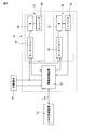
- FIG. 1 is a perspective view schematically showing an outline of a power generation system for carrying out the heliostat direction correcting method according to the present invention.
- FIG. 2 is a front view schematically showing the power generation system of FIG.
- FIG. 3 is a side view schematically showing the outline of the heliostat.
- FIG. 4 is a block diagram showing an outline of the configuration of the heliostat of FIG.
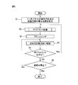
- FIG. 5 is a flowchart showing a procedure for performing the direction correction method of the heliostat according to the first embodiment of the present invention during automatic tracking of the sun.
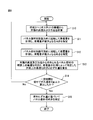
- FIG. 6 is a flowchart for specifically explaining the first embodiment of the method for correcting the direction of the heliostat of the present invention.
- FIG. 1 is a perspective view schematically showing an outline of a power generation system for carrying out the heliostat direction correcting method according to the present invention.
- FIG. 2 is a front view schematically showing the power generation system of FIG.
- FIG. 3 is a side view schematically
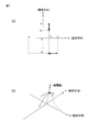
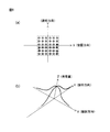
- FIG. 7 is a diagram for explaining the movement of the panel member in the first embodiment of the heliostat direction correcting method of the present invention.
- (a) is a figure which shows the motion of this panel member at the time of searching for the suitable direction of a panel member
- (b) is a graph which shows the electric energy of the elevation direction and turning direction of the panel member measured with the solar cell. It is. The broken arrow in the figure indicates the measurement direction, and the solid arrow indicates the return direction of the body panel.
- FIG. 8 is a flowchart for specifically explaining the second embodiment of the heliostat direction correcting method of the present invention.
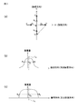
- FIG. 9 is a diagram for explaining the movement of the panel member in the second embodiment of the method for correcting the direction of the heliostat of the present invention.
- FIG. 10 is a flowchart for specifically explaining the third embodiment of the method for correcting the direction of the heliostat of the present invention.
- FIG. 11 is a diagram for explaining the movement of the panel member in the second embodiment of the method for correcting the direction of the heliostat of the present invention.
- (a) is a figure which shows the motion of this panel member at the time of searching for the suitable direction of a panel member
- (b) is a graph which shows the electric energy of the elevation direction and turning direction of the panel member measured with the solar cell.
- (C) is the graph which shows the electric energy of the raising / lowering direction and turning direction of the panel member measured with the solar cell, and shows a different aspect from (b).
- the solid arrow indicates the measurement direction
- the broken arrow indicates the direction of movement of the main body panel in the non-measurement state.
- FIGS. 1 to 4 show an example of a power generation system for performing the direction correcting method according to the first embodiment of the present invention. It is. That is, the power generation system 1 collects a plurality of heliostats 4 that automatically track the moving sun 2 and reflects the sunlight 3 and the reflected light 5 reflected by the heliostat 4 and collects the light. And a solar thermal power generation device 6 that generates power by heat from the reflected light 5.
- the solar thermal power generation device 6 condenses the reflected light 5 reflected by the heliostat 4 and heats a heat medium such as water, oil, or molten salt by the heat of the collected reflected light 5.
- a so-called tower-type configuration is provided in which the light condensing unit 7 is provided on an upper portion of a tower 8 having a predetermined height.
- the solar thermal power generation device 6 includes the tower 8 such as a steel tower, the condensing unit 7 provided at the upper end of the tower 8, and a high-temperature heat medium heated in the condensing unit 7. And a high-temperature storage tank (not shown) provided on the ground.
- a generator (not shown) that generates power by driving a steam turbine with steam generated by heat energy of the heat medium stored in the high-temperature storage tank is provided.
- the heat medium is a molten salt
- a low-temperature storage tank is further provided that stores the heat medium that has been used for generating steam and has a reduced temperature, and supplies the heat medium again to the light collecting unit.
- Each of the heliostats 4 includes a panel member 11 that tracks the moving sun, and a direction adjusting device that adjusts the direction by changing the direction of the panel member 11 so as to automatically track the moving sun 2. 12 respectively.
- the panel member 11 is in the form of a plate having a reflecting member 13 that forms a reflecting surface 13a that reflects infrared rays from the sun 2 and a solar cell 14 that generates power using sunlight 3, and is on one side. With the plate surface as the front surface and the other plate surface as the back surface, sunlight 3 is received on the front surface side, and the sunlight 3 is reflected in the direction of the front surface side.
- the reflecting member 13 reflects the wavelength in the infrared region (about 780 to 2500 nm) in the sunlight reaching the ground surface, and irradiates the condensing unit 7 with the reflected light.
- the solar cell 14 generates power using the wavelength of an area not reflected by the reflecting member 13 during sunlight reaching the ground surface, for example, visible light or ultraviolet light, and can measure the amount of power generation. It is possible.
- the power generation amount of the solar cell 14 is measured by a drive control device 23 (to be described later) in the direction adjusting device 12, and information on the power generation amount is output from the drive control device 23 to a higher-level control device 45 (to be described later). Is done. Accordingly, each heliostat 4 is in a state where the power generation status of the solar cell 14 of the panel member 11 is monitored.
- the transparent solar cell 14 that generates power by ultraviolet rays that is, a so-called artificial crystal solar cell has an infrared ray on the back side (the side opposite to the light receiving surface side of the panel member 11).
- a reflective member 13 such as a reflective film or a reflective mirror is attached.
- the solar cell (artificial crystal solar cell) 14 generates power using the ultraviolet rays in the sunlight 3, while the infrared ray transmitted through the solar cell 14 is reflected by the reflecting member 13.
- the said panel member 11 while attaching the infrared reflective film which reflects only infrared rays as a reflective member on the surface (light-receiving surface) of a well-known solar cell, while reflecting infrared rays by this infrared reflective film, while this infrared rays It is good also as a structure which produces electric power with a solar cell using the ultraviolet-ray, visible light, etc. which permeate
- a known solar cell can be used, such as the above-described artificial crystal solar cell, or a silicon-based semiconductor (for example, amorphous silicon, single crystal silicon, polycrystalline silicon, etc.) or a compound semiconductor (gallium arsenide-based, indium Various solar cells composed of gallium arsenide, chalcopyrite, etc.) and organic semiconductor materials (dye sensitization, organic thin film, etc.) can be used.
- a silicon-based semiconductor for example, amorphous silicon, single crystal silicon, polycrystalline silicon, etc.
- a compound semiconductor gallium arsenide-based, indium
- Various solar cells composed of gallium arsenide, chalcopyrite, etc. and organic semiconductor materials (dye sensitization, organic thin film, etc.) can be used.
- the panel member 11 is given a strength sufficient to withstand an outdoor environment such as rain and wind, regardless of the configuration described above.
- a lattice frame-shaped base portion 15 formed of a metal having excellent rigidity is provided on the back surface side of the reflecting member 13.
- substrate part 15 may be a thing of arbitrary structures, such as plate shape, if rigidity can be provided to the whole panel member.
- the solar cell or the reflecting member itself may be provided with rigidity without providing the base portion 15.
- each heliostat 4 is used, for example, for driving and controlling electric motors 28 and 37 of the elevation means 21 and the turning means 22 described later in the direction adjusting device 12.
- the electric power and the electric power necessary for driving the drive control device 23 are all provided by electric power generated by the solar cell 14 provided in each heliostat 4. Therefore, each heliostat 4 can be individually driven by the electric power generated by each heliostat 4 itself.
- the direction adjusting device 12 can freely change the direction of the reflecting surface 13a of the panel member 11 by adjusting two axes of the elevation direction for raising and lowering the panel member 11 and the turning direction for rotating the panel member 11 horizontally.
- the panel member 11 can track the moving sun 3.
- the direction adjusting device 12 is an elevating unit that raises and lowers the reflective surface 13 a of the panel member 11 in the vertical direction by raising and lowering the panel member 11. 21 and turning means 22 for turning the panel member 11 in the horizontal direction to turn the reflecting surface 13a of the panel member 11 in the left-right direction.
- a drive control device 23 is provided for controlling the operation of the elevation means 21 and the turning means 22 to control the direction of the panel member 11 in the elevation direction and the turning direction.
- the elevating means 21 is disposed on the back side of the panel member 11 and is formed in a bar shape extending in a straight line in the horizontal direction, and the elevating shaft member 25 rotates about its axis.
- a bearing member 26 for raising and lowering that is supported freely and a drive device 27 for raising and lowering that rotates the shaft member 25 for raising and lowering about an axis are provided.
- the raising / lowering bearing member 26 is interconnected with the raising / lowering shaft member 25, and on the upper part of the turning means 22, more specifically, a turning shaft member 35 described later in the turning means 22. It is fixed to the upper side of the. Further, as shown in FIG.
- the drive device 27 for the elevation direction is an electric motor 28 for the elevation direction as an actuator for rotating the elevation shaft member 25 about the axis, and drives the electric motor 28.
- a motor driver 29 for the elevation direction to be controlled is provided.
- it has an up-and-down encoder 30 that detects the number of rotations and the rotation angle of the output shaft of the electric motor 28 and outputs the information to the drive control device 23. Then, by rotating the output shaft of the electric motor 28 forward and backward, it is possible to rotate the panel member 11 up and down by rotating the shaft member 25 for raising and lowering in the forward and backward directions around the axis.
- the turning means 22 includes a turning shaft member 35 formed in a rod shape extending linearly in a substantially vertical direction, and a turning direction driving device 36 for rotating the turning shaft member 35 about an axis. And is attached to the upper end of a pole member 40 that is fixed to the ground and formed in a bar shape extending in the vertical direction.
- the shaft member 35 for turning is fixed to the upper and lower means 21 on the upper side, and the whole panel member 11 including the raising and lowering means 21 is fixed to the upper end of the pole member 40 by the driving device 36 for the turning direction. This part is rotatable around the axis of the turning shaft member 35, that is, in a substantially horizontal direction. Further, as shown in FIG.
- the turning direction driving device 36 has a turning direction electric motor 37 as an actuator for rotating the turning shaft member 35 around the axis, and drives the electric motor 37. And a motor driver 38 for the turning direction to be controlled. Furthermore, it has an encoder 39 for the turning direction that detects the rotation speed, rotation angle, etc. of the output shaft of the electric motor 37 and outputs the information to the drive control device 23. Then, by rotating the output shaft of the electric motor 37 forward and backward, it is possible to rotate the turning shaft member 35 in the forward and reverse directions around the axis, thereby turning the entire panel member 11 in the horizontal direction. It has become.
- the drive control device 23 controls the number of rotations and the rotation angle of the drive devices 27 and 36 for the elevation direction and the turning direction, particularly the electric motors 28 and 37 for the elevation direction and the turning direction, By adjusting the rotation direction and the rotation angle of the shaft member 25 for elevation and the shaft member 35 for turning, respectively, the direction of the panel member 11 in the elevation direction and the turning direction, that is, the elevation angle and the turning angle are controlled. Specifically, the drive control device 23 calculates the position of the sun 2 from the position and time of the heliostat 4, and for the elevation direction output from the encoders 30 and 39 for the elevation direction and the turning direction.
- the elevation direction (elevation angle) and the turning direction (turning angle) of the panel member 11 can be calculated. It has become. Further, based on the calculated position of the sun 2, the panel member 11 tracks the sun 2 within a range in which the heliostat 4 can irradiate the reflected light 5 to the light collecting portion 7 of the solar thermal power generation device 6. The orientation of the panel member 11 can be changed. That is, the electric motors 28 and 37 required for the driving devices 27 and 36 for the elevation direction and the turning direction (more specifically, the motor drivers 29 and 38 for the elevation direction and the turning direction).
- the normal operation as the heliostat 4 that is, automatically tracking the moving sun 2 reflects the sunlight 3 by the panel member 11, and directs the reflected light toward the condensing unit 7 of the solar power generation device 6.
- the control of the operation of irradiating is performed by the drive control device 23.
- the drive control devices 23 of all the heliostats 4 in the power generation system 1 are controlled by the above-described upper control device 45 and output from the drive control devices 23 of the respective heliostats 4.
- Various information such as the direction of the heliostat 4 (strictly the direction of the panel member 11) is input, and necessary information such as time information and various operation commands are output to each heliostat 4. Can be done.
- each heliostat 4 and the upper control device 45 are connected wirelessly so that various types of information can be communicated with each other. Therefore, electrical connection by wire such as a cable is not performed.
- the drive control device 23 of each heliostat 4 is independent for each heliostat, and electrical connection by wire / wireless is not directly performed with the drive control device of other heliostats. .
- the direction adjusting device 12 is caused by wind or rain with respect to the heliostat 4, particularly the panel member 11, in addition to the operation of automatically tracking the sun 2 to the panel member 11, which is a normal operation as the heliostat 4.
- the panel member 11 is provided with a function of performing an avoiding operation of tilting the panel member 11 to a state where the plate surface is substantially horizontal (that is, a state where the reflection surface 13a is directed substantially in the vertical direction).
- the direction adjusting device 12 corrects (aligns) the direction of the heliostat 4, more specifically, the panel member 11 (specifically, the reflecting surface 13 a) that actually reflects the sunlight 5 in an appropriate direction. It has a function to operate.
- the higher-order control device 45 performs the drive control device 23 of the direction adjustment device 12 in each heliostat 4. This is executed by outputting an operation command.
- FIG. 5 shows the power generation system 1 having the above-described configuration, for example, when the heliostat 4 is installed (that is, when the direction of the heliostat 4 is corrected for the first time) or during the automatic tracking operation of the sun 2. It is a flowchart which shows the procedure in the case of correcting direction. The correction of the direction of the heliostat 4 is performed as an operation different from the automatic tracking operation of the sun of the heliostat 4.
- step S1 the direction of the heliostat 4 (direction of the panel member 11) before the direction correction at the start of the correction operation is set as the origin.
- the direction serving as the origin is the direction in which the panel member 11 faces immediately after the heliostat 4 is installed.
- the panel member 11 faces the correction operation start time during the automatic tracking operation.
- step S2 the direction of the heliostat 4 is corrected (alignment). A specific procedure for correcting the direction of the heliostat 4 in step S2 of this embodiment will be described later.
- step S3 the reflected light 5 reflected by the heliostat 4 that is the target of direction correction is concentrated on a partial region of the condensing unit 7 of the solar thermal power generation device 6 together with the reflected light reflected by other heliostats. Then, addressing is performed to adjust the irradiation position of the light collecting unit 7 of the heliostat 4 whose direction is to be corrected so as not to be irradiated. This addressing is performed in relation to the irradiation position of the reflected light reflected by other heliostats on the light collecting unit 7, and the reflected light 5 reflected by the heliostat 4 in the power generation system 1 is reflected by the light collecting unit 7.
- the orientation of the elevation direction and / or the turning direction of the panel member 11 of each heliostat 4 is adjusted so as to be irradiated as uniformly as possible.
- the heliostat 4 is divided so that the number of heliostats that irradiate reflected light to each section of the light collecting section 7 is substantially the same after dividing the light collecting section 7 into a plurality of equal sections.
- the orientation of the panel member 11 is adjusted.
- the addressing is performed by outputting a drive command from the host control device 45 to the drive control device 23 of each heliostat 4.
- step S ⁇ b> 4 the sunlight 3 is reflected by the heliostat 4 for which the addressing has been completed, and the condensed light 7 is irradiated with the reflected light 5.
- step S5 whether or not the heliostat 4 that irradiates the reflected light 5 to a predetermined position of the light collecting unit 7 by addressing is in the direction in which the power generation amount of the solar cell 14 of the panel member 11 is the highest, that is, It is determined whether or not the heliostat 4 is oriented in an appropriate direction. Then, if correction of the direction of the heliostat 4 is necessary again, the process returns to step S2 to correct the direction, and if correction of the direction is unnecessary, the process proceeds to the next step S6.
- step S6 it is determined whether or not the automatic tracking of the sun 2 by the heliostat 4 is stopped. If not, the process returns to step S4 to continue the automatic tracking to reflect the sunlight 3, and the reflected light. 5 is applied to the light collecting unit 7. When the automatic tracking of the sun 2 is stopped due to sunset or other maintenance, the operation of the heliostat 4 ends.
- the basic flow of the method for correcting the direction of the heliostat 4 of the present invention is that the direction of the panel member 11 of the heliostat 4 is moved within a certain range, and the power generation of the solar cell 14 provided in the panel member 11 is performed. Based on the amount, an appropriate measurement direction that the panel member 11 should face is detected. On the other hand, the theoretically appropriate direction that the panel member 11 should face is calculated based on the theoretical position of the sun calculated from the position coordinates of the heliostat 4 and the time. Eventually, the direction adjusting device 12 corrects the direction of the panel member 11 based on the amount of deviation between the actually measured appropriate direction and the theoretically appropriate direction.
- the schematic flow of the method for correcting the direction of the heliostat 4 in this embodiment first calculates the theoretical position of the sun calculated from the position coordinates of the heliostat 4 and the time. Next, the direction of the panel member 11 is changed by the direction adjusting device 12 to detect the direction of the panel member 11 at which the power generation amount of the solar cell 14 is maximized, and the power generation amount of the solar cell 14 is maximum. Is determined as an appropriate measured direction that the panel member 11 should face. Then, based on the theoretical position of the sun, the theoretical proper direction that the panel member 11 of the heliostat 4 should face is calculated, and the theoretical proper direction and the proper proper direction in the actual measurement are calculated. Find the amount of deviation. Thereafter, the direction correction of the heliostat 4 is completed by correcting the orientation of the panel member 11 of the heliostat 4 in the elevation direction and / or the turning direction based on the deviation amount.
- FIG. 6 is a flowchart showing a specific procedure for correcting the direction of the heliostat 4 in this embodiment, and will be described below based on this flowchart.
- step S ⁇ b> 10 the position of the sun 2, that is, the altitude and direction of the sun 2 are calculated from the relationship between the correction operation start time and the position coordinates of the heliostat 4.
- the time information is input from the host control device 45 to the drive control device 23, and the altitude and direction of the sun 2 are calculated by the drive control device 23.
- step S11 the panel member 11 is continuously rotated in a turning range from the origin position set in step S1 by a certain range.
- the position is searched for a position where the power generation amount of the solar cell 14 of the panel member 11 is maximized in the turning direction.
- the rotation of the panel member 11 in the turning direction is controlled by the direction adjusting device 12 by outputting a drive command from the drive control device 23 to the motor driver 38 for the turning direction of the turning means 22.
- the turning shaft member 35 is rotated around the axis by the turning direction electric motor 37.
- the range from ⁇ x to xrad in the left-right direction with respect to the origin position (for example, ⁇ to + ⁇ rad with respect to the origin position, for example, depending on the origin position).
- the drive control device 23 can constantly measure the amount of power generated by the solar cell 14 of the panel member 11 during rotation of the panel member 11 in the turning direction, and irradiate the light collecting unit 7 with the reflected light 5. Within this range, the direction in which the power generation amount of the solar cell 14 is highest in the turning direction of the panel member 11 is detected. Further, during the rotation of the panel member 11 in the turning direction, the drive control device 23 uses the rotation speed and rotation angle information of the output shaft of the turning direction electric motor 37 output from the turning direction encoder 39. Based on the direction of the turning direction of the panel member 11, specifically, the turning angle of the panel member 11 with respect to the origin position is always calculated.
- the process which correlates each turning angle and the information of the electric power generation amount of the said solar cell 14 is performed.
- the power generation amount of the solar cell 14 changes with time according to the direction of the panel member 11, but finally the power generation amount of the solar cell 14 is the highest.
- the direction of the turning direction of the panel member 11 is detected, and the direction is specified as an appropriate direction of the turning direction that the panel member 11 should face in the turning direction.
- the origin position in the case of FIG. 7A, the intersection of the horizontal axis (X axis) and the vertical axis (Y axis)
- the panel member 11 After the member 11 rotates in the left-right direction within the range of ⁇ x to xrad, the panel member 11 reaches the position (orientation) where the amount of power generation in the turning direction of the solar cell 14 is the highest, that is, the appropriate turning direction x 1. I'm back.
- the intersection position of the X-axis and the Y-axis is the direction in which the amount of power generated by the solar cell 14 is highest (that is, the appropriate direction x 1 in the turning direction).
- step S12 the panel member 11 is set to the origin position set in step S1 in the proper orientation of the turning direction of the panel member 11 detected and specified in step S11.
- the position where the amount of power generated by the solar cell of the panel member 11 is maximized in the elevation direction at the same time as the direction is changed by continuously rotating (raising and lowering) a certain range in the elevation direction on the basis of the position in the elevation direction.
- Search for. The rotation of the panel member 11 in the elevation direction is controlled by the motor driver 29 by outputting a drive command from the drive control device 23 in the direction adjusting device 12 to the motor driver 29 for the elevation direction of the elevation means 21.
- the drive control device 23 can constantly measure the amount of power generated by the solar cell of the panel member 11 during rotation of the panel member 11 in the elevation direction, and can irradiate the light collecting unit 7 with the reflected light 5. Within the range, the direction in which the power generation amount of the solar cell 14 is highest in the elevation direction of the panel member 11 is detected.
- the drive control device 23 is based on information on the rotational speed and rotation angle of the output shaft of the elevation-direction electric motor 28 output from the elevation-direction encoder 30.
- the elevation angle of the panel member 11 is always calculated based on the orientation of the panel member 11 in the elevation direction, specifically, the position of the origin position in the elevation direction.
- the process which correlates each elevation angle and the information of the electric power generation amount of the said solar cell 14 is performed.
- the power generation amount of the solar cell 14 changes with time according to the direction of the panel member 11, but finally the power generation amount of the solar cell 14 is the highest.
- the direction of the rising / lowering direction is detected, and the direction is specified as an appropriate direction of the rising / lowering direction that the panel member 11 should face in the rising / lowering direction.
- the panel member 11 has the direction x 1 specified in the step 11 in which the solar cell 14 has the highest power generation amount in the turning direction of the panel member 11. Rotating in the range of -y to yrad while maintaining Thereafter, the panel member 11 has returned to the position (orientation) where the power generation amount of the solar cell 14 is highest in the elevation direction, that is, the appropriate orientation y 1 in the elevation direction. Also in FIG. 7B, the panel member 11 measures the power generation amount of the solar cell in the range of ⁇ y to yrad with respect to the origin position in the turning direction of the panel member 11, It can be seen that the amount has returned to the highest direction y 1 . Finally, the direction x 1 in the turning direction and the direction y 1 in the elevation direction are the directions in which the power generation amount of the solar cell 14 of the panel member 11 is the highest in the turning direction and the elevation direction of the panel member 11.
- step S13 a deviation amount between the theoretically appropriate direction of the panel member 11 and the actually measured appropriate direction is calculated. That is, a theoretically appropriate direction that the panel member 11 should face is calculated based on the altitude and direction of the sun calculated in step S10. On the other hand, the panel member 11 faces the direction in which the power generation amount of the solar cell 14 of the panel member 11 is maximized, which is specified by the appropriate direction of the turning direction and the elevation direction determined in Step S11 and Step S12. The proper orientation in power measurement. And the deviation
- step S14 the procedure from step S10 to step S13, that is, the step of calculating the altitude and direction of the sun 2 from the relationship with the position coordinates of the heliostat 4, the detection of the appropriate direction of the turning direction of the panel member 11,
- the step of specifying, the step of detecting and specifying an appropriate direction of the elevation direction of the panel member 11, the step of determining the amount of deviation between the theoretically appropriate direction of the panel member 11 and the measured appropriate direction are constant. It is determined whether or not it has been performed twice or more sequentially with a time interval. If the procedure from step S10 to step S13 is executed twice or more after a predetermined time interval, the process proceeds to the next step S15, and if it is executed only once, the process returns to step S10.
- Step S10 to Step S13 the series of steps from Step S10 to Step S13 is executed once, and further when executing a series of steps, it is preferable that the steps are executed after, for example, about 2 to 3 hours.
- the reason why the procedure from step S10 to step S13 is executed twice or more with a predetermined time interval is to make the direction of the panel member 11 more surely and stably suitable. That is, when the procedure from Step S10 to Step S13 is performed only once, the proper orientation in actual measurement of the panel member 11 at that time is specified, and the deviation amount from the theoretical proper orientation is calculated. It is possible. However, for example, there is a shift in the rotation direction of the turning shaft member of the turning means around the axis line or the rotation direction of the raising / lowering shaft member around the axis line of the raising / lowering means. There may be a deviation (shift angle) in the rotational direction of the member 11 in the turning direction or the elevation direction.
- the procedure from the step S10 to the step S13 is executed twice or more after a certain time interval, and the proper orientation in measurement and the theoretical direction of the panel member 11 at each time is obtained.
- the amount of deviation from the appropriate direction is calculated.
- the deviation angle in each direction when the panel member 11 is rotated in the turning direction and the elevation direction is also calculated, and the panel member is obtained when the panel member 11 is rotated in each direction.
- the degree to which the direction of 11 is shifted is specified.
- the direction of the panel member 11 can be corrected by taking into account (for example, adding or subtracting) the deviation angle at each rotation of the panel member 11 in the turning direction and the elevation direction.
- step S15 correction is made so that the panel member 11 always faces the appropriate direction based on the deviation amount between the theoretically appropriate direction and the actually measured direction obtained in step S13. I do. That is, in the drive control device 23 of the direction adjusting device 12 and the motor drivers 29 and 38 for the elevation direction and the turning direction, the rotational speeds of the output shafts of the electric motors 28 and 37 for the elevation direction and the turning direction. Then, the control amount such as the rotation angle is corrected based on the shift amount so that each of the electric motors 28 and 37 can be driven so that the panel member 11 at each time points in an appropriate direction.
- the panel member 11 described above is calculated based on the deviation amount between the actually measured proper direction and the theoretically appropriate direction of the panel member 11 at each time, which is calculated in step S13.
- the shift angle in each direction during rotation in the turning direction or elevation direction is calculated.
- the control amount such as the rotation speed and the rotation angle is corrected.
- the heliostat 4 can track the sun 2 in a state where the panel member 11 is oriented in an appropriate direction, the reflected light 5 can be stably irradiated to the light collecting unit 7, Thereby, in the solar thermal power generation device 6, power can be generated efficiently and stably by the heat generated by the reflected light 5 collected on the light collecting unit 7.
- the appropriate direction in which the panel member 11 should face the direction in which the power generation amount of the solar cell 14 provided in the panel member 11 itself is the highest is detected and specified. Therefore, it is very easy to specify an appropriate direction of the panel member 11 as compared with the conventional case, and human labor is hardly required. Therefore, there is no need to correct the orientation of the panel member for each heliostat as in the prior art, or to prepare and correct various other members, and it is extremely easy to correct the orientation of the panel member 11 of the heliostat 4. Can be done.
- the power generation system includes a large number of heliostats, for example.
- each heliostat can independently correct the direction regardless of the presence of other heliostats. Therefore, the correction of the direction of all the heliostats 4 included in the power generation system 1 can be performed at the same timing. As a result, the correction time of the direction of the heliostat 4 as the entire power generation system 1 is compared with the conventional one. It can be significantly shortened.
- each heliostat 4 can rotate the panel member 11 by the electric power generated by the solar cell 14 of the panel member 11 of the heliostat 4.
- the power used by the direction adjusting device 12 or the like can be provided in the heliostat 4. . Therefore, since it is not necessary to supply the electric power for driving the heliostat 4 from another place, such as the solar thermal power generation apparatus 6, the electric wire for power transmission etc. is unnecessary.
- each heliostat 4 has the direction adjusting device 12 that controls the rotation of the panel member 11 connected to the host control device 45 by radio, and is directly connected to other heliostats. Since no general connection is made, a cable for transmitting information is also unnecessary. Therefore, the first embodiment has an advantage that each heliostat 4 can independently cope with various operations. This advantage is very effective especially when the power generation system has many heliostats.
- the panel member 11 when correcting the direction of the heliostat, the panel member 11 is rotated in the turning direction and the elevation direction, and at the same time, the power generation amount of the solar cell 14 of the panel member 11 is constantly measured. Then, by detecting the direction of the panel member 11 that maximizes the amount of power generation from the amount of power generation that changes over time during the rotation of the panel member 11, the appropriate direction that the panel member 11 should face is determined. It was. However, in the second embodiment described below, in the method for correcting the specific direction of the heliostat, the detection method for the direction in which the power generation amount of the solar cell 14 of the panel member 11 becomes the highest is the same as that of the first embodiment. It is different from the form.
- FIG. 8 is a flowchart showing a specific procedure of the direction correcting method according to the second embodiment in the heliostat direction correcting method of the present invention.
- the elevation direction and the turning direction of the panel member 11 of the heliostat 4 are set at a constant angle within a predetermined range of the elevation direction or the turning direction of the panel member 11.
- the power generation amount of the solar cell 14 at each angular position is measured respectively.
- the power generation amount for the entire elevation direction and the entire turning direction is estimated, and the direction in which the power generation amount is highest is specified from the estimated power generation amount.
- the power generation system 1 in which the heliostat direction correction method according to the second embodiment is implemented has basically the same configuration as the power generation system used in the first embodiment, and thus the same. Detailed description will be omitted.
- the direction of the heliostat is basically corrected by the same procedure except that the detection method in the direction in which the power generation amount of the solar cell 14 of the panel member 11 is the highest is different from that in the first embodiment. Therefore, in the heliostat 4 of the power generation system 1 having the above-described configuration, the procedure for correcting the direction during the initial setting or during the automatic tracking operation of the sun is performed according to the procedure shown in FIG. Detailed description is omitted.
- step S ⁇ b> 20 the position of the sun 2, that is, the altitude and direction of the sun 2 are calculated from the relationship between the correction operation start time and the position coordinates of the heliostat 4. At this time, the time information is input from the host control device 45 to the drive control device 23, and the altitude and direction of the sun are calculated by the drive control device 23.
- this step S20 is the same process as step S10 of the said 1st Embodiment.
- step S21 the panel member 11 is changed by a predetermined angle in the elevation direction or the turning direction within a predetermined range of the elevation direction or the turning direction of the panel member 11, and the sun at each angular position is changed.
- Each power generation amount of the battery 14 is measured.
- the turning direction is set in the up / down direction within the range of -x to xrad in the left / right direction in the turning direction.
- the angle is changed by a certain angle (for example, by 1 mrad (0.001 rad)) in a range from ⁇ y to yrad in the vertical direction.
- the power generation amount of the solar cell 14 of the panel member 11 at each angle position in the elevation direction and the turning direction is measured for each angle position.
- Each range of the elevation direction or the turning direction in which the orientation of the panel member 11 is changed is arbitrarily set according to the direction of the set origin position. For example, when the direction of the heliostat 4 is corrected for the first time when the heliostat 4 is installed, the panel member 11 is likely to be oriented in a direction that is not so much related to the position of the sun 2. Since the power generation amount of the solar cell 14 should be measured in a wide range, it is preferable to change the direction of the panel member 11 in the range of ⁇ to ⁇ rad in the elevation direction and the turning direction, respectively.
- each range of the elevation direction or the turning direction in which the direction of the panel member 11 is changed is the case where the direction correction of the heliostat 4 is performed for the first time. It may be set narrower than the above.
- the angle when changing the panel member 11 to the elevation direction or the turning direction is arbitrary as long as the power generation amount for the whole elevation direction and the whole turning direction can be estimated based on the measured power generation amount of the solar cell.
- the angle is such that the number of measurement points can be secured so that the power generation amount of the solar cell can be obtained by extrapolation or interpolation.
- the first direction of the turning direction (in the case of FIG. 9A, the direction from the left side to the right side of the panel member).
- the panel member 11 is rotated by the same angle and the direction is changed, and the amount of power generated by the solar cell 14 is measured at each angle position (the white circle in FIG. 9A is Represents a measurement point.)
- the direction is changed by rotating the panel member 11 by a certain angle upward in the elevation direction, and this time, the first direction in the turning direction is changed to the first direction.
- the direction of the panel member 11 is rotated by the same angle in the opposite direction (in the case of FIG.
- the second direction the direction from the right side to the left side of the panel member 11; hereinafter referred to as the second direction).
- the power generation amount of the solar cell 14 is measured at each angular position.
- the panel member 11 is repeatedly moved back and forth in the turning direction and the orientation of the panel member 11 is changed in the up-and-down direction.
- the power generation amount of the solar cell 14 at each angular position is measured while changing the elevation direction or the turning direction by a certain angle.
- the direction adjusting device 12 uses the motor controller 38 for the turning direction of the turning means 22 from the drive control device 23 or the elevation means.
- a drive command is output to each motor driver 29 for the elevation direction 21.
- the turning shaft member 35 or the raising and lowering shaft member 25 is rotated around the axis by the electric motors 37 and 28 for the turning direction or the elevation direction controlled by the motor drivers 38 and 29, respectively.
- the control of the angle when the panel member 11 is rotated in the turning direction or the elevation direction is acquired by the encoders 39 and 30 for the turning direction or the elevation direction, respectively.
- the power generation amount of the solar cell 14 is measured by the drive control device 23, and whenever the angle of the panel member 11 in the turning direction or the elevation direction is changed, the solar cell 14 at the position of the angle is measured. Measure power generation. And the process which links
- step S22 based on the power generation amount of the solar cell 14 at each angle position in the turning direction and the elevation direction of the panel member 11 measured in the step S21, the solar cell for each of the turning direction and the elevation direction of the panel member. 14 is estimated (strictly speaking, changes in the respective power generation amounts when the panel member moves in the elevation direction and the turning direction), and the direction in which the power generation amount is maximized is specified.
- the estimation of the power generation amount of the solar cell with respect to the elevation direction and the turning direction of the panel member is specifically performed by extrapolating or interpolating each power generation amount measured with respect to the elevation direction and the turning direction of the panel member, respectively. This is done by inserting.
- step S21 the relationship between the power generation amount of the solar cell 14 and the position of each angle in the turning direction and the elevation direction of the panel member 11 (the direction of the panel member 11) is specified. Yes. Therefore, as shown in FIG. 9B, the relationship between the direction of the turning direction of the panel member 11 and the amount of power generation of the solar cell 14, and the relationship between the direction of the elevation direction of the panel member 11 and the amount of power generation of the solar cell 14. Can be represented as graphs (in the case of FIG. 9B), the Z axis is the amount of power generated by the solar cell 14, the X axis is the direction of the turning direction of the panel member 11, and the Y axis is the direction of the elevation. ).
- the power generation amount measured in step S21 is data obtained by changing the orientation of the panel member 11 by a certain angle
- the direction of the panel member 11 and the power generation amount are shown in the graph (FIG. 9B).
- Plot points in the graph Therefore, a series of power generation amounts in the entire elevation direction and in the entire turning direction are obtained by extrapolating or interpolating numerical values between adjacent points in the graph.
- various methods such as linear extrapolation or linear interpolation using a linear function, or extrapolation or interpolation using a spline connecting points with a curve can be used.
- the power generation of the solar cell 14 in each of the turning direction and the turning direction from the relationship between the direction of the turning direction and the elevation direction of the panel member 11 obtained by extrapolation or interpolation and the power generation amount of the solar cell 14.
- the direction of the panel member 11 having the highest amount is estimated. And in the turning direction of the panel member 11, let the direction of the panel member 11 with the highest electric power generation amount of the said solar cell 14 be an appropriate direction of the turning direction in the panel member 11.
- the direction of the panel member 11 having the highest power generation amount of the solar cell 14 is set to an appropriate direction of the elevation direction of the panel member 11.
- step S23 a deviation amount between the theoretically appropriate direction of the panel member 11 and the actually measured appropriate direction is obtained. That is, the theoretically appropriate direction that the panel member should face is calculated based on the altitude and direction of the sun calculated in step S20.
- the direction in which the amount of power generated by the solar cell 14 of the panel member 11 is specified by the appropriate direction of the turning direction and the elevation direction determined in step S22 is determined as the appropriateness in actual measurement of the panel member 11. Specific orientation.
- shift amount of the theoretical appropriate direction of these panel members 11 and the appropriate direction on actual measurement is calculated. Specifically, the shift amounts of the turning direction and the elevation direction of the panel member 11 are calculated.
- step S24 it is determined whether or not the steps from step S20 to step S23 are sequentially performed twice or more. If the procedure from step S20 to step S23 is executed twice or more, the process proceeds to the next step S25, and if it is executed only once, the process returns to step S20. The reason why the procedure from step S20 to step S23 is executed twice or more, and in this step S24, when a series of procedures from step S20 to step S23 are executed once and then a series of procedures are executed further. Execution after a certain period of time (about 2 to 3 hours) is basically the same as in step S14 of the first embodiment.
- step S25 correction is made so that the panel member 11 always faces the appropriate direction based on the deviation amount between the theoretically appropriate direction and the actually measured direction obtained in step S23. I do.
- the correction of the orientation of the panel member 11 is performed in the drive control device 23 of the direction adjusting device 12 and the motor drivers 29 and 38 for the elevation direction and the turning direction, as in the first embodiment. This is performed by correcting the control amount such as the rotation speed and rotation angle of the output shafts of the electric motors 28 and 37 for the elevation direction and the turning direction based on the deviation amount.
- the shift angle in each direction when the panel member 11 is rotated in the turning direction or the elevation direction is calculated, and these shift angles are taken into account.
- step S15 the control amount of the output shafts of the electric motors 28 and 37 in the drive control device 23 and the motor drivers 29 and 38 is corrected.
- step S15 the control amount of the output shafts of the electric motors 28 and 37 in the drive control device 23 and the motor drivers 29 and 38 is corrected.
- the heliostat direction correcting method of this embodiment basically the same effects as those of the first embodiment can be obtained.
- the power generation amount of the solar cell 14 is measured every time the direction of the panel member 11 is changed by a certain angle in the elevation direction or the turning direction. Since a series of power generation amounts in the entire elevation direction and the entire turning direction of the panel member 11 are estimated, there is no need to constantly measure the power generation amount.
- the measurement of the power generation amount of the solar cell is performed while repeating the rotation in the turning direction and the rotation in the elevation direction of the panel member 11 many times, compared with the first embodiment, Since the region for measuring the power generation amount of the solar cell 14 is wide (the power generation amount is measured by directing the panel member 11 in multiple directions), the detection accuracy of the orientation of the panel member where the power generation amount becomes the highest can be improved. There is an advantage that you can.
- FIG. 10 is a flowchart showing a specific procedure of the direction correcting method according to the third embodiment in the heliostat direction correcting method of the present invention.
- the method for correcting the direction of the heliostat of the third embodiment is different from the first and second embodiments in that the method of detecting the direction in which the power generation amount of the solar cell 14 of the panel member 11 is the highest. Is different. That is, in the third embodiment, while the orientation of the panel member 11 is continuously changed in either the elevation direction or the turning direction, the sun in the changed elevation direction or the turning direction is changed. The power generation amount of the battery 14 is continuously measured. On the other hand, while continuously changing the panel member 11 in the other direction, the power generation amount of the solar cell 14 in the changed turning direction or elevation direction is measured.
- the direction of the two panel members 11 with the same electric power generation amount of the said solar cell 14 is each specified, and direction of those specified two panel members is determined.
- the direction in which the power generation amount of the solar cell 14 is the highest is detected by assuming the middle direction as the direction in which the power generation amount of the solar cell 14 is the highest.
- the power generation system 1 in which the heliostat direction correction method of the third embodiment is implemented has basically the same configuration as the power generation system 1 used in the first embodiment.
- the same reference numerals are given and detailed description is omitted.
- the helio is basically performed in the same procedure except that the detection method in which the power generation amount of the solar cell 14 of the panel member 11 is the highest is different from that in the first embodiment. Correct the direction of the stat. Therefore, in the heliostat 4 of the power generation system 1 having the above-described configuration, the procedure for correcting the direction during the automatic tracking operation of the sun 2 is performed according to the procedure shown in FIG. Is omitted.
- step S ⁇ b> 30 the position of the sun 2, that is, the altitude and direction of the sun 2 are calculated from the relationship between the correction operation start time and the position coordinates of the heliostat 4. At this time, the time information is input from the host control device 45 to the drive control device 23, and the altitude and direction of the sun 2 are calculated by the drive control device 27.
- This step S30 is the same process as step S10 of the first embodiment.
- step S31 while the orientation of the panel member 11 is continuously changed to one of the elevation direction and the turning direction within a predetermined range of the elevation direction or the turning direction of the panel member 11, The power generation amount of the solar cell 14 in the changed elevation direction or turning direction is measured. Further, the direction of the panel member 11 is the other direction (that is, the turning direction if the orientation of the panel member 11 is changed to the elevation direction, and the elevation direction if the orientation is changed to the turning direction). While continuously changing, the power generation amount of the solar cell 14 in the changed turning direction or elevation direction is measured.
- the origin position set in step S1 is used as a reference, and in the case of the turning direction, a range of ⁇ x to xrad in the horizontal direction, the elevation direction In this case, the process is performed in a range of ⁇ y to yrad in the direction in which the panel member 11 is tilted.
- the power generation amount of the solar cell 14 of the panel member 11 is constantly measured.
- Each range of the elevation direction or the turning direction for changing the orientation of the panel member 11 is set according to the direction of the set origin position, and when the panel member 11 is changed to the elevation direction or the turning direction.
- the angle can be arbitrarily set as long as the power generation amount for the entire elevation direction and the entire turning direction can be estimated based on the measured power generation amount of the solar cell. Since it is the same as that of a form, specific description is abbreviate
- the orientation of the panel member 11 is changed to the elevation direction or the turning direction.
- the power generation amount of the obtained solar cell 14 is extrapolated or interpolated as in the case of the second embodiment. It is necessary to determine the change in the amount of power generation depending on the orientation of the panel member 11 in the elevation direction or the turning direction.
- the panel member 11 is kept within a certain range (FIG. 11 (a) while maintaining the orientation of the panel member 11 in the elevation direction at the origin position. a) in the range of ⁇ x to x) in a), the panel member 11 is rotated in a fixed direction (in the case of FIG. 11A, from the left side to the right side of the panel member 11). The amount of power generated by the solar cell 14 is measured while continuously changing.
- the power generation amount of the solar cell 14 is measured only during the rotation of the panel member 11 in the turning direction, only in the direction of a part of the panel members 11, specifically, only in a certain range other than the vicinity of the origin position ( This is performed only in the direction of the solid arrow in the X-axis direction in FIG. 11A, that is, the range of -x to -x 2 and the range of x 2 to x. Then, after the rotation of the panel member 11 in the turning direction is finished, the panel member 11 is kept within a certain range (FIG. 11A) while maintaining the orientation of the panel member 11 at the origin position in the turning direction.
- the panel member 11 is continuously rotated in a certain direction (in this case, the direction in which the panel member 11 is rotated in the upper direction of the panel member 11) by rotating in the up-and-down direction in the range of -y to y in the middle). While changing, the power generation amount of the solar cell 14 is measured. At this time, the amount of power generated by the solar cell 14 is measured only during the rotation of the panel member 11 in the elevation direction, only in the direction of some panel members 11, that is, in a certain range other than the vicinity of the origin position (in FIG. 11A). Only the direction of the solid arrow in the Y-axis direction, that is, the range of ⁇ y to ⁇ y 2 and the range of y 2 to y) is performed.
- the operation of the direction adjusting device 12 when changing the orientation of the panel member 11 to the turning direction or the elevation direction, the control of the rotation of the panel member 11 in the turning direction or the elevation direction, etc. are basically described above. Since it is the same as Embodiment 1, detailed description is abbreviate
- the drive control device 22 measures the amount of power generated by the solar cell 14, and the electric motors 37 for the turning direction and the elevation direction output from the encoders 39 and 30 for the turning direction and the elevation direction. , 28 based on the rotation speed and rotation angle information of the output shafts 28, the direction of the turning direction and the elevation direction of the panel member 11 is always calculated, and the direction of the panel member 11 and the information on the power generation amount of the solar cell 14 are associated with each other.
- the point of processing is the same as in the first embodiment.
- step S ⁇ b> 32 two orientations of the panel member 11 having the same power generation amount of the solar cell 14 are specified for the elevation direction and the turning direction of the panel member 11, and the two specified panel members 11.
- An intermediate direction is assumed as the direction of the panel member 11 where the power generation amount of the solar cell 14 is the highest, and is specified as an appropriate direction.
- the power generation amount of the solar cell 14 according to the direction of the turning direction and the elevation direction of the panel member 11 measured in the step S31.
- the vertical axis represents the power generation amount and the horizontal axis. Is expressed as a graph with the orientation of the panel member. Further, on this graph, after specifying two directions (points on the graph) of the panel member 11 having the same power generation amount of the solar cell 14, an intermediate between the directions of the two specified panel members 11 is specified.
- the relationship between the power generation amount of the solar cell 14 and the direction of the panel member 11 is usually represented by a curve as shown in FIG. 9B or FIG. 9C.
- the shape of this curve is a symmetric figure with the perpendicular lines L 1 and L 2 passing through the point where the power generation amount of the solar cell 14 is the highest as the axis of symmetry. Therefore, on this graph, the direction of the panel member (the point on the graph) where the power generation amount is the same in each of the region where the power generation amount of the solar cell 14 is increasing and the region where the power generation amount is decreasing. ) Appear (points A 1 and B 1 in FIG. 9B, points A 2 and B 2 in FIG. 9C).
- points C 1 , C indicating the intermediate directions of points A 1 , B 1 , points A 2 , B 2 on the graph indicating the directions of the two panel members 11 having the same power generation amount of the solar cell 14. Since 2 is positioned on the symmetry axes L 1 and L 2 , it is possible to specify the direction of the panel member 11 having the highest power generation amount of the solar cell 14. Therefore, since the middle direction of the two panel members 11 having the same power generation amount of these solar cells 14 can be assumed to be the direction of the panel member 11 having the highest power generation amount of the solar cells 14, The direction is specified as an appropriate direction that the panel member 11 should face.
- the measurement of the power generation amount of the solar cell 14 in step 31 is performed while a part of the panel member 11 is rotated during the rotation of the panel member 11 in the turning direction or the elevation direction. Only the direction range, specifically, the direction of a certain range other than the vicinity of the origin position is performed. Therefore, the obtained power generation amount data of the solar cell 14 is represented as a graph in which the vertical axis indicates the power generation amount and the horizontal axis indicates the direction of the panel member 11, and extrapolation or interpolation is performed for a portion where there is no power generation amount data. Thus, a series of power generation amounts in the elevation direction or the turning direction of the panel member 11 is obtained.
- the panel member 11 having the same amount of power generated by the solar cell 14.
- Two directions (points on the graph) of 11 are specified, and an intermediate direction between the two specified panel members 11 is set to be the same as the direction of the panel member 11 in which the power generation amount of the solar cell 14 is the highest. Then, the direction is set to an appropriate direction that the panel member 11 should face in the turning direction and the elevation direction of the panel member 11.
- step S33 a deviation amount between the theoretically appropriate direction of the panel member 11 and the actually measured appropriate direction is obtained. That is, the theoretically appropriate direction that the panel member should face is calculated based on the altitude and direction of the sun calculated in step S30. On the other hand, in the actual measurement that the panel member 11 should face in the appropriate direction of the turning direction and the elevation direction of the panel member 11 specified in the step S32, the power generation amount of the solar cell 14 of the panel member is maximized. The proper orientation. And the deviation
- step S34 it is determined whether or not the steps from step S30 to step S33 are sequentially performed twice or more. If the procedure from step S30 to step S33 is executed twice or more, the process proceeds to the next step S35, and if it is executed only once, the process returns to step S30. The reason why the procedure from step S30 to step S33 is executed twice or more, and in this step S34, when the sequence of steps from step S30 to step S33 is executed once and then a sequence of steps is executed further. Execution after a certain period of time (about 2 to 3 hours) is basically the same as in step S14 of the first embodiment.
- step S35 correction is made so that the panel member 11 always faces the appropriate direction based on the deviation amount between the theoretically appropriate direction and the actually measured direction obtained in step S33. I do.
- the correction of the orientation of the panel member 11 is performed in the same manner as in the first and second embodiments.
- the drive control device 23 of the direction adjusting device 12 and the motor drivers 29 for the elevation direction and the turning direction, In 38 the control amount such as the rotation speed and the rotation angle of the output shafts of the electric motors 28 and 37 for the elevation direction and the turning direction is corrected based on the deviation amount.
- the shift angle in each direction when the panel member 11 is rotated in the turning direction or the elevation direction is calculated, and these shift angles are taken into account.
- step S15 the control amount of the output shafts of the electric motors 28 and 37 in the drive control device 23 and the motor drivers 29 and 38 is corrected.
- step S15 the control amount of the output shafts of the electric motors 28 and 37 in the drive control device 23 and the motor drivers 29 and 38 is corrected.
- the heliostat direction correcting method of this embodiment basically the same effects as those of the first embodiment can be obtained.
- the directions of two panel members 11 having the same power generation amount are respectively specified, and the intermediate direction between the two specified panel members 11 is determined as the power generation amount of the solar cell 14. This is effective when the difference in the amount of power generation is small in the vicinity of the direction in which the power generation amount is the highest and it is difficult to specify the direction in which the power generation amount is the highest. .
- the direction correction method of the present invention is performed on the heliostat 4 of the power generation system 1 in which the solar power generation device 6 has a tower type configuration.
- the direction correction method of the present invention condenses the reflected light reflected by the center mirror and the tower having the center mirror as the first light collecting portion that reflects the reflected light from the heliostat further downward.
- a receiver serving as a second light condensing unit, and the heat medium may be heated by reflected light collected by the receiver.
- the heliostat 4 may not be provided with one panel member 11 as in the first to third embodiments, and one heliostat is provided with a plurality of panel members. It may be a thing.
- the configuration of the elevation means and the turning means of the heliostat direction adjusting device may be any configuration as long as the panel member can be rotated in the elevation direction and the turning direction.
- the correction of the orientation of the panel member 11 of the heliostat 4 is performed by changing the orientation of the panel member 11 by the direction adjusting device 12 in two directions of the elevation direction and the turning direction. This is done by adjusting.
- the method for correcting the direction of the heliostat of the present invention detects the direction in which the power generation amount of the solar cell is highest within the range in which reflected light can be applied to the condensing unit of the solar thermal power generation device, and the direction is detected. If it can correct
- the orientation of the panel member 11 is corrected by driving the direction adjusting device 12 with the electric power generated by the solar cell 14 of the panel member 11.
- the direction adjustment device 12 may be driven by the power generated by the solar power generation device 6 to correct the orientation of the panel member 11.
- the power generated by the solar cell 14 of the panel member 11 is used only for driving the direction adjusting device 12, but the power generation efficiency is high as the solar cell of the panel member.
- the power generated by the solar cell may be transmitted to a place other than the heliostat and output.
- the power generation system is configured to perform so-called hybrid power generation by solar thermal power generation by a solar thermal power generation apparatus and solar power generation by a solar cell of a heliostat.
- each heliostat and the power transmission source or the power transmission It is necessary to electrically connect the tip with a cable or the like.
- the solar member 11 when detecting the direction in which the power generation amount of the solar cell 14 of the panel member 11 is the highest, the solar member 11 is first changed while continuously changing the direction of the panel member 11 in the turning direction. After measuring the power generation amount of the battery 14, the power generation amount is measured by continuously changing in the elevation direction. However, after measuring the power generation amount of the solar cell while continuously changing the orientation of the panel member in the elevation direction, the power generation amount of the solar cell is determined by measuring the power generation amount while continuously changing in the turning direction. The highest direction may be detected.
- the orientation of the panel member 11 when detecting the direction in which the power generation amount of the solar cell 14 of the panel member 11 is the highest, the orientation of the panel member 11 is set at a certain angle in the first direction of the turning direction. It changes and measures the electric power generation amount of the solar cell 14 in the position of each angle. Thereafter, the direction of the panel member 11 is changed by a certain angle in the elevation direction, and then the direction of the panel member 11 is changed by a certain angle in the second direction of the turning direction to generate power by the solar cell 14 at each angle position. The operation of measuring the amount is repeated.
- the orientation of the panel member is a certain angle in the turning direction. Change, this time repeat the operation of measuring the power generation amount of the solar cell at the position of each angle by changing the direction of the panel member by a certain angle in the direction opposite to the elevation direction, that is, the lower direction of the panel member, The direction in which the power generation amount of the solar battery of the panel member becomes the highest may be detected based on the obtained power generation amount data.
- the solar cell in the orientation of the plurality of panel members May be measured, and the orientation of the panel member at which the power generation amount of the solar cell becomes the highest may be detected based on the data of the power generation amount.
- the orientation of the panel member 11 is continuously changed to a constant turning direction
- the solar cell After measuring the power generation amount of 14, the solar cell while continuously changing the orientation of the panel member 11 in a certain elevation direction while maintaining the orientation of the turning direction of the panel member 11 at the origin position. 14 power generation amounts are measured.
- the power generation amount of the solar cell is measured while continuously changing the direction of the panel member in the turning direction. May be.
- the said 3rd Embodiment while measuring the electric power generation amount of the solar cell 14, changing the direction of the panel member 11 continuously to a raising / lowering direction or a turning direction, only a part of direction, That is, it is carried out only in a certain range direction other than the vicinity of the origin position.
- the measurement of the power generation amount of the solar cell may be always performed when the direction of the panel member is continuously changed to the elevation direction or the turning direction. In this case, unlike the third embodiment, it is not necessary to obtain a series of power generation amounts in the elevation direction and the turning direction by extrapolation or interpolation based on the data of the power generation amount obtained by measurement.
- the direction in which the power generation amount of the solar cell 14 of the panel member 11 becomes the highest is detected at least twice or more after a predetermined time interval, and each detection is performed.
- the amount of deviation between the actually measured proper direction and the theoretical proper direction of the panel member 11 at the time is calculated.
- the deviation angle generated when the panel member 11 rotates in the elevation direction and the turning direction is calculated, and each of the elevation direction and the turning direction of the panel member 11 is calculated.
- the orientation of the panel member 11 is corrected by taking the deviation angle into account.
- the difference in the calculated amount of deviation is used to move the panel member in the elevation direction and the turning direction. It is not necessary to calculate the deviation angle that occurs during rotation. For example, when the deviation angle generated when the panel member is rotated in the elevation direction and the turning direction can be grasped in advance by another operation such as maintenance, the deviation amount is not necessarily calculated two times or more.
- the known deviation angle is calculated based on the rotation speed of the output shaft of each electric motor for the elevation direction or the turning direction. It is necessary to take into account the correction of the control amount of the rotation angle.
- the rotational speed of the output member of each electric motor for the elevation direction or the rotation direction and the control amount of the rotation angle are corrected for the rotation direction in the elevation direction and the turning direction in the panel member. Even if it has already been performed, it is not always necessary to calculate the deviation amount twice or more.
Landscapes
- Engineering & Computer Science (AREA)
- Life Sciences & Earth Sciences (AREA)
- Sustainable Development (AREA)
- Physics & Mathematics (AREA)
- Sustainable Energy (AREA)
- Thermal Sciences (AREA)
- Chemical & Material Sciences (AREA)
- Combustion & Propulsion (AREA)
- Mechanical Engineering (AREA)
- General Engineering & Computer Science (AREA)
- Photovoltaic Devices (AREA)
- Control Of Position Or Direction (AREA)
Abstract
本発明は、集光した反射光によって発電を行う発電システムにおけるヘリオスタットの、適切な方向への補正を簡単且つ確実に行うことが可能なヘリオスタットの方向補正方法を得ることを目的とする。本発明の構成は、ヘリオスット(4)の方向の補正を、ヘリオスタット(4)が太陽熱発電装置(6)の集光部(7)に反射光(5)を照射可能な範囲内において、方向調整装置(12)によりパネル部材(11)の向きを変えてパネル部材(11)の太陽電池14の発電量が最も高くなる向きを検出し、太陽電池(14)の発電量が最大となる向きを、パネル部材(11)が向くべき実測上の適正な向きとして決定すると共に、ヘリオスタット(5)の位置座標と時刻とから算出される理論上の太陽の位置に基づいてパネル部材(11)が向くべき理論上の適正な向きを算出し、これらの実測上の適正な向きと理論上の適正な向きとのずれ量に基づいて、パネル部材(11)の向きを方向調整装置(12)によって補正する。
Description
本発明は、太陽を自動追尾するヘリオスタットにより太陽光を反射して集光し、その集光した反射光によって発電を行う発電システムにおいて、前記ヘリオスタットが適切な方向に向くようにするための方向補正方法に関する。
近年、石油等の化石燃料の高騰や枯渇化の問題、あるいは地球環境の保護等の観点から、例えば風力や地熱、太陽熱等の化石燃料を使用しないクリーンエネルギーの研究や開発が行われている。
このようなクリーンエネルギーにおいて、特に太陽光を集光し、その集光した光によって熱媒体を加熱し、その熱媒体を熱源として水蒸気を発生させ、その水蒸気によって蒸気タービンを駆動させることにより発電を行う太陽熱発電が出力面で有利であることから特に注目されている。
このようなクリーンエネルギーにおいて、特に太陽光を集光し、その集光した光によって熱媒体を加熱し、その熱媒体を熱源として水蒸気を発生させ、その水蒸気によって蒸気タービンを駆動させることにより発電を行う太陽熱発電が出力面で有利であることから特に注目されている。
このような太陽熱発電を行う発電システムとしては、太陽を自動追尾して太陽光を反射するヘリオスタットと、該ヘリオスタットにより反射された反射光を集光する集光部が上部に設けられたタワーとを備え、該集光部に集光された反射光によって前記熱媒体を加熱するタワー式のものが知られている。
あるいは、前記ヘリオスタットと、上部側に、該ヘリオスタットにより反射された反射光をさらに下方向けに反射させる、第1の集光部となるセンターミラーが設置されたタワーと、該センターミラーによって反射された反射光を集光する第2の集光部となるレシーバとを備え、該レシーバに集光された反射光によって熱媒体を加熱する、ビームダウン式のものも知られている。
あるいは、前記ヘリオスタットと、上部側に、該ヘリオスタットにより反射された反射光をさらに下方向けに反射させる、第1の集光部となるセンターミラーが設置されたタワーと、該センターミラーによって反射された反射光を集光する第2の集光部となるレシーバとを備え、該レシーバに集光された反射光によって熱媒体を加熱する、ビームダウン式のものも知られている。
この種の太陽熱発電を行う発電システムは、いずれも、ヘリオスタッドが、移動する太陽をしっかりと自動追尾すると共に、常に適切な方向を向いて太陽光、特に赤外線(赤外光)を予め定められた方向に確実に反射することにより、その反射光を前記集光部に確実且つ安定的に照射することがきわめて重要である。
しかしながら、実際には、ヘリオスタットは、その設置位置の誤差や、設置した地盤の変化等によって適正な方向を向かない場合がある。
また、ヘリオスタットにおいては、太陽光を反射させるパネル部材の向きを変えて太陽を自動追尾させる位置調整装置が、設計誤差や成形上の誤差を有していたり、あるいは経年劣化による誤差等が生じたりするなどして、ヘリオスタッドが当初の予定通りの方向を向かない、あるいは向かなくなる可能性がある。
しかしながら、実際には、ヘリオスタットは、その設置位置の誤差や、設置した地盤の変化等によって適正な方向を向かない場合がある。
また、ヘリオスタットにおいては、太陽光を反射させるパネル部材の向きを変えて太陽を自動追尾させる位置調整装置が、設計誤差や成形上の誤差を有していたり、あるいは経年劣化による誤差等が生じたりするなどして、ヘリオスタッドが当初の予定通りの方向を向かない、あるいは向かなくなる可能性がある。
そうすると、ヘリオスタットが太陽光を集光部に向けて反射させることができなくなり、熱媒体を加熱するための熱量が不足し、発電システムが予定している出力を確保することが困難になる。
特に、広大な敷地にヘリオスタットを数千~数万台設置するような大規模な発電システムの場合、ヘリオスタットの位置によっては集光部との間が数km離れてしまうため、ヘリオスタットが反射する反射光の方向がわずかにずれただけでも該反射光が集光部に当たらないという事態が生じる。
特に、広大な敷地にヘリオスタットを数千~数万台設置するような大規模な発電システムの場合、ヘリオスタットの位置によっては集光部との間が数km離れてしまうため、ヘリオスタットが反射する反射光の方向がわずかにずれただけでも該反射光が集光部に当たらないという事態が生じる。
そのため、前記ヘリオスタットにおいては、ヘリオスタットの方向、より具体的には実際に太陽光を反射するパネル部材の反射面の方向を定期的に補正する作業が必要となる。
このようなヘリオスタットの方向の補正を行う手段として、例えば特許文献1や特許文献2に記載されているような技術が存在する。
このようなヘリオスタットの方向の補正を行う手段として、例えば特許文献1や特許文献2に記載されているような技術が存在する。
前記特許文献1には、ヘリオスタットにより反射される反射光の光軸上に太陽光の追尾ガイドを設置すると共に、該追尾ガイドのガイド軸の同軸上に光学望遠鏡を取付けて、該光学望遠鏡を用いて目視で反射光の照射方向を確認した上で、照射方向が適正な位置となるように前記追尾ガイドのガイド軸の方向を補正することにより、ヘリオスタットの方向を補正する技術が開示されている。
しかしながら、ヘリオスタットを用いて太陽光の反射光を集光する発電システムの場合、多数のヘリオスタットを用いるのが通常であるため、各ヘリオスタットが反射する反射光の照射方向を光学望遠鏡によって目視でそれぞれ確認し、追尾ガイドの調整を行うのは膨大な労力が必要であり、また、人間の目視に依存することから補正の精度にばらつきが生じる可能性もある。
しかしながら、ヘリオスタットを用いて太陽光の反射光を集光する発電システムの場合、多数のヘリオスタットを用いるのが通常であるため、各ヘリオスタットが反射する反射光の照射方向を光学望遠鏡によって目視でそれぞれ確認し、追尾ガイドの調整を行うのは膨大な労力が必要であり、また、人間の目視に依存することから補正の精度にばらつきが生じる可能性もある。
一方、前記特許文献2には、ヘリオスタットからの反射光が照射されている位置と、該ヘリオスタットの方向制御に際して出力されている指令照射位置との差異に基づいて、ヘリオスタットの方向を補正する方法が開示されている。
具体的には、集光部が設けられているタワーに該集光部とは別の集光用のターゲットを設置した上で、そのターゲットに対してヘリオスタットから反射光を照射した状態でターゲットと反射光の照射位置との位置関係をカメラで撮影する。そして、その撮影データから得られた反射光の重心位置と、ヘリオスタットの方向を制御するコントローラから出力されている指令照射位置との誤差を算出し、その算出された誤差データに基づいて方向補正データを作成し前記コントローラにより補正制御を行う。
しかしながら、この特許文献2に記載の方法の場合、各ヘリオスタットから集光用のターゲットに対して反射光を照射して、該ターゲットと反射光の照射位置との位置関係のデータを個別に取得する必要がある。また、前記ターゲットに対する反射光の照射位置を確実に把握するためには、そのターゲットに対して一度に多くのヘリオスタットから反射光を照射することができない。
そのため、ヘリオスタットの方向の補正には多くの時間を要し、また補正作業も非常に面倒である。
具体的には、集光部が設けられているタワーに該集光部とは別の集光用のターゲットを設置した上で、そのターゲットに対してヘリオスタットから反射光を照射した状態でターゲットと反射光の照射位置との位置関係をカメラで撮影する。そして、その撮影データから得られた反射光の重心位置と、ヘリオスタットの方向を制御するコントローラから出力されている指令照射位置との誤差を算出し、その算出された誤差データに基づいて方向補正データを作成し前記コントローラにより補正制御を行う。
しかしながら、この特許文献2に記載の方法の場合、各ヘリオスタットから集光用のターゲットに対して反射光を照射して、該ターゲットと反射光の照射位置との位置関係のデータを個別に取得する必要がある。また、前記ターゲットに対する反射光の照射位置を確実に把握するためには、そのターゲットに対して一度に多くのヘリオスタットから反射光を照射することができない。
そのため、ヘリオスタットの方向の補正には多くの時間を要し、また補正作業も非常に面倒である。
本発明の技術的課題は、太陽を自動追尾するヘリオスタットにより太陽光を反射して集光し、その集光した反射光によって発電を行う発電システムにおいて、前記ヘリオスタットの適切な方向への補正を簡単且つ確実に行うことが可能なヘリオスタットの方向補正方法を提供することにある。
前記課題を解決するため、本発明のヘリオスタットの方向補正方法は、太陽からの赤外線を反射する反射面を形成する反射部材、及び太陽光によって発電を行う太陽電池を備えたパネル部材と、該パネル部材の向きを、移動する太陽を自動追尾するように変更して方向調整する方向調整装置とを有するヘリオスタットと、該ヘリオスタットにより反射された反射光が集光される集光部を有し、該集光部に集光した反射光による熱によって発電を行う太陽熱発電装置とを備えた発電システムにおける、前記ヘリオスタットの方向を補正する方法であって、前記方向調整装置により前記パネル部材の向きを変えて、前記ヘリオスタットが前記太陽熱発電装置における集光部に反射光を照射可能な範囲内において該パネル部材の太陽電池の発電量が最も高くなる向きを検出し、その太陽電池の発電量が最大となる向きを、そのパネル部材が向くべき実測上の適正な向きとして決定すると共に、前記ヘリオスタットの位置座標と時刻とから算出される理論上の太陽の位置に基づいて前記パネル部材が向くべき理論上の適正な向きを算出し、これらの実測上の適正な向きと理論上の適正な向きとのずれ量に基づいて、そのパネル部材の向きを前記方向調整装置によって補正するものである。
さらに、本発明においては、前記パネル部材の太陽電池の発電量が最も高くなる向きの検出は、該パネル部材の向きをそのパネル部材の俯仰方向と旋回方向とのいずれか一方の方向に連続的に変更しながら、その変更した俯仰方向又は旋回方向において前記太陽電池の発電量が最も高くなるパネル部材の向きを特定した後、該パネル部材の向きを他方の方向に連続的に変更しながら、その変更した旋回方向又は俯仰方向の方向において前記太陽電池の発電量が最も高くなるパネル部材の向きを特定することにより行うことができる。
または、前記パネル部材の太陽電池の発電量が最も高くなる向きの検出は、該パネル部材の俯仰方向と旋回方向との向きを、予め定めたそのパネル部材の俯仰方向及び旋回方向の範囲において一定角度ずつ変更すると共に、各角度の位置における前記太陽電池の発電量をそれぞれ計測した後、その計測した発電量に基づいて前記パネル部材の俯仰方向及び旋回方向についての発電量をそれぞれ推定し、その推定した発電量から発電量が最も高くなるパネル部材の向きを特定することにより行うことができる。
この場合においては、前記パネル部材の俯仰方向及び旋回方向についての前記太陽電池の発電量の推定は、該パネル部材の俯仰方向及び旋回方向について計測した各発電量をそれぞれ外挿又は内挿することにより行うことが好ましい。
あるいは、前記パネル部材の太陽電池の発電量が最も高くなる向きの検出は、該パネル部材の向きをそのパネル部材の俯仰方向と旋回方向とのいずれか一方の方向に連続的に変更しながら、その変更した俯仰方向又は旋回方向の前記太陽電池の発電量を連続的に計測すると共に、前記パネル部材の向きを他方の方向に変更しながら、その変更した旋回方向又は俯仰方向の前記太陽電池の発電量を計測した後、前記パネル部材の俯仰方向と旋回方向とのそれぞれについて、発電量が同じ2つのパネル部材の向きを各々特定して、それらの特定した2つのパネル部材の向きの中間の向きを、前記太陽電池の発電量が最も高くなるパネル部材の向きと擬制することにより行うことができる。
また、本発明においては、前記パネル部材の向きの補正は、該パネル部材の俯仰方向及び旋回方向の向きを前記方向調整装置で補正することによって行うことができる。
さらに、本発明においては、前記パネル部材の向きの補正は、一定時間空けて少なくとも2回以上、該パネル部材の太陽電池の発電量が最も高くなる向きの検出を行って、その各検出の時刻におけるパネル部材の実測上の適正な向きと理論上の適正な向きとのずれ量をそれぞれ算出すると共に、それらの算出したずれ量の差に基づいて、前記パネル部材の俯仰方向及び旋回方向への回転時に発生するずれ角度を算出し、該パネル部材のそれらの俯仰方向及び旋回方向の各ずれ角度を加味することにより行うようにすることができる。
さらに、本発明においては、前記パネル部材の向きの補正は、一定時間空けて少なくとも2回以上、該パネル部材の太陽電池の発電量が最も高くなる向きの検出を行って、その各検出の時刻におけるパネル部材の実測上の適正な向きと理論上の適正な向きとのずれ量をそれぞれ算出すると共に、それらの算出したずれ量の差に基づいて、前記パネル部材の俯仰方向及び旋回方向への回転時に発生するずれ角度を算出し、該パネル部材のそれらの俯仰方向及び旋回方向の各ずれ角度を加味することにより行うようにすることができる。
さらに、本発明においては、前記パネル部材の向きの補正は、該パネル部材の太陽電池が発電した電力によって前記方向調整装置を駆動させることにより行うことが好ましい。
本発明によれば、ヘリオスタットのパネル部材に設けられている太陽電池の発電量が最も高くなる向きを検出し、その太陽電池の発電量が最も高くなる向きを該パネル部材が向くべき適正な向きとして、パネル部材の向きを前記方向調整装置によって補正を行う。そのため、従来に比べて、パネル部材の適切な向きの特定をきわめて容易に行うことができ、また人的な労力をほとんど必要としないため、ヘリオスタットの方向の補正を簡単に行うことができる。
また、前記ヘリオスタットは、そのヘリオスタットが備えている太陽電池の発電量に基づいて方向の補正を行うため、例えば多数のヘリオスタットを備えた発電システムであっても、他のヘリオスタットの存在に左右されることなく各ヘリオスタットが独自に方向の補正を行うことが可能である。したがって、発電システムが備えているヘリオスタットの方向の補正を同じタイミングで行うことができ、発電システム全体としてのヘリオスタットの補正時間を従来に比べて大幅に短縮することができる。
また、前記ヘリオスタットは、そのヘリオスタットが備えている太陽電池の発電量に基づいて方向の補正を行うため、例えば多数のヘリオスタットを備えた発電システムであっても、他のヘリオスタットの存在に左右されることなく各ヘリオスタットが独自に方向の補正を行うことが可能である。したがって、発電システムが備えているヘリオスタットの方向の補正を同じタイミングで行うことができ、発電システム全体としてのヘリオスタットの補正時間を従来に比べて大幅に短縮することができる。
以下、本発明のヘリオスタッドの方向補正方法について詳細に説明するに、図1~図4は本発明の第1の実施の形態に係る方向補正方法を実施するための発電システムの一例を示すものである。
即ち、前記発電システム1は、移動する太陽2を自動追尾して太陽光3を反射させる複数のヘリオスタット4と、該ヘリオスタット4により反射させた反射光5を集光し、その集光した反射光5による熱によって発電を行う太陽熱発電装置6とを備えている。
即ち、前記発電システム1は、移動する太陽2を自動追尾して太陽光3を反射させる複数のヘリオスタット4と、該ヘリオスタット4により反射させた反射光5を集光し、その集光した反射光5による熱によって発電を行う太陽熱発電装置6とを備えている。
前記太陽熱発電装置6は、前記ヘリオスタット4により反射した反射光5を集光して、その集光した反射光5の熱により、水や油、溶融塩等の熱媒体を加熱する集光部7を備えたもので、この実施の形態においては、所定の高さを有するタワー8の上部に前記集光部7が設けられた、いわゆるタワー式の構成としている。
具体的に、この太陽熱熱発電装置6は、鉄塔等の前記タワー8と、該タワー8の上端部に設けられた前記集光部7と、該集光部7において加熱された高温の熱媒体を収容する、地上に設けられた図示しない高温貯蔵タンクとを備えている。さらに、該高温貯蔵タンクに貯蔵された熱媒体の熱エネルギーにより発生させた蒸気によって蒸気タービンを駆動させて発電を行う図示しない発電機を備えている。なお、熱媒体が溶融塩の場合、蒸気発生に使用されて温度が低下した熱媒体を収容して、前記集光部に再度供給させる低温貯蔵タンクがさらに備えられている。
具体的に、この太陽熱熱発電装置6は、鉄塔等の前記タワー8と、該タワー8の上端部に設けられた前記集光部7と、該集光部7において加熱された高温の熱媒体を収容する、地上に設けられた図示しない高温貯蔵タンクとを備えている。さらに、該高温貯蔵タンクに貯蔵された熱媒体の熱エネルギーにより発生させた蒸気によって蒸気タービンを駆動させて発電を行う図示しない発電機を備えている。なお、熱媒体が溶融塩の場合、蒸気発生に使用されて温度が低下した熱媒体を収容して、前記集光部に再度供給させる低温貯蔵タンクがさらに備えられている。
また、前記各ヘリオスタット4は、いずれも、移動する太陽を追尾するパネル部材11と、該パネル部材11の向きを、移動する太陽2を自動追尾するように変更して方向調整する方向調整装置12とを、それぞれ有している。
前記パネル部材11は、太陽2からの赤外線を反射する反射面13aを形成する反射部材13と、太陽光3によって発電を行う太陽電池14とを備えた板体状のものであり、一方側の板面を表面、他方側の板面を裏面として、該表面側において太陽光3を受光し、且つ表面側の方向にその太陽光3を反射している。
前記パネル部材11は、太陽2からの赤外線を反射する反射面13aを形成する反射部材13と、太陽光3によって発電を行う太陽電池14とを備えた板体状のものであり、一方側の板面を表面、他方側の板面を裏面として、該表面側において太陽光3を受光し、且つ表面側の方向にその太陽光3を反射している。
前記反射部材13は、地表に到達する太陽光中の赤外領域の波長(780~2500nm程度)を反射して、その反射光を前記集光部7に照射させるものである。
一方、前記太陽電池14は、地表に到達する太陽光中、前記反射部材13により反射されない領域の波長、例えば可視光線や紫外線等を利用して発電するもので、その発電量を計測することが可能となっている。この太陽電池14の発電量については、前記方向調整装置12における後述する駆動制御装置23で計測されると共に、その発電量の情報は該駆動制御装置23から後述するさらに上位の制御装置45に出力される。したがって、各ヘリオスタット4については、パネル部材11の太陽電池14の発電状況が監視された状態となっている。
一方、前記太陽電池14は、地表に到達する太陽光中、前記反射部材13により反射されない領域の波長、例えば可視光線や紫外線等を利用して発電するもので、その発電量を計測することが可能となっている。この太陽電池14の発電量については、前記方向調整装置12における後述する駆動制御装置23で計測されると共に、その発電量の情報は該駆動制御装置23から後述するさらに上位の制御装置45に出力される。したがって、各ヘリオスタット4については、パネル部材11の太陽電池14の発電状況が監視された状態となっている。
前記パネル部材11の具体的な構成としては、太陽光3中の赤外線を前記反射部材13により反射することができ、且つ太陽光3によって発電できる前記太陽電池14を備えていれば、基本的にどのような構成でもよい。
この実施の形態においては、図3に示すように、紫外線により発電する透明な太陽電池14、いわゆる人工水晶太陽電池の裏面側(パネル部材11の受光面側とは反対の面側)に、赤外線を反射する反射フィルムや反射ミラー等の反射部材13を取付けている。そして、太陽光3中の紫外線を利用して太陽電池(人工水晶太陽電池)14で発電する一方、該太陽電池14を透過した赤外線等を前記反射部材13により反射する構成としている。
この実施の形態においては、図3に示すように、紫外線により発電する透明な太陽電池14、いわゆる人工水晶太陽電池の裏面側(パネル部材11の受光面側とは反対の面側)に、赤外線を反射する反射フィルムや反射ミラー等の反射部材13を取付けている。そして、太陽光3中の紫外線を利用して太陽電池(人工水晶太陽電池)14で発電する一方、該太陽電池14を透過した赤外線等を前記反射部材13により反射する構成としている。
なお、前記パネル部材11としては、公知の太陽電池の表面(受光面)に、反射部材として、赤外線のみを反射する赤外線反射フィルムを取付け、この赤外線反射フィルムにより赤外線を反射させる一方で、該赤外線反射フィルムを透過した紫外線や可視光等を利用して太陽電池で発電を行う構成としてもよい。
この場合、太陽電池としては公知のものを用いることができ、前述の人工水晶太陽電池、あるいはシリコン系半導体(例えばアモルファスシリコン、単結晶シリコン、多結晶シリコン等)や化合物半導体(ガリウムヒ素系、インジウムガリウムヒ素、カルコパイライト系等)、有機半導体材料(色素増感系、有機薄膜系等)から構成された各種太陽電池を用いることができる。
この場合、太陽電池としては公知のものを用いることができ、前述の人工水晶太陽電池、あるいはシリコン系半導体(例えばアモルファスシリコン、単結晶シリコン、多結晶シリコン等)や化合物半導体(ガリウムヒ素系、インジウムガリウムヒ素、カルコパイライト系等)、有機半導体材料(色素増感系、有機薄膜系等)から構成された各種太陽電池を用いることができる。
ここで、前記パネル部材11については、前述のいずれの構成であっても、該パネル部材11自体に雨風等の屋外環境に耐えうるだけの強度を付与されている。
この実施の形態の場合、前記太陽電池14や反射部材13とは別に、前記反射部材13の裏面側に、剛性に優れた金属等により形成された格子枠状の基体部15を設けた構成としている。
なお、前記基体部15はパネル部材全体に剛性を付与できれば板体状等の任意の構成のものであってよい。また、パネル部材11に強度を付与する手段としては、前記基体部15を設けることなく、太陽電池や反射部材自体に剛性を持たせた構成としてもよい。
この実施の形態の場合、前記太陽電池14や反射部材13とは別に、前記反射部材13の裏面側に、剛性に優れた金属等により形成された格子枠状の基体部15を設けた構成としている。
なお、前記基体部15はパネル部材全体に剛性を付与できれば板体状等の任意の構成のものであってよい。また、パネル部材11に強度を付与する手段としては、前記基体部15を設けることなく、太陽電池や反射部材自体に剛性を持たせた構成としてもよい。
さらに、この実施の形態においては、各ヘリオスタット4において必要な電力、例えば、前記方向調整装置12における後述の俯仰手段21や旋回手段22の各電動モータ28,37の駆動や制御等に使用する電力や、駆動制御装置23を駆動させるために必要な電力は、すべて各ヘリオスタット4が備えている太陽電池14により発電された電力により賄われる構成となっている。
したがって、各ヘリオスタット4は、それぞれのヘリオスタット4自身で発電した電力により個別に駆動することが可能である。
したがって、各ヘリオスタット4は、それぞれのヘリオスタット4自身で発電した電力により個別に駆動することが可能である。
また、前記方向調整装置12は、前記パネル部材11を起倒させる俯仰方向と、水平方向に回転させる旋回方向との二軸を調整することにより該パネル部材11の反射面13aの向きを変更自在となっていて、これにより移動する太陽3を前記パネル部材11が追尾することが可能となっている。
具体的に、この実施の形態の方向調整装置12は、図3及び図4に示すように、前記パネル部材11を起倒させて該パネル部材11の反射面13aを上下方向に俯仰させる俯仰手段21と、前記パネル部材11を水平方向に回転させて該パネル部材11の反射面13aを左右方向に旋回させる旋回手段22とを備えている。さらに、これらの俯仰手段21及び旋回手段22の動作を制御して、前記パネル部材11の俯仰方向及び旋回方向の向きを制御する駆動制御装置23を備えている。
具体的に、この実施の形態の方向調整装置12は、図3及び図4に示すように、前記パネル部材11を起倒させて該パネル部材11の反射面13aを上下方向に俯仰させる俯仰手段21と、前記パネル部材11を水平方向に回転させて該パネル部材11の反射面13aを左右方向に旋回させる旋回手段22とを備えている。さらに、これらの俯仰手段21及び旋回手段22の動作を制御して、前記パネル部材11の俯仰方向及び旋回方向の向きを制御する駆動制御装置23を備えている。
前記俯仰手段21は、前記パネル部材11の背面側に配設された、水平方向に直線状に延びる棒状に形成された俯仰用軸部材25と、該俯仰用軸部材25をその軸線まわりに回転自在に支持する俯仰用の軸受部材26と、前記俯仰用軸部材25を軸線回りに回転駆動させる俯仰方向用の駆動装置27とを備えている。
前記俯仰用の軸受部材26は、前記俯仰用軸部材25と相互に連結されている一方で、前記旋回手段22の上部、さらに具体的には、該旋回手段22における後述する旋回用軸部材35の上部側に固定されている。
また、前記俯仰方向用の駆動装置27は、図4に示すように、前記俯仰用軸部材25を軸線まわりに回転させるアクチュエータとしての俯仰方向用の電動モータ28と、該電動モータ28の駆動を制御する俯仰方向用のモータドライバ29とを備えている。さらに、前記電動モータ28の出力軸の回転数や回転角等を検出し、その情報を前記駆動制御装置23に出力する俯仰方向用のエンコーダ30を有している。そして、この電動モータ28の出力軸を正逆回転させることにより、前記俯仰用軸部材25を軸線まわりに正逆方向に回転させて前記パネル部材11を起倒させることが可能となっている。
前記俯仰用の軸受部材26は、前記俯仰用軸部材25と相互に連結されている一方で、前記旋回手段22の上部、さらに具体的には、該旋回手段22における後述する旋回用軸部材35の上部側に固定されている。
また、前記俯仰方向用の駆動装置27は、図4に示すように、前記俯仰用軸部材25を軸線まわりに回転させるアクチュエータとしての俯仰方向用の電動モータ28と、該電動モータ28の駆動を制御する俯仰方向用のモータドライバ29とを備えている。さらに、前記電動モータ28の出力軸の回転数や回転角等を検出し、その情報を前記駆動制御装置23に出力する俯仰方向用のエンコーダ30を有している。そして、この電動モータ28の出力軸を正逆回転させることにより、前記俯仰用軸部材25を軸線まわりに正逆方向に回転させて前記パネル部材11を起倒させることが可能となっている。
一方、前記旋回手段22は、略鉛直方向に直線状に延びる棒状に形成された旋回用軸部材35と、該旋回用軸部材35を軸線回りに回転駆動させる旋回方向用の駆動装置36とを備えていて、地面に固定され且つ鉛直方向に延びる棒状に形成されたポール部材40の上端部に取付けられている。
前記旋回用軸部材35は、上部側に前記俯仰手段21が固定されていて、前記旋回方向用の駆動装置36により、該俯仰手段21を含む前記パネル部材11全体を、該ポール部材40の上端部において旋回用軸部材35の軸線まわり、即ち略水平方向に回転自在としている。
また、前記旋回方向用の駆動装置36は、図4に示すように、前記旋回用軸部材35を軸線まわりに回転させるアクチュエータとしての旋回方向用の電動モータ37と、該電動モータ37の駆動を制御する旋回方向用のモータドライバ38とを備えている。さらに、前記電動モータ37の出力軸の回転数や回転角等を検出し、その情報を前記駆動制御装置23に出力する旋回方向用のエンコーダ39を有している。そして、この電動モータ37の出力軸を正逆回転させることにより、前記旋回用軸部材35を軸線まわりに正逆方向に回転させて、前記パネル部材11全体を水平方向に旋回させることが可能となっている。
前記旋回用軸部材35は、上部側に前記俯仰手段21が固定されていて、前記旋回方向用の駆動装置36により、該俯仰手段21を含む前記パネル部材11全体を、該ポール部材40の上端部において旋回用軸部材35の軸線まわり、即ち略水平方向に回転自在としている。
また、前記旋回方向用の駆動装置36は、図4に示すように、前記旋回用軸部材35を軸線まわりに回転させるアクチュエータとしての旋回方向用の電動モータ37と、該電動モータ37の駆動を制御する旋回方向用のモータドライバ38とを備えている。さらに、前記電動モータ37の出力軸の回転数や回転角等を検出し、その情報を前記駆動制御装置23に出力する旋回方向用のエンコーダ39を有している。そして、この電動モータ37の出力軸を正逆回転させることにより、前記旋回用軸部材35を軸線まわりに正逆方向に回転させて、前記パネル部材11全体を水平方向に旋回させることが可能となっている。
前記駆動制御装置23は、前記俯仰方向用及び旋回方向用の各駆動装置27,36、特に前記俯仰方向用及び旋回方向用の各電動モータ28,37の回転数や回転角を制御して、前記俯仰用軸部材25及び旋回用軸部材35の回転方向や回転角をそれぞれ調整することにより、パネル部材11の俯仰方向及び旋回方向の向き、即ち俯仰角及び旋回角を制御するものである。
具体的にこの駆動制御装置23は、ヘリオスタット4の位置と時刻とから太陽2の位置を算出すると共に、前記俯仰方向用及び旋回方向用の各エンコーダ30,39から出力された俯仰方向用及び旋回方向用の各電動モータ28,37の出力軸の回転数や回転角等の情報に基づいて、前記パネル部材11の俯仰方向(俯仰角)や旋回方向(旋回角)を算出することが可能となっている。
さらに、算出した太陽2の位置に基づいて、ヘリオスタット4によって前記太陽熱発電装置6の集光部7に反射光5を照射可能な範囲内において、前記パネル部材11が太陽2を追尾するように該パネル部材11の向きを変更できるようになっている。即ち、前記俯仰方向用及び旋回方向用の各駆動装置27,36(より具体的には、俯仰方向用及び旋回方向用の各モータドライバ29,38)に対して、必要な電動モータ28,37の回転数や回転角等の情報を含む駆動指令を出力することが可能となっている。
したがって、ヘリオスタット4としての通常の動作、即ち、移動する太陽2を自動追尾して前記パネル部材11により太陽光3を反射し、その反射光を前記太陽熱発電装置6の集光部7に向けて照射するという動作の制御はこの駆動制御装置23によって行われることとなる。
具体的にこの駆動制御装置23は、ヘリオスタット4の位置と時刻とから太陽2の位置を算出すると共に、前記俯仰方向用及び旋回方向用の各エンコーダ30,39から出力された俯仰方向用及び旋回方向用の各電動モータ28,37の出力軸の回転数や回転角等の情報に基づいて、前記パネル部材11の俯仰方向(俯仰角)や旋回方向(旋回角)を算出することが可能となっている。
さらに、算出した太陽2の位置に基づいて、ヘリオスタット4によって前記太陽熱発電装置6の集光部7に反射光5を照射可能な範囲内において、前記パネル部材11が太陽2を追尾するように該パネル部材11の向きを変更できるようになっている。即ち、前記俯仰方向用及び旋回方向用の各駆動装置27,36(より具体的には、俯仰方向用及び旋回方向用の各モータドライバ29,38)に対して、必要な電動モータ28,37の回転数や回転角等の情報を含む駆動指令を出力することが可能となっている。
したがって、ヘリオスタット4としての通常の動作、即ち、移動する太陽2を自動追尾して前記パネル部材11により太陽光3を反射し、その反射光を前記太陽熱発電装置6の集光部7に向けて照射するという動作の制御はこの駆動制御装置23によって行われることとなる。
なお、この実施の形態においては、発電システム1内のすべてのヘリオスタット4の駆動制御装置23は、前述の上位の制御装置45により制御されていて、各ヘリオスタット4の駆動制御装置23から出力されたヘリオスタット4の方向(厳密にはパネル部材11の向き)等の各種情報が入力され、またそれぞれのヘリオスタット4に対して、時刻情報等の必要な情報や、各種の動作指令を出力することができるようになっている。
また、各ヘリオスタット4と前記上位の制御装置45とは無線によって接続され、各種の情報を相互に通信自在となっている。したがって、ケーブル等の有線による電気的な接続は行われていない。
さらに、各ヘリオスタット4の駆動制御装置23は、ヘリオスタット毎に独立しており、他のヘリオスタットの駆動制御装置とは、有線・無線による電気的な接続は直接的には行われていない。
また、各ヘリオスタット4と前記上位の制御装置45とは無線によって接続され、各種の情報を相互に通信自在となっている。したがって、ケーブル等の有線による電気的な接続は行われていない。
さらに、各ヘリオスタット4の駆動制御装置23は、ヘリオスタット毎に独立しており、他のヘリオスタットの駆動制御装置とは、有線・無線による電気的な接続は直接的には行われていない。
ところで、前記方向調整装置12は、ヘリオスタット4としての通常の動作である前記パネル部材11に太陽2を自動追尾させるという動作のほかに、ヘリオスタット4、特にパネル部材11に対する風や雨等による負荷を低減するため、該パネル部材11を、その板面が略水平となる状態(即ち反射面13aが略鉛直方向に向いた状態)にまで倒す回避動作を行わせる機能を備えている。
さらに、前記方向調整装置12は、ヘリオスタット4の方向、より具体的には、実際に太陽光5を反射するパネル部材11(厳密には反射面13a)を適正な向きに補正(アライメント)する動作を行う機能を有している。このヘリオスタット4の方向補正方法については、後で詳述する。
これらの各ヘリオスタット4における太陽2の自動追尾の動作、回避動作、方向補正動作については、前記上位の制御装置45から各ヘリオスタット4における方向調整装置12の駆動制御装置23に対して、それぞれ動作指令が出力されることにより実行される。
さらに、前記方向調整装置12は、ヘリオスタット4の方向、より具体的には、実際に太陽光5を反射するパネル部材11(厳密には反射面13a)を適正な向きに補正(アライメント)する動作を行う機能を有している。このヘリオスタット4の方向補正方法については、後で詳述する。
これらの各ヘリオスタット4における太陽2の自動追尾の動作、回避動作、方向補正動作については、前記上位の制御装置45から各ヘリオスタット4における方向調整装置12の駆動制御装置23に対して、それぞれ動作指令が出力されることにより実行される。
以下、前記構成を有する発電システム1のヘリオスタット4において、該ヘリオスタット4の方向を補正する方法について説明する。
図5は、前記構成を有する発電システム1において、例えば、ヘリオスタット4を設置した場合(即ちヘリオスタット4の方向補正を初めて行う場合)、あるいは太陽2の自動追尾動作中に該ヘリオスタット4の方向の補正を行う場合の手順を示すフローチャートである。
なお、ヘリオスタット4の方向の補正は、該ヘリオスタット4の太陽の自動追尾の動作とは別の動作として行われる。
図5は、前記構成を有する発電システム1において、例えば、ヘリオスタット4を設置した場合(即ちヘリオスタット4の方向補正を初めて行う場合)、あるいは太陽2の自動追尾動作中に該ヘリオスタット4の方向の補正を行う場合の手順を示すフローチャートである。
なお、ヘリオスタット4の方向の補正は、該ヘリオスタット4の太陽の自動追尾の動作とは別の動作として行われる。
ステップS1では、補正動作開始時における方向補正前のヘリオスタット4の方向(パネル部材11の向き)を原点として設定する。なお、この原点となる方向は、ヘリオスタット4を設置した際に該ヘリオスタット4の方向補正を初めて行う場合には、そのヘリオスタット4を設置した直後においてパネル部材11が向いている方向である。また、太陽2の自動追尾動作中に該ヘリオスタット4の方向の補正を行う場合には、自動追尾動作中、その補正動作開始時刻においてパネル部材11が向いている方向である。
ステップS2では、ヘリオスタット4の方向の補正(アライメント)を行う。この実施の形態のステップS2におけるヘリオスタット4の方向の補正の具体的な手順については後述する。
ステップS2では、ヘリオスタット4の方向の補正(アライメント)を行う。この実施の形態のステップS2におけるヘリオスタット4の方向の補正の具体的な手順については後述する。
ステップS3では、方向補正の対象となっているヘリオスタット4が反射した反射光5が、他のヘリオスタットが反射した反射光と共に前記太陽熱発電装置6の集光部7の一部の領域に集中して照射されないよう、その方向補正の対象となっているヘリオスタット4の前記集光部7に対する照射位置を調整するアドレッシングを行う。
このアドレッシングは、他のヘリオスタットが反射した反射光の前記集光部7への照射位置との関係で行われ、発電システム1内のヘリオスタット4が反射する反射光5が該集光部7にできるだけ均等に照射されるように、各ヘリオスタット4のパネル部材11の俯仰方向及び/又は旋回方向の向きを調整する。
例えば、前記集光部7を複数の均等な区画に区分した上で、該集光部7の各区画に対して反射光を照射するヘリオスタットの数が略同数となるように、ヘリオスタット4のパネル部材11の向きを調整することが行われる。
なお、前記アドレッシングは、前記上位の制御装置45から各ヘリオスタット4の駆動制御装置23に対して駆動指令が出力されることにより行われる。
このアドレッシングは、他のヘリオスタットが反射した反射光の前記集光部7への照射位置との関係で行われ、発電システム1内のヘリオスタット4が反射する反射光5が該集光部7にできるだけ均等に照射されるように、各ヘリオスタット4のパネル部材11の俯仰方向及び/又は旋回方向の向きを調整する。
例えば、前記集光部7を複数の均等な区画に区分した上で、該集光部7の各区画に対して反射光を照射するヘリオスタットの数が略同数となるように、ヘリオスタット4のパネル部材11の向きを調整することが行われる。
なお、前記アドレッシングは、前記上位の制御装置45から各ヘリオスタット4の駆動制御装置23に対して駆動指令が出力されることにより行われる。
ステップS4では、アドレッシングが終了したヘリオスタット4によって太陽光3を反射させ、その反射光5を前記集光部7に照射する。
ステップS5では、アドレッシングによって集光部7の所定位置に反射光5を照射しているヘリオスタット4が、パネル部材11の太陽電池14の発電量が最も高くなる方向を向いているか否か、即ちヘリオスタット4が適切な方向を向いているか否かを判断する。
そして、ヘリオスタット4の再度の方向の補正が必要ならばステップS2に戻って方向の補正を行い、方向の補正が不要であれば次のステップS6に進む。
ステップS6では、ヘリオスタット4による太陽2の自動追尾を停止するか否かを判断し、停止しない場合には、ステップS4に戻って自動追尾を続行して太陽光3を反射させ、その反射光5を前記集光部7に照射する。日没やその他のメンテナンス等により太陽2の自動追尾を停止する場合にはヘリオスタット4の動作は終了となる。
ステップS5では、アドレッシングによって集光部7の所定位置に反射光5を照射しているヘリオスタット4が、パネル部材11の太陽電池14の発電量が最も高くなる方向を向いているか否か、即ちヘリオスタット4が適切な方向を向いているか否かを判断する。
そして、ヘリオスタット4の再度の方向の補正が必要ならばステップS2に戻って方向の補正を行い、方向の補正が不要であれば次のステップS6に進む。
ステップS6では、ヘリオスタット4による太陽2の自動追尾を停止するか否かを判断し、停止しない場合には、ステップS4に戻って自動追尾を続行して太陽光3を反射させ、その反射光5を前記集光部7に照射する。日没やその他のメンテナンス等により太陽2の自動追尾を停止する場合にはヘリオスタット4の動作は終了となる。
次に、前記ステップS2で行うヘリオスタット4の方向補正(アライメント)について具体的に説明する。
本発明のヘリオスタット4の方向補正方法の基本的な流れとしては、前記ヘリオスタット4のパネル部材11の向きを一定の範囲内で動かして、該パネル部材11が備えている太陽電池14の発電量に基づいてそのパネル部材11が向くべき計測上の適正な向きを検出する。一方で、前記ヘリオスタット4の位置座標と時刻とから算出される理論上の太陽の位置に基づいて前記パネル部材11が向くべき理論上の適正な向きを算出する。
最終的には、これらの実測上の適正な向きと理論上の適正な向きとのずれ量に基づいて、そのパネル部材11の向きを前記方向調整装置12によって補正する。
本発明のヘリオスタット4の方向補正方法の基本的な流れとしては、前記ヘリオスタット4のパネル部材11の向きを一定の範囲内で動かして、該パネル部材11が備えている太陽電池14の発電量に基づいてそのパネル部材11が向くべき計測上の適正な向きを検出する。一方で、前記ヘリオスタット4の位置座標と時刻とから算出される理論上の太陽の位置に基づいて前記パネル部材11が向くべき理論上の適正な向きを算出する。
最終的には、これらの実測上の適正な向きと理論上の適正な向きとのずれ量に基づいて、そのパネル部材11の向きを前記方向調整装置12によって補正する。
この実施の形態におけるヘリオスタット4の方向補正方法の概略的な流れは、まず、前記ヘリオスタット4の位置座標と時刻とから算出される理論上の太陽の位置を算出する。
次に、前記方向調整装置12によって前記パネル部材11の向きを変更して、前記太陽電池14の発電量が最大となる該パネル部材11の向きを検出し、その太陽電池14の発電量が最大となる方向を、そのパネル部材11が向くべき実測上の適正な向きとして決定する。
そして、前記理論上の太陽の位置に基づいて、そのヘリオスタット4の前記パネル部材11が向くべき理論上の適正な向きを算出し、その理論上の適正な向きと前記実測上の適正な向きとのずれ量を求める。
その後、そのずれ量に基づいて、前記ヘリオスタット4のパネル部材11の俯仰方向及び/又は旋回方向の向きを補正することにより、ヘリオスタット4の方向補正が完了することとなる。
次に、前記方向調整装置12によって前記パネル部材11の向きを変更して、前記太陽電池14の発電量が最大となる該パネル部材11の向きを検出し、その太陽電池14の発電量が最大となる方向を、そのパネル部材11が向くべき実測上の適正な向きとして決定する。
そして、前記理論上の太陽の位置に基づいて、そのヘリオスタット4の前記パネル部材11が向くべき理論上の適正な向きを算出し、その理論上の適正な向きと前記実測上の適正な向きとのずれ量を求める。
その後、そのずれ量に基づいて、前記ヘリオスタット4のパネル部材11の俯仰方向及び/又は旋回方向の向きを補正することにより、ヘリオスタット4の方向補正が完了することとなる。
図6は、この実施の形態におけるヘリオスタット4の方向の補正の具体的な手順を示すフローチャートであり、以下、このフローチャートに基づいて説明する。
まず、ステップS10では、補正動作開始時刻と、ヘリオスタット4の位置座標との関係から太陽2の位置、即ち太陽2の高度及び方位を算出する。このとき、時刻の情報については前記上位の制御装置45から駆動制御装置23に入力され、太陽2の高度及び方位については該駆動制御装置23において算出される。
まず、ステップS10では、補正動作開始時刻と、ヘリオスタット4の位置座標との関係から太陽2の位置、即ち太陽2の高度及び方位を算出する。このとき、時刻の情報については前記上位の制御装置45から駆動制御装置23に入力され、太陽2の高度及び方位については該駆動制御装置23において算出される。
次に、ステップS11では、図7(a),図7(b)に示すように、前記パネル部材11を、ステップS1において設定した前記原点位置から旋回方向に一定の範囲だけ連続的に回転させて向きを変更すると同時に、旋回方向において該パネル部材11の太陽電池14の発電量が最大になる位置を探す。
前記パネル部材11の旋回方向への回転は、前記方向調整装置12において、駆動制御装置23から旋回手段22の旋回方向用のモータドライバ38に駆動指令を出力して、該モータドライバ38に制御された旋回方向用の電動モータ37によって前記旋回用軸部材35を軸線まわりに回転させることにより行う。このとき、前記パネル部材11については、例えば前記原点位置を基準として、左右方向に-x~xradの範囲(原点位置にもよるが、例えば該原点位置を基準として-π~+πrad)で連続的に回転させる。
前記パネル部材11の旋回方向への回転は、前記方向調整装置12において、駆動制御装置23から旋回手段22の旋回方向用のモータドライバ38に駆動指令を出力して、該モータドライバ38に制御された旋回方向用の電動モータ37によって前記旋回用軸部材35を軸線まわりに回転させることにより行う。このとき、前記パネル部材11については、例えば前記原点位置を基準として、左右方向に-x~xradの範囲(原点位置にもよるが、例えば該原点位置を基準として-π~+πrad)で連続的に回転させる。
一方、前記駆動制御装置23は、前記パネル部材11の旋回方向への回転中、該パネル部材11の太陽電池14の発電量を常時計測して、前記集光部7に反射光5を照射可能な範囲内において、パネル部材11の旋回方向で最も太陽電池14の発電量が高くなる向きを検出する。
また、前記パネル部材11の旋回方向への回転中、前記駆動制御装置23は、旋回方向用のエンコーダ39から出力される旋回方向用の電動モータ37の出力軸の回転数や回転角の情報に基づいて、パネル部材11の旋回方向の向き、具体的には、前記原点位置を基準としたパネル部材11の旋回角を常時算出する。そして、それぞれの旋回角と前記太陽電池14の発電量の情報とを関連付ける処理を行う。
前記パネル部材11の旋回方向への回転中においては、太陽電池14の発電量はパネル部材11の向きに応じて経時的に変化するが、最終的に、前記太陽電池14の発電量が最も高くなったパネル部材11の旋回方向の向きを検出し、その向きを、該パネル部材11が旋回方向において向くべき、旋回方向の適切な向きとして特定する。
また、前記パネル部材11の旋回方向への回転中、前記駆動制御装置23は、旋回方向用のエンコーダ39から出力される旋回方向用の電動モータ37の出力軸の回転数や回転角の情報に基づいて、パネル部材11の旋回方向の向き、具体的には、前記原点位置を基準としたパネル部材11の旋回角を常時算出する。そして、それぞれの旋回角と前記太陽電池14の発電量の情報とを関連付ける処理を行う。
前記パネル部材11の旋回方向への回転中においては、太陽電池14の発電量はパネル部材11の向きに応じて経時的に変化するが、最終的に、前記太陽電池14の発電量が最も高くなったパネル部材11の旋回方向の向きを検出し、その向きを、該パネル部材11が旋回方向において向くべき、旋回方向の適切な向きとして特定する。
この実施の形態においては、図7(a)に示すように、前記原点位置(図7(a)の場合、横軸(X軸)と縦軸(Y軸)の交点)を基準として、パネル部材11が左右方向に-x~xradの範囲を回転した後、該パネル部材11は太陽電池14の旋回方向の発電量が最も高かった位置(向き)、即ち旋回方向の適切な向きx1まで戻っている。
なお、図7(b)は、X軸とY軸との交点位置を太陽電池14の発電量が最も高い向き(即ち旋回方向の適切な向きx1)としているが、この図7(b)においても、パネル部材11の旋回方向において、前記原点位置を基準とした-x~xradの範囲の太陽電池の発電量を計測した後、発電量が最も高かった向きx1まで戻っていることがわかる。
なお、図7(b)は、X軸とY軸との交点位置を太陽電池14の発電量が最も高い向き(即ち旋回方向の適切な向きx1)としているが、この図7(b)においても、パネル部材11の旋回方向において、前記原点位置を基準とした-x~xradの範囲の太陽電池の発電量を計測した後、発電量が最も高かった向きx1まで戻っていることがわかる。
さらに、ステップS12では、図7(a)に示すように、ステップS11で検出、特定した該パネル部材11の旋回方向の適正な向きにおいて、前記パネル部材11を、ステップS1で設定した前記原点位置の俯仰方向の位置を基準として、俯仰方向に一定の範囲だけ連続的に回転(起倒)させて方向を変更すると同時に、俯仰方向において該パネル部材11の太陽電池の発電量が最大になる位置を探す。
前記パネル部材11の俯仰方向への回転は、前記方向調整装置12における駆動制御装置23から俯仰手段21の俯仰方向用のモータドライバ29に駆動指令を出力して、該モータドライバ29に制御された俯仰方向用の電動モータ28によって前記俯仰用軸部材25を軸線回りに回転させることにより行う。このとき、前記パネル部材11については、例えば前記原点位置の俯仰方向の位置を基準として、該パネル部材11が起倒する方向に-y~yradの範囲(原点位置にもよるが、例えば該原点位置を基準として-π~+πrad)で連続的に回転させる。
前記パネル部材11の俯仰方向への回転は、前記方向調整装置12における駆動制御装置23から俯仰手段21の俯仰方向用のモータドライバ29に駆動指令を出力して、該モータドライバ29に制御された俯仰方向用の電動モータ28によって前記俯仰用軸部材25を軸線回りに回転させることにより行う。このとき、前記パネル部材11については、例えば前記原点位置の俯仰方向の位置を基準として、該パネル部材11が起倒する方向に-y~yradの範囲(原点位置にもよるが、例えば該原点位置を基準として-π~+πrad)で連続的に回転させる。
一方、前記駆動制御装置23は、前記パネル部材11の俯仰方向への回転中、該パネル部材11の太陽電池の発電量を常時計測して、前記集光部7に反射光5を照射可能な範囲内において、パネル部材11の俯仰方向で最も太陽電池14の発電量が高くなる向きを検出する。
前記パネル部材の俯仰方向への回転中において、前記駆動制御装置23は、俯仰方向用のエンコーダ30から出力される俯仰方向用の電動モータ28の出力軸の回転数や回転角の情報に基づいてパネル部材11の俯仰方向の向き、具体的には、前記原点位置の俯仰方向の位置を基準としたパネル部材11の俯仰角を常時算出する。そして、それぞれの俯仰角と前記太陽電池14の発電量の情報とを関連付ける処理を行う。
前記パネル部材11の俯仰方向への回転中においては、太陽電池14の発電量はパネル部材11の向きに応じて経時的に変化するが、最終的に、前記太陽電池14の発電量が最も高くなった俯仰方向の向きを検出し、その向きを、前記パネル部材11が俯仰方向において向くべき、俯仰方向の適切な向きとして特定する。
前記パネル部材の俯仰方向への回転中において、前記駆動制御装置23は、俯仰方向用のエンコーダ30から出力される俯仰方向用の電動モータ28の出力軸の回転数や回転角の情報に基づいてパネル部材11の俯仰方向の向き、具体的には、前記原点位置の俯仰方向の位置を基準としたパネル部材11の俯仰角を常時算出する。そして、それぞれの俯仰角と前記太陽電池14の発電量の情報とを関連付ける処理を行う。
前記パネル部材11の俯仰方向への回転中においては、太陽電池14の発電量はパネル部材11の向きに応じて経時的に変化するが、最終的に、前記太陽電池14の発電量が最も高くなった俯仰方向の向きを検出し、その向きを、前記パネル部材11が俯仰方向において向くべき、俯仰方向の適切な向きとして特定する。
この実施の形態においては、図7(a)に示すように、パネル部材11は、前記ステップ11で特定した、該パネル部材11の旋回方向において太陽電池14の発電量が最も高かった向きx1を保ったまま、俯仰方向に-y~yradの範囲で回転している。その後、前記パネル部材11は、俯仰方向において太陽電池14の発電量が最も高かった位置(向き)、即ち俯仰方向の適切な向きy1まで戻っている。
また、図7(b)においても、前記パネル部材11は、該パネル部材11の旋回方向において、前記原点位置を基準とした-y~yradの範囲の太陽電池の発電量を計測した後、発電量が最も高かった向きy1まで戻っていることがわかる。
そして、最終的には、旋回方向の向きx1及び俯仰方向の向きy1が、パネル部材11の旋回方向及び俯仰方向においてパネル部材11の太陽電池14の発電量が最も高かった向きとなる。
また、図7(b)においても、前記パネル部材11は、該パネル部材11の旋回方向において、前記原点位置を基準とした-y~yradの範囲の太陽電池の発電量を計測した後、発電量が最も高かった向きy1まで戻っていることがわかる。
そして、最終的には、旋回方向の向きx1及び俯仰方向の向きy1が、パネル部材11の旋回方向及び俯仰方向においてパネル部材11の太陽電池14の発電量が最も高かった向きとなる。
ステップS13では、前記パネル部材11の理論上の適正な向きと実測上の適正な向きとのずれ量を算出する。
即ち、前記ステップS10において算出された太陽の高度及び方位に基づいて前記パネル部材11が向くべき理論上の適正な向きを算出する。
一方で、前記ステップS11及びステップS12において決定した旋回方向及び俯仰方向の適切な向きで特定される、該パネル部材11の太陽電池14の発電量が最大となる方向を、そのパネル部材11が向くべき実測上の適正な向きとする。
そして、これらのパネル部材11の理論上の適正な向きと実測上の適正な向きとのずれ量を算出する。具体的には、前記パネル部材11の旋回方向及び俯仰方向のそれぞれのずれ量を算出する。
即ち、前記ステップS10において算出された太陽の高度及び方位に基づいて前記パネル部材11が向くべき理論上の適正な向きを算出する。
一方で、前記ステップS11及びステップS12において決定した旋回方向及び俯仰方向の適切な向きで特定される、該パネル部材11の太陽電池14の発電量が最大となる方向を、そのパネル部材11が向くべき実測上の適正な向きとする。
そして、これらのパネル部材11の理論上の適正な向きと実測上の適正な向きとのずれ量を算出する。具体的には、前記パネル部材11の旋回方向及び俯仰方向のそれぞれのずれ量を算出する。
ステップS14では、前記ステップS10~ステップS13までの手順、即ち、ヘリオスタット4の位置座標との関係から太陽2の高度及び方位を算出するステップ、パネル部材11の旋回方向の適切な向きの検出、特定を行うステップ、パネル部材11の俯仰方向の適切な向きの検出、特定を行うステップ、パネル部材11の理論上の適正な向きと実測上の適正な向きとのずれ量を求めるステップを、一定時間を空けて順次2回以上行ったか否かを判断する。
前記ステップS10~ステップS13までの手順を、一定時間を空けて2回以上実行した場合には次のステップS15に進み、1回しか実行していない場合はステップS10まで戻る。そして、前記パネル部材11の太陽電池14の発電量が最も高くなる向きを検出した時刻における該パネル部材11の計測上の適正な向きと、理論上の適正な向きとのずれ量をそれぞれ算出する。
なお、前記ステップS10~ステップS13までの一連の手順を1度実行した場合、さらに一連の手順を実行する場合、例えば2~3時間程度空けて実行することが好ましい。
前記ステップS10~ステップS13までの手順を、一定時間を空けて2回以上実行した場合には次のステップS15に進み、1回しか実行していない場合はステップS10まで戻る。そして、前記パネル部材11の太陽電池14の発電量が最も高くなる向きを検出した時刻における該パネル部材11の計測上の適正な向きと、理論上の適正な向きとのずれ量をそれぞれ算出する。
なお、前記ステップS10~ステップS13までの一連の手順を1度実行した場合、さらに一連の手順を実行する場合、例えば2~3時間程度空けて実行することが好ましい。
ここで、前記ステップS10~ステップS13までの手順を、一定時間を空けて2回以上実行するのは、パネル部材11の向きをより確実且つ安定的に適切な向きとするためである。
即ち、前記ステップS10~ステップS13までの手順を1回のみ行った場合、その時点におけるパネル部材11の実測上の適正な向きを特定し、且つ理論上の適正な向きとのずれ量を算出することは可能である。
しかしながら、例えば旋回手段の旋回用軸部材の軸線まわりの回転方向あるいは俯仰手段の俯仰用軸部材の軸線まわりの回転方向にずれが発生するなどして、旋回手段22や俯仰手段21に起因するパネル部材11の旋回方向あるいは俯仰方向への回転方向のずれ(ずれ角度)が生じる場合がある。この場合においては、仮に1回のみのずれ量に基づいてパネル部材の方向の補正を行ったとしても、その後の自動追尾時にパネル部材が旋回方向あるいは俯仰方向に回転すると、旋回方向や俯仰方向のずれ角度に伴って、パネル部材11の向きに再度ずれが生じる可能性がある。
このようなパネル部材11の旋回方向あるいは俯仰方向への回転方向のずれを考慮すると、パネル部材11の方向補正は、パネル部材11の旋回方向への回転時及び俯仰方向への回転時における各方向のずれ角度を加味して行うことが好ましい。
即ち、前記ステップS10~ステップS13までの手順を1回のみ行った場合、その時点におけるパネル部材11の実測上の適正な向きを特定し、且つ理論上の適正な向きとのずれ量を算出することは可能である。
しかしながら、例えば旋回手段の旋回用軸部材の軸線まわりの回転方向あるいは俯仰手段の俯仰用軸部材の軸線まわりの回転方向にずれが発生するなどして、旋回手段22や俯仰手段21に起因するパネル部材11の旋回方向あるいは俯仰方向への回転方向のずれ(ずれ角度)が生じる場合がある。この場合においては、仮に1回のみのずれ量に基づいてパネル部材の方向の補正を行ったとしても、その後の自動追尾時にパネル部材が旋回方向あるいは俯仰方向に回転すると、旋回方向や俯仰方向のずれ角度に伴って、パネル部材11の向きに再度ずれが生じる可能性がある。
このようなパネル部材11の旋回方向あるいは俯仰方向への回転方向のずれを考慮すると、パネル部材11の方向補正は、パネル部材11の旋回方向への回転時及び俯仰方向への回転時における各方向のずれ角度を加味して行うことが好ましい。
そのため、この実施の形態においては、前記ステップS10~ステップS13までの手順を、一定時間を空けて2回以上実行して、その各時刻におけるパネル部材11の計測上の適正な向きと理論上の適正な向きとのずれ量をそれぞれ算出するようにしている。
これにより、次のステップS15において、そのずれ量の差に基づいて、パネル部材11の旋回方向及び俯仰方向への回転時における各方向のずれ角度をも算出し、各方向への回転時にパネル部材11の向きがどの程度ずれるかを特定するようにしている。そして、パネル部材11の旋回方向及び俯仰方向の各回転時のずれ角度を加味(例えば加算あるいは減算等)して、該パネル部材11の方向の補正を行うことができるようにしている。
これにより、次のステップS15において、そのずれ量の差に基づいて、パネル部材11の旋回方向及び俯仰方向への回転時における各方向のずれ角度をも算出し、各方向への回転時にパネル部材11の向きがどの程度ずれるかを特定するようにしている。そして、パネル部材11の旋回方向及び俯仰方向の各回転時のずれ角度を加味(例えば加算あるいは減算等)して、該パネル部材11の方向の補正を行うことができるようにしている。
ステップS15では、前記ステップS13において求めた、パネル部材11の理論上の適正な向きと実測上の適正な向きとのずれ量に基づいて、該パネル部材11が常時適切な向きを向くように補正を行う。
即ち、前記方向調整装置12の該駆動制御装置23や俯仰方向用及び旋回方向用の各モータドライバ29,38において、俯仰方向用及び旋回方向用の各電動モータ28,37の出力軸の回転数や回転角等の制御量を前記ずれ量に基づいて補正して、これらの各電動モータ28,37を、各時刻のパネル部材11が適正な向きを向くように駆動できるようにする。
より具体的には、まず、前記ステップS13において算出した、各時刻における前記パネル部材11の実測上の適正な向きと理論上の適正な向きとのずれ量に基づいて、前述した、パネル部材11の旋回方向あるいは俯仰方向への回転時における各方向のずれ角度を算出する。
そして、前記ステップS14で算出したずれ量、及びそのずれ量から算出した前記ずれ角度に基づいて、前記駆動制御装置23や前記各モータドライバ29,38における前記各電動モータ28,37の出力軸の回転数や回転角等の制御量を補正する。これにより、これらの各電動モータ28,37を、各時刻のパネル部材11が適正な向きを向くように駆動させることが可能となる。
したがって、ヘリオスタット4の太陽2の自動追尾中においては、このステップS15での補正が次回の補正が行われるまで反映された状態でパネル部材11は俯仰方向及び旋回方向に回転し、太陽2を追尾することとなる。
即ち、前記方向調整装置12の該駆動制御装置23や俯仰方向用及び旋回方向用の各モータドライバ29,38において、俯仰方向用及び旋回方向用の各電動モータ28,37の出力軸の回転数や回転角等の制御量を前記ずれ量に基づいて補正して、これらの各電動モータ28,37を、各時刻のパネル部材11が適正な向きを向くように駆動できるようにする。
より具体的には、まず、前記ステップS13において算出した、各時刻における前記パネル部材11の実測上の適正な向きと理論上の適正な向きとのずれ量に基づいて、前述した、パネル部材11の旋回方向あるいは俯仰方向への回転時における各方向のずれ角度を算出する。
そして、前記ステップS14で算出したずれ量、及びそのずれ量から算出した前記ずれ角度に基づいて、前記駆動制御装置23や前記各モータドライバ29,38における前記各電動モータ28,37の出力軸の回転数や回転角等の制御量を補正する。これにより、これらの各電動モータ28,37を、各時刻のパネル部材11が適正な向きを向くように駆動させることが可能となる。
したがって、ヘリオスタット4の太陽2の自動追尾中においては、このステップS15での補正が次回の補正が行われるまで反映された状態でパネル部材11は俯仰方向及び旋回方向に回転し、太陽2を追尾することとなる。
この結果、前記ヘリオスタット4は、パネル部材11が適正な向きを向いた状態で太陽2を追尾することができるため、反射光5を前記集光部7に安定的に照射することができ、これにより、前記太陽熱発電装置6においては、該集光部7に集光した反射光5による熱によって効率的且つ安定的に発電を行うことができる。
以上のように、前記ヘリオスタットの方向補正方法によれば、パネル部材11自体が備えている太陽電池14の発電量が最も高くなる方向を該パネル部材11が向くべき適正な向きを検出、特定しているため、従来に比べ、パネル部材11の適切な向きを特定するのがきわめて容易であり、また人的な労力をほとんど必要としない。
したがって、従来のようにヘリオスタット毎にパネル部材の向きをいちいち補正したり、種々の別部材を用意して補正したりする手間がなく、ヘリオスタット4のパネル部材11の向きの補正をきわめて容易に行うことができる。
したがって、従来のようにヘリオスタット毎にパネル部材の向きをいちいち補正したり、種々の別部材を用意して補正したりする手間がなく、ヘリオスタット4のパネル部材11の向きの補正をきわめて容易に行うことができる。
さらに、前記ヘリオスタット4の方向補正方法は、そのヘリオスタット4のパネル部材11が備えている太陽電池14の発電量に基づいて実施するため、例えば多数のヘリオスタットを備えた発電システムであっても、各ヘリオスタットは他のヘリオスタットの存在とは関係なく、独立して方向の補正を行うことができる。
そのため、発電システム1が備えているすべてのヘリオスタット4の方向の補正を同じタイミングで行うことができ、この結果、発電システム1全体としてのヘリオスタット4の方向の補正時間を、従来に比べて大幅に短縮することが可能である。
そのため、発電システム1が備えているすべてのヘリオスタット4の方向の補正を同じタイミングで行うことができ、この結果、発電システム1全体としてのヘリオスタット4の方向の補正時間を、従来に比べて大幅に短縮することが可能である。
また、前記第1の実施の形態の場合、各ヘリオスタット4は、該ヘリオスタット4のパネル部材11の太陽電池14が発電した電力により該パネル部材11を回転させることができるため、太陽2を自動追尾する場合やパネル部材11を退避位置に移動させる場合、さらにはヘリオスタットの方向の補正を行う場合に前記方向調整装置12等で使用する電力を、そのヘリオスタット4内において賄うことができる。
したがって、ヘリオスタット4を駆動するための電力を、例えば太陽熱発電装置6等の別の場所から供給する必要がないため送電用の電線等が不要である。
なお、上述のように、各ヘリオスタット4は、パネル部材11の回転を制御する方向調整装置12が無線によって上位の制御装置45と接続されており、また他のヘリオスタットとは直接的な電気的接続はされていないため、情報伝達のためのケーブルも不要である。
したがって、この第1の実施の形態においては、それぞれのヘリオスタット4が独立して各種動作に対応することができるという利点がある。この利点は、特に発電システムが多くのヘリオスタットを有している場合にはきわめて有効である。
したがって、ヘリオスタット4を駆動するための電力を、例えば太陽熱発電装置6等の別の場所から供給する必要がないため送電用の電線等が不要である。
なお、上述のように、各ヘリオスタット4は、パネル部材11の回転を制御する方向調整装置12が無線によって上位の制御装置45と接続されており、また他のヘリオスタットとは直接的な電気的接続はされていないため、情報伝達のためのケーブルも不要である。
したがって、この第1の実施の形態においては、それぞれのヘリオスタット4が独立して各種動作に対応することができるという利点がある。この利点は、特に発電システムが多くのヘリオスタットを有している場合にはきわめて有効である。
前記第1の実施の形態では、ヘリオスタットの方向の補正に際して、パネル部材11を旋回方向及び俯仰方向に回転させると同時に、その回転中に該パネル部材11の太陽電池14の発電量を常時計測し、パネル部材11の回転中に経時的に変化する発電量の中からその発電量が最大になる該パネル部材11の向きを検出することにより、パネル部材11が向くべき適切な向きを決定していた。
しかしながら、次に述べる第2の実施の形態は、ヘリオスタットの具体的な方向の補正方法において、パネル部材11の太陽電池14の発電量が最も高くなる方向の検出方法が前記第1の実施の形態と異なっている。
しかしながら、次に述べる第2の実施の形態は、ヘリオスタットの具体的な方向の補正方法において、パネル部材11の太陽電池14の発電量が最も高くなる方向の検出方法が前記第1の実施の形態と異なっている。
図8は本発明のヘリオスタットの方向補正方法における、第2の実施の形態に係る方向補正方法の具体的な手順を示すフローチャートである。
この第2の実施の形態の方向補正方法においては、前記ヘリオスタット4のパネル部材11の俯仰方向と旋回方向とを、予め定めたそのパネル部材11の俯仰方向又は旋回方向の範囲において、一定角度ずつ変更すると共に、各角度の位置における前記太陽電池14の発電量をそれぞれ計測する。その後、その計測した発電量に基づいて俯仰方向全体及び旋回方向全体についての発電量をそれぞれ推測し、その推測した発電量から発電量が最も高くなる方向を特定するようにしている。
この第2の実施の形態の方向補正方法においては、前記ヘリオスタット4のパネル部材11の俯仰方向と旋回方向とを、予め定めたそのパネル部材11の俯仰方向又は旋回方向の範囲において、一定角度ずつ変更すると共に、各角度の位置における前記太陽電池14の発電量をそれぞれ計測する。その後、その計測した発電量に基づいて俯仰方向全体及び旋回方向全体についての発電量をそれぞれ推測し、その推測した発電量から発電量が最も高くなる方向を特定するようにしている。
以下、図8及び図9に基づいて、第2の実施の形態の方向補正方法を行う際の具体的な手順を説明する。
なお、この第2の実施の形態のヘリオスタットの方向補正方法が実施される発電システム1は、基本的に前記第1の実施の形態において用いられた発電システムと同様の構成であるため、同様の符号を付して詳細な説明は省略する。
また、パネル部材11の太陽電池14の発電量が最も高くなる方向の検出方法が前記第1の実施の形態と異なる以外は、基本的に同じ手順でヘリオスタットの方向の補正を行う。
したがって、前記構成を有する発電システム1のヘリオスタット4において、初期設定中あるいは太陽の自動追尾動作中に方向の補正を行う手順は、図5に示すような手順で行われるため、この点についての詳細な説明は省略する。
なお、この第2の実施の形態のヘリオスタットの方向補正方法が実施される発電システム1は、基本的に前記第1の実施の形態において用いられた発電システムと同様の構成であるため、同様の符号を付して詳細な説明は省略する。
また、パネル部材11の太陽電池14の発電量が最も高くなる方向の検出方法が前記第1の実施の形態と異なる以外は、基本的に同じ手順でヘリオスタットの方向の補正を行う。
したがって、前記構成を有する発電システム1のヘリオスタット4において、初期設定中あるいは太陽の自動追尾動作中に方向の補正を行う手順は、図5に示すような手順で行われるため、この点についての詳細な説明は省略する。
まず、ステップS20では、補正動作開始時刻と、ヘリオスタット4の位置座標との関係から太陽2の位置、即ち太陽2の高度及び方位を算出する。
このとき、時刻の情報については前記上位の制御装置45から駆動制御装置23に入力され、太陽の高度及び方位については該駆動制御装置23において算出される。なお、このステップS20は、前記第1の実施の形態のステップS10と同様の処理である。
このとき、時刻の情報については前記上位の制御装置45から駆動制御装置23に入力され、太陽の高度及び方位については該駆動制御装置23において算出される。なお、このステップS20は、前記第1の実施の形態のステップS10と同様の処理である。
次に、ステップS21では、前記パネル部材11を、予め定めたそのパネル部材11の俯仰方向又は旋回方向の範囲において、俯仰方向又は旋回方向に一定角度ずつ変更すると共に、各角度の位置における前記太陽電池14の発電量をそれぞれ計測する。
前記パネル部材11を俯仰方向又は旋回方向に角度を変更するに際しては、前記ステップS1において設定した前記原点位置を基準として、旋回方向の場合は左右方向に-x~xradの範囲において、俯仰方向の場合は上下方向に-y~yradの範囲において、一定角度ずつ(例えば1mrad(0.001rad)ずつ)変更していく。
その一方で、俯仰方向及び旋回方向の各角度の位置におけるパネル部材11の太陽電池14の発電量を、各角度の位置毎に計測する。
前記パネル部材11を俯仰方向又は旋回方向に角度を変更するに際しては、前記ステップS1において設定した前記原点位置を基準として、旋回方向の場合は左右方向に-x~xradの範囲において、俯仰方向の場合は上下方向に-y~yradの範囲において、一定角度ずつ(例えば1mrad(0.001rad)ずつ)変更していく。
その一方で、俯仰方向及び旋回方向の各角度の位置におけるパネル部材11の太陽電池14の発電量を、各角度の位置毎に計測する。
なお、パネル部材11の向きを変更する俯仰方向又は旋回方向のそれぞれの範囲は、設定した原点位置の方向に応じて任意に設定される。
例えば、ヘリオスタット4を設置した際に該ヘリオスタット4の方向補正を初めて行う場合等、パネル部材11が太陽2の位置とはあまり関係がない方向を向いている可能性が高い場合は、できるだけ広い範囲において前記太陽電池14の発電量を計測すべきであるため、俯仰方向及び旋回方向にそれぞれ-π~πradの範囲でパネル部材11の向きを変更することが好ましい。
一方、太陽2の自動追尾動作中に該ヘリオスタット4の方向の補正を行う場合等、パネル部材11が適切な向きに近い向きを向いている可能性が高い場合には、該パネル部材11の方向補正前の向きと理論上の適正な向きとの差は小さいと考えられる。したがって、それほど広い範囲で太陽電池14の発電量を計測しなくてもよいため、パネル部材11の向きを変更する俯仰方向又は旋回方向のそれぞれの範囲は、ヘリオスタット4の方向補正を初めて行う場合等に比べて狭く設定してもよい。
また、パネル部材11を俯仰方向や旋回方向に変更する際の角度については、計測した太陽電池の発電量に基づいて俯仰方向全体及び旋回方向全体についての発電量をそれぞれ推測できる範囲であれば任意に設定することができるが、後述するように太陽電池の発電量を外挿又は内挿によって求めることができる程度の計測点の数を確保できる角度とすることが好ましい。
例えば、ヘリオスタット4を設置した際に該ヘリオスタット4の方向補正を初めて行う場合等、パネル部材11が太陽2の位置とはあまり関係がない方向を向いている可能性が高い場合は、できるだけ広い範囲において前記太陽電池14の発電量を計測すべきであるため、俯仰方向及び旋回方向にそれぞれ-π~πradの範囲でパネル部材11の向きを変更することが好ましい。
一方、太陽2の自動追尾動作中に該ヘリオスタット4の方向の補正を行う場合等、パネル部材11が適切な向きに近い向きを向いている可能性が高い場合には、該パネル部材11の方向補正前の向きと理論上の適正な向きとの差は小さいと考えられる。したがって、それほど広い範囲で太陽電池14の発電量を計測しなくてもよいため、パネル部材11の向きを変更する俯仰方向又は旋回方向のそれぞれの範囲は、ヘリオスタット4の方向補正を初めて行う場合等に比べて狭く設定してもよい。
また、パネル部材11を俯仰方向や旋回方向に変更する際の角度については、計測した太陽電池の発電量に基づいて俯仰方向全体及び旋回方向全体についての発電量をそれぞれ推測できる範囲であれば任意に設定することができるが、後述するように太陽電池の発電量を外挿又は内挿によって求めることができる程度の計測点の数を確保できる角度とすることが好ましい。
この実施の形態においては、図9(a)に示すように、前記原点位置の下方側から、旋回方向の第1の方向(図9(a)の場合、パネル部材の左側から右側の方向)に同じ角度ずつパネル部材11を回転させて向きを変更していくと共に、各角度の位置それぞれにおいて前記太陽電池14の発電量を計測する(なお、図9(a)中の白抜きの円は計測点をあらわす。)。
そして、パネル部材11を旋回方向に一定範囲回転させた場合には、該パネル部材11を俯仰方向の上方側に一定角度回転させて方向を変更し、今度は旋回方向における前記第1の方向とは逆の方向(図9(a)の場合パネル部材11の右側から左側の方向。以下、第2の方向という。)に同じ角度ずつパネル部材11を回転させて向きを変更していく。また、この場合においても、各角度の位置それぞれにおいて前記太陽電池14の発電量を計測する。
このように、この実施の形態では、前記パネル部材11の旋回方向の往復と俯仰方向への向きの変更とを繰り返して、該パネル部材11を、旋回方向と俯仰方向との一定の範囲において、俯仰方向又は旋回方向に一定角度ずつ変更する同時に、各角度の位置における前記太陽電池14の発電量をそれぞれ計測するようにしている。
そして、パネル部材11を旋回方向に一定範囲回転させた場合には、該パネル部材11を俯仰方向の上方側に一定角度回転させて方向を変更し、今度は旋回方向における前記第1の方向とは逆の方向(図9(a)の場合パネル部材11の右側から左側の方向。以下、第2の方向という。)に同じ角度ずつパネル部材11を回転させて向きを変更していく。また、この場合においても、各角度の位置それぞれにおいて前記太陽電池14の発電量を計測する。
このように、この実施の形態では、前記パネル部材11の旋回方向の往復と俯仰方向への向きの変更とを繰り返して、該パネル部材11を、旋回方向と俯仰方向との一定の範囲において、俯仰方向又は旋回方向に一定角度ずつ変更する同時に、各角度の位置における前記太陽電池14の発電量をそれぞれ計測するようにしている。
なお、前記パネル部材11を旋回方向あるいは俯仰方向に一定角度ずつ方向を変更する場合は、前記方向調整装置12において、駆動制御装置23から旋回手段22の旋回方向用のモータドライバ38、あるいは俯仰手段21の俯仰方向用の各モータドライバ29に駆動指令を出力する。そして、これらの各モータドライバ38,29に制御された旋回方向用あるいは俯仰方向用の各電動モータ37,28により前記旋回用軸部材35あるいは俯仰用軸部材25を軸線まわりにそれぞれ回転させる。このとき、パネル部材11の旋回方向あるいは俯仰方向に回転する際の角度の制御は、前記旋回方向用あるいは俯仰方向用の各エンコーダ39,30によりそれぞれ取得される、前記旋回方向用あるいは俯仰方向用の各電動モータ37,28の出力軸の回転数や回転角の情報に基づいて行われる。
一方、前記太陽電池14の発電量の計測は、前記駆動制御装置23において行い、前記パネル部材11の旋回方向あるいは俯仰方向への角度の変更がある度に、その角度の位置における太陽電池14の発電量を計測する。そして、それぞれの角度の位置とその角度の位置での太陽電池14の発電量の情報とを関連付ける処理を行う。
一方、前記太陽電池14の発電量の計測は、前記駆動制御装置23において行い、前記パネル部材11の旋回方向あるいは俯仰方向への角度の変更がある度に、その角度の位置における太陽電池14の発電量を計測する。そして、それぞれの角度の位置とその角度の位置での太陽電池14の発電量の情報とを関連付ける処理を行う。
ステップS22では、前記ステップS21で計測されたパネル部材11の旋回方向及び俯仰方向の各角度の位置における太陽電池14の発電量に基づいて、パネル部材の旋回方向と俯仰方向とのそれぞれについて太陽電池14の発電量(厳密には、パネル部材が俯仰方向と旋回方向とに動いた場合のそれぞれの発電量の変化)を推測し、該発電量が最大となる方向を特定する。
このとき、前記パネル部材の俯仰方向及び旋回方向についての前記太陽電池の発電量の推定は、具体的には、該パネル部材の俯仰方向及び旋回方向について計測した各発電量をそれぞれ外挿又は内挿することにより行う。
このとき、前記パネル部材の俯仰方向及び旋回方向についての前記太陽電池の発電量の推定は、具体的には、該パネル部材の俯仰方向及び旋回方向について計測した各発電量をそれぞれ外挿又は内挿することにより行う。
この点について具体的に説明すると、前記ステップS21において、太陽電池14の発電量と、パネル部材11の旋回方向及び俯仰方向の各角度の位置(パネル部材11の向き)との関係が特定されている。
そのため、図9(b)に示すように、パネル部材11の旋回方向の向きと太陽電池14の発電量との関係、及びパネル部材11の俯仰方向の向きと太陽電池14の発電量との関係を、それぞれグラフとしてあらわすことができる(図9(b)の場合、Z軸を太陽電池14の発電量、X軸をパネル部材11の旋回方向の向き、Y軸を俯仰方向の向きとしている。)。
そのため、図9(b)に示すように、パネル部材11の旋回方向の向きと太陽電池14の発電量との関係、及びパネル部材11の俯仰方向の向きと太陽電池14の発電量との関係を、それぞれグラフとしてあらわすことができる(図9(b)の場合、Z軸を太陽電池14の発電量、X軸をパネル部材11の旋回方向の向き、Y軸を俯仰方向の向きとしている。)。
このとき、前記ステップS21において計測した発電量は、パネル部材11の向きを一定角度ずつ変更させたデータであるため、パネル部材11の向きと発電量は、前記グラフに点(図9(b)のグラフ中のプロット点)としてあらわされる。
そのため、俯仰方向全体及び旋回方向全体の一連の発電量を、このグラフにおいて隣接する点同士の間の数値を外挿又は内挿することによりそれぞれ求める。
なお、前記外挿又は内挿を行うに際しては、一次関数による線形外挿又は線形内挿、点と点とを曲線で結ぶスプラインによる外挿又は内挿等、各種手法を用いることができる。
そのため、俯仰方向全体及び旋回方向全体の一連の発電量を、このグラフにおいて隣接する点同士の間の数値を外挿又は内挿することによりそれぞれ求める。
なお、前記外挿又は内挿を行うに際しては、一次関数による線形外挿又は線形内挿、点と点とを曲線で結ぶスプラインによる外挿又は内挿等、各種手法を用いることができる。
その後、外挿又は内挿により求めたパネル部材11の旋回方向及び俯仰方向の各向きと、太陽電池14の発電量との関係から、旋回方向及び旋回方向のそれぞれにおいて、前記太陽電池14の発電量が最も高くなったパネル部材11の向きを推定する。
そして、パネル部材11の旋回方向において、前記太陽電池14の発電量が最も高いパネル部材11の向きを、そのパネル部材11における旋回方向の適切な方向とする。また、パネル部材11の俯仰方向において、前記太陽電池14の発電量が最も高いパネル部材11の向きを、このパネル部材11における俯仰方向の適切な方向とする。
そして、パネル部材11の旋回方向において、前記太陽電池14の発電量が最も高いパネル部材11の向きを、そのパネル部材11における旋回方向の適切な方向とする。また、パネル部材11の俯仰方向において、前記太陽電池14の発電量が最も高いパネル部材11の向きを、このパネル部材11における俯仰方向の適切な方向とする。
ステップS23では、前記パネル部材11の理論上の適正な向きと、実測上の適正な向きとのずれ量を求める。
即ち、前記ステップS20において算出された太陽の高度及び方位に基づいて前記パネル部材が向くべき理論上の適正な向きを算出する。
一方で、前記ステップS22において決定した旋回方向及び俯仰方向の適切な向きによって特定される、該パネル部材11の太陽電池14の発電量が最大となる方向を、そのパネル部材11の実測上の適正な向きとして特定する。
そして、これらのパネル部材11の理論上の適正な向きと実測上の適正な向きとのずれ量を算出する。具体的には、前記パネル部材11の旋回方向及び俯仰方向のそれぞれのずれ量を算出する。
即ち、前記ステップS20において算出された太陽の高度及び方位に基づいて前記パネル部材が向くべき理論上の適正な向きを算出する。
一方で、前記ステップS22において決定した旋回方向及び俯仰方向の適切な向きによって特定される、該パネル部材11の太陽電池14の発電量が最大となる方向を、そのパネル部材11の実測上の適正な向きとして特定する。
そして、これらのパネル部材11の理論上の適正な向きと実測上の適正な向きとのずれ量を算出する。具体的には、前記パネル部材11の旋回方向及び俯仰方向のそれぞれのずれ量を算出する。
ステップS24では、前記ステップS20~ステップS23までのステップを順次2回以上行ったか否かを判断する。
前記ステップS20~ステップS23までの手順を2回以上実行した場合には次のステップS25に進み、1回しか実行していない場合はステップS20まで戻る。
なお、ステップS20~ステップS23までの手順を2回以上実行する理由、及びこのステップS24において、前記ステップS20~ステップS23までの一連の手順を1度実行した後さらに一連の手順を実行する場合に、一定時間(2~3時間程度)を空けて実行すること等については、基本的に前記第1の実施の形態のステップS14の場合と同様である。
前記ステップS20~ステップS23までの手順を2回以上実行した場合には次のステップS25に進み、1回しか実行していない場合はステップS20まで戻る。
なお、ステップS20~ステップS23までの手順を2回以上実行する理由、及びこのステップS24において、前記ステップS20~ステップS23までの一連の手順を1度実行した後さらに一連の手順を実行する場合に、一定時間(2~3時間程度)を空けて実行すること等については、基本的に前記第1の実施の形態のステップS14の場合と同様である。
ステップS25では、前記ステップS23において求めた、パネル部材11の理論上の適正な向きと実測上の適正な向きとのずれ量に基づいて、該パネル部材11が常時適切な向きを向くように補正を行う。
なお、このパネル部材11の向きの補正は、前記第1の実施の形態と同様に、前記方向調整装置12の駆動制御装置23や俯仰方向用及び旋回方向用の各モータドライバ29,38において、俯仰方向用及び旋回方向用の各電動モータ28,37の出力軸の回転数や回転角等の制御量を前記ずれ量に基づいて補正することにより行う。
このとき、前記ステップS23において算出した、各時間における前記ずれ量に基づいて、パネル部材11の旋回方向あるいは俯仰方向への回転時における各方向のずれ角度を算出する共に、これらのずれ角度を加味した上で、前記ずれ量に基づいて、前記駆動制御装置23や前記各モータドライバ29,38における前記各電動モータ28,37の出力軸の回転数や回転角等の制御量を補正する点は、前記第1の実施の形態のステップS15と同様である。
これにより、ヘリオスタット4の太陽2の自動追尾中においては、このステップS25で補正された方向が、次回の補正が行われるまで反映された状態でパネル部材11は俯仰方向及び旋回方向に回転し、太陽2を追尾することとなる。
したがって、前記ヘリオスタット4は、パネル部材11が適正な方向を向いた状態で太陽を追尾することができるため、反射光5を前記集光部7に安定的に照射することが可能となる。
なお、このパネル部材11の向きの補正は、前記第1の実施の形態と同様に、前記方向調整装置12の駆動制御装置23や俯仰方向用及び旋回方向用の各モータドライバ29,38において、俯仰方向用及び旋回方向用の各電動モータ28,37の出力軸の回転数や回転角等の制御量を前記ずれ量に基づいて補正することにより行う。
このとき、前記ステップS23において算出した、各時間における前記ずれ量に基づいて、パネル部材11の旋回方向あるいは俯仰方向への回転時における各方向のずれ角度を算出する共に、これらのずれ角度を加味した上で、前記ずれ量に基づいて、前記駆動制御装置23や前記各モータドライバ29,38における前記各電動モータ28,37の出力軸の回転数や回転角等の制御量を補正する点は、前記第1の実施の形態のステップS15と同様である。
これにより、ヘリオスタット4の太陽2の自動追尾中においては、このステップS25で補正された方向が、次回の補正が行われるまで反映された状態でパネル部材11は俯仰方向及び旋回方向に回転し、太陽2を追尾することとなる。
したがって、前記ヘリオスタット4は、パネル部材11が適正な方向を向いた状態で太陽を追尾することができるため、反射光5を前記集光部7に安定的に照射することが可能となる。
以上のように、この実施の形態のヘリオスタットの方向補正方法によれば、基本的に前記第1の実施の形態と同様の効果を得ることができる。
しかしながら、前記パネル部材11の太陽電池14の発電量が最も高くなる向きの検出に際して、パネル部材11の向きを俯仰方向や旋回方向に一定角度ずつ変更する毎に太陽電池14の発電量を計測し、パネル部材11の俯仰方向全体及び旋回方向全体の一連の発電量を推測するため、発電量を常時計測する必要がない。
また、前記太陽電池の発電量の計測を、実質的に前記パネル部材11の旋回方向の回転と俯仰方向の回転を何度も繰り返しながら行っているため、前記第1の実施の形態に比べ、太陽電池14の発電量の計測を行う領域が広い(パネル部材11を多方向に向けて発電量の計測を行う)ことから、発電量が最も高くなるパネル部材の向きの検出精度が高めることができるという利点がある。
しかしながら、前記パネル部材11の太陽電池14の発電量が最も高くなる向きの検出に際して、パネル部材11の向きを俯仰方向や旋回方向に一定角度ずつ変更する毎に太陽電池14の発電量を計測し、パネル部材11の俯仰方向全体及び旋回方向全体の一連の発電量を推測するため、発電量を常時計測する必要がない。
また、前記太陽電池の発電量の計測を、実質的に前記パネル部材11の旋回方向の回転と俯仰方向の回転を何度も繰り返しながら行っているため、前記第1の実施の形態に比べ、太陽電池14の発電量の計測を行う領域が広い(パネル部材11を多方向に向けて発電量の計測を行う)ことから、発電量が最も高くなるパネル部材の向きの検出精度が高めることができるという利点がある。
図10は本発明のヘリオスタットの方向補正方法における、第3の実施の形態に係る方向補正方法の具体的な手順を示すフローチャートである。
この第3の実施の形態のヘリオスタットの方向補正方法は、前記第1及び第2の実施の形態とは、前記パネル部材11の太陽電池14の発電量が最も高くなる向きを検出する方法が異なっている。
即ち、この第3の実施の形態においては、前記パネル部材11の向きを俯仰方向と旋回方向とのいずれか一方の方向に連続的に変更しながら、その変更した俯仰方向又は旋回方向の前記太陽電池14の発電量を連続的に計測する。一方で、前記パネル部材11を他方の方向に連続的に変更しながら、その変更した旋回方向又は俯仰方向の前記太陽電池14の発電量を計測する。
そして、前記パネル部材11の俯仰方向と旋回方向とのそれぞれについて、前記太陽電池14の発電量が同じ2つのパネル部材11の向きを各々特定して、それらの特定した2つのパネル部材の向きの中間の向きを、前記太陽電池14の発電量が最も高くなる方向と擬制することにより、前記太陽電池14の発電量が最も高くなる方向を検出している。
この第3の実施の形態のヘリオスタットの方向補正方法は、前記第1及び第2の実施の形態とは、前記パネル部材11の太陽電池14の発電量が最も高くなる向きを検出する方法が異なっている。
即ち、この第3の実施の形態においては、前記パネル部材11の向きを俯仰方向と旋回方向とのいずれか一方の方向に連続的に変更しながら、その変更した俯仰方向又は旋回方向の前記太陽電池14の発電量を連続的に計測する。一方で、前記パネル部材11を他方の方向に連続的に変更しながら、その変更した旋回方向又は俯仰方向の前記太陽電池14の発電量を計測する。
そして、前記パネル部材11の俯仰方向と旋回方向とのそれぞれについて、前記太陽電池14の発電量が同じ2つのパネル部材11の向きを各々特定して、それらの特定した2つのパネル部材の向きの中間の向きを、前記太陽電池14の発電量が最も高くなる方向と擬制することにより、前記太陽電池14の発電量が最も高くなる方向を検出している。
以下、図10及び図11に基づいて、第3の実施の形態のヘリオスタットの方向補正方法を実施する際の具体的な手順を説明する。
なお、この第3の実施の形態のヘリオスタットの方向補正方法が実施される発電システム1は、基本的に前記第1の実施の形態において用いられた発電システム1と同様の構成であるため、同様の符号を付して詳細な説明は省略する。
また、この第3の実施の形態においては、パネル部材11の太陽電池14の発電量が最も高くなる向きの検出方法が前記第1の実施の形態と異なる以外は、基本的に同じ手順でヘリオスタットの方向の補正を行う。したがって、前記構成を有する発電システム1のヘリオスタット4において、太陽2の自動追尾動作中に方向の補正を行う手順は、図5に示すような手順で行われるため、この点についての詳細な説明は省略する。
なお、この第3の実施の形態のヘリオスタットの方向補正方法が実施される発電システム1は、基本的に前記第1の実施の形態において用いられた発電システム1と同様の構成であるため、同様の符号を付して詳細な説明は省略する。
また、この第3の実施の形態においては、パネル部材11の太陽電池14の発電量が最も高くなる向きの検出方法が前記第1の実施の形態と異なる以外は、基本的に同じ手順でヘリオスタットの方向の補正を行う。したがって、前記構成を有する発電システム1のヘリオスタット4において、太陽2の自動追尾動作中に方向の補正を行う手順は、図5に示すような手順で行われるため、この点についての詳細な説明は省略する。
ステップS30では、補正動作開始時刻と、ヘリオスタット4の位置座標との関係から太陽2の位置、即ち太陽2の高度及び方位を算出する。
このとき、時刻の情報については前記上位の制御装置45から駆動制御装置23に入力され、太陽2の高度及び方位については該駆動制御装置27において算出される。なお、このステップS30は、前記第1の実施の形態のステップS10と同様の処理である。
このとき、時刻の情報については前記上位の制御装置45から駆動制御装置23に入力され、太陽2の高度及び方位については該駆動制御装置27において算出される。なお、このステップS30は、前記第1の実施の形態のステップS10と同様の処理である。
ステップS31では、前記パネル部材11の予め定められた俯仰方向又は旋回方向の範囲において、該パネル部材11の向きを俯仰方向と旋回方向とのいずれか一方の方向に連続的に変更しながら、その変更した俯仰方向又は旋回方向の前記太陽電池14の発電量を計測する。さらに、前記パネル部材11の向きを他方の方向(即ち、パネル部材11の向きを俯仰方向に変更させた後であれば旋回方向、逆に旋回方向に変更させた後であれば俯仰方向。)に連続的に変更しながら、その変更した旋回方向又は俯仰方向の前記太陽電池14の発電量を計測する。
前記パネル部材11の向きを俯仰方向又は旋回方向に連続的に変更する場合、前記ステップS1で設定した前記原点位置を基準として、旋回方向の場合は左右方向に-x~xradの範囲、俯仰方向の場合は該パネル部材11が起倒する方向に-y~yradの範囲において行う。その一方で、パネル部材11の向きを俯仰方向又は旋回方向に連続的に変更している間は、該パネル部材11の太陽電池14の発電量を常時計測する。
前記パネル部材11の向きを俯仰方向又は旋回方向に連続的に変更する場合、前記ステップS1で設定した前記原点位置を基準として、旋回方向の場合は左右方向に-x~xradの範囲、俯仰方向の場合は該パネル部材11が起倒する方向に-y~yradの範囲において行う。その一方で、パネル部材11の向きを俯仰方向又は旋回方向に連続的に変更している間は、該パネル部材11の太陽電池14の発電量を常時計測する。
なお、パネル部材11の向きを変更する俯仰方向又は旋回方向のそれぞれの範囲は、設定した原点位置の方向に応じて設定される点、及びパネル部材11を俯仰方向や旋回方向に変更する際の角度については、計測した太陽電池の発電量に基づいて俯仰方向全体及び旋回方向全体についての発電量をそれぞれ推測できる範囲であれば任意に設定することができる点については、前記第2の実施の形態と同様であるため、具体的な説明は省略する。
ここで、前記パネル部材11の向きを俯仰方向又は旋回方向に連続的に変更しながら前記太陽電池14の発電量を計測するに際しては、パネル部材11の向きを俯仰方向又は旋回方向に変更している間、太陽電池14の発電量を連続して計測し続ける必要はなく、間欠的であってもよい。ただし、太陽電池14の発電量を間欠的に計測する場合には、次のステップS32において、前記第2の実施の形態の場合と同様、得られた太陽電池14の発電量を外挿又は内挿して、パネル部材11の俯仰方向又は旋回方向の向きによる発電量の変化を求める必要がある。
この実施の形態の場合、図11(a)に示すように、まず、前記原点位置における前記パネル部材11の俯仰方向の向きを保った状態で、該パネル部材11を一定の範囲(図11(a)中の-x~xの範囲)で一定の旋回方向に回転させることにより、このパネル部材11の向きを一定方向(図11(a)の場合、パネル部材11の左側から右側の方向)に連続的に変更しながら、前記太陽電池14の発電量を計測している。このとき、前記太陽電池14の発電量の計測は、前記パネル部材11の旋回方向への回転中、一部のパネル部材11の向きのみ、具体的には原点位置付近の以外の一定範囲のみ(図11(a)中のX軸方向の実線の矢印の範囲、即ち-x~-x2の範囲及びx2~xの範囲)のみの向きについて実施している。
そして、前記パネル部材11の旋回方向の回転が終了した後、今度は前記原点位置のパネル部材11の旋回方向の向きを保った状態で、該パネル部材11を一定の範囲(図11(a)中の-y~yの範囲)で俯仰方向に回転させることにより、このパネル部材11を一定方向(この場合、パネル部材11を該パネル部材11の上側の方向に回転させる方向)に連続的に変更しながら、太陽電池14の発電量を計測している。このとき、太陽電池14の発電量の計測は、パネル部材11の俯仰方向への回転中、一部のパネル部材11の向きのみ、即ち原点位置付近以外の一定範囲(図11(a)中のY軸方向の実線の矢印の範囲、即ち-y~-y2の範囲及びy2~yの範囲)の向きのみについて実施している。
そして、前記パネル部材11の旋回方向の回転が終了した後、今度は前記原点位置のパネル部材11の旋回方向の向きを保った状態で、該パネル部材11を一定の範囲(図11(a)中の-y~yの範囲)で俯仰方向に回転させることにより、このパネル部材11を一定方向(この場合、パネル部材11を該パネル部材11の上側の方向に回転させる方向)に連続的に変更しながら、太陽電池14の発電量を計測している。このとき、太陽電池14の発電量の計測は、パネル部材11の俯仰方向への回転中、一部のパネル部材11の向きのみ、即ち原点位置付近以外の一定範囲(図11(a)中のY軸方向の実線の矢印の範囲、即ち-y~-y2の範囲及びy2~yの範囲)の向きのみについて実施している。
なお、前記パネル部材11の向きを旋回方向あるいは俯仰方向に変更する場合の方向調整装置12における動作や、パネル部材11の旋回方向あるいは俯仰方向への回転の制御等については、基本的に前記第1の実施形態と同じであるため、詳細な説明は省略する。
また、前記駆動制御装置22において前記太陽電池14の発電量の計測を行う点、旋回方向用及び俯仰方向用の各エンコーダ39,30から出力される旋回方向用及び俯仰方向用の各電動モータ37,28の出力軸の回転数や回転角の情報に基づいてパネル部材11の旋回方向及び俯仰方向の向きを常時算出し、該パネル部材11の向きと太陽電池14の発電量の情報とを関連付ける処理を行う点についても、前記第1の実施の形態と同様である。
また、前記駆動制御装置22において前記太陽電池14の発電量の計測を行う点、旋回方向用及び俯仰方向用の各エンコーダ39,30から出力される旋回方向用及び俯仰方向用の各電動モータ37,28の出力軸の回転数や回転角の情報に基づいてパネル部材11の旋回方向及び俯仰方向の向きを常時算出し、該パネル部材11の向きと太陽電池14の発電量の情報とを関連付ける処理を行う点についても、前記第1の実施の形態と同様である。
ステップS32では、前記パネル部材11の俯仰方向と旋回方向とについて、前記太陽電池14の発電量が同じであるパネル部材11の向きをそれぞれ2つ特定し、それらの特定した2つのパネル部材11の向きの中間の向きを前記太陽電池14の発電量が最も高くなるパネル部材11の向きとして擬制し、適正な方向として特定する。
具体的には、図9(b)や図9(c)に示すように、前記ステップS31で計測された、パネル部材11の旋回方向及び俯仰方向の向きに応じた太陽電池14の発電量に基づき、パネル部材11の旋回方向の向きと太陽電池14の発電量との関係、及びパネル部材11の俯仰方向の向きと太陽電池14の発電量との関係を、縦軸を発電量、横軸をパネル部材の向きとするグラフとしてあらわす。
また、このグラフ上において、前記太陽電池14の発電量が同じであるパネル部材11の向き(グラフ上の点)を2つ特定した上で、それらの特定した2つのパネル部材11の向きの中間の向きを前記太陽電池14の発電量が最も高くなるパネル部材の向きと擬制する。そして、このような処理をパネル部材11の旋回方向及び俯仰方向とのそれぞれについて行って、旋回方向及び俯仰方向においてパネル部材11が向くべき適正な向きを決定する。
また、このグラフ上において、前記太陽電池14の発電量が同じであるパネル部材11の向き(グラフ上の点)を2つ特定した上で、それらの特定した2つのパネル部材11の向きの中間の向きを前記太陽電池14の発電量が最も高くなるパネル部材の向きと擬制する。そして、このような処理をパネル部材11の旋回方向及び俯仰方向とのそれぞれについて行って、旋回方向及び俯仰方向においてパネル部材11が向くべき適正な向きを決定する。
ここで、前記グラフ上においては、太陽電池14の発電量とパネル部材11の向きとの関係は、図9(b)や図9(c)に示すような曲線であらわされるのが通常であり、またこの曲線の形状は、太陽電池14の発電量が最も高い点を通る垂線L1、L2を対称軸とする対称な図形となっている。
そのため、このグラフ上においては、前記太陽電池14の発電量が増加傾向にある領域と発電量が減少傾向にある領域とのそれぞれに、発電量が同じとなるパネル部材の向き(グラフ上の点)となる点があらわれる(図9(b)中の点A1,B1、図9(c)中の点A2,B2)。
このとき、太陽電池14の発電量が同じである2つのパネル部材11の向きを示すグラフ上の点A1,B1、点A2、B2の各中間の向きを示す点C1、C2は、前記対称軸L1、L2上に位置することになるため、これにより太陽電池14の発電量が最も高いパネル部材11の向きを特定することが可能となる。
したがって、これらの太陽電池14の発電量が同じである2つのパネル部材11の向きの中間の向きを、太陽電池14の発電量が最も高くなるパネル部材11の向きと擬制することができるため、その向きをパネル部材11が向くべき適正な向きとして特定することとなる。
そのため、このグラフ上においては、前記太陽電池14の発電量が増加傾向にある領域と発電量が減少傾向にある領域とのそれぞれに、発電量が同じとなるパネル部材の向き(グラフ上の点)となる点があらわれる(図9(b)中の点A1,B1、図9(c)中の点A2,B2)。
このとき、太陽電池14の発電量が同じである2つのパネル部材11の向きを示すグラフ上の点A1,B1、点A2、B2の各中間の向きを示す点C1、C2は、前記対称軸L1、L2上に位置することになるため、これにより太陽電池14の発電量が最も高いパネル部材11の向きを特定することが可能となる。
したがって、これらの太陽電池14の発電量が同じである2つのパネル部材11の向きの中間の向きを、太陽電池14の発電量が最も高くなるパネル部材11の向きと擬制することができるため、その向きをパネル部材11が向くべき適正な向きとして特定することとなる。
ここで、前記太陽電池14の発電量が同じであるパネル部材11の向きを2つ特定する場合、発電量の増加割合が最も大きい領域と、発電量の減少割合が最も大きい領域とで行うことが好ましい。
これは、例えば前記太陽電池14の発電量の増加割合や減少割合が小さい領域(例えば図11(c)における対称軸L2の近傍の領域)においては、発電量の増減が小さく、場合によっては発電量が変化しない可能性があり、また計測誤差等を考慮すると、このような発電量の増加割合や減少割合が小さい領域で発電量が同じであるパネル部材の向きを特定しづらいためである。太陽電池の発電量の増加割合が最も大きい領域と減少割合が最も大きい領域とにおいては、発電量の増減が大きいため、このような問題は少なく、発電量が同じであるパネル部材の向きを特定しやすい。
これは、例えば前記太陽電池14の発電量の増加割合や減少割合が小さい領域(例えば図11(c)における対称軸L2の近傍の領域)においては、発電量の増減が小さく、場合によっては発電量が変化しない可能性があり、また計測誤差等を考慮すると、このような発電量の増加割合や減少割合が小さい領域で発電量が同じであるパネル部材の向きを特定しづらいためである。太陽電池の発電量の増加割合が最も大きい領域と減少割合が最も大きい領域とにおいては、発電量の増減が大きいため、このような問題は少なく、発電量が同じであるパネル部材の向きを特定しやすい。
なお、この実施の形態においては、前述のように、ステップ31での太陽電池14の発電量の計測は、パネル部材11の旋回方向又は俯仰方向への回転中、該パネル部材11の一部の向きの範囲のみ、具体的には原点位置付近以外の一定範囲の向きのみについて実施している。そのため、得られた太陽電池14の発電量のデータを、縦軸を発電量、横軸をパネル部材11の向きとするグラフとしてあらわすと共に、発電量のデータがない部分については外挿又は内挿して、前記パネル部材11の俯仰方向又は旋回方向の一連の発電量を求める。
その上で、前記パネル部材11の旋回方向及び俯仰方向についての該パネル部材11の向きと太陽電池14の発電量と関係をあらわすグラフ上において、前記太陽電池14の発電量が同じであるパネル部材11の向き(グラフ上の点)を2つ特定して、それらの特定した2つのパネル部材11の向きの中間の向きを前記太陽電池14の発電量が最も高くなるパネル部材11の向きと擬制し、その向きを、パネル部材11の旋回方向及び俯仰方向について該パネル部材11が向くべき適正な方向としている。
その上で、前記パネル部材11の旋回方向及び俯仰方向についての該パネル部材11の向きと太陽電池14の発電量と関係をあらわすグラフ上において、前記太陽電池14の発電量が同じであるパネル部材11の向き(グラフ上の点)を2つ特定して、それらの特定した2つのパネル部材11の向きの中間の向きを前記太陽電池14の発電量が最も高くなるパネル部材11の向きと擬制し、その向きを、パネル部材11の旋回方向及び俯仰方向について該パネル部材11が向くべき適正な方向としている。
ステップS33では、前記パネル部材11の理論上の適正な向きと、実測上の適正な向きとのずれ量を求める。
即ち、前記ステップS30において算出された太陽の高度及び方位に基づいて前記パネル部材が向くべき理論上の適正な向きを算出する。
一方で、前記ステップS32において特定した、前記パネル部材の太陽電池14の発電量が最大となる、該パネル部材11の旋回方向及び俯仰方向の適切な向きを、そのパネル部材11が向くべき実測上の適正な向きとする。
そして、これらのパネル部材11の理論上の適正な向きと実測上の適正な向きとのずれ量を算出する。具体的には、前記パネル部材11の旋回方向及び俯仰方向のそれぞれのずれ量を算出する。
即ち、前記ステップS30において算出された太陽の高度及び方位に基づいて前記パネル部材が向くべき理論上の適正な向きを算出する。
一方で、前記ステップS32において特定した、前記パネル部材の太陽電池14の発電量が最大となる、該パネル部材11の旋回方向及び俯仰方向の適切な向きを、そのパネル部材11が向くべき実測上の適正な向きとする。
そして、これらのパネル部材11の理論上の適正な向きと実測上の適正な向きとのずれ量を算出する。具体的には、前記パネル部材11の旋回方向及び俯仰方向のそれぞれのずれ量を算出する。
ステップS34では、前記ステップS30~ステップS33までのステップを順次2回以上行ったか否かを判断する。
前記ステップS30~ステップS33までの手順を2回以上実行した場合には次のステップS35に進み、1回しか実行していない場合はステップS30まで戻る。
なお、ステップS30~ステップS33までの手順を2回以上実行する理由、及びこのステップS34において、前記ステップS30~ステップS33までの一連の手順を1度実行した後さらに一連の手順を実行する場合に、一定時間(2~3時間程度)を空けて実行すること等については、基本的に前記第1の実施の形態のステップS14の場合と同様である。
前記ステップS30~ステップS33までの手順を2回以上実行した場合には次のステップS35に進み、1回しか実行していない場合はステップS30まで戻る。
なお、ステップS30~ステップS33までの手順を2回以上実行する理由、及びこのステップS34において、前記ステップS30~ステップS33までの一連の手順を1度実行した後さらに一連の手順を実行する場合に、一定時間(2~3時間程度)を空けて実行すること等については、基本的に前記第1の実施の形態のステップS14の場合と同様である。
ステップS35では、前記ステップS33において求めた、パネル部材11の理論上の適正な向きと実測上の適正な向きとのずれ量に基づいて、該パネル部材11が常時適切な向きを向くように補正を行う。
なお、このパネル部材11の向きの補正は、前記第1及び第2の実施の形態と同様に、前記方向調整装置12の駆動制御装置23や俯仰方向用及び旋回方向用の各モータドライバ29,38において、俯仰方向用及び旋回方向用の各電動モータ28,37の出力軸の回転数や回転角等の制御量を前記ずれ量に基づいて補正することにより行う。
このとき、前記ステップS23において算出した、各時間における前記ずれ量に基づいて、パネル部材11の旋回方向あるいは俯仰方向への回転時における各方向のずれ角度を算出する共に、これらのずれ角度を加味した上で、前記ずれ量に基づいて、前記駆動制御装置23や前記各モータドライバ29,38における前記各電動モータ28,37の出力軸の回転数や回転角等の制御量を補正する点は、前記第1の実施の形態のステップS15と同様である。
これにより、ヘリオスタット4の太陽2の自動追尾中においては、このステップS35で補正された方向が、次回の補正が行われるまでずっと反映された状態でパネル部材11は俯仰方向及び旋回方向に回転し、太陽2を追尾することとなる。
この結果、前記ヘリオスタット4は、パネル部材11が適正な向きにおいて太陽2を追尾することができるため、反射光5を前記集光部7に安定的に照射することが可能となる。
なお、このパネル部材11の向きの補正は、前記第1及び第2の実施の形態と同様に、前記方向調整装置12の駆動制御装置23や俯仰方向用及び旋回方向用の各モータドライバ29,38において、俯仰方向用及び旋回方向用の各電動モータ28,37の出力軸の回転数や回転角等の制御量を前記ずれ量に基づいて補正することにより行う。
このとき、前記ステップS23において算出した、各時間における前記ずれ量に基づいて、パネル部材11の旋回方向あるいは俯仰方向への回転時における各方向のずれ角度を算出する共に、これらのずれ角度を加味した上で、前記ずれ量に基づいて、前記駆動制御装置23や前記各モータドライバ29,38における前記各電動モータ28,37の出力軸の回転数や回転角等の制御量を補正する点は、前記第1の実施の形態のステップS15と同様である。
これにより、ヘリオスタット4の太陽2の自動追尾中においては、このステップS35で補正された方向が、次回の補正が行われるまでずっと反映された状態でパネル部材11は俯仰方向及び旋回方向に回転し、太陽2を追尾することとなる。
この結果、前記ヘリオスタット4は、パネル部材11が適正な向きにおいて太陽2を追尾することができるため、反射光5を前記集光部7に安定的に照射することが可能となる。
以上のように、この実施の形態のヘリオスタットの方向補正方法によれば、基本的に前記第1の実施の形態と同様の効果を得ることができる。
しかしながら、この実施の形態の場合、発電量が同じ2つのパネル部材11の向きを各々特定して、それらの特定した2つのパネル部材11の向きの中間の向きを、前記太陽電池14の発電量が最も高くなるパネル部材11の向きと擬制するため、発電量が最も高くなる向きの近傍の方向において発電量の差が小さく、発電量が最も高くなる向きを特定しづらい場合には有効である。
しかしながら、この実施の形態の場合、発電量が同じ2つのパネル部材11の向きを各々特定して、それらの特定した2つのパネル部材11の向きの中間の向きを、前記太陽電池14の発電量が最も高くなるパネル部材11の向きと擬制するため、発電量が最も高くなる向きの近傍の方向において発電量の差が小さく、発電量が最も高くなる向きを特定しづらい場合には有効である。
前記第1~第3の実施の形態においては、太陽熱発電装置6がタワー式の構成を有する発電システム1のヘリオスタット4について本発明の方向補正方法を実施している。
しかしながら、本発明の方向補正方法は、ヘリオスタットからの反射光をさらに下方向けに反射する、第1の集光部となるセンターミラーを有するタワーと、該センターミラーによって反射した反射光を集光する第2の集光部となるレシーバとを備え、該レシーバに集光された反射光によって熱媒体を加熱する、ダウンビーム式の発電システムのヘリオスットにおいて実施してもよい。
しかしながら、本発明の方向補正方法は、ヘリオスタットからの反射光をさらに下方向けに反射する、第1の集光部となるセンターミラーを有するタワーと、該センターミラーによって反射した反射光を集光する第2の集光部となるレシーバとを備え、該レシーバに集光された反射光によって熱媒体を加熱する、ダウンビーム式の発電システムのヘリオスットにおいて実施してもよい。
さらに、前記ヘリオスタット4は、前記第1~第3の実施の形態のように1枚のパネル部材11を備えたものでなくてもよく、1つのヘリオスタットが複数枚のパネル部材を備えたものであってもよい。また、ヘリオスタットの方向調整装置の俯仰手段及び旋回手段の構成についても、パネル部材を俯仰方向及び旋回方向に回転させることができれば、任意の構成とすることができる。
また、前記第1~第3の実施の形態においては、ヘリオスタット4のパネル部材11の向きの補正は、前記方向調整装置12による該パネル部材11の向きを俯仰方向及び旋回方向の二軸で調整することにより行っている。
しかしながら、本発明のヘリオスタットの方向補正方法は、太陽熱発電装置の集光部に反射光を照射可能な範囲内において、前記太陽電池の発電量が最も高くなる向きを検出し、その向きを該パネル部材が向くべき適正な向きとして方向調整装置で補正することができれば、三軸以上の多軸の調整によりパネル部材の向きを調整することができるヘリオスタットについても適用することができる。
しかしながら、本発明のヘリオスタットの方向補正方法は、太陽熱発電装置の集光部に反射光を照射可能な範囲内において、前記太陽電池の発電量が最も高くなる向きを検出し、その向きを該パネル部材が向くべき適正な向きとして方向調整装置で補正することができれば、三軸以上の多軸の調整によりパネル部材の向きを調整することができるヘリオスタットについても適用することができる。
前記第1~第3の実施の形態においては、前記パネル部材11の向きの補正は、該パネル部材11の太陽電池14が発電した電力によって前記方向調整装置12を駆動させることにより行っていた。しかしながら、必ずしもそのようにする必要はなく、太陽熱発電装置6によって発電された電力により方向調整装置12を駆動させてパネル部材11の向きの補正を行ってもよい。
また、前記第1~第3の実施の形態においては、パネル部材11の太陽電池14が発電した電力を方向調整装置12の駆動にのみ用いていたが、パネル部材の太陽電池として発電効率が高いものを用いて、その太陽電池が発電した電力を、そのヘリオスタット以外の他の場所に送電、出力するようにしてもよい。この場合、発電システムは、太陽熱発電装置による太陽熱発電と、ヘリオスタットの太陽電池による太陽光発電とによる、いわゆるハイブリット発電を行う構成となる。
ただし、各ヘリオスタットの方向調整装置に太陽熱発電装置からの電力を送電したり、パネル部材の太陽電池が発電した電力を他の場所に送電したりする場合は、各ヘリオスタットと送電元あるいは送電先とを、ケーブル等によって電気的に接続する必要がある。
また、前記第1~第3の実施の形態においては、パネル部材11の太陽電池14が発電した電力を方向調整装置12の駆動にのみ用いていたが、パネル部材の太陽電池として発電効率が高いものを用いて、その太陽電池が発電した電力を、そのヘリオスタット以外の他の場所に送電、出力するようにしてもよい。この場合、発電システムは、太陽熱発電装置による太陽熱発電と、ヘリオスタットの太陽電池による太陽光発電とによる、いわゆるハイブリット発電を行う構成となる。
ただし、各ヘリオスタットの方向調整装置に太陽熱発電装置からの電力を送電したり、パネル部材の太陽電池が発電した電力を他の場所に送電したりする場合は、各ヘリオスタットと送電元あるいは送電先とを、ケーブル等によって電気的に接続する必要がある。
前記第1の実施の形態においては、前記パネル部材11の太陽電池14の発電量が最も高くなる向きの検出を行う際に、まずパネル部材11の向きを旋回方向に連続的に変更しながら太陽電池14の発電量を計測した後、俯仰方向に連続的に変更して発電量を計測している。
しかしながら、パネル部材の向きを俯仰方向に連続的に変更しながら太陽電池の発電量を計測した後、旋回方向に連続的に変更しながら発電量を計測することにより、該太陽電池の発電量が最も高くなる方向を検出してもよい。
しかしながら、パネル部材の向きを俯仰方向に連続的に変更しながら太陽電池の発電量を計測した後、旋回方向に連続的に変更しながら発電量を計測することにより、該太陽電池の発電量が最も高くなる方向を検出してもよい。
前記第2の実施の形態においては、前記パネル部材11の太陽電池14の発電量が最も高くなる方向の検出を行うに際して、該パネル部材11の向きを旋回方向の第1の方向に一定角度ずつ変更して各角度の位置での太陽電池14の発電量を計測している。その後、パネル部材11の向きを俯仰方向に一定角度変更して、今度はパネル部材11の向きを旋回方向の第2の方向に一定角度ずつ変更して各角度の位置での太陽電池14の発電量を計測する動作を繰り返している。
しかしながら、パネル部材の向きを俯仰方向、例えばパネル部材の上側の方向に一定角度ずつ変更してその角度の位置での太陽電池の発電量を計測した後、パネル部材の向きを旋回方向に一定角度変更して、今度はパネル部材の向きを俯仰方向の反対方向、即ちパネル部材の下側の方向に一定角度ずつ変更して各角度の位置での太陽電池の発電量を計測する動作を繰り返し、その得られた発電量のデータに基づいてパネル部材の太陽電池の発電量が最も高くなる方向の検出を行うようにしてもよい。
あるいは、パネル部材の向きを俯仰方向や旋回方向に一定角度ずつランダムに変更し、各角度の位置で太陽電池の発電量を計測する動作を繰り返すことにより、複数のパネル部材の向きでの太陽電池の発電量を計測し、この発電量のデータに基づいて太陽電池の発電量が最も高くなるパネル部材の向きの検出を行うようにしてもよい。
しかしながら、パネル部材の向きを俯仰方向、例えばパネル部材の上側の方向に一定角度ずつ変更してその角度の位置での太陽電池の発電量を計測した後、パネル部材の向きを旋回方向に一定角度変更して、今度はパネル部材の向きを俯仰方向の反対方向、即ちパネル部材の下側の方向に一定角度ずつ変更して各角度の位置での太陽電池の発電量を計測する動作を繰り返し、その得られた発電量のデータに基づいてパネル部材の太陽電池の発電量が最も高くなる方向の検出を行うようにしてもよい。
あるいは、パネル部材の向きを俯仰方向や旋回方向に一定角度ずつランダムに変更し、各角度の位置で太陽電池の発電量を計測する動作を繰り返すことにより、複数のパネル部材の向きでの太陽電池の発電量を計測し、この発電量のデータに基づいて太陽電池の発電量が最も高くなるパネル部材の向きの検出を行うようにしてもよい。
前記第3の実施の形態においては、前記原点位置における前記パネル部材11の俯仰方向の向きを保った状態で、該パネル部材11の向きを一定の旋回方向に連続的に変更しながら、太陽電池14の発電量を計測した後、今度は前記原点位置のパネル部材11の旋回方向の向きを保った状態で、該パネル部材11の向きを一定の俯仰方向に連続的に変更しながら、太陽電池14の発電量を計測している。
しかしながら、最初にパネル部材の向きを俯仰方向に連続的に変更しながら太陽電池の発電量を計測した後、パネル部材の向きを旋回方向に連続的に変更しながら太陽電池の発電量を計測してもよい。
しかしながら、最初にパネル部材の向きを俯仰方向に連続的に変更しながら太陽電池の発電量を計測した後、パネル部材の向きを旋回方向に連続的に変更しながら太陽電池の発電量を計測してもよい。
また、前記第3の実施の形態においては、太陽電池14の発電量の計測を、パネル部材11の向きを俯仰方向や旋回方向に連続的に変更している間に、一部の方向のみ、即ち原点位置付近以外の一定範囲の方向のみについて実施している。
しかしながら、太陽電池の発電量の計測は、パネル部材の向きを俯仰方向や旋回方向に連続的に変更している際には常時行うようにしてもよい。この場合は、第3の実施の形態のように、計測によって得られた発電量のデータに基づいて、俯仰方向及び旋回方向の一連の発電量を外挿又は内挿によって求める必要がない。
しかしながら、太陽電池の発電量の計測は、パネル部材の向きを俯仰方向や旋回方向に連続的に変更している際には常時行うようにしてもよい。この場合は、第3の実施の形態のように、計測によって得られた発電量のデータに基づいて、俯仰方向及び旋回方向の一連の発電量を外挿又は内挿によって求める必要がない。
さらに、前記第1~第3の実施の形態においては、一定時間空けて少なくとも2回以上、該パネル部材11の太陽電池14の発電量が最も高くなる向きの検出を行って、その各検出の時刻におけるパネル部材11の実測上の適正な向きと理論上の適正な向きとのずれ量をそれぞれ算出している。そして、それらの算出したずれ量の差に基づいて、前記パネル部材11の俯仰方向及び旋回方向への回転時に発生するずれ角度を算出し、該パネル部材11のそれらの俯仰方向及び旋回方向の各ずれ角度を加味することにより、前記パネル部材11の向きの補正を行っている。
しかしながら、必ずしも、このように一定時間空けて少なくとも2回以上ずれ量を求め、それらのずれ量に基づいてそれらの算出したずれ量の差に基づいて、前記パネル部材の俯仰方向及び旋回方向への回転時に発生するずれ角度を算出する必要はない。
例えば、メンテナンス等の別作業によって、予め前記パネル部材の俯仰方向及び旋回方向への回転時に発生するずれ角度を把握できている場合は、必ずしもずれ量を2回以上算出して前記パネル部材の俯仰方向及び旋回方向への回転時に発生するずれ角度を算出する必要はない(ただし、この場合は、その既知のずれ角を、俯仰方向用又は旋回方向用の各電動モータの出力軸の回転数や回転角の制御量の補正に加味する必要がある。)。
あるいは、既知のずれ角に基づき、前記パネル部材における俯仰方向及び旋回方向への回転方向について、俯仰方向用又は旋回方向用の各電動モータの出力軸の回転数や回転角の制御量の補正が既に行われている場合も、必ずしもずれ量を2回以上算出する必要はない。
しかしながら、必ずしも、このように一定時間空けて少なくとも2回以上ずれ量を求め、それらのずれ量に基づいてそれらの算出したずれ量の差に基づいて、前記パネル部材の俯仰方向及び旋回方向への回転時に発生するずれ角度を算出する必要はない。
例えば、メンテナンス等の別作業によって、予め前記パネル部材の俯仰方向及び旋回方向への回転時に発生するずれ角度を把握できている場合は、必ずしもずれ量を2回以上算出して前記パネル部材の俯仰方向及び旋回方向への回転時に発生するずれ角度を算出する必要はない(ただし、この場合は、その既知のずれ角を、俯仰方向用又は旋回方向用の各電動モータの出力軸の回転数や回転角の制御量の補正に加味する必要がある。)。
あるいは、既知のずれ角に基づき、前記パネル部材における俯仰方向及び旋回方向への回転方向について、俯仰方向用又は旋回方向用の各電動モータの出力軸の回転数や回転角の制御量の補正が既に行われている場合も、必ずしもずれ量を2回以上算出する必要はない。
1 発電システム
2 太陽
3 太陽光
4 ヘリオスタット
5 反射光
6 太陽熱発電装置
7 集光部
11 パネル部材
12 方向調整装置
13 反射部材
13a 反射面
14 太陽電池
2 太陽
3 太陽光
4 ヘリオスタット
5 反射光
6 太陽熱発電装置
7 集光部
11 パネル部材
12 方向調整装置
13 反射部材
13a 反射面
14 太陽電池
Claims (8)
- 太陽からの赤外線を反射する反射面を形成する反射部材、及び太陽光によって発電を行う太陽電池を備えたパネル部材と、該パネル部材の向きを、移動する太陽を自動追尾するように変更して方向調整する方向調整装置とを有するヘリオスタットと、該ヘリオスタットにより反射された反射光が集光される集光部を有し、該集光部に集光した反射光による熱によって発電を行う太陽熱発電装置とを備えた発電システムにおける、前記ヘリオスタットの方向を補正する方法であって、
前記方向調整装置により前記パネル部材の向きを変えて、前記ヘリオスタットが前記太陽熱発電装置における集光部に反射光を照射可能な範囲内において該パネル部材の太陽電池の発電量が最も高くなる向きを検出し、その太陽電池の発電量が最大となる向きを、そのパネル部材が向くべき実測上の適正な向きとして決定すると共に、前記ヘリオスタットの位置座標と時刻とから算出される理論上の太陽の位置に基づいて前記パネル部材が向くべき理論上の適正な向きを算出し、
これらの実測上の適正な向きと理論上の適正な向きとのずれ量に基づいて、そのパネル部材の向きを前記方向調整装置によって補正する、ヘリオスタットの方向補正方法。 - 前記パネル部材の太陽電池の発電量が最も高くなる向きの検出は、該パネル部材の向きをそのパネル部材の俯仰方向と旋回方向とのいずれか一方の方向に連続的に変更しながら、その変更した俯仰方向又は旋回方向において前記太陽電池の発電量が最も高くなるパネル部材の向きを特定した後、該パネル部材の向きを他方の方向に連続的に変更しながら、その変更した旋回方向又は俯仰方向の方向において前記太陽電池の発電量が最も高くなるパネル部材の向きを特定することにより行う、請求項1に記載のヘリオスタットの方向補正方法。
- 前記パネル部材の太陽電池の発電量が最も高くなる向きの検出は、該パネル部材の俯仰方向と旋回方向との向きを、予め定めたそのパネル部材の俯仰方向及び旋回方向の範囲において一定角度ずつ変更すると共に、各角度の位置における前記太陽電池の発電量をそれぞれ計測した後、その計測した発電量に基づいて前記パネル部材の俯仰方向及び旋回方向についての発電量をそれぞれ推定し、その推定した発電量から発電量が最も高くなるパネル部材の向きを特定することにより行う、請求項1に記載のヘリオスタットの方向補正方法。
- 前記パネル部材の俯仰方向及び旋回方向についての前記太陽電池の発電量の推定は、該パネル部材の俯仰方向及び旋回方向について計測した各発電量をそれぞれ外挿又は内挿することにより行う、請求項3に記載のヘリオスタットの方向補正方法。
- 前記パネル部材の太陽電池の発電量が最も高くなる向きの検出は、該パネル部材の向きをそのパネル部材の俯仰方向と旋回方向とのいずれか一方の方向に連続的に変更しながら、その変更した俯仰方向又は旋回方向の前記太陽電池の発電量を連続的に計測すると共に、前記パネル部材の向きを他方の方向に変更しながら、その変更した旋回方向又は俯仰方向の前記太陽電池の発電量を計測した後、前記パネル部材の俯仰方向と旋回方向とのそれぞれについて、発電量が同じ2つのパネル部材の向きを各々特定して、それらの特定した2つのパネル部材の向きの中間の向きを、前記太陽電池の発電量が最も高くなるパネル部材の向きと擬制することにより行う、請求項1に記載のヘリオスタットの方向補正方法。
- 前記パネル部材の向きの補正は、該パネル部材の俯仰方向及び旋回方向の向きを前記方向調整装置で補正することによって行う、請求項1~5のいずれか1項に記載のヘリオスタットの方向補正方法。
- 前記パネル部材の向きの補正は、一定時間空けて少なくとも2回以上、該パネル部材の太陽電池の発電量が最も高くなる向きの検出を行って、その各検出の時刻におけるパネル部材の実測上の適正な向きと理論上の適正な向きとのずれ量をそれぞれ算出すると共に、それらの算出したずれ量の差に基づいて、前記パネル部材の俯仰方向及び旋回方向への回転時に発生するずれ角度を算出し、該パネル部材のそれらの俯仰方向及び旋回方向の各ずれ角度を加味することにより行う、請求項1~6のいずれか1項に記載のヘリオスタットの方向補正方法。
- 前記パネル部材の向きの補正は、該パネル部材の太陽電池が発電した電力によって前記方向調整装置を駆動させることにより行う、請求項1~6のいずれか1項に記載のヘリオスタットの方向補正方法。
Applications Claiming Priority (2)
| Application Number | Priority Date | Filing Date | Title |
|---|---|---|---|
| JP2013-248321 | 2013-11-29 | ||
| JP2013248321A JP2015105791A (ja) | 2013-11-29 | 2013-11-29 | ヘリオスタットの方向補正方法 |
Publications (1)
| Publication Number | Publication Date |
|---|---|
| WO2015080262A1 true WO2015080262A1 (ja) | 2015-06-04 |
Family
ID=53199197
Family Applications (1)
| Application Number | Title | Priority Date | Filing Date |
|---|---|---|---|
| PCT/JP2014/081604 Ceased WO2015080262A1 (ja) | 2013-11-29 | 2014-11-28 | ヘリオスタットの方向補正方法 |
Country Status (3)
| Country | Link |
|---|---|
| JP (1) | JP2015105791A (ja) |
| TW (1) | TW201537123A (ja) |
| WO (1) | WO2015080262A1 (ja) |
Families Citing this family (4)
| Publication number | Priority date | Publication date | Assignee | Title |
|---|---|---|---|---|
| ES2617569B2 (es) * | 2014-03-27 | 2018-07-19 | Mitsubishi Hitachi Power Systems, Ltd. | Dispositivo de calibración de helióstatos y método de calibración de helióstatos |
| JP6756952B2 (ja) * | 2015-08-25 | 2020-09-16 | 大和ハウス工業株式会社 | 電力融通システム |
| CN106301196A (zh) * | 2016-08-31 | 2017-01-04 | 李芹 | 一种太阳能发电装置 |
| CN113364408B (zh) * | 2021-06-18 | 2023-02-24 | 中国电建集团华东勘测设计研究院有限公司 | 一种光伏跟踪支架阵列运行精度的测量方法和装置 |
Citations (5)
| Publication number | Priority date | Publication date | Assignee | Title |
|---|---|---|---|---|
| US4564275A (en) * | 1984-06-21 | 1986-01-14 | Mcdonnell Douglas Corporation | Automatic heliostat track alignment method |
| JP2002261316A (ja) * | 2000-12-26 | 2002-09-13 | Canon Inc | 太陽追尾機構を備えた太陽光発電システム |
| JP2009109136A (ja) * | 2007-10-31 | 2009-05-21 | Mitsui Eng & Shipbuild Co Ltd | 太陽光追尾センサの方位設定・計測・再調整方法及び太陽光集光装置 |
| JP2009218383A (ja) * | 2008-03-11 | 2009-09-24 | Panasonic Corp | 太陽エネルギー利用装置 |
| JP5153953B1 (ja) * | 2012-06-12 | 2013-02-27 | 三井造船株式会社 | ヘリオスタット及びその制御方法 |
-
2013
- 2013-11-29 JP JP2013248321A patent/JP2015105791A/ja active Pending
-
2014
- 2014-11-28 TW TW103141485A patent/TW201537123A/zh unknown
- 2014-11-28 WO PCT/JP2014/081604 patent/WO2015080262A1/ja not_active Ceased
Patent Citations (5)
| Publication number | Priority date | Publication date | Assignee | Title |
|---|---|---|---|---|
| US4564275A (en) * | 1984-06-21 | 1986-01-14 | Mcdonnell Douglas Corporation | Automatic heliostat track alignment method |
| JP2002261316A (ja) * | 2000-12-26 | 2002-09-13 | Canon Inc | 太陽追尾機構を備えた太陽光発電システム |
| JP2009109136A (ja) * | 2007-10-31 | 2009-05-21 | Mitsui Eng & Shipbuild Co Ltd | 太陽光追尾センサの方位設定・計測・再調整方法及び太陽光集光装置 |
| JP2009218383A (ja) * | 2008-03-11 | 2009-09-24 | Panasonic Corp | 太陽エネルギー利用装置 |
| JP5153953B1 (ja) * | 2012-06-12 | 2013-02-27 | 三井造船株式会社 | ヘリオスタット及びその制御方法 |
Also Published As
| Publication number | Publication date |
|---|---|
| TW201537123A (zh) | 2015-10-01 |
| JP2015105791A (ja) | 2015-06-08 |
Similar Documents
| Publication | Publication Date | Title |
|---|---|---|
| JP5771698B2 (ja) | ロボット型太陽光追尾装置 | |
| AU2011279154B2 (en) | Robotic heliostat system and method of operation | |
| US9182470B2 (en) | Inclinometer for a solar array and associated systems, methods, and computer program products | |
| CN102242980B (zh) | 定日镜跟踪控制装置及跟踪控制方法 | |
| CN103644665B (zh) | 定日镜跟踪控制系统及定日镜跟踪方法 | |
| CN101614444B (zh) | 塔式太阳能热发电中定日镜自动跟踪太阳轨迹的控制方法 | |
| WO2014016727A2 (en) | Method and apparatus for operating a solar energy system including monitoring of cloud shading | |
| CN105425833B (zh) | 一种高效的定日镜追日跟踪方法 | |
| CN105022410A (zh) | 一种塔式太阳能发电系统定日镜校准系统及校准方法 | |
| WO2015080262A1 (ja) | ヘリオスタットの方向補正方法 | |
| CN103309361A (zh) | 一种定日镜的跟踪瞄准控制方法及其装置 | |
| JP2012122635A (ja) | ヘリオスタットおよび太陽光集光システム | |
| US9978900B2 (en) | Heliostat system and method of using same | |
| Assaf | Design and implementation of a two axis solar tracking system using plc techniques by an inexpensive method | |
| CN110727293A (zh) | 塔式定日镜光斑校准装置、方法、存储介质和设备 | |
| CN202160132U (zh) | 自动跟踪焦点式太阳能聚光光伏发电系统 | |
| Jin et al. | A sun tracking system design for a large dish solar concentrator | |
| KR101017083B1 (ko) | 로보트형 태양광 추적장치 | |
| CN202149628U (zh) | 定日镜跟踪控制装置 | |
| JP2014047952A (ja) | 太陽熱集熱システムおよびその運用方法、太陽熱集熱システムを備えた発電プラント | |
| Malan | A heliostat field control system | |
| Alorda et al. | Collaborative distributed sun-tracking control system for building integration with minimal plant area and maximum energy-conversion efficiency | |
| CN203909628U (zh) | 一种反射镜跟踪对准控制装置 | |
| Chaïb et al. | Heliostat orientation system using a PLC based robot manipulator | |
| KR100970307B1 (ko) | 반사장치를 이용한 태양광 발전 시스템 및 이를 이용한태양광 발전 방법 |
Legal Events
| Date | Code | Title | Description |
|---|---|---|---|
| 121 | Ep: the epo has been informed by wipo that ep was designated in this application |
Ref document number: 14866015 Country of ref document: EP Kind code of ref document: A1 |
|
| NENP | Non-entry into the national phase |
Ref country code: DE |
|
| 122 | Ep: pct application non-entry in european phase |
Ref document number: 14866015 Country of ref document: EP Kind code of ref document: A1 |