WO2015079614A1 - Pulling-up-type continuous casting apparatus and pulling-up-type continuous casting method - Google Patents
Pulling-up-type continuous casting apparatus and pulling-up-type continuous casting method Download PDFInfo
- Publication number
- WO2015079614A1 WO2015079614A1 PCT/JP2014/005160 JP2014005160W WO2015079614A1 WO 2015079614 A1 WO2015079614 A1 WO 2015079614A1 JP 2014005160 W JP2014005160 W JP 2014005160W WO 2015079614 A1 WO2015079614 A1 WO 2015079614A1
- Authority
- WO
- WIPO (PCT)
- Prior art keywords
- cast
- metal
- metal article
- molten
- pulling
- Prior art date
- Legal status (The legal status is an assumption and is not a legal conclusion. Google has not performed a legal analysis and makes no representation as to the accuracy of the status listed.)
- Ceased
Links
Images





Classifications
-
- B—PERFORMING OPERATIONS; TRANSPORTING
- B22—CASTING; POWDER METALLURGY
- B22D—CASTING OF METALS; CASTING OF OTHER SUBSTANCES BY THE SAME PROCESSES OR DEVICES
- B22D11/00—Continuous casting of metals, i.e. casting in indefinite lengths
- B22D11/01—Continuous casting of metals, i.e. casting in indefinite lengths without moulds, e.g. on molten surfaces
-
- B—PERFORMING OPERATIONS; TRANSPORTING
- B22—CASTING; POWDER METALLURGY
- B22D—CASTING OF METALS; CASTING OF OTHER SUBSTANCES BY THE SAME PROCESSES OR DEVICES
- B22D11/00—Continuous casting of metals, i.e. casting in indefinite lengths
- B22D11/14—Plants for continuous casting
- B22D11/145—Plants for continuous casting for upward casting
-
- B—PERFORMING OPERATIONS; TRANSPORTING
- B22—CASTING; POWDER METALLURGY
- B22D—CASTING OF METALS; CASTING OF OTHER SUBSTANCES BY THE SAME PROCESSES OR DEVICES
- B22D11/00—Continuous casting of metals, i.e. casting in indefinite lengths
- B22D11/16—Controlling or regulating processes or operations
- B22D11/20—Controlling or regulating processes or operations for removing cast stock
-
- G—PHYSICS
- G01—MEASURING; TESTING
- G01N—INVESTIGATING OR ANALYSING MATERIALS BY DETERMINING THEIR CHEMICAL OR PHYSICAL PROPERTIES
- G01N21/00—Investigating or analysing materials by the use of optical means, i.e. using sub-millimetre waves, infrared, visible or ultraviolet light
- G01N21/84—Systems specially adapted for particular applications
- G01N21/88—Investigating the presence of flaws or contamination
- G01N21/89—Investigating the presence of flaws or contamination in moving material, e.g. running paper or textiles
- G01N21/892—Investigating the presence of flaws or contamination in moving material, e.g. running paper or textiles characterised by the flaw, defect or object feature examined
- G01N21/894—Pinholes
Definitions
- Patent Literature 1 proposes a free casting method as a revolutionary pulling-up-type continuous casting method that does not requires any mold.
- a starter is submerged under the surface of a melted metal (molten metal) (i.e., molten-metal surface)
- the starter is pulled up, so that some of the molten metal follows the starter and is drawn up by the starter by the surface film of the molten metal and/or the surface tension.
- molten metal i.e., molten-metal surface
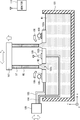
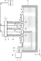
- Fig. 1 is a cross section schematically showing a free casting apparatus according to a first exemplary embodiment
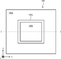
- Fig. 2 is a plane view of a shape defining member 102 according to the first exemplary embodiment
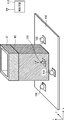
- Fig. 3 is a perspective view schematically showing a part of a free casting apparatus according to the first exemplary embodiment
- Fig. 4 is a plane view schematically showing a part of a free casting apparatus according to the first exemplary embodiment
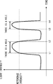
- Fig. 5 is a timing chart showing a monitoring result (intensities of light detected by an optical sensor 109) obtained by a monitor 110 disposed in a free casting apparatus according to the first exemplary embodiment
- Fig. 6 is a cross section schematically showing a modified example of the free casting apparatus according to the first exemplary embodiment
- Fig. 1 is a cross section schematically showing a free casting apparatus according to a first exemplary embodiment
- Fig. 2 is a plane view of a shape defining member 102 according to the first exemplary embodiment
- Fig. 3 is
- FIG. 7 is a perspective view schematically showing a part of the modified example of the free casting apparatus according to the first exemplary embodiment
- Fig. 8 is a cross section schematically showing a free casting apparatus according to a second exemplary embodiment
- Fig. 9 is a plane view of a shape defining member 102 according to the second exemplary embodiment
- Fig. 10 is a plane view schematically showing a part of a free casting apparatus according to the second exemplary embodiment
- Fig. 11 is a timing chart showing generation of light by light sources 108a and 108b disposed in a free casting apparatus according to the second exemplary embodiment and intensities of light detected by optical sensors 109a and 109b disposed in the free casting apparatus
- Fig. 1 shows a right-hand xyz-coordinate system for explaining a positional relation among components.
- the xy-plane forms a horizontal plane and the z-axis direction is the vertical direction. More specifically, the positive direction on the z-axis is the vertically upward direction.
- the shape in the longitudinal direction of the cast metal M3 can be arbitrarily changed by pulling up the starter ST and/or the cast metal M3 while moving the pulling-up machine 107 in a horizontal direction (x-axis direction and/or y-axis direction). Note that the shape in the longitudinal direction of the cast metal M3 may be arbitrarily changed by moving the shape defining member 102 in a horizontal direction instead of moving the pulling-up machine 107 in a horizontal direction.
- the optical sensor 109b detects light having an intensity equal to or greater than the reference intensity during the time t2 to t3. In this case, it is determined that there is a hole in the partition wall F4 of the cast metal M3 located between the light source 108b, which has emitted light during the time t1 to t3, and the optical sensor 109, which has detected the light.
Landscapes
- Engineering & Computer Science (AREA)
- Mechanical Engineering (AREA)
- Analytical Chemistry (AREA)
- Health & Medical Sciences (AREA)
- Life Sciences & Earth Sciences (AREA)
- Chemical & Material Sciences (AREA)
- Physics & Mathematics (AREA)
- Biochemistry (AREA)
- General Health & Medical Sciences (AREA)
- General Physics & Mathematics (AREA)
- Immunology (AREA)
- Pathology (AREA)
- Textile Engineering (AREA)
- Continuous Casting (AREA)
- Investigating Materials By The Use Of Optical Means Adapted For Particular Applications (AREA)
Abstract
A pulling-up-type continuous casting apparatus according to an aspect of the present invention includes a molten-metal holding furnace (101) that holds molten metal (M1), a shape defining member (102) disposed above a molten-metal surface of the molten metal (M1), the shape defining member (102) being configured to define a cross-sectional shape of a cast-metal article (M3) to be cast as the held molten metal (M1) drawn from the molten-metal surface passes through the shape defining member (102), a light source (108) that emits light, an optical sensor (109) that detects the light, the optical sensor (109) being disposed to be opposed to the light source (108) with the cast-metal article (M3) interposed therebetween, and a monitor (110) that determines that there is a hole in the cast-metal article (M3) when an intensity of the light detected by the optical sensor (109) is equal to or greater than a reference intensity.
Description
The present invention relates to a pulling-up-type continuous casting apparatus and a pulling-up-type continuous casting method.
Patent Literature 1 proposes a free casting method as a revolutionary pulling-up-type continuous casting method that does not requires any mold. As shown in Patent Literature 1, after a starter is submerged under the surface of a melted metal (molten metal) (i.e., molten-metal surface), the starter is pulled up, so that some of the molten metal follows the starter and is drawn up by the starter by the surface film of the molten metal and/or the surface tension. Note that it is possible to continuously cast a cast-metal article having a desired cross-sectional shape by drawing the molten metal and cooling the drawn molten metal through a shape defining member disposed in the vicinity of the molten-metal surface.
In the ordinary continuous casting method, the shape in the longitudinal direction as well as the shape in cross section is defined by the mold. In the continuous casting method, in particular, since the solidified metal (i.e., cast-metal article) needs to pass through the inside of the mold, the cast-metal article has such a shape that it extends in a straight-line shape in the longitudinal direction.
In contrast to this, the shape defining member used in the free casting method defines only the cross-sectional shape of the cast-metal article, while it does not define the shape in the longitudinal direction. As a result, cast-metal articles having various shapes in the longitudinal direction can be produced by pulling up the starter while moving the starter (or the shape defining member) in a horizontal direction. For example, Patent Literature 1 discloses a hollow cast-metal article (i.e., a pipe) having a zigzag shape or a helical shape in the longitudinal direction rather than the straight-line shape.
In contrast to this, the shape defining member used in the free casting method defines only the cross-sectional shape of the cast-metal article, while it does not define the shape in the longitudinal direction. As a result, cast-metal articles having various shapes in the longitudinal direction can be produced by pulling up the starter while moving the starter (or the shape defining member) in a horizontal direction. For example, Patent Literature 1 discloses a hollow cast-metal article (i.e., a pipe) having a zigzag shape or a helical shape in the longitudinal direction rather than the straight-line shape.
[PTL 1]:Japanese Unexamined Patent Application Publication No. 2012-61518
The present inventors have found the following problem.
In the free casting method disclosed in Patent Literature 1, an unintended hole(s) could be formed in the cast-metal article during the casting process depending on the starter pulling-up speed, the cast-metal article cooling condition, and so on. However, since there is no means for automatically finding a hole formed in the cast-metal article in the free casting method disclosed in Patent Literature 1, it is necessary to visually check whether there is any hole in the cast-metal article or not. As a result, in the free casting method disclosed in Patent Literature 1, there is a problem that there could be a waste of casting time and waste of raw material due to the overlooking of a hole and, as a result, the productivity of cast-metal articles could deteriorate.
In the free casting method disclosed in Patent Literature 1, an unintended hole(s) could be formed in the cast-metal article during the casting process depending on the starter pulling-up speed, the cast-metal article cooling condition, and so on. However, since there is no means for automatically finding a hole formed in the cast-metal article in the free casting method disclosed in Patent Literature 1, it is necessary to visually check whether there is any hole in the cast-metal article or not. As a result, in the free casting method disclosed in Patent Literature 1, there is a problem that there could be a waste of casting time and waste of raw material due to the overlooking of a hole and, as a result, the productivity of cast-metal articles could deteriorate.
The present invention has been made in view of the above-described problem, and an object thereof is to provide a pulling-up-type continuous casting apparatus and a pulling-up-type continuous casting method capable of improving the productivity of cast-metal articles.
A pulling-up-type continuous casting apparatus according to an aspect of the present invention includes: a holding furnace that holds molten metal; and a shape defining member disposed above a molten-metal surface of the molten metal, the shape defining member being configured to define a cross-sectional shape of a cast-metal article to be cast as the molten metal drawn from the molten-metal surface passes through the shape defining member, in which the pulling-up-type continuous casting apparatus further includes: a signal source that emits a signal, the signal being able to propagate though space, propagation of the signal being suppressed by the cast-metal article; a sensor that detects the signal, the sensor being disposed to be opposed to the signal source with the cast-metal article interposed therebetween; and determination means for determining that there is a hole in the cast-metal article only when an intensity of the signal detected by the sensor is equal to or greater than a reference intensity. As a result, it is possible to automatically determine whether there is a hole in a cast-metal article or not during the casting process and thereby to improve the productivity of cast-metal articles.
A pulling-up-type continuous casting method according to an aspect of the present invention is a pulling-up-type continuous casting method for casting a cast-metal article by drawing molten metal from a molten-metal surface of molten metal held in a holding furnace and making the drawn molten metal pass through a shape defining member, including, during a casting process: detecting a signal through the cast-metal article, the signal being able to propagate though space, propagation of the signal being suppressed by the cast-metal article; and determining that there is a hole in the cast-metal article only when an intensity of the detected signal is equal to or greater than a reference intensity. As a result, it is possible to automatically determine whether there is a hole in a cast-metal article or not during the casting process and thereby to improve the productivity of cast-metal articles.
According to the present invention, it is possible to provide a pulling-up-type continuous casting apparatus and a pulling-up-type continuous casting method capable of improving the productivity of cast-metal articles.
Specific exemplary embodiments to which the present invention is applied are explained hereinafter in detail with reference to the drawings. However, the present invention is not limited to exemplary embodiments shown below. Further, the following descriptions and the drawings are simplified as appropriate for clarifying the explanation.
<First exemplary embodiment>
Firstly, a free casting apparatus (pulling-up-type continuous casting apparatus) according to a first exemplary embodiment is explained with reference to Fig. 1. Fig. 1 is a cross section schematically showing a free casting apparatus according to the first exemplary embodiment. As shown in Fig. 1, the free casting apparatus according to the first exemplary embodiment includes a molten-metal holding furnace (holding furnace) 101, an outer-shape defining member 102a, an inner-shape defining member 102b, support rods 103 and 104, an actuator 105, a cooling gas nozzle (cooling unit) 106, a pulling-up machine 107, light sources 108, an optical sensor 109, and a monitor (determination means) 110.
For the sake of convenience, Fig. 1 shows a right-hand xyz-coordinate system for explaining a positional relation among components. In Fig. 1, the xy-plane forms a horizontal plane and the z-axis direction is the vertical direction. More specifically, the positive direction on the z-axis is the vertically upward direction.
Firstly, a free casting apparatus (pulling-up-type continuous casting apparatus) according to a first exemplary embodiment is explained with reference to Fig. 1. Fig. 1 is a cross section schematically showing a free casting apparatus according to the first exemplary embodiment. As shown in Fig. 1, the free casting apparatus according to the first exemplary embodiment includes a molten-metal holding furnace (holding furnace) 101, an outer-
For the sake of convenience, Fig. 1 shows a right-hand xyz-coordinate system for explaining a positional relation among components. In Fig. 1, the xy-plane forms a horizontal plane and the z-axis direction is the vertical direction. More specifically, the positive direction on the z-axis is the vertically upward direction.
The molten-metal holding furnace 101 contains molten metal M1 such as aluminum or its alloy, and maintains the molten metal M1 at a predetermined temperature (e.g., about 720 degrees C) at which the molten metal M1 has fluidity. In the example shown in Fig. 1, since the molten-metal holding furnace 101 is not replenished with molten metal during the casting process, the surface of molten metal M1 (i.e., molten-metal surface) is lowered as the casting process advances. Alternatively, the molten-metal holding furnace 101 may be replenished with molten metal as required during the casting process so that the molten-metal surface is kept at a fixed level. Note that the position of the solidification interface SIF can be raised by increasing the setting temperature of the molten-metal holding furnace 101 and the solidification interface SIF can be lowered by lowering the setting temperature of the molten-metal holding furnace 101. Needless to say, the molten metal M1 may be a metal other than aluminum and an alloy thereof.
The outer-shape defining member 102a and the inner-shape defining member 102b are made of ceramic or stainless, for example, and disposed above the molten metal M1. The outer-shape defining member 102a defines the outer cross-sectional shape of cast metal M3 to be cast and the inner-shape defining member 102b defines the inner cross-sectional shape of the cast metal M3 to be cast. The cast metal M3 shown in Fig. 1 is a hollow cast-metal article having a ring shape in a horizontal cross section (hereinafter referred to as "lateral cross section") (that is, the cast metal M3 shown in Fig. 1 is a pipe). In other words, the cast metal M3 shown in Fig. 1 is a hollow cast-metal article having a through-hole extending from the top surface to the bottom surface.
In the example shown in Fig. 1, the outer-shape defining member 102a and the inner-shape defining member 102b are disposed so that their bottom-side main surfaces (bottom surfaces) are in contact with the molten-metal surface. This configuration prevents oxide films formed on the surface of the molten metal M1 and foreign substances floating on the surface of the molten metal M1 from entering the cast metal M3. Alternatively, the outer-shape defining member 102a and the inner-shape defining member 102b may be disposed so that their bottom surfaces are not in contact with the molten-metal surface. Specifically, the outer-shape defining member 102a and the inner-shape defining member 102b may be disposed so that their bottom surfaces are a predetermined distance (e.g., about 0.5 mm) away from the molten-metal surface. This configuration reduces the thermal deformation and the erosion of the outer-shape defining member 102a and the inner-shape defining member 102b, thus improving their durability.
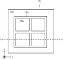
Fig. 2 is a plane view of the outer-shape defining member 102a and the inner-shape defining member 102b. Note that the cross section of the outer-shape defining member 102a and the inner-shape defining member 102b shown in Fig. 1 corresponds to a cross section taken along the line I-I in Fig. 2. As shown in Fig. 2, the outer-shape defining member 102a has, for example, a rectangular shape as viewed from the top, and has a rectangular opening at the center. The inner-shape defining member 102b has a rectangular shape as viewed from the top, and is disposed at the center of the opening of the outer-shape defining member 102a. The gap between the outer-shape defining member 102a and the inner-shape defining member 102b serves as a molten-metal passage section 102c through which molten metal passes. In this manner, the outer-shape defining member 102a, the inner-shape defining member 102b, and the molten-metal passage section 102c constitute a shape defining member 102. Note that the xyz-coordinate system shown in Fig. 2 corresponds to that shown in Fig. 1.
The pulling-up machine 107 grasps a starter (drawing member) ST, and submerges the starter ST into the molten metal M1 and/or pulls up the submerged starter ST from the molten metal M1.
As shown in Fig. 1, after the molten metal M1 adheres to the submerged starter ST, the molten metal M1 follows the starter ST and is pulled up by the starter ST while maintaining its outer shape by its surface film and/or the surface tension. Further, the molten metal M1 passes through the molten-metal passage section 102c. As the molten metal M1 passes through the molten-metal passage section 102c, an external force(s) is applied from the shape defining member 102 to the molten metal M1 and the cross-sectional shape of the held molten metal M2 is thereby defined. Note that the molten metal that follows the starter ST (or the cast metal M3 that is formed as the molten metal M1 that follows and is pulled up by the starter ST solidifies) and is pulled up from the molten-metal surface by the surface film of the molten metal M1 and/or the surface tension is called "held molten metal M2". Further, the boundary between the cast metal M3 and the held molten metal M2 is the solidification interface SIF.
The starter ST is made of, for example, ceramic or stainless. Note that the surface of the starter ST may be covered with a protection film such as a salt crystal film. In this way, the melt bonding between the starter ST and the molten metal M1 is suppressed, thereby improving the removal property between the starter ST and the cast metal M3. As a result, the starter ST can be reused. Further, when the surface of the starter ST is covered with a protection film, the starter ST may have unevenness on its surface. This facilitates the adhesion (precipitation) of a protection film on the surface of the starter ST, thus improving the removal property between the starter ST and the cast metal M3 even further. At the same time, the bonding force between the starter ST and the molten metal M1 in the pulling-up direction at the time when the molten metal is drawn can also be improved.
The support rods 103 and 104 support the outer-shape defining member 102a and the inner-shape defining member 102b, respectively. It should be noted that the support rod 104 may have a pipe structure so that a cooling gas can be fed through the the support rod 104, and an air outlet may be formed in the inner-shape defining member 102b. By using this configuration, it is possible to cool the cast metal M3 from the inside in addition to from the outside.
Both the support rods 103 and 104 are connected to the actuator 105. The actuator 105 can move the outer-shape defining member 102a and the inner-shape defining member 102b in the up/down direction (z-axis direction) through the support rods 103 and 104, respectively. In this manner, it is possible to move the shape defining member 102 downward as the molten-metal surface is lowered due to the advance of the casting process.
The cooling gas nozzle 106 sprays a cooling gas (such as air, nitrogen, and argon) on the starter ST and/or the cast metal M3, and thereby cools the starter ST and/or the cast metal M3. The position of the solidification interface SIF can be lowered by increasing the flow rate of the cooling gas and the position of the solidification interface SIF can be raised by reducing the flow rate of the cooling gas. Note that the cooling gas nozzle 106 can also be moved in the up/down direction (z-axis direction) and the horizontal direction (x-axis direction and/or y-axis direction). Therefore, for example, it is possible to move the cooling gas nozzle 106 downward in conformity with the downward movement of the shape defining member 102 as the molten-metal surface is lowered due to the advance of the casting process. Alternatively, the cooling gas nozzle 106 can be moved in a horizontal direction in conformity with the horizontal movement of the pulling-up machine 107.
By cooling the starter ST and/or the cast metal M3 by the cooling gas while pulling up the cast metal M3 by using the pulling-up machine 107 connected to the starter ST, the held molten metal M2 located in the vicinity of the solidification interface SIF is successively solidified from its upper side (the positive side in the z-axis direction) toward its lower side (the negative side in the z-axis direction) and the cast metal M3 is formed. The position of the solidification interface SIF can be raised by increasing the pulling-up speed of the pulling-up machine 107 and the position of the solidification interface SIF can be lowered by reducing the pulling-up speed. Further, the shape in the longitudinal direction of the cast metal M3 can be arbitrarily changed by pulling up the starter ST and/or the cast metal M3 while moving the pulling-up machine 107 in a horizontal direction (x-axis direction and/or y-axis direction). Note that the shape in the longitudinal direction of the cast metal M3 may be arbitrarily changed by moving the shape defining member 102 in a horizontal direction instead of moving the pulling-up machine 107 in a horizontal direction.
The light sources 108 emit light. The optical sensor 109 detects the light. Specifically, the optical sensor 109 detects the light that is emitted from the light sources 108 in a state where the cast metal M3 is interposed between the light sources 108 and the the optical sensor 109.
Figs. 3 and 4 are a perspective view and a plane view, respectively, schematically showing a part of the free casting apparatus according to this exemplary embodiment. In Fig. 3, only the shape defining member 102, the light sources 108, the optical sensor 109, the monitor 110, the starter ST, and the cast metal M3 are shown. In Fig. 4, only the light sources 108, the optical sensor 109, and the cast metal M3 are shown. Note that the xyz-coordinate systems shown in Figs. 3 and 4 correspond to that shown in Fig. 1.
As shown in Figs. 3 and 4, four light sources 108 are arranged so as to surround the outer circumference of the cast metal M3 in this exemplary embodiment. In other words, the four light sources 108 are arranged so that they emit light from the outside of the square tubular-shaped cast metal M3 toward its four sidewalls. Further, one optical sensor 109 is disposed inside the tube of the square tubular-shaped cast metal M3 in this exemplary embodiment. In other words, the one optical sensor 109 is disposed so as to be opposed to the four light sources 108 with the cast metal M3 interposed therebetween.
For example, when there is a hole in a sidewall of the cast metal M3, light that is emitted from the outside of the cast metal M3 passes through that hole and enters the inside of the cast metal M3. As a result, the optical sensor 109 detects light having an intensity equal to or greater than a reference intensity. On the other hand, when there is no hole in the sidewall of the cast metal M3, the light does not enter the inside of the cast metal M3 from the outside. Therefore, the optical sensor 109 does not detect light having an intensity equal to or greater than the reference intensity.
The monitor (determination means) 110 monitors the intensity of the light detected by the optical sensor 109 during the casting process. Further, the monitor 110 determines whether there is a hole(s) in the cast metal M3 or not based on the monitoring result.
Fig. 5 is a timing chart showing a monitoring result (intensities of light detected by the optical sensor 109) obtained by the monitor 110. For example, the monitor 110 determines that there is a hole in the cast metal M3 when the light intensity detected by the optical sensor 109 is equal to or greater than a reference intensity (time t1-t2 and time t3-t4), and determines that there is no hole in the cast metal M3 when the light intensity is less than the reference intensity.
Further, the monitor 110 determines that the hole is large in the longitudinal direction (z-axis direction) when the period during which the light intensity detected by the optical sensor 109 is continuously equal to or greater than the reference intensity is long, and determines that the hole is small in the longitudinal direction (z-axis direction) when the period during which the light intensity is continuously equal to or greater than the reference intensity is short. Further, in the case where the light intensity detected by the optical sensor 109 is equal to or greater than the reference intensity, the monitor 110 determines that the hole is large in the lateral direction (x-axis direction and/or y-axis direction) when that light intensity is strong, and determines that the hole is small in the lateral direction (x-axis direction and/or y-axis direction) when that light intensity is weak. That is, the monitor 110 can not only determine the presence of a hole(s) in the cast metal M3 but also determine the size of the hole(s) in the cast metal M3.
The monitor 110 is connected to the optical sensor 109 through a wire. In this exemplary embodiment, the optical sensor 109 is disposed inside the tube of the cast metal M3 by suspending it from the vicinity of the pulling-up machine 107 by using a wire. In this way, it is possible to prevent the wire from coming into contact with the cast metal M3.
Note that the light sources 108 and the optical sensor 109 are preferably disposed in places as close to the shape defining member 102 as possible and thus as low as possible. As a result, it is possible to find out whether there is a hole in the cast metal M3 or not in an early stage.
Next, a free casting method according to this exemplary embodiment is explained with reference to Fig. 1. Firstly, the starter ST is lowered by the pulling-up machine 107 and made to pass through the molten-metal passage section 102c between the outer-shape defining member 102a and the inner-shape defining member 102b, and the tip (bottom) of the starter ST is submerged into the molten metal M1.
Next, the starter ST starts to be pulled up at a predetermined speed. Note that even when the starter ST is pulled away from the molten-metal surface, the molten metal M1 follows the starter ST and is pulled up (drawn) from the molten-metal surface by the surface film and/or the surface tension. Further, the pulled-up molten metal M1 forms held molten metal M2. As shown in Fig. 1, the held molten metal M2 is formed in the molten-metal passage section 102c. That is, the held molten metal M2 is shaped into a given shape by the shape defining member 102.
Next, the starter ST and the cast metal M3 are cooled by a cooling gas sprayed from the cooling gas nozzle 106. As a result, the held molten metal M2 is indirectly cooled and successively solidifies from its upper side toward its lower side and hence the cast metal M3 grows. In this manner, it is possible to continuously cast the cast metal M3.
In this process, when there is a hole in a sidewall of the cast metal M3 during the casting process, the optical sensor 109, which is disposed to be opposed to the light sources 108 with the cast metal M3 interposed therebetween, detects light that is emitted from the light source 108 and passes though that hole as light having an intensity equal to or greater than a reference intensity. The monitor 110 monitors the intensity of the light detected by the optical sensor 109. Further, when the light intensity is equal to or greater than the reference intensity, the monitor 110 determines that there is a hole in the cast metal M3. As an example operation, when the monitor 110 determines that there is a hole in the cast metal M3, the casting of the cast metal is stopped.
As described above, the free casting apparatus according to this exemplary embodiment detects light emitted from the light source 108 by using the optical sensor 109 in the state where the cast metal M3 is interposed between the light sources 108 and the optical sensor 109. By doing so, the free casting apparatus according to this exemplary embodiment can automatically determine whether or not there is a hole(s) in the cast metal M3 during the casting process. As a result, the overlooking of a hole, which could occur in the case of visual checks, does not occur, thus reducing the waste of casting time and waste of raw material. Further, by finding a hole during the casting process, the casting of the cast metal can be stopped before the completion of the casting, thus further reducing the waste of casting time and the waste of raw material. As a result, the free casting apparatus according to this exemplary embodiment can improve the productivity of cast-metal articles.
Although an example in which the light sources 108 are disposed outside the cast metal M3 and the optical sensor 109 is disposed inside the cast metal M3 is explained in this exemplary embodiment, the present invention is not limited to this configuration. A light source(s) 108 may be disposed inside the cast metal M3 and an optical sensor(s) 109 may be disposed outside the cast metal M3.
Further, although an example in which the cast metal M3 is a hollow cast-metal article is explained in this exemplary embodiment, the present invention is not limited to this example. The cast metal M3 may be a solid cast-metal article having a circular or rectangular shape in a lateral cross section. In this case, it is possible to determine whether or not there is a hole in the solid cast metal by disposing a light source(s) 108 and an optical sensor(s) 109 so that they are opposed to each other with the solid cast metal interposed therebetween.
Further, although an example in which the optical sensor 109 is connected to the monitor 110 through a wire is explained in this exemplary embodiment, the present invention is not limited to this configuration. A configuration in which the optical sensor 109 wirelessly communicates with the monitor 110 may be used. Such a configuration is briefly explained hereinafter with reference to Figs. 6 and 7.
Fig. 6 is a cross section schematically showing a modified example of the free casting apparatus according to this exemplary embodiment. Fig. 7 is a perspective view schematically showing a part of the modified example of the free casting apparatus according to this exemplary embodiment. Figs. 6 and 7 correspond to Figs. 1 and 3, respectively. Note that the xyz-coordinate systems shown in Figs. 6 and 7 correspond to that shown in Fig. 1.
As shown in Figs. 6 and 7, the optical sensor 109 wirelessly communicates with the monitor 110. Further, in the examples shown in Figs. 6 and 7, four light sources 108 and one optical sensor 109 are disposed above the top surface of the shape defining member 102 with insulating material interposed therebetween. The other configuration of the free casting apparatus shown in Figs. 6 and 7 is similar to that of the free casting apparatus shown in Figs. 1 and 3, and therefore its explanation is omitted. With this configuration, no wire comes into contact with the cast metal M3, thus improving the casting flexibility.
<Second exemplary embodiment>
Fig. 8 is a cross section schematically showing a free casting apparatus according to a second exemplary embodiment. The shape of theshape defining member 102 of the free casting apparatus shown in Fig. 8 is different from that of the shape defining member 102 of the free casting apparatus shown in Fig. 1. Further, the positions of the light source(s) 108 and the optical sensor(s) 109 in Fig. 8 are different from those in Fig. 1. The other configuration of the free casting apparatus shown in Fig. 8 is similar to that of the free casting apparatus shown in Fig. 1, and therefore its explanation is omitted.
Fig. 8 is a cross section schematically showing a free casting apparatus according to a second exemplary embodiment. The shape of the
Fig. 9 is a plane view of a shape defining member 102 according to this exemplary embodiment. Note that the cross section of the shape defining member 102 shown in Fig. 8 corresponds to a cross section taken along the line II-II in Fig. 9. As shown in Fig. 9, the outer-shape defining member 102a has, for example, a rectangular shape as viewed from the top, and has a rectangular opening at the center. The inner-shape defining member 102b is composed of four members each having a rectangular shape as viewed from the top. These four members are disposed in the opening of the outer-shape defining member 102a and arranged in a matrix pattern with predetermined intervals therebetween. The gap between the outer-shape defining member 102a and the inner-shape defining member 102b serves as a molten-metal passage section 102c through which molten metal passes. In this manner, the outer-shape defining member 102a, the inner-shape defining member 102b, and the molten-metal passage section 102c constitute the shape defining member 102. Note that the xyz-coordinate system shown in Fig. 9 corresponds to that shown in Fig. 8.
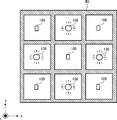
The free casting apparatus according to this exemplary embodiment performs casting by using the shape defining member 102 shown in Fig. 9, and thereby casts a hollow cast-metal article M3 whose horizontal cross-sectional (lateral cross-sectional) shape includes a plurality of openings. That is, the free casting apparatus according to this exemplary embodiment performs casting by using the shape defining member 102 shown in Fig. 9, and thereby casts a hollow cast-metal article M3 including partition walls (ribs) inside thereof. In other words, the free casting apparatus according to this exemplary embodiment performs casting by using the shape defining member 102 shown in Fig. 9, and thereby casts a hollow cast-metal article M3 including a plurality of through-holes (four through-holes in this example) extending from the top surface to the bottom surface thereof.
Next, the positional relation between the light sources 108 and the optical sensors 109 is explained with reference to Fig. 10. Fig. 10 is a plane view schematically showing a part of the free casting apparatus according to this exemplary embodiment. In Fig. 4, only the light sources 108, the optical sensors 109, and the cast metal M3 are shown. Note that the xyz-coordinate system shown in Fig. 10 corresponds to that shown in Fig. 8.
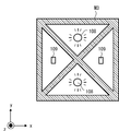
As shown in Fig. 10, two light sources 108 (hereinafter referred to as " light sources 108a and 108b") and two optical sensors 109 (hereinafter referred to as " optical sensors 109a and 109b") are provided in this exemplary embodiment. The light source 108a and the optical sensor 109a are disposed to be opposed to each other with a partition wall F1 interposed therebetween. The light source 108a and the optical sensor 109b are disposed to be opposed to each other with a partition wall F2 interposed therebetween. The light source 108b and the optical sensor 109a are disposed to be opposed to each other with a partition wall F3 interposed therebetween. The light source 108b and the optical sensor 109b are disposed to be opposed to each other with a partition wall F4 interposed therebetween.
With this configuration, it is possible to determine whether or not there is a hole in the partition wall F1 of the cast metal M3 by using the light source 108a and the optical sensor 109a. It is possible to determine whether or not there is a hole in the partition wall F2 of the cast metal M3 by using the light source 108a and the optical sensor 109b. It is possible to determine whether or not there is a hole in the partition wall F3 of the cast metal M3 by using the light source 108b and the optical sensor 109a. It is possible to determine whether or not there is a hole in the partition wall F4 of the cast metal M3 by using the light source 108b and the optical sensor 109b.
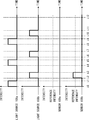
Fig. 11 is a timing chart showing generation of light by the light sources 108a and 108b and intensities of light detected by the optical sensors 109a and 109b. In the example shown in Fig. 11, the light source 108a emits light during a time t0 to t1, during a time t4 to t5, and during a time t8 to t9. The light source 108b emits light during a time t2 to t3, during a time t6 to t7, and during a time t10 to t11. The optical sensor 109a does not detect any light having an intensity equal to or greater than a reference intensity during the time t0 to t12. In contrast to this, the optical sensor 109b detects light having an intensity equal to or greater than the reference intensity during the time t2 to t3. In this case, it is determined that there is a hole in the partition wall F4 of the cast metal M3 located between the light source 108b, which has emitted light during the time t1 to t3, and the optical sensor 109, which has detected the light.
As described above, the free casting apparatus according to this exemplary embodiment can provide advantageous effects similar to those provided by the free casting apparatus according to the first exemplary embodiment. Further, when a hallow cast-metal article M3 having a partition wall(s) inside thereof is cast, it is possible to determine whether or not there is a hole in the partition wall of the hollow cast-metal article M3, which cannot be visually checked from the outside of the cast-metal article M3, by disposing a light source(s) 108 and an optical sensor(s) 109 inside of the cast-metal article M3 so that they are opposed to each other with the partition wall interposed therebetween.
Note that as shown in plane views shown in Figs. 12 to 14, there are no restrictions on the positions of the light source(s) 108 and the optical sensor(s) 109, and on the cross-sectional shape of the through-hole(s) and the number of through-holes (the shape of the opening(s) as viewed from the top and the number of the openings) of the cast-metal article M3.
Further, similar to the first exemplary embodiment, the optical sensor 109 may wirelessly communicate with the monitor 110 in this exemplary embodiment. With this configuration, no wire comes into contact with the cast metal M3, thus improving the casting flexibility.
As described above, the free casting apparatuses according to the above-described first and second exemplary embodiments detect light emitted from the light source 108 by using the optical sensor 109 in the state where the cast metal M3 is interposed between the light sources 108 and the optical sensor 109, and thereby can automatically determine whether or not there is a hole(s) in the cast metal M3 during the casting process. As a result, the overlooking of a hole, which could occur in the case of visual checks, does not occur, thus reducing the wasted casting time and the wasted raw material. Further, by finding a hole during the casting process, the casting of the cast metal can be stopped before the completion of the casting, thus further reducing the waste of casting time and the waste of raw material. As a result, the free casting apparatuses according to the above-described first and second exemplary embodiments can improve the productivity of cast-metal articles. Further, the free casting apparatus according to the second exemplary embodiment can determine whether or not there is a hole in a partition wall of a cast-metal article M3, which cannot be visually checked from the outside of the cast-metal article M3.
Although examples in which a light source(s) 108 and an optical sensor(s) 109 are provided are explained in the above-described first and second exemplary embodiments, the present invention is not limited to these examples. The only requirement is that a signal source that emits a signal which can propagate through space and whose propagation is suppressed by a cast metal M3 (obstacle), and a sensor capable of receiving that signal, should be provided. For example, a radio wave source that emits a radio wave and a sensor that receives the radio wave may be provided in place of the light source 108 and the optical sensor 109. Alternatively, a sound wave source that emits a sound wave such as an ultrasound wave and a sensor that receives the sound wave may be provided.
Note that the present invention is not limited to the above-described exemplary embodiments, and various modifications can be made without departing the spirit and scope of the present invention.
This application is based upon and claims the benefit of priority from Japanese patent application No. 2013-245249, filed on November 27, 2013, the disclosure of which is incorporated herein in its entirety by reference.
100 MOLTEN METAL HOLDING FURNACE
102 SHAPE DEFINING MEMBER
102a OUTER-SHAPE DEFINING MEMBER
102b INNER-SHAPE DEFINING MEMBER
102c MOLTEN-METAL PASSAGE SECTION
103 SUPPORT ROD
104 SUPPORT ROD
105 ACTUATOR
106 COOLING GAS NOZZLE
107 PULLING-UP MACHINE
108 LIGHT SOURCE
109 OPTICAL SENSOR
110 MONITOR
F1-F4 PARTITION WALL
M1 MOLTEN METAL
M2 HELD MOLTEN METAL
M3 CAST METAL
SIF SOLIDIFICATION INTERFACE
ST STARTER
102 SHAPE DEFINING MEMBER
102a OUTER-SHAPE DEFINING MEMBER
102b INNER-SHAPE DEFINING MEMBER
102c MOLTEN-METAL PASSAGE SECTION
103 SUPPORT ROD
104 SUPPORT ROD
105 ACTUATOR
106 COOLING GAS NOZZLE
107 PULLING-UP MACHINE
108 LIGHT SOURCE
109 OPTICAL SENSOR
110 MONITOR
F1-F4 PARTITION WALL
M1 MOLTEN METAL
M2 HELD MOLTEN METAL
M3 CAST METAL
SIF SOLIDIFICATION INTERFACE
ST STARTER
Claims (9)
- A pulling-up-type continuous casting apparatus comprising:
a holding furnace that holds molten metal; and
a shape defining member disposed above a molten-metal surface of the molten metal, the shape defining member being configured to define a cross-sectional shape of a cast-metal article to be cast as the molten metal drawn from the molten-metal surface passes through the shape defining member, wherein
the pulling-up-type continuous casting apparatus further comprises:
a signal source that emits a signal, the signal being able to propagate though space, propagation of the signal being suppressed by the cast-metal article;
a sensor that detects the signal, the sensor being disposed to be opposed to the signal source with the cast-metal article interposed therebetween; and
determination means for determining that there is a hole in the cast-metal article only when an intensity of the signal detected by the sensor is equal to or greater than a reference intensity.
- The pulling-up-type continuous casting apparatus according to Claim 1, wherein the signal is one of light, a radio wave, and a sound wave.
- The pulling-up-type continuous casting apparatus according to Claim 1 or 2, wherein
the cast-metal article is a hollow cast-metal article,
the signal source is disposed in one of a place outside the hollow cast-metal article and a place inside thereof, and
the sensor is disposed in the other of the place outside the hollow cast-metal article and the place inside thereof.
- The pulling-up-type continuous casting apparatus according to Claim 1 or 2, wherein
the cast-metal article is a hollow cast-metal article including a partition wall inside thereof,
the signal source and the sensor are disposed inside the hollow cast-metal article so that they are opposed to each other with the partition wall interposed therebetween.
- A pulling-up-type continuous casting method for casting a cast-metal article by drawing molten metal from a molten-metal surface of molten metal held in a holding furnace and making the drawn molten metal pass through a shape defining member, comprising, during a casting process:
detecting a signal through the cast-metal article, the signal being able to propagate though space, propagation of the signal being suppressed by the cast-metal article; and
determining that there is a hole in the cast-metal article only when an intensity of the detected signal is equal to or greater than a reference intensity.
- The pulling-up-type continuous casting method according to Claim 5, wherein the signal is one of light, a radio wave, and a sound wave.
- The pulling-up-type continuous casting method according to Claim 5 or 6, wherein
the cast-metal article is a hollow cast-metal article, and
in the detecting the signal, the signal emitted from one of a place outside the cast-metal article and a place inside thereof is detected in the other of the place outside the hollow cast-metal article and the place inside thereof.
- The pulling-up-type continuous casting method according to Claim 5 or 6, wherein
the cast-metal article is a hollow cast-metal article comprising a partition wall inside thereof, and
in the detecting the signal, the signal emitted from inside the cast-metal article is detected through the partition wall.
- The pulling-up-type continuous casting method according to any one of Claims 5 to 8, further comprising stopping casting of the cast-metal article when it is determined that there is a hole in the cast-metal article.
Applications Claiming Priority (2)
| Application Number | Priority Date | Filing Date | Title |
|---|---|---|---|
| JP2013-245249 | 2013-11-27 | ||
| JP2013245249A JP6136892B2 (en) | 2013-11-27 | 2013-11-27 | Pull-up type continuous casting apparatus and pull-up type continuous casting method |
Publications (1)
| Publication Number | Publication Date |
|---|---|
| WO2015079614A1 true WO2015079614A1 (en) | 2015-06-04 |
Family
ID=51866292
Family Applications (1)
| Application Number | Title | Priority Date | Filing Date |
|---|---|---|---|
| PCT/JP2014/005160 Ceased WO2015079614A1 (en) | 2013-11-27 | 2014-10-10 | Pulling-up-type continuous casting apparatus and pulling-up-type continuous casting method |
Country Status (2)
| Country | Link |
|---|---|
| JP (1) | JP6136892B2 (en) |
| WO (1) | WO2015079614A1 (en) |
Cited By (1)
| Publication number | Priority date | Publication date | Assignee | Title |
|---|---|---|---|---|
| EP3106246A1 (en) * | 2015-06-15 | 2016-12-21 | Toyota Jidosha Kabushiki Kaisha | Pulling-up-type continuous casting apparatus and pulling-up-type continuous casting method |
Citations (8)
| Publication number | Priority date | Publication date | Assignee | Title |
|---|---|---|---|---|
| JPS63313643A (en) * | 1987-06-15 | 1988-12-21 | Kawasaki Steel Corp | Method for controlling perfectly solidified position in continuous casting |
| JPH02151351A (en) * | 1988-11-30 | 1990-06-11 | Kawasaki Steel Corp | On-line inspecting method for rapid cooled alloy strip |
| EP0543677A1 (en) * | 1991-11-22 | 1993-05-26 | Elkem Technology A/S | Method for detecting pinholes in continuously cast billets |
| WO2012019213A2 (en) * | 2010-08-13 | 2012-02-16 | Voestalpine Stahl Gmbh | Device, strand casting system having the device, and method for detecting at least one flaw without contact |
| WO2012035752A1 (en) * | 2010-09-17 | 2012-03-22 | Kabushiki Kaisha Toyota Chuo Kenkyusho | Free casting method, free casting apparatus, and casting |
| CN102581244A (en) * | 2012-03-02 | 2012-07-18 | 中冶连铸技术工程股份有限公司 | Online control system and control method for surface quality of continuous casting billet |
| CN102608126A (en) * | 2012-02-23 | 2012-07-25 | 中冶连铸技术工程股份有限公司 | On-line detection method and device for surface defects of high-temperature continuously cast bloom |
| WO2013136785A1 (en) * | 2012-03-16 | 2013-09-19 | Toyota Jidosha Kabushiki Kaisha | Manufacturing method of casting, manufacturing device thereof, and casting |
Family Cites Families (2)
| Publication number | Priority date | Publication date | Assignee | Title |
|---|---|---|---|---|
| JPH0342147A (en) * | 1989-07-07 | 1991-02-22 | Nippon Steel Corp | Roll type continuous casting machine |
| JP3211655B2 (en) * | 1996-03-19 | 2001-09-25 | トヨタ自動車株式会社 | Molding method and molding apparatus |
-
2013
- 2013-11-27 JP JP2013245249A patent/JP6136892B2/en not_active Expired - Fee Related
-
2014
- 2014-10-10 WO PCT/JP2014/005160 patent/WO2015079614A1/en not_active Ceased
Patent Citations (9)
| Publication number | Priority date | Publication date | Assignee | Title |
|---|---|---|---|---|
| JPS63313643A (en) * | 1987-06-15 | 1988-12-21 | Kawasaki Steel Corp | Method for controlling perfectly solidified position in continuous casting |
| JPH02151351A (en) * | 1988-11-30 | 1990-06-11 | Kawasaki Steel Corp | On-line inspecting method for rapid cooled alloy strip |
| EP0543677A1 (en) * | 1991-11-22 | 1993-05-26 | Elkem Technology A/S | Method for detecting pinholes in continuously cast billets |
| WO2012019213A2 (en) * | 2010-08-13 | 2012-02-16 | Voestalpine Stahl Gmbh | Device, strand casting system having the device, and method for detecting at least one flaw without contact |
| WO2012035752A1 (en) * | 2010-09-17 | 2012-03-22 | Kabushiki Kaisha Toyota Chuo Kenkyusho | Free casting method, free casting apparatus, and casting |
| JP2012061518A (en) | 2010-09-17 | 2012-03-29 | Toyota Central R&D Labs Inc | Free casting method, free casting apparatus, and casting |
| CN102608126A (en) * | 2012-02-23 | 2012-07-25 | 中冶连铸技术工程股份有限公司 | On-line detection method and device for surface defects of high-temperature continuously cast bloom |
| CN102581244A (en) * | 2012-03-02 | 2012-07-18 | 中冶连铸技术工程股份有限公司 | Online control system and control method for surface quality of continuous casting billet |
| WO2013136785A1 (en) * | 2012-03-16 | 2013-09-19 | Toyota Jidosha Kabushiki Kaisha | Manufacturing method of casting, manufacturing device thereof, and casting |
Cited By (1)
| Publication number | Priority date | Publication date | Assignee | Title |
|---|---|---|---|---|
| EP3106246A1 (en) * | 2015-06-15 | 2016-12-21 | Toyota Jidosha Kabushiki Kaisha | Pulling-up-type continuous casting apparatus and pulling-up-type continuous casting method |
Also Published As
| Publication number | Publication date |
|---|---|
| JP6136892B2 (en) | 2017-05-31 |
| JP2015100835A (en) | 2015-06-04 |
Similar Documents
| Publication | Publication Date | Title |
|---|---|---|
| WO2015079614A1 (en) | Pulling-up-type continuous casting apparatus and pulling-up-type continuous casting method | |
| US9427796B2 (en) | Method for continuously casting ingot made of titanium or titanium alloy | |
| US9751127B2 (en) | Pulling-up-type continuous casting apparatus and pulling-up-type continuous casting method | |
| JP2019098394A (en) | Method and device for evaluating quality of steel | |
| JP2014144484A (en) | Hoisting type continuous casting device | |
| US20160332220A1 (en) | Up-drawing continuous casting method, up-drawing continuous casting apparatus, and continuous casting | |
| JP4211548B2 (en) | Molten metal leak detection method in continuous casting of aluminum | |
| WO2015104575A1 (en) | Up-drawing continuous casting method and up-drawing continuous casting apparatus | |
| WO2015072073A1 (en) | Pulling-up-type continuous casting apparatus and pulling-up-type continuous casting method | |
| US20160052051A1 (en) | Pulling-up-type continuous casting apparatus and pulling-up-type continuous casting method | |
| AU2013319900A1 (en) | Up-drawing continuous casting apparatus and up-drawing continuous casting method | |
| US9751128B2 (en) | Pulling-up-type continuous casting apparatus and pulling-up-type continuous casting method | |
| EP3028791A1 (en) | Hoisting-type continuous casting device and hoisting-type continuous casting method | |
| US20150202681A1 (en) | Up-drawing continuous casting apparatus and up-drawing continuous casting method | |
| US20160158833A1 (en) | Pulling-up-type continuous casting method | |
| KR101400035B1 (en) | Method for producing high quality slab | |
| US20160045954A1 (en) | Pulling-up-type continuous casting apparatus and upward continuous casting method | |
| US20180221940A1 (en) | Up-drawing continuous casting method and up-drawing continuous casting apparatus | |
| US20160296999A1 (en) | Pulling-up-type continuous casting method and pulling-up-type continuous casting apparatus | |
| CN1291122A (en) | Polygonal molds for hot-top continuous casting of metallurgical products | |
| JP2015027693A (en) | Drawing type continuous casting apparatus and drawing type continuous casting method | |
| JP5994747B2 (en) | Pull-up continuous casting method and pull-up continuous casting apparatus | |
| EP3106246A1 (en) | Pulling-up-type continuous casting apparatus and pulling-up-type continuous casting method | |
| CN115943003A (en) | Detection of metal separated from casting molds | |
| KR20120110587A (en) | Apparatus for measuring vibration of continuous casting mold and method for controlling mold using the same |
Legal Events
| Date | Code | Title | Description |
|---|---|---|---|
| 121 | Ep: the epo has been informed by wipo that ep was designated in this application |
Ref document number: 14793903 Country of ref document: EP Kind code of ref document: A1 |
|
| NENP | Non-entry into the national phase |
Ref country code: DE |
|
| 122 | Ep: pct application non-entry in european phase |
Ref document number: 14793903 Country of ref document: EP Kind code of ref document: A1 |