WO2015076363A1 - Ink supply method and ink supply device - Google Patents
Ink supply method and ink supply device Download PDFInfo
- Publication number
- WO2015076363A1 WO2015076363A1 PCT/JP2014/080881 JP2014080881W WO2015076363A1 WO 2015076363 A1 WO2015076363 A1 WO 2015076363A1 JP 2014080881 W JP2014080881 W JP 2014080881W WO 2015076363 A1 WO2015076363 A1 WO 2015076363A1
- Authority
- WO
- WIPO (PCT)
- Prior art keywords
- ink
- roller
- printing
- opening amount
- roller group
- Prior art date
Links
Images


Classifications
-
- B—PERFORMING OPERATIONS; TRANSPORTING
- B41—PRINTING; LINING MACHINES; TYPEWRITERS; STAMPS
- B41F—PRINTING MACHINES OR PRESSES
- B41F31/00—Inking arrangements or devices
- B41F31/20—Ink-removing or collecting devices
-
- B—PERFORMING OPERATIONS; TRANSPORTING
- B41—PRINTING; LINING MACHINES; TYPEWRITERS; STAMPS
- B41F—PRINTING MACHINES OR PRESSES
- B41F31/00—Inking arrangements or devices
- B41F31/02—Ducts, containers, supply or metering devices
- B41F31/04—Ducts, containers, supply or metering devices with duct-blades or like metering devices
- B41F31/045—Remote control of the duct keys
-
- B—PERFORMING OPERATIONS; TRANSPORTING
- B41—PRINTING; LINING MACHINES; TYPEWRITERS; STAMPS
- B41F—PRINTING MACHINES OR PRESSES
- B41F31/00—Inking arrangements or devices
- B41F31/02—Ducts, containers, supply or metering devices
- B41F31/13—Means for driving fountain rollers
-
- B—PERFORMING OPERATIONS; TRANSPORTING
- B41—PRINTING; LINING MACHINES; TYPEWRITERS; STAMPS
- B41F—PRINTING MACHINES OR PRESSES
- B41F33/00—Indicating, counting, warning, control or safety devices
- B41F33/04—Tripping devices or stop-motions
- B41F33/10—Tripping devices or stop-motions for starting or stopping operation of damping or inking units
-
- B—PERFORMING OPERATIONS; TRANSPORTING
- B41—PRINTING; LINING MACHINES; TYPEWRITERS; STAMPS
- B41F—PRINTING MACHINES OR PRESSES
- B41F35/00—Cleaning arrangements or devices
- B41F35/06—Cleaning arrangements or devices for offset cylinders
Definitions
- the present invention relates to an ink supply method and an ink supply apparatus for supplying ink supplied to an ink fountain roller to a printing plate mounted on a plate cylinder via an ink roller group by a call operation of an ink call roller.
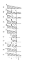
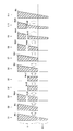
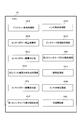
- FIG. 17 shows a main part of an inker (ink supply device) in each color printing unit in a rotary printing press.
- 1 is an ink fountain
- 2 is ink stored in the ink fountain 1
- 3 is an ink fountain roller
- 4 (4-1 to 4-n) are provided in parallel in the axial direction of the ink fountain roller 3.
- Ink fountain keys 5 is an ink calling roller
- 6 is an ink roller group
- 7 is a printing plate
- 8 is a printing cylinder on which the printing plate 7 is mounted
- 9 is a rubber cylinder (blanket cylinder)
- 10 is an impression cylinder.
- a blanket 91 is attached to the rubber cylinder 9.
- This ink supply device supplies the ink 2 in the ink fountain 1 to the ink fountain roller 3 by adjusting the opening degree of the ink fountain keys 4-1 to 4-n, and the ink supplied to the ink fountain roller 3 is supplied to the ink call roller 5.
- the ink is supplied to the printing plate 7 through the ink roller group 6 by a calling operation.
- a pattern is printed on the printing plate 7, and the ink supplied to the printing plate 7 is received by the blanket 91 on the rubber cylinder 9, and the ink received by the blanket 91 flows between the rubber cylinder 9 and the impression cylinder 10. It is transferred to printing paper (substrate) 11.
- Ink roller 6-1 to 6-4 in contact with the printing plate 7 are provided at the end of the ink flow path of the ink roller group 6. Further, the dampening water stored in the water boat 13 is supplied to the printing plate 7 through the swimsuit roller 12 together with the ink through the ink deposition rollers 6-1 to 6-4.
- the ink fountain keys 4-1 to 4-n are opened.
- the printing plate 7 in which the ink 2 in the ink fountain 1 is exchanged via the ink roller group 6 is changed to a value corresponding to the pattern of the printing plate 7 ′ of the next printing job.
- Supply to ' In this case, a trial printing is performed before the main printing, the ink supply amount is adjusted, and a satisfactory color tone is obtained.
- a desired ink film thickness distribution (gradient of ink film thickness) is created in the ink roller group 6, the plate cylinder 8 and the rubber cylinder 9.
- the ink film thickness distribution with respect to the printing plate 7 of the previous printing job remains in the ink roller group 6. ing.
- the ink film thickness distribution for the printing plate 7 of the previous printing job must be gradually changed to the ink film thickness distribution for the printing plate 7 'of the next printing job, and until a satisfactory color tone is obtained. It requires excessive adjustment of ink supply and trial printing, such as ⁇ increase in preparation time before printing '', ⁇ increase in labor load '', ⁇ waste of printing materials '', ⁇ decrease in production efficiency '', ⁇ cost increase '', etc. Problems arise.
- Patent Document 1 (reducing printing + pre-inking 2)
- the call operation of the ink call roller 5 is turned off and the printing plate 7 of the previous print job is still mounted.
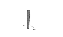
- the machine is operated to print a predetermined number of sheets (blank paper printing), thereby reducing the ink in the ink supply device (reducing printing), and it is necessary during printing that becomes thinner toward the ink roller group 6 from upstream to downstream.
- the minimum ink film thickness distribution Ma (see FIG. 18A), that is, the ink film thickness distribution Ma corresponding to the portion of the printing plate 7 having no pattern is left (ink removal).
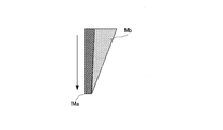
- the opening degree of the ink fountain keys 4-1 to 4-n and the rotation amount of the ink fountain roller 3 are set to values corresponding to the pattern of the printing plate 7 'of the next print job, and then the ink application roller 6-1. 6-6 is removed, the machine is operated, and the ink calling roller 5 is called a predetermined number of times, so that the minimum ink film required during printing remaining in the ink roller group 6 is obtained.
- An ink film thickness distribution Mb (see FIG. 18B) corresponding to the pattern of the printing plate 7 ′ of the next print job is superimposed on the thickness distribution Ma (pre-inking 2).
- Patent Document 2 (Turning back + Preking 1)
- the opening degree of the ink fountain keys 4-1 to 4-n is set to zero, and the ink calling roller 5 is called a predetermined number of times in this state.
- the ink on the ink roller group 6 is all returned to the ink fountain 1 (turned back). As a result, each roller in the ink roller group 6 does not hold ink.
- the opening degree of the ink fountain keys 4-1 to 4-n is set to a predetermined opening degree (for example, 50%), and the rotation amount of the ink fountain roller 3 is set to a predetermined amount (for example, 50%).
- the calling roller 5 is called a predetermined number of times to form the minimum ink film thickness distribution Ma (see FIG. 17A) required during printing in the ink roller group 6 (first step of pre-inking 1).
- the opening degree of the ink fountain keys 4-1 to 4-n and the rotation amount of the ink fountain roller 3 are set to values corresponding to the pattern of the printing plate 7 'of the next print job, and the ink application rollers 6-1 to 6-1 to 6-4 is removed, the machine is operated, and the ink call roller 5 is called a predetermined number of times, so that the minimum ink film thickness required during printing formed on the ink roller group 6 is reached.
- An ink film thickness distribution Mb (see FIG. 18B) corresponding to the pattern of the printing plate 7 ′ of the next print job is superimposed on the distribution Ma (second step of pre-inking 1).
- the blanket cleaning apparatus for example, while the cleaning cloth is intermittently running between the unwinding shaft and the winding shaft, the cleaning cloth is pressed against the blanket mounted on the rubber cylinder, The cleaning liquid is sprayed on the cleaning cloth, and the blanket is cleaned while rotating the rubber cylinder (see, for example, Patent Document 3).
- the present invention has been made to solve such a problem, and the object of the present invention is to prevent the occurrence of thin printed matter due to the influence of the cleaning liquid remaining on the blanket and eliminate the waste of printing materials. It is an object of the present invention to provide a possible ink supply method and ink supply apparatus.
- the present invention adjusts the amount of ink supplied to the ink fountain roller from the inside of the ink fountain by adjusting the opening amount of the ink fountain key, and uses the ink supplied to the ink fountain roller as the ink calling roller. After the print job is completed, the ink is supplied to the printing plate via the ink roller group by the calling operation, and the ink supplied to the printing plate is supplied to the blanket mounted on the rubber cylinder for transferring to the printing medium.
- the ink feed operation of the ink ductor roller is performed for a predetermined number of times, characterized by comprising the steps of forming a corrected ink film thickness distribution corresponding to the pattern of the printing plate of the next print job in the ink roller group.
- the opening amount of the ink fountain key is corrected according to the pattern of the printing plate of the next printing job as the opening amount corrected by the correction value of the opening amount of the ink fountain key in consideration of the effect caused by the cleaning of the blanket.
- An ink film thickness distribution is formed. Accordingly, it is possible to prevent the generation of a thin printed matter due to the influence of the cleaning liquid remaining on the blanket by supplying a little more ink.
- the ink fountain key opening amount corresponding to the printing plate pattern of the next print job is corrected by correcting the ink fountain key opening amount correction value considering the effect caused by the blanket cleaning.
- the ink calling roller is called a predetermined number of times with the ink fountain key opening amount set to the corrected opening amount, and the ink roller group corresponds to the printing plate pattern of the next print job. Since a corrected ink film thickness distribution is formed, a little more ink is supplied to prevent the generation of thin prints due to the influence of the cleaning liquid remaining on the blanket and to eliminate waste of printing materials. Is possible.
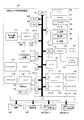
- FIG. 1 is a block diagram showing an embodiment of a print job switching control apparatus used for carrying out an ink supply method according to the present invention.
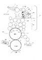
- FIG. 2 is a diagram illustrating a main part of the ink supply device in the printing unit controlled by the print job switching control device (a state in which the ink roller groups are connected (a state before the ink roller groups are divided)).
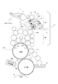
- FIG. 3 is a diagram illustrating a main part (a state in which the ink roller group is divided) of the ink supply device in the printing unit controlled by the print job switching control device.
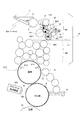
- FIG. 4 shows the main part of the ink supply device in the printing unit controlled by the print job switching control device (the state where the ink roller group is divided and the ink in the upstream roller small group is scraped off by the blade).
- FIG. 5A to 5B are diagrams showing the contents of the memory in the print job switching control apparatus.
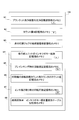
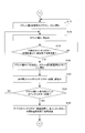
- FIG. 6 is a diagram illustrating a process of forming an ink film thickness distribution of the next print job on the ink roller group, the plate cylinder, and the rubber cylinder when the print job is switched using the print job switching control device.
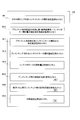
- FIG. 7 is a diagram showing a process of forming the ink film thickness distribution corresponding to FIG. 6 when the ink roller group is formed after the pre-inking in the ink apparatus and the ink film thickness distribution of the next print job is formed. It is.
- FIG. 8 is a diagram showing a process of forming the ink film thickness distribution corresponding to FIG.
- FIG. 10 is a block diagram showing an outline of the internal configuration of the ink fountain roller control device.
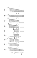
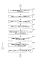
- FIG. 11 is a flowchart showing the processing operation of the ink fountain roller control device.
- FIG. 12 is a block diagram showing an outline of the internal configuration of the ink fountain key control device.
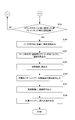
- 13A to 13B are flowcharts showing the processing operation of the ink fountain key control device.
- FIG. 14 is a block diagram showing an outline of the internal configuration of the blanket cleaning apparatus.
- 15A to 15C are flowcharts showing the processing operation of the blanket cleaning apparatus.
- FIG. 16 is a block diagram illustrating functions of main parts realized as processing operations of the CPU in the print job switching control apparatus.
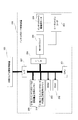
- FIG. 17 is a diagram illustrating a main part of the ink supply device in the printing unit for each color in the printing press.
- 18A to 18B are diagrams showing the ink film thickness distribution formed on the ink roller group of the ink supply device.
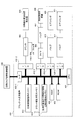
- FIG. 1 is a block diagram showing an embodiment of a print job switching control apparatus used for carrying out an ink supply method according to the present invention.
- the print job switching control apparatus 100 includes a CPU (Central Processing Unit) 101, a RAM (Random Access Memory) 102, a ROM (Read Only Memory) 103, an input device 104, a display 105, an output device ( 106), print stop switch 107, print job switching start switch 108, blanket cleaning start switch 128, blanket cleaning end switch 129, driving motor 109 of the printing press, driving motor driver 110, driving motor rotary encoder 111, D / An A converter 112, an origin position detector 113 of the printing press, a counter 114 for counting the number of rotations of the printing press, and an ink calling device 115 are provided.
- a CPU Central Processing Unit
- RAM Random Access Memory
- ROM Read Only Memory
- roller group dividing / connecting air cylinder 116 the roller group dividing / connecting air cylinder valve 117, the swimsuit roller attaching / detaching air cylinder 118, the swimsuit roller attaching / detaching air cylinder valve 119, and the ink applying roller attaching / detaching air cylinder 120.
- Ink roller attaching / detaching air cylinder valve 121 ink scraping blade attaching / detaching air cylinder 122, ink scraping blade attaching / detaching air cylinder valve 123, paper feeder 124, printing unit 125, memory 126, input / output interface ( I / O, I / F) 127-1 to 127-10.
- FIG. 2 is a diagram showing a main part of the ink supply device in each printing unit controlled by the print job switching control device 100.
- the same reference numerals as those in FIG. 17 denote the same or equivalent components as those described with reference to FIG. 17, and the description thereof will be omitted.
- the ink roller group 6 can be divided into an upstream roller subgroup 6A and a downstream roller subgroup 6B with a line L1 shown by a dotted line in the figure as a boundary.
- a roller 6C positioned between the upstream roller subgroup 6A and the downstream roller subgroup 6B is pivotally supported on one end of a swing arm 14 that swings around a fulcrum P1 as a rotation center.
- a roller group dividing / connecting air cylinder 116 is connected to the other end of the swing arm 14.
- the swing arm 14 is indicated by a one-dot chain line in order to be distinguished from others.
- the swing arm 14 swings in the direction of arrow A with the pivot point P1 as the center of rotation.
- the peripheral surface of the roller 6C is separated from the peripheral surface of the roller 6A1 positioned at the lowermost end of the ink flow path of the upstream roller subgroup 6A. Further, the peripheral surface of the roller 6C is separated from the peripheral surface of the roller 6B1 positioned at the uppermost end of the ink flow path of the downstream roller small group 6B.
- the ink roller group 6 is divided into an upstream roller small group 6A and a downstream roller small group 6B.
- the swing arm 14 swings in the direction of arrow B with the pivot point P1 as the center of rotation, and the peripheral surface of the roller 6C is moved along with this swing. It contacts the peripheral surface of the roller 6A1 located at the lowermost end of the ink flow path of the upstream roller small group 6A. Further, the circumferential surface of the roller 6C comes into contact with the circumferential surface of the roller 6B1 positioned at the uppermost end of the ink flow path of the downstream roller small group 6B (see FIG. 2). As a result, the upstream roller small group 6 ⁇ / b> A and the downstream roller small group 6 ⁇ / b> B are connected and returned to the single ink roller group 6.
- an ink scraping blade 15 that contacts the peripheral surface of the roller 6A2 of the upstream roller small group 6A and scrapes the ink in the upstream roller small group 6A, and this ink scraping
- An ink receiver 16 for collecting the ink scraped off by the take-off blade 15 is provided.
- An air cylinder 122 for attaching / detaching an ink scraping blade is provided for the ink scraping blade 15. When ink is scraped off, the ink scraper blade attaching / detaching air cylinder 122 is retracted to bring the ink scraper blade 15 into contact with the peripheral surface of the roller 6A2 (see FIG. 4). When the ink scraping blade attaching / detaching air cylinder 122 is extended, the ink scraping blade 15 is separated from the peripheral surface of the roller 6A2.
- the CPU 101 obtains various input information given via the interfaces 127-1 to 127-10, and operates according to the program stored in the ROM 103 while accessing the RAM 102 and the memory 126. .
- the driving motor rotary encoder 111 generates a rotation pulse at every predetermined rotation angle of the driving motor 109 of the printing press and outputs it to the driving motor driver 110.
- the origin position detector 113 of the printing press detects the origin position for each rotation of the printing press, generates an origin position detection signal, and outputs it to the counter 114 for counting the number of rotations of the printing press.
- the ink calling device 115 is provided for the ink calling roller 5.
- the ink calling device 115 is turned on, the calling operation of the ink calling roller 5 is started, and when the ink calling device 115 is turned off, the calling operation of the ink calling roller 5 is stopped.
- the swimsuit roller attaching / detaching air cylinder 118 is provided for the swimsuit roller 12.
- the swimsuit roller 12 When the swimsuit roller attaching / detaching air cylinder 118 is extended, the swimsuit roller 12 is in the attached state (in contact with the printing plate 7 (7 ′)), and when the swimsuit roller attaching / detaching air cylinder 118 is retracted, the swimsuit roller 12 is moved. Is in a detached state (a state separated from the printing plate 7 (7 ′)).
- the air cylinder 120 for attaching / detaching the ink application roller is provided for the ink application rollers 6-1 to 6-4.
- the ink application roller attaching / detaching air cylinder 120 is extended, the ink application rollers 6-1 to 6-4 are in the attached state (in contact with the printing plate 7 (7 ′)), and the ink applying roller attaching / detaching air cylinder 120 is attached. Is retracted, the ink application rollers 6-1 to 6-4 are in a detached state (a state separated from the printing plate 7 (7 ′)).
- the memory 126 is provided with memories M1 to M16.
- the memory M1 stores the number of cleanings X of a blanket cleaning device (described later).
- a count value N is stored in the memory M2.
- the memory M3 stores a pattern area ratio in a range corresponding to the ink fountain keys 4-1 to 4-n of the printing plate of the next print job.
- the memory M4 stores the total number n of ink fountain keys of each printing unit.
- the memory M5 stores the rotational speed Vpr of the printing press during pre-inking.
- the memory M6 stores the count value of the counter for counting the number of rotations of the printing press.
- the memory M7 stores the number of rotations N1 of the printing press at the time of ink scraping.
- the memory M8 stores a pattern area ratio-ink fountain key opening amount conversion table.
- the opening amount of the ink fountain keys 4-1 to 4-n corresponding to the pattern of the printing plate of the next print job is stored.
- the memory M10 stores a correction value conversion table of the number of cleanings of the blanket cleaning device, the pattern area ratio, and the ink fountain key opening amount.
- the memory M11 stores a correction value for the opening amount of the ink fountain keys 4-1 to 4-n after the blanket cleaning.
- the memory M12 stores the opening amount of the ink fountain keys 4-1 to 4-n at the time of pre-inking.
- the memory M13 stores the rotation amount of the ink fountain roller.
- the memory M14 stores the number of rotations N2 of the printing press during pre-inking.
- the memory M15 stores the number of rotations N3 of the printing press during plate cylinder / rubber cylinder pre-inking.
- the memory M16 stores the printing speed Vp.
- reference numeral 200 denotes an ink fountain roller control device for driving the ink fountain roller 3 in the ink supply device, and 300-1 to 300-n control opening amounts of the ink fountain keys 4-1 to 4-n in the ink supply device.
- An ink fountain key control device 400 is a blanket cleaning device.
- the blanket cleaning device 400 is provided for the rubber cylinder 9 as shown in FIG. 2, and this cleaning is performed while the cleaning cloth 401 runs intermittently between the unwinding shaft and the winding shaft in a tension state.
- the blanket 91 is washed while rotating the rubber cylinder 9 by pressing the cloth 401 against the blanket 91 attached to the rubber cylinder 9 and spraying the cleaning liquid onto the cleaning cloth 401.
- the unwinding shaft and the winding shaft are not shown.
- the ink fountain roller control device 200, the ink fountain key control devices 300-1 to 300-n, and the blanket cleaning device 400 are provided for each color ink supply device. There is one supply device. That is, the operation will be described on behalf of one ink supply device.
- Step S2 While the printing press is stopped, the printing plate 7 mounted on the plate cylinder 8 is replaced with the printing plate 7 ′ of the next printing job, and the blanket 91 on the rubber cylinder 9 is cleaned using a cleaning liquid ( FIG. 6: Step S2).
- the ink roller group 6 is divided into an upstream roller small group 6A and a downstream roller small group 6B (division during removal).
- the ink film thickness distribution Mc of the ink roller group 6 is equal to the ink film thickness distribution McA of the upstream roller small group 6A and the ink film thickness of the downstream roller small group 6B, as shown in step S3 in FIG.
- the distribution is divided into McB.
- the opening amount of the ink fountain keys 4-1 to 4-n corresponding to the pattern of the printing plate 7 ′ of the next print job is obtained, and the obtained opening amount of the ink fountain keys 4-1 to 4-n remains in the blanket 91.
- the corrected opening amount is obtained by correcting with the correction value of the opening amount of the ink fountain key in consideration of the influence of the cleaning liquid. Specifically, the opening amount of the ink fountain keys 4-1 to 4-n corresponding to the pattern of the printing plate 7 ′ of the next print job is corrected in the opening direction, and the ink fountain keys 4-1 to 4 are adjusted to the corrected opening amount. -Set the opening amount of n. Further, the upstream roller small group 6A and the downstream roller small group 6B are connected and returned to one ink roller group 6 (FIG. 6: step S5).
- the ink call roller 5 is called for the number of rotations N2 at the time of pre-inking, and the ink roller group 6 is caused to perform the next print job.
- a corrected ink film thickness distribution Md corresponding to the pattern of the printing plate 7 ′ is created (FIG. 6: step S6).
- the ink film thickness distribution Md at this time is the opening amount corrected by the opening amount of the ink fountain keys 4-1 to 4-n, that is, it is corrected in the opening direction. It is a little thicker than the ink film thickness distribution corresponding to the pattern of the printing plate 7 ′.
- the ink roller group 6 is subdivided into an upstream roller small group 6A and a downstream roller small group 6B (division at the start of printing).
- the ink film thickness distribution Md of the ink roller group 6 is set as the ink film thickness distribution MdA of the upstream roller subgroup 6A and the ink film thickness of the downstream roller subgroup 6B, as shown as step S7 in FIG.
- the distribution is divided into MdB.
- the printing press is rotated by the number of rotations N3 at the time of plate cylinder / rubber cylinder pre-inking, and the printing plate 7 ′ in which the ink in the roller group 6B on the downstream side is mounted on the plate cylinder 8 and It supplies to the rubber cylinder 9 (FIG. 6: process S9).
- the printing plate 7 ′ and the rubber cylinder 9 supplies to the rubber cylinder 9.
- only ink having a relatively thin ink film thickness distribution MdB in the roller group 6B on the downstream side is supplied to the printing plate 7 ′ and the rubber cylinder 9, and the ink film on the printing plate 7 ′ and the rubber cylinder 9 is supplied.
- the thickness distribution is prevented from becoming too thick.
- step S7 the printing cylinder 8 and the rubber cylinder 9 are put on (FIG. 7: step S7), and the printing machine is rotated a predetermined number of times to supply ink to the printing cylinder 8 and the rubber cylinder 9.
- the plate cylinder 8 and the rubber cylinder 9 since all the ink in the ink supply device is leveled in the ink roller group 6, the plate cylinder 8 and the rubber cylinder 9, a large amount of excessive ink is supplied to the plate cylinder 8 and the rubber cylinder 9.
- the ink film thickness distribution in the cylinder 8 and the rubber cylinder 9 becomes too thick (FIG. 7: step S8).
- step S6 of FIG. 6 the ink roller group 6 is divided into an upstream roller subgroup 6A and a downstream roller subgroup 6B (FIG. 6: step S7). Only the ink having a relatively thin ink film thickness distribution MdB in the roller subgroup 6B is supplied to the printing plate 7 ′ and the rubber cylinder 9 (FIG. 6: step S9), and the ink in the printing plate 7 ′ and the rubber cylinder 9 is supplied. The film thickness distribution is prevented from becoming too thick.
- step S10 the upstream roller small group 6A and the downstream roller small group 6B are reconnected and returned to one ink roller group 6 (FIG. 6: step S10), and the ink calling roller 5 is called.
- the operation is performed so that the rubber cylinder 9 is also attached to the impression cylinder 10, that is, the cylinder cylinder 8, the rubber cylinder 9 and the impression cylinder 10 are brought into contact with each other (see FIG. 2).
- the printing of the next print job using the printing plate 7 ′ mounted on is started.
- the ink film thickness distribution during the printing of the next print job (the ink film thickness distribution during the final main printing) is created during printing.
- the ink film thickness distribution MdB ′ in the roller small group 6B and the plate cylinder 8 and the rubber cylinder 9 on the downstream side is thin, the ink quickly flows from the upstream side to the downstream side, and the ink roller group 6 and the plate
- the ink film thickness distribution Me (FIG. 6: step S11) during the final printing is quickly formed on the cylinder 8 and the rubber cylinder 9.
- step S8 since the ink film thickness distribution in the plate cylinder 8 and the rubber cylinder 9 becomes too thick (FIG. 7: step S8), the ink film thickness distribution Me during the main printing (FIG. 7: step S9). It takes a long time to form a large amount of waste paper.
- step S9 since the ink film thickness distribution formed on the plate cylinder 8 and the rubber cylinder 9 is prevented from becoming too thick, the ink flows quickly from the upstream side to the downstream side. The ink film thickness distribution during the final printing is quickly formed on the roller group 6, the plate cylinder 8 and the rubber cylinder 9, and after the start of the printing of the next print job after replacing the printing plate 7 ', a short time is required. Normal printed matter can be obtained.
- the ink film thickness distribution of the upstream roller small group 6A and the downstream roller small group 6B is corrected to be slightly thicker than the ink film thickness distribution corresponding to the pattern of the printing plate 7 'of the next print job. Therefore, a little more ink is supplied to the printing plate 7 ′ and the rubber cylinder 9 in steps S9 and S10 of FIG. Thereby, generation
- the downstream side The roller small group 6B is put on the plate cylinder 8 (FIG. 6: Step S8).
- the ink roller group 6 is connected to the upstream roller small group 6A and the downstream side.
- the downstream roller small group 6B is put on the plate cylinder 8 before being divided into the roller small group 6B (FIG. 8: step S7), and then the ink roller group 6 is moved to the upstream roller small group 6A. And may be divided into a small roller group 6B on the downstream side (FIG. 8: step S8).
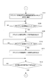
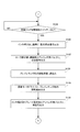
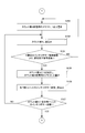
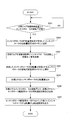
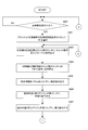
- step S101 When switching print jobs, the operator turns on the print stop switch 107. Then, the CPU 101 confirms that the print stop switch 107 is turned on (FIG. 9A: YES in step S101), outputs a paper feed stop command to the paper feeding device 124, and stops paper feeding to the printing press. At the same time (step S102), a cylinder removal command, an ink application roller removal instruction, and a swim roller removal instruction are output to the printing unit 125 (steps S103, S104, and S105).
- the rubber cylinder 9 is removed from the plate cylinder 8 and the impression cylinder 10 in accordance with the cylinder removal command.
- the ink forming rollers 6-1 to 6-4 are removed according to a command to remove the ink forming roller, and are separated from the printing plate 7.
- the swimsuit roller 12 is removed by the command to remove the swimsuit roller, and is separated from the printing plate 7.
- the CPU 101 outputs a stop signal to the driving motor driver 110 (step S106), and stops the driving motor 109. This stops the printing press (FIG. 6: step S1).
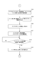
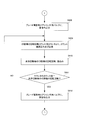
- the CPU 101 sets the cleaning frequency X of the blanket cleaning device in the memory M1 to 0 (FIG. 9B: Step S107), and waits for the operator to turn on the blanket cleaning start switch 128 (Step S108).
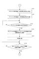
- the CPU 101 outputs a cleaning start command to the blanket cleaning device 400 until the blanket cleaning end switch 129 is turned on (YES in step S110). (Step S109).
- step S110 When the blanket cleaning end switch 129 is turned on (YES in step S110), a cleaning stop command is output to the blanket cleaning device 400 (step S111), and a blanket cleaning stop command received from the blanket cleaning device 400 is received. After confirming the completion signal (YES in step S112), the output of the cleaning stop command to the blanket cleaning device 400 is stopped (FIG. 9C: step S113).
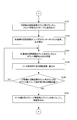
- a transmission command for the number of cleaning times is transmitted to the blanket cleaning apparatus 400 (step S114), the number of cleaning times of the blanket cleaning apparatus sent from the blanket cleaning apparatus 400 is received (step S115), and the received blanket cleaning apparatus Is written in the memory M1 as X (step S116).
- the number of times the blanket cleaning device is cleaned is the number of times that the blanket cleaning device 400 sprays the cleaning liquid and cleans the blanket 91 while the CPU 101 outputs a cleaning start command to the blanket cleaning device 400. The operation of the blanket cleaning apparatus 400 will be described later.
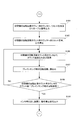
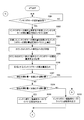
- step S1 the operator presses the printing machine mounted on the plate cylinder 8 while the printing press is stopped and the ink deposition rollers 6-1 to 6-4 and the swimsuit roller 12 are removed (FIG. 6: step S1).
- the plate 7 is replaced with a plate 7 'for the next print job (step S117).
- the CPU 101 stores the pattern area ratio in the range corresponding to the ink fountain keys 4-1 to 4-n of the printing plate 7 ′ input from the input device 104 in the memory M3.
- the measurement of the pattern area ratio in the range corresponding to the ink fountain keys 4-1 to 4-n of the printing plate 7 ′ is shown in Patent Document 5 and Patent Document 6 by the present applicant.
- the pattern area ratio measured using this “Picture Area Ratio Measuring Device” is written in a portable memory, and the portable memory in which this pattern area ratio is written is input device.
- the pattern area ratio in a range corresponding to the ink fountain keys 4-1 to 4-n of the printing plate 7 ′ is input.
- the CPU 101 and the “pattern area ratio measuring device” are connected online, and the pattern area ratio in the range corresponding to the ink fountain keys 4-1 to 4-n of the printing plate 7 ′ is directly captured from the “pattern area ratio measuring device”. You may do it.
- the portable memory When the portable memory is set in the input device 104, that is, when the picture area ratio of the printing plate 7 'in the range corresponding to the ink fountain keys 4-1 to 4-n is input (YES in step S118).
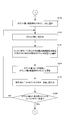
- the count value N in the memory M2 is set to 1 (FIG. 9D: Step S119), the count value N is read from the memory M2 (Step S120), and the pattern area ratio of the printing plate 7 ′ in the range corresponding to the Nth ink fountain key is obtained.
- the data is read from the portable memory and stored in the address position for the Nth ink fountain key in the memory M3 (step S121).
- step S122 1 is added to the count value N in the memory M2 (step S122), the total number n of ink fountain keys is read from the memory M4 (step S123), and the count value N exceeds the total number n of ink fountain keys (YES in step S124). ), The processing operation of steps S120 to S124 is repeated.
- the pattern area ratio in the range corresponding to the ink fountain keys 4-1 to 4-n of the printing plate 7 ′ is read from the portable memory and corresponds to the ink fountain keys 4-1 to 4-n of the next print job. It is stored in the memory M3 as the pattern area ratio of the range.
- the ink film thickness distribution Mc of the ink roller group 6 is equal to the ink film thickness distribution McA of the upstream roller small group 6A and the ink film thickness of the downstream roller small group 6B, as shown in step S3 in FIG.
- the distribution is divided into McB.
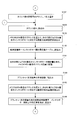
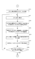
- the CPU 101 reads out the rotational speed Vpr during pre-inking from the memory M5 (step S128), and outputs the rotational speed Vpr during pre-inking to the driving motor driver 110 via the D / A converter 112 (step S129). ). As a result, the printing press starts to rotate, and its speed increases to the rotational speed Vpr during pre-inking.
- the CPU 101 outputs an arrival signal to the air cylinder valve 123 for attaching / detaching the ink scraping blade (step S130).
- the ink scraping blade attaching / detaching air cylinder 122 is retracted, the ink scraping blade 15 comes into contact with the peripheral surface of the roller 6A2, and the ink in the roller small group 6A on the upstream side. Scraping (removal of ink) is started.
- the CPU 101 continues to remove the ink in the roller group 6A on the upstream side until the number of rotations of the printing press reaches the number of rotations N1 during ink scraping in the memory M7. That is, the CPU 101 outputs an arrival signal to the air cylinder valve 123 for attaching and removing the ink scraping blade (step S130), and then outputs a reset signal and an enable signal to the counter 114 for counting the number of rotations of the printing press (FIG. 9F: In step S131, the output of the reset signal to the counter 114 for counting the number of rotations of the printing press is stopped (step S132), and the counting operation from zero of the counter for counting the number of rotations of the printing press 114 is started.
- step S133 the count value is read from the counter 114 for counting the number of rotations of the printing press and stored in the memory M6 (step S133), and the number of rotations N1 at the time of ink scraping in the memory M7 is read (step S134).
- steps S133 to S135 is repeated until the count value of the count counter 114 reaches the number of rotations N1 at the time of ink scraping (YES in step S135).
- step S4 in FIG. 6 the ink film thickness distribution McA of the roller group 6A on the upstream side becomes almost zero.
- the ink film thickness distribution of the roller group 6B on the downstream side is leveled by the number of rotations N1 at the time of ink scraping to become a flat ink film thickness distribution McB '.
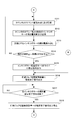
- Step S137 the CPU 101 sets the count value N in the memory M2 to 1 (FIG. 9G: Step S137), reads the count value N from the memory M2 (Step S138), and from the address position for the Nth ink fountain key in the memory M3, The pattern area ratio in the range corresponding to the Nth ink fountain key of the next print job is read (step S139).
- the pattern area ratio-ink fountain key opening amount conversion table in the memory M8 is read (step S140).
- the range corresponding to the Nth ink fountain key of the next print job is read.
- the opening amount of the Nth ink fountain key of the next print job (the opening amount of the Nth ink fountain key corresponding to the pattern of the printing plate 7 'of the next print job) is obtained, and the next print job obtained
- the opening amount of the Nth ink fountain key is stored in the address position for the Nth ink fountain key in the memory M9 (step S141).
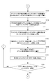
- step S142 the cleaning frequency X of the blanket cleaning device in the memory M1 is read (step S142), and the pattern area ratio in the range corresponding to the Nth ink fountain key of the next print job is read from the Nth address position of the memory M3 (step S142).
- step S143 Reading the correction value conversion table of the number of times of cleaning of the blanket cleaning device / pattern area ratio-ink fountain key opening amount in the memory M10 (step S144), and the number of cleaning times / pattern area ratio of the blanket cleaning device-correction value of ink fountain key opening amount Using the conversion table, the correction value for the opening amount of the Nth ink fountain key after blanket cleaning is obtained from the number X of cleaning times of the blanket cleaning device and the pattern area ratio in the range corresponding to the Nth ink fountain key of the next print job, It is stored in the Nth address position of the memory M11 (FIG. 9H: scan -Up S145).
- the CPU 101 reads the opening amount of the Nth ink fountain key of the next print job from the Nth address position of the memory M9 (step S146), and performs blanket cleaning to the opening amount of the Nth ink fountain key of the next print job.
- the correction value for the opening amount of the subsequent Nth ink fountain key is added to obtain the opening amount of the Nth ink fountain key at the time of pre-inking, and is stored in the Nth address position of the memory M12 (step S147). It transmits to the control apparatus 300 (step S148).
- step S149 1 is added to the count value N in the memory M2 (step S149), the total number n of ink fountain keys is read from the memory M4 (step S150), and the count value N exceeds the total number n of ink fountain keys (YES in step S151).
- steps S138 to S151 are repeated.
- the opening amount of the ink fountain key 4-1 to 4-n corresponding to the pattern of the printing plate 7 'corresponding to the ink fountain key 4-1 to 4-n is obtained, and this opening amount is the opening amount of the ink fountain key after blanket cleaning.
- step S152 sets the count value N in the memory M2 to 1 (FIG. 9I: step S152), reads the count value N from the memory M2 (step S153), and opens the ink fountain key from the Nth ink fountain key control device 300. The presence or absence of a setting completion signal is confirmed (step S154).
- step S154 if the N-th ink fountain key control device 300 has not transmitted an ink fountain key opening amount setting completion signal (NO in step S154), the process returns to step S152, and the count value N in the memory M2 is set to 1. S153 and S154 are repeated.
- step S154 If the Nth ink fountain key control device 300 has transmitted a setting completion signal of the ink fountain key opening amount (YES in step S154), 1 is added to the count value N in the memory M2 (step S155), and the memory M4 The total number n of ink fountain keys is read (step S156), and the count value N is compared with the total number n of ink fountain keys (step S157).
- the CPU 101 repeats the processing operations in steps S153 to S157 until the count value N matches the total number n of ink fountain keys.
- the CPU 101 sets the ink fountain key opening amount.
- the ink fountain key opening amount setting completion signal is transmitted to all the ink fountain key control devices 300 (300-1 to 300-n) (FIG. 9J: Step S158).
- the CPU 101 outputs a connection signal to the roller group dividing / connecting air cylinder valve 117 (step S159), connecting the upstream roller subgroup 6A and the downstream roller subgroup 6B, It returns to the ink roller group 6 (FIG. 6: process S5).
- the CPU 101 reads the rotation amount of the ink fountain roller stored in the memory M13 (step S160), and transmits the read rotation amount of the ink fountain roller to the ink fountain roller control device 200 (step S161).
- an operation signal is output to the ink call device 115 (step S163), and the ink call roller 5 is called.
- the CPU 101 continues the calling operation of the ink calling roller 5 until the number of rotations of the printing press reaches the number N2 of pre-inking rotations in the memory M14 (FIG. 9K: steps S164 to S168).
- a reset signal and an enable signal are output to the counter 114 for counting the number of rotations of the printing press (step S164), and output of the reset signal to the counter 114 for counting the number of rotations of the printing press is stopped (step S165).
- the counting operation from zero of the counter 114 for counting the number of rotations of the machine is started.
- the count value is read from the counter 114 for counting the number of rotations of the printing press and stored in the memory M6 (step S166), and the number of rotations N2 at the time of pre-inking in the memory M14 is read (step S167).
- the processing operations in steps S166 to S168 are repeated.
- step S168 When the count value of the counter 114 for counting the number of rotations of the printing press reaches the number N2 of rotations during pre-inking (YES in step S168), the CPU 101 outputs an operation stop signal to the ink calling device 115, and the ink calling roller 5 The calling operation is stopped (step S169).
- step S6 the ink film thickness distribution Md corrected according to the pattern of the printing plate 7 'of the next print job is formed on the ink roller group 6 (FIG. 6: step S6).
- step S170 sets the count value N in the memory M2 to 1 (FIG. 9L: step S170), reads the count value N from the memory M2 (step S171), and from the address position for the Nth ink fountain key in the memory M9, The opening amount of the Nth ink fountain key of the next print job is read (step S172) and transmitted to the Nth ink fountain key control device 300 (step S173).
- step S174 1 is added to the count value N in the memory M2 (step S174), the total number n of ink fountain keys is read from the memory M4 (step S175), and the count value N exceeds the total number n of ink fountain keys (YES in step S176).
- steps S171 to S176 are repeated.
- the opening degree of the ink fountain keys 4-1 to 4-n corresponding to the pattern of the printing plate 7 'of the next print job in the range corresponding to the ink fountain keys 4-1 to 4-n is changed to the ink fountain key control devices 300-1 to 300- Sent to 300-n.
- step S177 the CPU 101 sets the count value N in the memory M2 to 1 (FIG. 9M: step S177), reads the count value N from the memory M2 (step S178), and opens the ink fountain key from the Nth ink fountain key control device 300. The presence / absence of a setting completion signal is confirmed (step S179).
- step S179 if the N-th ink fountain key control device 300 has not transmitted an ink fountain key opening completion setting signal (NO in step S179), the process returns to step S177, and the count value N in the memory M2 is set to 1. S178 and S179 are repeated.
- step S179 If the Nth ink fountain key control device 300 has transmitted a setting completion signal for the ink fountain key opening amount (YES in step S179), 1 is added to the count value N in the memory M2 (step S180), and the memory M4 The total number n of ink fountain keys is read (step S181), and the count value N is compared with the total number n of ink fountain keys (step S182).
- the CPU 101 repeats the processing operations in steps S178 to S182 until the count value N matches the total number n of ink fountain keys.
- the CPU 101 sets the ink fountain key opening amount.
- the ink fountain key opening amount setting completion signal is transmitted to all the ink fountain key control devices 300 (300-1 to 300-n) (step S183).
- the ink film thickness distribution Md of the ink roller group 6 is set as the ink film thickness distribution MdA of the upstream roller subgroup 6A and the ink film thickness of the downstream roller subgroup 6B, as shown as step S7 in FIG.
- the distribution is divided into MdB.
- the CPU 101 outputs a swim roller application command, an ink application roller command, and a plate cylinder and rubber cylinder command to the printing unit 125 (steps S185, S186, S187). That is, the swimsuit roller 12 is put into contact with the printing plate 7 'in accordance with a swimsuit roller wearing command. Further, the ink application rollers 6-1 to 6-4 are attached according to the ink application roller application command and are in contact with the printing plate 7 ′. In addition, only the plate cylinder 8 and the rubber cylinder 9 are put into a wearing state in accordance with a wearing instruction for the plate cylinder and the rubber cylinder. That is, the rubber cylinder 9 is attached only to the plate cylinder 8. As a result, the small roller group 6B on the downstream side, the plate cylinder 8 and the rubber cylinder 9 are put into a worn state (FIG. 6: step S8).
- Step S188 a reset signal and an enable signal are output to the counter 114 for counting the number of rotations of the printing press
- Step S189 output of the reset signal to the counter 114 for counting the number of rotations of the printing press is stopped.
- Step S189 start the counting operation from zero of the counter 114 for counting the number of rotations of the printing press.
- the count value is read from the counter 114 for counting the number of rotations of the printing press and stored in the memory M6 (step S190), and the number N3 of rotations during plate cylinder / rubber cylinder pre-inking in the memory M15 is read (step S191).
- steps S190 to S192 are repeated until the count value of the counter 114 for counting the number of rotations of the printing press reaches the number of rotations N3 during plate cylinder / rubber cylinder pre-inking (FIG. 9O: YES in step S192).
- the ink in the roller group 6B on the downstream side is supplied to the printing plate 7 'and the rubber cylinder 9 mounted on the plate cylinder 8 (FIG. 6: step S9).
- the ink having a relatively thin ink film thickness distribution MdB in the downstream roller small group 6B is supplied to the printing plate 7 ′ and the rubber cylinder 9, and the ink film on the printing plate 7 ′ and the rubber cylinder 9 is supplied.
- the thickness distribution is prevented from becoming too thick.
- the CPU 101 outputs a connection signal to the roller group dividing / connecting air cylinder valve 117 (step S194), and reconnects the upstream roller small group 6A and the downstream roller small group 6B (FIG. 2). (See FIG. 6) Return to one ink roller group 6 (FIG. 6: Step S10).
- the CPU 101 reads out the printing speed Vp from the memory M16 (step S195), and outputs a rotation command for the printing speed Vp to the driving motor driver 110 via the D / A converter 112 (step S196). Is the printing speed Vp. Further, a paper feed command is output to the paper feeder 124 (step S197), and paper feeding to the printing press is started. Also, a cylinder insertion instruction (an instruction to attach the impression cylinder and the rubber cylinder) is output to the printing unit 125 (step S198), and the rubber cylinder 9 is also put on the impression cylinder 10.
- the cylinder cylinder 8 is in a state of being brought into contact with the plate cylinder 8, the rubber cylinder 9, and the impression cylinder 10 (see FIG. 2). As a result, printing of the next print job using the printing plate 7 ′ is started.
- the ink film thickness distribution during the printing of the next print job (the ink film thickness distribution during the final main printing) is created during printing.
- the ink film thickness distribution MdB ′ in the roller small group 6B and the plate cylinder 8 and the rubber cylinder 9 on the downstream side is thin, the ink quickly flows from the upstream side to the downstream side, and the ink roller group 6 and the plate The ink film thickness distribution Me during the main printing is quickly formed on the cylinder 8 and the rubber cylinder 9 (FIG. 6: step S11).
- FIG. 10 shows an outline of the internal configuration of the ink fountain roller control device 200.
- the ink fountain roller control device 200 includes a CPU 201, a RAM 202, a ROM 203, an ink fountain roller driving motor 204, an ink fountain roller driving motor driver 205, an ink fountain roller driving motor rotary encoder 206, an input / output interface (I / O, I / F) 207, 208 and memories 209, 210, and is connected to the print job switching control apparatus 100 via the interface 207.
- the memory 209 stores the received rotation amount of the ink fountain roller.
- the memory 210 stores a target rotation amount of the ink fountain roller.
- the CPU 201 stores the received rotation amount in the memory 209 (step S202). Also, the ink fountain roller rotation amount reception completion signal is transmitted to the print job switching control device 100 (step S203). The received rotation amount of the ink fountain roller is stored in the memory 210 as the rotation amount of the ink fountain roller (target rotation amount) (step S204). Then, the target rotation amount is read from the memory 210 (step S205), the target rotation speed of the ink fountain roller driving motor 204 is calculated from the target rotation amount (step S206), and the ink fountain roller driving motor driver 205 is calculated. The rotation amount of the feed and ink fountain roller is adjusted to the target rotation amount (step S207).
- FIG. 12 shows an outline of the internal configuration of the ink fountain key control device 300 (300-1 to 300-n).
- the ink fountain key control device 300 includes a CPU 301, a RAM 302, a ROM 303, an ink fountain key drive motor 304, an ink fountain key drive motor driver 305, an ink fountain key drive motor rotary encoder 306, a counter 307, and an input / output interface (I / O, I / F) 308. , 309 and memories 310 to 313, and connected to the print job switching control apparatus 100 via the interface 308.
- the memory 310 stores the received ink fountain key opening amount.
- the memory 311 stores a target ink fountain key opening amount.
- the memory 312 stores the count value of the counter 307.
- the memory 313 stores the current opening degree of the ink fountain key.
- the CPU 301 stores the received opening amount in the memory 310 (step S302) and receives the received ink fountain key. Is stored in the memory 311 as a target opening amount (step S303).
- the count value is read from the counter 307 and stored in the memory 312 (step S304).
- the current ink fountain key opening amount is obtained from the read count value of the counter 307 and stored in the memory 313 (step S305).
- the target ink fountain key opening amount is read from (step S306). If the current ink fountain key opening amount is the same as the target opening amount (YES in step S307), the process immediately proceeds to step S316 (FIG. 13B) to print.
- An ink fountain key opening amount setting completion signal is output to the job switching control device 100.
- step S307 If the current ink fountain key opening amount is not the same as the target opening amount (NO in step S307), the ink fountain key drive motor 304 is driven until the current ink fountain key opening amount is the same as the target opening amount. Thereafter (steps S308 to S315 (FIG. 13B)), an ink fountain key opening amount setting completion signal is output to the print job switching control device 100 (step S316).
- step S308 if the current ink fountain key opening amount is smaller than the target opening amount (YES in step S308), a forward rotation command is sent to the ink fountain key driving motor driver 305 (step S309), and the counter 307 calculates the count value. Reading (step S311), the current ink fountain key opening amount is calculated from the count value (step S312), the target ink fountain key opening amount is read from the memory 311 (step S313), and the current ink fountain key opening amount is the target. The processing operation of steps S311 to S314 is repeated until the opening degree of the ink fountain key is equal (YES in step S314).
- Step S310 If the current ink fountain key opening amount is larger than the target opening amount (NO in step S308), a reverse rotation command is sent to the ink fountain key driving motor driver 305 (step S310), and the count value is read from the counter 307. (Step S311), the current ink fountain key opening amount is calculated from the count value (Step S312), and the target ink fountain key opening amount is read from the memory 311 (Step S313). The processing operation of steps S311 to S314 is repeated until the opening degree of the ink fountain key matches (YES in step S314).
- step S314 If the current ink fountain key opening amount matches the target ink fountain key opening amount in step S314 (YES in step S314), a stop command is output to the ink fountain key driving motor driver 305 (step S315), and print job switching is performed. A setting completion signal for the ink fountain key opening amount is output to the controller 100 (step S316).
- step S316 When the ink fountain key opening amount setting completion signal is output to the print job switching control device 100 (step S316), the CPU 301 receives the ink fountain key opening amount setting completion signal from the print job switching control device 100 (step S317). YES), the output of the ink fountain key opening amount setting completion signal to the print job switching control device 100 is stopped (step S318).
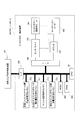
- FIG. 14 shows an outline of the internal configuration of the blanket cleaning apparatus 400.
- Blanket cleaning device 400 CPU 401, RAM 402, ROM 403, printing machine origin position detector 404, printing machine rotation count counter 405, cleaning liquid injection device 406, cleaning liquid injection nozzle valve 407, timer 408, cleaning cloth feed air Cylinder 409, cleaning cylinder feed air cylinder valve 410, blade attachment / detachment air cylinder 411, blade attachment / detachment air cylinder valve 412, memories 413 to 415, input / output interfaces (I / O, I / F) 416-1 to 416-5, and is connected to the print job switching control apparatus 100 via the interface 416-1.
- the memory 413 stores the number of cleaning times of the blanket cleaning device.
- the memory 414 stores the count value of the counter 405 for counting the number of rotations of the printing press.
- the memory 415 stores the number of rotations of the printing press for each cleaning number.
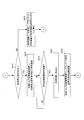
- step S401 When a cleaning start command is sent from the print job switching control device 100 (FIG. 15A: YES in step S401), the CPU 401 sets the number of cleanings in the memory 413 to 1 (step S402), and counts the rotation number of the printing press. A reset signal and an enable signal are output to 405 (step S403), output of the reset signal to the counter 405 for counting the number of rotations of the printing press is stopped (step S404), and the counter for counting the number of rotations 405 of the printing press is set to zero. The counting operation from is started.
- an injection command is output to the cleaning liquid injection nozzle valve 407 (step S405), a cloth feed command is output to the cleaning cloth feed air cylinder valve 410 (step S406), and the cleaning cloth feed air cylinder valve 410 is output.
- a return command is output (step S407), a wearing command is output to the blade mounting / removing air cylinder valve 412 (FIG. 15B: step S408), and the cleaning cloth 401 sprayed with the cleaning liquid is sent out and pressed against the blanket 91 on the rubber cylinder 9. .
- step S410 the count value is read from the counter 405 for counting the number of rotations of the printing press and stored in the memory 414 (step S409), and the number of rotations of the printing press for each cleaning number in the memory 415 is read (step S410).
- the count value of the counter 405 for counting the number of rotations is equal to the number of rotations of the printing press for each number of cleanings (YES in step S411)
- a de-command is output to the blade cylinder air cylinder valve 412 (step S412).
- the CPU 101 repeats the processing operations of steps S403 to S413 while confirming the presence or absence of a cleaning stop command from the print job switching control device 100 (FIG. 15C: step S413).
- the CPU 101 adds 1 to the number of times the blanket cleaning device has been cleaned in the memory 413 (step S414).
- step S413 If a cleaning stop command is sent from the print job switching control device 100 while the processing operations in steps S403 to S413 are repeated (YES in step S413), the CPU 101 completes reception of the cleaning stop command to the print job switching control device 100.
- a signal is transmitted (step S415), the cleaning frequency transmission command sent from the print job switching control device 100 that has received this cleaning stop command reception completion signal is received (YES in step S416), and the blanket in the memory 413 is received.
- the cleaning frequency of the cleaning device is read (step S417), and the read cleaning frequency of the blanket cleaning device is transmitted to the print job switching control device 100 (step S418).
- the step of cleaning the blanket 91 attached to the rubber cylinder 9 (steps S108 to S113) and the printing of the next print job are performed.
- a step of calculating the opening amount of the ink fountain keys 4-1 to 4-n according to the pattern of the plate 7 '(steps S139 to S141), and the calculated opening amount of the ink fountain keys 4-1 to 4-n is used to clean the blanket 91.
- Step S142 to S147 Invoking the ink calling roller 5 with the correction values taking account of the influence caused by the correction (steps S142 to S147) and the opening amount of the ink fountain keys 4-1 to 4-n being set to the corrected opening amount
- the operation is performed a predetermined number of times, and a corrected ink film thickness distribution is formed on the ink roller group 6 according to the pattern of the printing plate 7 'of the next print job. That step (Step S160 ⁇ S169) and is executed (see step S2 ⁇ S6 shown in FIG. 6).
- the opening amount of the ink fountain key 4-1 to 4-n is corrected by the correction value of the opening amount of the ink fountain key in consideration of the effect caused by the cleaning of the blanket 91.
- a corrected ink film thickness distribution corresponding to the pattern of the plate 7 ′ is formed. Due to this corrected ink film thickness distribution, a little more ink is supplied, and generation of a thin printed matter due to the influence of the cleaning liquid remaining on the blanket 91 is prevented.
- the correction value of the opening amount of the ink fountain keys 4-1 to 4-n considering the influence caused by the cleaning of the blanket 91 is set to the value and the blanket according to the pattern of the printing plate 7 ′ of the next print job.
- the value is set according to the number of operations of the cleaning device 400 (steps S142 to S145).
- the ink fountain keys 4-1 to 4-n are set to the opening amount corrected with the ink fountain key opening correction value considering the effect caused by the cleaning of the blanket 91, and the ink roller group 6 is set to the next print job.
- the opening amount of the ink fountain keys 4-1 to 4-n is set to the printing pattern of the next printing job.
- a corresponding opening amount is set (steps S170 to S176). Note that the correction value of the opening amount of the ink fountain keys 4-1 to 4-n considering the influence caused by the cleaning of the blanket 91 may be only a value corresponding to the pattern of the printing plate 7 'of the next print job. Only a value corresponding to the number of operations of the device 400 may be used.
- the ink roller group 6 is divided into an upstream roller subgroup 6A and a downstream roller subgroup 6B, and among the divided roller subgroups 6A and 6B, the upstream roller subgroup 6A.
- the ink inside is scraped off and removed by the ink scraping blade 15 (removing, steps S130 to S136).
- the ink in the roller group 6A on the upstream side cannot be turned back because the calling operation of the ink calling roller 5 is stopped.
- the upstream roller subgroup 6 is separated from the downstream roller subgroup 6B, it cannot be removed by blank printing. Therefore, in this embodiment, the ink in the upstream small roller group 6A is removed by scraping with the ink scraping blade 15 instead of turning over or printing on white paper.
- the ink roller group 6 is divided into an upstream roller small group 6A and a downstream roller small group 6B, and the small roller group among the divided roller small groups 6A and 6B. Since the ink in the group 6A is scraped off by the ink scraping blade 15, the ink roller can be removed in a short time without performing blank paper printing or turning over when the print job is switched. The ink film thickness distribution formed in the group 6 can be corrected.
- the ink roller group 6 is divided into two groups, an upstream roller subgroup 6A and a downstream roller subgroup 6B, but the number is not limited to two. As long as it is 2 or more, there may be any number. That is, in the above-described embodiment, the ink roller group 6 is divided into two parts, the upstream roller small group 6A and the downstream roller small group 6B (strictly divided into three if the roller 6C is included). You may make it divide
- the ink roller group 6 When the ink roller group 6 is divided into two or more roller subgroups, at least the most downstream roller subgroup of the divided roller subgroups and a printing plate 7 ′ used for printing the next print job are provided.
- the installed plate cylinder 8 and rubber cylinder 9 may be put into a wearing state.
- the ink roller group 6 when the ink roller group 6 is divided into two or more roller subgroups, the ink in some roller subgroups among the plurality of divided roller subgroups is removed. If there are, the number may be plural.
- the ink scraping member is not limited to the blade, and a scraper or the like is used as an ink scraping member, and a part of a plurality of divided roller subgroups may be used. The ink may be scraped off and removed.
- the divided roller small groups 6A and 6B are connected and returned to one ink roller group 6 (step S159).
- the ink fountain keys 4-1 to 4-n are set to the corrected opening amount (steps S142 to S147), the ink calling roller 5 is called a predetermined number of times, and the ink returned to one is returned.
- a corrected ink film thickness distribution corresponding to the pattern of the printing plate 7 ′ of the next print job is formed on the roller group 6 (steps S160 to S169).
- the ink roller group 6 in which the corrected ink film thickness distribution corresponding to the pattern of the printing plate 7 'of the next printing job is formed is divided into an upstream roller small group 6A and a downstream roller small group 6B.
- Step S184 the roller subgroup 6B on the most downstream side of the roller subgroups 6A and 6B and the plate cylinder 8 on which the printing plate 7 ′ used in the next print job is mounted are put on and
- the plate cylinder 8 and the rubber cylinder 9 are put into the wearing state (steps S185 to S187), and the plate cylinder 8, the roller small group 6B, and the rubber cylinder 9 in the wearing state are rotated by a predetermined number of rotations, and the roller small group 6B.
- the ink inside is supplied to the printing plate 7 'mounted on the plate cylinder 8 and the rubber cylinder 9 (steps S188 to S192).
- the ink having a relatively thin ink film thickness distribution in the roller group 6B on the downstream side is supplied to the printing plate 7 'and the rubber cylinder 9, and the ink film thickness distribution in the plate cylinder 8 and the rubber cylinder 9 is supplied. Is prevented from becoming too thick.
- the ink roller group After the ink film thickness distribution corresponding to the printing plate pattern of the next print job is superimposed on the minimum ink film thickness distribution required during printing, the ink form roller is attached and replaced. Since the ink in the ink roller group is supplied to the printing plate of the next printing job and the cleaned rubber cylinder to start printing, the next job starts from a state where there is no ink in the printing cylinder and the rubber cylinder. Printing is started, and normal prints cannot be printed until the final ink film thickness distribution is formed during printing on the plate cylinder, rubber cylinder, and ink roller group. Of waste paper and printing Wood is wasted, there is a problem in that.
- the printing press is rotated a predetermined number of times with the ink application roller, the swimsuit roller, the plate cylinder, and the rubber cylinder being in contact with each other to supply ink to the plate cylinder and the rubber cylinder.
- the ink application roller For example, refer to Patent Document 4
- the plate cylinder and the rubber cylinder since all the ink in the ink supply device is leveled in the ink roller group, the plate cylinder and the rubber cylinder, a large amount of excessive ink is supplied to the plate cylinder and the rubber cylinder.
- step S194 printing of the next print job using the printing plate 7 'mounted on the plate cylinder 8 is started (steps S195 to S198).
- step S195 to S198 printing of the next print job using the printing plate 7 'mounted on the plate cylinder 8 is started.
- the ink in the downstream roller subgroup 6B is supplied to form the ink film thickness distribution on the plate cylinder 8 and the rubber cylinder 9, and then the upstream roller subgroup 6A and the downstream roller subgroup. 6B is connected and returned to one roller group 6, printing of the next print job is started.
- the ink film thickness distribution at the time of printing the next print job (final ink film thickness distribution at the time of final printing) is created during printing.
- the ink film thickness distribution in the small roller group 6B, the plate cylinder 8 and the rubber cylinder 9 on the downstream side is thin, the ink flows quickly from the upstream side to the downstream side, and the ink roller group 6 and the plate cylinder 8 In addition, the ink film thickness distribution during the final printing is quickly formed on the rubber cylinder 9.
- FIG. 16 shows a functional block diagram of a main part realized as a processing operation of the CPU 101 in the print job switching control apparatus 100 shown in FIG.
- the CPU 101 implements the functions of the units illustrated in FIG. 16 as processing operations while accessing the RAM 102 and the memory 126 according to the program stored in the ROM 103.
- the CPU 101 includes a blanket cleaning processing unit 101A, an ink fountain key opening amount calculation unit 101B, an ink fountain key opening amount correction unit 101C, a corrected ink film thickness distribution formation processing unit 101D, an ink fountain key opening amount setting unit 101E, and a first ink roller.
- the blanket cleaning processing unit 101A operates the blanket cleaning device 400 after the end of the print job to clean the blanket 91 mounted on the rubber cylinder 9 (steps S2 and S108 to S113 shown in FIG. 6).
- the ink fountain key opening amount calculation unit 101B calculates the opening amounts of the ink fountain keys 4-1 to 4-n according to the pattern of the printing plate 7 ′ of the next print job (steps S139 to S141).
- the ink fountain key opening correction unit 101C corrects the calculated opening of the ink fountain keys 4-1 to 4-n with a correction value that takes into account the effect caused by cleaning the blanket (steps S142 to S147).
- the corrected ink film thickness distribution processing unit 101D causes the ink calling roller 5 to be called a predetermined number of times with the opening amount of the ink fountain keys 4-1 to 4-n being set to the corrected opening amount, and the ink roller A corrected ink film thickness distribution corresponding to the pattern of the printing plate 7 'of the next print job is formed in the group 6 (step S6 shown in FIG. 6, steps S160 to S169).
- the ink fountain key opening amount setting unit 101E sets the opening amount of the ink fountain keys 4-1 to 4-n to the opening amount corresponding to the pattern of the printing plate 7 'of the next print job. Setting is performed (steps S170 to S176).
- the first ink roller group division processing unit 101F divides the ink roller group 6 into small roller groups 6A and 6B (step S3 and step S127 shown in FIG. 6).
- the ink removal processing unit 101G removes the ink in the roller small group 6A out of the divided roller small groups 6A and 6B by the ink scraping blade 15 (step S4 and steps S130 to S136 shown in FIG. 6). ).
- the ink roller group connection processing unit 101H connects the divided roller small groups 6A and 6B and returns them to one ink roller group 6 (step shown in FIG. 6). S5, step S159).
- the second ink roller group division processing unit 101I divides the ink roller group 6 in which the corrected ink film thickness distribution is formed into small roller groups 6A and 6B (steps S7 and S184 shown in FIG. 6). .
- the body attachment processing unit 101J is a plate on which the downstream roller small group 6B of the roller small groups 6A and 6B and the plate 7 ′ used in the next print job are mounted.
- the cylinder 8 is put into a wearing state, and the plate cylinder 8 and a rubber cylinder 9 for transferring the ink supplied to the printing plate 7 'mounted on the plate cylinder 8 to the printing medium are put into a wearing state ( Step S8 shown in FIG. 6, steps S185 to S187).
- the drumming processing unit 101J uses the roller small group 6B and the printing plate used in the next print job before the ink roller group 6 is divided.
- a rubber cylinder for putting the plate cylinder 8 on which the 7 'is mounted into a wearing state and transferring the ink supplied to the plate cylinder 8 and the printing plate 7' mounted on the plate cylinder 8 to the printing medium 9 is put into a wearing state (step S7 shown in FIG. 8).
- the ink supply processing unit 101K is in a state in which the ink roller group 6 is divided, the roller small group 6B and the plate cylinder 8 are in a wearing state, and the plate cylinder 8 and the rubber cylinder 9 are in a wearing state.
- the plate cylinder 8, the small roller group 6B and the rubber cylinder 9 are rotated by a predetermined number of revolutions, and the ink in the small roller group 6B is supplied to the printing plate 7 'and the rubber cylinder 9 mounted on the plate cylinder 8 ( Step S9 and steps S188 to S192 shown in FIG.
- the printing start unit 101L connects the divided small roller groups 6A and 6B after the ink is supplied to the printing plate 7 'and the rubber cylinder 9 mounted on the printing cylinder 8, and the single printing roller group 6 (Steps S10 and S194 shown in FIG. 6), printing of the next print job using the printing plate 7 ′ mounted on the plate cylinder 8 is started (Steps S11 and Step shown in FIG. 6). S194 to S198).
- the ink roller group 6 is divided and connected using the swing arm 14, but the mechanism for dividing and connecting the ink roller group 6 is limited to a mechanism using the swing arm. It is not a thing.
- the ink roller group 6 when the ink film thickness distribution corresponding to the pattern of the printing plate of the next print job is formed on the ink roller group 6, the ink roller group 6 is connected to the upstream roller small group 6A. Although it divides
- the present invention relates to an ink supply method and an ink supply apparatus for supplying ink supplied to an ink fountain roller to a printing plate mounted on a plate cylinder via an ink roller group by a call operation of an ink call roller. It can be used for various printing machines such as.
Abstract
Subsequent to the completion of a prior printing job, a printing apparatus is stopped and an inking roller (6-1 to 6-4) of an ink roller group (6) is removed. Subsequently, a printing plate (7) is exchanged for a printing plate (7') of the next printing job, and a blanket (91) attached to a rubber cylinder (9) is washed. An opening value for an ink fountain key (4-1 to 4-n) corresponding to the pattern of the printing plate (7') of the next printing job is obtained, and the obtained opening value for the ink fountain key (4-1 to 4-n) is corrected, with consideration to the effect of washing the blanket (91), by an opening value correction value for the ink fountain key (4-1 to 4-n), to obtain a corrected opening value. In a state such that the opening value for the ink fountain key (4-1 to 4-n) is set to the corrected opening value, a corrected ink film thickness distribution which corresponds to the pattern of the printing plate (7') of the next printing job is formed in the ink roller group (6).
Description
この発明は、インキツボローラに供給されたインキをインキ呼び出しローラの呼び出し動作によりインキローラ群を介して版胴に装着されている刷版へ供給するインキ供給方法およびインキ供給装置に関するものである。
The present invention relates to an ink supply method and an ink supply apparatus for supplying ink supplied to an ink fountain roller to a printing plate mounted on a plate cylinder via an ink roller group by a call operation of an ink call roller.
図17に輪転印刷機における各色の印刷ユニット内のインカー(インキ供給装置)の要部を示す。同図において、1はインキツボ、2はインキツボ1に蓄えられたインキ、3はインキツボローラ、4(4-1~4-n)はインキツボローラ3の軸方向に複数並設して設けられたインキツボキー、5はインキ呼び出しローラ、6はインキローラ群、7は刷版、8は刷版7が装着された版胴、9はゴム胴(ブランケット胴)、10は圧胴である。ゴム胴9にはブランケット91が装着されている。
FIG. 17 shows a main part of an inker (ink supply device) in each color printing unit in a rotary printing press. In the figure, 1 is an ink fountain, 2 is ink stored in the ink fountain 1, 3 is an ink fountain roller, and 4 (4-1 to 4-n) are provided in parallel in the axial direction of the ink fountain roller 3. Ink fountain keys, 5 is an ink calling roller, 6 is an ink roller group, 7 is a printing plate, 8 is a printing cylinder on which the printing plate 7 is mounted, 9 is a rubber cylinder (blanket cylinder), and 10 is an impression cylinder. A blanket 91 is attached to the rubber cylinder 9.
このインキ供給装置は、インキツボキー4-1~4-nの開度調整によってインキツボ1内のインキ2をインキツボローラ3に供給し、このインキツボローラ3に供給されたインキをインキ呼び出しローラ5の呼び出し動作によりインキローラ群6を介して刷版7へ供給する。
This ink supply device supplies the ink 2 in the ink fountain 1 to the ink fountain roller 3 by adjusting the opening degree of the ink fountain keys 4-1 to 4-n, and the ink supplied to the ink fountain roller 3 is supplied to the ink call roller 5. The ink is supplied to the printing plate 7 through the ink roller group 6 by a calling operation.
刷版7には絵柄が焼き付けられており、刷版7に供給されたインキをゴム胴9上のブランケット91が受け取り、ブランケット91が受け取ったインキがゴム胴9と圧胴10との間を流れる印刷用紙(被印刷体)11に転写される。
A pattern is printed on the printing plate 7, and the ink supplied to the printing plate 7 is received by the blanket 91 on the rubber cylinder 9, and the ink received by the blanket 91 flows between the rubber cylinder 9 and the impression cylinder 10. It is transferred to printing paper (substrate) 11.
なお、インキローラ群6のインキの流動経路の末端には、刷版7に接するインキ着ローラ6-1~6-4が設けられている。また、刷版7に対しては、インキ着ローラ6-1~6-4を介するインキと合わせて、水舟13に蓄えられた湿し水が水着ローラ12を介して供給される。
Ink roller 6-1 to 6-4 in contact with the printing plate 7 are provided at the end of the ink flow path of the ink roller group 6. Further, the dampening water stored in the water boat 13 is supplied to the printing plate 7 through the swimsuit roller 12 together with the ink through the ink deposition rollers 6-1 to 6-4.
このインキ供給装置において、印刷ジョブの切り替えを行う場合、すなわち前の印刷ジョブの刷版7を交換して次の印刷ジョブの刷版7’とする場合、インキツボキー4-1~4-nの開度やインキツボローラ3の回転量などを次の印刷ジョブの刷版7’の絵柄に応じた値に変更し、インキツボ1内のインキ2をインキローラ群6を介して交換された刷版7’へ供給する。この場合、本刷りの前に試刷りを行って、インキ供給量を調整し、満足すべき色調を得る。これにより、インキローラ群6、版胴8およびゴム胴9に、所望のインキ膜厚分布(インキ膜厚さの勾配)が作られる。
In this ink supply device, when the print job is switched, that is, when the plate 7 of the previous print job is replaced with the plate 7 'of the next print job, the ink fountain keys 4-1 to 4-n are opened. The printing plate 7 in which the ink 2 in the ink fountain 1 is exchanged via the ink roller group 6 is changed to a value corresponding to the pattern of the printing plate 7 ′ of the next printing job. Supply to '. In this case, a trial printing is performed before the main printing, the ink supply amount is adjusted, and a satisfactory color tone is obtained. As a result, a desired ink film thickness distribution (gradient of ink film thickness) is created in the ink roller group 6, the plate cylinder 8 and the rubber cylinder 9.
しかしながら、このインキ供給装置では、刷版7を刷版7’に交換して次の印刷ジョブを行おうとした場合、前の印刷ジョブの刷版7に対するインキ膜厚分布がインキローラ群6に残っている。この場合、前の印刷ジョブの刷版7に対するインキ膜厚分布を次の印刷ジョブの刷版7’に対するインキ膜厚分布に徐々に変えて行かなければならず、満足すべき色調を得るまでにインキ供給量の調整と試刷りを過大に必要とし、「印刷前準備時間の増加」、「労働負荷の増大」、「印刷資材の浪費」、「生産効率の低下」、「コストアップ」等の問題が生じる。
However, in this ink supply device, when the printing plate 7 is replaced with the printing plate 7 ′ and the next printing job is performed, the ink film thickness distribution with respect to the printing plate 7 of the previous printing job remains in the ink roller group 6. ing. In this case, the ink film thickness distribution for the printing plate 7 of the previous printing job must be gradually changed to the ink film thickness distribution for the printing plate 7 'of the next printing job, and until a satisfactory color tone is obtained. It requires excessive adjustment of ink supply and trial printing, such as `` increase in preparation time before printing '', `` increase in labor load '', `` waste of printing materials '', `` decrease in production efficiency '', `` cost increase '', etc. Problems arise.
このため、満足すべき色調を得るまでのインキ供給量の調整と試刷りの回数を少なくすることを目的として、特許文献1や特許文献2に示された「インキ膜厚の制御方法」が提案されている。
For this reason, the “ink thickness control method” proposed in Patent Document 1 and Patent Document 2 is proposed for the purpose of reducing the number of ink supply adjustments and trial printings until a satisfactory color tone is obtained. Has been.
〔特許文献1(刷り減らし+プレインキング2)〕
特許文献1に示されたインキ膜厚の制御方法では、印刷ジョブの切り替えに際して、インキ呼び出しローラ5の呼び出し動作をオフとしたうえ、前の印刷ジョブの刷版7を装着したままの状態で本機を運転し、所定枚数の印刷(白紙印刷)を行い、これによってインキ供給装置内のインキを減らし(刷り減らし)、インキローラ群6に上流から下流になるにしたがって薄くなる印刷中に必要とされる最低限のインキ膜厚分布Ma(図18A参照)、すなわち刷版7の絵柄のない部分に対応するインキ膜厚分布Maを残す(インキリムービング)。 [Patent Document 1 (reducing printing + pre-inking 2)]
In the ink film thickness control method disclosed inPatent Document 1, when the print job is switched, the call operation of the ink call roller 5 is turned off and the printing plate 7 of the previous print job is still mounted. The machine is operated to print a predetermined number of sheets (blank paper printing), thereby reducing the ink in the ink supply device (reducing printing), and it is necessary during printing that becomes thinner toward the ink roller group 6 from upstream to downstream. The minimum ink film thickness distribution Ma (see FIG. 18A), that is, the ink film thickness distribution Ma corresponding to the portion of the printing plate 7 having no pattern is left (ink removal).
特許文献1に示されたインキ膜厚の制御方法では、印刷ジョブの切り替えに際して、インキ呼び出しローラ5の呼び出し動作をオフとしたうえ、前の印刷ジョブの刷版7を装着したままの状態で本機を運転し、所定枚数の印刷(白紙印刷)を行い、これによってインキ供給装置内のインキを減らし(刷り減らし)、インキローラ群6に上流から下流になるにしたがって薄くなる印刷中に必要とされる最低限のインキ膜厚分布Ma(図18A参照)、すなわち刷版7の絵柄のない部分に対応するインキ膜厚分布Maを残す(インキリムービング)。 [Patent Document 1 (reducing printing + pre-inking 2)]
In the ink film thickness control method disclosed in
次に、インキツボキー4-1~4-nの開度やインキツボローラ3の回転量などを次の印刷ジョブの刷版7’の絵柄に応じた値に設定したうえ、インキ着ローラ6-1~6-4を脱とした状態で、本機を運転し、インキ呼び出しローラ5を所定回数呼び出し動作させて、インキローラ群6に残されている印刷中に必要とされる最低限のインキ膜厚分布Maに次の印刷ジョブの刷版7’の絵柄に応じたインキ膜厚分布Mb(図18B参照)を重畳する(プレインキング2)。
Next, the opening degree of the ink fountain keys 4-1 to 4-n and the rotation amount of the ink fountain roller 3 are set to values corresponding to the pattern of the printing plate 7 'of the next print job, and then the ink application roller 6-1. 6-6 is removed, the machine is operated, and the ink calling roller 5 is called a predetermined number of times, so that the minimum ink film required during printing remaining in the ink roller group 6 is obtained. An ink film thickness distribution Mb (see FIG. 18B) corresponding to the pattern of the printing plate 7 ′ of the next print job is superimposed on the thickness distribution Ma (pre-inking 2).
〔特許文献2(壺返し+プレインキング1)〕
特許文献2に示されたインキ膜厚の制御方法では、印刷ジョブの切り替えに際して、インキツボキー4-1~4-nの開き量をゼロに設定し、その状態でインキ呼び出しローラ5を所定回数呼び出し動作させて、インキローラ群6上のインキを全てインキツボ1内に戻す(壺返し)。これにより、インキローラ群6内の各ローラがインキを保有していない状態となる。 [Patent Document 2 (Turning back + Preking 1)]
In the ink film thickness control method disclosed inPatent Document 2, when the print job is switched, the opening degree of the ink fountain keys 4-1 to 4-n is set to zero, and the ink calling roller 5 is called a predetermined number of times in this state. The ink on the ink roller group 6 is all returned to the ink fountain 1 (turned back). As a result, each roller in the ink roller group 6 does not hold ink.
特許文献2に示されたインキ膜厚の制御方法では、印刷ジョブの切り替えに際して、インキツボキー4-1~4-nの開き量をゼロに設定し、その状態でインキ呼び出しローラ5を所定回数呼び出し動作させて、インキローラ群6上のインキを全てインキツボ1内に戻す(壺返し)。これにより、インキローラ群6内の各ローラがインキを保有していない状態となる。 [Patent Document 2 (Turning back + Preking 1)]
In the ink film thickness control method disclosed in
次に、インキツボキー4-1~4-nの開度を所定開度(例えば、50%)としたうえ、またインキツボローラ3の回転量を所定量(例えば、50%)としたうえ、インキ呼び出しローラ5を所定回数呼び出し動作させて、印刷中に必要される最低限のインキ膜厚分布Ma(図17A参照)をインキローラ群6に形成する(プレインキング1の第1ステップ)。
Next, the opening degree of the ink fountain keys 4-1 to 4-n is set to a predetermined opening degree (for example, 50%), and the rotation amount of the ink fountain roller 3 is set to a predetermined amount (for example, 50%). The calling roller 5 is called a predetermined number of times to form the minimum ink film thickness distribution Ma (see FIG. 17A) required during printing in the ink roller group 6 (first step of pre-inking 1).
そして、インキツボキー4-1~4-nの開度やインキツボローラ3の回転量などを次の印刷ジョブの刷版7’の絵柄に応じた値に設定したうえ、インキ着ローラ6-1~6-4を脱とした状態で、本機を運転し、インキ呼び出しローラ5を所定回数呼び出し動作させて、インキローラ群6に形成されている印刷中に必要とされる最低限のインキ膜厚分布Maに次の印刷ジョブの刷版7’の絵柄に応じたインキ膜厚分布Mb(図18B参照)を重畳する(プレインキング1の第2ステップ)。
Then, the opening degree of the ink fountain keys 4-1 to 4-n and the rotation amount of the ink fountain roller 3 are set to values corresponding to the pattern of the printing plate 7 'of the next print job, and the ink application rollers 6-1 to 6-1 to 6-4 is removed, the machine is operated, and the ink call roller 5 is called a predetermined number of times, so that the minimum ink film thickness required during printing formed on the ink roller group 6 is reached. An ink film thickness distribution Mb (see FIG. 18B) corresponding to the pattern of the printing plate 7 ′ of the next print job is superimposed on the distribution Ma (second step of pre-inking 1).
このようなインキ供給装置を備えた印刷機では、通常、前の印刷ジョブから次の印刷ジョブに切り替える場合、ゴム胴上のブランケットに前の印刷ジョブのインキが残っているため、これを除去すべく、ブランケット洗浄装置でブランケットの洗浄を行う。このブランケット洗浄装置では、例えば、洗浄布を緊張状態で間欠的に巻出軸と巻取軸との間を走行させながら、この洗浄布をゴム胴に装着されているブランケットに押し付けて、またこの洗浄布に洗浄液を吹き付けて、ゴム胴を回転させながらブランケットを洗浄する(例えば、特許文献3参照)。
In a printing press equipped with such an ink supply device, normally, when switching from the previous print job to the next print job, the ink of the previous print job remains on the blanket on the rubber cylinder, and this is removed. Therefore, the blanket is cleaned with a blanket cleaning device. In this blanket cleaning apparatus, for example, while the cleaning cloth is intermittently running between the unwinding shaft and the winding shaft, the cleaning cloth is pressed against the blanket mounted on the rubber cylinder, The cleaning liquid is sprayed on the cleaning cloth, and the blanket is cleaned while rotating the rubber cylinder (see, for example, Patent Document 3).
このため、上述したインキ膜厚の制御方法でインキローラ群に次の印刷ジョブの刷版の絵柄に応じたインキ膜厚分布を形成した後、インキ着ローラを着として印刷を開始しても、ブランケット上に残った洗浄液の影響でブランケット上にインキがなかなか付着せず、薄い印刷物が発生し、印刷資材が無駄になる、という問題があった。
For this reason, even after forming an ink film thickness distribution according to the pattern of the printing plate of the next printing job in the ink roller group by the ink film thickness control method described above, even if printing is started by wearing the ink forming roller, Due to the influence of the cleaning liquid remaining on the blanket, there was a problem that ink did not readily adhere to the blanket, a thin printed matter was generated, and printing materials were wasted.
本発明は、このような問題を解決するためになされたもので、その目的とするところは、ブランケット上に残っている洗浄液の影響による薄い印刷物の発生を防ぎ、印刷資材の無駄をなくすことが可能なインキ供給方法およびインキ供給装置を提供することにある。
The present invention has been made to solve such a problem, and the object of the present invention is to prevent the occurrence of thin printed matter due to the influence of the cleaning liquid remaining on the blanket and eliminate the waste of printing materials. It is an object of the present invention to provide a possible ink supply method and ink supply apparatus.
このような目的を達成するために本発明は、インキツボキーの開き量の調整によってインキツボ内よりインキツボローラに供給されるインキの量を調整し、このインキツボローラに供給されたインキをインキ呼び出しローラの呼び出し動作によりインキローラ群を介して刷版へ供給し、この刷版へ供給されたインキを被印刷体に転写するためのゴム胴に装着されたブランケットに供給しての印刷ジョブの終了後、ゴム胴に装着されたブランケットを洗浄するステップと、次の印刷ジョブの刷版の絵柄に応じたインキツボキーの開き量を演算するステップと、演算されたインキツボキーの開き量をブランケットの洗浄により生じる影響を考慮した補正値で補正するステップと、インキツボキーの開き量が補正された開き量に設定された状態で、インキ呼び出しローラの呼び出し動作を所定回数行い、インキローラ群に次の印刷ジョブの刷版の絵柄に応じた補正されたインキ膜厚分布を形成するステップとを備えることを特徴とする。
In order to achieve such an object, the present invention adjusts the amount of ink supplied to the ink fountain roller from the inside of the ink fountain by adjusting the opening amount of the ink fountain key, and uses the ink supplied to the ink fountain roller as the ink calling roller. After the print job is completed, the ink is supplied to the printing plate via the ink roller group by the calling operation, and the ink supplied to the printing plate is supplied to the blanket mounted on the rubber cylinder for transferring to the printing medium. , The step of cleaning the blanket mounted on the rubber cylinder, the step of calculating the opening amount of the ink fountain key according to the image of the printing plate of the next printing job, and the effect caused by the cleaning of the blanket on the calculated opening amount of the ink fountain key With the correction value taking into account the ink fountain key opening amount and the corrected opening amount The ink feed operation of the ink ductor roller is performed for a predetermined number of times, characterized by comprising the steps of forming a corrected ink film thickness distribution corresponding to the pattern of the printing plate of the next print job in the ink roller group.
この発明では、インキツボキーの開き量をブランケットの洗浄により生じる影響を考慮したインキツボキーの開き量の補正値で補正した開き量として、インキローラ群に次の印刷ジョブの刷版の絵柄に応じた補正されたインキ膜厚分布が形成される。これにより、少し多めにインキを供給するようにして、ブランケット上に残っている洗浄液の影響による薄い印刷物の発生を防ぐことが可能となる。
In this invention, the opening amount of the ink fountain key is corrected according to the pattern of the printing plate of the next printing job as the opening amount corrected by the correction value of the opening amount of the ink fountain key in consideration of the effect caused by the cleaning of the blanket. An ink film thickness distribution is formed. Accordingly, it is possible to prevent the generation of a thin printed matter due to the influence of the cleaning liquid remaining on the blanket by supplying a little more ink.
本発明によれば、印刷ジョブの終了後、次の印刷ジョブの刷版の絵柄に応じたインキツボキーの開き量をブランケットの洗浄により生じる影響を考慮したインキツボキーの開き量の補正値で補正して補正された開き量とし、インキツボキーの開き量が補正された開き量に設定された状態で、インキ呼び出しローラの呼び出し動作を所定回数行い、インキローラ群に次の印刷ジョブの刷版の絵柄に応じた補正されたインキ膜厚分布を形成するようにしたので、少し多めにインキを供給するようにして、ブランケット上に残っている洗浄液の影響による薄い印刷物の発生を防ぎ、印刷資材の無駄をなくすことが可能となる。
According to the present invention, after the end of a print job, the ink fountain key opening amount corresponding to the printing plate pattern of the next print job is corrected by correcting the ink fountain key opening amount correction value considering the effect caused by the blanket cleaning. The ink calling roller is called a predetermined number of times with the ink fountain key opening amount set to the corrected opening amount, and the ink roller group corresponds to the printing plate pattern of the next print job. Since a corrected ink film thickness distribution is formed, a little more ink is supplied to prevent the generation of thin prints due to the influence of the cleaning liquid remaining on the blanket and to eliminate waste of printing materials. Is possible.
以下、本発明の実施例を図面に基づいて詳細に説明する。図1は本発明に係るインキ供給方法の実施に用いる印刷ジョブ切替制御装置の一実施例を示すブロック図である。
Hereinafter, embodiments of the present invention will be described in detail with reference to the drawings. FIG. 1 is a block diagram showing an embodiment of a print job switching control apparatus used for carrying out an ink supply method according to the present invention.
この印刷ジョブ切替制御装置100は、CPU(中央演算処理装置(Central Processing Unit))101、RAM(Random Access Memory)102、ROM(Read Only Memory)103、入力装置104、表示器105、出力装置(プリンタ等)106、印刷停止スイッチ107、印刷ジョブ切替開始スイッチ108、ブランケット洗浄開始スイッチ128、ブランケット洗浄終了スイッチ129、印刷機の原動モータ109、原動モータドライバ110、原動モータ用ロータリーエンコーダ111、D/A変換器112、印刷機の原点位置検出器113、印刷機の回転回数カウント用カウンタ114、インキ呼び出し装置115を備えている。
The print job switching control apparatus 100 includes a CPU (Central Processing Unit) 101, a RAM (Random Access Memory) 102, a ROM (Read Only Memory) 103, an input device 104, a display 105, an output device ( 106), print stop switch 107, print job switching start switch 108, blanket cleaning start switch 128, blanket cleaning end switch 129, driving motor 109 of the printing press, driving motor driver 110, driving motor rotary encoder 111, D / An A converter 112, an origin position detector 113 of the printing press, a counter 114 for counting the number of rotations of the printing press, and an ink calling device 115 are provided.
また、ローラ群分割・連結用エアシリンダ116、ローラ群分割・連結用エアシリンダ用バルブ117、水着ローラ着脱用エアシリンダ118、水着ローラ着脱用エアシリンダ用バルブ119、インキ着ローラ着脱用エアシリンダ120、インキ着ローラ着脱用エアシリンダ用バルブ121、インキ掻き取りブレード着脱用エアシリンダ122、インキ掻き取りブレード着脱用エアシリンダ用バルブ123、給紙装置124、印刷ユニット125、メモリ126、入出力インターフェイス(I/O,I/F)127-1~127-10を備えている。
Also, the roller group dividing / connecting air cylinder 116, the roller group dividing / connecting air cylinder valve 117, the swimsuit roller attaching / detaching air cylinder 118, the swimsuit roller attaching / detaching air cylinder valve 119, and the ink applying roller attaching / detaching air cylinder 120. , Ink roller attaching / detaching air cylinder valve 121, ink scraping blade attaching / detaching air cylinder 122, ink scraping blade attaching / detaching air cylinder valve 123, paper feeder 124, printing unit 125, memory 126, input / output interface ( I / O, I / F) 127-1 to 127-10.
図2はこの印刷ジョブ切替制御装置100によって制御される各印刷ユニット内のインキ供給装置の要部を示す図である。同図において、図17と同一符号は図17を参照して説明した構成要素と同一或いは同等構成要素を示し、その説明は省略する。このインキ供給装置において、インキローラ群6は同図に点線で示すラインL1を境として、上流側のローラ小群6Aと下流側のローラ小群6Bとに分割可能とされている。
FIG. 2 is a diagram showing a main part of the ink supply device in each printing unit controlled by the print job switching control device 100. As shown in FIG. In this figure, the same reference numerals as those in FIG. 17 denote the same or equivalent components as those described with reference to FIG. 17, and the description thereof will be omitted. In this ink supply apparatus, the ink roller group 6 can be divided into an upstream roller subgroup 6A and a downstream roller subgroup 6B with a line L1 shown by a dotted line in the figure as a boundary.
具体的には、上流側のローラ小群6Aと下流側のローラ小群6Bとの間に位置するローラ6Cを支点P1を回動中心として揺動する揺動アーム14の一端部に軸支させ、この揺動アーム14の他端部にローラ群分割・連結用エアシリンダ116を連結して設けている。なお、揺動アーム14は、他と区別するためにここでは一点鎖線で示している。
Specifically, a roller 6C positioned between the upstream roller subgroup 6A and the downstream roller subgroup 6B is pivotally supported on one end of a swing arm 14 that swings around a fulcrum P1 as a rotation center. A roller group dividing / connecting air cylinder 116 is connected to the other end of the swing arm 14. Here, the swing arm 14 is indicated by a one-dot chain line in order to be distinguished from others.
この構造において、ローラ群分割・連結用エアシリンダ116を伸長動作させると(図3参照)、揺動アーム14が支点P1を回動中心として矢印A方向へ揺動し、この揺動に伴ってローラ6Cの周面が上流側のローラ小群6Aのインキ流動経路の最下端に位置するローラ6A1の周面から離れる。また、ローラ6Cの周面が下流側のローラ小群6Bのインキ流動経路の最上端に位置するローラ6B1の周面から離れる。これにより、インキローラ群6が上流側のローラ小群6Aと下流側のローラ小群6Bとに分割される。
In this structure, when the roller group dividing / connecting air cylinder 116 is extended (see FIG. 3), the swing arm 14 swings in the direction of arrow A with the pivot point P1 as the center of rotation. The peripheral surface of the roller 6C is separated from the peripheral surface of the roller 6A1 positioned at the lowermost end of the ink flow path of the upstream roller subgroup 6A. Further, the peripheral surface of the roller 6C is separated from the peripheral surface of the roller 6B1 positioned at the uppermost end of the ink flow path of the downstream roller small group 6B. Thus, the ink roller group 6 is divided into an upstream roller small group 6A and a downstream roller small group 6B.
この状態からローラ群分割・連結用エアシリンダ116を縮退動作させると、揺動アーム14が支点P1を回動中心として矢印B方向へ揺動し、この揺動に伴ってローラ6Cの周面が上流側のローラ小群6Aのインキ流動経路の最下端に位置するローラ6A1の周面に対接する。また、ローラ6Cの周面が下流側のローラ小群6Bのインキ流動経路の最上端に位置するローラ6B1の周面に対接する(図2参照)。これにより、上流側のローラ小群6Aと下流側のローラ小群6Bとが連結され、1つのインキローラ群6に戻される。
When the roller group dividing / coupling air cylinder 116 is retracted from this state, the swing arm 14 swings in the direction of arrow B with the pivot point P1 as the center of rotation, and the peripheral surface of the roller 6C is moved along with this swing. It contacts the peripheral surface of the roller 6A1 located at the lowermost end of the ink flow path of the upstream roller small group 6A. Further, the circumferential surface of the roller 6C comes into contact with the circumferential surface of the roller 6B1 positioned at the uppermost end of the ink flow path of the downstream roller small group 6B (see FIG. 2). As a result, the upstream roller small group 6 </ b> A and the downstream roller small group 6 </ b> B are connected and returned to the single ink roller group 6.
また、インキローラ群6に対しては、上流側のローラ小群6Aのローラ6A2の周面に接して上流側のローラ小群6A内のインキを掻き取るインキ掻き取りブレード15と、このインキ掻き取りブレード15によって掻き取られたインキを回収するインキ受け16とが設けられている。インキ掻き取りブレード15に対してはインキ掻き取りブレード着脱用エアシリンダ122が設けられている。インキを掻き取る場合には、インキ掻き取りブレード着脱用エアシリンダ122を縮退動作させて、インキ掻き取りブレード15をローラ6A2の周面に対接させる(図4参照)。インキ掻き取りブレード着脱用エアシリンダ122を伸長動作させると、インキ掻き取りブレード15がローラ6A2の周面から離れる。
Further, for the ink roller group 6, an ink scraping blade 15 that contacts the peripheral surface of the roller 6A2 of the upstream roller small group 6A and scrapes the ink in the upstream roller small group 6A, and this ink scraping An ink receiver 16 for collecting the ink scraped off by the take-off blade 15 is provided. An air cylinder 122 for attaching / detaching an ink scraping blade is provided for the ink scraping blade 15. When ink is scraped off, the ink scraper blade attaching / detaching air cylinder 122 is retracted to bring the ink scraper blade 15 into contact with the peripheral surface of the roller 6A2 (see FIG. 4). When the ink scraping blade attaching / detaching air cylinder 122 is extended, the ink scraping blade 15 is separated from the peripheral surface of the roller 6A2.
この印刷ジョブ切替制御装置100において、CPU101は、インターフェイス127-1~127-10を介して与えられる各種入力情報を得て、RAM102やメモリ126にアクセスしながら、ROM103に格納されたプログラムに従って動作する。
In this print job switching control apparatus 100, the CPU 101 obtains various input information given via the interfaces 127-1 to 127-10, and operates according to the program stored in the ROM 103 while accessing the RAM 102 and the memory 126. .
原動モータ用ロータリーエンコーダ111は、印刷機の原動モータ109の所定回転角毎に回転パルスを発生して、原動モータドライバ110に出力する。印刷機の原点位置検出器113は、印刷機の1回転毎の原点位置を検出し、原点位置検出信号を発生して印刷機の回転回数カウント用カウンタ114に出力する。
The driving motor rotary encoder 111 generates a rotation pulse at every predetermined rotation angle of the driving motor 109 of the printing press and outputs it to the driving motor driver 110. The origin position detector 113 of the printing press detects the origin position for each rotation of the printing press, generates an origin position detection signal, and outputs it to the counter 114 for counting the number of rotations of the printing press.
インキ呼び出し装置115はインキ呼び出しローラ5に対して設けられている。インキ呼び出し装置115をオンとすると、インキ呼び出しローラ5の呼び出し動作が開始され、インキ呼び出し装置115をオフとすると、インキ呼び出しローラ5の呼び出し動作が停止される。
The ink calling device 115 is provided for the ink calling roller 5. When the ink calling device 115 is turned on, the calling operation of the ink calling roller 5 is started, and when the ink calling device 115 is turned off, the calling operation of the ink calling roller 5 is stopped.
水着ローラ着脱用エアシリンダ118は水着ローラ12に対して設けられている。水着ローラ着脱用エアシリンダ118を伸長動作させると、水着ローラ12が着状態(刷版7(7’)に接した状態)となり、水着ローラ着脱用エアシリンダ118を縮退動作させると、水着ローラ12が脱状態(刷版7(7’)から離れた状態)となる。
The swimsuit roller attaching / detaching air cylinder 118 is provided for the swimsuit roller 12. When the swimsuit roller attaching / detaching air cylinder 118 is extended, the swimsuit roller 12 is in the attached state (in contact with the printing plate 7 (7 ′)), and when the swimsuit roller attaching / detaching air cylinder 118 is retracted, the swimsuit roller 12 is moved. Is in a detached state (a state separated from the printing plate 7 (7 ′)).
インキ着ローラ着脱用エアシリンダ120はインキ着ローラ6-1~6-4に対して設けられている。インキ着ローラ着脱用エアシリンダ120を伸長動作させると、インキ着ローラ6-1~6-4が着状態(刷版7(7’)に接した状態)となり、インキ着ローラ着脱用エアシリンダ120を縮退動作させると、インキ着ローラ6-1~6-4が脱状態(刷版7(7’)から離れた状態)となる。
The air cylinder 120 for attaching / detaching the ink application roller is provided for the ink application rollers 6-1 to 6-4. When the ink application roller attaching / detaching air cylinder 120 is extended, the ink application rollers 6-1 to 6-4 are in the attached state (in contact with the printing plate 7 (7 ′)), and the ink applying roller attaching / detaching air cylinder 120 is attached. Is retracted, the ink application rollers 6-1 to 6-4 are in a detached state (a state separated from the printing plate 7 (7 ′)).
図5A-図5Bにメモリ126の内容を示す。メモリ126にはメモリM1~M16が設けられる。メモリM1にはブランケット洗浄装置(後述)の洗浄回数Xが記憶される。メモリM2にはカウント値Nが記憶される。メモリM3には次の印刷ジョブの刷版のインキツボキー4-1~4-nに対応する範囲の絵柄面積率が記憶される。メモリM4には各印刷ユニットのインキツボキーの総数nが記憶される。メモリM5にはプレインキング時の印刷機の回転速度Vprが記憶される。メモリM6には印刷機の回転回数カウント用カウンタのカウント値が記憶される。メモリM7にはインキ掻き取り時の印刷機の回転回数N1が記憶される。メモリM8には絵柄面積率-インキツボキー開き量変換テーブルが記憶される。
5A-5B show the contents of the memory 126. FIG. The memory 126 is provided with memories M1 to M16. The memory M1 stores the number of cleanings X of a blanket cleaning device (described later). A count value N is stored in the memory M2. The memory M3 stores a pattern area ratio in a range corresponding to the ink fountain keys 4-1 to 4-n of the printing plate of the next print job. The memory M4 stores the total number n of ink fountain keys of each printing unit. The memory M5 stores the rotational speed Vpr of the printing press during pre-inking. The memory M6 stores the count value of the counter for counting the number of rotations of the printing press. The memory M7 stores the number of rotations N1 of the printing press at the time of ink scraping. The memory M8 stores a pattern area ratio-ink fountain key opening amount conversion table.
メモリM9には次の印刷ジョブの刷版の絵柄に応じたインキツボキー4-1~4-nの開き量が記憶される。メモリM10にはブランケット洗浄装置の洗浄回数・絵柄面積率-インキツボキー開き量の補正値変換表が記憶される。メモリM11にはブランケット洗浄後のインキツボキー4-1~4-nの開き量の補正値が記憶される。メモリM12にはプレインキング時のインキツボキー4-1~4-nの開き量が記憶される。メモリM13にはインキツボローラの回転量が記憶される。メモリM14にはプレインキング時の印刷機の回転回数N2が記憶される。メモリM15には版胴・ゴム胴プレインキング時の印刷機の回転回数N3が記憶される。メモリM16には印刷速度Vpが記憶される。
In the memory M9, the opening amount of the ink fountain keys 4-1 to 4-n corresponding to the pattern of the printing plate of the next print job is stored. The memory M10 stores a correction value conversion table of the number of cleanings of the blanket cleaning device, the pattern area ratio, and the ink fountain key opening amount. The memory M11 stores a correction value for the opening amount of the ink fountain keys 4-1 to 4-n after the blanket cleaning. The memory M12 stores the opening amount of the ink fountain keys 4-1 to 4-n at the time of pre-inking. The memory M13 stores the rotation amount of the ink fountain roller. The memory M14 stores the number of rotations N2 of the printing press during pre-inking. The memory M15 stores the number of rotations N3 of the printing press during plate cylinder / rubber cylinder pre-inking. The memory M16 stores the printing speed Vp.
なお、図1において、200はインキ供給装置におけるインキツボローラ3を駆動するインキツボローラ制御装置、300-1~300-nはインキ供給装置におけるインキツボキー4-1~4-nの開き量を制御するインキツボキー制御装置、400はブランケット洗浄装置である。
In FIG. 1, reference numeral 200 denotes an ink fountain roller control device for driving the ink fountain roller 3 in the ink supply device, and 300-1 to 300-n control opening amounts of the ink fountain keys 4-1 to 4-n in the ink supply device. An ink fountain key control device 400 is a blanket cleaning device.
ブランケット洗浄装置400は、図2に示すようにゴム胴9に対して設けられており、洗浄布401を緊張状態で間欠的に巻出軸と巻取軸との間を走行させながら、この洗浄布401をゴム胴9に装着されているブランケット91に押し付けて、またこの洗浄布401に洗浄液を吹き付けて、ゴム胴9を回転させながらブランケット91を洗浄する。なお、図2において、巻出軸や巻取軸などは図示していない。
The blanket cleaning device 400 is provided for the rubber cylinder 9 as shown in FIG. 2, and this cleaning is performed while the cleaning cloth 401 runs intermittently between the unwinding shaft and the winding shaft in a tension state. The blanket 91 is washed while rotating the rubber cylinder 9 by pressing the cloth 401 against the blanket 91 attached to the rubber cylinder 9 and spraying the cleaning liquid onto the cleaning cloth 401. In FIG. 2, the unwinding shaft and the winding shaft are not shown.
なお、インキツボローラ制御装置200、インキツボキー制御装置300-1~300-nおよびブランケット洗浄装置400は各色のインキ供給装置毎に設けられているが、この実施例では説明を簡単とするためにインキ供給装置は1つとする。すなわち、1つのインキ供給装置を代表して、その動作を説明する。
The ink fountain roller control device 200, the ink fountain key control devices 300-1 to 300-n, and the blanket cleaning device 400 are provided for each color ink supply device. There is one supply device. That is, the operation will be described on behalf of one ink supply device.
〔印刷ジョブ切替制御装置の概略的な動作〕
印刷ジョブ切替制御装置100の詳細な動作の説明に入る前に、理解を容易とするために、その概略的な動作について説明しておく。 [Schematic operation of the print job switching control device]
Before describing the detailed operation of the print job switchingcontrol apparatus 100, the general operation will be described in order to facilitate understanding.
印刷ジョブ切替制御装置100の詳細な動作の説明に入る前に、理解を容易とするために、その概略的な動作について説明しておく。 [Schematic operation of the print job switching control device]
Before describing the detailed operation of the print job switching
(1)給紙を停止すると共に刷版7を用いての印刷を停止する(前の印刷ジョブを終了する)。印刷を停止すると、胴抜きが行われてゴム胴9が版胴8および圧胴10から離れると共に、インキ着けローラ6-1~6-4が脱とされ、水着ローラ12が脱とされ、版胴8から離れる(図3参照)。この場合、インキローラ群6には、図6に工程S1として示すように、刷版7の絵柄に応じたインキ膜厚分布Mcが残される。すなわち、前の印刷ジョブのインキ膜厚分布Mcが残される。
(1) Stop feeding and stop printing using the printing plate 7 (end the previous print job). When printing is stopped, the cylinder is removed, the rubber cylinder 9 is separated from the plate cylinder 8 and the impression cylinder 10, the ink form rollers 6-1 to 6-4 are removed, the swimsuit roller 12 is removed, and the plate is removed. It leaves | separates from the trunk | drum 8 (refer FIG. 3). In this case, an ink film thickness distribution Mc corresponding to the pattern of the printing plate 7 is left in the ink roller group 6 as shown as step S1 in FIG. That is, the ink film thickness distribution Mc of the previous print job is left.
(2)印刷機停止状態で、版胴8に装着されている刷版7を次の印刷ジョブの刷版7’に交換するとともにゴム胴9上のブランケット91を洗浄液を使用して洗浄する(図6:工程S2)。
(2) While the printing press is stopped, the printing plate 7 mounted on the plate cylinder 8 is replaced with the printing plate 7 ′ of the next printing job, and the blanket 91 on the rubber cylinder 9 is cleaned using a cleaning liquid ( FIG. 6: Step S2).
(3)インキローラ群6を上流側のローラ小群6Aと下流側のローラ小群6Bとに分割(リムービング時の分割)する。これにより、インキローラ群6のインキ膜厚分布Mcは、図6に工程S3として示すように、上流側のローラ小群6Aのインキ膜厚分布McAと下流側のローラ小群6Bのインキ膜厚分布McBとに分かれる。
(3) The ink roller group 6 is divided into an upstream roller small group 6A and a downstream roller small group 6B (division during removal). As a result, the ink film thickness distribution Mc of the ink roller group 6 is equal to the ink film thickness distribution McA of the upstream roller small group 6A and the ink film thickness of the downstream roller small group 6B, as shown in step S3 in FIG. The distribution is divided into McB.
(4)印刷機の回転速度をプレインキング時の回転速度Vprまで増速し、インキ掻き取りブレード15を上流側のローラ小群6A内のローラ6A2に着にし、その状態で印刷機を一定回転(インキ掻き取り時の回転回数N1)させ、上流側のローラ小群6A内のインキを掻き取る(図4参照)。すなわち、上流側のローラ小群6A内のインキをリムービングする。これにより、図6に工程S4として示されるように、上流側のローラ小群6Aのインキ膜厚分布McAがほゞ零となる。この時、下流側のローラ小群6Bのインキ膜厚分布は、インキ掻き取り時の回転回数N1により均されて、平坦なインキ膜厚分布McB’となる。
(4) The rotational speed of the printing press is increased to the pre-inking rotational speed Vpr, and the ink scraping blade 15 is attached to the roller 6A2 in the upstream roller subgroup 6A. (Number of rotations N1 at the time of ink scraping) and the ink in the roller small group 6A on the upstream side is scraped off (see FIG. 4). That is, the ink in the upstream roller subgroup 6A is removed. As a result, as shown as step S4 in FIG. 6, the ink film thickness distribution McA of the roller subgroup 6A on the upstream side becomes almost zero. At this time, the ink film thickness distribution of the roller group 6B on the downstream side is leveled by the number of rotations N1 at the time of ink scraping to become a flat ink film thickness distribution McB '.
(5)次の印刷ジョブの刷版7’の絵柄に応じたインキツボキー4-1~4-nの開き量を求め、この求めたインキツボキー4-1~4-nの開き量をブランケット91に残る洗浄液の影響を考慮したインキツボキーの開き量の補正値で補正して補正された開き量とする。具体的には、次の印刷ジョブの刷版7’の絵柄に応じたインキツボキー4-1~4-nの開き量をより開く方向に補正し、この補正した開き量にインキツボキー4-1~4-nの開き量を設定する。また、上流側のローラ小群6Aと下流側のローラ小群6Bとを連結して1つのインキローラ群6に戻す(図6:工程S5)。
(5) The opening amount of the ink fountain keys 4-1 to 4-n corresponding to the pattern of the printing plate 7 ′ of the next print job is obtained, and the obtained opening amount of the ink fountain keys 4-1 to 4-n remains in the blanket 91. The corrected opening amount is obtained by correcting with the correction value of the opening amount of the ink fountain key in consideration of the influence of the cleaning liquid. Specifically, the opening amount of the ink fountain keys 4-1 to 4-n corresponding to the pattern of the printing plate 7 ′ of the next print job is corrected in the opening direction, and the ink fountain keys 4-1 to 4 are adjusted to the corrected opening amount. -Set the opening amount of n. Further, the upstream roller small group 6A and the downstream roller small group 6B are connected and returned to one ink roller group 6 (FIG. 6: step S5).
そして、印刷機の回転速度がプレインキング時の回転速度Vprとされている状態で、プレインキング時の回転回数N2だけインキ呼び出しローラ5の呼び出し動作を行わせ、インキローラ群6に次の印刷ジョブの刷版7’の絵柄に応じた補正されたインキ膜厚分布Mdを作成する(図6:工程S6)。この時のインキ膜厚分布Mdは、インキツボキー4-1~4-nの開き量が補正された開き量とされていることから、すなわち開く方向に補正されていることから、次の印刷ジョブの刷版7’の絵柄に応じたインキ膜厚分布よりも少し厚めとされる。
Then, in a state where the rotation speed of the printing press is the rotation speed Vpr at the time of pre-inking, the ink call roller 5 is called for the number of rotations N2 at the time of pre-inking, and the ink roller group 6 is caused to perform the next print job. A corrected ink film thickness distribution Md corresponding to the pattern of the printing plate 7 ′ is created (FIG. 6: step S6). The ink film thickness distribution Md at this time is the opening amount corrected by the opening amount of the ink fountain keys 4-1 to 4-n, that is, it is corrected in the opening direction. It is a little thicker than the ink film thickness distribution corresponding to the pattern of the printing plate 7 ′.
(6)インキ呼び出しローラ5の呼び出し動作を停止し、インキローラ群6を上流側のローラ小群6Aと下流側のローラ小群6Bとに再分割(印刷開始時の分割)する。これにより、インキローラ群6のインキ膜厚分布Mdは、図6に工程S7として示すように、上流側のローラ小群6Aのインキ膜厚分布MdAと下流側のローラ小群6Bのインキ膜厚分布MdBとに分かれる。
(6) The calling operation of the ink calling roller 5 is stopped, and the ink roller group 6 is subdivided into an upstream roller small group 6A and a downstream roller small group 6B (division at the start of printing). As a result, the ink film thickness distribution Md of the ink roller group 6 is set as the ink film thickness distribution MdA of the upstream roller subgroup 6A and the ink film thickness of the downstream roller subgroup 6B, as shown as step S7 in FIG. The distribution is divided into MdB.
(7)インキ着ローラ6-1~6-4および水着ローラ12を着とすると共に、版胴8とゴム胴9のみを着状態とする。すなわち、インキ着ローラ6-1~6-4および水着ローラ12を刷版7’の版面に接した状態とすると共に、ゴム胴9を版胴8に対してのみ着とする(呼び出し動作は停止したまま)。これにより、下流側のローラ小群6Bと水着ローラ12と版胴8とゴム胴9とが着状態とされる(図6:工程S8)。
(7) The ink application rollers 6-1 to 6-4 and the swim roller 12 are applied, and only the plate cylinder 8 and the rubber cylinder 9 are applied. That is, the ink forming rollers 6-1 to 6-4 and the bathing roller 12 are brought into contact with the plate surface of the printing plate 7 ′, and the rubber cylinder 9 is attached only to the plate cylinder 8 (calling operation is stopped). ) As a result, the small roller group 6B, the swimsuit roller 12, the plate cylinder 8, and the rubber cylinder 9 on the downstream side are put on (FIG. 6: step S8).
(8)この状態で、印刷機を版胴・ゴム胴プレインキング時の回転回数N3だけ回転させ、下流側のローラ小群6B内のインキを版胴8に装着されている刷版7’およびゴム胴9に供給する(図6:工程S9)。この場合、下流側のローラ小群6B内の比較的薄いインキ膜厚分布MdBのインキのみが刷版7’およびゴム胴9に供給されるものとなり、刷版7’およびゴム胴9におけるインキ膜厚分布が厚くなり過ぎることが防がれる。
(8) In this state, the printing press is rotated by the number of rotations N3 at the time of plate cylinder / rubber cylinder pre-inking, and the printing plate 7 ′ in which the ink in the roller group 6B on the downstream side is mounted on the plate cylinder 8 and It supplies to the rubber cylinder 9 (FIG. 6: process S9). In this case, only ink having a relatively thin ink film thickness distribution MdB in the roller group 6B on the downstream side is supplied to the printing plate 7 ′ and the rubber cylinder 9, and the ink film on the printing plate 7 ′ and the rubber cylinder 9 is supplied. The thickness distribution is prevented from becoming too thick.
すなわち、図7に示されるように、図6の工程S6に対応する図7の工程S6の後、インキローラ群6を分割せずに、インキ着ローラ6-1~6-4と水着ローラ12と版胴8とゴム胴9とを着状態にして(図7:工程S7)、印刷機を所定回数回転させ、版胴8およびゴム胴9にもインキを供給することが考えられるが、この場合、インキ供給装置内の全てのインキがインキローラ群6、版胴8およびゴム胴9内で均されるため、版胴8およびゴム胴9に過分なインキが多量に供給されてしまい、版胴8およびゴム胴9におけるインキ膜厚分布が厚くなり過ぎる(図7:工程S8)。
That is, as shown in FIG. 7, after the step S6 of FIG. 7 corresponding to the step S6 of FIG. 6, the ink roller groups 6-1 to 6-4 and the swim roller 12 are not divided without dividing the ink roller group 6. It is conceivable that the printing cylinder 8 and the rubber cylinder 9 are put on (FIG. 7: step S7), and the printing machine is rotated a predetermined number of times to supply ink to the printing cylinder 8 and the rubber cylinder 9. In this case, since all the ink in the ink supply device is leveled in the ink roller group 6, the plate cylinder 8 and the rubber cylinder 9, a large amount of excessive ink is supplied to the plate cylinder 8 and the rubber cylinder 9. The ink film thickness distribution in the cylinder 8 and the rubber cylinder 9 becomes too thick (FIG. 7: step S8).
これに対して、図6の工程S6の後、インキローラ群6を上流側のローラ小群6Aと下流側のローラ小群6Bとに分割することにより(図6:工程S7)、下流側のローラ小群6B内の比較的薄いインキ膜厚分布MdBのインキのみが刷版7’およびゴム胴9に供給されるものとなり(図6:工程S9)、刷版7’およびゴム胴9におけるインキ膜厚分布が厚くなり過ぎることが防がれる。
On the other hand, after step S6 of FIG. 6, the ink roller group 6 is divided into an upstream roller subgroup 6A and a downstream roller subgroup 6B (FIG. 6: step S7). Only the ink having a relatively thin ink film thickness distribution MdB in the roller subgroup 6B is supplied to the printing plate 7 ′ and the rubber cylinder 9 (FIG. 6: step S9), and the ink in the printing plate 7 ′ and the rubber cylinder 9 is supplied. The film thickness distribution is prevented from becoming too thick.
(9)この後、上流側のローラ小群6Aと下流側のローラ小群6Bとを再連結して1つのインキローラ群6に戻して(図6:工程S10)、インキ呼び出しローラ5の呼び出し動作を行わせ、ゴム胴9を圧胴10に対しても着状態として、すなわち版胴8、ゴム胴9および圧胴10間を接触させた胴入れ状態として(図2参照)、版胴8に装着されている刷版7’を使用しての次の印刷ジョブの印刷を開始する。
(9) Thereafter, the upstream roller small group 6A and the downstream roller small group 6B are reconnected and returned to one ink roller group 6 (FIG. 6: step S10), and the ink calling roller 5 is called. The operation is performed so that the rubber cylinder 9 is also attached to the impression cylinder 10, that is, the cylinder cylinder 8, the rubber cylinder 9 and the impression cylinder 10 are brought into contact with each other (see FIG. 2). The printing of the next print job using the printing plate 7 ′ mounted on is started.
この場合、次の印刷ジョブの印刷時のインキ膜厚分布(最終的な本刷り時のインキ膜厚分布)は、印刷中に作成される。この際、下流側のローラ小群6Bおよび版胴8およびゴム胴9内のインキ膜厚分布MdB’は薄くなっているため、インキが上流側から下流側に速く流れ、インキローラ群6および版胴8およびゴム胴9に本刷り中のインキ膜厚分布Me(図6:工程S11)が速やかに形成されるものとなる。
In this case, the ink film thickness distribution during the printing of the next print job (the ink film thickness distribution during the final main printing) is created during printing. At this time, since the ink film thickness distribution MdB ′ in the roller small group 6B and the plate cylinder 8 and the rubber cylinder 9 on the downstream side is thin, the ink quickly flows from the upstream side to the downstream side, and the ink roller group 6 and the plate The ink film thickness distribution Me (FIG. 6: step S11) during the final printing is quickly formed on the cylinder 8 and the rubber cylinder 9.
図7に示された方法では、版胴8およびゴム胴9におけるインキ膜厚分布が厚くなり過ぎるため(図7:工程S8)、本刷り中のインキ膜厚分布Me(図7:工程S9)が形成されるまでに時間がかかり、多くの損紙が発生してしまう。これに対して、本実施例では、版胴8およびゴム胴9に対して形成されるインキ膜厚分布が厚くなり過ぎることが防がれるので、インキが上流側から下流側に速く流れ、インキローラ群6および版胴8およびゴム胴9に本刷り中のインキ膜厚分布が速やかに形成されるものとなり、刷版7’に交換しての次の印刷ジョブの印刷開始後、短時間で正常な印刷物が得られるものとなる。
In the method shown in FIG. 7, since the ink film thickness distribution in the plate cylinder 8 and the rubber cylinder 9 becomes too thick (FIG. 7: step S8), the ink film thickness distribution Me during the main printing (FIG. 7: step S9). It takes a long time to form a large amount of waste paper. On the other hand, in this embodiment, since the ink film thickness distribution formed on the plate cylinder 8 and the rubber cylinder 9 is prevented from becoming too thick, the ink flows quickly from the upstream side to the downstream side. The ink film thickness distribution during the final printing is quickly formed on the roller group 6, the plate cylinder 8 and the rubber cylinder 9, and after the start of the printing of the next print job after replacing the printing plate 7 ', a short time is required. Normal printed matter can be obtained.
また、上流側のローラ小群6Aおよび下流側のローラ小群6Bのインキ膜厚分布は補正されて、次の印刷ジョブの刷版7’の絵柄に応じたインキ膜厚分布よりも少し厚めとされることから、図6の工程S9,S10において刷版7’およびゴム胴9に少し多めのインキが供給されるものとなる。これにより、ブランケット上に残っている洗浄液の影響による薄い印刷物の発生を防ぎ、印刷資材の無駄をなくすことができるようになる。
Further, the ink film thickness distribution of the upstream roller small group 6A and the downstream roller small group 6B is corrected to be slightly thicker than the ink film thickness distribution corresponding to the pattern of the printing plate 7 'of the next print job. Therefore, a little more ink is supplied to the printing plate 7 ′ and the rubber cylinder 9 in steps S9 and S10 of FIG. Thereby, generation | occurrence | production of the thin printed matter by the influence of the washing | cleaning liquid which remains on the blanket can be prevented, and the waste of printing material can be eliminated.
なお、図6を用いて説明した概略的な動作では、インキローラ群6を上流側のローラ小群6Aと下流側のローラ小群6Bとに分割した後に(図6:工程S7)、下流側のローラ小群6Bを版胴8に対して着状態とするようにしたが(図6:工程S8)、図8に示すように、インキローラ群6を上流側のローラ小群6Aと下流側のローラ小群6Bとに分割する前に下流側のローラ小群6Bを版胴8に対して着状態とし(図8:工程S7)、その後にインキローラ群6を上流側のローラ小群6Aと下流側のローラ小群6Bとに分割する(図8:工程S8)ようにしてもよい。
In the schematic operation described with reference to FIG. 6, after the ink roller group 6 is divided into the upstream roller small group 6A and the downstream roller small group 6B (FIG. 6: step S7), the downstream side The roller small group 6B is put on the plate cylinder 8 (FIG. 6: Step S8). As shown in FIG. 8, the ink roller group 6 is connected to the upstream roller small group 6A and the downstream side. The downstream roller small group 6B is put on the plate cylinder 8 before being divided into the roller small group 6B (FIG. 8: step S7), and then the ink roller group 6 is moved to the upstream roller small group 6A. And may be divided into a small roller group 6B on the downstream side (FIG. 8: step S8).
〔印刷ジョブ切替制御装置の詳細な動作〕
印刷ジョブを切り替える場合、オペレータは印刷停止スイッチ107をオンとする。すると、CPU101は、印刷停止スイッチ107がオンとされたことを確認し(図9A:ステップS101のYES)、給紙装置124に給紙停止指令を出力し、印刷機への給紙を停止させるとともに(ステップS102)、胴抜き指令、インキ着ローラの脱指令、水着ローラの脱指令を印刷ユニット125に出力する(ステップS103、S104、S105)。 [Detailed operation of print job switching control device]
When switching print jobs, the operator turns on theprint stop switch 107. Then, the CPU 101 confirms that the print stop switch 107 is turned on (FIG. 9A: YES in step S101), outputs a paper feed stop command to the paper feeding device 124, and stops paper feeding to the printing press. At the same time (step S102), a cylinder removal command, an ink application roller removal instruction, and a swim roller removal instruction are output to the printing unit 125 (steps S103, S104, and S105).
印刷ジョブを切り替える場合、オペレータは印刷停止スイッチ107をオンとする。すると、CPU101は、印刷停止スイッチ107がオンとされたことを確認し(図9A:ステップS101のYES)、給紙装置124に給紙停止指令を出力し、印刷機への給紙を停止させるとともに(ステップS102)、胴抜き指令、インキ着ローラの脱指令、水着ローラの脱指令を印刷ユニット125に出力する(ステップS103、S104、S105)。 [Detailed operation of print job switching control device]
When switching print jobs, the operator turns on the
すなわち、胴抜き指令によって、ゴム胴9を版胴8および圧胴10から脱とする。また、インキ着ローラの脱指令によって、インキ着ローラ6-1~6-4を脱とし、刷版7から離した状態とする。また、水着ローラの脱指令によって、水着ローラ12を脱とし、刷版7から離した状態とする。また、CPU101は、原動モータドライバ110に停止信号を出力し(ステップS106)、原動モータ109を停止させる。これにより、印刷機が停止する(図6:工程S1)。
That is, the rubber cylinder 9 is removed from the plate cylinder 8 and the impression cylinder 10 in accordance with the cylinder removal command. Further, the ink forming rollers 6-1 to 6-4 are removed according to a command to remove the ink forming roller, and are separated from the printing plate 7. Further, the swimsuit roller 12 is removed by the command to remove the swimsuit roller, and is separated from the printing plate 7. Further, the CPU 101 outputs a stop signal to the driving motor driver 110 (step S106), and stops the driving motor 109. This stops the printing press (FIG. 6: step S1).
〔ブランケットの洗浄〕
CPU101は、メモリM1中のブランケット洗浄装置の洗浄回数Xを0とし(図9B:ステップS107)、オペレータからのブランケット洗浄開始スイッチ128のオンを待つ(ステップS108)。ブランケット洗浄開始スイッチ128がオンとされると(ステップS108のYES)、CPU101は、ブランケット洗浄終了スイッチ129がオンとされるまで(ステップS110のYES)、ブランケット洗浄装置400に洗浄開始指令を出力する(ステップS109)。 [Blanket cleaning]
TheCPU 101 sets the cleaning frequency X of the blanket cleaning device in the memory M1 to 0 (FIG. 9B: Step S107), and waits for the operator to turn on the blanket cleaning start switch 128 (Step S108). When the blanket cleaning start switch 128 is turned on (YES in step S108), the CPU 101 outputs a cleaning start command to the blanket cleaning device 400 until the blanket cleaning end switch 129 is turned on (YES in step S110). (Step S109).
CPU101は、メモリM1中のブランケット洗浄装置の洗浄回数Xを0とし(図9B:ステップS107)、オペレータからのブランケット洗浄開始スイッチ128のオンを待つ(ステップS108)。ブランケット洗浄開始スイッチ128がオンとされると(ステップS108のYES)、CPU101は、ブランケット洗浄終了スイッチ129がオンとされるまで(ステップS110のYES)、ブランケット洗浄装置400に洗浄開始指令を出力する(ステップS109)。 [Blanket cleaning]
The
そして、ブランケット洗浄終了スイッチ129がオンとされると(ステップS110のYES)、ブランケット洗浄装置400に洗浄停止指令を出力し(ステップS111)、ブランケット洗浄装置400から送られてくるブランケット洗浄停止指令受信完了信号を確認して(ステップS112のYES)、ブランケット洗浄装置400への洗浄停止指令の出力を停止する(図9C:ステップS113)。
When the blanket cleaning end switch 129 is turned on (YES in step S110), a cleaning stop command is output to the blanket cleaning device 400 (step S111), and a blanket cleaning stop command received from the blanket cleaning device 400 is received. After confirming the completion signal (YES in step S112), the output of the cleaning stop command to the blanket cleaning device 400 is stopped (FIG. 9C: step S113).
そして、ブランケット洗浄装置400に洗浄回数の送信指令を送信し(ステップS114)、ブランケット洗浄装置400から送られてくるブランケット洗浄装置の洗浄回数を受信して(ステップS115)、その受信したブランケット洗浄装置の洗浄回数をXとしてメモリM1に書き込む(ステップS116)。ここで、ブランケット洗浄装置の洗浄回数とは、CPU101からブランケット洗浄装置400へ洗浄開始指令が出力されている間、ブランケット洗浄装置400が洗浄液を噴射してブランケット91の洗浄を行った回数である。ブランケット洗浄装置400の動作については後述する。
Then, a transmission command for the number of cleaning times is transmitted to the blanket cleaning apparatus 400 (step S114), the number of cleaning times of the blanket cleaning apparatus sent from the blanket cleaning apparatus 400 is received (step S115), and the received blanket cleaning apparatus Is written in the memory M1 as X (step S116). Here, the number of times the blanket cleaning device is cleaned is the number of times that the blanket cleaning device 400 sprays the cleaning liquid and cleans the blanket 91 while the CPU 101 outputs a cleaning start command to the blanket cleaning device 400. The operation of the blanket cleaning apparatus 400 will be described later.
〔版交換〕
一方、オペレータは、印刷機が停止され、インキ着ローラ6-1~6-4および水着ローラ12が脱とされている状態で(図6:工程S1)、版胴8に装着されている刷版7を次の印刷ジョブの刷版7’に交換する(ステップS117)。 [Version exchange]
On the other hand, the operator presses the printing machine mounted on theplate cylinder 8 while the printing press is stopped and the ink deposition rollers 6-1 to 6-4 and the swimsuit roller 12 are removed (FIG. 6: step S1). The plate 7 is replaced with a plate 7 'for the next print job (step S117).
一方、オペレータは、印刷機が停止され、インキ着ローラ6-1~6-4および水着ローラ12が脱とされている状態で(図6:工程S1)、版胴8に装着されている刷版7を次の印刷ジョブの刷版7’に交換する(ステップS117)。 [Version exchange]
On the other hand, the operator presses the printing machine mounted on the
〔次の印刷ジョブの刷版の絵柄面積率の入力〕
次に、CPU101は、入力装置104より入力された刷版7’のインキツボキー4-1~4-nに対応する範囲の絵柄面積率をメモリM3に格納する。なお、この実施例において、刷版7’のインキツボキー4-1~4-nに対応する範囲の絵柄面積率の測定には、本出願人による特許文献5や特許文献6に示されているような「絵柄面積率測定装置」を用い、この「絵柄面積率測定装置」を用いて測定した絵柄面積率を可搬型のメモリに書き込み、この絵柄面積率が書き込まれた可搬型のメモリを入力装置104にセットすることによって、刷版7’のインキツボキー4-1~4-nに対応する範囲の絵柄面積率の入力を行う。なお、CPU101と「絵柄面積率測定装置」とをオンラインで結び、「絵柄面積率測定装置」から直接、刷版7’のインキツボキー4-1~4-nに対応する範囲の絵柄面積率を取り込むようにしてもよい。 [Enter the pattern area ratio of the printing plate for the next print job]
Next, theCPU 101 stores the pattern area ratio in the range corresponding to the ink fountain keys 4-1 to 4-n of the printing plate 7 ′ input from the input device 104 in the memory M3. In this embodiment, the measurement of the pattern area ratio in the range corresponding to the ink fountain keys 4-1 to 4-n of the printing plate 7 ′ is shown in Patent Document 5 and Patent Document 6 by the present applicant. Using the “Picture Area Ratio Measuring Device”, the pattern area ratio measured using this “Picture Area Ratio Measuring Device” is written in a portable memory, and the portable memory in which this pattern area ratio is written is input device. By setting it to 104, the pattern area ratio in a range corresponding to the ink fountain keys 4-1 to 4-n of the printing plate 7 ′ is input. The CPU 101 and the “pattern area ratio measuring device” are connected online, and the pattern area ratio in the range corresponding to the ink fountain keys 4-1 to 4-n of the printing plate 7 ′ is directly captured from the “pattern area ratio measuring device”. You may do it.
次に、CPU101は、入力装置104より入力された刷版7’のインキツボキー4-1~4-nに対応する範囲の絵柄面積率をメモリM3に格納する。なお、この実施例において、刷版7’のインキツボキー4-1~4-nに対応する範囲の絵柄面積率の測定には、本出願人による特許文献5や特許文献6に示されているような「絵柄面積率測定装置」を用い、この「絵柄面積率測定装置」を用いて測定した絵柄面積率を可搬型のメモリに書き込み、この絵柄面積率が書き込まれた可搬型のメモリを入力装置104にセットすることによって、刷版7’のインキツボキー4-1~4-nに対応する範囲の絵柄面積率の入力を行う。なお、CPU101と「絵柄面積率測定装置」とをオンラインで結び、「絵柄面積率測定装置」から直接、刷版7’のインキツボキー4-1~4-nに対応する範囲の絵柄面積率を取り込むようにしてもよい。 [Enter the pattern area ratio of the printing plate for the next print job]
Next, the
CPU101は、入力装置104に可搬型のメモリがセットされると、すなわちインキツボキー4-1~4-nに対応する範囲の刷版7’の絵柄面積率が入力されると(ステップS118のYES)、メモリM2中のカウント値Nを1とし(図9D:ステップS119)、メモリM2からカウント値Nを読み出し(ステップS120)、N番目のインキツボキーに対応する範囲の刷版7’の絵柄面積率を可搬型のメモリから読み出して、メモリM3のN番目のインキツボキー用のアドレス位置に記憶させる(ステップS121)。
When the portable memory is set in the input device 104, that is, when the picture area ratio of the printing plate 7 'in the range corresponding to the ink fountain keys 4-1 to 4-n is input (YES in step S118). The count value N in the memory M2 is set to 1 (FIG. 9D: Step S119), the count value N is read from the memory M2 (Step S120), and the pattern area ratio of the printing plate 7 ′ in the range corresponding to the Nth ink fountain key is obtained. The data is read from the portable memory and stored in the address position for the Nth ink fountain key in the memory M3 (step S121).
そして、メモリM2中のカウント値Nに1を加算して(ステップS122)、メモリM4からインキツボキーの総数nを読み出し(ステップS123)、カウント値Nがインキツボキーの総数nを超えるまで(ステップS124のYES)、ステップS120~S124の処理動作を繰り返す。これにより、刷版7’のインキツボキー4-1~4-nに対応する範囲の絵柄面積率が可搬型のメモリから読み出され、次の印刷ジョブのインキツボキー4-1~4-nに対応する範囲の絵柄面積率としてメモリM3に格納されて行く。
Then, 1 is added to the count value N in the memory M2 (step S122), the total number n of ink fountain keys is read from the memory M4 (step S123), and the count value N exceeds the total number n of ink fountain keys (YES in step S124). ), The processing operation of steps S120 to S124 is repeated. As a result, the pattern area ratio in the range corresponding to the ink fountain keys 4-1 to 4-n of the printing plate 7 ′ is read from the portable memory and corresponds to the ink fountain keys 4-1 to 4-n of the next print job. It is stored in the memory M3 as the pattern area ratio of the range.
〔インキローラ群の分割〕
CPU101は、印刷ジョブ切替開始スイッチ108がオンとされると(図9E:ステップS125のYES)、インキ呼び出し装置115に動作停止信号を出力し(ステップS126)、インキ呼び出しローラ5の呼び出し動作を停止させる。そして、ローラ群分割・連結用エアシリンダ用バルブ117に分割信号を出力し(ステップS127)、インキローラ群6を上流側のローラ小群6Aと下流側のローラ小群6Bとに分割させる(図3参照)。 [Division of ink roller group]
When the print job switchingstart switch 108 is turned on (FIG. 9E: YES in step S125), the CPU 101 outputs an operation stop signal to the ink calling device 115 (step S126), and stops the calling operation of the ink calling roller 5. Let Then, a division signal is output to the roller group dividing / coupling air cylinder valve 117 (step S127), and the ink roller group 6 is divided into an upstream roller subgroup 6A and a downstream roller subgroup 6B (FIG. 3).
CPU101は、印刷ジョブ切替開始スイッチ108がオンとされると(図9E:ステップS125のYES)、インキ呼び出し装置115に動作停止信号を出力し(ステップS126)、インキ呼び出しローラ5の呼び出し動作を停止させる。そして、ローラ群分割・連結用エアシリンダ用バルブ117に分割信号を出力し(ステップS127)、インキローラ群6を上流側のローラ小群6Aと下流側のローラ小群6Bとに分割させる(図3参照)。 [Division of ink roller group]
When the print job switching
これにより、インキローラ群6のインキ膜厚分布Mcは、図6に工程S3として示すように、上流側のローラ小群6Aのインキ膜厚分布McAと下流側のローラ小群6Bのインキ膜厚分布McBとに分かれる。
As a result, the ink film thickness distribution Mc of the ink roller group 6 is equal to the ink film thickness distribution McA of the upstream roller small group 6A and the ink film thickness of the downstream roller small group 6B, as shown in step S3 in FIG. The distribution is divided into McB.
〔上流側のローラ小群中のインキの掻き取り〕
次に、CPU101は、メモリM5からプレインキング時の回転速度Vprを読み出し(ステップS128)、原動モータドライバ110にD/A変換器112を介してプレインキング時の回転速度Vprを出力する(ステップS129)。これにより、印刷機が回転し始め、その速度がプレインキング時の回転速度Vprまで上昇する。 [Scraping of ink in a small group of rollers on the upstream side]
Next, theCPU 101 reads out the rotational speed Vpr during pre-inking from the memory M5 (step S128), and outputs the rotational speed Vpr during pre-inking to the driving motor driver 110 via the D / A converter 112 (step S129). ). As a result, the printing press starts to rotate, and its speed increases to the rotational speed Vpr during pre-inking.
次に、CPU101は、メモリM5からプレインキング時の回転速度Vprを読み出し(ステップS128)、原動モータドライバ110にD/A変換器112を介してプレインキング時の回転速度Vprを出力する(ステップS129)。これにより、印刷機が回転し始め、その速度がプレインキング時の回転速度Vprまで上昇する。 [Scraping of ink in a small group of rollers on the upstream side]
Next, the
そして、CPU101は、インキ掻き取りブレード着脱用エアシリンダ用バルブ123に着信号を出力する(ステップS130)。これにより、図4に示されるように、インキ掻き取りブレード着脱用エアシリンダ122が縮退動作し、インキ掻き取りブレード15がローラ6A2の周面に対接し、上流側のローラ小群6A中のインキの掻き取り(インキの除去)が開始される。
Then, the CPU 101 outputs an arrival signal to the air cylinder valve 123 for attaching / detaching the ink scraping blade (step S130). As a result, as shown in FIG. 4, the ink scraping blade attaching / detaching air cylinder 122 is retracted, the ink scraping blade 15 comes into contact with the peripheral surface of the roller 6A2, and the ink in the roller small group 6A on the upstream side. Scraping (removal of ink) is started.
CPU101は、この上流側のローラ小群6A中のインキの除去を、印刷機の回転回数がメモリM7中のインキ掻き取り時の回転回数N1に達するまで続ける。すなわち、CPU101は、インキ掻き取りブレード着脱用エアシリンダ用バルブ123に着信号を出力した後(ステップS130)、印刷機の回転回数カウント用カウンタ114にリセット信号およびイネーブル信号を出力し(図9F:ステップS131)、印刷機の回転回数カウント用カウンタ114へのリセット信号の出力を停止させて(ステップS132)、印刷機の回転回数カウント用カウンタ114の零からのカウント動作を開始させる。そして、印刷機の回転回数カウント用カウンタ114からカウント値を読み込んでメモリM6に記憶し(ステップS133)、メモリM7中のインキ掻き取り時の回転回数N1を読み出し(ステップS134)、印刷機の回転回数カウント用カウンタ114のカウント値がインキ掻き取り時の回転回数N1に達するまで(ステップS135のYES)、ステップS133~S135の処理動作を繰り返す。
The CPU 101 continues to remove the ink in the roller group 6A on the upstream side until the number of rotations of the printing press reaches the number of rotations N1 during ink scraping in the memory M7. That is, the CPU 101 outputs an arrival signal to the air cylinder valve 123 for attaching and removing the ink scraping blade (step S130), and then outputs a reset signal and an enable signal to the counter 114 for counting the number of rotations of the printing press (FIG. 9F: In step S131, the output of the reset signal to the counter 114 for counting the number of rotations of the printing press is stopped (step S132), and the counting operation from zero of the counter for counting the number of rotations of the printing press 114 is started. Then, the count value is read from the counter 114 for counting the number of rotations of the printing press and stored in the memory M6 (step S133), and the number of rotations N1 at the time of ink scraping in the memory M7 is read (step S134). The processing operation of steps S133 to S135 is repeated until the count value of the count counter 114 reaches the number of rotations N1 at the time of ink scraping (YES in step S135).
そして、印刷機の回転回数カウント用カウンタ114のカウント値がインキ掻き取り時の回転回数N1に達した時点で(ステップS135のYES)、インキ掻き取りブレード着脱用エアシリンダ用バルブ123に脱信号を出力し(ステップS136)、上流側のローラ小群6A中のインキの除去を完了させる。
When the count value of the counter 114 for counting the number of rotations of the printing press reaches the number of rotations N1 at the time of ink scraping (YES in step S135), a de-signal is sent to the air cylinder valve 123 for removing the ink scraping blade. This is output (step S136), and the removal of the ink in the roller group 6A on the upstream side is completed.
これにより、図6に工程S4として示されるように、上流側のローラ小群6Aのインキ膜厚分布McAがほゞ零となる。この時、下流側のローラ小群6Bのインキ膜厚分布は、インキ掻き取り時の回転回数N1により均されて、平坦なインキ膜厚分布McB’となる。
Thereby, as shown as step S4 in FIG. 6, the ink film thickness distribution McA of the roller group 6A on the upstream side becomes almost zero. At this time, the ink film thickness distribution of the roller group 6B on the downstream side is leveled by the number of rotations N1 at the time of ink scraping to become a flat ink film thickness distribution McB '.
〔次の印刷ジョブの刷版の絵柄に応じたインキツボキーの開き量の演算および補正、補正された開き量(プレインキング時の開き量)への設定〕
次に、CPU101は、メモリM2中のカウント値Nを1とし(図9G:ステップS137)、メモリM2からカウント値Nを読み出し(ステップS138)、メモリM3のN番目のインキツボキー用のアドレス位置より、次の印刷ジョブのN番目のインキツボキーに対応する範囲の絵柄面積率を読み出す(ステップS139)。 [Calculation and correction of ink fountain key opening amount according to the pattern of the printing plate for the next print job, and setting to the corrected opening amount (opening during pre-inking)]
Next, theCPU 101 sets the count value N in the memory M2 to 1 (FIG. 9G: Step S137), reads the count value N from the memory M2 (Step S138), and from the address position for the Nth ink fountain key in the memory M3, The pattern area ratio in the range corresponding to the Nth ink fountain key of the next print job is read (step S139).
次に、CPU101は、メモリM2中のカウント値Nを1とし(図9G:ステップS137)、メモリM2からカウント値Nを読み出し(ステップS138)、メモリM3のN番目のインキツボキー用のアドレス位置より、次の印刷ジョブのN番目のインキツボキーに対応する範囲の絵柄面積率を読み出す(ステップS139)。 [Calculation and correction of ink fountain key opening amount according to the pattern of the printing plate for the next print job, and setting to the corrected opening amount (opening during pre-inking)]
Next, the
そして、メモリM8中の絵柄面積率-インキツボキー開き量変換テーブルを読み出し(ステップS140)、この絵柄面積率-インキツボキー開き量変換テーブルを用いて、次の印刷ジョブのN番目のインキツボキーに対応する範囲の絵柄面積率より、次の印刷ジョブのN番目のインキツボキーの開き量(次の印刷ジョブの刷版7’の絵柄に応じたN番目のインキツボキーの開き量)を求め、この求めた次の印刷ジョブのN番目のインキツボキーの開き量をメモリM9のN番目のインキツボキー用のアドレス位置に記憶させる(ステップS141)。
Then, the pattern area ratio-ink fountain key opening amount conversion table in the memory M8 is read (step S140). Using this pattern area ratio-ink fountain key opening amount conversion table, the range corresponding to the Nth ink fountain key of the next print job is read. From the pattern area ratio, the opening amount of the Nth ink fountain key of the next print job (the opening amount of the Nth ink fountain key corresponding to the pattern of the printing plate 7 'of the next print job) is obtained, and the next print job obtained The opening amount of the Nth ink fountain key is stored in the address position for the Nth ink fountain key in the memory M9 (step S141).
そして、メモリM1中のブランケット洗浄装置の洗浄回数Xを読み出し(ステップS142)、メモリM3のN番目のアドレス位置より次の印刷ジョブのN番目のインキツボキーに対応する範囲の絵柄面積率を読み出し(ステップS143)、メモリM10中のブランケット洗浄装置の洗浄回数・絵柄面積率-インキツボキー開き量の補正値変換表を読み出し(ステップS144)、ブランケット洗浄装置の洗浄回数・絵柄面積率-インキツボキー開き量の補正値変換表を用いて、ブランケット洗浄装置の洗浄回数Xおよび次の印刷ジョブのN番目のインキツボキーに対応する範囲の絵柄面積率より、ブランケット洗浄後のN番目のインキツボキーの開き量の補正値を求め、メモリM11のN番目のアドレス位置に記憶させる(図9H:ステップS145)。
Then, the cleaning frequency X of the blanket cleaning device in the memory M1 is read (step S142), and the pattern area ratio in the range corresponding to the Nth ink fountain key of the next print job is read from the Nth address position of the memory M3 (step S142). S143) Reading the correction value conversion table of the number of times of cleaning of the blanket cleaning device / pattern area ratio-ink fountain key opening amount in the memory M10 (step S144), and the number of cleaning times / pattern area ratio of the blanket cleaning device-correction value of ink fountain key opening amount Using the conversion table, the correction value for the opening amount of the Nth ink fountain key after blanket cleaning is obtained from the number X of cleaning times of the blanket cleaning device and the pattern area ratio in the range corresponding to the Nth ink fountain key of the next print job, It is stored in the Nth address position of the memory M11 (FIG. 9H: scan -Up S145).
次に、CPU101は、メモリM9のN番目のアドレス位置より、次の印刷ジョブのN番目のインキツボキーの開き量を読み出し(ステップS146)、次の印刷ジョブのN番目のインキツボキーの開き量にブランケット洗浄後のN番目のインキツボキーの開き量の補正値を加算し、プレインキング時のN番目のインキツボキーの開き量とし、メモリM12のN番目のアドレス位置に記憶させるとともに(ステップS147)、N番目のインキツボキー制御装置300に送信する(ステップS148)。そして、メモリM2中のカウント値Nに1を加算し(ステップS149)、メモリM4からインキツボキーの総数nを読み出し(ステップS150)、カウント値Nがインキツボキーの総数nを超えるまで(ステップS151のYES)、ステップS138~S151の処理動作を繰り返す。
Next, the CPU 101 reads the opening amount of the Nth ink fountain key of the next print job from the Nth address position of the memory M9 (step S146), and performs blanket cleaning to the opening amount of the Nth ink fountain key of the next print job. The correction value for the opening amount of the subsequent Nth ink fountain key is added to obtain the opening amount of the Nth ink fountain key at the time of pre-inking, and is stored in the Nth address position of the memory M12 (step S147). It transmits to the control apparatus 300 (step S148). Then, 1 is added to the count value N in the memory M2 (step S149), the total number n of ink fountain keys is read from the memory M4 (step S150), and the count value N exceeds the total number n of ink fountain keys (YES in step S151). The processing operations in steps S138 to S151 are repeated.
これにより、インキツボキー4-1~4-nに対応する刷版7’の絵柄に応じたインキツボキー4-1~4-nの開き量が求められ、この開き量がブランケット洗浄後のインキツボキーの開き量の補正値で補正されて、補正された開き量としてメモリM12に記憶されて行くと共に、インキツボキー制御装置300-1~300-nに送信されて行く。
As a result, the opening amount of the ink fountain key 4-1 to 4-n corresponding to the pattern of the printing plate 7 'corresponding to the ink fountain key 4-1 to 4-n is obtained, and this opening amount is the opening amount of the ink fountain key after blanket cleaning. Are corrected and stored in the memory M12 as the corrected opening amount and transmitted to the ink fountain key control devices 300-1 to 300-n.
〔インキツボキーの開き量の設定が完了していることの確認〕
次に、CPU101は、メモリM2中のカウント値Nを1とし(図9I:ステップS152)、メモリM2からカウント値Nを読み出し(ステップS153)、N番目のインキツボキー制御装置300からのインキツボキーの開き量の設定完了信号の有無を確認する(ステップS154)。 [Confirmation that the ink fountain key opening amount setting is complete]
Next, theCPU 101 sets the count value N in the memory M2 to 1 (FIG. 9I: step S152), reads the count value N from the memory M2 (step S153), and opens the ink fountain key from the Nth ink fountain key control device 300. The presence or absence of a setting completion signal is confirmed (step S154).
次に、CPU101は、メモリM2中のカウント値Nを1とし(図9I:ステップS152)、メモリM2からカウント値Nを読み出し(ステップS153)、N番目のインキツボキー制御装置300からのインキツボキーの開き量の設定完了信号の有無を確認する(ステップS154)。 [Confirmation that the ink fountain key opening amount setting is complete]
Next, the
ここで、N番目のインキツボキー制御装置300からインキツボキーの開き量の設定完了信号が送信されてきていなければ(ステップS154のNO)、ステップS152に戻り、メモリM2中のカウント値Nを1として、ステップS153,S154を繰り返す。
Here, if the N-th ink fountain key control device 300 has not transmitted an ink fountain key opening amount setting completion signal (NO in step S154), the process returns to step S152, and the count value N in the memory M2 is set to 1. S153 and S154 are repeated.
N番目のインキツボキー制御装置300からインキツボキーの開き量の設定完了信号が送信されてきていれば(ステップS154のYES)、メモリM2中のカウント値Nに1を加算し(ステップS155)、メモリM4からインキツボキーの総数nを読み出し(ステップS156)、カウント値Nとインキツボキーの総数nとを比較する(ステップS157)。
If the Nth ink fountain key control device 300 has transmitted a setting completion signal of the ink fountain key opening amount (YES in step S154), 1 is added to the count value N in the memory M2 (step S155), and the memory M4 The total number n of ink fountain keys is read (step S156), and the count value N is compared with the total number n of ink fountain keys (step S157).
CPU101は、カウント値Nがインキツボキーの総数nに一致するまで、ステップS153~S157の処理動作を繰り返す。そして、カウント値Nがインキツボキーの総数nを超えると(ステップS157のYES)、すなわち全てのインキツボキー制御装置300から設定完了信号が送信されてきたことを確認すると、CPU101は、インキツボキーの開き量の設定が完了していると判断し、全てのインキツボキー制御装置300(300-1~300-n)に、全インキツボキーの開き量設定完了信号を送信する(図9J:ステップS158)。
The CPU 101 repeats the processing operations in steps S153 to S157 until the count value N matches the total number n of ink fountain keys. When the count value N exceeds the total number n of ink fountain keys (YES in step S157), that is, when it is confirmed that setting completion signals have been transmitted from all the ink fountain key control devices 300, the CPU 101 sets the ink fountain key opening amount. The ink fountain key opening amount setting completion signal is transmitted to all the ink fountain key control devices 300 (300-1 to 300-n) (FIG. 9J: Step S158).
〔インキローラ群の連結〕
次に、CPU101は、ローラ群分割・連結用エアシリンダ用バルブ117に連結信号を出力し(ステップS159)、上流側のローラ小群6Aと下流側のローラ小群6Bとを連結し、1つのインキローラ群6に戻す(図6:工程S5)。 [Ink roller group connection]
Next, theCPU 101 outputs a connection signal to the roller group dividing / connecting air cylinder valve 117 (step S159), connecting the upstream roller subgroup 6A and the downstream roller subgroup 6B, It returns to the ink roller group 6 (FIG. 6: process S5).
次に、CPU101は、ローラ群分割・連結用エアシリンダ用バルブ117に連結信号を出力し(ステップS159)、上流側のローラ小群6Aと下流側のローラ小群6Bとを連結し、1つのインキローラ群6に戻す(図6:工程S5)。 [Ink roller group connection]
Next, the
〔インキ装置内プレインキング(インキ膜厚分布の形成)〕
次に、CPU101は、メモリM13に格納されているインキツボローラの回転量を読み出し(ステップS160)、その読み出したインキツボローラの回転量をインキツボローラ制御装置200に送信する(ステップS161)。そして、インキツボローラ制御装置200からのインキツボローラの回転量受信完了信号を受けて(ステップS162のYES)、インキ呼び出し装置115に動作信号を出力し(ステップS163)、インキ呼び出しローラ5の呼び出し動作を開始させる。CPU101は、このインキ呼び出しローラ5の呼び出し動作を、印刷機の回転回数がメモリM14中のプレインキング時の回転回数N2に達するまで続ける(図9K:ステップS164~S168)。 [Inking in ink machine (formation of ink film thickness distribution)]
Next, theCPU 101 reads the rotation amount of the ink fountain roller stored in the memory M13 (step S160), and transmits the read rotation amount of the ink fountain roller to the ink fountain roller control device 200 (step S161). In response to the ink fountain roller rotation amount reception completion signal from the ink fountain roller control device 200 (YES in step S162), an operation signal is output to the ink call device 115 (step S163), and the ink call roller 5 is called. Start operation. The CPU 101 continues the calling operation of the ink calling roller 5 until the number of rotations of the printing press reaches the number N2 of pre-inking rotations in the memory M14 (FIG. 9K: steps S164 to S168).
次に、CPU101は、メモリM13に格納されているインキツボローラの回転量を読み出し(ステップS160)、その読み出したインキツボローラの回転量をインキツボローラ制御装置200に送信する(ステップS161)。そして、インキツボローラ制御装置200からのインキツボローラの回転量受信完了信号を受けて(ステップS162のYES)、インキ呼び出し装置115に動作信号を出力し(ステップS163)、インキ呼び出しローラ5の呼び出し動作を開始させる。CPU101は、このインキ呼び出しローラ5の呼び出し動作を、印刷機の回転回数がメモリM14中のプレインキング時の回転回数N2に達するまで続ける(図9K:ステップS164~S168)。 [Inking in ink machine (formation of ink film thickness distribution)]
Next, the
すなわち、印刷機の回転回数カウント用カウンタ114にリセット信号およびイネーブル信号を出力し(ステップS164)、印刷機の回転回数カウント用カウンタ114へのリセット信号の出力を停止させて(ステップS165)、印刷機の回転回数カウント用カウンタ114の零からのカウント動作を開始させる。そして、印刷機の回転回数カウント用カウンタ114からカウント値を読み込んでメモリM6に記憶し(ステップS166)、メモリM14中のプレインキング時の回転回数N2を読み出し(ステップS167)、印刷機の回転回数カウント用カウンタ114のカウント値がプレインキング時の回転回数N2に達するまで(ステップS168のYES)、ステップS166~S168の処理動作を繰り返す。
That is, a reset signal and an enable signal are output to the counter 114 for counting the number of rotations of the printing press (step S164), and output of the reset signal to the counter 114 for counting the number of rotations of the printing press is stopped (step S165). The counting operation from zero of the counter 114 for counting the number of rotations of the machine is started. Then, the count value is read from the counter 114 for counting the number of rotations of the printing press and stored in the memory M6 (step S166), and the number of rotations N2 at the time of pre-inking in the memory M14 is read (step S167). Until the count value of the counter for counting 114 reaches the number of rotations N2 at the time of pre-inking (YES in step S168), the processing operations in steps S166 to S168 are repeated.
CPU101は、印刷機の回転回数カウント用カウンタ114のカウント値がプレインキング時の回転回数N2に達すると(ステップS168のYES)、インキ呼び出し装置115に動作停止信号を出力し、インキ呼び出しローラ5の呼び出し動作を停止させる(ステップS169)。
When the count value of the counter 114 for counting the number of rotations of the printing press reaches the number N2 of rotations during pre-inking (YES in step S168), the CPU 101 outputs an operation stop signal to the ink calling device 115, and the ink calling roller 5 The calling operation is stopped (step S169).
これにより、インキローラ群6に次の印刷ジョブの刷版7’の絵柄に応じた補正されたインキ膜厚分布Mdが形成される(図6:工程S6)。
Thereby, the ink film thickness distribution Md corrected according to the pattern of the printing plate 7 'of the next print job is formed on the ink roller group 6 (FIG. 6: step S6).
〔次の印刷ジョブの刷版の絵柄に応じたインキツボキーの開き量への設定〕
次に、CPU101は、メモリM2中のカウント値Nを1とし(図9L:ステップS170)、メモリM2からカウント値Nを読み出し(ステップS171)、メモリM9のN番目のインキツボキー用のアドレス位置より、次の印刷ジョブのN番目のインキツボキーの開き量を読み出し(ステップS172)、N番目のインキツボキー制御装置300に送信する(ステップS173)。そして、メモリM2中のカウント値Nに1を加算し(ステップS174)、メモリM4からインキツボキーの総数nを読み出し(ステップS175)、カウント値Nがインキツボキーの総数nを超えるまで(ステップS176のYES)、ステップS171~S176の処理動作を繰り返す。 [Set the ink fountain key opening amount according to the printing plate pattern of the next print job]
Next, theCPU 101 sets the count value N in the memory M2 to 1 (FIG. 9L: step S170), reads the count value N from the memory M2 (step S171), and from the address position for the Nth ink fountain key in the memory M9, The opening amount of the Nth ink fountain key of the next print job is read (step S172) and transmitted to the Nth ink fountain key control device 300 (step S173). Then, 1 is added to the count value N in the memory M2 (step S174), the total number n of ink fountain keys is read from the memory M4 (step S175), and the count value N exceeds the total number n of ink fountain keys (YES in step S176). The processing operations in steps S171 to S176 are repeated.
次に、CPU101は、メモリM2中のカウント値Nを1とし(図9L:ステップS170)、メモリM2からカウント値Nを読み出し(ステップS171)、メモリM9のN番目のインキツボキー用のアドレス位置より、次の印刷ジョブのN番目のインキツボキーの開き量を読み出し(ステップS172)、N番目のインキツボキー制御装置300に送信する(ステップS173)。そして、メモリM2中のカウント値Nに1を加算し(ステップS174)、メモリM4からインキツボキーの総数nを読み出し(ステップS175)、カウント値Nがインキツボキーの総数nを超えるまで(ステップS176のYES)、ステップS171~S176の処理動作を繰り返す。 [Set the ink fountain key opening amount according to the printing plate pattern of the next print job]
Next, the
これにより、インキツボキー4-1~4-nに対応する範囲の次の印刷ジョブの刷版7’の絵柄に応じたインキツボキー4-1~4-nの開き量が、インキツボキー制御装置300-1~300-nに送信されて行く。
As a result, the opening degree of the ink fountain keys 4-1 to 4-n corresponding to the pattern of the printing plate 7 'of the next print job in the range corresponding to the ink fountain keys 4-1 to 4-n is changed to the ink fountain key control devices 300-1 to 300- Sent to 300-n.
〔インキツボキーの開き量の設定が完了していることの確認〕
次に、CPU101は、メモリM2中のカウント値Nを1とし(図9M:ステップS177)、メモリM2からカウント値Nを読み出し(ステップS178)、N番目のインキツボキー制御装置300からのインキツボキーの開き量の設定完了信号の有無を確認する(ステップS179)。 [Confirmation that the ink fountain key opening amount setting is complete]
Next, theCPU 101 sets the count value N in the memory M2 to 1 (FIG. 9M: step S177), reads the count value N from the memory M2 (step S178), and opens the ink fountain key from the Nth ink fountain key control device 300. The presence / absence of a setting completion signal is confirmed (step S179).
次に、CPU101は、メモリM2中のカウント値Nを1とし(図9M:ステップS177)、メモリM2からカウント値Nを読み出し(ステップS178)、N番目のインキツボキー制御装置300からのインキツボキーの開き量の設定完了信号の有無を確認する(ステップS179)。 [Confirmation that the ink fountain key opening amount setting is complete]
Next, the
ここで、N番目のインキツボキー制御装置300からインキツボキーの開き量の設定完了信号が送信されてきていなければ(ステップS179のNO)、ステップS177に戻り、メモリM2中のカウント値Nを1として、ステップS178,S179を繰り返す。
Here, if the N-th ink fountain key control device 300 has not transmitted an ink fountain key opening completion setting signal (NO in step S179), the process returns to step S177, and the count value N in the memory M2 is set to 1. S178 and S179 are repeated.
N番目のインキツボキー制御装置300からインキツボキーの開き量の設定完了信号が送信されてきていれば(ステップS179のYES)、メモリM2中のカウント値Nに1を加算し(ステップS180)、メモリM4からインキツボキーの総数nを読み出し(ステップS181)、カウント値Nとインキツボキーの総数nとを比較する(ステップS182)。
If the Nth ink fountain key control device 300 has transmitted a setting completion signal for the ink fountain key opening amount (YES in step S179), 1 is added to the count value N in the memory M2 (step S180), and the memory M4 The total number n of ink fountain keys is read (step S181), and the count value N is compared with the total number n of ink fountain keys (step S182).
CPU101は、カウント値Nがインキツボキーの総数nに一致するまで、ステップS178~S182の処理動作を繰り返す。そして、カウント値Nがインキツボキーの総数nを超えると(ステップS182のYES)、すなわち全てのインキツボキー制御装置300から設定完了信号が送信されてきたことを確認すると、CPU101は、インキツボキーの開き量の設定が完了していると判断し、全てのインキツボキー制御装置300(300-1~300-n)に、全インキツボキーの開き量設定完了信号を送信する(ステップS183)。
The CPU 101 repeats the processing operations in steps S178 to S182 until the count value N matches the total number n of ink fountain keys. When the count value N exceeds the total number n of ink fountain keys (YES in step S182), that is, when it is confirmed that setting completion signals have been transmitted from all the ink fountain key control devices 300, the CPU 101 sets the ink fountain key opening amount. The ink fountain key opening amount setting completion signal is transmitted to all the ink fountain key control devices 300 (300-1 to 300-n) (step S183).
〔インキローラ群の分割(ローラ群再分割)〕
そして、CPU101は、ローラ群分割・連結用エアシリンダ用バルブ117に分割信号を出力し(図9N:ステップS184)、インキローラ群6を上流側のローラ小群6Aと下流側のローラ小群6Bとに再分割させる(図3参照)。 [Ink roller group division (roller group subdivision)]
Then, theCPU 101 outputs a division signal to the roller group dividing / coupling air cylinder valve 117 (FIG. 9N: Step S184), and the ink roller group 6 is divided into an upstream roller small group 6A and a downstream roller small group 6B. (See FIG. 3).
そして、CPU101は、ローラ群分割・連結用エアシリンダ用バルブ117に分割信号を出力し(図9N:ステップS184)、インキローラ群6を上流側のローラ小群6Aと下流側のローラ小群6Bとに再分割させる(図3参照)。 [Ink roller group division (roller group subdivision)]
Then, the
これにより、インキローラ群6のインキ膜厚分布Mdは、図6に工程S7として示すように、上流側のローラ小群6Aのインキ膜厚分布MdAと下流側のローラ小群6Bのインキ膜厚分布MdBとに分かれる。
As a result, the ink film thickness distribution Md of the ink roller group 6 is set as the ink film thickness distribution MdA of the upstream roller subgroup 6A and the ink film thickness of the downstream roller subgroup 6B, as shown as step S7 in FIG. The distribution is divided into MdB.
〔下流側のローラ小群と版胴およびゴム胴とを着状態とする〕
次に、CPU101は、水着ローラの着指令、インキ着ローラの着指令、版胴とゴム胴の着指令を印刷ユニット125に出力する(ステップS185、S186、S187)。すなわち、水着ローラの着指令によって、水着ローラ12を着とし、刷版7’に接した状態とする。また、インキ着ローラの着指令によって、インキ着ローラ6-1~6-4を着とし、刷版7’に接した状態とする。また、版胴とゴム胴の着指令によって、版胴8とゴム胴9のみを着状態とする。すなわち、ゴム胴9を版胴8に対してのみ着とする。これにより、下流側のローラ小群6Bと版胴8およびゴム胴9とが着状態とされる(図6:工程S8)。 [Set downstream roller group, plate cylinder and rubber cylinder in a worn state]
Next, theCPU 101 outputs a swim roller application command, an ink application roller command, and a plate cylinder and rubber cylinder command to the printing unit 125 (steps S185, S186, S187). That is, the swimsuit roller 12 is put into contact with the printing plate 7 'in accordance with a swimsuit roller wearing command. Further, the ink application rollers 6-1 to 6-4 are attached according to the ink application roller application command and are in contact with the printing plate 7 ′. In addition, only the plate cylinder 8 and the rubber cylinder 9 are put into a wearing state in accordance with a wearing instruction for the plate cylinder and the rubber cylinder. That is, the rubber cylinder 9 is attached only to the plate cylinder 8. As a result, the small roller group 6B on the downstream side, the plate cylinder 8 and the rubber cylinder 9 are put into a worn state (FIG. 6: step S8).
次に、CPU101は、水着ローラの着指令、インキ着ローラの着指令、版胴とゴム胴の着指令を印刷ユニット125に出力する(ステップS185、S186、S187)。すなわち、水着ローラの着指令によって、水着ローラ12を着とし、刷版7’に接した状態とする。また、インキ着ローラの着指令によって、インキ着ローラ6-1~6-4を着とし、刷版7’に接した状態とする。また、版胴とゴム胴の着指令によって、版胴8とゴム胴9のみを着状態とする。すなわち、ゴム胴9を版胴8に対してのみ着とする。これにより、下流側のローラ小群6Bと版胴8およびゴム胴9とが着状態とされる(図6:工程S8)。 [Set downstream roller group, plate cylinder and rubber cylinder in a worn state]
Next, the
〔版胴・ゴム胴プレインキング(版胴・ゴム胴へのインキの供給)〕
そして、この状態で、CPU101は、印刷機の回転回数がメモリM15中の版胴・ゴム胴プレインキング時の回転回数N3に達するまで、印刷機を回転させる(ステップS188(図9N)~S192(図9O))。 [Plate cylinder / rubber cylinder pre-inking (Ink supply to plate cylinder / rubber cylinder)]
In this state, theCPU 101 rotates the printing press until the number of rotations of the printing press reaches the number of rotations N3 during plate cylinder / rubber cylinder pre-inking in the memory M15 (steps S188 (FIG. 9N) to S192 ( FIG. 9O)).
そして、この状態で、CPU101は、印刷機の回転回数がメモリM15中の版胴・ゴム胴プレインキング時の回転回数N3に達するまで、印刷機を回転させる(ステップS188(図9N)~S192(図9O))。 [Plate cylinder / rubber cylinder pre-inking (Ink supply to plate cylinder / rubber cylinder)]
In this state, the
すなわち、印刷機の回転回数カウント用カウンタ114にリセット信号およびイネーブル信号を出力し(図9N:ステップS188)、印刷機の回転回数カウント用カウンタ114へのリセット信号の出力を停止させて(ステップS189)、印刷機の回転回数カウント用カウンタ114の零からのカウント動作を開始させる。そして、印刷機の回転回数カウント用カウンタ114からカウント値を読み込んでメモリM6に記憶し(ステップS190)、メモリM15中の版胴・ゴム胴プレインキング時の回転回数N3を読み出し(ステップS191)、印刷機の回転回数カウント用カウンタ114のカウント値が版胴・ゴム胴プレインキング時の回転回数N3に達するまで(図9O:ステップS192のYES)、ステップS190~S192の処理動作を繰り返す。
That is, a reset signal and an enable signal are output to the counter 114 for counting the number of rotations of the printing press (FIG. 9N: Step S188), and output of the reset signal to the counter 114 for counting the number of rotations of the printing press is stopped (Step S189). ) Start the counting operation from zero of the counter 114 for counting the number of rotations of the printing press. Then, the count value is read from the counter 114 for counting the number of rotations of the printing press and stored in the memory M6 (step S190), and the number N3 of rotations during plate cylinder / rubber cylinder pre-inking in the memory M15 is read (step S191). The processing operations of steps S190 to S192 are repeated until the count value of the counter 114 for counting the number of rotations of the printing press reaches the number of rotations N3 during plate cylinder / rubber cylinder pre-inking (FIG. 9O: YES in step S192).
これにより、下流側のローラ小群6B中のインキが版胴8に装着されている刷版7’およびゴム胴9に供給される(図6:工程S9)。この場合、下流側のローラ小群6B中の比較的薄いインキ膜厚分布MdBのインキのみが刷版7’およびゴム胴9に供給されるものとなり、刷版7’およびゴム胴9におけるインキ膜厚分布が厚くなり過ぎることが防がれる。
Thereby, the ink in the roller group 6B on the downstream side is supplied to the printing plate 7 'and the rubber cylinder 9 mounted on the plate cylinder 8 (FIG. 6: step S9). In this case, only the ink having a relatively thin ink film thickness distribution MdB in the downstream roller small group 6B is supplied to the printing plate 7 ′ and the rubber cylinder 9, and the ink film on the printing plate 7 ′ and the rubber cylinder 9 is supplied. The thickness distribution is prevented from becoming too thick.
〔次の印刷ジョブの印刷(印刷開始)〕
〔インキローラ群の連結〕
CPU101は、印刷機の回転回数カウント用カウンタ114のカウント値が版胴・ゴム胴プレインキング時の回転回数N3に達すると(ステップS192のYES)、インキ呼び出し装置115に動作信号を出力し(ステップS193)、インキ呼び出しローラ5の呼び出し動作を開始させる。 [Print next print job (start printing)]
[Ink roller group connection]
When the count value of thecounter 114 for counting the number of rotations of the printing press reaches the number of rotations N3 during plate cylinder / rubber cylinder pre-inking (YES in step S192), the CPU 101 outputs an operation signal to the ink calling device 115 (step S192). S193), the calling operation of the ink calling roller 5 is started.
〔インキローラ群の連結〕
CPU101は、印刷機の回転回数カウント用カウンタ114のカウント値が版胴・ゴム胴プレインキング時の回転回数N3に達すると(ステップS192のYES)、インキ呼び出し装置115に動作信号を出力し(ステップS193)、インキ呼び出しローラ5の呼び出し動作を開始させる。 [Print next print job (start printing)]
[Ink roller group connection]
When the count value of the
そして、CPU101は、ローラ群分割・連結用エアシリンダ用バルブ117に連結信号を出力し(ステップS194)、上流側のローラ小群6Aと下流側のローラ小群6Bとを再連結し(図2参照)、1つのインキローラ群6に戻す(図6:工程S10)。
Then, the CPU 101 outputs a connection signal to the roller group dividing / connecting air cylinder valve 117 (step S194), and reconnects the upstream roller small group 6A and the downstream roller small group 6B (FIG. 2). (See FIG. 6) Return to one ink roller group 6 (FIG. 6: Step S10).
〔給紙&胴入れ〕
そして、CPU101は、メモリM16から印刷速度Vpを読み出し(ステップS195)、原動モータドライバ110にD/A変換器112を介して印刷速度Vpの回転指令を出力し(ステップS196)、印刷機の速度を印刷速度Vpとする。また、給紙装置124に給紙指令を出力し(ステップS197)、印刷機への給紙を開始する。また、胴入れ指令(圧胴とゴム胴の着指令)を印刷ユニット125に出力し(ステップS198)、ゴム胴9を圧胴10に対しても着状態とする。すなわち、版胴8、ゴム胴9および圧胴10間を接触させた胴入れ状態とする(図2参照)。これにより、刷版7’を使用しての次の印刷ジョブの印刷が開始される。 [Feed & torso]
TheCPU 101 reads out the printing speed Vp from the memory M16 (step S195), and outputs a rotation command for the printing speed Vp to the driving motor driver 110 via the D / A converter 112 (step S196). Is the printing speed Vp. Further, a paper feed command is output to the paper feeder 124 (step S197), and paper feeding to the printing press is started. Also, a cylinder insertion instruction (an instruction to attach the impression cylinder and the rubber cylinder) is output to the printing unit 125 (step S198), and the rubber cylinder 9 is also put on the impression cylinder 10. In other words, the cylinder cylinder 8 is in a state of being brought into contact with the plate cylinder 8, the rubber cylinder 9, and the impression cylinder 10 (see FIG. 2). As a result, printing of the next print job using the printing plate 7 ′ is started.
そして、CPU101は、メモリM16から印刷速度Vpを読み出し(ステップS195)、原動モータドライバ110にD/A変換器112を介して印刷速度Vpの回転指令を出力し(ステップS196)、印刷機の速度を印刷速度Vpとする。また、給紙装置124に給紙指令を出力し(ステップS197)、印刷機への給紙を開始する。また、胴入れ指令(圧胴とゴム胴の着指令)を印刷ユニット125に出力し(ステップS198)、ゴム胴9を圧胴10に対しても着状態とする。すなわち、版胴8、ゴム胴9および圧胴10間を接触させた胴入れ状態とする(図2参照)。これにより、刷版7’を使用しての次の印刷ジョブの印刷が開始される。 [Feed & torso]
The
この場合、次の印刷ジョブの印刷時のインキ膜厚分布(最終的な本刷り時のインキ膜厚分布)は、印刷中に作成される。この際、下流側のローラ小群6Bおよび版胴8およびゴム胴9中のインキ膜厚分布MdB’は薄くなっているため、インキが上流側から下流側に速く流れ、インキローラ群6および版胴8およびゴム胴9に本刷り中のインキ膜厚分布Meが速やかに形成されるものとなる(図6:工程S11)。
In this case, the ink film thickness distribution during the printing of the next print job (the ink film thickness distribution during the final main printing) is created during printing. At this time, since the ink film thickness distribution MdB ′ in the roller small group 6B and the plate cylinder 8 and the rubber cylinder 9 on the downstream side is thin, the ink quickly flows from the upstream side to the downstream side, and the ink roller group 6 and the plate The ink film thickness distribution Me during the main printing is quickly formed on the cylinder 8 and the rubber cylinder 9 (FIG. 6: step S11).
〔インキツボローラ制御装置〕
図10にインキツボローラ制御装置200の内部構成の概略を示す。インキツボローラ制御装置200は、CPU201、RAM202、ROM203、インキツボローラ駆動用モータ204、インキツボローラ駆動用モータドライバ205、インキツボローラ駆動用モータ用ロータリーエンコーダ206、入出力インターフェイス(I/O,I/F)207,208、メモリ209,210を備えており、インターフェイス207を介して印刷ジョブ切替制御装置100と接続されている。メモリ209には受信したインキツボローラの回転量が記憶される。メモリ210には目標とするインキツボローラの回転量が記憶される。 [Ink fountain roller control device]
FIG. 10 shows an outline of the internal configuration of the ink fountainroller control device 200. The ink fountain roller control device 200 includes a CPU 201, a RAM 202, a ROM 203, an ink fountain roller driving motor 204, an ink fountain roller driving motor driver 205, an ink fountain roller driving motor rotary encoder 206, an input / output interface (I / O, I / F) 207, 208 and memories 209, 210, and is connected to the print job switching control apparatus 100 via the interface 207. The memory 209 stores the received rotation amount of the ink fountain roller. The memory 210 stores a target rotation amount of the ink fountain roller.
図10にインキツボローラ制御装置200の内部構成の概略を示す。インキツボローラ制御装置200は、CPU201、RAM202、ROM203、インキツボローラ駆動用モータ204、インキツボローラ駆動用モータドライバ205、インキツボローラ駆動用モータ用ロータリーエンコーダ206、入出力インターフェイス(I/O,I/F)207,208、メモリ209,210を備えており、インターフェイス207を介して印刷ジョブ切替制御装置100と接続されている。メモリ209には受信したインキツボローラの回転量が記憶される。メモリ210には目標とするインキツボローラの回転量が記憶される。 [Ink fountain roller control device]
FIG. 10 shows an outline of the internal configuration of the ink fountain
CPU201は、印刷ジョブ切替制御装置100よりインキツボローラの回転量が送られてくると(図11:ステップS201のYES)、その受信した回転量をメモリ209に記憶する(ステップS202)。また、印刷ジョブ切替制御装置100に、インキツボローラの回転量受信完了信号を送信する(ステップS203)。また、受信したインキツボローラの回転量を目標とするインキツボローラの回転量(目標回転量)としてメモリ210に記憶する(ステップS204)。そして、メモリ210から目標回転量を読み出し(ステップS205)、この目標回転量より目標とするインキツボローラ駆動用モータ204の回転速度を演算し(ステップS206)、インキツボローラ駆動用モータドライバ205へ送り、インキツボローラの回転量を目標回転量に合わせ込む(ステップS207)。
When the rotation amount of the ink fountain roller is sent from the print job switching control device 100 (FIG. 11: YES in step S201), the CPU 201 stores the received rotation amount in the memory 209 (step S202). Also, the ink fountain roller rotation amount reception completion signal is transmitted to the print job switching control device 100 (step S203). The received rotation amount of the ink fountain roller is stored in the memory 210 as the rotation amount of the ink fountain roller (target rotation amount) (step S204). Then, the target rotation amount is read from the memory 210 (step S205), the target rotation speed of the ink fountain roller driving motor 204 is calculated from the target rotation amount (step S206), and the ink fountain roller driving motor driver 205 is calculated. The rotation amount of the feed and ink fountain roller is adjusted to the target rotation amount (step S207).
〔インキツボキー制御装置〕
図12にインキツボキー制御装置300(300-1~300-n)の内部構成の概略を示す。インキツボキー制御装置300は、CPU301、RAM302、ROM303、インキツボキー駆動用モータ304、インキツボキー駆動用モータドライバ305、インキツボキー駆動用モータ用ロータリーエンコーダ306、カウンタ307、入出力インターフェイス(I/O,I/F)308,309、メモリ310~313を備えており、インターフェイス308を介して印刷ジョブ切替制御装置100と接続されている。メモリ310には受信したインキツボキーの開き量が記憶される。メモリ311には目標とするインキツボキーの開き量が記憶される。メモリ312にはカウンタ307のカウント値が記憶される。メモリ313には現在のインキツボキーの開き量が記憶される。 [Ink fountain key control device]
FIG. 12 shows an outline of the internal configuration of the ink fountain key control device 300 (300-1 to 300-n). The ink fountainkey control device 300 includes a CPU 301, a RAM 302, a ROM 303, an ink fountain key drive motor 304, an ink fountain key drive motor driver 305, an ink fountain key drive motor rotary encoder 306, a counter 307, and an input / output interface (I / O, I / F) 308. , 309 and memories 310 to 313, and connected to the print job switching control apparatus 100 via the interface 308. The memory 310 stores the received ink fountain key opening amount. The memory 311 stores a target ink fountain key opening amount. The memory 312 stores the count value of the counter 307. The memory 313 stores the current opening degree of the ink fountain key.
図12にインキツボキー制御装置300(300-1~300-n)の内部構成の概略を示す。インキツボキー制御装置300は、CPU301、RAM302、ROM303、インキツボキー駆動用モータ304、インキツボキー駆動用モータドライバ305、インキツボキー駆動用モータ用ロータリーエンコーダ306、カウンタ307、入出力インターフェイス(I/O,I/F)308,309、メモリ310~313を備えており、インターフェイス308を介して印刷ジョブ切替制御装置100と接続されている。メモリ310には受信したインキツボキーの開き量が記憶される。メモリ311には目標とするインキツボキーの開き量が記憶される。メモリ312にはカウンタ307のカウント値が記憶される。メモリ313には現在のインキツボキーの開き量が記憶される。 [Ink fountain key control device]
FIG. 12 shows an outline of the internal configuration of the ink fountain key control device 300 (300-1 to 300-n). The ink fountain
CPU301は、印刷ジョブ切替制御装置100よりインキツボキーの開き量が送られてくると(図13A:ステップS301のYES)、その受信した開き量をメモリ310に記憶するとともに(ステップS302)、受信したインキツボキーの開き量を目標とする開き量としてメモリ311に記憶する(ステップS303)。
When the opening amount of the ink fountain key is sent from the print job switching control device 100 (FIG. 13A: YES in step S301), the CPU 301 stores the received opening amount in the memory 310 (step S302) and receives the received ink fountain key. Is stored in the memory 311 as a target opening amount (step S303).
そして、カウンタ307からカウント値を読み取ってメモリ312に記憶し(ステップS304)、この読み取ったカウンタ307のカウント値より現在のインキツボキーの開き量を求めてメモリ313に記憶し(ステップS305)、メモリ311から目標とするインキツボキーの開き量を読み出し(ステップS306)、現在のインキツボキーの開き量が目標とする開き量と同じであれば(ステップS307のYES)、直ちにステップS316(図13B)へ進み、印刷ジョブ切替制御装置100へインキツボキーの開き量の設定完了信号を出力する。
The count value is read from the counter 307 and stored in the memory 312 (step S304). The current ink fountain key opening amount is obtained from the read count value of the counter 307 and stored in the memory 313 (step S305). The target ink fountain key opening amount is read from (step S306). If the current ink fountain key opening amount is the same as the target opening amount (YES in step S307), the process immediately proceeds to step S316 (FIG. 13B) to print. An ink fountain key opening amount setting completion signal is output to the job switching control device 100.
現在のインキツボキーの開き量が目標とする開き量と同じでない場合には(ステップS307のNO)、現在のインキツボキーの開き量が目標とする開き量と同じになるまでインキツボキー駆動用モータ304を駆動した後(ステップS308~S315(図13B))、印刷ジョブ切替制御装置100へインキツボキーの開き量の設定完了信号を出力する(ステップS316)。
If the current ink fountain key opening amount is not the same as the target opening amount (NO in step S307), the ink fountain key drive motor 304 is driven until the current ink fountain key opening amount is the same as the target opening amount. Thereafter (steps S308 to S315 (FIG. 13B)), an ink fountain key opening amount setting completion signal is output to the print job switching control device 100 (step S316).
すなわち、現在のインキツボキーの開き量が目標とする開き量よりも小さい場合には(ステップS308のYES)、インキツボキー駆動用モータドライバ305に正転指令を送り(ステップS309)、カウンタ307よりカウント値を読み出して(ステップS311)、そのカウント値より現在のインキツボキーの開き量を演算し(ステップS312)、メモリ311から目標とするインキツボキーの開き量を読み出し(ステップS313)、現在のインキツボキーの開き量が目標とするインキツボキーの開き量と一致するまで(ステップS314のYES)、ステップS311~S314の処理動作を繰り返す。
That is, if the current ink fountain key opening amount is smaller than the target opening amount (YES in step S308), a forward rotation command is sent to the ink fountain key driving motor driver 305 (step S309), and the counter 307 calculates the count value. Reading (step S311), the current ink fountain key opening amount is calculated from the count value (step S312), the target ink fountain key opening amount is read from the memory 311 (step S313), and the current ink fountain key opening amount is the target. The processing operation of steps S311 to S314 is repeated until the opening degree of the ink fountain key is equal (YES in step S314).
また、現在のインキツボキーの開き量が目標とする開き量よりも大きい場合には(ステップS308のNO)、インキツボキー駆動用モータドライバ305に逆転指令を送り(ステップS310)、カウンタ307よりカウント値を読み出して(ステップS311)、そのカウント値より現在のインキツボキーの開き量を演算し(ステップS312)、メモリ311から目標とするインキツボキーの開き量を読み出し(ステップS313)、現在のインキツボキーの開き量が目標とするインキツボキーの開き量と一致するまで(ステップS314のYES)、ステップS311~S314の処理動作を繰り返す。
If the current ink fountain key opening amount is larger than the target opening amount (NO in step S308), a reverse rotation command is sent to the ink fountain key driving motor driver 305 (step S310), and the count value is read from the counter 307. (Step S311), the current ink fountain key opening amount is calculated from the count value (Step S312), and the target ink fountain key opening amount is read from the memory 311 (Step S313). The processing operation of steps S311 to S314 is repeated until the opening degree of the ink fountain key matches (YES in step S314).
そして、ステップS314において現在のインキツボキーの開き量が目標とするインキツボキーの開き量と一致すれば(ステップS314のYES)、インキツボキー駆動用モータドライバ305に停止指令を出力し(ステップS315)、印刷ジョブ切替制御装置100へインキツボキーの開き量の設定完了信号を出力する(ステップS316)。
If the current ink fountain key opening amount matches the target ink fountain key opening amount in step S314 (YES in step S314), a stop command is output to the ink fountain key driving motor driver 305 (step S315), and print job switching is performed. A setting completion signal for the ink fountain key opening amount is output to the controller 100 (step S316).
印刷ジョブ切替制御装置100へインキツボキーの開き量の設定完了信号を出力すると(ステップS316)、CPU301は、印刷ジョブ切替制御装置100からの全インキツボキーの開き量設定完了信号を受信した時点で(ステップS317のYES)、印刷ジョブ切替制御装置100へのインキツボキーの開き量の設定完了信号の出力を停止する(ステップS318)。
When the ink fountain key opening amount setting completion signal is output to the print job switching control device 100 (step S316), the CPU 301 receives the ink fountain key opening amount setting completion signal from the print job switching control device 100 (step S317). YES), the output of the ink fountain key opening amount setting completion signal to the print job switching control device 100 is stopped (step S318).
図14にブランケット洗浄装置400の内部構成の概略を示す。ブランケット洗浄装置400、CPU401、RAM402、ROM403、印刷機の原点位置検出器404,印刷機の回転回数カウント用カウンタ405、洗浄液噴射装置406、洗浄液噴射ノズル用バルブ407、タイマ408、洗浄布送り用エアシリンダ409、洗浄布送り用エアシリンダ用バルブ410、ブレード着脱用エアシリンダ411、ブレード着脱用エアシリンダ用バルブ412、メモリ413~415、入出力インターフェイス(I/O,I/F)416-1~416-5を備えており、インターフェイス416-1を介して印刷ジョブ切替制御装置100と接続されている。メモリ413にはブランケット洗浄装置の洗浄回数が記憶される。メモリ414には印刷機の回転回数カウント用カウンタ405のカウント値が記憶される。メモリ415には洗浄回数毎の印刷機の回転回数が記憶される。
FIG. 14 shows an outline of the internal configuration of the blanket cleaning apparatus 400. Blanket cleaning device 400, CPU 401, RAM 402, ROM 403, printing machine origin position detector 404, printing machine rotation count counter 405, cleaning liquid injection device 406, cleaning liquid injection nozzle valve 407, timer 408, cleaning cloth feed air Cylinder 409, cleaning cylinder feed air cylinder valve 410, blade attachment / detachment air cylinder 411, blade attachment / detachment air cylinder valve 412, memories 413 to 415, input / output interfaces (I / O, I / F) 416-1 to 416-5, and is connected to the print job switching control apparatus 100 via the interface 416-1. The memory 413 stores the number of cleaning times of the blanket cleaning device. The memory 414 stores the count value of the counter 405 for counting the number of rotations of the printing press. The memory 415 stores the number of rotations of the printing press for each cleaning number.
CPU401は、印刷ジョブ切替制御装置100より洗浄開始指令が送られてくると(図15A:ステップS401のYES)、メモリ413の洗浄回数を1とし(ステップS402)、印刷機の回転回数カウント用カウンタ405にリセット信号およびイネーブル信号を出力し(ステップS403)、印刷機の回転回数カウント用カウンタ405へのリセット信号の出力を停止させて(ステップS404)、印刷機の回転回数カウント用カウンタ405の零からのカウント動作を開始させる。
When a cleaning start command is sent from the print job switching control device 100 (FIG. 15A: YES in step S401), the CPU 401 sets the number of cleanings in the memory 413 to 1 (step S402), and counts the rotation number of the printing press. A reset signal and an enable signal are output to 405 (step S403), output of the reset signal to the counter 405 for counting the number of rotations of the printing press is stopped (step S404), and the counter for counting the number of rotations 405 of the printing press is set to zero. The counting operation from is started.
そして、洗浄液噴射ノズル用バルブ407に噴射指令を出力し(ステップS405)、洗浄布送り用エアシリンダ用バルブ410に布送り指令を出力し(ステップS406)、洗浄布送り用エアシリンダ用バルブ410に戻り指令を出力し(ステップS407)、ブレード着脱用エアシリンダバルブ412に着指令を出力し(図15B:ステップS408)、洗浄液を吹き付けた洗浄布401を送り出しながらゴム胴9上のブランケット91に押し付ける。
Then, an injection command is output to the cleaning liquid injection nozzle valve 407 (step S405), a cloth feed command is output to the cleaning cloth feed air cylinder valve 410 (step S406), and the cleaning cloth feed air cylinder valve 410 is output. A return command is output (step S407), a wearing command is output to the blade mounting / removing air cylinder valve 412 (FIG. 15B: step S408), and the cleaning cloth 401 sprayed with the cleaning liquid is sent out and pressed against the blanket 91 on the rubber cylinder 9. .
そして、印刷機の回転回数カウント用カウンタ405からカウント値を読み込んでメモリ414に記憶し(ステップS409)、メモリ415中の洗浄回数毎の印刷機の回転数を読み出し(ステップS410)、印刷機の回転回数カウント用カウンタ405のカウント値が洗浄回数毎の印刷機の回転数と等しくなれば(ステップS411のYES)、ブレード着脱用エアシリンダバルブ412に脱指令を出力する(ステップS412)。CPU101は、印刷ジョブ切替制御装置100からの洗浄停止指令の有無を確認しながら(図15C:ステップS413)、ステップS403~S413の処理動作を繰り返す。このステップS403~S413の処理動作の繰り返し中、この処理動作を1回繰り返す毎に、CPU101は、メモリ413中のブランケット洗浄装置の洗浄回数に1を加算する(ステップS414)。
Then, the count value is read from the counter 405 for counting the number of rotations of the printing press and stored in the memory 414 (step S409), and the number of rotations of the printing press for each cleaning number in the memory 415 is read (step S410). When the count value of the counter 405 for counting the number of rotations is equal to the number of rotations of the printing press for each number of cleanings (YES in step S411), a de-command is output to the blade cylinder air cylinder valve 412 (step S412). The CPU 101 repeats the processing operations of steps S403 to S413 while confirming the presence or absence of a cleaning stop command from the print job switching control device 100 (FIG. 15C: step S413). During the repetition of the processing operations in steps S403 to S413, each time this processing operation is repeated, the CPU 101 adds 1 to the number of times the blanket cleaning device has been cleaned in the memory 413 (step S414).
このステップS403~S413の処理動作の繰り返し中、印刷ジョブ切替制御装置100から洗浄停止指令が送られてくると(ステップS413のYES)、CPU101は、印刷ジョブ切替制御装置100に洗浄停止指令受信完了信号を送信し(ステップS415)、この洗浄停止指令受信完了信号を受けた印刷ジョブ切替制御装置100から送られてくる洗浄回数送信指令を受信して(ステップS416のYES)、メモリ413中のブランケット洗浄装置の洗浄回数を読み出し(ステップS417)、その読み出したブランケット洗浄装置の洗浄回数を印刷ジョブ切替制御装置100へ送信する(ステップS418)。
If a cleaning stop command is sent from the print job switching control device 100 while the processing operations in steps S403 to S413 are repeated (YES in step S413), the CPU 101 completes reception of the cleaning stop command to the print job switching control device 100. A signal is transmitted (step S415), the cleaning frequency transmission command sent from the print job switching control device 100 that has received this cleaning stop command reception completion signal is received (YES in step S416), and the blanket in the memory 413 is received. The cleaning frequency of the cleaning device is read (step S417), and the read cleaning frequency of the blanket cleaning device is transmitted to the print job switching control device 100 (step S418).
以上説明したように、本実施例では、CPU101の処理動作として、印刷ジョブの終了後、ゴム胴9に装着されたブランケット91を洗浄するステップ(ステップS108~S113)と、次の印刷ジョブの刷版7’の絵柄に応じたインキツボキー4-1~4-nの開き量を演算するステップ(ステップS139~S141)と、演算されたインキツボキー4-1~4-nの開き量をブランケット91の洗浄により生じる影響を考慮した補正値で補正するステップ(ステップS142~S147)と、インキツボキー4-1~4-nの開き量が補正された開き量に設定された状態で、インキ呼び出しローラ5の呼び出し動作を所定回数行い、インキローラ群6に次の印刷ジョブの刷版7’の絵柄に応じた補正されたインキ膜厚分布を形成するステップ(ステップS160~S169)とが実行される(図6に示す工程S2~S6参照)。これにより、インキツボキー4-1~4-nの開き量をブランケット91の洗浄により生じる影響を考慮したインキツボキーの開き量の補正値で補正した開き量として、インキローラ群6に次の印刷ジョブの刷版7’の絵柄に応じた補正されたインキ膜厚分布が形成される。この補正されたインキ膜厚分布により、少し多めにインキが供給されるものとなり、ブランケット91上に残っている洗浄液の影響による薄い印刷物の発生が防がれる。
As described above, in this embodiment, as the processing operation of the CPU 101, after the end of the print job, the step of cleaning the blanket 91 attached to the rubber cylinder 9 (steps S108 to S113) and the printing of the next print job are performed. A step of calculating the opening amount of the ink fountain keys 4-1 to 4-n according to the pattern of the plate 7 '(steps S139 to S141), and the calculated opening amount of the ink fountain keys 4-1 to 4-n is used to clean the blanket 91. Invoking the ink calling roller 5 with the correction values taking account of the influence caused by the correction (steps S142 to S147) and the opening amount of the ink fountain keys 4-1 to 4-n being set to the corrected opening amount The operation is performed a predetermined number of times, and a corrected ink film thickness distribution is formed on the ink roller group 6 according to the pattern of the printing plate 7 'of the next print job. That step (Step S160 ~ S169) and is executed (see step S2 ~ S6 shown in FIG. 6). As a result, the opening amount of the ink fountain key 4-1 to 4-n is corrected by the correction value of the opening amount of the ink fountain key in consideration of the effect caused by the cleaning of the blanket 91. A corrected ink film thickness distribution corresponding to the pattern of the plate 7 ′ is formed. Due to this corrected ink film thickness distribution, a little more ink is supplied, and generation of a thin printed matter due to the influence of the cleaning liquid remaining on the blanket 91 is prevented.
また、本実施例では、ブランケット91の洗浄により生じる影響を考慮したインキツボキー4-1~4-nの開き量の補正値を、次の印刷ジョブの刷版7’の絵柄に応じた値およびブランケット洗浄装置400の動作回数に応じた値とする(ステップS142~S145)。そして、インキツボキー4-1~4-nの開き量をブランケット91の洗浄により生じる影響を考慮したインキツボキーの開き量の補正値で補正した開き量に設定して、インキローラ群6に次の印刷ジョブの刷版7’の絵柄に応じた補正されたインキ膜厚分布を形成した後(ステップS160~S169)、インキツボキー4-1~4-nの開き量を次の印刷ジョブの刷版の絵柄に応じた開き量に設定する(ステップS170~S176)。なお、ブランケット91の洗浄により生じる影響を考慮したインキツボキー4-1~4-nの開き量の補正値は、次の印刷ジョブの刷版7’の絵柄に応じた値のみとしてもよく、ブランケット洗浄装置400の動作回数に応じた値のみとしてもよい。
Further, in this embodiment, the correction value of the opening amount of the ink fountain keys 4-1 to 4-n considering the influence caused by the cleaning of the blanket 91 is set to the value and the blanket according to the pattern of the printing plate 7 ′ of the next print job. The value is set according to the number of operations of the cleaning device 400 (steps S142 to S145). Then, the ink fountain keys 4-1 to 4-n are set to the opening amount corrected with the ink fountain key opening correction value considering the effect caused by the cleaning of the blanket 91, and the ink roller group 6 is set to the next print job. After forming the corrected ink film thickness distribution according to the pattern of the printing plate 7 '(steps S160 to S169), the opening amount of the ink fountain keys 4-1 to 4-n is set to the printing pattern of the next printing job. A corresponding opening amount is set (steps S170 to S176). Note that the correction value of the opening amount of the ink fountain keys 4-1 to 4-n considering the influence caused by the cleaning of the blanket 91 may be only a value corresponding to the pattern of the printing plate 7 'of the next print job. Only a value corresponding to the number of operations of the device 400 may be used.
また、本実施例では、インキローラ群6を上流側のローラ小群6Aと下流側のローラ小群6Bとに分割し、分割されたローラ小群6A,6Bのうち上流側のローラ小群6A内のインキをインキ掻き取りブレード15で掻き取って除去するようにする(リムービング、ステップS130~S136)。この場合、上流側のローラ小群6A内のインキは、インキ呼び出しローラ5の呼び出し動作が停止しているので、壺返しすることはできない。また、上流側のローラ小群6が下流側のローラ小群6Bから切り離されているので、白紙印刷によって除去することもできない。そこで、本実施例では、壺返しや白紙印刷ではなく、インキ掻き取りブレード15によって掻き取るようにして、上流側のローラ小群6A内のインキを除去するものとする。
In this embodiment, the ink roller group 6 is divided into an upstream roller subgroup 6A and a downstream roller subgroup 6B, and among the divided roller subgroups 6A and 6B, the upstream roller subgroup 6A. The ink inside is scraped off and removed by the ink scraping blade 15 (removing, steps S130 to S136). In this case, the ink in the roller group 6A on the upstream side cannot be turned back because the calling operation of the ink calling roller 5 is stopped. Further, since the upstream roller subgroup 6 is separated from the downstream roller subgroup 6B, it cannot be removed by blank printing. Therefore, in this embodiment, the ink in the upstream small roller group 6A is removed by scraping with the ink scraping blade 15 instead of turning over or printing on white paper.
特許文献1に示されたインキ膜厚の制御方法(刷り減らし+プレインキング2)では、インキローラ群6上にインキ膜厚分布Maを残す際、白紙印刷を行うため、紙が無駄になるという問題があった。また、特許文献2に示されたインキ膜厚の制御方法(壺返し+プレインキング1)では、インキローラ群6上の全てのインキをインキツボ1に戻し、ゼロから修正したインキ膜厚分布(Ma+Mb)を形成するため、時間がかかるという問題があった。また、この方法では、乳化したインキ(湿し水と練り合わされたインキ)をインキツボ1に戻すため、印刷障害が発生し、印刷資材が無駄になるという問題もあった。
In the ink film thickness control method (reduction of printing + preinking 2) disclosed in Patent Document 1, when the ink film thickness distribution Ma is left on the ink roller group 6, blank paper printing is performed, so that paper is wasted. There was a problem. In addition, in the ink film thickness control method disclosed in Patent Document 2 (Flip + Preinking 1), all ink on the ink roller group 6 is returned to the ink fountain 1 and the ink film thickness distribution (Ma + Mb) corrected from zero is used. ), It takes time. Further, in this method, since the emulsified ink (ink kneaded with the fountain solution) is returned to the ink fountain 1, there is a problem that printing trouble occurs and printing materials are wasted.
本実施例では、印刷ジョブの終了後、インキローラ群6を上流側のローラ小群6Aと下流側のローラ小群6Bとに分割し、この分割されたローラ小群6A,6Bのうちローラ小群6A内のインキをインキ掻き取りブレード15で掻き取って除去するようにしているので、印刷ジョブの切替時に、白紙印刷を行うことなく、また壺返しを行うことなく、短時間で、インキローラ群6に形成されているインキ膜厚分布を補正することができる。
In this embodiment, after the print job is finished, the ink roller group 6 is divided into an upstream roller small group 6A and a downstream roller small group 6B, and the small roller group among the divided roller small groups 6A and 6B. Since the ink in the group 6A is scraped off by the ink scraping blade 15, the ink roller can be removed in a short time without performing blank paper printing or turning over when the print job is switched. The ink film thickness distribution formed in the group 6 can be corrected.
なお、この実施例では、インキローラ群6を上流側のローラ小群6Aと下流側のローラ小群6Bとの2つに分割しているが、その数は2つに限られるものではなく、2以上であればその数は幾つあってもよい。すなわち、上述した実施例では、インキローラ群6を上流側のローラ小群6Aと下流側のローラ小群6Bとに2分割するようにしているが(ローラ6Cも含めれば厳密には3分割)、3分割したり、4分割したりするなど、さらに多くのローラ小群に分割するようにしてもよい。
In this embodiment, the ink roller group 6 is divided into two groups, an upstream roller subgroup 6A and a downstream roller subgroup 6B, but the number is not limited to two. As long as it is 2 or more, there may be any number. That is, in the above-described embodiment, the ink roller group 6 is divided into two parts, the upstream roller small group 6A and the downstream roller small group 6B (strictly divided into three if the roller 6C is included). You may make it divide | segment into many roller small groups, such as dividing into 3 or 4 parts.
また、インキローラ群6を2以上のローラ小群に分割する場合、分割されたローラ小群のうちの少なくとも最も下流側のローラ小群と次の印刷ジョブの印刷で使用する刷版7’が装着されている版胴8およびゴム胴9とを着状態にすればよい。また、インキローラ群6を2以上のローラ小群に分割する場合、分割された複数のローラ小群のうちの一部のローラ小群内のインキを除去するが、一部のローラ小群であればその数は複数であってもよい。また、インキを掻き取る部材(インキ掻き取り部材)もブレードに限られるものではなく、スクレイパーなどをインキ掻き取り部材として、分割された複数のローラ小群のうちの一部のローラ小群内のインキを掻き取って除去するようにしてもよい。
When the ink roller group 6 is divided into two or more roller subgroups, at least the most downstream roller subgroup of the divided roller subgroups and a printing plate 7 ′ used for printing the next print job are provided. The installed plate cylinder 8 and rubber cylinder 9 may be put into a wearing state. In addition, when the ink roller group 6 is divided into two or more roller subgroups, the ink in some roller subgroups among the plurality of divided roller subgroups is removed. If there are, the number may be plural. In addition, the ink scraping member (ink scraping member) is not limited to the blade, and a scraper or the like is used as an ink scraping member, and a part of a plurality of divided roller subgroups may be used. The ink may be scraped off and removed.
また、本実施例では、ローラ小群6A内のインキを除去した後、分割されているローラ小群6Aと6Bとを連結して1つのインキローラ群6に戻された状態で(ステップS159)、インキツボキー4-1~4-nの開き量が補正された開き量に設定された状態で(ステップS142~S147)、インキ呼び出しローラ5の呼び出し動作を所定回数行い、1つに戻されたインキローラ群6に次の印刷ジョブの刷版7’の絵柄に応じた補正されたインキ膜厚分布を形成するようにする(ステップS160~S169)。
In this embodiment, after the ink in the roller small group 6A is removed, the divided roller small groups 6A and 6B are connected and returned to one ink roller group 6 (step S159). The ink fountain keys 4-1 to 4-n are set to the corrected opening amount (steps S142 to S147), the ink calling roller 5 is called a predetermined number of times, and the ink returned to one is returned. A corrected ink film thickness distribution corresponding to the pattern of the printing plate 7 ′ of the next print job is formed on the roller group 6 (steps S160 to S169).
そして、この次の印刷ジョブの刷版7’の絵柄に応じた補正されたインキ膜厚分布が形成されたインキローラ群6を上流側のローラ小群6Aと下流側のローラ小群6Bとに分割し(ステップS184)、ローラ小群6Aと6Bのうち最も下流側のローラ小群6Bと次の印刷ジョブで使用する刷版7’が装着されている版胴8とを着状態とし、かつ版胴8とゴム胴9とを着状態にし(ステップS185~S187)、着状態とされている版胴8,ローラ小群6Bおよびゴム胴9を所定回転数回転させて、そのローラ小群6B内のインキを版胴8に装着されている刷版7’およびゴム胴9に供給する(ステップS188~S192)。この場合、下流側のローラ小群6B内の比較的薄いインキ膜厚分布のインキのみが刷版7’およびゴム胴9に供給されるものとなり、版胴8およびゴム胴9におけるインキ膜厚分布が厚くなり過ぎることが防がれる。
Then, the ink roller group 6 in which the corrected ink film thickness distribution corresponding to the pattern of the printing plate 7 'of the next printing job is formed is divided into an upstream roller small group 6A and a downstream roller small group 6B. (Step S184), the roller subgroup 6B on the most downstream side of the roller subgroups 6A and 6B and the plate cylinder 8 on which the printing plate 7 ′ used in the next print job is mounted are put on and The plate cylinder 8 and the rubber cylinder 9 are put into the wearing state (steps S185 to S187), and the plate cylinder 8, the roller small group 6B, and the rubber cylinder 9 in the wearing state are rotated by a predetermined number of rotations, and the roller small group 6B. The ink inside is supplied to the printing plate 7 'mounted on the plate cylinder 8 and the rubber cylinder 9 (steps S188 to S192). In this case, only the ink having a relatively thin ink film thickness distribution in the roller group 6B on the downstream side is supplied to the printing plate 7 'and the rubber cylinder 9, and the ink film thickness distribution in the plate cylinder 8 and the rubber cylinder 9 is supplied. Is prevented from becoming too thick.
なお、特許文献1に示されたインキ膜厚の制御方法(刷り減らし+プレインキング2)や特許文献2に示されたインキ膜厚の制御方法(壺返し+プレインキング1)では、インキローラ群に形成されている印刷中に必要とされる最低限のインキ膜厚分布に次の印刷ジョブの刷版の絵柄に応じたインキ膜厚分布を重畳した後、インキ着ローラを着とし、交換された次の印刷ジョブの刷版および洗浄されたゴム胴にインキローラ群内のインキを供給して印刷を開始するようにしているので、版胴およびゴム胴にインキが全くない状態から次のジョブの印刷が開始されるものとなり、版胴、ゴム胴およびインキローラ群に、印刷中に、最終的な本刷り時のインキ膜厚分布が形成されるまでは正常な印刷物が印刷できず、多くの損紙が発生し、印刷資材が無駄になる、という問題があった。
In addition, in the ink film thickness control method disclosed in Patent Document 1 (reduction of printing + preinking 2) and the ink film thickness control method disclosed in Patent Document 2 (turnback + preinking 1), the ink roller group After the ink film thickness distribution corresponding to the printing plate pattern of the next print job is superimposed on the minimum ink film thickness distribution required during printing, the ink form roller is attached and replaced. Since the ink in the ink roller group is supplied to the printing plate of the next printing job and the cleaned rubber cylinder to start printing, the next job starts from a state where there is no ink in the printing cylinder and the rubber cylinder. Printing is started, and normal prints cannot be printed until the final ink film thickness distribution is formed during printing on the plate cylinder, rubber cylinder, and ink roller group. Of waste paper and printing Wood is wasted, there is a problem in that.
また、インキローラ群に形成されている印刷中に必要とされる最低限のインキ膜厚分布に次の印刷ジョブの刷版の絵柄に応じたインキ膜厚分布を重畳した後、次のジョブの印刷を開始する前に、インキ着ローラと水着ローラと版胴とゴム胴とを接触させた状態にして印刷機を所定回数回転させ、版胴およびゴム胴にもインキを供給することが考えられる(例えば、特許文献4参照)。しかし、この場合、インキ供給装置内の全てのインキがインキローラ群、版胴およびゴム胴内で均されるため、版胴およびゴム胴に過分なインキが多量に供給されてしまい、版胴およびゴム胴におけるインキ膜厚分布が厚くなり過ぎる。このため、その多量に供給された過分なインキが消費されるまで、多くの損紙が発生してしまう、という問題が発生する。これに対し、本実施例では、下流側のローラ小群6B内の比較的薄いインキ膜厚分布のインキのみが刷版7’およびゴム胴9に供給される為、上記したような問題が発生しない。
In addition, after superimposing the ink film thickness distribution according to the printing plate pattern of the next print job on the minimum ink film thickness distribution required during printing formed on the ink roller group, the next job Before starting printing, it is conceivable that the printing press is rotated a predetermined number of times with the ink application roller, the swimsuit roller, the plate cylinder, and the rubber cylinder being in contact with each other to supply ink to the plate cylinder and the rubber cylinder. (For example, refer to Patent Document 4). However, in this case, since all the ink in the ink supply device is leveled in the ink roller group, the plate cylinder and the rubber cylinder, a large amount of excessive ink is supplied to the plate cylinder and the rubber cylinder. The ink film thickness distribution in the rubber cylinder becomes too thick. For this reason, there arises a problem that a large amount of damaged paper is generated until the excessive ink supplied in a large amount is consumed. On the other hand, in the present embodiment, only the relatively thin ink film thickness distribution ink in the downstream roller subgroup 6B is supplied to the printing plate 7 'and the rubber cylinder 9, so that the above-described problems occur. do not do.
また、本実施例では、ローラ小群6B内のインキの版胴8に装着されている刷版7’およびゴム胴9への供給後、分割されているローラ小群6Aと6Bとを連結して1つのインキローラ群6に戻して(ステップS194)、版胴8に装着されている刷版7’を使用しての次の印刷ジョブの印刷を開始する(ステップS195~S198)。これにより、下流側のローラ小群6B内のインキを供給して版胴8およびゴム胴9に対してインキ膜厚分布を形成した後、上流側のローラ小群6Aと下流側のローラ小群6Bとを連結して1つのローラ群6に戻した状態で、次の印刷ジョブの印刷が開始される。この場合、次の印刷ジョブの印刷時のインキ膜厚分布(最終的な本刷り時のインキ膜厚分布)は、印刷中に作成される。この際、下流側のローラ小群6Bおよび版胴8およびゴム胴9内のインキ膜厚分布は薄くなっているため、インキが上流側から下流側に速く流れ、インキローラ群6および版胴8およびゴム胴9に本刷り中のインキ膜厚分布が速やかに形成されるものとなる。
Further, in this embodiment, after the ink in the roller small group 6B is supplied to the printing plate 7 'mounted on the plate cylinder 8 and the rubber cylinder 9, the divided roller small groups 6A and 6B are connected. Returning to the one ink roller group 6 (step S194), printing of the next print job using the printing plate 7 'mounted on the plate cylinder 8 is started (steps S195 to S198). As a result, the ink in the downstream roller subgroup 6B is supplied to form the ink film thickness distribution on the plate cylinder 8 and the rubber cylinder 9, and then the upstream roller subgroup 6A and the downstream roller subgroup. 6B is connected and returned to one roller group 6, printing of the next print job is started. In this case, the ink film thickness distribution at the time of printing the next print job (final ink film thickness distribution at the time of final printing) is created during printing. At this time, since the ink film thickness distribution in the small roller group 6B, the plate cylinder 8 and the rubber cylinder 9 on the downstream side is thin, the ink flows quickly from the upstream side to the downstream side, and the ink roller group 6 and the plate cylinder 8 In addition, the ink film thickness distribution during the final printing is quickly formed on the rubber cylinder 9.
図16に図1に示した印刷ジョブ切替制御装置100におけるCPU101の処理動作として実現される要部の機能ブロック図を示す。CPU101は、ROM103に格納されているプログラムに従って、RAM102やメモリ126にアクセスしながら、図16に示した各部の機能を処理動作として実現する。
FIG. 16 shows a functional block diagram of a main part realized as a processing operation of the CPU 101 in the print job switching control apparatus 100 shown in FIG. The CPU 101 implements the functions of the units illustrated in FIG. 16 as processing operations while accessing the RAM 102 and the memory 126 according to the program stored in the ROM 103.
CPU101は、ブランケット洗浄処理部101Aと、インキツボキー開量演算部101Bと、インキツボキー開量補正部101Cと、補正インキ膜厚分布形成処理部101Dと、インキツボキー開量設定部101Eと、第1のインキローラ群分割処理部101Fと、インキ除去処理部101Gと、インキローラ群連結処理部101Hと、第2のインキローラ群分割処理部101Iと、胴着処理部101Jと、インキ供給処理部101Kと、印刷開始部101Lとを備えている。
The CPU 101 includes a blanket cleaning processing unit 101A, an ink fountain key opening amount calculation unit 101B, an ink fountain key opening amount correction unit 101C, a corrected ink film thickness distribution formation processing unit 101D, an ink fountain key opening amount setting unit 101E, and a first ink roller. Group division processing unit 101F, ink removal processing unit 101G, ink roller group connection processing unit 101H, second ink roller group division processing unit 101I, body attachment processing unit 101J, ink supply processing unit 101K, and printing start Part 101L.
ブランケット洗浄処理部101Aは、印刷ジョブの終了後、ブランケット洗浄装置400を作動させて、ゴム胴9に装着されたブランケット91を洗浄させる(図6に示す工程S2、ステップS108~S113)。
The blanket cleaning processing unit 101A operates the blanket cleaning device 400 after the end of the print job to clean the blanket 91 mounted on the rubber cylinder 9 (steps S2 and S108 to S113 shown in FIG. 6).
インキツボキー開量演算部101Bは、次の印刷ジョブの刷版7’の絵柄に応じたインキツボキー4-1~4-nの開き量を演算する(ステップS139~S141)。
インキツボキー開量補正部101Cは、演算されたインキツボキー4-1~4-nの開き量をブランケットの洗浄により生じる影響を考慮した補正値で補正する(ステップS142~S147)。 The ink fountain key openingamount calculation unit 101B calculates the opening amounts of the ink fountain keys 4-1 to 4-n according to the pattern of the printing plate 7 ′ of the next print job (steps S139 to S141).
The ink fountain keyopening correction unit 101C corrects the calculated opening of the ink fountain keys 4-1 to 4-n with a correction value that takes into account the effect caused by cleaning the blanket (steps S142 to S147).
インキツボキー開量補正部101Cは、演算されたインキツボキー4-1~4-nの開き量をブランケットの洗浄により生じる影響を考慮した補正値で補正する(ステップS142~S147)。 The ink fountain key opening
The ink fountain key
補正インキ膜厚分布形成処理部101Dは、インキツボキー4-1~4-nの開き量が補正された開き量に設定された状態で、インキ呼び出しローラ5の呼び出し動作を所定回数行わせ、インキローラ群6に次の印刷ジョブの刷版7’の絵柄に応じた補正されたインキ膜厚分布を形成させる(図6に示す工程S6、ステップS160~S169)。
The corrected ink film thickness distribution processing unit 101D causes the ink calling roller 5 to be called a predetermined number of times with the opening amount of the ink fountain keys 4-1 to 4-n being set to the corrected opening amount, and the ink roller A corrected ink film thickness distribution corresponding to the pattern of the printing plate 7 'of the next print job is formed in the group 6 (step S6 shown in FIG. 6, steps S160 to S169).
インキツボキー開量設定部101Eは、補正されたインキ膜厚分布が形成された後、インキツボキー4-1~4-nの開き量を次の印刷ジョブの刷版7’の絵柄に応じた開き量に設定する(ステップS170~S176)。
第1のインキローラ群分割処理部101Fは、インキローラ群6をローラ小群6Aと6Bとに分割させる(図6に示す工程S3、ステップS127)。
インキ除去処理部101Gは、分割されたローラ小群6A,6Bのうちのローラ小群6A内のインキをインキ掻き取りブレード15で掻き取って除去させる(図6に示す工程S4、ステップS130~S136)。 After the corrected ink film thickness distribution is formed, the ink fountain key openingamount setting unit 101E sets the opening amount of the ink fountain keys 4-1 to 4-n to the opening amount corresponding to the pattern of the printing plate 7 'of the next print job. Setting is performed (steps S170 to S176).
The first ink roller groupdivision processing unit 101F divides the ink roller group 6 into small roller groups 6A and 6B (step S3 and step S127 shown in FIG. 6).
The inkremoval processing unit 101G removes the ink in the roller small group 6A out of the divided roller small groups 6A and 6B by the ink scraping blade 15 (step S4 and steps S130 to S136 shown in FIG. 6). ).
第1のインキローラ群分割処理部101Fは、インキローラ群6をローラ小群6Aと6Bとに分割させる(図6に示す工程S3、ステップS127)。
インキ除去処理部101Gは、分割されたローラ小群6A,6Bのうちのローラ小群6A内のインキをインキ掻き取りブレード15で掻き取って除去させる(図6に示す工程S4、ステップS130~S136)。 After the corrected ink film thickness distribution is formed, the ink fountain key opening
The first ink roller group
The ink
インキローラ群連結処理部101Hは、ローラ小群6A内のインキが除去された後、分割されているローラ小群6A,6Bを連結して1つのインキローラ群6に戻す(図6に示す工程S5、ステップS159)。
第2のインキローラ群分割処理部101Iは、補正されたインキ膜厚分布が形成されているインキローラ群6をローラ小群6Aと6Bとに分割させる(図6に示す工程S7、ステップS184)。 After the ink in the rollersmall group 6A is removed, the ink roller group connection processing unit 101H connects the divided roller small groups 6A and 6B and returns them to one ink roller group 6 (step shown in FIG. 6). S5, step S159).
The second ink roller groupdivision processing unit 101I divides the ink roller group 6 in which the corrected ink film thickness distribution is formed into small roller groups 6A and 6B (steps S7 and S184 shown in FIG. 6). .
第2のインキローラ群分割処理部101Iは、補正されたインキ膜厚分布が形成されているインキローラ群6をローラ小群6Aと6Bとに分割させる(図6に示す工程S7、ステップS184)。 After the ink in the roller
The second ink roller group
胴着処理部101Jは、インキローラ群6が分割された後に、ローラ小群6A,6Bのうち下流側のローラ小群6Bと次の印刷ジョブで使用される刷版7’が装着されている版胴8とを着状態とし、かつ版胴8とこの版胴8に装着されている刷版7’に供給されたインキを被印刷体に転写するためのゴム胴9とを着状態にする(図6に示す工程S8、ステップS185~S187)。
After the ink roller group 6 is divided, the body attachment processing unit 101J is a plate on which the downstream roller small group 6B of the roller small groups 6A and 6B and the plate 7 ′ used in the next print job are mounted. The cylinder 8 is put into a wearing state, and the plate cylinder 8 and a rubber cylinder 9 for transferring the ink supplied to the printing plate 7 'mounted on the plate cylinder 8 to the printing medium are put into a wearing state ( Step S8 shown in FIG. 6, steps S185 to S187).
なお、図8に示したインキ膜厚分布の形成過程とした場合、胴着処理部101Jは、インキローラ群6が分割される前に、ローラ小群6Bと次の印刷ジョブで使用される刷版7’が装着されている版胴8とを着状態とし、かつ版胴8とこの版胴8に装着されている刷版7’に供給されたインキを被印刷体に転写するためのゴム胴9とを着状態にする(図8に示す工程S7)。
In the case of the ink film thickness distribution forming process shown in FIG. 8, the drumming processing unit 101J uses the roller small group 6B and the printing plate used in the next print job before the ink roller group 6 is divided. A rubber cylinder for putting the plate cylinder 8 on which the 7 'is mounted into a wearing state and transferring the ink supplied to the plate cylinder 8 and the printing plate 7' mounted on the plate cylinder 8 to the printing medium 9 is put into a wearing state (step S7 shown in FIG. 8).
インキ供給処理部101Kは、インキローラ群6が分割された状態で、またローラ小群6Bと版胴8とが着状態とされかつ版胴8とゴム胴9とが着状態とされた状態で、版胴8,ローラ小群6Bおよびゴム胴9を所定回転数回転させて、そのローラ小群6B内のインキを版胴8に装着されている刷版7’およびゴム胴9に供給させる(図6に示す工程S9、ステップS188~S192)。
The ink supply processing unit 101K is in a state in which the ink roller group 6 is divided, the roller small group 6B and the plate cylinder 8 are in a wearing state, and the plate cylinder 8 and the rubber cylinder 9 are in a wearing state. The plate cylinder 8, the small roller group 6B and the rubber cylinder 9 are rotated by a predetermined number of revolutions, and the ink in the small roller group 6B is supplied to the printing plate 7 'and the rubber cylinder 9 mounted on the plate cylinder 8 ( Step S9 and steps S188 to S192 shown in FIG.
印刷開始部101Lは、版胴8に装着されている刷版7’およびゴム胴9へインキが供給された後、分割されているローラ小群6A,6Bを連結して1つのインキローラ群6に戻して(図6に示す工程S10、ステップS194)、版胴8に装着されている刷版7’を使用しての次の印刷ジョブの印刷を開始させる(図6に示す工程S11、ステップS194~S198)。
The printing start unit 101L connects the divided small roller groups 6A and 6B after the ink is supplied to the printing plate 7 'and the rubber cylinder 9 mounted on the printing cylinder 8, and the single printing roller group 6 (Steps S10 and S194 shown in FIG. 6), printing of the next print job using the printing plate 7 ′ mounted on the plate cylinder 8 is started (Steps S11 and Step shown in FIG. 6). S194 to S198).
なお、上述した実施例では、揺動アーム14を用いてインキローラ群6を分割・連結するようにしたが、インキローラ群6を分割・連結する機構は揺動アームを用いた機構に限られるものではない。
In the above-described embodiment, the ink roller group 6 is divided and connected using the swing arm 14, but the mechanism for dividing and connecting the ink roller group 6 is limited to a mechanism using the swing arm. It is not a thing.
また、上述した実施例では、インキローラ群6に次の印刷ジョブの刷版の絵柄に応じたインキ膜厚分布を形成して行く際に、インキローラ群6を上流側のローラ小群6Aと下流側のローラ小群6Bとに分割するようにしたが、必ずしも分割するようにしなくてもよい。すなわち、分割・連結する機構のないインキ供給装置に本発明を適用するようにしてもよい。
In the above-described embodiment, when the ink film thickness distribution corresponding to the pattern of the printing plate of the next print job is formed on the ink roller group 6, the ink roller group 6 is connected to the upstream roller small group 6A. Although it divides | segments into the roller small group 6B of the downstream, it does not necessarily need to divide | segment. That is, the present invention may be applied to an ink supply device that does not have a mechanism for dividing and connecting.
〔実施例の拡張〕
以上、実施例を参照して本発明を説明したが、本発明は上記の実施例に限定されるものではない。本発明の構成や詳細には、本発明の技術思想の範囲内で当業者が理解し得る様々な変更をすることができる。 (Extended example)
Although the present invention has been described with reference to the embodiments, the present invention is not limited to the above embodiments. Various changes that can be understood by those skilled in the art can be made to the configuration and details of the present invention within the scope of the technical idea of the present invention.
本発明は、インキツボローラに供給されたインキをインキ呼び出しローラの呼び出し動作によりインキローラ群を介して版胴に装着されている刷版へ供給するインキ供給方法およびインキ供給装置として、輪転印刷機などの各種の印刷機に用いることが可能である。
The present invention relates to an ink supply method and an ink supply apparatus for supplying ink supplied to an ink fountain roller to a printing plate mounted on a plate cylinder via an ink roller group by a call operation of an ink call roller. It can be used for various printing machines such as.
1…インキツボ、2…インキ、3…インキツボローラ、4(4-1~4-n)…インキツボキー、5…インキ呼び出しローラ、6…インキローラ群、7,7’…刷版、8…版胴、9…ゴム胴、10…圧胴、11…印刷用紙(被印刷体)、101…CPU、102…RAM、103…ROM、100…印刷ジョブ切替制御装置、200…インキツボローラ制御装置、300(300-1~300-n)…インキツボキー制御装置、400…ブランケット洗浄装置。
DESCRIPTION OF SYMBOLS 1 ... Ink fountain, 2 ... Ink, 3 ... Ink fountain roller, 4 (4-1 to 4-n) ... Ink fountain key, 5 ... Ink calling roller, 6 ... Ink roller group, 7, 7 '... Printing plate, 8 ... Plate Cylinder, 9 ... Rubber cylinder, 10 ... Impression cylinder, 11 ... Printing paper (printed material), 101 ... CPU, 102 ... RAM, 103 ... ROM, 100 ... Print job switching control device, 200 ... Ink fountain roller control device, 300 (300-1 to 300-n): Ink fountain key control device, 400: Blanket cleaning device.
Claims (15)
- インキツボキーの開き量の調整によってインキツボ内よりインキツボローラに供給されるインキの量を調整し、このインキツボローラに供給されたインキをインキ呼び出しローラの呼び出し動作によりインキローラ群を介して刷版へ供給し、この刷版へ供給されたインキを被印刷体に転写するためのゴム胴に装着されたブランケットに供給しての印刷ジョブの終了後、前記ゴム胴に装着されたブランケットを洗浄するステップと、
次の印刷ジョブの刷版の絵柄に応じた前記インキツボキーの開き量を演算するステップと、
前記演算されたインキツボキーの開き量を前記ブランケットの洗浄により生じる影響を考慮した補正値で補正するステップと、
前記インキツボキーの開き量が前記補正された開き量に設定された状態で、前記インキ呼び出しローラの呼び出し動作を所定回数行い、前記インキローラ群に次の印刷ジョブの刷版の絵柄に応じた補正されたインキ膜厚分布を形成するステップと
を備えることを特徴とするインキ供給方法。 The amount of ink supplied to the ink fountain roller from within the ink fountain is adjusted by adjusting the opening amount of the ink fountain key, and the ink supplied to the ink fountain roller is transferred to the printing plate via the ink roller group by the call operation of the ink call roller. Supplying the ink supplied to the printing plate to a blanket mounted on a rubber cylinder for transferring the ink to a printing medium, and washing the blanket mounted on the rubber cylinder after completion of the print job. When,
Calculating the opening amount of the ink fountain key according to the pattern of the printing plate of the next print job;
Correcting the calculated opening amount of the ink fountain key with a correction value considering the effect caused by cleaning the blanket;
With the ink fountain key opening amount set to the corrected opening amount, the ink calling roller is called a predetermined number of times, and the ink roller group is corrected according to the pattern of the printing plate of the next print job. And a step of forming an ink film thickness distribution. - 請求項1に記載されたインキ供給方法において、
前記補正値で補正するステップは、
前記補正値として次の印刷ジョブの刷版の絵柄に応じた値を用いて前記演算されたインキツボキーの開き量を補正するステップを含む
ことを特徴とするインキ供給方法。 The ink supply method according to claim 1,
The step of correcting with the correction value includes:
An ink supply method comprising the step of correcting the calculated opening amount of the ink fountain key using a value corresponding to the pattern of the plate of the next print job as the correction value. - 請求項1に記載されたインキ供給方法において、
前記補正値で補正するステップは、
前記補正値として前記ブランケットを洗浄するブランケット洗浄装置の動作回数に応じた値を用いて前記演算されたインキツボキーの開き量を補正するステップを含む
ことを特徴とするインキ供給方法。 The ink supply method according to claim 1,
The step of correcting with the correction value includes:
An ink supply method comprising: correcting the calculated opening degree of the ink fountain key using a value corresponding to the number of operations of the blanket cleaning device for cleaning the blanket as the correction value. - 請求項1に記載されたインキ供給方法において、
前記補正されたインキ膜厚分布が形成された後、前記インキツボキーの開き量を次の印刷ジョブの刷版の絵柄に応じた開き量に設定するステップ
をさらに備えることを特徴とするインキ供給方法。 The ink supply method according to claim 1,
After the corrected ink film thickness distribution is formed, the ink supply method further comprises the step of setting the opening amount of the ink fountain key to an opening amount corresponding to the pattern of the printing plate of the next print job. - 請求項1に記載されたインキ供給方法において、
前記インキローラ群を複数のローラ小群に分割するステップと、
前記分割された複数のローラ小群のうちの一部のローラ小群内のインキをインキ掻き取り部材で掻き取って除去するステップと
をさらに備えることを特徴とするインキ供給方法。 The ink supply method according to claim 1,
Dividing the ink roller group into a plurality of small roller groups;
And a step of scraping and removing ink in a part of the plurality of divided roller small groups by an ink scraping member. - 請求項5に記載されたインキ供給方法において、
前記一部のローラ小群内のインキが除去された後、前記分割されている複数のローラ小群を連結して1つのインキローラ群に戻すステップをさらに備え、
前記補正されたインキ膜厚分布を形成するステップは、
前記インキローラ群が1つのインキローラ群に戻された状態で、前記インキツボキーの開き量が前記補正された開き量に設定された状態で、前記インキ呼び出しローラの呼び出し動作を所定回数行い、前記1つに戻されたインキローラ群に次の印刷ジョブの刷版の絵柄に応じた補正されたインキ膜厚分布を形成するステップを含む
ことを特徴とするインキ供給方法。 In the ink supply method according to claim 5,
After the ink in the partial roller small group is removed, further comprising the step of connecting the plurality of divided roller small groups and returning them to one ink roller group,
Forming the corrected ink film thickness distribution comprises:
With the ink roller group returned to one ink roller group, with the ink fountain key opening amount set to the corrected opening amount, the ink calling roller is called a predetermined number of times, and the 1 An ink supply method comprising: forming a corrected ink film thickness distribution in accordance with the pattern of the printing plate of the next print job on the ink roller group returned to the one. - 請求項1に記載されたインキ供給方法において、
前記補正されたインキ膜厚分布が形成されているインキローラ群を複数のローラ小群に分割するステップと、
前記インキローラ群が分割された後もしくは分割される前に、前記複数のローラ小群のうちの少なくとも最も下流側のローラ小群と次の印刷ジョブで使用される刷版が装着されている前記版胴とを着状態とし、かつ前記版胴とこの版胴に装着されている刷版に供給されたインキを被印刷体に転写するためのゴム胴とを着状態にするステップと、
前記インキローラ群が分割された状態で、また前記複数のローラ小群のうちの少なくとも最も下流側のローラ小群と前記版胴とが着状態とされかつ前記版胴とゴム胴とが着状態とされた状態で、その着状態とされている版胴,ローラ小群およびゴム胴を所定回転数回転させて、そのローラ小群内のインキを版胴に装着されている刷版およびゴム胴に供給するステップと
をさらに備えることを特徴とするインキ供給方法。 The ink supply method according to claim 1,
Dividing the ink roller group in which the corrected ink film thickness distribution is formed into a plurality of small roller groups;
After the ink roller group is divided or before being divided, at least the most downstream roller subgroup of the plurality of roller subgroups and a printing plate used in the next print job are mounted. Putting the plate cylinder into a wearing state, and putting the plate cylinder and a rubber cylinder for transferring the ink supplied to the printing plate mounted on the plate cylinder onto a printing medium; and
In a state where the ink roller group is divided, and at least the most downstream roller small group of the plurality of roller small groups and the plate cylinder are in a worn state, and the plate cylinder and the rubber cylinder are in a worn state. In this state, the plate cylinder, the small roller group, and the rubber cylinder that are in the worn state are rotated by a predetermined number of revolutions, and the ink in the small roller group is mounted on the plate cylinder and the rubber cylinder. And a step of supplying to the ink. - 請求項7に記載されたインキ供給方法において、
前記版胴に装着されている刷版および前記ゴム胴にインキが供給された後、前記分割されている複数のローラ小群を連結して1つのインキローラ群に戻して、前記版胴に装着されている刷版を使用しての次の印刷ジョブの印刷を開始するステップ
をさらに備えることを特徴とするインキ供給方法。 In the ink supply method according to claim 7,
After ink is supplied to the printing plate and the rubber cylinder mounted on the plate cylinder, the divided plurality of roller small groups are connected to return to one ink roller group and mounted on the plate cylinder. An ink supply method further comprising the step of starting printing of the next print job using the printed plate. - インキツボ内よりインキツボローラに供給されるインキの量を調整するインキツボキーと、
前記インキツボローラに供給されたインキを呼び出すインキ呼び出しローラと、
前記インキ呼び出しローラによって呼び出されたインキを刷版へ供給するインキローラ群と、
前記刷版に供給されたインキを被印刷体に転写するためのブランケットが装着されたゴム胴と、
前記ゴム胴に装着されたブランケットを洗浄するブランケット洗浄装置と、
印刷ジョブの終了後、前記ブランケット洗浄装置を作動させて、前記ゴム胴に装着されたブランケットを洗浄させるブランケット洗浄処理部と、
次の印刷ジョブの刷版の絵柄に応じた前記インキツボキーの開き量を演算するインキツボキー開量演算部と、
前記演算されたインキツボキーの開き量を前記ブランケットの洗浄により生じる影響を考慮した補正値で補正するインキツボキー開量補正部と、
前記インキツボキーの開き量が前記補正された開き量に設定された状態で、前記インキ呼び出しローラの呼び出し動作を所定回数行わせ、前記インキローラ群に次の印刷ジョブの刷版の絵柄に応じた補正されたインキ膜厚分布を形成させる補正インキ膜厚分布形成処理部と
を備えることを特徴とするインキ供給装置。 An ink fountain key for adjusting the amount of ink supplied from the ink fountain to the ink fountain roller;
An ink call roller for calling the ink supplied to the ink fountain roller;
An ink roller group for supplying ink called by the ink call roller to the printing plate;
A rubber cylinder equipped with a blanket for transferring the ink supplied to the printing plate to a substrate,
A blanket cleaning device for cleaning the blanket mounted on the rubber cylinder;
After the end of the print job, the blanket cleaning device is operated to clean the blanket mounted on the rubber cylinder by operating the blanket cleaning device;
An ink fountain key opening amount calculation unit for calculating the opening amount of the ink fountain key according to the pattern of the printing plate of the next print job;
An ink fountain key opening amount correction unit that corrects the calculated opening amount of the ink fountain key with a correction value in consideration of the effect caused by cleaning the blanket;
With the ink fountain key opening amount set to the corrected opening amount, the ink calling roller is called a predetermined number of times, and the ink roller group is corrected in accordance with the pattern of the printing plate of the next print job. An ink supply apparatus comprising: a corrected ink film thickness distribution forming processing unit configured to form a formed ink film thickness distribution. - 請求項9に記載されたインキ供給装置において、
前記インキツボキー開量補正部は、
前記補正値として次の印刷ジョブの刷版の絵柄に応じた値を用いて前記演算されたインキツボキーの開き量を補正する
ことを特徴とするインキ供給装置。 In the ink supply device according to claim 9,
The ink fountain key opening correction unit is
An ink supply device, wherein the calculated opening amount of the ink fountain key is corrected using a value corresponding to the pattern of the plate of the next print job as the correction value. - 請求項9に記載されたインキ供給装置において、
前記インキツボキー開量補正部は、
前記補正値として前記ブランケットを洗浄するブランケット洗浄装置の動作回数に応じた値を用いて前記演算されたインキツボキーの開き量を補正する
ことを特徴とするインキ供給装置。 In the ink supply device according to claim 9,
The ink fountain key opening correction unit is
The ink supply device according to claim 1, wherein the calculated opening amount of the ink fountain key is corrected using a value corresponding to the number of operations of the blanket cleaning device for cleaning the blanket as the correction value. - 請求項9に記載されたインキ供給装置において、
前記インキローラ群を複数のローラ小群に分割させる第1のインキローラ群分割処理部と、
前記分割された複数のローラ小群のうちの一部のローラ小群内のインキをインキ掻き取り部材で掻き取って除去させるインキ除去処理部と
をさらに備えることを特徴とするインキ供給装置。 In the ink supply device according to claim 9,
A first ink roller group division processing unit for dividing the ink roller group into a plurality of roller small groups;
An ink supply apparatus, further comprising: an ink removal processing section that scrapes and removes ink in a part of the plurality of divided roller small groups by an ink scraping member. - 請求項12に記載されたインキ供給装置において、
前記一部のローラ小群内のインキが除去された後、前記分割されている複数のローラ小群を連結して1つのインキローラ群に戻すインキローラ群連結処理部をさらに備え、
前記補正インキ膜厚分布形成処理部は、
前記インキローラ群が1つのインキローラ群に戻された状態で、前記インキツボキーの開き量が前記補正された開き量に設定された状態で、前記インキ呼び出しローラの呼び出し動作を所定回数行わせ、前記1つに戻されたインキローラ群に次の印刷ジョブの刷版の絵柄に応じた補正されたインキ膜厚分布を形成させる
ことを特徴とするインキ供給装置。 In the ink supply device according to claim 12,
An ink roller group connection processing unit that connects the plurality of divided roller small groups and returns them to one ink roller group after ink in the partial roller small groups is removed;
The corrected ink film thickness distribution forming processing section is
With the ink roller group returned to one ink roller group, with the ink fountain key opening amount set to the corrected opening amount, the ink calling roller is called a predetermined number of times, An ink supply device, wherein an ink film thickness distribution corrected according to a pattern of a printing plate of a next printing job is formed on the ink roller group returned to one. - 請求項9に記載されたインキ供給装置において、
前記補正されたインキ膜厚分布が形成されているインキローラ群を複数のローラ小群に分割させる第2のインキローラ群分割処理部と、
前記インキローラ群が分割された後もしくは分割される前に、前記複数のローラ小群のうちの少なくとも最も下流側のローラ小群と次の印刷ジョブで使用される刷版が装着されている前記版胴とを着状態とし、かつ前記版胴とこの版胴に装着されている刷版に供給されたインキを被印刷体に転写するためのゴム胴とを着状態にする胴着処理部と、
前記インキローラ群が分割された状態で、また前記複数のローラ小群のうちの少なくとも最も下流側のローラ小群と前記版胴とが着状態とされかつ前記版胴とゴム胴とが着状態とされた状態で、その着状態とされている版胴,ローラ小群およびゴム胴を所定回転数回転させて、そのローラ小群内のインキを版胴に装着されている刷版およびゴム胴に供給させるインキ供給処理部と
をさらに備えることを特徴とするインキ供給装置。 In the ink supply device according to claim 9,
A second ink roller group division processing unit for dividing the ink roller group in which the corrected ink film thickness distribution is formed into a plurality of small roller groups;
After the ink roller group is divided or before being divided, at least the most downstream roller subgroup of the plurality of roller subgroups and a printing plate used in the next print job are mounted. A cylinder processing section that puts the plate cylinder into a wearing state, and puts the plate cylinder and a rubber cylinder for transferring the ink supplied to the printing plate mounted on the plate cylinder onto a printing medium; and
In a state where the ink roller group is divided, and at least the most downstream roller small group of the plurality of roller small groups and the plate cylinder are in a worn state, and the plate cylinder and the rubber cylinder are in a worn state. In this state, the plate cylinder, the small roller group, and the rubber cylinder that are in the worn state are rotated by a predetermined number of revolutions, and the ink in the small roller group is mounted on the plate cylinder and the rubber cylinder. And an ink supply processing unit for supplying the ink to the ink supply device. - 請求項14に記載されたインキ供給装置において、
前記補正されたインキ膜厚分布が形成された後、前記インキツボキーの開き量を次の印刷ジョブの刷版の絵柄に応じた開き量に設定するインキツボキー開量設定部と、
前記版胴に装着されている刷版および前記ゴム胴へインキが供給された後、前記分割されている複数のローラ小群を連結して1つのインキローラ群に戻して、前記版胴に装着されている刷版を使用しての次の印刷ジョブの印刷を開始させる印刷開始部と
をさらに備えることを特徴とするインキ供給装置。 The ink supply device according to claim 14, wherein
After the corrected ink film thickness distribution is formed, an ink fountain key opening amount setting unit that sets the opening amount of the ink fountain key to an opening amount according to the pattern of the printing plate of the next print job;
After ink is supplied to the printing plate mounted on the plate cylinder and the rubber cylinder, the plurality of divided small groups of rollers are connected and returned to one ink roller group, and mounted on the plate cylinder. An ink supply apparatus, further comprising: a printing start unit that starts printing of a next print job using the plate that is printed.
Priority Applications (3)
| Application Number | Priority Date | Filing Date | Title |
|---|---|---|---|
| EP14863435.5A EP3072691B1 (en) | 2013-11-22 | 2014-11-21 | Ink supply method and ink supply device |
| CN201480063700.3A CN105764694B (en) | 2013-11-22 | 2014-11-21 | Black offer method and ink provide device |
| US15/038,009 US9662874B2 (en) | 2013-11-22 | 2014-11-21 | Ink supply method and ink supply device |
Applications Claiming Priority (2)
| Application Number | Priority Date | Filing Date | Title |
|---|---|---|---|
| JP2013242260A JP6240481B2 (en) | 2013-11-22 | 2013-11-22 | Ink supply method and ink supply apparatus |
| JP2013-242260 | 2013-11-22 |
Publications (1)
| Publication Number | Publication Date |
|---|---|
| WO2015076363A1 true WO2015076363A1 (en) | 2015-05-28 |
Family
ID=53179622
Family Applications (1)
| Application Number | Title | Priority Date | Filing Date |
|---|---|---|---|
| PCT/JP2014/080881 WO2015076363A1 (en) | 2013-11-22 | 2014-11-21 | Ink supply method and ink supply device |
Country Status (5)
| Country | Link |
|---|---|
| US (1) | US9662874B2 (en) |
| EP (1) | EP3072691B1 (en) |
| JP (1) | JP6240481B2 (en) |
| CN (1) | CN105764694B (en) |
| WO (1) | WO2015076363A1 (en) |
Families Citing this family (1)
| Publication number | Priority date | Publication date | Assignee | Title |
|---|---|---|---|---|
| CN105848900A (en) * | 2013-11-22 | 2016-08-10 | 小森公司 | Ink supply method and ink supply device |
Citations (13)
| Publication number | Priority date | Publication date | Assignee | Title |
|---|---|---|---|---|
| JPS58199155A (en) * | 1982-05-14 | 1983-11-19 | Toppan Printing Co Ltd | Method for presetting ink key in offset printing press |
| JPS58201008A (en) | 1982-05-19 | 1983-11-22 | Komori Printing Mach Co Ltd | Device for measuring area of pattern of printing board |
| JPS58201010A (en) | 1982-05-19 | 1983-11-22 | Komori Printing Mach Co Ltd | Method for calibrating pattern signal |
| JPH0397564A (en) | 1989-06-19 | 1991-04-23 | Heidelberger Druckmas Ag | Offset press and method for achieving regular printing state |
| JPH1016193A (en) | 1996-06-27 | 1998-01-20 | Komori Corp | Method of controlling ink film thickness |
| JPH11188844A (en) | 1997-12-26 | 1999-07-13 | Komori Corp | Method and device for controlling ink film thickness in printer |
| JP2002001237A (en) | 2000-06-27 | 2002-01-08 | Komori Corp | Cleaning device for rotator |
| JP2004009618A (en) * | 2002-06-10 | 2004-01-15 | Dainippon Screen Mfg Co Ltd | Method for resuming printing operation after printing freezing with printing machine |
| JP2005096085A (en) * | 2003-09-22 | 2005-04-14 | Dainippon Screen Mfg Co Ltd | Ink supply method and ink supply apparatus |
| JP2008018608A (en) * | 2006-07-12 | 2008-01-31 | Mitsubishi Heavy Ind Ltd | Method for cleaning printing plate cylinder of printer, program and printer |
| JP2012152961A (en) * | 2011-01-24 | 2012-08-16 | Dainippon Printing Co Ltd | Ink-key opening degree preset value acquisition device, ink-key opening degree preset value acquisition program, ink-key opening degree preset value acquisition device |
| JP2013059878A (en) * | 2011-09-12 | 2013-04-04 | Komori Corp | Ink film thickness distribution correction method and apparatus |
| JP2013226715A (en) * | 2012-04-26 | 2013-11-07 | Komori Corp | Ink supply method and ink supply apparatus |
Family Cites Families (13)
| Publication number | Priority date | Publication date | Assignee | Title |
|---|---|---|---|---|
| JPH11188850A (en) * | 1997-12-26 | 1999-07-13 | Komori Corp | Control of ink film thickness and ink supply apparatus |
| JP4755327B2 (en) * | 2000-05-17 | 2011-08-24 | 株式会社小森コーポレーション | Semi-automatic device for switching work of offset rotary press |
| JP2002248738A (en) * | 2001-02-27 | 2002-09-03 | Mitsubishi Heavy Ind Ltd | Method for preliminarily supplying ink and system, controller for printer, and server |
| JP2003053937A (en) * | 2001-08-21 | 2003-02-26 | Mitsubishi Heavy Ind Ltd | Method for operating printer, offset rotary press, and its control program |
| JP4279516B2 (en) * | 2002-07-01 | 2009-06-17 | 大日本スクリーン製造株式会社 | Printer |
| JP4047202B2 (en) * | 2003-03-14 | 2008-02-13 | 大日本スクリーン製造株式会社 | Ink supply amount control method and data correction method for printing press |
| JP2005035041A (en) * | 2003-07-16 | 2005-02-10 | Ryobi Ltd | Method for supplying ink to printing machine |
| DE102007011043B4 (en) * | 2006-03-28 | 2015-04-09 | Heidelberger Druckmaschinen Ag | Method for cleaning an anilox printing unit |
| WO2008035782A1 (en) * | 2006-09-22 | 2008-03-27 | Mitsubishi Heavy Industries, Ltd. | Operating device and operating method of printer |
| JP2011016263A (en) * | 2009-07-07 | 2011-01-27 | Asahi Printech:Kk | Ink roller in printing machine, blanket cleaning method, and cleaning system therefor |
| CN102059851B (en) * | 2010-10-19 | 2012-12-26 | 杭州电子科技大学 | Method for determining use amount of spot color ink |
| US20130186290A1 (en) * | 2012-01-23 | 2013-07-25 | Xerox Corporation | Joint feedforward & feedback control of a keyed inking unit |
| JP5897853B2 (en) * | 2011-09-12 | 2016-04-06 | 株式会社小森コーポレーション | Method and apparatus for forming ink film thickness distribution |
-
2013
- 2013-11-22 JP JP2013242260A patent/JP6240481B2/en active Active
-
2014
- 2014-11-21 EP EP14863435.5A patent/EP3072691B1/en active Active
- 2014-11-21 US US15/038,009 patent/US9662874B2/en active Active
- 2014-11-21 CN CN201480063700.3A patent/CN105764694B/en active Active
- 2014-11-21 WO PCT/JP2014/080881 patent/WO2015076363A1/en active Application Filing
Patent Citations (13)
| Publication number | Priority date | Publication date | Assignee | Title |
|---|---|---|---|---|
| JPS58199155A (en) * | 1982-05-14 | 1983-11-19 | Toppan Printing Co Ltd | Method for presetting ink key in offset printing press |
| JPS58201008A (en) | 1982-05-19 | 1983-11-22 | Komori Printing Mach Co Ltd | Device for measuring area of pattern of printing board |
| JPS58201010A (en) | 1982-05-19 | 1983-11-22 | Komori Printing Mach Co Ltd | Method for calibrating pattern signal |
| JPH0397564A (en) | 1989-06-19 | 1991-04-23 | Heidelberger Druckmas Ag | Offset press and method for achieving regular printing state |
| JPH1016193A (en) | 1996-06-27 | 1998-01-20 | Komori Corp | Method of controlling ink film thickness |
| JPH11188844A (en) | 1997-12-26 | 1999-07-13 | Komori Corp | Method and device for controlling ink film thickness in printer |
| JP2002001237A (en) | 2000-06-27 | 2002-01-08 | Komori Corp | Cleaning device for rotator |
| JP2004009618A (en) * | 2002-06-10 | 2004-01-15 | Dainippon Screen Mfg Co Ltd | Method for resuming printing operation after printing freezing with printing machine |
| JP2005096085A (en) * | 2003-09-22 | 2005-04-14 | Dainippon Screen Mfg Co Ltd | Ink supply method and ink supply apparatus |
| JP2008018608A (en) * | 2006-07-12 | 2008-01-31 | Mitsubishi Heavy Ind Ltd | Method for cleaning printing plate cylinder of printer, program and printer |
| JP2012152961A (en) * | 2011-01-24 | 2012-08-16 | Dainippon Printing Co Ltd | Ink-key opening degree preset value acquisition device, ink-key opening degree preset value acquisition program, ink-key opening degree preset value acquisition device |
| JP2013059878A (en) * | 2011-09-12 | 2013-04-04 | Komori Corp | Ink film thickness distribution correction method and apparatus |
| JP2013226715A (en) * | 2012-04-26 | 2013-11-07 | Komori Corp | Ink supply method and ink supply apparatus |
Also Published As
| Publication number | Publication date |
|---|---|
| EP3072691A4 (en) | 2018-01-17 |
| CN105764694B (en) | 2017-12-08 |
| US20160288488A1 (en) | 2016-10-06 |
| EP3072691A1 (en) | 2016-09-28 |
| JP6240481B2 (en) | 2017-11-29 |
| CN105764694A (en) | 2016-07-13 |
| JP2015100970A (en) | 2015-06-04 |
| EP3072691B1 (en) | 2019-01-09 |
| US9662874B2 (en) | 2017-05-30 |
Similar Documents
| Publication | Publication Date | Title |
|---|---|---|
| JP5897853B2 (en) | Method and apparatus for forming ink film thickness distribution | |
| JP6114503B2 (en) | Ink supply method and ink supply apparatus | |
| WO2015076363A1 (en) | Ink supply method and ink supply device | |
| JP6310321B2 (en) | Printing machine and cleaning method thereof | |
| JP6093152B2 (en) | Ink supply method and ink supply apparatus | |
| JP6236516B2 (en) | Ink supply method and ink supply apparatus | |
| WO2015076364A1 (en) | Ink supply method and ink supply device | |
| US20150336380A1 (en) | Method for operating a printing press | |
| JP6057520B2 (en) | How to control printing press inking | |
| JP2015100972A (en) | Ink supplying method and ink supplying apparatus | |
| JP6335488B2 (en) | Ink supply method and ink supply apparatus | |
| JP6174467B2 (en) | Ink supply method and ink supply apparatus | |
| JP7366847B2 (en) | How to adjust ink film thickness in printing presses | |
| JP6383286B2 (en) | Electronic circuit printing method and apparatus | |
| JP7025921B2 (en) | How to increase the bulk of ink in a printing machine | |
| JP2005319781A (en) | Printing machine | |
| JP2008110618A (en) | Controlling method of ink film thickness and ink feeding apparatus | |
| JP2009028937A (en) | Water supply control mechanism of printer |
Legal Events
| Date | Code | Title | Description |
|---|---|---|---|
| 121 | Ep: the epo has been informed by wipo that ep was designated in this application |
Ref document number: 14863435 Country of ref document: EP Kind code of ref document: A1 |
|
| REEP | Request for entry into the european phase |
Ref document number: 2014863435 Country of ref document: EP |
|
| WWE | Wipo information: entry into national phase |
Ref document number: 15038009 Country of ref document: US Ref document number: 2014863435 Country of ref document: EP |
|
| NENP | Non-entry into the national phase |
Ref country code: DE |