WO2015076293A1 - 内視鏡用画像生成装置及び内視鏡用画像生成方法 - Google Patents
内視鏡用画像生成装置及び内視鏡用画像生成方法 Download PDFInfo
- Publication number
- WO2015076293A1 WO2015076293A1 PCT/JP2014/080624 JP2014080624W WO2015076293A1 WO 2015076293 A1 WO2015076293 A1 WO 2015076293A1 JP 2014080624 W JP2014080624 W JP 2014080624W WO 2015076293 A1 WO2015076293 A1 WO 2015076293A1
- Authority
- WO
- WIPO (PCT)
- Prior art keywords
- image
- center
- unit
- captured image
- subject
- Prior art date
- Legal status (The legal status is an assumption and is not a legal conclusion. Google has not performed a legal analysis and makes no representation as to the accuracy of the status listed.)
- Ceased
Links
- CXOZQHPXKPDQGT-UHFFFAOYSA-N CC1C=CCC1 Chemical compound CC1C=CCC1 CXOZQHPXKPDQGT-UHFFFAOYSA-N 0.000 description 1
Images

Classifications
-
- G—PHYSICS
- G02—OPTICS
- G02B—OPTICAL ELEMENTS, SYSTEMS OR APPARATUS
- G02B23/00—Telescopes, e.g. binoculars; Periscopes; Instruments for viewing the inside of hollow bodies; Viewfinders; Optical aiming or sighting devices
- G02B23/24—Instruments or systems for viewing the inside of hollow bodies, e.g. fibrescopes
- G02B23/2476—Non-optical details, e.g. housings, mountings, supports
- G02B23/2484—Arrangements in relation to a camera or imaging device
-
- A—HUMAN NECESSITIES
- A61—MEDICAL OR VETERINARY SCIENCE; HYGIENE
- A61B—DIAGNOSIS; SURGERY; IDENTIFICATION
- A61B1/00—Instruments for performing medical examinations of the interior of cavities or tubes of the body by visual or photographical inspection, e.g. endoscopes; Illuminating arrangements therefor
- A61B1/00002—Operational features of endoscopes
- A61B1/00004—Operational features of endoscopes characterised by electronic signal processing
- A61B1/00009—Operational features of endoscopes characterised by electronic signal processing of image signals during a use of endoscope
-
- A—HUMAN NECESSITIES
- A61—MEDICAL OR VETERINARY SCIENCE; HYGIENE
- A61B—DIAGNOSIS; SURGERY; IDENTIFICATION
- A61B1/00—Instruments for performing medical examinations of the interior of cavities or tubes of the body by visual or photographical inspection, e.g. endoscopes; Illuminating arrangements therefor
- A61B1/00163—Optical arrangements
- A61B1/00188—Optical arrangements with focusing or zooming features
-
- A—HUMAN NECESSITIES
- A61—MEDICAL OR VETERINARY SCIENCE; HYGIENE
- A61B—DIAGNOSIS; SURGERY; IDENTIFICATION
- A61B1/00—Instruments for performing medical examinations of the interior of cavities or tubes of the body by visual or photographical inspection, e.g. endoscopes; Illuminating arrangements therefor
- A61B1/04—Instruments for performing medical examinations of the interior of cavities or tubes of the body by visual or photographical inspection, e.g. endoscopes; Illuminating arrangements therefor combined with photographic or television appliances
- A61B1/042—Instruments for performing medical examinations of the interior of cavities or tubes of the body by visual or photographical inspection, e.g. endoscopes; Illuminating arrangements therefor combined with photographic or television appliances characterised by a proximal camera, e.g. a CCD camera
-
- G—PHYSICS
- G02—OPTICS
- G02B—OPTICAL ELEMENTS, SYSTEMS OR APPARATUS
- G02B23/00—Telescopes, e.g. binoculars; Periscopes; Instruments for viewing the inside of hollow bodies; Viewfinders; Optical aiming or sighting devices
- G02B23/24—Instruments or systems for viewing the inside of hollow bodies, e.g. fibrescopes
- G02B23/2407—Optical details
- G02B23/2423—Optical details of the distal end
- G02B23/243—Objectives for endoscopes
- G02B23/2438—Zoom objectives
-
- G—PHYSICS
- G02—OPTICS
- G02B—OPTICAL ELEMENTS, SYSTEMS OR APPARATUS
- G02B23/00—Telescopes, e.g. binoculars; Periscopes; Instruments for viewing the inside of hollow bodies; Viewfinders; Optical aiming or sighting devices
- G02B23/24—Instruments or systems for viewing the inside of hollow bodies, e.g. fibrescopes
- G02B23/2407—Optical details
- G02B23/2461—Illumination
- G02B23/2469—Illumination using optical fibres
Definitions
- the present invention relates to an endoscopic image generation apparatus and an endoscopic image generation method suitable for an endoscope having a zoom function.
- endoscopes in which elongated endoscopes are inserted into body cavities and the like to observe a test site and perform various treatments have been widely used. Also in the industrial field, industrial endoscopes that can observe and inspect internal scratches and corrosion of boilers, turbines, engines, chemical plants, and the like are widely used.
- the endoscope has an elongated insertion portion, and a subject image taken from the distal end portion of the insertion portion can be observed on the proximal end side of the insertion portion.
- a subject image taken from the distal end portion of the insertion portion can be observed on the proximal end side of the insertion portion.
- an image sensor such as a CCD at the distal end of the insertion section or by attaching a camera head to the eyepiece on the proximal end side
- the subject image is converted into a video signal and connected to the proximal side of the endoscope.
- the processor generates an endoscopic image based on the transmitted video signal and supplies the endoscopic image to a monitor for display.
- An endoscope to which a camera head can be attached transmits an optical image of a subject taken from an objective lens at the distal end portion of the insertion portion to an eyepiece portion on the rear side of the insertion portion by, for example, a relay lens.
- the camera head has a mount portion on the front end side, and the camera head can be attached to the eyepiece at the rear end of the insertion portion using the mount portion.
- An imaging lens is arranged on the tip side of the camera head, and an imaging element such as a CCD is arranged at the imaging position of the imaging lens.
- Document 1 a deviation amount between the center of the subject image captured by the image sensor and the center of the captured image is calculated, and the display position of the captured image is shifted.
- An apparatus is disclosed in which a subject image is displayed at the center of a display screen of a monitor by correcting by an amount.
- some camera heads have a zoom function.
- the amount of deviation between the center of the captured subject image and the center of the captured image changes according to the change in zoom magnification.
- the amount of computation required for calculating the amount of deviation between the center of the subject image and the center of the captured image is extremely large, and the amount of computation during zoom operation increases, so that the apparatus of Document 1 requires a computation circuit with a relatively high capability. There was a problem to do.
- the center position of the subject image in the captured image is obtained by image processing. Depending on the pattern of the subject image, it is difficult to calculate the center, and the center detection accuracy decreases. In some cases, the correction of the display position shift may not be reliably performed.
- the present invention can easily calculate a correction amount of a deviation amount between a center of a subject image and a center of a captured image, and can reliably correct a deviation of a display position.
- An object of the present invention is to provide an endoscope image generation method.
- an optical image of a subject incident from the eyepiece of the endoscope is formed on the imaging surface of the imaging unit, and the imaging includes the subject image based on the subject optical image.
- the imaging signal from the camera head that obtains the signal is input, an image processing unit that generates an output captured image that can be displayed on the display unit based on the input imaging signal, and the size of the subject image with respect to the output captured image
- a zoom information acquisition unit that acquires information on a zoom magnification, a shift amount calculation unit that calculates a shift amount between the center of the output captured image and the center of the subject image, and a first zoom magnification at the time of calculating the shift amount
- a shift correction that corrects a shift between the center of the output captured image and the center of the subject image based on the ratio between the second zoom magnification set and the shift amount calculated by the shift amount calculation unit Calculate quantity A displacement correction amount calculation unit that performs correction, and a position correction unit that corrects the output captured image so that the center
- a subject optical image incident from the eyepiece of the endoscope is formed on the imaging surface of the imaging unit, and a subject image based on the subject optical image is obtained.
- a ratio between the first zoom magnification at the time of calculating the displacement amount and the changed second zoom magnification, and the displacement amount calculated in the displacement amount calculating step Based on the output image, a shift correction amount for correcting a shift between the center of the output captured image and the center of the subject image is calculated, and based on the calculated shift correction amount, the center of the subject
- FIG. 1 is a block diagram showing an endoscope image generation apparatus according to a first embodiment of the present invention.
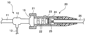
- FIG. 2 is an explanatory diagram illustrating an endoscope and a camera head that supply an endoscope image to the endoscope image generation apparatus in FIG. 1.
- FIG. 1 is a block diagram showing an endoscope image generating apparatus according to a first embodiment of the present invention.
- FIG. 2 is an explanatory diagram showing an endoscope and a camera head that supply a captured image (endoscopic image) to the endoscope image generation apparatus of FIG.
- the endoscope 10 includes an elongated insertion portion 11 that is inserted into a body cavity or a duct.
- An operation unit 12 for holding and operating the endoscope 10 is connected to the proximal end side of the insertion unit 11, and illumination light from a light source device (not shown) is connected to the endoscope from, for example, a side portion of the operation unit 12.
- a light guide cable 13 that guides light to 10 is extended.
- an eyepiece unit 15 that enables visual observation of a subject optical image obtained by the endoscope 10 is provided.
- the camera head 20 can be detachably attached to the eyepiece 15 using the mount 21.
- the camera head 20 includes an image sensor 23 that captures a subject optical image emitted from the eyepiece unit 15.
- the subject optical image emitted from the eyepiece unit 15 is formed on the imaging surface of the image sensor 23 via the lens group 22 having a zoom function.
- the image sensor 23 photoelectrically converts a subject optical image formed on the imaging surface and outputs an imaging signal including the subject image.
- An image pickup signal from the image pickup device 23 is transmitted to the camera control circuit 24, and is supplied from the camera control circuit 24 to the endoscope image generation device 30 in FIG. 1 through a signal line 25 inserted into the signal cable 26. It has become so. Further, the camera control circuit 24 generates a drive signal based on various signals from the endoscope image generation apparatus 30 to drive the image sensor 23.
- the camera control circuit 24 can output zoom information indicating the zoom magnification of the optical zoom based on the lens group 22 to the endoscope image generation apparatus 30 via the signal line 25. This zoom magnification can be set to an arbitrary value by a user operation.
- the endoscope image generating apparatus 30 includes a power supply circuit 31, and the power supply circuit 31 is supplied with an AC commercial power supply via a plug 32, so that an automatic light control circuit 33 and an image are displayed.
- a power supply voltage for the signal processing circuit 41 is generated.
- the automatic dimming circuit 33 receives an operation signal based on a user operation on the operation panel 34, generates a dimming signal for controlling the brightness of a light source supplied to the endoscope 10 from a light source device (not shown), and outputs the dimming signal. Output to the terminal 35.
- the imaging signal from the camera head 20 is input to the input terminal 51.
- This imaging signal is given to the CDS circuit 42 of the video signal processing circuit 41.
- the CDS circuit 42 performs CDS (correlated double sampling) processing on the input imaging signal to extract a video signal component.
- the analog video signal obtained by the CDS circuit 42 is given to an A / D conversion circuit 43.
- the A / D conversion circuit 43 converts the analog video signal into a digital video signal and a digital signal processor (DSP) 44 for video signal processing. Output to.
- DSP digital signal processor
- the video signal processing DSP 44 performs various video signal processing on the digital video signal from the A / D conversion circuit 43 and outputs an output captured image to the image memory 45.
- the video signal processing DSP 44 performs, for example, white balance processing, contour enhancement processing, gamma correction, luminance / color signal separation processing, and electronic zoom processing as various video signal processing.
- the image memory 45 is controlled by the memory control unit 47 to write and read digital video signals.
- the memory control unit 47 controls writing and reading of the image memory 45 based on the output of the captured image position correction unit 46 to correct and output the display position of the output captured image input to the image memory 45.
- the memory control unit 47 can correct the display position of the subject image included in the output captured image from the image memory 45 to an arbitrary position.
- zoom information indicating the zoom magnification of the optical zoom based on the lens group 22 of the camera head 20 is input to the terminal 52.
- This zoom information is supplied to the captured image position correction unit 46.
- zoom information indicating the zoom magnification in the electronic zoom processing is also captured.
- the position correction unit 46 is provided.
- the video signal processing DSP 44 can set an arbitrary zoom magnification based on a user operation.
- the captured image position correction unit 46 receives the video signal from the video signal processing DSP 44, and performs an analysis using the image analysis and zoom information on the input video signal and the center of the subject image captured by the image sensor and the output captured image.
- the memory control unit 47 is controlled by generating correction information for correcting the deviation from the center of the memory.
- the captured image position correction unit 46 calculates the shift between the center of the subject image captured by the image sensor and the center of the output captured image by image analysis on the video signal to obtain the initial shift correction amount.
- a deviation correction amount obtained by correcting the initial deviation correction amount based on the ratio between the zoom magnification at the time of deviation calculation and the current zoom magnification is obtained and output to the memory control unit 47 as correction information. If the current zoom magnification has not changed from the zoom magnification at the time of deviation calculation, the initial deviation correction amount is directly given to the memory control unit 47 as the deviation correction amount.
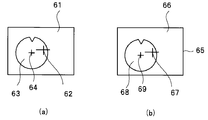
- FIG. 3 is an explanatory diagram for explaining an example of a method of calculating a deviation amount by the captured image position correction unit 46.
- FIG. 3A shows the positional relationship between the imaging region 61 of the imaging device 23 and the subject optical image 63 obtained from the eyepiece 15.
- FIG. 3A shows an example in which the size of the subject optical image 63 is smaller than that of the imaging region 61. However, depending on the endoscope, the size of the subject optical image may be larger than that of the imaging region 61. possible.
- the center of the field of view of the endoscope obtained in the eyepiece unit 15 with respect to the center 62 of the imaging region 61, that is, the center of the subject optical image 63. 64 is shifted.
- FIG. 3B shows this state.
- An output captured image 66 displayed on the entire display screen 65 of the monitor is an image corresponding to the imaging region 61 of the image sensor 23.
- the output captured image 66 includes a subject image 68 based on the subject optical image 63. Due to the deviation between the optical center of the image sensor 23 and the optical center of the subject optical image 63, a deviation occurs between the center 67 of the output captured image 66 (center of the display screen 65) and the center 69 of the subject image 68.
- the captured image position correction unit 46 calculates this deviation as described above.
- a portion other than the subject image 68 in the output captured image 66 is, for example, a black level image, and the luminance is sufficiently low.
- the captured image position correction unit 46 uses this to determine the position of the subject image 68.
- the captured image position correction unit 46 receives the video signal from the video signal processing DSP 44, and detects a change in brightness in the horizontal direction for a plurality of horizontal lines in the output captured image 66 from the luminance signal component. To do. A portion other than the subject image 68 in the output captured image 66 has, for example, a black level, and the brightness changes relatively greatly at the boundary between the subject image 68 and other portions on a predetermined horizontal line. Thereby, the captured image position correcting unit 46 can obtain the position of the boundary of the subject image 68 on a predetermined horizontal line.
- the captured image position correction unit 46 obtains the position of the boundary between the subject image 68 and other portions from the change in luminance on a plurality of horizontal lines. Since the subject image 68 is substantially circular, the captured image position correction unit 46 detects the position of the center 69 of the subject image 68 in the output captured image 66 by calculating the center of curvature of the boundary position thus obtained. The captured image position correction unit 46 calculates a deviation amount between the center position of the output captured image 66 and the obtained center position of the subject image 68.
- the captured image position correction unit 46 can obtain the deviation amount (initial deviation amount) by (BA), where A is the center position of the output captured image 66, B is the center position of the subject image 68, and the initial deviation. Let the correction amount be (BA).
- the captured image position correction unit 46 holds the initial deviation amount (initial deviation correction amount) in a memory (not shown) and also holds information on the zoom magnification when calculating the initial deviation amount in a memory (not shown).
- the captured image position correction unit 46 obtains a deviation correction amount obtained by correcting the initial deviation correction amount according to the zoom magnification. That is, the captured image position correction unit 46 determines the shift correction amount when the zoom magnification is changed to ⁇ by the following equation (1), assuming that the zoom magnification at the time of calculating the initial shift amount is ⁇ . If there is no change in the zoom magnification, the captured image position correction unit 46 outputs the initial shift correction amount to the memory control unit 47 as a shift correction amount for shift correction.
- the center position of the subject image 68 is output using the initial deviation correction amount obtained only once.
- the initial deviation correction amount may be obtained immediately after the power is turned on or before the zoom operation.
- the calculation amount of a large amount of calculation is performed only once, and the shift correction amount can be obtained with a small amount of calculation by using information on the zoom magnification. Even if the zoom operation is performed, it is possible to reliably perform the deviation correction.
- the shift amount is obtained by utilizing the fact that the luminance difference between the subject image 68 and other portions is large.
- the luminance of the subject image 68 is relatively low, the detection accuracy of the boundary position of the subject image 68 is deteriorated, and there is a case where it is impossible to reliably detect the deviation amount.
- the amount of deviation may be obtained only once after the power is turned on.
- the amount of deviation may be obtained during white balance adjustment before inserting the insertion unit 11 into the subject.
- the white balance adjustment is performed, for example, with a white cap attached to the distal end of the insertion portion, and the subject image 68 becomes white. For this reason, the luminance difference between the subject image 68 and other portions is large, and the boundary position of the subject image 68 can be reliably detected.
- the memory control unit 47 is provided with information on the shift correction amount from the captured image position correction unit 46, and controls reading of the image memory 45 so that the subject image 68 is shifted by the shift correction amount. That is, when the digital video signal is read from the image memory 45, the reading is performed so that the center of the subject image 68 is positioned at the center of the output captured image 66, that is, the center of the display screen 65 of the monitor.
- the video signal (output captured image) read from the image memory 45 is supplied to a D / A conversion circuit 48, which converts the input digital video signal into an analog video signal, for example, RGB An RGB video signal, which is a format video signal, is obtained and output from the output terminal 53.
- the encoder 49 is supplied with the output video signal of the D / A conversion circuit 48, and is a Y / C separated video signal that is a Y / C (luminance / color) separated video signal or a composite video signal.
- a composite video signal is obtained and output from output terminals 54 and 55, respectively.
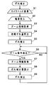
- FIG. 4 is a flowchart for explaining the operation of the first embodiment
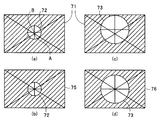
- FIG. 5 is an explanatory diagram for explaining the shift of the center of the subject image included in the captured image and the correction thereof.
- the mount portion 21 of the camera head 20 is attached to the eyepiece portion 15 of the endoscope 10.
- the power supply circuit 31 starts supplying power to each unit.
- An imaging signal and zoom information are output from the camera head 20 via the signal line 25.
- the imaging signal and zoom information are input to the endoscope image generating apparatus 30 via terminals 51 and 52, respectively.
- the captured image position correction unit 46 acquires zoom information input via the terminal 52 (step S3).
- the captured image position correction unit 46 also acquires zoom information indicating a zoom magnification in the electronic zoom process when the electronic zoom process is performed by the video signal processing DSP 44.
- the captured image position correction unit 46 calculates an initial deviation amount.
- the initial deviation amount may be calculated during white balance adjustment.
- the subject image is white and the portion other than the subject image is at the black level, so that the boundary position of the subject image can be easily detected.
- the calculation of the initial deviation amount is obtained by processing the captured image from the image sensor 23.
- the subject optical image captured from the distal end of the insertion unit 11 is emitted from the eyepiece unit 15 and formed on the imaging surface of the image sensor 23.
- the image sensor 23 photoelectrically converts the subject optical image and outputs a captured image (imaging signal).
- This imaging signal is taken into the CDS circuit 42 via the terminal 51 of the endoscope image generating device 30.
- the CDS circuit 42 extracts a video signal component from the input image pickup signal, and the extracted video signal is converted into a digital signal by the A / D conversion circuit 43 and given to the video signal processing DSP 44. After performing various video signal processing, the video signal processing DSP 44 outputs the output captured image to the image memory 45 and the captured image position correction unit 46.
- the video signal (output captured image) read from the image memory 45 is returned to an analog signal by the D / A conversion circuit 48 and then output from the terminal 53 as an RGB video signal. Also, the output of the D / A conversion circuit 48 is converted into a Y / C separated video signal by the encoder 49 and output from the terminal 54, and also converted into a composite video signal and output from the terminal 55. By supplying these video signals to a monitor (not shown), a subject image obtained by the endoscope 10 is displayed on the display screen of the monitor.
- FIG. 5A shows the positional relationship between the output captured image 71 output from the video signal processing DSP 44 and the subject image 72 included in the output captured image 71 when the zoom magnification is ⁇ times.
- the example of FIG. 5A shows an example in which the center position of the output captured image 71 is A and the center position of the subject image 72 is B.
- FIG. 5 shows an example in which the center position of the subject image 72 is shifted only in the vertical direction with respect to the center position of the output captured image 71 in order to simplify the description. Similarly, correction is possible.
- the hatched portion in FIG. 5 indicates a black level region other than the subject image portion.
- the captured image position correction unit 46 stores the shift amount (initial shift amount) calculated in step S4 in a memory (not shown).
- the initial deviation amount is (BA).
- the deviation amount remains the initial deviation amount.
- the captured image position correction unit 46 outputs the initial shift correction amount (BA) with respect to the initial shift amount to the memory control unit 47 as a shift correction amount.
- the memory control unit 47 shifts the reading from the image memory 45 by the shift correction amount, so that the center position of the subject image 72 is displayed on the display screen of the monitor as shown in FIG. Is read out so as to be positioned at the center (the center of the display screen of the monitor) (step S5).
- the center position of the subject image 72 is displayed on the display screen of the monitor as shown in FIG. Is read out so as to be positioned at the center (the center of the display screen of the monitor) (step S5).
- an easy-to-see image with the subject image 72 displayed at the center is displayed on the display screen of the monitor as shown in FIG.
- step S6 when a change in zoom magnification is detected (step S6), zoom information is acquired in step S7, and a deviation correction amount is calculated in step S8. That is, the captured image position correction unit 46 obtains the shift correction amount by the calculation of the above equation (1) using the ratio between the initial shift amount and the zoom magnification.
- the information of the deviation correction amount is given to the memory control unit 47, and the memory control unit 47 shifts the reading from the image memory 45 by the deviation correction amount.
- the readout control is performed so that the center position of the subject image 73 is positioned at the center of the output captured image 76 displayed on the monitor display screen (the center of the monitor display screen). Is called.
- FIG. 4 shows an example in which the process proceeds to step S7 after it is determined that the zoom magnification has changed. However, a predetermined time period after the shift correction in step S5 is performed without determining the change in zoom magnification. Steps S7 to S9 may be performed at intervals.
- the deviation between the center of the output captured image and the center of the subject image is obtained as the initial deviation amount, and the ratio between the zoom magnification at the time of calculating the initial deviation amount and the current zoom magnification is obtained.
- the amount of deviation correction is obtained by correcting the amount of initial deviation.
- FIG. 6 is a block diagram showing a second embodiment of the present invention.
- the endoscope image generation apparatus 80 in this embodiment employs a video signal processing circuit 81 to which an auto zoom processing unit 82, a mask detection unit 83, and a zoom magnification setting unit 84 are added instead of the video signal processing circuit 41.
- This is different from the endoscope image generation apparatus 30 according to the first embodiment.
- the present embodiment shows an example in which the present invention is applied to an object having an auto zoom processing function that automatically displays a subject image in a full display screen of a monitor.
- FIG. 7 is an explanatory diagram for explaining a display during auto-zoom processing.
- the subject image portion is cut out from the captured image, and the size is changed according to the size of the monitor, and then output to the monitor.
- FIG. 7A shows a captured image 91 obtained by the image sensor 23, and the captured image 91 includes a subject image 92.
- a portion other than the subject image 92 in the captured image 91 is, for example, a black level mask region 93.
- FIG. 7B shows an output captured image 95 displayed on the display screen 94 of the monitor.
- an enlarged image 96 based on the subject image 92 is displayed in the full display range of the display screen 94.
- the monitor generally has various display modes (scan modes), and the scan range of the monitor does not necessarily match the entire display range of the display screen.
- the display range may be narrower than the scan range.
- FIG. 7C shows such a scan mode of the monitor.
- the solid line square indicates the scan range 97
- the broken line square indicates the display range 98 in the display screen 94.
- the cutting and size changing process is performed on the premise that the output captured image is displayed over the entire scan range of the monitor. Therefore, when the output captured image 95 of FIG. 7B is input to the monitor, as shown in FIG. 7C, the enlarged image 96 based on the subject image 92 protrudes from the display range 98, and FIG. As shown in d), on the display screen 94, an enlarged image 96 ′ lacking a part is displayed.
- a zoom magnification setting unit 84 is provided.
- the video signal from the image memory 45 is supplied to the auto zoom processing unit 82 and the mask detection unit 83.
- the mask detection unit 83 detects a portion other than the subject image in the captured image as a mask region based on a change in luminance of the input video signal, and outputs the detection result to the zoom magnification setting unit 84.
- the auto zoom processing unit 82 sets the zoom magnification by the zoom magnification setting unit 84, and cuts out and outputs the input image within the cutout range corresponding to the set zoom magnification.
- scan mode information is input to the zoom magnification setting unit 84 from a monitor (not shown).
- the scan mode information is information indicating the monitor scan mode, and includes information indicating the current scan range of the monitor.
- the zoom magnification setting unit 84 Based on the output of the mask detection unit 83 and the scan mode information from the monitor, the zoom magnification setting unit 84 has the maximum size of the enlarged image based on the subject image during auto zoom processing, and all of the enlarged images are within the display range. As shown, a zoom magnification (maximum zoom magnification) for determining a cut-out range for auto zoom processing is obtained and output to the auto zoom processing unit 82.
- the zoom magnification setting unit 84 receives a mask detection result from the mask detection unit 83 and scan mode information from a monitor (not shown).
- the zoom magnification setting unit 84 determines a zoom magnification for determining the extraction range by the auto zoom processing unit 82 based on the mask detection result and the scan mode information.
- the information of the zoom magnification from the zoom magnification setting unit 84 is supplied to the auto zoom processing unit 82.
- the auto zoom processing unit 82 cuts out the subject image portion from the input image within the cutout range corresponding to the set zoom magnification, and Change the size according to the display screen and output.
- the output captured image 99 displayed on the display screen 94 lacks the enlarged image 96 ′′ based on the subject image 92 in the full display range 98 of the display screen 94. It is displayed without.
- the subject image can always be displayed on the full display screen regardless of the scan mode of the monitor. it can.
- FIG. 8 is a block diagram showing a modification.
- FIG. 8 shows only a part of the configuration, and is different from the apparatus of FIG. 6 only in that a message generator 101 and an image superimposing unit 102 are added.
- the endoscope image generating apparatus according to the second embodiment has an auto zoom processing function for automatically zooming the subject image to fill the display screen.
- the size of the subject optical image obtained from the eyepiece 15 may be larger than the imaging area of the imaging device 23. If the mechanical accuracy is low, the center of the subject optical image may be greatly deviated from the center of the imaging region, and a part of the subject optical image may protrude from the imaging region of the image sensor 23. In these cases, the image sensor 23 cannot obtain an image based on a part of the subject optical image, and the auto zoom process is not performed. However, the user is not sure why the auto zoom process is not performed.
- the message generation unit 101 determines whether or not auto-zoom processing is impossible based on the detection result of the mask detection unit 83. A message to be shown is generated and presented to the user.
- the message generation unit 101 can auto-zoom only when the luminance of all pixels in the uppermost one line, the lowermost line, the leftmost column, and the rightmost column of the imaging area is equal to or lower than a predetermined black level. You may judge that. That is, when the luminance of one or more pixels in all the pixels in the two lines at the upper and lower ends and the two columns at the left and right ends of the imaging region exceeds a predetermined black level, the message generator 101 Are pixels included in the subject image, and it is determined that only a captured image lacking a part of the subject optical image can be obtained from the image sensor 23, and a determination result indicating that auto-zoom is impossible is obtained.
- the message generator 101 determines that auto-zoom is not possible, for example, it outputs message information for displaying a display indicating that auto-zoom is invalid on a monitor (not shown). This message information is given to the image superimposing unit 102.
- the image superimposing unit 102 superimposes the message display data on the output image of the auto zoom processing unit 82 and outputs it.
- FIG. 9 is an explanatory diagram for explaining the message display.
- FIG. 9A shows an output captured image 112 displayed on the display screen 110 of the monitor when auto zoom processing is possible. In the output captured image 112, the subject optical image 111 is displayed in the full display range.
- FIG. 9B shows a display when it is determined that auto-zoom is impossible, and a message display 113 “Auto-zoom is invalid” is displayed on the display screen 110.
- the message display 113 allows the user to recognize that auto-zoom is not possible with the endoscope attached to the camera head 20.
- the present invention is not limited to the above-described embodiments as they are, and can be embodied by modifying constituent elements without departing from the scope of the invention in the implementation stage.
- various inventions can be formed by appropriately combining a plurality of constituent elements disclosed in the above embodiments. For example, you may delete some components of all the components shown by embodiment.
- constituent elements over different embodiments may be appropriately combined.
- the controls and functions mainly described in the flowcharts can be set by a program, and the above-described controls and functions can be realized by a computer reading and executing the program. it can.
- the program may be recorded or stored in whole or in part on a portable medium such as a non-volatile memory such as a flexible disk or a CD-ROM, or a storage medium such as a hard disk or a volatile memory. It can be distributed or provided at the time of product shipment or via a portable medium or communication line.
- the user can easily realize the exemplary embodiment by downloading the program via a communication network and installing the program on a computer, or installing the program on a computer from a recording medium.
Landscapes
- Physics & Mathematics (AREA)
- Health & Medical Sciences (AREA)
- Life Sciences & Earth Sciences (AREA)
- Engineering & Computer Science (AREA)
- Surgery (AREA)
- Optics & Photonics (AREA)
- Animal Behavior & Ethology (AREA)
- Heart & Thoracic Surgery (AREA)
- Veterinary Medicine (AREA)
- Biophysics (AREA)
- Nuclear Medicine, Radiotherapy & Molecular Imaging (AREA)
- Pathology (AREA)
- Radiology & Medical Imaging (AREA)
- Public Health (AREA)
- Biomedical Technology (AREA)
- General Health & Medical Sciences (AREA)
- Medical Informatics (AREA)
- Molecular Biology (AREA)
- Astronomy & Astrophysics (AREA)
- General Physics & Mathematics (AREA)
- Multimedia (AREA)
- Signal Processing (AREA)
- Endoscopes (AREA)
- Instruments For Viewing The Inside Of Hollow Bodies (AREA)
Abstract
内視鏡用画像生成装置は、カメラヘッドからの撮像信号が入力され、入力された撮像信号に基づいて表示部に表示可能な出力撮像画像を生成する画像処理部と、前記出力撮像画像に対する前記被写体画像のサイズを示すズーム倍率の情報を取得するズーム情報取得部と、前記出力撮像画像の中心と前記被写体画像の中心とのずれ量を算出するずれ量算出部と、前記ずれ量算出時における第1のズーム倍率と設定される第2のズーム倍率との比と、前記ずれ量算出部が算出した前記ずれ量とに基づいて、前記出力撮像画像の中心と前記被写体画像の中心とのずれを補正するずれ補正量を算出するずれ補正量算出部と、前記ずれ補正量に基づいて前記被写体画像の中心が前記出力撮像画像の中心に一致するように前記出力撮像画像を補正して前記表示部に出力する位置補正部とを具備する。
Description
本発明は、ズーム機能を有する内視鏡に好適な内視鏡用画像生成装置及び内視鏡用画像生成方法に関する。
従来より、体腔内等へ細長の内視鏡を挿入して被検部位の観察や各種処置を行うようにした内視鏡が広く用いられている。また、工業分野においても、ボイラ、タービン、エンジン、化学プラントなどの内部の傷や腐蝕などを観察したり検査することのできる工業用内視鏡が広く利用されている。
内視鏡は細長の挿入部を有しており、挿入部の先端部から取り込んだ被写体像を挿入部の基端側において観察可能である。挿入部先端部にCCD等の撮像素子を設けたり、基端側の接眼部にカメラヘッドを取り付けたりすることで、被写体像を映像信号に変換して、内視鏡の手元側に接続されたプロセッサに伝送することもできる。プロセッサは、伝送された映像信号に基づいて内視鏡画像を生成し、この内視鏡画像をモニタに供給して表示を行う。
カメラヘッドを装着可能な内視鏡は、挿入部先端部の対物レンズから取り込んだ被写体の光学像を例えばリレーレンズにより挿入部後側の接眼部に伝送する。カメラヘッドは、先端側にマウント部を有しており、マウント部を利用してカメラヘッドを挿入部の後端の接眼部に装着することができるようになっている。カメラヘッドの先端側には、結像レンズが配置されており、結像レンズの結像位置にはCCD等の撮像素子が配置される。こうして、挿入部先端から取り込んだ被写体光学像をカメラヘッドの撮像素子の撮像面上において結像させ、撮像素子により被写体画像の画像信号を取得することができる。
ところで、カメラヘッドのマウント部と挿入部の接眼部との機械的な精度によっては、撮像素子の光学中心と、接眼部の光学中心とにずれが生じることがある。このずれが比較的大きい場合には、モニタの表示画面の中央に被写体像が表示されず、被写体画像が見難くなってしまう。
そこで、日本国特開2000-227560号公報(以下、文献1という)においては、撮像素子によって撮像した被写体画像の中心と撮像画像の中心とのずれ量を算出し、撮像画像の表示位置をずれ量分だけ補正することで、被写体画像をモニタの表示画面の中央に表示させるようにした装置が開示されている。
従来、カメラヘッドにおいては、ズーム機能を有するものがある。撮像した被写体画像の中心と撮像画像の中心とのずれ量は、ズーム倍率の変化に応じて変化する。このため、文献1の提案においては、少なくともズーム倍率が変化する毎にずれ量の算出を行う必要がある。被写体画像の中心と撮像画像の中心とのずれ量の算出に必要な演算量は極めて大きく、ズーム操作時における演算量の増大から、文献1の装置では、比較的高い能力の演算回路を必要とするという問題があった。また、文献1の装置においては、画像処理によって、撮像画像中における被写体画像の中心の位置を求めるようになっており、被写体画像の絵柄によっては中心の算出が困難で、中心の検出精度が低下することがあり、表示位置のずれの補正が確実に行われないことがあるという問題もあった。
本発明は、被写体画像の中心と撮像画像の中心とのずれ量の補正量を簡単に算出可能にして、表示位置のずれの補正を確実に行うことができる内視鏡用画像生成装置及び内視鏡用画像生成方法を提供することを目的とする。
本発明に係る内視鏡用画像生成装置は、撮像部の撮像面に、内視鏡の接眼部から入射された被写体光学像が結像し、前記被写体光学像に基づく被写体画像を含む撮像信号を得るカメラヘッドからの前記撮像信号が入力され、入力された撮像信号に基づいて表示部に表示可能な出力撮像画像を生成する画像処理部と、前記出力撮像画像に対する前記被写体画像のサイズを示すズーム倍率の情報を取得するズーム情報取得部と、前記出力撮像画像の中心と前記被写体画像の中心とのずれ量を算出するずれ量算出部と、前記ずれ量算出時における第1のズーム倍率と設定される第2のズーム倍率との比と、前記ずれ量算出部が算出した前記ずれ量とに基づいて、前記出力撮像画像の中心と前記被写体画像の中心とのずれを補正するずれ補正量を算出するずれ補正量算出部と、前記ずれ補正量に基づいて前記被写体画像の中心が前記出力撮像画像の中心に一致するように前記出力撮像画像を補正して前記表示部に出力する位置補正部とを具備する。
また、本発明に係る内視鏡用画像生成方法は、撮像部の撮像面に、内視鏡の接眼部から入射された被写体光学像が結像し、前記被写体光学像に基づく被写体画像を含む撮像信号を得るカメラヘッドからの前記撮像信号が入力され、入力された撮像信号に基づいて表示部に表示可能な出力撮像画像を生成する画像処理ステップと、前記出力撮像画像に対する前記被写体画像のサイズを示すズーム倍率の情報を取得するズーム情報取得ステップと、画像処理によって、前記画像処理ステップによって得られた前記出力撮像画像の中心と前記被写体画像の中心とのずれ量を算出するずれ量算出ステップと、前記ずれ量算出時における第1のズーム倍率と変化した第2のズーム倍率との比と、前記ずれ量算出ステップにおいて算出された前記ずれ量とに基づいて、前記出力撮像画像の中心と前記被写体画像の中心とのずれを補正するずれ補正量を算出し、算出した前記ずれ補正量に基づいて前記被写体画像の中心が前記出力撮像画像の中心に一致するように前記画像処理ステップにおいて得られた前記出力撮像画像を補正して前記表示部に出力する位置補正ステップとを具備する。
以下、図面を参照して本発明の実施の形態について詳細に説明する。
(第1の実施の形態)
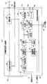
図1は本発明の第1の実施の形態に係る内視鏡用画像生成装置を示すブロック図である。また、図2は図1の内視鏡用画像生成装置に撮像画像(内視鏡画像)を供給する内視鏡及びカメラヘッドを示す説明図である。
図1は本発明の第1の実施の形態に係る内視鏡用画像生成装置を示すブロック図である。また、図2は図1の内視鏡用画像生成装置に撮像画像(内視鏡画像)を供給する内視鏡及びカメラヘッドを示す説明図である。
図2において、内視鏡10は、体腔内或いは管路内等に挿入する細長の挿入部11を備えている。挿入部11の基端側には、内視鏡10を把持し操作するための操作部12が連接され、この操作部12の例えば側部からは図示しない光源装置からの照明光を内視鏡10へ導光するライトガイドケーブル13が延出されている。操作部12の例えば基端側には、内視鏡10で得られる被写体光学像を眼視観察可能にする接眼部15が設けられている。
この接眼部15には、マウント部21を利用してカメラヘッド20を着脱自在に取り付け可能である。カメラヘッド20は、接眼部15から射出される被写体光学像を撮像する撮像素子23を有している。接眼部15から射出された被写体光学像は、ズーム機能を有するレンズ群22を介して撮像素子23の撮像面に結像するようになっている。撮像素子23は、撮像面に結像した被写体光学像を光電変換して、被写体画像を含む撮像信号を出力する。
撮像素子23からの撮像信号は、カメラ制御回路24に伝送され、カメラ制御回路24から信号ケーブル26内に挿通された信号線25を介して図1の内視鏡用画像生成装置30に供給されるようになっている。また、カメラ制御回路24は、内視鏡用画像生成装置30からの各種信号に基づいて駆動信号を生成して撮像素子23を駆動するようになっている。なお、カメラ制御回路24は、レンズ群22に基づく光学ズームのズーム倍率を示すズーム情報を信号線25を介して内視鏡用画像生成装置30に出力することができるようになっている。このズーム倍率は、ユーザ操作によって任意の値に設定可能である。
図1に示すように、内視鏡用画像生成装置30は、電源回路31を有しており、電源回路31はプラグ32を介して交流商用電源が供給されて、自動調光回路33及び映像信号処理回路41の電源電圧を発生する。自動調光回路33は、操作パネル34に対するユーザ操作に基づく操作信号が与えられて、図示しない光源装置から内視鏡10に供給する光源の明るさを制御する調光信号を発生して、出力端子35に出力する。
入力端子51には、カメラヘッド20からの撮像信号が入力される。この撮像信号は映像信号処理回路41のCDS回路42に与えられる。CDS回路42は、入力された撮像信号にCDS(相関二重サンプリング)処理を施して映像信号成分を抽出する。CDS回路42で得られたアナログ映像信号はA/D変換回路43に与えられ、A/D変換回路43はアナログ映像信号をデジタル映像信号に変換して映像信号処理用デジタルシグナルプロセッサ(DSP)44に出力する。
映像信号処理用DSP44は、A/D変換回路43からのデジタル映像信号に対して各種映像信号処理を施して、出力撮像画像を画像メモリ45に出力する。例えば、映像信号処理用DSP44は、各種映像信号処理として、例えば、ホワイトバランス処理、輪郭強調処理、ガンマ補正、輝度/色信号分離処理及び電子ズーム処理等を行う。
本実施の形態においては、画像メモリ45は、メモリ制御部47によってデジタル映像信号の書き込み及び読み出しが制御されるようになっている。メモリ制御部47は、撮像画像位置補正部46の出力に基づいて画像メモリ45の書き込み及び読み出しを制御して、画像メモリ45に入力された出力撮像画像の表示位置を補正して出力する。メモリ制御部47によって、画像メモリ45からの出力撮像画像中に含まれる被写体画像の表示位置を任意の位置に補正することが可能である。
本実施の形態においては、端子52にはカメラヘッド20のレンズ群22に基づく光学ズームのズーム倍率を示すズーム情報が入力される。このズーム情報は撮像画像位置補正部46に供給される。また、映像信号処理回路41は、映像信号処理用DSP44において撮像画像の一部を切出して出力する所謂電子ズーム処理を行った場合には、この電子ズーム処理におけるズーム倍率を示すズーム情報も撮像画像位置補正部46に与えるようになっている。なお、映像信号処理用DSP44は、ユーザ操作に基づいて、任意のズーム倍率を設定可能である。
撮像画像位置補正部46は、映像信号処理用DSP44から映像信号が与えられ、入力された映像信号に対する画像解析及びズーム情報を用いた演算によって、撮像素子によって撮像した被写体画像の中心と出力撮像画像の中心とのずれを補正するための補正情報を生成してメモリ制御部47を制御するようになっている。
本実施の形態においては、撮像画像位置補正部46は、映像信号に対する画像解析によって、撮像素子によって撮像した被写体画像の中心と出力撮像画像の中心とのずれを算出して初期ずれ補正量を求めると共に、ずれ算出時のズーム倍率と、現在のズーム倍率との比に基づいて初期ずれ補正量を補正したずれ補正量を求めて、補正情報としてメモリ制御部47に出力する。なお、現在のズーム倍率がずれ算出時のズーム倍率から変化していない場合には、初期ずれ補正量がそのままずれ補正量としてメモリ制御部47に与えられる。
図3は撮像画像位置補正部46によるずれ量の算出方法の一例を説明するための説明図である。図3(a)は撮像素子23の撮像領域61と接眼部15から得られる被写体光学像63との位置関係を示している。図3(a)は、撮像領域61に対して被写体光学像63のサイズが小さい例を示しているが、内視鏡によっては被写体光学像のサイズの方が撮像領域61よりも大きくなることもあり得る。図3(a)では、機械的な精度の低さによって、撮像領域61の中心62に対して、接眼部15において得られる内視鏡の視野範囲の中心、即ち、被写体光学像63の中心64がずれている。
撮像領域61の全域において得られる撮像画像の全てをそのままモニタの表示画面の全域に表示させた場合や、撮像領域61の中心がモニタの表示画面の中心に対応するように撮像画像の表示を行う場合には、モニタの表示画面の中心と被写体光学像63に基づく被写体画像の中心とにずれが生じることになる。図3(b)はこの状態を示している。モニタの表示画面65上の全域に表示される出力撮像画像66は、撮像素子23の撮像領域61に対応した画像である。出力撮像画像66中には、被写体光学像63に基づく被写体画像68が含まれる。撮像素子23の光学中心と被写体光学像63の光学中心とのずれによって、出力撮像画像66の中心(表示画面65の中心)67と被写体画像68の中心69とにはずれが生じている。
撮像画像位置補正部46は、上述したように、このずれを算出する。出力撮像画像66中の被写体画像68以外の部分は例えば黒レベルの画像であって、輝度が十分に低い。撮像画像位置補正部46は、このことを利用して、被写体画像68の位置を求める。
例えば、撮像画像位置補正部46は、映像信号処理用DSP44からの映像信号が与えられ、その輝度信号成分から、出力撮像画像66内の複数の水平ラインについて、水平方向の明るさの変化を検出する。出力撮像画像66中の被写体画像68以外の部分は例えば黒レベルであり、所定の水平ライン上では、被写体画像68とその他の部分との境界において、明るさが比較的大きく変化する。これにより、撮像画像位置補正部46は、所定の水平ライン上における被写体画像68の境界の位置を得ることができる。
同様に、撮像画像位置補正部46は、複数の水平ライン上において、輝度の変化から被写体画像68とその他の部分との境界の位置を求める。被写体画像68は略円形であるので、撮像画像位置補正部46は、こうして求めた境界位置の曲率中心を算出することで、出力撮像画像66中における被写体画像68の中心69の位置を検出する。撮像画像位置補正部46は、出力撮像画像66の中心位置と、求めた被写体画像68の中心位置とのずれ量を算出する。
撮像画像位置補正部46は、出力撮像画像66の中心位置をAとし、被写体画像68の中心位置をBとして、ずれ量(初期ずれ量)を(B-A)によって求めることができ、初期ずれ補正量を(B-A)とする。撮像画像位置補正部46は、初期ずれ量(初期ずれ補正量)を図示しないメモリに保持させると共に、初期ずれ量の算出時におけるズーム倍率の情報を図示しないメモリに保持する。
更に、撮像画像位置補正部46は、初期ずれ補正量の算出後にズーム倍率が変化すると、初期ずれ補正量をズーム倍率に応じて補正したずれ補正量を求める。即ち、撮像画像位置補正部46は、初期ずれ量の算出時におけるズーム倍率がαであるものとすると、ズーム倍率がβに変化した場合におけるずれ補正量を、下記(1)式によって求める。なお、ズーム倍率に変化がない場合には、撮像画像位置補正部46は、初期ずれ補正量をずれ補正のためのずれ補正量としてメモリ制御部47に出力する。
(β/α)×(B-A) …(1)
上記(1)式は、ズーム倍率を用いることで、ズーム倍率を変化させる操作が行われた場合でも、1回だけ求めた初期ずれ補正量を用いて、被写体画像68の中心位置を出力撮像画像66の中心位置に補正するためのずれ補正量を求めることができることを示している。例えば、電源投入直後、ズーム操作前等に、初期ずれ補正量を求めるようにしてもよい。本実施の形態においては、演算量が大きいずれ量の算出処理を1回だけ行い、ズーム倍率の情報を用いることで少ない演算量でずれ補正量を求めることができ、比較的小さい回路規模の装置であっても、またズーム操作時であっても確実なずれ補正が可能である。
上記(1)式は、ズーム倍率を用いることで、ズーム倍率を変化させる操作が行われた場合でも、1回だけ求めた初期ずれ補正量を用いて、被写体画像68の中心位置を出力撮像画像66の中心位置に補正するためのずれ補正量を求めることができることを示している。例えば、電源投入直後、ズーム操作前等に、初期ずれ補正量を求めるようにしてもよい。本実施の形態においては、演算量が大きいずれ量の算出処理を1回だけ行い、ズーム倍率の情報を用いることで少ない演算量でずれ補正量を求めることができ、比較的小さい回路規模の装置であっても、またズーム操作時であっても確実なずれ補正が可能である。
また、上述したように、ずれ量は、被写体画像68とその他の部分との輝度差が大きいことを利用して求めている。被写体画像68の輝度が比較的低い場合等においては、被写体画像68の境界位置の検出精度が悪化し、確実なずれ量検出ができない場合がある。
これに対し、本実施の形態においては、接眼部15にカメラヘッド20を装着した後、電源投入後に1回だけずれ量を求めればよい。例えば、挿入部11を被検体に挿入する前のホワイトバランス調整時等に、ずれ量を求めるようにしてもよい。ホワイトバランス調整は、例えば、挿入部の先端にホワイトキャップを装着した状態で行われ、被写体画像68は白色となる。このため、被写体画像68とその他の部分との輝度差が大きく、被写体画像68の境界位置の確実な検出が可能である。
メモリ制御部47は、撮像画像位置補正部46からずれ補正量の情報が与えられて、ずれ補正量だけ被写体画像68がシフトするように画像メモリ45の読み出しを制御する。即ち、画像メモリ45からのデジタル映像信号の読出しに際して、被写体画像68の中心が出力撮像画像66の中心、即ち、モニタの表示画面65の中心に位置するように読み出しが行われることになる。
画像メモリ45から読出された映像信号(出力撮像画像)はD/A変換回路48に与えられ、D/A変換回路48は、入力されたデジタル映像信号をアナログ映像信号に変換して、例えばRGB形式の映像信号であるRGB映像信号を得て、出力端子53から出力する。また、エンコーダ49は、D/A変換回路48の出力映像信号が与えられて、Y/C(輝度/色)分離形式の映像信号であるY/C分離映像信号や、コンポジット形式の映像信号であるコンポジット映像信号を得て、夫々出力端子54,55から出力する。
次に、このように構成された実施の形態の動作について図4及び図5を参照して説明する。図4は第1の実施の形態の動作を説明するためのフローチャートであり、図5は撮像画像に含まれる被写体画像の中心のずれ及びその補正を説明するための説明図である。
図4のステップS1において、内視鏡10の接眼部15に、カメラヘッド20のマウント部21を取り付ける。内視鏡用画像生成装置30の電源が投入されると(ステップS2)、電源回路31は各部への電力供給を開始する。カメラヘッド20からは信号線25を介して撮像信号及びズーム情報が出力される。撮像信号及びズーム情報は夫々端子51,52を介して内視鏡用画像生成装置30に入力される。撮像画像位置補正部46は、端子52を介して入力されたズーム情報を取得する(ステップS3)。なお、撮像画像位置補正部46は、映像信号処理用DSP44によって電子ズーム処理が行われている場合には、電子ズーム処理におけるズーム倍率を示すズーム情報も取得する。
次のステップS4において、撮像画像位置補正部46は、初期ずれ量を算出する。例えば、初期ずれ量の算出は、ホワイトバランス調整時に行ってもよい。ホワイトバランス調整時には、被写体画像が白色で被写体画像以外の部分が黒レベルとなり、被写体画像の境界位置の検出が容易となる。
初期ずれ量の算出は、撮像素子23からの撮像画像に対する処理によって求められる。即ち、挿入部11の先端から取り込まれた被写体光学像が接眼部15から出射されて、撮像素子23の撮像面に結像される。撮像素子23は、被写体光学像を光電変換して撮像画像(撮像信号)を出力する。この撮像信号は内視鏡用画像生成装置30の端子51を介してCDS回路42に取り込まれる。CDS回路42は、入力された撮像信号から映像信号成分を抽出し、抽出された映像信号はA/D変換回路43によってデジタル信号に変換されて映像信号処理用DSP44に与えられる。映像信号処理用DSP44は各種映像信号処理を施した後、出力撮像画像を画像メモリ45及び撮像画像位置補正部46に出力する。
画像メモリ45から読出された映像信号(出力撮像画像)は、D/A変換回路48によってアナログ信号に戻された後、RGB映像信号として端子53から出力される。また、エンコーダ49によって、D/A変換回路48の出力はY/C分離映像信号に変換されて端子54から出力されると共に、コンポジット映像信号に変換されて端子55から出力される。これらの映像信号が図示しないモニタに供給されることで、内視鏡10によって得られた被写体画像がモニタの表示画面上に表示される。
図5(a)はズーム倍率がα倍の場合において、映像信号処理用DSP44から出力される出力撮像画像71と出力撮像画像71中に含まれる被写体画像72との位置関係を示している。図5(a)の例は出力撮像画像71の中心位置がAであり、被写体画像72の中心位置がBである例を示している。図5は説明を簡略化するために、被写体画像72の中心位置が出力撮像画像71の中心位置に対して垂直方向のみにずれた例を示しているが、水平及び垂直方向にずれた場合でも同様に補正可能である。なお、図5中の斜線部分は、被写体画像部分以外の黒レベルの領域を示している。
撮像画像位置補正部46は、ステップS4において算出したずれ量(初期ずれ量)を図示しないメモリに記憶させる。なお、図5(a)の例では、初期ずれ量は(B-A)である。ズーム操作が行われない場合には、ずれ量は初期ずれ量のまま変化しない。撮像画像位置補正部46は、初期ずれ量に対する初期ずれ補正量(B-A)をずれ補正量としてメモリ制御部47に出力する。
メモリ制御部47は、画像メモリ45からの読み出しをずれ補正量だけシフトさせることにより、図5(b)に示すように、被写体画像72の中心位置がモニタの表示画面に表示する出力撮像画像75の中心(モニタの表示画面の中心)に位置するように読出し制御を行う(ステップS5)。これにより、モニタの表示画面上には、図5(b)に示すように、被写体画像72が中央に表示された見やすい画像が表示される。
内視鏡10の挿入部11が被検体に挿入されて撮像が行われた場合でも、ズーム倍率が変化しなければ、初期ずれ量に対するずれ補正量で、画像メモリ45からの読み出しが制御される。ここで、ズーム操作が行われて、ズーム倍率が変化するものとする。仮に、初期ずれ量に対するずれ補正量で画像メモリ45からの読み出しを制御した場合には、図5(c)に示す出力撮像画像71が得られる。出力撮像画像71はズーム倍率がβ(>α)倍になった場合における画像であり、ずれ量も倍率に応じて大きくなったことから、被写体画像73の中心位置は出力撮像画像71の中心位置からずれている。
これに対し、本実施の形態においては、ズーム倍率の変化を検出すると(ステップS6)、ステップS7においてズーム情報を取得し、ステップS8において、ずれ補正量を算出するようになっている。即ち、撮像画像位置補正部46は、初期ずれ量とズーム倍率の比を用いた上記(1)式の演算によって、ずれ補正量を求める。
このずれ補正量の情報がメモリ制御部47に与えられ、メモリ制御部47は、画像メモリ45からの読み出しをずれ補正量だけシフトさせる。これにより、図5(d)に示すように、被写体画像73の中心位置がモニタの表示画面に表示する出力撮像画像76の中心(モニタの表示画面の中心)に位置するように読出し制御が行われる。こうして、ズーム倍率が変化した場合でも、上記(1)式に示す簡単な演算によって、図5(d)に示すように、モニタの表示画面上の中央に被写体画像73が表示された見やすい画像を得ることができる。
なお、図4ではズーム倍率の変化があったことを判定した後ステップS7に移行する例を示したが、ズーム倍率の変化の判定を行うことなく、ステップS5のずれ補正の後、所定の時間間隔でステップS7~S9を実施するようにしてもよい。
このように本実施の形態においては、出力撮像画像の中心と被写体画像の中心とのずれを初期ずれ量として求めると共に、初期ずれ量の算出時のズーム倍率と、現在のズーム倍率との比に基づいて、初期ずれ量を補正することで、ずれ補正量を求める。これにより、比較的複雑な演算が必要な初期ずれ量の算出を1回のみ行うことで、ズーム倍率に拘わらず確実な位置補正が可能であり、簡単な回路で常に被写体画像をモニタの表示画面中央に表示させることが可能である。また、初期ずれ量の算出は、内視鏡にカメラヘッドを装着した後で1回のみ行えばよく、実際の内視鏡観察時に行う必要はないので、例えば、ホワイトバランス調整時に行うことができ、この場合には、被写体画像を適宜設定することができるので、被写体画像の境界部分の検出が容易となり、確実な位置補正が可能となる。
(第2の実施の形態)
図6は本発明の第2の実施の形態を示すブロック図である。図6において図1と同一の構成要素には同一符号を付して説明を省略する。本実施の形態における内視鏡用画像生成装置80は、映像信号処理回路41に代えて、オートズーム処理部82、マスク検知部83及びズーム倍率設定部84を付加した映像信号処理回路81を採用した点が第1の実施の形態の内視鏡用画像生成装置30と異なる。本実施の形態は、被写体画像をモニタの表示画面一杯に自動的に表示するオートズーム処理機能を有するものに適用した例を示している。
図6は本発明の第2の実施の形態を示すブロック図である。図6において図1と同一の構成要素には同一符号を付して説明を省略する。本実施の形態における内視鏡用画像生成装置80は、映像信号処理回路41に代えて、オートズーム処理部82、マスク検知部83及びズーム倍率設定部84を付加した映像信号処理回路81を採用した点が第1の実施の形態の内視鏡用画像生成装置30と異なる。本実施の形態は、被写体画像をモニタの表示画面一杯に自動的に表示するオートズーム処理機能を有するものに適用した例を示している。
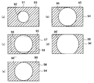
図7はオートズーム処理時の表示を説明するための説明図である。オートズーム処理においては、撮像画像中から被写体画像部分を切出し、モニタのサイズに合わせてサイズを変更した後、モニタに出力する。図7(a)は撮像素子23によって得られる撮像画像91を示しており、撮像画像91中には被写体画像92が含まれる。撮像画像91中の被写体画像92以外の部分は、例えば黒レベルのマスク領域93である。
オートズーム処理では、被写体画像92を画面一杯に表示するように切出し及びサイズ変更処理が行われる。図7(b)はモニタの表示画面94に表示された出力撮像画像95を示している。出力撮像画像95には、表示画面94の表示範囲一杯に被写体画像92に基づく拡大画像96が表示されている。
ところが、モニタは、一般的に各種表示モード(スキャンモード)を備えており、必ずしもモニタのスキャン範囲が表示画面の全表示範囲に一致するとは限らない。例えば、表示範囲がスキャン範囲よりも狭いことがある。図7(c)はモニタのこのようなスキャンモードを示しており、実線の四角はスキャン範囲97を示し、破線の四角は表示画面94中の表示範囲98を示している。オートズーム処理では、モニタのスキャン範囲全体に出力撮像画像を表示することを前提に、切出し及びサイズ変更処理が行われている。従って、図7(b)の出力撮像画像95がモニタに入力されると、図7(c)に示すように、被写体画像92に基づく拡大画像96は表示範囲98をはみ出してしまい、図7(d)に示すように、表示画面94上には、一部が欠けた拡大画像96’が表示されてしまう。
そこで、本実施の形態においては、ズーム倍率設定部84が設けられている。画像メモリ45からの映像信号はオートズーム処理部82及びマスク検知部83に供給される。マスク検知部83は入力された映像信号の輝度の変化によって、撮像画像中の被写体画像以外の部分をマスク領域として検知し、検知結果をズーム倍率設定部84に出力する。オートズーム処理部82は、ズーム倍率設定部84によってズーム倍率が設定され、設定されたズーム倍率に応じた切出し範囲で入力画像を切出して出力する。
本実施の形態においては、ズーム倍率設定部84には、図示しないモニタからスキャンモード情報が入力されるようになっている。スキャンモード情報は、モニタスキャンモードを示す情報であって、モニタの現在のスキャン範囲を示す情報を含む。
ズーム倍率設定部84は、マスク検知部83の出力とモニタからのスキャンモード情報とに基づいて、オートズーム処理時に被写体画像に基づく拡大画像のサイズが最大で、拡大画像の全てが表示範囲内で表示されるように、オートズーム処理の切出し範囲を決定するためのズーム倍率(最大ズーム倍率)を求めて、オートズーム処理部82に出力するようになっている。
次に、このように構成された実施の形態の動作について説明する。ズーム倍率設定部84にはマスク検知部83からのマスク検知結果及び図示しないモニタからのスキャンモード情報が入力される。ズーム倍率設定部84は、オートズーム処理部82による切出し範囲を決定するためのズーム倍率を、マスク検知結果及びスキャンモード情報に基づいて決定する。ズーム倍率設定部84からのズーム倍率の情報はオートズーム処理部82に供給されるオートズーム処理部82は、設定されたズーム倍率に応じた切出し範囲で入力画像から被写体画像部分を切出し、モニタの表示画面に応じてサイズに変更して出力する。
これにより、図7(e)に示すように、表示画面94に表示される出力撮像画像99中には、表示画面94の表示範囲98一杯に、被写体画像92に基づく拡大画像96’’が欠けることなく表示される。
このように、本実施の形態においては、モニタからのスキャンモード情報に基づいて切出し範囲を決定していることから、モニタのスキャンモードに拘わらず、常に被写体画像を表示画面一杯に表示させることができる。
(変形例)
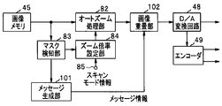
図8は変形例を示すブロック図である。図8は一部の構成のみを示しており、メッセージ生成部101及び画像重畳部102を付加した点が図6の装置と異なるのみである。第2の実施の形態における内視鏡用画像生成装置は、被写体画像を自動的に表示画面一杯にズーム処理するオートズーム処理機能を有する。しかし、内視鏡の径によっては、接眼部15から得られる被写体光学像のサイズが撮像素子23の撮像領域よりも大きいことがある。また、機械的な精度が低い場合には、撮像領域の中心から被写体光学像の中心が大きくずれて、被写体光学像の一部が撮像素子23の撮像領域からはみ出してしまうことも考えられる。これらの場合には、撮像素子23は被写体光学像の一部に基づく画像を得ることはできず、オートズーム処理は行われない。しかし、ユーザには、オートズーム処理が行われない理由が不明である。
図8は変形例を示すブロック図である。図8は一部の構成のみを示しており、メッセージ生成部101及び画像重畳部102を付加した点が図6の装置と異なるのみである。第2の実施の形態における内視鏡用画像生成装置は、被写体画像を自動的に表示画面一杯にズーム処理するオートズーム処理機能を有する。しかし、内視鏡の径によっては、接眼部15から得られる被写体光学像のサイズが撮像素子23の撮像領域よりも大きいことがある。また、機械的な精度が低い場合には、撮像領域の中心から被写体光学像の中心が大きくずれて、被写体光学像の一部が撮像素子23の撮像領域からはみ出してしまうことも考えられる。これらの場合には、撮像素子23は被写体光学像の一部に基づく画像を得ることはできず、オートズーム処理は行われない。しかし、ユーザには、オートズーム処理が行われない理由が不明である。
そこで、本変形例においては、メッセージ生成部101は、マスク検知部83の検知結果に基づいて、オートズーム処理が不能か否かを判定し、オートズーム処理が不能な場合には、その旨を示すメッセージを生成してユーザに提示するようになっている。
例えば、メッセージ生成部101は、撮像領域の上端1ライン、下端の1ライン、左端の1列及び右端の1列中の全ての画素の輝度が所定の黒レベル以下である場合にのみオートズーム可能であると判断してもよい。即ち、メッセージ生成部101は、撮像領域の上下端の2ライン、左右端の2列中の全画素のうちの1つ以上の画素の輝度が所定の黒レベルを超えた場合には、当該画素が被写体画像に含まれる画素であり、撮像素子23からは、被写体光学像の一部が欠けた撮像画像しか得られないものと判断して、オートズーム不能の判定結果を得る。
メッセージ生成部101は、オートズーム不能と判定した場合には、例えば、図示しないモニタ上にオートズームが無効であることを示す表示を表示させるためのメッセージ情報を出力する。このメッセージ情報は、画像重畳部102に与えられる。画像重畳部102は、オートズーム処理部82の出力画像にメッセージの表示データを重畳して出力する。
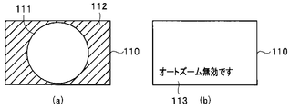
図9はメーセージ表示を説明するための説明図である。図9(a)はオートズーム処理可能の場合に、モニタの表示画面110上に表示される出力撮像画像112を示している。出力撮像画像112には、表示範囲一杯に被写体光学像111が表示されている。一方、図9(b)はオートズーム不能と判定された場合の表示を示しており、表示画面110上には、「オートズーム無効です」というメッセージ表示113が表示されている。このメッセージ表示113によって、ユーザは、カメラヘッド20に装着されている内視鏡では、オートズーム不能であることを認識することができる。
このように本変形例では、マスク検知結果に基づいてオートズーム処理可能か否かを判定して、不能の場合はメッセージ表示を表示させるようになっており、ユーザはメッセージ表示によってオートズーム不能であることを認識することができる。
本発明は、上記各実施形態にそのまま限定されるものではなく、実施段階ではその要旨を逸脱しない範囲で構成要素を変形して具体化できる。また、上記各実施形態に開示されている複数の構成要素の適宜な組み合わせにより、種々の発明を形成できる。例えば、実施形態に示される全構成要素の幾つかの構成要素を削除してもよい。さらに、異なる実施形態にわたる構成要素を適宜組み合わせてもよい。
また、ここで説明した技術のうち、主にフローチャートで説明した制御や機能は、多くがプログラムにより設定可能であり、そのプログラムをコンピュータが読み取り実行することで上述した制御や機能を実現することができる。そのプログラムは、コンピュータプログラム製品として、フレキシブルディスク、CD-ROM等、不揮発性メモリ等の可搬媒体や、ハードディスク、揮発性メモリ等の記憶媒体に、その全体あるいは一部を記録又は記憶することができ、製品出荷時又は可搬媒体或いは通信回線を介して流通又は提供可能である。利用者は、通信ネットワークを介してそのプログラムをダウンロードしてコンピュータにインストールしたり、あるいは記録媒体からコンピュータにインストールすることで、容易に本実施の形態を実現することができる。
なお、動作フローに関して、便宜上「まず、」、「次に、」等を用いて説明したとしても、この順で実施することが必須であることを意味するものではない。また、これらの動作フローを構成する各ステップは、発明の本質に影響しない部分については、適宜省略も可能であることは言うまでもない。
本出願は、2013年11月21日に日本国に出願された特願2013-241136号を優先権主張の基礎として出願するものであり、上記の開示内容は、本願明細書、請求の範囲、図面に引用されたものとする。
Claims (8)
- 撮像部の撮像面に、内視鏡の接眼部から入射された被写体光学像が結像し、前記被写体光学像に基づく被写体画像を含む撮像信号を得るカメラヘッドからの前記撮像信号が入力され、入力された撮像信号に基づいて表示部に表示可能な出力撮像画像を生成する画像処理部と、
前記出力撮像画像に対する前記被写体画像のサイズを示すズーム倍率の情報を取得するズーム情報取得部と、
前記画像処理部からの前記出力撮像画像の中心と前記被写体画像の中心とのずれ量を算出するずれ量算出部と、
前記ずれ量算出時における第1のズーム倍率と設定される第2のズーム倍率との比と、前記ずれ量算出部が算出した前記ずれ量とに基づいて、前記画像処理部からの前記出力撮像画像の中心と前記被写体画像の中心とのずれを補正するずれ補正量を算出するずれ補正量算出部と、
前記ずれ補正量に基づいて前記被写体画像の中心が前記出力撮像画像の中心に一致するように前記画像処理部からの前記出力撮像画像を補正して前記表示部に出力する位置補正部と
を具備したことを特徴とする内視鏡用画像生成装置。 - 前記位置補正部により補正された前記出力撮像画像中における前記被写体画像の範囲を検知するマスク検知部と、
前記表示部のスキャン範囲を示す情報を取得するスキャン情報取得部と、
前記マスク検知部の検知結果及び前記スキャン範囲を示す情報に基づいて、前記出力撮像画像に対する前記被写体画像の最大のズーム倍率を設定する自動ズーム設定部と
を具備したことを特徴とする請求項1に記載の内視鏡用画像生成装置。 - 前記マスク検知部の検知結果及び前記スキャン範囲を示す情報に基づいて、前記自動ズーム設定部によるズーム処理が不能であると判定した場合には、オーズズーム処理が不能であることを示す表示を前記表示部に表示させるメッセージ生成部
を具備したことを特徴とする請求項2に記載の内視鏡用画像生成装置。 - 前記ズーム倍率は、ユーザ操作に基づいて任意の倍率に設定可能である
ことを特徴とする請求項1乃至3のいずれか1つに記載の内視鏡用画像生成装置。 - 前記位置補正部は、
前記画像処理部からの前記出力撮像画像を記憶する画像メモリと、
前記ずれ補正量に基づいて前記画像メモリからの読み出しを制御するメモリ制御部と
を具備したことを特徴とする請求項1乃至4のいずれか1つに記載の内視鏡用画像生成装置。 - 撮像部の撮像面に、内視鏡の接眼部から入射された被写体光学像が結像し、前記被写体光学像に基づく被写体画像を含む撮像信号を得るカメラヘッドからの前記撮像信号が入力され、入力された撮像信号に基づいて表示部に表示可能な出力撮像画像を生成する画像処理ステップと、
前記出力撮像画像に対する前記被写体画像のサイズを示すズーム倍率の情報を取得するズーム情報取得ステップと、
前記画像処理ステップによって得られた前記出力撮像画像の中心と前記被写体画像の中心とのずれ量を算出するずれ量算出ステップと、
前記ずれ量算出時における第1のズーム倍率と変化した第2のズーム倍率との比と、前記ずれ量算出ステップにおいて算出された前記ずれ量とに基づいて、前記画像処理ステップによって得られた前記出力撮像画像の中心と前記被写体画像の中心とのずれを補正するずれ補正量を算出し、算出した前記ずれ補正量に基づいて前記被写体画像の中心が前記出力撮像画像の中心に一致するように前記画像処理ステップによって得られた前記出力撮像画像を補正して前記表示部に出力する位置補正ステップと
を具備したことを特徴とする内視鏡用画像生成方法。 - 前記位置補正ステップは、
前記ずれ量算出ステップによって得られた前記ずれ量に基づいて、前記被写体画像の中心が前記出力撮像画像の中心に一致するように前記画像処理ステップによって得られた前記出力撮像画像を補正して前記表示部に出力し、
前記ズーム倍率に変化があったか否かを判定し、
前記ズーム倍率に変化があった場合には、前記ずれ量算出時における第1のズーム倍率と変化した第2のズーム倍率との比と、前記ずれ量算出ステップにおいて算出された前記ずれ量とに基づいて、前記出力撮像画像の中心と前記被写体画像の中心とのずれを補正するずれ補正量を算出し、算出した前記ずれ補正量に基づいて前記被写体画像の中心が前記出力撮像画像の中心に一致するように前記画像処理ステップによって得られた前記出力撮像画像を補正して前記表示部に出力する
ことを特徴とする請求項6に記載の内視鏡用画像生成方法。 - 前記ずれ量算出ステップは、ホワイトバランス調整時に行われる
ことを特徴とする請求項6又は7に記載の内視鏡用画像生成方法。
Applications Claiming Priority (2)
| Application Number | Priority Date | Filing Date | Title |
|---|---|---|---|
| JP2013241136 | 2013-11-21 | ||
| JP2013-241136 | 2013-11-21 |
Publications (1)
| Publication Number | Publication Date |
|---|---|
| WO2015076293A1 true WO2015076293A1 (ja) | 2015-05-28 |
Family
ID=53179553
Family Applications (1)
| Application Number | Title | Priority Date | Filing Date |
|---|---|---|---|
| PCT/JP2014/080624 Ceased WO2015076293A1 (ja) | 2013-11-21 | 2014-11-19 | 内視鏡用画像生成装置及び内視鏡用画像生成方法 |
Country Status (1)
| Country | Link |
|---|---|
| WO (1) | WO2015076293A1 (ja) |
Cited By (1)
| Publication number | Priority date | Publication date | Assignee | Title |
|---|---|---|---|---|
| CN110786813A (zh) * | 2019-11-22 | 2020-02-14 | 珠海视新医用科技有限公司 | 一种内窥镜 |
Citations (4)
| Publication number | Priority date | Publication date | Assignee | Title |
|---|---|---|---|---|
| JPH11299727A (ja) * | 1998-04-24 | 1999-11-02 | Olympus Optical Co Ltd | 内視鏡装置 |
| JP2001327466A (ja) * | 2000-05-24 | 2001-11-27 | Olympus Optical Co Ltd | 内視鏡システム |
| JP2004065316A (ja) * | 2002-08-01 | 2004-03-04 | Olympus Corp | 内視鏡装置 |
| JP4309605B2 (ja) * | 2001-05-25 | 2009-08-05 | 株式会社東芝 | オートセンタリング機能を有する撮像装置 |
-
2014
- 2014-11-19 WO PCT/JP2014/080624 patent/WO2015076293A1/ja not_active Ceased
Patent Citations (4)
| Publication number | Priority date | Publication date | Assignee | Title |
|---|---|---|---|---|
| JPH11299727A (ja) * | 1998-04-24 | 1999-11-02 | Olympus Optical Co Ltd | 内視鏡装置 |
| JP2001327466A (ja) * | 2000-05-24 | 2001-11-27 | Olympus Optical Co Ltd | 内視鏡システム |
| JP4309605B2 (ja) * | 2001-05-25 | 2009-08-05 | 株式会社東芝 | オートセンタリング機能を有する撮像装置 |
| JP2004065316A (ja) * | 2002-08-01 | 2004-03-04 | Olympus Corp | 内視鏡装置 |
Cited By (1)
| Publication number | Priority date | Publication date | Assignee | Title |
|---|---|---|---|---|
| CN110786813A (zh) * | 2019-11-22 | 2020-02-14 | 珠海视新医用科技有限公司 | 一种内窥镜 |
Similar Documents
| Publication | Publication Date | Title |
|---|---|---|
| US9538108B2 (en) | Endoscope system and pixel correction method | |
| EP2926717B1 (en) | Endoscope system | |
| JP6104493B1 (ja) | 撮像システム | |
| JP6401800B2 (ja) | 画像処理装置、画像処理装置の作動方法、画像処理装置の作動プログラムおよび内視鏡装置 | |
| JP6045760B2 (ja) | 撮像システム | |
| JP5379930B1 (ja) | 内視鏡システム | |
| CN103889302A (zh) | 内窥镜系统 | |
| JP6600362B2 (ja) | 内視鏡装置及び内視鏡装置の作動方法 | |
| JP2008043742A (ja) | 電子内視鏡システム | |
| JP2013048694A (ja) | 内視鏡装置 | |
| WO2017221507A1 (ja) | 内視鏡システム | |
| US11419482B2 (en) | Endoscope apparatus, control method of endoscope apparatus, and recording medium | |
| JP2014228851A (ja) | 内視鏡装置、画像取得方法および画像取得プログラム | |
| JP6238618B2 (ja) | 内視鏡画像処理装置及び内視鏡装置 | |
| WO2015076293A1 (ja) | 内視鏡用画像生成装置及び内視鏡用画像生成方法 | |
| JP2011024901A (ja) | 電子内視鏡システムおよび調光信号補正方法 | |
| JP5959331B2 (ja) | 内視鏡装置 | |
| JP6082658B2 (ja) | 撮像素子および内視鏡装置 | |
| JP5827868B2 (ja) | 電子内視鏡及び固定パターンノイズ除去方法 | |
| JP2007190060A (ja) | 内視鏡装置 | |
| JP5985117B1 (ja) | 撮像装置、画像処理装置、撮像装置の作動方法 | |
| JP4674093B2 (ja) | 内視鏡装置及びプログラム | |
| JP5211703B2 (ja) | プロジェクタ | |
| JP6172738B2 (ja) | 電子内視鏡および電子内視鏡システム | |
| JP2000338535A (ja) | 写真撮影装置 |
Legal Events
| Date | Code | Title | Description |
|---|---|---|---|
| 121 | Ep: the epo has been informed by wipo that ep was designated in this application |
Ref document number: 14864295 Country of ref document: EP Kind code of ref document: A1 |
|
| NENP | Non-entry into the national phase |
Ref country code: DE |
|
| 122 | Ep: pct application non-entry in european phase |
Ref document number: 14864295 Country of ref document: EP Kind code of ref document: A1 |
|
| NENP | Non-entry into the national phase |
Ref country code: JP |