WO2015076132A1 - 軸シール装置、回転機械、及び軸シール装置の製造方法 - Google Patents
軸シール装置、回転機械、及び軸シール装置の製造方法 Download PDFInfo
- Publication number
- WO2015076132A1 WO2015076132A1 PCT/JP2014/079690 JP2014079690W WO2015076132A1 WO 2015076132 A1 WO2015076132 A1 WO 2015076132A1 JP 2014079690 W JP2014079690 W JP 2014079690W WO 2015076132 A1 WO2015076132 A1 WO 2015076132A1
- Authority
- WO
- WIPO (PCT)
- Prior art keywords
- leaf
- side end
- seal plate
- end portion
- shaft
- Prior art date
- Legal status (The legal status is an assumption and is not a legal conclusion. Google has not performed a legal analysis and makes no representation as to the accuracy of the status listed.)
- Ceased
Links
Images


Classifications
-
- F—MECHANICAL ENGINEERING; LIGHTING; HEATING; WEAPONS; BLASTING
- F01—MACHINES OR ENGINES IN GENERAL; ENGINE PLANTS IN GENERAL; STEAM ENGINES
- F01D—NON-POSITIVE DISPLACEMENT MACHINES OR ENGINES, e.g. STEAM TURBINES
- F01D11/00—Preventing or minimising internal leakage of working-fluid, e.g. between stages
- F01D11/001—Preventing or minimising internal leakage of working-fluid, e.g. between stages for sealing space between stator blade and rotor
-
- F—MECHANICAL ENGINEERING; LIGHTING; HEATING; WEAPONS; BLASTING
- F16—ENGINEERING ELEMENTS AND UNITS; GENERAL MEASURES FOR PRODUCING AND MAINTAINING EFFECTIVE FUNCTIONING OF MACHINES OR INSTALLATIONS; THERMAL INSULATION IN GENERAL
- F16J—PISTONS; CYLINDERS; SEALINGS
- F16J15/00—Sealings
- F16J15/16—Sealings between relatively-moving surfaces
- F16J15/32—Sealings between relatively-moving surfaces with elastic sealings, e.g. O-rings
- F16J15/3284—Sealings between relatively-moving surfaces with elastic sealings, e.g. O-rings characterised by their structure; Selection of materials
- F16J15/3292—Lamellar structures
-
- F—MECHANICAL ENGINEERING; LIGHTING; HEATING; WEAPONS; BLASTING
- F05—INDEXING SCHEMES RELATING TO ENGINES OR PUMPS IN VARIOUS SUBCLASSES OF CLASSES F01-F04
- F05D—INDEXING SCHEME FOR ASPECTS RELATING TO NON-POSITIVE-DISPLACEMENT MACHINES OR ENGINES, GAS-TURBINES OR JET-PROPULSION PLANTS
- F05D2220/00—Application
- F05D2220/30—Application in turbines
- F05D2220/32—Application in turbines in gas turbines
-
- F—MECHANICAL ENGINEERING; LIGHTING; HEATING; WEAPONS; BLASTING
- F05—INDEXING SCHEMES RELATING TO ENGINES OR PUMPS IN VARIOUS SUBCLASSES OF CLASSES F01-F04
- F05D—INDEXING SCHEME FOR ASPECTS RELATING TO NON-POSITIVE-DISPLACEMENT MACHINES OR ENGINES, GAS-TURBINES OR JET-PROPULSION PLANTS
- F05D2240/00—Components
- F05D2240/55—Seals
- F05D2240/57—Leaf seals
-
- F—MECHANICAL ENGINEERING; LIGHTING; HEATING; WEAPONS; BLASTING
- F05—INDEXING SCHEMES RELATING TO ENGINES OR PUMPS IN VARIOUS SUBCLASSES OF CLASSES F01-F04
- F05D—INDEXING SCHEME FOR ASPECTS RELATING TO NON-POSITIVE-DISPLACEMENT MACHINES OR ENGINES, GAS-TURBINES OR JET-PROPULSION PLANTS
- F05D2240/00—Components
- F05D2240/55—Seals
- F05D2240/59—Lamellar seals
-
- F—MECHANICAL ENGINEERING; LIGHTING; HEATING; WEAPONS; BLASTING
- F05—INDEXING SCHEMES RELATING TO ENGINES OR PUMPS IN VARIOUS SUBCLASSES OF CLASSES F01-F04
- F05D—INDEXING SCHEME FOR ASPECTS RELATING TO NON-POSITIVE-DISPLACEMENT MACHINES OR ENGINES, GAS-TURBINES OR JET-PROPULSION PLANTS
- F05D2240/00—Components
- F05D2240/60—Shafts
-
- F—MECHANICAL ENGINEERING; LIGHTING; HEATING; WEAPONS; BLASTING
- F05—INDEXING SCHEMES RELATING TO ENGINES OR PUMPS IN VARIOUS SUBCLASSES OF CLASSES F01-F04
- F05D—INDEXING SCHEME FOR ASPECTS RELATING TO NON-POSITIVE-DISPLACEMENT MACHINES OR ENGINES, GAS-TURBINES OR JET-PROPULSION PLANTS
- F05D2250/00—Geometry
- F05D2250/10—Two-dimensional
- F05D2250/18—Two-dimensional patterned
- F05D2250/181—Two-dimensional patterned ridged
-
- F—MECHANICAL ENGINEERING; LIGHTING; HEATING; WEAPONS; BLASTING
- F05—INDEXING SCHEMES RELATING TO ENGINES OR PUMPS IN VARIOUS SUBCLASSES OF CLASSES F01-F04
- F05D—INDEXING SCHEME FOR ASPECTS RELATING TO NON-POSITIVE-DISPLACEMENT MACHINES OR ENGINES, GAS-TURBINES OR JET-PROPULSION PLANTS
- F05D2250/00—Geometry
- F05D2250/10—Two-dimensional
- F05D2250/18—Two-dimensional patterned
- F05D2250/182—Two-dimensional patterned crenellated, notched
-
- F—MECHANICAL ENGINEERING; LIGHTING; HEATING; WEAPONS; BLASTING
- F05—INDEXING SCHEMES RELATING TO ENGINES OR PUMPS IN VARIOUS SUBCLASSES OF CLASSES F01-F04
- F05D—INDEXING SCHEME FOR ASPECTS RELATING TO NON-POSITIVE-DISPLACEMENT MACHINES OR ENGINES, GAS-TURBINES OR JET-PROPULSION PLANTS
- F05D2250/00—Geometry
- F05D2250/10—Two-dimensional
- F05D2250/18—Two-dimensional patterned
- F05D2250/184—Two-dimensional patterned sinusoidal
-
- F—MECHANICAL ENGINEERING; LIGHTING; HEATING; WEAPONS; BLASTING
- F05—INDEXING SCHEMES RELATING TO ENGINES OR PUMPS IN VARIOUS SUBCLASSES OF CLASSES F01-F04
- F05D—INDEXING SCHEME FOR ASPECTS RELATING TO NON-POSITIVE-DISPLACEMENT MACHINES OR ENGINES, GAS-TURBINES OR JET-PROPULSION PLANTS
- F05D2250/00—Geometry
- F05D2250/20—Three-dimensional
- F05D2250/24—Three-dimensional ellipsoidal
- F05D2250/241—Three-dimensional ellipsoidal spherical
-
- F—MECHANICAL ENGINEERING; LIGHTING; HEATING; WEAPONS; BLASTING
- F05—INDEXING SCHEMES RELATING TO ENGINES OR PUMPS IN VARIOUS SUBCLASSES OF CLASSES F01-F04
- F05D—INDEXING SCHEME FOR ASPECTS RELATING TO NON-POSITIVE-DISPLACEMENT MACHINES OR ENGINES, GAS-TURBINES OR JET-PROPULSION PLANTS
- F05D2250/00—Geometry
- F05D2250/20—Three-dimensional
- F05D2250/28—Three-dimensional patterned
-
- F—MECHANICAL ENGINEERING; LIGHTING; HEATING; WEAPONS; BLASTING
- F05—INDEXING SCHEMES RELATING TO ENGINES OR PUMPS IN VARIOUS SUBCLASSES OF CLASSES F01-F04
- F05D—INDEXING SCHEME FOR ASPECTS RELATING TO NON-POSITIVE-DISPLACEMENT MACHINES OR ENGINES, GAS-TURBINES OR JET-PROPULSION PLANTS
- F05D2250/00—Geometry
- F05D2250/70—Shape
- F05D2250/71—Shape curved
- F05D2250/711—Shape curved convex
-
- F—MECHANICAL ENGINEERING; LIGHTING; HEATING; WEAPONS; BLASTING
- F05—INDEXING SCHEMES RELATING TO ENGINES OR PUMPS IN VARIOUS SUBCLASSES OF CLASSES F01-F04
- F05D—INDEXING SCHEME FOR ASPECTS RELATING TO NON-POSITIVE-DISPLACEMENT MACHINES OR ENGINES, GAS-TURBINES OR JET-PROPULSION PLANTS
- F05D2250/00—Geometry
- F05D2250/70—Shape
- F05D2250/71—Shape curved
- F05D2250/712—Shape curved concave
Definitions
- the present invention relates to a shaft seal device, a rotary machine, and a method for manufacturing the shaft seal device.
- a shaft sealing device that seals the periphery of a rotating shaft as disclosed in Patent Document 1 is known in rotating machines such as gas turbines, steam turbines, and compressors.
- the shaft sealing device disclosed in Patent Document 1 includes a plurality of leaves (thin plates) disposed around a rotation shaft, and side seal plates (each disposed in a high-pressure space and a low-pressure space divided by the leaves). Side leaf).
- leaves thin plates
- side seal plates each disposed in a high-pressure space and a low-pressure space divided by the leaves.
- Side leaf When the rotating shaft is stopped, the tip (inner end) of the leaf is in contact with the outer peripheral surface of the rotating shaft. When the rotating shaft rotates, the leaf tip is displaced away from the rotating shaft, so that the leaf and the rotating shaft are not in contact with each other.
- the side seal plate approaches the side end portion of the leaf due to the action of pressure, and prevents the working gas in the high-pressure space from excessively flowing between the leaves.
- the tip of the leaf may not be able to move away from the rotation shaft when the rotation shaft rotates.
- the rotating shaft rotates while the leaf and the rotating shaft are in contact with each other, the leaf may be worn, and as a result, the sealing performance may be deteriorated.
- An object of the present invention is to provide a shaft seal device, a rotary machine, and a method for manufacturing the shaft seal device, in which a decrease in performance is suppressed.
- the shaft sealing device includes a leaf that is arranged in a plurality around the rotating shaft, divides the space around the rotating shaft into two spaces with respect to the axial direction of the rotating shaft, and one side of the leaf with respect to the axial direction And a side seal plate having a facing surface facing the one side end of the leaf, wherein at least one of the leaf and the side seal plate is formed between the facing surface and the side end. It has a friction reduction part which reduces the frictional force with the surface.
- the side seal plate even when the side seal plate is pressed against the side end portion of the leaf, at least one of the leaf and the side seal plate has the friction reducing portion that reduces the frictional force between the opposing surface and the surface of the side end portion. Therefore, the side seal plate can be prevented from blocking the displacement of the tip of the leaf. Therefore, at the time of rotation of the rotating shaft, the tip of the leaf smoothly moves away from the rotating shaft and is in a non-contact state with the rotating shaft. Therefore, the rotation of the rotating shaft while the leaf and the rotating shaft are in contact with each other is suppressed, and the deterioration of the sealing performance is suppressed.
- the friction reducing portion may include a low friction coefficient film formed on at least one of the facing surface and the surface of the side end portion. For example, by applying at least one of plating, thermal spraying, and vapor deposition to the opposing surface of the side seal plate to form a highly lubricious film, the frictional force between the opposing surface and the surface of the side edge is reduced. can do.
- the friction reducing portion may be formed by texturing on at least one of the opposing surface and the surface of the side end portion. For example, by applying a texturing process such as sand blasting to the opposing surface of the side seal plate to form a dimple or lattice-like micro level uneven surface, the contact area between the opposing surface and the surface of the side edge portion Therefore, the frictional force between the facing surface and the surface of the side end can be reduced.
- a texturing process such as sand blasting
- the friction reduction unit may include a concave surface or a convex surface formed on at least one of the surface of the facing surface and the side end. For example, by making the surface of the side end portion of the leaf convex, the contact area between the facing surface and the surface of the side end portion is reduced, so that the frictional force between the facing surface and the surface of the side end portion can be reduced. it can.
- a shaft seal device includes a rotating shaft and the above-described shaft sealing device disposed around the rotating shaft.
- the shaft sealing device described above since the shaft sealing device described above is provided, a reduction in sealing performance is suppressed. Therefore, a rotating machine with a long life and good maintainability is provided.
- a method for manufacturing a shaft seal device is a method for manufacturing a shaft seal device comprising a leaf and a side seal plate disposed to face a side end portion of the leaf, and the side end of the leaf Performing a friction reduction process for reducing the frictional force between the facing surface and the surface of the side end portion on at least one of the surface of the portion and the facing surface of the side seal plate facing the side end portion; Arranging a plurality of the leaves around the rotation axis, and dividing the space around the rotation axis into two spaces with respect to the axial direction of the rotation axis; Disposing the side seal plate so that the one side end portion and the facing surface face each other.
- the side seal plate even when the side seal plate is pressed against the side end portion of the leaf, at least one of the surface of the side end portion of the leaf and the opposing surface of the side seal plate is between the opposing surface and the surface of the side end portion. Since the friction reducing process for reducing the frictional force is performed, the side seal plate can be prevented from blocking the displacement of the tip of the leaf. Therefore, at the time of rotation of the rotating shaft, the tip of the leaf smoothly moves away from the rotating shaft and is in a non-contact state with the rotating shaft. Therefore, the rotation of the rotating shaft while the leaf and the rotating shaft are in contact with each other is suppressed, and the deterioration of the sealing performance is suppressed.
- FIG. 1 is a diagram illustrating an example of a gas turbine system according to the first embodiment.
- FIG. 2 is a cross-sectional view schematically showing the shaft seal device according to the first embodiment.
- FIG. 3 is a perspective view schematically showing a part of the shaft seal device according to the first embodiment.
- FIG. 4 is a cross-sectional view schematically illustrating the shaft seal device according to the first embodiment.
- FIG. 5 is an exploded view of the shaft seal device according to the first embodiment.
- FIG. 6 is a diagram illustrating the high-pressure side seal plate according to the first embodiment.
- FIG. 7 is a pressure distribution diagram of the working gas formed in the gap between the leaves according to the first embodiment.
- FIG. 8 is a diagram showing a cross section of the body portion of the leaf according to the first embodiment and the pressure acting on the body portion using vectors.
- FIG. 9 is a diagram illustrating an example of the shaft seal device according to the first embodiment.
- FIG. 10 is a flowchart illustrating an example of a manufacturing method of the shaft seal device according to the first embodiment.
- FIG. 11 is a diagram illustrating an example of a facing surface according to the second embodiment.
- FIG. 12 is a diagram illustrating an example of a facing surface according to the second embodiment.
- FIG. 13 is a schematic diagram illustrating an example of a leaf and a high-pressure side seal plate according to the third embodiment.
- FIG. 14 is a schematic diagram illustrating an example of a leaf and a high-pressure side seal plate according to the third embodiment.
- FIG. 15 is a schematic diagram illustrating an example of a leaf and a high-pressure side seal plate according to the third embodiment.
- FIG. 1 is a diagram illustrating an example of a gas turbine system 1 having a rotating machine according to the present embodiment.
- the gas turbine system 1 includes a compressor 2, a combustor 3, a turbine 4, and a rotor 5 including a rotating shaft 50.
- the rotating machine includes at least one of the compressor 2 and the turbine 4.
- Compressor 2 compresses the introduced air.
- the compressor 2 has a casing 2K. Air is introduced into the internal space of the casing 2K.
- the combustor 3 mixes fuel with the compressed air compressed by the compressor 2 and burns it.
- the turbine 4 introduces and expands the combustion gas generated in the combustor 3 and converts the thermal energy of the combustion gas into rotational energy.
- the turbine 4 has a casing 4K. Combustion gas is introduced into the internal space of the casing 4K.
- the rotor 5 includes a rotating shaft 50, and a moving blade 51A and a moving blade 52A provided on the rotating shaft 50.
- the moving blade 51A is provided in the portion 51 of the rotating shaft 50 disposed in the internal space of the casing 2K.
- the moving blade 52A is provided in the portion 52 of the rotating shaft 50 disposed in the internal space of the casing 4K.
- the compressor 2 has a stationary blade 2A disposed in the casing 2K.
- the moving blades 51 ⁇ / b> A and the stationary blades 2 ⁇ / b> A are alternately arranged in a direction (axial direction) parallel to the axis AX of the rotating shaft 50.
- the turbine 4 has a stationary blade 4A disposed in the casing 4K.
- the moving blades 52 ⁇ / b> A and the stationary blades 4 ⁇ / b> A are alternately arranged in the axial direction of the rotating shaft 50.
- the combustion gas introduced from the combustor 3 is supplied to the moving blade 52A.
- the thermal energy of the combustion gas is converted into mechanical rotational energy to generate power.
- Part of the power generated in the turbine 4 is transmitted to the compressor 2 via the rotating shaft 50.
- a part of the power generated in the turbine 4 is used as power for the compressor 2.
- the gas turbine system 1 includes a support portion 2 ⁇ / b> S that is disposed in the compressor 2 and includes a bearing that rotatably supports the rotating shaft 50, and a bearing that is disposed in the turbine 4 and rotatably supports the rotating shaft 50. And a support portion 4S.
- the gas turbine system 1 includes a shaft seal device 10 that seals the periphery of the rotary shaft 50.
- the shaft seal device 10 is disposed in each of the compressor 2 and the turbine 4.
- the shaft seal device 10 disposed in the compressor 2 prevents the compressed air that is the working gas G from leaking from the high pressure side to the low pressure side.
- the shaft seal device 10 of the compressor 2 is disposed on the inner peripheral portion of the stationary blade 2A.
- the shaft seal device 10 of the compressor 2 is disposed on the support portion 2S.
- the shaft seal device 10 disposed in the turbine 4 prevents the combustion gas, which is the working gas G, from leaking from the high pressure side to the low pressure side.
- the shaft seal device 10 of the turbine 4 is disposed on the inner peripheral portion of the stationary blade 4A. Further, the shaft seal device 10 of the turbine 4 is disposed in the support portion 4S.
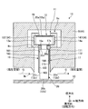
- FIG. 2 is a sectional view schematically showing the shaft seal device 10 according to the present embodiment.
- FIG. 2 corresponds to a cross-sectional view taken along line AA in FIG.
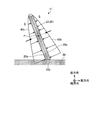
- FIG. 3 is a perspective view schematically showing a part of the shaft seal device 10 according to the present embodiment.
- FIG. 3 is a partially cutaway view of the shaft seal device 10.
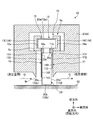
- FIG. 4 is a cross-sectional view schematically showing the shaft sealing device 10 including the axis AX of the rotating shaft 50.
- FIG. 5 is an exploded view of the shaft seal device 10.
- the shaft seal device 10 provided in the turbine 4 among the shaft seal devices 10 provided in each of the compressor 2 and the turbine 4 will be described.
- the structure of the shaft seal device 10 provided in the compressor 2 is equivalent to the structure of the shaft seal device 10 provided in the turbine 4.
- the shaft seal device 10 has a plurality of seal segments 11 arranged around the rotating shaft 50.
- Each of the seal segments 11 has an arc shape in a plane orthogonal to the axis AX.
- eight seal segments 11 are arranged around the rotation shaft 50.
- the seal segment 11 includes a plurality of leaves (thin plates) 20 arranged around the rotation shaft 50 and one side of the leaf 20 with respect to the axial direction of the rotation shaft 50. Holding including the arranged high-pressure side seal plate 16, the low-pressure side seal plate 17 arranged on the other side of the leaf 20 with respect to the axial direction of the rotating shaft 50, the holding ring 13 holding the leaf 20, and the holding ring 14. A member 134 and a back spacer 15 disposed between the leaf 20 and the holding member 134 are provided.
- the seal segment 11 is inserted into the housing 9.
- the housing 9 corresponds to at least one of the stationary blade 2A, the support portion 2S, the stationary blade 4A, and the support portion 4S.
- the housing 9 has a recess 9a.
- the recess 9 a has an opening 9 k that faces the outer peripheral surface of the rotating shaft 50.
- At least a part of the seal segment 11 is disposed in the recess 9 a of the housing 9.
- the recess 9 a extends in the circumferential direction of the rotation shaft 50. A part of the leaf 20 protrudes outside the recess 9a.
- the leaf 20 is a flexible plate-like member.
- the leaf 20 is elastically deformable.
- the leaf 20 is a thin steel plate.
- the normal line of the surface of the leaf 20 is substantially parallel to the circumferential direction (rotation direction) of the rotation shaft 50.
- the width direction of the leaf 20 substantially coincides with the axial direction of the rotation shaft 50.
- the thickness direction of the leaf 20 substantially coincides with the circumferential direction of the rotating shaft 50.
- the leaf 20 has flexibility in the circumferential direction of the rotation shaft 50.
- the leaf 20 has high rigidity in the axial direction of the rotation shaft 50.
- a plurality of the leaves 20 are arranged at intervals in the circumferential direction of the rotating shaft 50.
- a gap S is formed between the leaf 20 and the leaf 20 adjacent to the leaf 20.
- the leaf laminate 12 is formed by the plurality of leaves 20.
- the leaf laminate 12 is an aggregate (laminate) of a plurality of leaves 20.
- the plurality of leaves 20 divides the space around the rotation shaft 50 into two spaces in the axial direction of the rotation shaft 50 by sealing the periphery of the rotation shaft 50.
- the plurality of leaves 20 divide the space around the rotation shaft 50 into a high pressure space and a low pressure space. The pressure in the high pressure space is higher than the pressure in the low pressure space.
- Each of the plurality of leaves 20 includes an outer proximal end portion (outer end portion) 20a, an inner distal end portion (inner end portion) 20b, and a rotation shaft 50 in a radial direction (radial direction) with respect to the axis AX of the rotation shaft 50.
- the side end portion 20c on the high-pressure space side and the side end portion 20d on the low-pressure space side are provided with respect to the axial direction.
- the proximal end portions 20a of the plurality of leaves 20 are appropriately referred to as the proximal end portion 12a of the leaf laminate 12, and the distal end portions 20b of the plurality of leaves 20 are appropriately combined to appropriately define the leaf laminate 12.
- This is referred to as a side end portion 12d of the body 12.
- the base end portion 12a is an aggregate of a plurality of base end portions 20a.
- the tip portion 12b is an aggregate of a plurality of tip portions 20b.
- the side end portion 12c is an aggregate of a plurality of side end portions 20c.
- the side end portion 12d is an aggregate of a plurality of side end portions 20d.
- the base end portion 12a faces outward in the radial direction.
- the distal end portion 12b faces inward in the radial direction so as to face the outer peripheral surface of the rotation shaft 50.
- the side end portion 12 c faces one side (high-pressure space side) with respect to the axial direction of the rotation shaft 50.
- the side end 12d faces the other side (low pressure space side) with respect to the axial direction of the rotating shaft 50.
- the tip portion 12b (tip portion 20b) is disposed outside the recess 9a through the opening 9k.
- each of the base end portions 20a of the plurality of leaves 20 is fixed to the back spacer 15.
- each of the front end portions 20b of the plurality of leaves 20 is not fixed. That is, in this embodiment, the base end part 20a is a fixed end, and the front-end
- the plurality of leaves 20 (leaf laminated body 12) are held by the holding member 134 in a state where the base end portion 20a is fixed.
- the leaf 20 has a head portion 21 and a trunk portion 22.
- the proximal end portion 20 a is disposed on the head portion 21.
- the distal end portion 20 b, the side end portion 20 c, and the side end portion 20 d are disposed on the trunk portion 22.
- the dimension of the trunk portion 22 in the width direction is smaller than the dimension of the head portion 21.
- the dimension of the trunk portion 22 in the thickness direction is smaller than the dimension of the head portion 21.
- the trunk 22 has a notch 20x and a notch 20y at the boundary between the trunk 22 and the head 21.
- the plurality of leaves 20 are connected by welding at each of the side protrusion 21c and the side protrusion 21d of the head 21.
- the trunk portion 22 is elastically deformable.
- the holding member 134 holds the leaf laminate 12.
- the holding member 134 is supported by the housing 9.
- the housing 9 has a support surface 9s inside the recess 9a.
- the holding member 134 is supported by the support surface 9s.
- the holding member 134 includes the holding ring 13 and the holding ring 14.
- Each of the holding ring 13 and the holding ring 14 is an arc-shaped member extending in the circumferential direction of the rotation shaft 50.
- the holding ring 13 has a recess 13 a in which a part of the head 21 including the side protrusion 21 c of the leaf 20 is disposed.
- the holding ring 14 has a recess 14 a in which a part of the head 21 including the side protrusion 21 d of the leaf 20 is disposed.
- the back spacer 15 is disposed between the head 21 of the leaf 20 and the holding ring 13 and the holding ring 14.
- the head 21 of the leaf 20 is fitted into the recess 13a and the recess 14b through the back spacer 15. As a result, the leaf laminate 12 is held by the holding member 134.
- the high-pressure side side seal plate 16 is disposed in the high-pressure space so as to be adjacent to the leaf 20 (leaf laminate 12).
- the low-pressure side side seal plate 17 is disposed in the low-pressure space so as to be adjacent to the leaf 20 (leaf laminated body 12).
- the high-pressure side seal plate 16 is disposed so as to face a part of the side end 12c of the leaf laminate 12 in the high-pressure space.
- the low-pressure side side seal plate 17 is disposed so as to face a part of the side end portion 12d of the leaf laminate 12 in the low-pressure space.
- the high-pressure side side seal plate 16 includes a facing surface 161 that faces at least a part of the side end portion 20c of the leaf 20 (side end portion 12c of the leaf laminate 12), and a surface 162 that faces the opposite direction of the facing surface 161.
- the low-pressure side side seal plate 17 includes a facing surface 171 that faces at least a part of the side end portion 20d of the leaf 20 (side end portion 12d of the leaf laminate 12), and a surface 172 that faces the opposite direction of the facing surface 171.
- the high-pressure side seal plate 16 has a convex portion 16 a that is disposed in the cutout portion 20 x of the leaf 20.
- the convex portion 16 a arranged in the notch 20 x is fixed by the leaf 20 (leaf laminated body 12) and the holding ring 13.
- the low-pressure side side seal plate 17 has a convex portion 17 a disposed in the cutout portion 20 y of the leaf 20.
- the convex portion 17 a arranged in the notch 20 y is fixed by the leaf 20 (leaf laminated body 12) and the holding ring 14.
- the distal end portion 163 of the high-pressure side seal plate 16 is farther from the rotating shaft 50 than the distal end portion 20b of the leaf 20.
- the high-pressure side seal plate 16 opposes a part of the side end 20c (side end 12c) on the base end 20a side in the radial direction, and the side end 20c (side end 12c) on the distal end 20b side. It does not face part.
- the tip portion 173 of the low-pressure side side seal plate 17 is farther from the rotary shaft 50 than the tip portion 20b of the leaf 20.
- the low-pressure-side side seal plate 17 faces a part of the side end 20d (side end 12d) on the base end 20a side in the radial direction, and the side end 20d (side end 12d) on the tip 20b side. It does not face part.
- the tip 173 of the low-pressure side seal plate 17 is further away from the rotary shaft 50 than the tip 163 of the high-pressure side seal plate 16.
- the dimension of the high-pressure side seal plate 16 is larger than the dimension of the low-pressure side seal plate 17 with respect to the radial direction of the rotary shaft 50.
- FIG. 6 is a view of the high-pressure side seal plate 16 as viewed from the facing surface 161 side.
- the high-pressure side side seal plate 16 is a fan-shaped plate member having flexibility.
- the high-pressure side side seal plate 16 can be elastically deformed.
- the high-pressure side seal plate 16 is a thin steel plate.
- the high-pressure side side seal plate 16 has a friction reducing portion for reducing the frictional force between the facing surface 161 and the surface (side surface) of the side end portion 20c.
- the friction reducing unit reduces the frictional force between the high-pressure side seal plate 16 and the leaf 20.
- the high-pressure side side seal plate 16 is subjected to a friction reduction process for reducing the frictional force with the surface (side surface) of the side end portion 20c.
- the friction reducing portion includes a low friction coefficient film 180 formed on the high-pressure side seal plate 16.
- the friction reduction process includes a process of forming a low-friction coefficient film 180 on the surface (opposing surface) of the base material of the high-pressure side seal plate 16.
- a film 180 is formed on the opposing surface of the steel plate that is the base material of the high-pressure side seal plate 16.
- the facing surface 161 is the surface of the film 180.
- the friction coefficient of the surface of the film 180 with respect to the surface of the side end portion 20 c is smaller than the friction coefficient of the surface of the base material (steel plate) of the high-pressure side seal plate 16.
- the film 180 is formed by subjecting the surface (opposing surface) of the base material of the high-pressure side seal plate 16 to at least one of, for example, plating, spraying, and vapor deposition to form a film 180 having high lubricity.
- the frictional force between the facing surface 161 and the surface of the side end portion 20c can be reduced.
- the film 180 may be, for example, a Cr film formed by a Cr plating process or a carbon film formed by a DLC (diamond-like carbon) coating process.
- the film 180 is formed to have a uniform thickness.
- the thickness of the high-pressure side seal plate 16 is about 0.3 mm
- the thickness of the film 180 may be 0.05 mm or more and 0.1 mm or less. Note that when the film 180 is formed of a material having wear resistance and hardly changes over time, the thickness of the film 180 may be not less than 0.1 mm and not more than 0.3 mm.
- the total of the thickness of the film 180 and the thickness of the base material of the high-pressure side seal plate 16 may be set to 0.1 mm or more and 0.5 mm or less. Thereby, the performance of the high-pressure side seal plate 16 is exhibited. Further, if the total thickness of the membrane 180 and the thickness of the base material of the high-pressure side seal plate 16 is 0.3 mm or more, the strength of the high-pressure side seal plate 16 against swirl (swirl flow) is sufficiently maintained. It is.
- FIG. 7 is a pressure distribution diagram of the working gas G formed in the gap S.
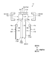
- FIG. 8 is a diagram showing a cross section of the barrel portion 22 that intersects the axis AX of the rotation shaft 50 and the pressure acting on the barrel portion 22 in vector form.
- the tip 20b of the leaf 20 comes into contact with the outer peripheral surface of the rotary shaft 50 with a predetermined preload.
- the gas turbine system 1 is activated and the rotating shaft 50 rotates, the tip 20b of the leaf 20 that is in contact with the outer peripheral surface of the rotating shaft 50 is rubbed against the outer peripheral surface of the rotating shaft 50.
- the tip 20b of the leaf 20 is displaced away from the outer peripheral surface of the rotary shaft 50 due to the dynamic pressure effect generated by the rotation of the rotary shaft 50 (
- the leaf 20 and the rotary shaft 50 are in a non-contact state.
- the working gas G is sealed in a minute gap formed between the leaf 20 and the rotary shaft 50, as shown in FIG.
- the space around the rotating shaft 50 is divided into a high-pressure space and a low-pressure space for the working gas G with the leaf 20 as a boundary. Further, the rotation of the rotary shaft 50 while the leaf 20 and the rotary shaft 50 are not in contact with each other prevents wear of the leaf 20 and the rotary shaft 50.
- At least a part of the working gas G in the high pressure space flows between the tip 20b of the leaf 20 and the outer peripheral surface of the rotating shaft 50 toward the low pressure space. Further, at least a part of the working gas G in the high-pressure space flows into the gap S from a part of the side end portion 20 c that is not opposed to the high-pressure side side seal plate 16. Since the high-pressure side side seal plate 16 faces most of the side end portion 20c, the working gas G in the high-pressure space is prevented from excessively flowing into the gap S.
- the dimension of the high-pressure side seal plate 16 in the radial direction (distance between the tip 163 and the outer peripheral surface of the rotary shaft 50) and the dimension of the low-pressure side seal plate 17 (tip 173 and the rotary shaft 50).
- the size of the low-pressure side seal plate 17 is smaller than the size of the high-pressure side seal plate 16.
- the working gas G that has flowed into the gap S from the high-pressure space flows along the surface of the leaf 20 from the corner r1 of the leaf 20 toward the corner r2.
- the corner r1 is a corner on the tip 20b side and the high-pressure space side.
- the corner r2 is a corner on the base end 20a side and the low-pressure space side.
- the corner r2 is a diagonal of the corner r1.
- each of the plurality of leaves 20 is disposed so as to be inclined with respect to the tangent line of the outer peripheral surface of the rotation shaft 50, so that an arbitrary portion between the proximal end portion 20 a and the distal end portion 20 b of the leaf 20.
- the pressure acting on the surface 20q is higher than the pressure acting on the surface 20p.
- a levitation force FL is generated in the leaf 20 so that the tip 20b of the leaf 20 is separated from the outer peripheral surface of the rotating shaft 50.
- FIG. 9 is a diagram illustrating an example of the shaft seal device 10 according to the present embodiment.
- the seal segment 11 may receive a force from the high pressure space toward the low pressure space, and the low pressure side side seal plate 17 may be in close contact with the housing 9.
- the high-pressure side seal plate 16 may be brought into close contact with the side end 20c of the leaf 20 and pressed with a large force. If the high-pressure side seal plate 16 is pressed against the side end portion 20 c of the leaf 20 with a large force, the distal end portion 20 c of the leaf 20 may not be able to separate from the rotation shaft 50 when the rotation shaft 50 rotates.
- the force with which the high-pressure side seal plate 16 is pressed against the side end 20c of the leaf 20 increases, and as the force increases, the frictional force between the opposing surface 161 and the side end 20c increases.
- the tip 20c of the leaf 20 may not be able to float smoothly from the outer peripheral surface of the rotating shaft 50.
- the opposing surface 161 of the high-pressure side seal plate 16 is formed by the surface of the low-friction coefficient film 180, the opposing surface 161 and the surface of the side end portion 20c (side end portion 12c) are formed. The frictional force is reduced. Therefore, the tip 20c of the leaf 20 can smoothly float from the outer peripheral surface of the rotating shaft 50.
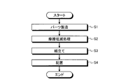
- FIG. 10 is a flowchart illustrating an example of a manufacturing method of the shaft seal device 10 according to the present embodiment.
- the parts constituting the shaft seal device 10 (the leaf 20, the high-pressure side seal plate 16, the low-pressure side seal plate 17, etc.) are manufactured (step S1).
- a friction reducing process is performed on the surface (opposing surface) of the high-pressure side seal plate 16 to reduce the frictional force with the surface of the side end 20c (step S2).
- the friction reduction process includes a process of forming the low-friction coefficient film 180 on the surface (opposing surface) of the base material of the high-pressure side seal plate 16, and includes, for example, a plating process, a thermal spray process, and a vapor deposition process. Including at least one of
- step S3 the leaf 20, the high-pressure side seal plate 16 and the low-pressure side seal plate 17 are assembled, and the seal segment 11 is manufactured (step S3).
- the seal segment 11 is arranged around the rotating shaft 50 (step S4).
- a plurality of the leaves 20 are arranged around the rotation shaft 50, and the space around the rotation shaft 50 is divided into two spaces, a high pressure space and a low pressure space, with respect to the axial direction of the rotation shaft 50.
- the high-pressure side seal plate 16 is arranged on one side (high-pressure space side) of the leaf 20 with respect to the axial direction of the rotary shaft 50 so that the side end 20c of the leaf 20 and the facing surface 161 face each other.
- the low-pressure side seal plate 17 is disposed on the other side (low-pressure space side) of the leaf 20 with respect to the axial direction of the rotary shaft 50 so that the side end 20d of the leaf 20 and the facing surface 171 face each other.
- the entire facing surface 161 may be formed of the film 180, or a part of the facing surface 161 may be formed of the film 180, and a part of the facing surface 161 may be formed of the high-pressure side side seal plate 16. It may be the surface of a base material (steel plate).
- the surface of the side end portion 20c may be formed of a film 180 having a low friction coefficient.
- the opposing surface 171 of the low-pressure side side seal plate 17 may be formed of a low-friction coefficient film 180, or the surface of the side end portion 20d may be formed of a low-friction coefficient film 180.
- the surface 162 of the high-pressure side side seal plate 16 may be formed of a film 180 having a low friction coefficient
- the surface 172 of the low-pressure side side seal plate 17 may be formed of a film 180 having a low friction coefficient.
- the high-pressure side seal plate 16 even when the high-pressure side seal plate 16 is pressed against the side end portion 20c of the leaf 20, at least one of the leaf 20 and the high-pressure side seal plate 16 is opposed to the opposing surface 161. Since the friction reducing process is performed to reduce the frictional force between the front end 20c and the surface of the side end 20c, it is possible to prevent the high-pressure side seal plate 16 from preventing displacement (floating) of the tip 20b of the leaf 20. it can. Therefore, when the rotating shaft 50 rotates, the tip 20c of the leaf 20 moves smoothly away from the rotating shaft 50 and is in a non-contact state with the rotating shaft 50. Therefore, the rotation of the rotation shaft 50 while the leaf 20 and the rotation shaft 50 are in contact with each other is suppressed, and the deterioration of the sealing performance is suppressed.
- the friction reduction process is a process in which at least one of the surfaces of the opposing surface 161 and the side end 20c is the surface of the low friction coefficient film 180, and the friction reduction part has a low friction coefficient.
- a membrane 180 is included. For example, by forming at least one of plating, thermal spraying, and vapor deposition on the surface of the high-pressure side seal plate 16 to form a film 180 having high lubricity, the opposing surface 161 and the surface of the side end 20c The frictional force can be reduced.
- the friction reduction process includes a process of texturing the opposing surface 161 of the high-pressure side seal plate 16.
- the friction reducing unit that reduces the frictional force between the facing surface 161 (the high-pressure side seal plate 16) and the surface of the side end portion 20c (leaf 20) is opposed by texturing the facing surface 161.
- the uneven surface formed on the surface 161 is included.
- FIG. 11 and FIG. 12 are diagrams showing an example of the opposing surface 161 after being textured.
- the opposing surface 161 of the high-pressure side seal plate 16 may be subjected to a texturing process such as sand blasting, so that the opposing surface 161 may be a dimple-like micro level uneven surface as shown in FIG.
- the opposing surface 161 may be a lattice-like micro level uneven surface.
- the diameter of one dimple may be not less than 1 ⁇ m and not more than 100 ⁇ m.
- the size of one grating may be 1 ⁇ m or more and 100 ⁇ m or less.
- the contact surface between the facing surface 161 and the surface of the side end portion 20c is reduced by texturing the facing surface 161 to form a micro level uneven surface.
- the frictional force between the facing surface 161 and the surface of the side end portion 20c can be reduced.
- the entire facing surface 161 may be textured, a part of the facing surface 161 may be textured, and a part of the facing surface 161 may not be textured.
- the surface of the side end portion 20c may be textured.
- the opposing surface 171 of the low-pressure side side seal plate 17 may be textured, or the surface of the side end 20d may be textured.
- the surface 162 of the high-pressure side seal plate 16 may be textured, or the surface 172 of the low-pressure side seal plate 17 may be textured.
- the friction reduction process includes a process of making the surface of the side end 20c convex.
- the friction reducing portion that reduces the frictional force between the facing surface 161 (the high-pressure side seal plate 16) and the surface of the side end portion 20c (leaf 20) includes the convex surface of the side end portion 20c.
- FIG. 13 is a schematic diagram illustrating an example of the leaf 20 and the high-pressure side side seal plate 16 according to the present embodiment.
- the side end 20 c of the leaf 20 may be a convex surface that swells toward the high-pressure side seal plate 16.
- the convex surface of the side end portion 20c is a curved surface.
- FIG. 14 is a schematic diagram illustrating an example of the leaf 20 and the high-pressure side seal plate 16 according to the present embodiment.
- the side end 20 c of the leaf 20 may be a concave surface away from the high-pressure side side seal plate 16.
- the friction reducing portion includes a concave surface of the side end portion 20 c.
- the concave surface of the side end portion 20c is a curved surface. Also by doing so, the contact area between the facing surface 161 and the surface of the side end portion 20c is reduced, so that the frictional force between the facing surface 161 and the surface of the side end portion 20c can be reduced.
- FIG. 15 is a schematic diagram illustrating an example of the leaf 20 and the high-pressure side seal plate 16 according to the present embodiment.
- the side end 20c of the leaf 20 may include both a convex surface and a concave surface.
- the friction reduction unit includes a convex surface and a concave surface of the side end portion 20 c. Also by doing so, the contact area between the facing surface 161 and the surface of the side end portion 20c is reduced, so that the frictional force between the facing surface 161 and the surface of the side end portion 20c can be reduced.
- the facing surface 161 of the high-pressure side seal plate 16 may include at least one of a concave surface and a convex surface.
- the facing surface 171 of the low-pressure side side seal plate 17 may include at least one of a concave surface and a convex surface
- the surface of the side end portion 20d may include at least one of a concave surface and a convex surface.
Landscapes
- Engineering & Computer Science (AREA)
- General Engineering & Computer Science (AREA)
- Mechanical Engineering (AREA)
- Turbine Rotor Nozzle Sealing (AREA)
- Sealing Devices (AREA)
- Structures Of Non-Positive Displacement Pumps (AREA)
Priority Applications (4)
| Application Number | Priority Date | Filing Date | Title |
|---|---|---|---|
| KR1020167010786A KR102100538B1 (ko) | 2013-11-22 | 2014-11-10 | 축 시일 장치, 회전 기계 및 축 시일 장치의 제조 방법 |
| US15/034,319 US10519791B2 (en) | 2013-11-22 | 2014-11-10 | Shaft sealing device, rotating machine, and method for manufacturing shaft sealing device |
| CN201480059280.1A CN105683509B (zh) | 2013-11-22 | 2014-11-10 | 轴密封装置、旋转机械及轴密封装置的制造方法 |
| EP14863444.7A EP3059397B1 (en) | 2013-11-22 | 2014-11-10 | Shaft seal device, rotary machine, and method for manufacturing shaft seal device |
Applications Claiming Priority (2)
| Application Number | Priority Date | Filing Date | Title |
|---|---|---|---|
| JP2013241956A JP6125412B2 (ja) | 2013-11-22 | 2013-11-22 | 軸シール装置、回転機械、及び軸シール装置の製造方法 |
| JP2013-241956 | 2013-11-22 |
Publications (1)
| Publication Number | Publication Date |
|---|---|
| WO2015076132A1 true WO2015076132A1 (ja) | 2015-05-28 |
Family
ID=53179399
Family Applications (1)
| Application Number | Title | Priority Date | Filing Date |
|---|---|---|---|
| PCT/JP2014/079690 Ceased WO2015076132A1 (ja) | 2013-11-22 | 2014-11-10 | 軸シール装置、回転機械、及び軸シール装置の製造方法 |
Country Status (6)
| Country | Link |
|---|---|
| US (1) | US10519791B2 (https=) |
| EP (1) | EP3059397B1 (https=) |
| JP (1) | JP6125412B2 (https=) |
| KR (1) | KR102100538B1 (https=) |
| CN (1) | CN105683509B (https=) |
| WO (1) | WO2015076132A1 (https=) |
Families Citing this family (4)
| Publication number | Priority date | Publication date | Assignee | Title |
|---|---|---|---|---|
| JP7211877B2 (ja) * | 2019-04-11 | 2023-01-24 | 三菱重工業株式会社 | 蒸気タービンロータ及び蒸気タービン |
| CN110067602A (zh) * | 2019-04-23 | 2019-07-30 | 东南大学 | 双前挡板三腔刷式密封结构 |
| US11692449B2 (en) | 2020-02-14 | 2023-07-04 | Raytheon Technologies Corporation | Carbon seal assembly |
| JP7566201B2 (ja) * | 2022-03-04 | 2024-10-11 | 三菱重工業株式会社 | 軸シール装置及び回転機械 |
Citations (7)
| Publication number | Priority date | Publication date | Assignee | Title |
|---|---|---|---|---|
| JP2003343730A (ja) * | 2002-05-23 | 2003-12-03 | Eagle Ind Co Ltd | 板ブラシシール |
| JP2005069404A (ja) * | 2003-08-26 | 2005-03-17 | Nsk Ltd | 密封型転がり軸受 |
| JP2007321986A (ja) * | 2000-09-14 | 2007-12-13 | Research Triangle Inst | マイクロ電気機械システムバルブ及びその製造方法 |
| JP2010507056A (ja) * | 2006-10-20 | 2010-03-04 | アッシュ・ウー・エフ | 潤滑媒体中で200MPaを超える接触圧力において動作する摩擦片 |
| JP2011185219A (ja) | 2010-03-10 | 2011-09-22 | Mitsubishi Heavy Ind Ltd | 軸シール装置及び軸シール装置を備える回転機械 |
| JP2013040682A (ja) * | 2011-08-17 | 2013-02-28 | General Electric Co <Ge> | 自己潤滑性ブラシシール組立体及び漏洩低減方法 |
| JP2013145007A (ja) * | 2012-01-13 | 2013-07-25 | Mitsubishi Heavy Ind Ltd | 軸シール装置及びこれを備える回転機械 |
Family Cites Families (21)
| Publication number | Priority date | Publication date | Assignee | Title |
|---|---|---|---|---|
| GB9801864D0 (en) | 1998-01-30 | 1998-03-25 | Rolls Royce Plc | A seal arrangement |
| EP1070887A3 (en) * | 1999-07-22 | 2002-08-21 | General Electric Company | Brush seal having secured bristles |
| JP3593082B2 (ja) * | 2001-10-09 | 2004-11-24 | 三菱重工業株式会社 | 軸シール機構及びタービン |
| JP4009555B2 (ja) * | 2003-05-20 | 2007-11-14 | イーグル・エンジニアリング・エアロスペース株式会社 | 板ブラシシール装置 |
| CN1324221C (zh) * | 2003-05-21 | 2007-07-04 | 三菱重工业株式会社 | 轴密封机构 |
| CN100396885C (zh) * | 2003-05-21 | 2008-06-25 | 三菱重工业株式会社 | 轴密封机构、轴密封机构的组装结构和大型流体机械 |
| DE102004016173A1 (de) * | 2004-03-30 | 2005-10-20 | Alstom Technology Ltd Baden | Lamellendichtung, insbesondere für eine Gasturbine, sowie Verfahren zu deren Herstellung |
| GB0417613D0 (en) | 2004-08-07 | 2004-09-08 | Rolls Royce Plc | A leaf seal arrangement |
| JP3917993B2 (ja) * | 2004-08-10 | 2007-05-23 | 三菱重工業株式会社 | 軸シール機構及び軸シール機構をステータに取り付ける構造並びにこれらを備えたタービン。 |
| DE102004059858A1 (de) * | 2004-12-11 | 2006-06-29 | Alstom Technology Ltd | Lamellendichtung, insbesondere für eine Gasturbine |
| JP3970298B2 (ja) * | 2005-11-10 | 2007-09-05 | 三菱重工業株式会社 | 軸シール機構 |
| US7419164B2 (en) * | 2006-08-15 | 2008-09-02 | General Electric Company | Compliant plate seals for turbomachinery |
| US7976026B2 (en) * | 2007-04-30 | 2011-07-12 | General Electric Company | Methods and apparatus to facilitate sealing in rotary machines |
| US7744092B2 (en) * | 2007-04-30 | 2010-06-29 | General Electric Company | Methods and apparatus to facilitate sealing in rotary machines |
| US8262349B2 (en) * | 2008-12-22 | 2012-09-11 | General Electric Company | Adaptive compliant plate seal assemblies and methods |
| US8250756B2 (en) * | 2009-02-20 | 2012-08-28 | General Electric Company | Method of manufacture of compliant plate seals |
| DE102009015122A1 (de) * | 2009-03-31 | 2010-10-14 | Alstom Technology Ltd. | Lamellendichtung für eine Strömungsmaschine |
| US8413992B2 (en) * | 2009-06-16 | 2013-04-09 | Mitsubishi Heavy Industries, Ltd. | Shaft seal and rotary machine with same |
| GB0922074D0 (en) * | 2009-12-18 | 2010-02-03 | Rolls Royce Plc | A leaf seal assembly |
| US8474827B2 (en) * | 2010-06-11 | 2013-07-02 | Cmg Tech, Llc | Film riding pressure actuated leaf seal assembly |
| US8382120B2 (en) * | 2010-08-31 | 2013-02-26 | General Electric Company | Method and apparatus for compliant plate seals |
-
2013
- 2013-11-22 JP JP2013241956A patent/JP6125412B2/ja active Active
-
2014
- 2014-11-10 WO PCT/JP2014/079690 patent/WO2015076132A1/ja not_active Ceased
- 2014-11-10 CN CN201480059280.1A patent/CN105683509B/zh not_active Expired - Fee Related
- 2014-11-10 KR KR1020167010786A patent/KR102100538B1/ko not_active Expired - Fee Related
- 2014-11-10 US US15/034,319 patent/US10519791B2/en not_active Expired - Fee Related
- 2014-11-10 EP EP14863444.7A patent/EP3059397B1/en not_active Not-in-force
Patent Citations (7)
| Publication number | Priority date | Publication date | Assignee | Title |
|---|---|---|---|---|
| JP2007321986A (ja) * | 2000-09-14 | 2007-12-13 | Research Triangle Inst | マイクロ電気機械システムバルブ及びその製造方法 |
| JP2003343730A (ja) * | 2002-05-23 | 2003-12-03 | Eagle Ind Co Ltd | 板ブラシシール |
| JP2005069404A (ja) * | 2003-08-26 | 2005-03-17 | Nsk Ltd | 密封型転がり軸受 |
| JP2010507056A (ja) * | 2006-10-20 | 2010-03-04 | アッシュ・ウー・エフ | 潤滑媒体中で200MPaを超える接触圧力において動作する摩擦片 |
| JP2011185219A (ja) | 2010-03-10 | 2011-09-22 | Mitsubishi Heavy Ind Ltd | 軸シール装置及び軸シール装置を備える回転機械 |
| JP2013040682A (ja) * | 2011-08-17 | 2013-02-28 | General Electric Co <Ge> | 自己潤滑性ブラシシール組立体及び漏洩低減方法 |
| JP2013145007A (ja) * | 2012-01-13 | 2013-07-25 | Mitsubishi Heavy Ind Ltd | 軸シール装置及びこれを備える回転機械 |
Non-Patent Citations (2)
| Title |
|---|
| HIDEYUKI INOUE ET AL.: "Mechanical Seal ni Okeru Dimple Kaikokei no Shudo Tokusei eno Eikyo", PROCEEDINGS OF JAST TRIBOLOGY CONFERENCE ( CD-ROM, vol. D1, 23 October 2013 (2013-10-23), pages 1 - 2, XP008182008 * |
| See also references of EP3059397A4 |
Also Published As
| Publication number | Publication date |
|---|---|
| US20160281520A1 (en) | 2016-09-29 |
| JP6125412B2 (ja) | 2017-05-10 |
| EP3059397B1 (en) | 2019-04-24 |
| CN105683509B (zh) | 2017-12-15 |
| CN105683509A (zh) | 2016-06-15 |
| EP3059397A1 (en) | 2016-08-24 |
| EP3059397A4 (en) | 2017-01-04 |
| US10519791B2 (en) | 2019-12-31 |
| KR102100538B1 (ko) | 2020-04-13 |
| KR20160060746A (ko) | 2016-05-30 |
| JP2015101990A (ja) | 2015-06-04 |
Similar Documents
| Publication | Publication Date | Title |
|---|---|---|
| JP5804893B2 (ja) | 軸シール装置及びこれを備える回転機械 | |
| JP5174241B2 (ja) | 軸シール及びこれを備えた回転機械 | |
| EP2546466B1 (en) | Shaft seal device and rotary machine with shaft seal device | |
| JP6125412B2 (ja) | 軸シール装置、回転機械、及び軸シール装置の製造方法 | |
| JP6012505B2 (ja) | 軸シール装置及び回転機械 | |
| EP3159582B1 (en) | Shaft seal device and rotary machine | |
| US20120007317A1 (en) | Axially angled annular seals | |
| KR102240987B1 (ko) | 베어링 장치 및 회전기계 | |
| JP2004162569A (ja) | 軸シール機構及びタービン | |
| WO2017195575A1 (ja) | シールセグメント及び回転機械 | |
| JP2012177420A (ja) | 軸シール機構 | |
| JP6876012B2 (ja) | シールセグメント及び回転機械 | |
| JP2017089441A (ja) | 軸シール機構及び回転機械 | |
| US10927765B2 (en) | Seal segment and rotary machine | |
| WO2016098752A1 (ja) | 軸シール機構 | |
| JP6590522B2 (ja) | シール装置及び回転機械 | |
| JP2017082909A (ja) | フォイル軸受及びこれに用いられるフォイル並びにその製造方法 |
Legal Events
| Date | Code | Title | Description |
|---|---|---|---|
| 121 | Ep: the epo has been informed by wipo that ep was designated in this application |
Ref document number: 14863444 Country of ref document: EP Kind code of ref document: A1 |
|
| ENP | Entry into the national phase |
Ref document number: 20167010786 Country of ref document: KR Kind code of ref document: A |
|
| REEP | Request for entry into the european phase |
Ref document number: 2014863444 Country of ref document: EP |
|
| WWE | Wipo information: entry into national phase |
Ref document number: 2014863444 Country of ref document: EP |
|
| WWE | Wipo information: entry into national phase |
Ref document number: 15034319 Country of ref document: US |
|
| NENP | Non-entry into the national phase |
Ref country code: DE |