WO2015075874A1 - 操作装置 - Google Patents
操作装置 Download PDFInfo
- Publication number
- WO2015075874A1 WO2015075874A1 PCT/JP2014/005503 JP2014005503W WO2015075874A1 WO 2015075874 A1 WO2015075874 A1 WO 2015075874A1 JP 2014005503 W JP2014005503 W JP 2014005503W WO 2015075874 A1 WO2015075874 A1 WO 2015075874A1
- Authority
- WO
- WIPO (PCT)
- Prior art keywords
- switch
- touch
- touch switch
- input surface
- input
- Prior art date
- Legal status (The legal status is an assumption and is not a legal conclusion. Google has not performed a legal analysis and makes no representation as to the accuracy of the status listed.)
- Ceased
Links
Images











Classifications
-
- G—PHYSICS
- G06—COMPUTING OR CALCULATING; COUNTING
- G06F—ELECTRIC DIGITAL DATA PROCESSING
- G06F3/00—Input arrangements for transferring data to be processed into a form capable of being handled by the computer; Output arrangements for transferring data from processing unit to output unit, e.g. interface arrangements
- G06F3/01—Input arrangements or combined input and output arrangements for interaction between user and computer
- G06F3/03—Arrangements for converting the position or the displacement of a member into a coded form
- G06F3/033—Pointing devices displaced or positioned by the user, e.g. mice, trackballs, pens or joysticks; Accessories therefor
- G06F3/0362—Pointing devices displaced or positioned by the user, e.g. mice, trackballs, pens or joysticks; Accessories therefor with detection of one-dimensional [1D] translations or rotations of an operating part of the device, e.g. scroll wheels, sliders, knobs, rollers or belts
-
- B—PERFORMING OPERATIONS; TRANSPORTING
- B60—VEHICLES IN GENERAL
- B60K—ARRANGEMENT OR MOUNTING OF PROPULSION UNITS OR OF TRANSMISSIONS IN VEHICLES; ARRANGEMENT OR MOUNTING OF PLURAL DIVERSE PRIME-MOVERS IN VEHICLES; AUXILIARY DRIVES FOR VEHICLES; INSTRUMENTATION OR DASHBOARDS FOR VEHICLES; ARRANGEMENTS IN CONNECTION WITH COOLING, AIR INTAKE, GAS EXHAUST OR FUEL SUPPLY OF PROPULSION UNITS IN VEHICLES
- B60K35/00—Instruments specially adapted for vehicles; Arrangement of instruments in or on vehicles
- B60K35/10—Input arrangements, i.e. from user to vehicle, associated with vehicle functions or specially adapted therefor
-
- G—PHYSICS
- G06—COMPUTING OR CALCULATING; COUNTING
- G06F—ELECTRIC DIGITAL DATA PROCESSING
- G06F3/00—Input arrangements for transferring data to be processed into a form capable of being handled by the computer; Output arrangements for transferring data from processing unit to output unit, e.g. interface arrangements
- G06F3/01—Input arrangements or combined input and output arrangements for interaction between user and computer
- G06F3/02—Input arrangements using manually operated switches, e.g. using keyboards or dials
- G06F3/023—Arrangements for converting discrete items of information into a coded form, e.g. arrangements for interpreting keyboard generated codes as alphanumeric codes, operand codes or instruction codes
-
- H—ELECTRICITY
- H03—ELECTRONIC CIRCUITRY
- H03K—PULSE TECHNIQUE
- H03K17/00—Electronic switching or gating, i.e. not by contact-making and –breaking
- H03K17/94—Electronic switching or gating, i.e. not by contact-making and –breaking characterised by the way in which the control signals are generated
- H03K17/96—Touch switches
- H03K17/962—Capacitive touch switches
-
- B—PERFORMING OPERATIONS; TRANSPORTING
- B60—VEHICLES IN GENERAL
- B60H—ARRANGEMENTS OF HEATING, COOLING, VENTILATING OR OTHER AIR-TREATING DEVICES SPECIALLY ADAPTED FOR PASSENGER OR GOODS SPACES OF VEHICLES
- B60H1/00—Heating, cooling or ventilating devices
- B60H1/00642—Control systems or circuits; Control members or indication devices for heating, cooling or ventilating devices
- B60H1/0065—Control members, e.g. levers or knobs
-
- B—PERFORMING OPERATIONS; TRANSPORTING
- B60—VEHICLES IN GENERAL
- B60K—ARRANGEMENT OR MOUNTING OF PROPULSION UNITS OR OF TRANSMISSIONS IN VEHICLES; ARRANGEMENT OR MOUNTING OF PLURAL DIVERSE PRIME-MOVERS IN VEHICLES; AUXILIARY DRIVES FOR VEHICLES; INSTRUMENTATION OR DASHBOARDS FOR VEHICLES; ARRANGEMENTS IN CONNECTION WITH COOLING, AIR INTAKE, GAS EXHAUST OR FUEL SUPPLY OF PROPULSION UNITS IN VEHICLES
- B60K2360/00—Indexing scheme associated with groups B60K35/00 or B60K37/00 relating to details of instruments or dashboards
- B60K2360/126—Rotatable input devices for instruments
-
- B—PERFORMING OPERATIONS; TRANSPORTING
- B60—VEHICLES IN GENERAL
- B60K—ARRANGEMENT OR MOUNTING OF PROPULSION UNITS OR OF TRANSMISSIONS IN VEHICLES; ARRANGEMENT OR MOUNTING OF PLURAL DIVERSE PRIME-MOVERS IN VEHICLES; AUXILIARY DRIVES FOR VEHICLES; INSTRUMENTATION OR DASHBOARDS FOR VEHICLES; ARRANGEMENTS IN CONNECTION WITH COOLING, AIR INTAKE, GAS EXHAUST OR FUEL SUPPLY OF PROPULSION UNITS IN VEHICLES
- B60K2360/00—Indexing scheme associated with groups B60K35/00 or B60K37/00 relating to details of instruments or dashboards
- B60K2360/139—Clusters of instrument input devices
-
- B—PERFORMING OPERATIONS; TRANSPORTING
- B60—VEHICLES IN GENERAL
- B60K—ARRANGEMENT OR MOUNTING OF PROPULSION UNITS OR OF TRANSMISSIONS IN VEHICLES; ARRANGEMENT OR MOUNTING OF PLURAL DIVERSE PRIME-MOVERS IN VEHICLES; AUXILIARY DRIVES FOR VEHICLES; INSTRUMENTATION OR DASHBOARDS FOR VEHICLES; ARRANGEMENTS IN CONNECTION WITH COOLING, AIR INTAKE, GAS EXHAUST OR FUEL SUPPLY OF PROPULSION UNITS IN VEHICLES
- B60K2360/00—Indexing scheme associated with groups B60K35/00 or B60K37/00 relating to details of instruments or dashboards
- B60K2360/143—Touch sensitive instrument input devices
- B60K2360/1446—Touch switches
-
- H—ELECTRICITY
- H03—ELECTRONIC CIRCUITRY
- H03K—PULSE TECHNIQUE
- H03K2217/00—Indexing scheme related to electronic switching or gating, i.e. not by contact-making or -breaking covered by H03K17/00
- H03K2217/94—Indexing scheme related to electronic switching or gating, i.e. not by contact-making or -breaking covered by H03K17/00 characterised by the way in which the control signal is generated
- H03K2217/96—Touch switches
- H03K2217/9607—Capacitive touch switches
- H03K2217/960755—Constructional details of capacitive touch and proximity switches
Definitions
- This disclosure relates to an operating device provided with a touch switch.
- an operation device for an in-vehicle device disclosed in Patent Document 1 is provided with a touch switch that detects a change in capacitance generated between a finger and the like.
- the panel portion exposed toward the operator forms the input surface of the touch switch.
- the operator performs input to the touch switch by a contact operation in which a finger touches the input surface.
- the inventor of the present application has developed an operation device that includes a dial portion to which a rotation operation is input and a press switch portion to which a press operation is input in addition to the touch switch.
- the inventor of the present application erroneously detected a rotation operation on the dial portion or a press operation on the press switch portion as a touch operation on the touch switch in a configuration in which the touch switch and the dial portion or the press switch portion are arranged. I found it easy.
- the dial part protrudes from the panel part in the front direction facing the input surface. And the rotation operation to a dial part is input into the cylindrical side surface formed in the dial part. Therefore, it is easy for the operator to move his / her finger to the back side of the cylindrical side surface in an attempt to reliably grip the cylindrical side surface of the dial part. Thus, when the finger is moved to the back side of the cylindrical side surface, there is a possibility that it is difficult to secure the distance between the input surface and the finger touching the cylindrical side surface.
- the present disclosure has been made in view of the above-described problems.
- the purpose of the present disclosure is to make each operation on the dial unit or the press switch unit as a touch operation on the touch switch without impairing the operability of the touch switch.
- An object of the present invention is to provide an operating device capable of avoiding erroneous detection.
- an operating device provided with a touch switch that detects a change in electrostatic capacitance accompanying a contact operation performed by an operating body.
- the operation device has a panel portion that forms an input surface in contact with the operation body among the touch switches, and protrudes from the panel portion in the front direction facing the input surface at a position aligned with the touch switch, so that the rotation operation by the operation body can be performed.
- a dial portion that is input to the cylindrical side surface. Between the input surface and the cylindrical side surface, there is provided a middle step surface that is positioned in front of the input surface and extends to the outer peripheral side of the cylindrical side surface.
- an operator who touches the operating body on the cylindrical side surface of the dial portion inputs the operating body to the far side in order to input a rotation operation to the cylindrical side surface of the dial unit. Even when it is moved, the movement of the operating body to the back side is hindered by the middle step surface extending to the outer peripheral side of the cylindrical side surface. In this way, if the operating body hits the middle stage surface located in the front direction of the input surface between the input surface and the cylindrical side surface, the area of the input surface is maintained so as not to impair the operability of the touch switch. Even if this is maintained, the distance from the operating body touching the cylindrical side surface to the input surface can be secured. Therefore, even if an operating body close to the input surface causes a change in capacitance due to a rotation operation to the dial unit, such a change in capacitance is erroneously detected as a touch switch operation. The situation is avoided.
- an operating device provided with a touch switch that detects a change in capacitance accompanying a contact operation performed by an operating body.
- the operation device has a panel portion that forms an input surface in contact with the operating body among the touch switches, and protrudes from the panel portion in the front direction facing the input surface at a position aligned with the touch switch, and is rotated by the operating body.
- an operation determination unit that determines whether there is a touch operation on the touch switch based on a change in capacitance detected by the touch switch, an input surface and the cylindrical shape
- a detection switch that detects an operating body that is located between the side surface and touches the cylindrical side surface. The operation determination unit does not determine whether there is a touch operation on the touch switch when the detection switch detects the operating body.
- the operation body touching the cylindrical side surface is detected by the detection switch during the input of the rotation operation to the dial unit. I will not. Therefore, even if an operating body close to the input surface causes a change in capacitance due to a rotation operation to the dial unit, such a change in capacitance is erroneously detected as a touch switch operation. The situation is avoided. In addition, even if a detection switch is provided between the input surface and the cylindrical side surface, the area of the input surface can be maintained. Therefore, the operability of the touch switch is ensured.
- an operating device provided with a plurality of touch switches (60) for detecting a change in capacitance accompanying a contact operation performed by the operating body (F).
- the operation device protrudes from the panel unit in the front direction facing the input surface at the position where the input unit comes in contact with the operation body among the touch switches and the plurality of touch switches, and is rotated by the operation body.
- a dial unit that inputs an operation to the cylindrical side surface, and an operation determination unit that determines whether or not there is a touch operation on the touch switch based on a change in capacitance detected by each touch switch.
- the operation determination unit makes the sensitivity of the first touch switch closest to the dial unit among the plurality of touch switches lower than the sensitivity of the second touch switch separated from the dial unit than the first touch switch. .
- an operating device provided with a plurality of touch switches that detect a change in capacitance accompanying a contact operation performed by an operating body.
- the panel part that forms the input surface that comes into contact with the operating body, and at the position along with the multiple touch switches, it projects beyond the panel part in the front direction facing the input surface, and the rotating operation by the operating body is cylindrical A dial portion that is input to the side surface.
- the sensitivity of the first touch switch closest to the dial portion among the plurality of touch switches is lower than the sensitivity of the second touch switch (562) farther from the dial portion than the first touch switch.
- Sensitivity reduction structures (670, 770, 870, 970) are provided.
- the sensitivity of the first touch switch closest to the dial unit is controlled by the operation determination unit or the sensitivity lowering structure of the second touch switch farther from the dial unit than the first touch switch. It is lower than the sensitivity. Therefore, even if the operating body close to the input surface causes a change in capacitance due to the rotation operation to the dial part, such a change in capacitance is erroneously detected as a contact operation to the first touch switch. This situation is avoided.
- the area of the input surface can be maintained if the sensitivity of the first touch switch is lowered by the control by the operation determination unit or the sensitivity reduction structure. Therefore, the operability of the touch switch is ensured.
- an operating device provided with a touch switch that detects a change in capacitance accompanying a contact operation performed by an operating body.
- the operating device protrudes from the panel portion in the front direction facing the input surface at a position aligned with the touch switch and the panel portion that forms the input surface in contact with the operating body among the touch switches.
- An input pressure switch unit is provided between the input surface and the press switch part. Between the input surface and the press switch part, a middle step surface located in the front direction from the input surface is provided.
- the operation device of the present disclosure even when an operator who has touched the operating body with the pressing switch unit moves the operating body to the back side in order to input a pressing operation to the pressing switch unit, The movement to the back side of the body is hindered by the middle step surface located between the press switch part and the input surface. In this way, if the operating body hits the middle surface located in front of the input surface, the touch switch can be touched even if the area of the input surface is maintained so as not to impair the operability of the touch switch. The distance from the operating body to the input surface can be ensured. Therefore, even if an operating body close to the input surface causes a change in capacitance due to a pressing operation on the pressing switch unit, such a change in capacitance is erroneously detected as a touch switch touch operation. This situation is avoided.
- an operating device provided with a touch switch that detects a change in capacitance accompanying a contact operation performed by an operating body.
- the operating device protrudes from the panel portion in the front direction facing the input surface at a position aligned with the touch switch at a position aligned with the touch switch, and a pressing operation by the operating body.
- the operation determination unit that determines whether there is a contact operation to the touch switch based on the change in capacitance detected by the touch switch, And a detection switch that detects an operating body that is located between and touching the pressing switch unit.
- the operation determining unit does not determine whether there is a touch operation on the touch switch when the detection switch detects the operating body.
- the operating device of the present disclosure during the input of the pressing operation to the pressing switch unit, since the operating body touching the pressing switch unit is detected by the detection switch, it is determined that there is a touch operation on the touch switch. I will not. Therefore, even if an operating body close to the input surface causes a change in capacitance due to a pressing operation on the pressing switch unit, such a change in capacitance is erroneously detected as a touch switch touch operation. This situation is avoided. In addition, even if a detection switch is provided between the input surface and the pressing switch unit, the area of the input surface can be maintained. Therefore, the operability of the touch switch is ensured.
- an operating device provided with a plurality of touch switches that detect a change in capacitance accompanying a contact operation performed by an operating body.
- the operation device protrudes from the panel unit in the front direction facing the input surface at a position aligned with the touch panel and a panel unit that forms an input surface in contact with the operation body among the touch switches, and is pressed by the operation body.
- the operation determination unit makes the sensitivity of the first touch switch closest to the pressing switch unit among the plurality of touch switches lower than the sensitivity of the second touch switch separated from the pressing switch unit than the first touch switch. .
- an operating device provided with a plurality of touch switches that detect a change in capacitance accompanying a contact operation performed by an operating body.
- the operation device protrudes from the panel unit in the front direction facing the input surface at a position aligned with the touch panel and a panel unit that forms an input surface in contact with the operation body among the touch switches, and is pressed by the operation body.
- a press switch unit to which an operation is input.
- a sensitivity lowering structure that lowers the sensitivity of the first touch switch closest to the pressing switch portion among the plurality of touch switches to be lower than the sensitivity of the second touch switch separated from the pressing switch portion than the first touch switch, Provided.
- the sensitivity of the first touch switch closest to the pressing switch unit is more separated from the pressing switch unit than the first touch switch by the control by the operation determination unit or the sensitivity reduction structure.
- the sensitivity of the switch is lower. Therefore, even if an operating body that is close to the input surface causes a change in capacitance due to a pressing operation on the pressing switch unit, such a change in capacitance is erroneously detected as a touch operation on the first touch switch. The situation that is done is avoided.
- the area of the input surface can be easily maintained if the sensitivity of the first touch switch is lowered by the control by the operation determination unit or the sensitivity reduction structure. Therefore, the operability of the touch switch is ensured.
- the operation device of the present disclosure it is possible to avoid erroneously detecting each operation on the dial unit or the pressing switch unit as a touch operation on the touch switch without impairing the operability of the touch switch.
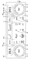
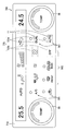
- FIG. 1 is a front view of an operating device according to a first embodiment of the present disclosure.
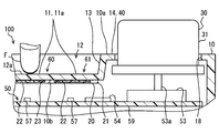
- the FIG. 2 is a diagram showing the structure around the dial knob, and is a cross-sectional view taken along the line II-II in FIG.
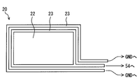
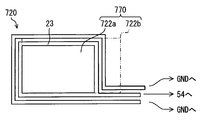
- the FIG. 3 is a diagram schematically showing the shape of the transparent electrode and the wiring portion provided in the film sensor
- FIG. 4 is a block diagram showing an electrical configuration of the operating device
- FIG. 5 is a diagram for explaining the principle that the capacitance value detected by the closest switch decreases due to the formation of the recess
- FIG. 1 is a front view of an operating device according to a first embodiment of the present disclosure.
- the FIG. 2 is a diagram showing the structure around the dial knob, and is a cross-sectional view taken along the line II-II in FIG.
- the FIG. 3 is a diagram schematically showing the shape of the transparent electrode and the wiring portion provided in the film sensor
- FIG. 4 is a block diagram showing an electrical configuration of the operating device
- FIG. 6 is a front view of the operating device according to the second embodiment of the present disclosure
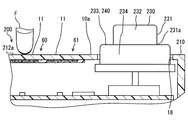
- 7 is a cross-sectional view taken along line VII-VII in FIG.
- FIG. 8 is a front view of the operating device according to the third embodiment of the present disclosure
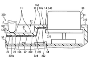
- 9 is a cross-sectional view taken along the line IX-IX in FIG.
- FIG. 10 is a flowchart illustrating an operation determination process performed by the operation determination unit.
- FIG. 11 is a front view of the operating device according to the fourth embodiment of the present disclosure
- 12 is a cross-sectional view taken along line XII-XII of FIG.
- FIG. 13 is a front view of the operating device according to the fifth embodiment of the present disclosure;
- FIG. 11 is a front view of the operating device according to the fourth embodiment of the present disclosure
- 12 is a cross-sectional view taken along line XII-XII of FIG.
- FIG. 13 is a front view of the operating device according to the fifth embodiment of the present
- FIG. 14 is a diagram comparing the first threshold value and the second threshold value set in the operation determination unit
- FIG. 15 is a timing chart for explaining each delay time and monitoring time set in the operation determination unit.
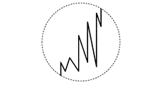
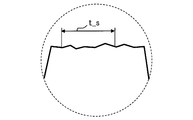
- FIG. 16 is a diagram illustrating a change in capacitance caused by a contact operation by an operator along an elapsed time from the start of the operation
- FIG. 17 is an enlarged view of a region XVII in FIG.
- FIG. 18 is an enlarged view of region XVIII in FIG.
- FIG. 19 is a flowchart illustrating an operation determination process performed by the operation determination unit.
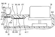
- FIG. 20 is a view showing a structure around a dial knob of the operating device according to the sixth embodiment, FIG.
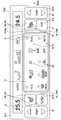
- FIG. 21 is a front view of the operating device according to the seventh embodiment of the present disclosure
- FIG. 22 is a diagram schematically illustrating the shape of the transparent electrode and the wiring portion provided in the film sensor according to the seventh embodiment.
- FIG. 23 is a diagram schematically showing the shapes of the transparent electrode and the wiring portion provided in the film sensor according to the eighth embodiment.
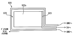
- FIG. 24 is a diagram schematically showing the shape of the transparent electrode and the wiring portion provided in the film sensor according to the ninth embodiment
- FIG. 25 is a front view of the operating device according to the tenth embodiment of the present disclosure
- 26 is a diagram showing the structure around the mechanical switch, and is a cross-sectional view taken along the line XXVI-XXVI of FIG.
- FIG. 27 is a block diagram showing an electrical configuration of the operating device
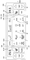
- FIG. 28 is a front view of the operating device according to the eleventh embodiment of the present disclosure
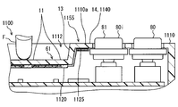
- 29 is a sectional view taken along line XXIX-XXIX in FIG.
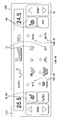
- FIG. 30 is a front view of an operating device according to a twelfth embodiment of the present disclosure
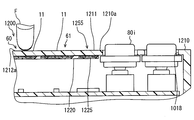
- 31 is a sectional view taken along line XXXI-XXI in FIG.
- FIG. 32 is a front view of an operating device according to a thirteenth embodiment of the present disclosure
- FIG. 33 is a diagram illustrating a structure around a mechanical switch of the operating device according to the fourteenth embodiment of the present disclosure
- FIG. 34 is a front view of the operating device according to the fifteenth embodiment of the present disclosure.
- the operation device 100 forms a user interface for operating an air conditioner 90 (corresponding to an associated device of the present disclosure) mounted on a vehicle.
- the operation device 100 is installed on an instrument panel in a vehicle cabin, and exposes the plurality of touch switches 60 and the two dial knobs 30 in a range where an operator's finger F (see FIG. 2) can be easily reached.
- the operator can operate the operating state of the air conditioner 90 by inputting to the touch switch 60 and the dial knob 30.
- the operating state of the air conditioner 90 is notified to the operator by the display unit 17 provided in the operation device 100.
- the operating device 100 includes an operating panel 10, a film sensor 20, a dial knob 30, a control circuit 50, and the like.
- the direction in which the front surface that the finger F contacts on the operation panel 10 faces is the front direction, and the direction opposite to the front direction is the back direction.
- the operation panel 10 is formed, for example, by applying a light-shielding paint or printing with a light-shielding ink to a light-transmitting resin material that is generally plate-shaped.
- two dial openings 18 and one display opening 19 are formed.
- the dial opening 18 is a circular through hole through which the dial knob 30 is inserted.
- the display opening 19 is a rectangular through hole for enabling the display unit 17 of the liquid crystal display 58 arranged in the depth direction of the operation panel 10 to be visible to the operator.
- the operation panel 10 is provided with a recess 12 and a protrusion 13.
- the recess 12 is formed between two dial openings 18 arranged in the horizontal direction.
- the concave portion 12 is formed by denting a rectangular region at the center of the operation panel 10 in the back direction with respect to the reference surface portion 10a of the operation panel 10 in which each dial side surface 31 is opened.
- a plurality of input surfaces 11 are formed on the bottom wall surface 12 a of the recess 12.
- the input surface 11 is a part of the touch switch 60 and is a part of the touch switch 60 that contacts the finger F.
- the input surface 11 has a planar shape along the reference surface portion 10a.
- Each input surface 11 is formed with an icon 11 a that abstracts the function assigned to each touch switch 60.
- the icon 11a is formed by translucent coating or printing applied in place of light-shielding coating or printing, and is lit and displayed by the transmission of light in the front direction.
- the protruding portion 13 is a portion protruding from the outer edge of the input surface 11 toward the front surface, and includes a reference surface portion 10a around the dial opening 18.
- the top surface 14 of the protrusion 13 that is a part of the reference surface portion 10 a forms a step of about several millimeters (mm) with the input surface 11.
- the width of the top surface 14 in the horizontal direction is desirably secured at a minimum of about 5 to 10 mm.
- the film sensor 20 is formed in a film shape, and is attached to the back surface 10b located on the opposite side of the input surface 11 in the operation panel 10 by a double-sided tape or an adhesive.
- the film sensor 20 includes an insulating film 21, a transparent electrode 22, a wiring part 23, and the like.
- the insulating film 21 is formed of a light-transmitting thin film material such as polyethylene terephthalate or polyimide.
- the transparent electrode 22 is a translucent conductive layer formed by a conductive polymer paint (for example, poly (3,4-ethylenedioxythiophene) (PEDOT)) applied to the insulating film 21.
- a plurality of transparent electrodes 22 are arranged so as to overlap each icon 11a.
- the transparent electrode 22 generates capacitance between the finger F touching the input surface 11.
- the capacitance generated between the finger F and the transparent electrode 22 changes according to the distance from the input surface 11 to the finger F.
- a material for forming the transparent electrode for example, indium tin oxide, a metal film material having a large number of light transmitting holes opened, a printing material containing a conductive substance such as carbon, etc. can be adopted. is there.
- the wiring part 23 is formed of a film material such as metal.
- the wiring part 23 extends in a strip shape so as to go around the transparent electrode 22.
- Two wiring portions 23 are provided for one transparent electrode 22.
- One of the two wiring parts 23 located on the inner peripheral side and surrounding the outer edge of the transparent electrode 22 is electrically connected to a later-described capacitance measuring part 54 of the control circuit 50.
- the other wiring portion 23 located on the outer peripheral side is grounded to the ground through the control circuit 50.
- the dial knob 30 shown in FIGS. 1 and 2 is formed in a cylindrical shape by a hard material such as resin and metal. Each dial knob 30 is inserted into each dial opening 18 in a posture in which the axial direction is substantially orthogonal to the reference surface portion 10a. The dial knob 30 protrudes in the front direction from the reference surface portion 10 a at a position along with the touch switch 60. A rotation operation by the finger F is input to a dial side surface 31 formed in a cylindrical shape in the dial knob 30. The outer diameter of the dial side surface 31 is slightly smaller than the inner diameter of the dial opening 18. The dial knob 30 can be rotated on both sides in the circumferential direction by a rotation operation input to the dial side surface 31.
- the circuit board 59 is formed in a rectangular plate shape, and is disposed in the back direction of the operation panel 10 in a posture along the plate surface direction of the operation panel 10.
- the capacitance measuring unit 54 measures the capacitance at each transparent electrode 22 from the signal acquired from each transparent electrode 22.
- the operation determination unit 52 determines whether there is a touch operation on the touch switch based on a change in capacitance detected by the touch switch. That is, the operation determination unit 52 acquires the capacitance value of each transparent electrode 22 calculated by the capacitance measurement unit 54, and the acquired capacitance value is a preset threshold value Cth (FIG. 5). Compare).
- the operation determination unit 52 determines the presence / absence of a touch operation to each touch switch 60 based on the comparison result, and outputs the determination result to the control unit 51.
- the rotation detector 53 is, for example, a rotary volume, and is mounted on the circuit board (only one is shown in FIG. 5).
- the rotation detection unit 53 rotatably supports the dial knob 30 with a rotation shaft 53a.
- the rotation detection unit 53 detects a rotation operation input to the dial knob 30 and outputs a signal corresponding to the input rotation direction and rotation amount to the control unit 51.
- the control unit 51 includes a microcomputer that operates based on a program.
- the control unit 51 is connected to the control unit of the air conditioner 90 and can exchange information with each other.
- the control unit 51 acquires information related to the contact operation and the rotation operation input by the operator from the operation determination unit 52 and the rotation detection unit 53, and outputs a signal instructing the change of the operation state to the air conditioner 90. .
- the control unit 51 acquires a signal indicating the current operating state from the air conditioner 90.
- control unit 51 is connected to a plurality of light sources 57 and the liquid crystal display 58 described above.
- the light source 57 is a light emitting diode, for example, and is mounted on the front surface of the circuit board 59.
- Each light source 57 is arranged in the back direction of each touch switch 60, and displays each icon 11a by light emitted toward the front surface.
- the control unit 51 controls the light emission of each light source 57.
- the control unit 51 controls the liquid crystal display 58 based on information acquired from the air conditioner 90 and causes the display unit 17 to display the current operating state of the air conditioner 90.
- the middle surface 40 is provided between the input surface 11 and the dial side surface 31.
- the middle step surface 40 in the first embodiment is formed by the top surface 14 of the operation panel 10.
- the middle stage surface 40 is located in the front direction from the input surface 11, and extends in a planar shape along the input surface 11 to the outer peripheral side of the dial side surface 31.
- Equation 1 ⁇ is a dielectric constant of a substance existing between the finger F and the transparent electrode 22.
- S is an area where the finger F and the transparent electrode 22 overlap.
- D is the distance between the finger F and the transparent electrode 22.
- the finger F touching the dial side surface 31 is very close to the closest switch 61. Therefore, since the distance d in Formula 1 is reduced, the capacitance measured by the closest switch 61 due to the finger F touching the dial side surface 31 becomes equal to or greater than the threshold Cth.
- the input surface 11 is moved away from the dial side surface 31 by the concave portion 12, and the further proximity of the finger F is prevented by the middle surface 40.
- the distance d in Equation 1 is ensured. Therefore, the electrostatic capacitance measured by the closest switch 61 due to the finger F touching the dial side surface 31 is greatly below the threshold value Cth.
- the middle step surface 40 in the first embodiment is formed by the operation panel 10 among the dial knob 30 and the operation panel 10.
- the middle step surface 40 does not rotate with the dial knob 30. Therefore, the operator avoids the finger F from being in close contact with the middle surface 40. Therefore, the function of the middle step surface 40 that prevents the movement to the back side is further ensured, and the distance from the finger F to the input surface 11 can be ensured. Therefore, the situation in which the closest change switch 61 erroneously detects the change in the capacitance accompanying the rotation operation as the contact operation is further reduced.
- the finger F corresponds to the “operation body” of the present disclosure
- the operation panel 10 corresponds to the “panel portion” of the present disclosure
- the dial knob 30 corresponds to the “dial portion” of the present disclosure.
- the dial side surface 31 corresponds to the “cylindrical side surface” of the present disclosure
- the air conditioner 90 corresponds to “device” of the present disclosure.
- the second embodiment of the present disclosure shown in FIGS. 6 and 7 is a modification of the first embodiment.
- the recessed part 12 (refer FIG. 2) is abbreviate
- the dial knob 230 of the second embodiment is formed in a two-stage columnar shape, and has a small diameter portion 232 and a large diameter portion 234.
- the outer diameter of the small diameter portion 232 is smaller than the outer diameter of the large diameter portion 234.
- the small diameter portion 232 is arranged coaxially with the large diameter portion 234 and is located in the front direction of the large diameter portion 234.
- the small-diameter portion 232 forms a cylindrical dial side surface 231 that is assumed to be input for a rotation operation by the finger F.
- the dial side surface 231 corresponds to the dial side surface 31 (see FIG. 2) of the first embodiment.
- the outer diameter of the large diameter portion 234 is slightly smaller than the inner diameter of the dial opening 18.
- the large diameter portion 234 forms an enlarged surface 233.
- the enlarged surface 233 is an end surface of the large-diameter portion 234 that faces the front surface direction.
- the enlarged surface 233 is an annular flat surface that extends from the edge portion 231a located in the back direction to the outer peripheral side, of both edges of the dial side surface 231.
- the width of the enlarged surface 233 in the radial direction is, for example, about several mm.
- a step of about 5 mm is formed between the enlarged surface 233 and the reference surface portion 10a.
- the level difference between the enlarged surface 233 and the reference surface portion 10a is suppressed to such an extent that it is difficult to grip the side surface of the large diameter portion 234 with the finger F.
- the enlarged surface 233 positioned between the input surface 11 and the dial side surface 231 forms a middle step surface 240 corresponding to the middle step surface 40 (see FIG. 2) of the first embodiment. Therefore, even when the operator who has touched the finger F on the dial side surface 231 moves the finger F further in the back direction, the movement of the finger F is performed from the edge portion 231a in the back direction of the dial side surface 231 to the outer peripheral side. It is blocked by the expanding middle step surface 240.
- the finger F hits the middle step surface 240, the distance from the finger F touching the dial side surface 231 to the input surface 11 is secured. Therefore, the capacitance detected by the closest switch 61 when the finger F is touching the dial side surface 231 is reduced.
- the middle step surface 240 is formed on the dial knob 230, the recess 12 (see FIG. 2) can be omitted from the operation panel 210. Therefore, the area of the switch region 212a in which the plurality of input surfaces 11 are formed is further ensured. Therefore, the operability of the touch switch 60 can be maintained higher and the false detection can be reduced.
- the operation panel 210 corresponds to the “panel portion” of the present disclosure
- the dial knob 230 corresponds to the “dial portion” of the present disclosure
- the dial side surface 231 corresponds to the “tubular side surface” of the present disclosure. It corresponds to.
- the third embodiment of the present disclosure shown in FIGS. 8 and 9 is another modification of the first embodiment.
- a detection switch 355 is provided between the dial side surface 31 and the input surface 11.
- the detection switch 355 is a capacitance type sensor that is substantially the same as the touch switch 60 and is provided to detect the finger F touching the dial side surface 31.
- the detection switch 355 includes a region where the middle surface 340 is formed on the operation panel 310, an extension region 325 of the film sensor 320, and the like.
- the middle step surface 340 corresponds to the middle step surface 40 (see FIG. 2) of the first embodiment, and is formed by the top surface 14 of the protruding portion 13.
- the middle surface 340 is provided in a region closer to the recess 12 than the center of the dial knob 30 in the reference surface portion 10a.
- the middle surface 340 extends to the outer peripheral side of the dial knob 30.
- the extension region 325 is connected to the main body region 320 a of the film sensor 320 by the extension wiring portion 324.
- the main body region 320a is a region attached to the back surface 10b side of the bottom wall surface 12a in the film sensor 320.
- a transparent electrode 322 and a wiring portion 323 that are substantially the same as the transparent electrode 22 and the wiring portion 23 provided in the main body region 320a are formed.
- the transparent electrode 322 generates a capacitance between the finger F in contact with or close to the middle surface 340 by gripping the dial side surface 31.
- the wiring unit 323 is electrically connected to the capacitance measuring unit 54 and the ground pattern of the control circuit 50.
- the operation determination process shown in FIG. 10 is a process applied to the closest switch 61 among the plurality of touch switches 60. This operation determination process is started by supplying power to the operation device 300, for example, by turning on the accessory power supply of the vehicle, and is repeatedly performed until the power supply is stopped.
- the capacitance value in the closest switch 61 and the capacitance value in the detection switch 355 are acquired from the capacitance measuring unit 54, and the process proceeds to S202.
- S202 it is determined whether or not the capacitance value of the closest switch 61 is greater than or equal to a threshold value Cth. If a negative determination is made in S202, the process proceeds to S205. In S205, it is determined that there is no touch operation on the closest switch 61, and the process returns to S201.
- an affirmative determination is made in S202, it is determined in S203 whether or not the capacitance value of the detection switch 355 is less than the threshold value Cdth.
- the threshold Cdth used in S203 is set lower than the threshold Cth set for the touch switch 60. By setting the threshold value Cdth, even if the finger F is gripping a portion of the dial side surface 31 away from the middle surface 340, the finger F can be detected. If an affirmative determination is made in S203, it is determined in S204 that there is a touch operation on the closest switch 61, and the process returns to S201. If a negative determination is made in S203, it is determined in S205 that there is no contact operation, and the process returns to S201.
- the operation determination unit 52 when the detection switch 355 detects the finger F, the operation determination unit 52 (see FIG. 4) has the capacitance measured by the closest switch 61 exceeding the threshold Cth. However, the presence / absence of the touch operation on the closest switch 61 is not determined. In such a third embodiment, not only the movement of the finger F is blocked by the middle step surface 340, but also the presence determination itself of the closest operation to the closest switch 61 is performed during the input of the rotation operation to the dial knob 30. Disappear. Therefore, the same effect as that of the first embodiment is achieved, and a situation in which a change in capacitance caused by the finger F inputting a rotation operation to the dial knob 30 is erroneously detected as a contact operation to the closest switch 61 is as follows. More avoided.
- the operation panel 310 corresponds to the “panel unit” of the present disclosure
- the operation determination unit 52 corresponds to the “operation determination unit” of the present disclosure.
- the fourth embodiment of the present disclosure shown in FIGS. 11 and 12 is a modification of the third embodiment.
- the recessed part 12 (refer FIG. 9) is abbreviate
- the detection switch 455 includes a detection area 411 of the operation panel 410, an extension area 425 of the film sensor 420, and the like.
- the detection area 411 is located on both sides of the switch area 412a in the horizontal direction in the reference surface portion 10a, and is sandwiched between the switch area 412a and the dial opening 18.
- the detection region 411 has a shape corresponding to the middle step surface 340 (see FIG. 9) of the third embodiment, and extends to the outer peripheral side of the dial knob 30.
- the extension region 425 is a portion of the film sensor 420 that is located on the back surface 10b side of the detection region 411. In the extended region 425, a transparent electrode 322 and a wiring portion 323 are formed.
- the operation determination unit 52 (FIG. 4). (See) does not determine whether there is a touch operation on the closest switch 61. Therefore, during the input of the rotation operation to the dial knob 30, the presence / absence of the contact operation on the closest switch 61 is not determined. Therefore, it is possible to avoid a situation in which a change in capacitance caused by the finger F that inputs a rotation operation is erroneously detected as a contact operation to the closest switch 61.
- the detection switch 455 is provided between the input surface 11 and the dial knob 30, the area of the switch region 412a forming the input surface 11 can be secured. Therefore, the operability of each touch switch 60 is ensured.
- the operation panel 410 corresponds to a “panel unit” of the present disclosure.
- the fifth embodiment of the present disclosure shown in FIG. 13 is still another modification of the first embodiment.
- two of the plurality of touch switches 60 that are closest to the dial knob 30 are defined as first touch switches 561.
- the six touch switches 60 that are sandwiched between the first touch switches 561 and that are further away from the dial knob 30 than the first touch switches 561 are referred to as second touch switches 562.
- the first touch switch 561 is substantially the same as the closest switch 61 (see FIG. 1) in the first embodiment or the like.
- each input surface 11 is defined on the same plane as the reference surface portion 10a.
- Each touch switch 60 is assigned a function for operating each device included in the air conditioner 90. These functions include a simple switching function that switches the operation mode of the associated device (e.g., on and off) among the two, a cyclic switching function that switches the operation mode of the associated device among a plurality, and the associated device There is an adjustment function to adjust the set value.
- a continuous touch operation that is, an adjustment function and a circulation switching function that are assumed to be repeatedly hit by a switch are assigned to the second touch switch 562.
- an air volume adjustment function for adjusting the set value of the air volume of the air conditioner 90 is assigned to the set 562a, 562b of the plurality of second touch switches 562.
- a switching function that circulates the operation mode of the outlet in the order of FACE mode, BiLevel, FOOT, for example, is assigned to the other one 562c of the plurality of second touch switches 562.
- each first touch switch 561 has an air conditioner on / off switching function, an internal air circulation / external air introduction switching function, a dual mode on / off switching function, and an auto air conditioner on / off switching function. , Are assigned respectively.
- the dual mode is an operation mode that enables individual temperature adjustment on the driver's seat side and the passenger seat side.
- the sensitivity of the first touch switch 561 is lower than the sensitivity of the second touch switch 562.
- the processing of the operation determination unit 52 for reducing the sensitivity of the first touch switch 561 to be lower than the sensitivity of the second touch switch 562 will be described with reference to FIGS. However, it demonstrates in order.
- the operation determination unit 52 is preset with two threshold values Cth1 and Cth2 for determining whether there is a touch operation.
- One first threshold value Cth1 is a value for determining whether or not there is a touch operation for each first touch switch 561.
- the other second threshold value Cth2 is a value for determining whether or not there is a touch operation for each second touch switch 562.
- the first threshold value Cth1 is set to a capacitance value higher than the second threshold value Cth2. Therefore, the first touch switch 561 has a lower sensitivity than the second touch switch 562.
- the operation determination unit 52 waits until the contact operation is determined after the capacitance value detected by the touch switch 60 exceeds the threshold value Cth and enters the contact state.
- Delay time is set.
- the first delay time t_r1 is set for the first touch switch 561.
- the second delay time t_r2 is set for the second touch switch 562.
- Each delay time t_r1, t_r2 is different from each other.
- the time from when the capacitance value detected by the first touch switch 561 exceeds the first threshold value Cth1 to the contact state and before the presence / absence of the contact operation is determined is defined as a first delay time t_r1. .
- the second delay time t_r ⁇ b> 2 is the time from when the capacitance value detected by the second touch switch 562 exceeds the second threshold value Cth ⁇ b> 2 until the contact operation is determined.
- the first delay time t_r1 is set longer than the second delay time t_r2 set to a value close to zero. Therefore, the first touch switch 561 has a low sensitivity setting that is less responsive to the finger F (see FIG. 2) than the second touch switch 562.
- the operation determination unit 52 determines the presence of the contact operation based on the detected capacitance value being stabilized. Such processing is applied only to the first touch switch 561 among the first touch switch 561 and the second touch switch 562.
- FIG. 16 the change in capacitance until the finger F approaches and contacts the input surface 11 is shown along the elapsed time of the operation. As long as the finger F approaches the input surface 11, the detected capacitance gradually increases. At this stage, since the finger F does not touch the input surface 11, the distance between the finger F and the input surface 11 is not stably reduced. Therefore, the change in capacitance seen microscopically is accompanied by small fluctuations as shown in FIG. Such a variation in capacitance is continued until the finger F comes into contact with the input surface 11 even if the first threshold value Cth1 is exceeded.
- the operation determination unit 52 determines that the capacitance has been stabilized based on the fact that the capacitance value has changed for a predetermined time t_s within a predetermined fluctuation range. Based on this determination, the operation determination unit 52 determines whether there is a touch operation on the first touch switch 561. By such processing, the first touch switch 561 has a low sensitivity setting that is less responsive to the finger F than the second touch switch 562.
- the first touch switch 561 reacts only when the contact area between the finger F and the transparent electrode 22 is expanded by a reliable contact operation in which the finger F is pushed into the input surface 11. .
- the operation determination unit 52 acquires information indicating the presence / absence of a rotation operation from each rotation detection unit 53. As shown in FIG. 15, the operation determination unit 52 determines whether or not there is a touch operation on the first touch switch 561, and then monitors a predetermined time (also called monitoring time) t_rm and the presence or absence of a rotation operation. To do. If a rotation operation is detected by the corresponding rotation detection unit 53 within the monitoring time t_rm, the determination of the presence of the previous contact operation is cancelled. In this way, when the rotation operation to the dial knob 30 and the contact operation to the first touch switch 561 adjacent to the dial knob 30 are detected at the same timing, the rotation operation to the dial knob 30 is performed. have priority.
- a predetermined time also called monitoring time
- FIG. 19 A series of operation determination processes including the control described so far will be described based on FIG. 19 with reference to FIG.
- the operation determination process illustrated in FIG. 19 is started when power is supplied to the control circuit 50, and is repeatedly performed by the operation determination unit 52 until the power supply is stopped, similarly to the process illustrated in FIG.
- S501 an acquisition process for acquiring a capacitance value in the first touch switch 561 is performed, and the process proceeds to S502.
- S502 it is determined whether or not the capacitance value acquired in S501 is greater than or equal to the first threshold Cth1. If a negative determination is made in S502, the process proceeds to S507.
- S507 it is determined that there is no contact operation on the first touch switch 561, and the process returns to S501.
- the timer started in S503 and S509 described later is continuously counted, the timer is reset.
- S504 it is determined whether the elapsed time of the timer in S503 is equal to or longer than the first delay time t_r1 (see FIG. 15). If the elapsed time is less than the first delay time t_r1 in S504, the process from S501 to S504 is repeated to wait for the first delay time t_r1. Then, when the elapsed time is equal to or longer than the first delay time t_r1, the process proceeds to S505.
- S505 it is determined whether or not the detected capacitance is stabilized based on the above-described determination method (see FIGS. 16 to 18). If a negative determination is made in S505, the processing of S501 to S505 is repeated until stabilization, and the stabilization of the capacitance is awaited. Then, based on the stabilization of the capacitance, the process proceeds to S506.
- the presence / absence of a rotation operation input is determined from the information acquired in S509. If it is determined in S510 that the rotation operation has been input, the process proceeds to S507. Thereby, the presence determination of the contact operation performed in immediately preceding S506 is cancelled. On the other hand, if it is determined in S510 that there is no rotation operation input, the process proceeds to S511.
- S511 it is determined whether or not the elapsed time of the timer in S509 is equal to or longer than the monitoring time t_rm (see FIG. 15). If the elapsed time is less than the monitoring time t_rm in S511, the presence / absence of the rotation operation is monitored for the monitoring time t_rm by repeating the processing from S509 to S511. Then, when the elapsed time becomes equal to or longer than the monitoring time t_rm, the process returns to S501. At this time, the timer whose counting is started in S509 is reset.
- the sensitivity of the first touch switch 561 is made lower than the sensitivity of the second touch switch 562 under the control of the operation determination unit 52. Therefore, even if the finger F close to the input surface 11 causes a change in capacitance due to the rotation operation to the dial knob 30, such a change in capacitance is erroneous as a contact operation to the first touch switch 561. The situation that is detected is avoided. In addition, if the sensitivity of the first touch switch 561 is reduced by the control by the operation determination unit 52, the area of each input surface 11 can be maintained without being narrowed. Therefore, the operability of each touch switch 60 is ensured.
- the sensitivity of the first touch switch 561 is surely lower than the sensitivity of the second touch switch 562. .
- a change in electrostatic capacitance accompanying a rotation operation is less likely to be erroneously detected as a contact operation. Therefore, erroneous detection associated with the rotation operation can be accurately eliminated.
- the first delay time t_r1 is longer than the second delay time t_r2.
- the sensitivity of the first touch switch 561 is made lower than the sensitivity of the second touch switch 562 not only by the threshold values Cth1 and Cth2, but also by the delay times t_r1 and t_r2.
- the sensitivity of the first touch switch 561 can be easily adjusted to a setting that can accurately eliminate erroneous detection associated with the rotation operation.
- the controller device 500 can accurately exclude only the change in the electrostatic capacity accompanying the rotation operation from the detection target.
- the rotation operation and the contact operation when the rotation operation and the contact operation are detected at the same timing, the rotation operation has priority. These operations are difficult to input at the same timing. Therefore, the contact operation detected at the same timing as the rotation operation is highly likely to be a false detection associated with the rotation operation. Therefore, by providing control that gives priority to the rotation operation, erroneous detection associated with the rotation operation can be accurately eliminated.
- the adjustment function and the circulation switching function are assigned to avoid the first touch switch 561.
- the operation panel 510 corresponds to the “panel unit” of the present disclosure
- the operation determination unit 52 corresponds to the “operation determination unit” of the present disclosure
- the rotation detection unit 53 corresponds to the “rotation” of the present disclosure. It corresponds to a “detection unit”.
- the sixth embodiment of the present disclosure illustrated in FIG. 20 is a modification of the fourth embodiment.
- the operation device 600 according to the sixth embodiment is provided with a sensitivity reduction structure 670 that makes the sensitivity of the first touch switch 561 lower than the sensitivity of the second touch switch 562.
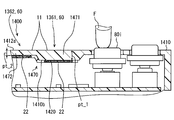
- the sensitivity reduction structure 670 in the sixth embodiment includes an operation panel 610 that changes the plate thickness of the switch region 612a at various places.
- a first region 671 and a second region 672 are provided in the operation panel 610 of the sixth embodiment.
- the first area 671 is a range in which the input surface 11 of the first touch switch 561 is formed.
- the second region 672 is a range in which the input surface 11 of the second touch switch 562 is formed.
- the plate thickness pt_1 of the first region 671 is thicker than the plate thickness pt_2 of the second region 672.
- each transparent electrode 22 is positioned on each back surface 10b of the first region 671 and the second region 672.
- the sensitivity of the first touch switch 561 is made lower than the sensitivity of the second touch switch 562 by the sensitivity reduction structure 670. Therefore, the same effect as the fifth embodiment is achieved, and erroneous detection of the contact operation in the first touch switch 561 is reduced. In addition, in the above-described configuration, since the area of each input surface 11 is maintained, the operability of each touch switch 60 is naturally ensured.
- the first touch switch 561 is more sensitive than the second touch switch 562 because the plate thickness pt_1 of the first region 671 is thicker than the plate thickness pt_2 of the second region 672. Is also low. As described above, the sensitivity of the first touch switch 561 can be lowered even with a simple structure in which the thickness of the operation panel 610 is changed. Therefore, by adopting the above-described configuration, it is possible to easily realize the operation device 600 that is difficult to erroneously detect the rotation operation on the dial knob 30 as a contact operation.
- the operation panel 610 corresponds to a “panel unit” of the present disclosure.
- the seventh embodiment of the present disclosure shown in FIGS. 21 and 22 is a modification of the sixth embodiment.
- the thickness of the operation panel 710 is substantially constant.
- the sensitivity lowering structure 770 provided in the operating device 700 includes a first switch electrode 722a and a second switch electrode 722b whose electrode areas are changed.
- the first switch electrode 722a and the second switch electrode 722b are formed in the film sensor 720.
- the first switch electrode 722 a is arranged on the back surface side of the input surface 11 of the first touch switch 561 so as to overlap the input surface 11.
- the first switch electrode 722a accumulates electric charge with the finger F (see FIG. 20) that has touched the input surface 11 of the first touch switch 561.
- the first switch electrode 722a is a reduced size of the second switch electrode 722b, and is formed in a rectangular shape having a longitudinal direction. Similar to the second switch electrode 722b, the outer edge of the first switch electrode 722a faces the wiring unit 23 connected to the capacitance measuring unit 54 (see FIG. 4) and is surrounded by the wiring unit 23 around the entire circumference. Yes.
- the electrode area of the first switch electrode 722a is smaller than the electrode area of the second switch electrode 722b.
- the second switch electrode 722 b is arranged on the back surface side of the input surface 11 of the second touch switch 562 so as to overlap the input surface 11.
- the second switch electrode 722b accumulates electric charge with the finger F (see FIG. 20) that has touched the input surface 11 of the second touch switch 562.
- the electrode area of the second switch electrode 722b is equivalent to the electrode area of the transparent electrode 22 (see FIG. 3) of the first embodiment.
- the area of the first switch electrode 722a is smaller than the area of the second switch electrode 722b. Therefore, even if a similar contact operation is performed on the touch switches 561 and 562, the electric charge accumulated between the first switch electrode 722a and the finger F (see FIG. 20) is between the second switch electrode 722b and the finger F. Less than the charge stored in the. As described above, the sensitivity of the first touch switch 561 is set lower than the sensitivity of the second touch switch 562.
- the first touch switch 561 is also used in the sensitivity reduction structure 770 including the first switch electrode 722a and the second switch electrode 722b in which the electrode area is changed, as in the sixth embodiment.
- the sensitivity is reduced. Therefore, the situation where the rotation operation to the dial knob 30 is erroneously detected by the first touch switch 561 as the contact operation is reduced.
- the sensitivity of the first touch switch 561 is reduced by a simple structure in which the electrode areas of the switch electrodes 722a and 722b are changed. Therefore, a configuration capable of avoiding erroneous detection associated with the rotation operation on the dial knob 30 becomes easier to implement.
- the operation panel 710 corresponds to a “panel unit” of the present disclosure.
- the eighth embodiment of the present disclosure shown in FIG. 23 is a modification of the seventh embodiment.
- the lengths of the long side and the short side of the first switch electrode 822a in the eighth embodiment are substantially the same as the lengths of the long side and the short side of the second switch electrode 722b (see FIG. 22).
- the first switch electrode 822a is formed in a comb shape. More specifically, the first switch electrode 822a has a plurality (two) of non-electrode regions 873 extending in a strip shape and spaced from each other. The non-electrode region 873 extends along the long side from the short side of the first switch electrode 822a adjacent to the dial knob 30 (see FIG. 21). By forming the non-electrode region 873, the electrode area of the first switch electrode 822a is made smaller than the electrode area of the second switch electrode 722b.
- the first touch switch 561 ( 21)
- the non-electrode region 873 is formed closer to the dial knob 30 (see FIG. 21)
- the gap between the first switch electrode 822a and the finger F (see FIG. 21) is near the dial knob 30. It is difficult to accumulate charges on the surface. Therefore, the sensitivity in the vicinity of the dial knob 30 in the first touch switch 561 can be partially reduced. Therefore, it is possible to accurately eliminate a situation in which the rotation operation is erroneously detected as the contact operation while maintaining high sensitivity to the contact operation.
- the ninth embodiment of the present disclosure illustrated in FIG. 24 is another modification example of the seventh embodiment.
- the first switch electrode 922a is formed in substantially the same shape as the second switch electrode 722b (see FIG. 22).
- the wiring part 923 connected to the capacitance measuring unit 54 is shorter than the wiring part 23 (see FIG. 3) corresponding to the first embodiment.
- the wiring portion 923 is connected to one of the two short sides that form the outer edge of the first switch electrode 922a and spaced from the dial knob 30 (see FIG. 21).
- the electric charge accumulated at a position far from the wiring portion 923 in the first switch electrode 922a is hardly detected by the capacitance measuring portion 54 (see FIG. 4). Therefore, the sensitivity in the vicinity of the dial knob 30 (see FIG. 21) in the first touch switch 561 (see FIG. 21) can be partially reduced. Therefore, even in the sensitivity reduction structure 970 including the film sensor 920, as in the eighth embodiment, the situation in which the rotation operation is erroneously detected as the contact operation is accurately excluded while maintaining high sensitivity to the contact operation. Can do.
- the operating device 1000 according to the tenth embodiment of the present disclosure shown in FIGS. 25 to 27 is still another modification of the first embodiment.
- the operating device 1000 according to the tenth embodiment is provided with a plurality of mechanical switches 80 instead of the dial knob 30 (see FIG. 1).
- a plurality of switch openings 1018 are formed together with the recesses 12, the protrusions 13, and the display openings 19 instead of the dial openings 18 (see FIG. 1).
- the switch opening 1018 is a rectangular through hole through which the mechanical switch 80 is inserted.
- Three switch openings 1018 are provided on both sides of the recess 12 in the horizontal direction of the operation panel 1010.
- Each mechanical switch 80 shown in FIGS. 25 and 26 is formed in a rectangular parallelepiped shape as a whole by a hard material such as resin. Each mechanical switch 80 is inserted into each switch opening 1018 in a posture in which the height direction is substantially orthogonal to the reference surface portion 1010a. The mechanical switch 80 protrudes in the front direction from the reference surface portion 1010 a at a position along with the touch switch 60.
- Each mechanical switch 80 is formed with a flange 83 and a pressing top surface 81.
- the flange 83 is in contact with the periphery of the switch opening 1018 from the back by a shape protruding from the side surface of the mechanical switch 80 to the outer peripheral side.
- the flange 83 is formed on the side surface of the mechanical switch 80 over the entire circumference.
- the pressing top surface 81 is a top surface of the mechanical switch 80 protruding from the switch opening 1018 toward the front surface.
- the pressing top surface 81 has a planar shape along the reference surface portion 1010a and contacts the operator's finger F.
- an icon 81 a that abstracts the function assigned to each mechanical switch 80 is formed on each pressing top surface 81.
- the mechanical switch 80 can be displaced in the back direction by a pressing operation input to the pressing top surface 81.
- the operation panel 1010 is provided with a middle step surface 1040 corresponding to the middle step surface 40 (see FIG. 2) of the first embodiment.
- the middle step surface 1040 is formed by the top surface 14 of the operation panel 1010, and is positioned between two of the plurality of mechanical switches 80 (hereinafter referred to as the inner switch 80 i) and the input surface 11. is doing.
- the middle step surface 1040 is located in front of the input surface 11 and extends in a planar shape around the mechanical switch 80 along the input surface 11.
- the control circuit 1050 shown in FIGS. 26 and 27 includes a plurality of press detection units 56 (see FIG. 27) in addition to the capacitance measurement unit 54, the operation determination unit 52, and the control unit 51 that are substantially the same as those in the first embodiment. Has only one).
- the press detection unit 56 is a tactile switch for detecting a pressing operation input to the mechanical switch 80.
- the pressure detection unit 56 is mounted in an area located in the back direction of the mechanical switch 80 on the mounting surface of the circuit board 59.
- the press detection part 56 makes the plunger part 56a which protruded in the front direction contact the mechanical switch 80.
- the press detection unit 56 presses the mechanical switch 80 in the front direction via the plunger unit 56a by the restoring force of an elastic member such as rubber provided inside.
- the pressing detecting unit 56 When the plunger portion 56a is displaced in the back direction together with the mechanical switch 80 by the pressing operation on the pressing top surface 81, the pressing detecting unit 56 is turned on. Signals indicating the ON state and the OFF state of the press detection unit 56 are acquired by the control unit 51.
- the middle step surface 1040 is formed, the area of each input surface 11 can be maintained, so that the operability of each touch switch 60 is not easily impaired. Therefore, after ensuring the operability of each touch switch 60, the operating device 1000 with reduced false detection is realized.
- the operation panel 1010 corresponds to the “panel portion” of the present disclosure
- the mechanical switch 80 corresponds to the “press switch portion” of the present disclosure.
- the eleventh embodiment of the present disclosure shown in FIGS. 28 and 29 is a modification of the third embodiment.
- the operating device 1100 according to the eleventh embodiment is provided with a plurality of mechanical switches 80 similar to those in the tenth embodiment, instead of the dial knob 30 (see FIG. 8).
- the operation panel 1110 of the eleventh embodiment is provided with two detection switches 1155.
- the detection switch 1155 has a configuration corresponding to the detection switch 355 (see FIG. 8) of the third embodiment, and is located between the mechanical switch 80 and the input surface 11.
- the detection switch 1155 detects the finger F touching the inner switch 80i.
- the detection switch 1155 includes an area where the middle surface 1140 is formed on the operation panel 1110, an extension area 1125 of the film sensor 1120, and the like.
- the middle step surface 1140 corresponds to the middle step surface 1040 (see FIG. 26) of the tenth embodiment, and is provided in a region closer to the recess 1112 than the inner switch 80i in the reference surface portion 1110a.
- the reference surface portion 1110 a is a planar region formed around the switch opening 1018 by the top surface 14 of the protruding portion 13.
- the extension region 1125 corresponds to the extension region (see FIG. 9) of the third embodiment, and generates a capacitance between the finger F that is in contact with or close to the middle surface 1140 by contact with the pressing top surface 81. .
- the operation determination unit 52 (see FIG. 27) of the eleventh embodiment described above performs an operation determination process substantially the same as the process shown in FIG. Therefore, when the detection switch 1155 detects the finger F, the operation determination unit 52 makes contact with the closest switch 61 even if the capacitance measured by the closest switch 61 exceeds the threshold Cth. Does not determine whether there is an operation. As a result, not only the contact of the finger F with the closest switch 61 is blocked by the middle step surface 1140, but also the determination of the presence of the contact operation with respect to the closest switch 61 is performed during the input of the pressing operation to the inner switch 80i. Disappear.
- the operation panel 1110 corresponds to a “panel unit” of the present disclosure.
- the twelfth embodiment of the present disclosure shown in FIGS. 30 and 31 is a modification of the eleventh embodiment.
- a recess 1112 (see FIG. 29) is omitted from the operation panel 1210 of the operation device 1200 according to the twelfth embodiment. Therefore, the switch region 1212a forming the input surface 11 is located on the same plane as the reference surface portion 1210a around the switch opening 1018.
- a detection switch 1255 substantially the same as the detection switch 1155 (see FIG. 29) of the eleventh embodiment is provided between the inner switch 80i and the input surface 11.
- the detection switch 1255 includes a detection area 1211 of the operation panel 1210, an extension area 1225 of the film sensor 1220, and the like.
- the detection area 1211 is located on both sides in the horizontal direction of the switch area 1212a in the reference surface portion 1210a, and is sandwiched between the switch area 1212a and the switch opening 1018.
- the detection region 1211 has a shape extending in a strip shape in the vertical direction in which the two inner switches 80i are arranged.
- the extension region 1225 is a portion located on the back side of the detection region 1211 in the film sensor 1220.
- the operation determination unit 52 (FIG. 27). (See) does not determine whether there is a touch operation on the closest switch 61. Therefore, during the input of the pressing operation to the inner switch 80i, the presence / absence of the contact operation on the closest switch 61 is not performed. Therefore, it is possible to avoid a situation in which a change in capacitance caused by the finger F that inputs a pressing operation is erroneously detected as a contact operation to the closest switch 61.
- the detection switch 1255 is provided between the input surface 11 and the inner switch 80i, the area of the switch region 1212a can be secured. Therefore, the operability of each touch switch 60 is ensured.
- the operation panel 1210 corresponds to a “panel unit” of the present disclosure.
- the thirteenth embodiment of the present disclosure shown in FIG. 32 is a modification of the fifth embodiment.
- the operating device 1300 according to the thirteenth embodiment is provided with a plurality of mechanical switches 80 similar to those of the tenth embodiment, instead of the dial knob 30 (see FIG. 13).
- the input surfaces 11 of the plurality of touch switches 60 are formed between the three mechanical switch groups arranged three by three.
- two of the plurality of touch switches 60 that are closest to the inner switch 80i are the first touch switches 1361, and the six that are sandwiched between the first touch switches 1361 are the second touches.
- the switch 1362 is used.
- the first touch switch 1361 is assigned only a simple switching function that is less likely to be repeatedly hit.
- the second touch switch 1362 includes a switch to which an adjustment function and a circulation switching function that are assumed to be repeatedly hit are assigned.
- the sensitivity of the first touch switch 1361 is set lower than the sensitivity of the second touch switch 1362 as in the fifth embodiment.
- the capacitance value is set higher than Cth2.
- the first delay time t_r1 is set longer than the second delay time t_r2 set to a value close to zero.
- the first delay time t_r1 is a time from when the capacitance value detected by the first touch switch 1361 exceeds the first threshold value Cth1 until the contact operation is determined. (See FIG. 15).
- the second delay time t_r2 is a period from when the capacitance value detected by the second touch switch 1362 exceeds the second threshold value Cth2 until the contact operation is determined. Time (see FIG. 15).
- the operation determination unit 52 indicates that the detected capacitance value is stabilized only for the first touch switch 1361 among the first touch switch 1361 and the second touch switch 1362. Based on the above, the presence / absence of contact operation is determined (see FIG. 16). The operation determination unit 52 determines that the capacitance has stabilized based on the fact that the capacitance value has changed for a predetermined time t_s or more within a predetermined fluctuation range (see FIG. 18). Based on this determination, the operation determination unit 52 determines whether there is a touch operation on the first touch switch 1361.
- the operation determination unit 52 detects the pressing operation to the inner switch 80i and the contact operation to the first touch switch 1361 adjacent to the inner switch 80i at the same timing, the inner switch 80i. Give priority to the pressing operation. More specifically, the operation determination unit 52 determines whether or not the first touch switch 1361 has a contact operation, and then from a predetermined time t_rm (see FIG. 15) and each press detection unit 56 (see FIG. 27). Based on the signal to be acquired, the presence or absence of a pressing operation is monitored. If a pressing operation is detected by the pressing detection unit 56 close to the first touch switch 1361 within the monitoring time t_rm, the determination of the presence of the previous contact operation is cancelled.
- the operation panel 1310 corresponds to the “panel unit” of the present disclosure
- the press detection unit 56 corresponds to the “press detection unit” of the present disclosure.
- the fourteenth embodiment of the present disclosure shown in FIG. 33 is a modification of the thirteenth embodiment.
- the operating device 1400 according to the fourteenth embodiment is provided with a sensitivity lowering structure 1470 that makes the sensitivity of the first touch switch 1361 lower than the sensitivity of the second touch switch 1362.
- the sensitivity lowering structure 1470 includes an operation panel 1410 that changes the plate thickness of the switch region 1412a at various places.
- the operation panel 1410 is provided with a first area 1471 and a second area 1472.
- the first region 1471 is a range in which the input surface 11 of the first touch switch 1361 is formed.
- the second region 1472 is a range in which the input surface 11 of the second touch switch 1362 is formed. Similar to the first region 671 (see FIG.
- the plate thickness pt_1 of the first region 1471 is made thicker than the plate thickness pt_2 of the second region 1472. ing. Due to the difference between the plate thicknesses pt_1 and pt_2, a step is formed on the back surface 1410b of the operation panel 1410.
- the transparent electrode 22 is positioned on each of the back surfaces 1410b of the first region 1471 and the second region 1472 in a state where the film sensor 1420 is bent in accordance with the level difference of the back surface 1410b.
- the sensitivity of the first touch switch 1361 is made lower than the sensitivity of the second touch switch 1362 by the sensitivity reduction structure 1470. Therefore, the same effect as that of the twelfth embodiment is achieved, and a situation in which the finger F that inputs a pressing operation to the inner switch 80i is erroneously detected as a contact operation by the first touch switch 1361 is less likely to occur. In addition, by maintaining the area of each input surface 11, the operability of each touch switch 60 is naturally secured.
- the operation panel 1410 corresponds to a “panel unit” of the present disclosure.
- the fifteenth embodiment of the present disclosure shown in FIG. 34 is a modification of the seventh embodiment.
- the dial knob 30 and the operation panel 710 (see FIG. 21) of the operation device 700 are substantially the same as the mechanical switches 80 and the thirteenth embodiment similar to the tenth embodiment.
- the operation panel 1510 is replaced.
- the sensitivity lowering structure 1570 of the operating device 1500 is substantially the same as the sensitivity lowering structure 770 (see FIG. 21) of the seventh embodiment, and the first switch electrode 722a and the first switch electrodes 722a having different electrode areas as shown in FIG. A second switch electrode 722b is included.
- the first switch electrode 722a is disposed on the back surface side of the input surface 11 of the first touch switch 1361 shown in FIG.
- the first switch electrode 722 a is disposed on the back surface side of the input surface 11 of the second touch switch 1362 so as to overlap the input surface 11.
- the area of the first switch electrode 722a is smaller than the area of the second switch electrode 722b. Therefore, even if a similar contact operation is performed on each of the touch switches 1361 and 1362, the charge accumulated between the first switch electrode 722a and the finger F (see FIG. 31) is between the second switch electrode 722b and the finger F. Less than the charge stored in the. As a result, the sensitivity of the first touch switch 1361 is lower than the sensitivity of the second touch switch 1362. Therefore, a situation in which a pressing operation on the inner switch 80i is erroneously detected by the first touch switch 1361 as a contact operation is reduced.
- the operation panel 1510 corresponds to a “panel unit” of the present disclosure.
- a sensitivity lowering structure including is adopted. Due to the form in which the non-electrode region 873 extends from one short side close to the inner switch 80i (see FIG. 34), the electrode area of the first switch electrode 822a is larger than the electrode area of the second switch electrode 722b shown in FIG. It has been made smaller. As a result, the sensitivity of the first touch switch 1361 is lower than the sensitivity of the second touch switch 1362.
- the sensitivity reduction includes the film sensor 920 in which the second switch electrode 722b and the first switch electrode 922a illustrated in FIG. 24 are combined instead of the sensitivity reduction structure 1570 of the fifteenth embodiment. Structure is adopted.
- the wiring part 923 of the film sensor 920 is connected to only one of the two short sides of the first switch electrode 922a that is located away from the inner switch 80i (see FIG. 34). With such a configuration, the electric charge accumulated at a position far from the wiring part 923 in the first switch electrode 922a is hardly detected by the capacitance measuring part 54 (see FIG. 27). As a result, the sensitivity particularly in the vicinity of the inner switch 80i in the first touch switch 1361 shown in FIG. 34 may be partially reduced.
- the position of the input surface 11 is kept away from the dial side surface 31 by the concave portion 12 recessed from the reference surface portion 10a (see FIG. 2).
- the protrusion that forms the middle step surface from the top surface is formed on the operation panel. It can be formed.
- the position of the input surface can be kept away from the dial side surface.
- the detection switch 355 in the third embodiment is formed as a configuration including the middle step surface 340 formed on the operation panel 310.
- the detection switch can be formed in the dial knob as a configuration including the middle step surface 240 (enlarged surface 233) of the dial knob 230 of the second embodiment, for example.
- the detection switch can be formed on both the operation panel and the dial knob.
- dial knobs are provided at both ends in the horizontal direction of the operation panel.
- the position and number of such dial knobs can be changed as appropriate.
- only one dial knob may be provided at the center of the operation panel.
- three or more dial knobs may be provided.
- the shape of the dial knob is not limited to the cylindrical shape and the two-stage cylindrical shape described above.
- the shape of the dial knob can be appropriately changed to, for example, a polygonal column shape, a spherical shape, a hemispherical shape, and a conical shape. Therefore, the shape of the dial side surface is not limited to the cylindrical surface shape.
- three mechanical switches are provided at each of the horizontal ends of the operation panel.
- the position, number, shape, and type of such mechanical switches can be changed as appropriate.
- a toggle switch, a seesaw switch, a slide switch, or the like can be used as the mechanical switch.
- the direction in which the mechanical switch is pressed is not limited to the back direction as in the above embodiment.
- the mechanical switch may be configured to be pressed in the vertical direction or the horizontal direction along the outer surface of the operation panel.
- the dial knob and the mechanical switch may be provided together in one operating device.
- the determination that the contact operation is performed can be canceled by updating the determination that the contact operation has been made once by the determination that there is no contact operation (FIG. 19). reference).
- the processing method implemented in the control circuit can be appropriately changed as long as priority can be given to the rotation operation or the pressing operation among the contact operation and the rotation operation or the pressing operation detected at the same timing.
- the control unit that acquires information indicating that there is a rotation operation from the rotation detection unit does not acquire the determination of the presence of the contact operation from the operation determination unit, or does not control the air conditioner corresponding to the determination. May be.
- control unit that acquires information indicating that there is a pressing operation from the pressing detection unit does not acquire the determination that there is a contact operation from the operation determination unit, or does not perform control of the air conditioner corresponding to the determination. It may be made like.
- the priority of the rotation operation or the pressing operation is also realized by the processing by the control unit described above. Thus, it is possible to cancel the presence determination of the contact operation not by the process by the operation determination unit but by the process by the control unit.
- different threshold values Cth1 and Cth2 are set for the first touch switch and the second touch switch, respectively.
- the threshold values of the first touch switch and the second touch switch may be the same value.
- different threshold values can be set for the individual first touch switches.
- different threshold values can be set for a plurality of second touch switches.
- the operation determination unit determines that the capacitance has stabilized based on the fact that the capacitance value has changed within a predetermined fluctuation range for a predetermined time or more.
- the processing method for determining that the capacitance has been stabilized is not limited to the above. A well-known method for detecting the stabilization of the capacitance can be appropriately employed.
- the input surface of the touch switch is formed by the operation panel.
- a display screen of a touch panel display may form the input surface of the touch switch.
- the switches 562a to 562c to which the circulation switching function and the adjustment function are assigned are exemplified, but the other second touch switches naturally have a simple switching function. Can be assigned.
- a circulation switching function and an adjustment function can be assigned to the first touch switch.
- the sensitivity reduction of the first touch switch may be realized only by adjusting each threshold value.
- the sensitivity reduction of the first touch switch may be realized by combining the adjustment of each threshold value and the adjustment of each delay time.
- the sensitivity reduction of a 1st touch switch may be implement
- the sensitivity reduction structures of the sixth and fourteenth embodiments and the sensitivity reduction structures of the seventh and fifteenth embodiments can be combined with each other. That is, the sensitivity lowering structure may be a combination of a configuration for changing the thickness of the operation panel and a configuration for changing the area of the transparent electrode.
- control unit 51 the capacitance measurement unit 54, and the operation determination unit 52 of the control circuits 50 and 1050 may be realized by a dedicated integrated circuit, or a predetermined program It may be a functional block of a processor that executes Alternatively, it may be provided by hardware and software different from those described above, or a combination thereof.
- the present disclosure is not limited to such an operation device for an air conditioner, but can be applied to an operation device for operating another device mounted on the vehicle.
- the present disclosure is applicable to all devices.
- an operating device provided with a touch switch that detects a change in electrostatic capacitance accompanying a contact operation performed by an operating body.
- the operation device has a panel portion that forms an input surface in contact with the operation body among the touch switches, and protrudes from the panel portion in the front direction facing the input surface at a position aligned with the touch switch, so that the rotation operation by the operation body can be performed.
- a dial portion that is input to the cylindrical side surface. Between the input surface and the cylindrical side surface, there is provided a middle step surface that is positioned in front of the input surface and extends to the outer peripheral side of the cylindrical side surface.
- an operator who touches the operating body on the cylindrical side surface of the dial portion inputs the operating body to the far side in order to input a rotation operation to the cylindrical side surface of the dial unit. Even when it is moved, the movement of the operating body to the back side is hindered by the middle step surface extending to the outer peripheral side of the cylindrical side surface. In this way, if the operating body hits the middle stage surface located in the front direction of the input surface between the input surface and the cylindrical side surface, the area of the input surface is maintained so as not to impair the operability of the touch switch. Even if this is maintained, the distance from the operating body touching the cylindrical side surface to the input surface can be secured. Therefore, even if an operating body close to the input surface causes a change in capacitance due to a rotation operation to the dial unit, such a change in capacitance is erroneously detected as a touch switch operation. The situation is avoided.
- an operating device provided with a touch switch that detects a change in capacitance accompanying a contact operation performed by an operating body.
- the operation device has a panel portion that forms an input surface in contact with the operating body among the touch switches, and protrudes from the panel portion in the front direction facing the input surface at a position aligned with the touch switch, and is rotated by the operating body.
- an operation determination unit that determines whether there is a touch operation on the touch switch based on a change in capacitance detected by the touch switch, an input surface and the cylindrical shape
- a detection switch that detects an operating body that is located between the side surface and touches the cylindrical side surface. The operation determination unit does not determine whether there is a touch operation on the touch switch when the detection switch detects the operating body.
- the operation body touching the cylindrical side surface is detected by the detection switch during the input of the rotation operation to the dial unit. I will not. Therefore, even if an operating body close to the input surface causes a change in capacitance due to a rotation operation to the dial unit, such a change in capacitance is erroneously detected as a touch switch operation. The situation is avoided. In addition, even if a detection switch is provided between the input surface and the cylindrical side surface, the area of the input surface can be maintained. Therefore, the operability of the touch switch is ensured.
- an operating device provided with a plurality of touch switches (60) for detecting a change in capacitance accompanying a contact operation performed by the operating body (F).
- the operation device protrudes from the panel unit in the front direction facing the input surface at the position where the input unit comes in contact with the operation body among the touch switches and the plurality of touch switches, and is rotated by the operation body.
- a dial unit that inputs an operation to the cylindrical side surface, and an operation determination unit that determines whether or not there is a touch operation on the touch switch based on a change in capacitance detected by each touch switch.
- the operation determination unit makes the sensitivity of the first touch switch closest to the dial unit among the plurality of touch switches lower than the sensitivity of the second touch switch separated from the dial unit than the first touch switch. .
- an operating device provided with a plurality of touch switches that detect a change in capacitance accompanying a contact operation performed by an operating body.
- the panel part that forms the input surface that comes into contact with the operating body, and at the position along with the multiple touch switches, it projects beyond the panel part in the front direction facing the input surface, and the rotating operation by the operating body is cylindrical A dial portion that is input to the side surface.
- the sensitivity of the first touch switch closest to the dial portion among the plurality of touch switches is lower than the sensitivity of the second touch switch (562) farther from the dial portion than the first touch switch.
- Sensitivity reduction structures (670, 770, 870, 970) are provided.
- the sensitivity of the first touch switch closest to the dial unit is controlled by the operation determination unit or the sensitivity lowering structure of the second touch switch farther from the dial unit than the first touch switch. It is lower than the sensitivity. Therefore, even if the operating body close to the input surface causes a change in capacitance due to the rotation operation to the dial part, such a change in capacitance is erroneously detected as a contact operation to the first touch switch. This situation is avoided.
- the area of the input surface can be maintained if the sensitivity of the first touch switch is lowered by the control by the operation determination unit or the sensitivity reduction structure. Therefore, the operability of the touch switch is ensured.
- an operating device provided with a touch switch that detects a change in capacitance accompanying a contact operation performed by an operating body.
- the operating device protrudes from the panel portion in the front direction facing the input surface at a position aligned with the touch switch and the panel portion that forms the input surface in contact with the operating body among the touch switches.
- An input pressure switch unit is provided between the input surface and the press switch part. Between the input surface and the press switch part, a middle step surface located in the front direction from the input surface is provided.
- the operation device of the present disclosure even when an operator who has touched the operating body with the pressing switch unit moves the operating body to the back side in order to input a pressing operation to the pressing switch unit, The movement to the back side of the body is hindered by the middle step surface located between the press switch part and the input surface. In this way, if the operating body hits the middle surface located in front of the input surface, the touch switch can be touched even if the area of the input surface is maintained so as not to impair the operability of the touch switch. The distance from the operating body to the input surface can be ensured. Therefore, even if an operating body close to the input surface causes a change in capacitance due to a pressing operation on the pressing switch unit, such a change in capacitance is erroneously detected as a touch switch touch operation. This situation is avoided.
- an operating device provided with a touch switch that detects a change in capacitance accompanying a contact operation performed by an operating body.
- the operating device protrudes from the panel portion in the front direction facing the input surface at a position aligned with the touch switch at a position aligned with the touch switch, and a pressing operation by the operating body.
- the operation determination unit that determines whether there is a contact operation to the touch switch based on the change in capacitance detected by the touch switch, And a detection switch that detects an operating body that is located between and touching the pressing switch unit.
- the operation determining unit does not determine whether there is a touch operation on the touch switch when the detection switch detects the operating body.
- the operating device of the present disclosure during the input of the pressing operation to the pressing switch unit, since the operating body touching the pressing switch unit is detected by the detection switch, it is determined that there is a touch operation on the touch switch. I will not. Therefore, even if an operating body close to the input surface causes a change in capacitance due to a pressing operation on the pressing switch unit, such a change in capacitance is erroneously detected as a touch switch touch operation. This situation is avoided. In addition, even if a detection switch is provided between the input surface and the pressing switch unit, the area of the input surface can be maintained. Therefore, the operability of the touch switch is ensured.
- an operating device provided with a plurality of touch switches that detect a change in capacitance accompanying a contact operation performed by an operating body.
- the operation device protrudes from the panel unit in the front direction facing the input surface at a position aligned with the touch panel and a panel unit that forms an input surface in contact with the operation body among the touch switches, and is pressed by the operation body.
- the operation determination unit makes the sensitivity of the first touch switch closest to the pressing switch unit among the plurality of touch switches lower than the sensitivity of the second touch switch separated from the pressing switch unit than the first touch switch. .
- an operating device provided with a plurality of touch switches that detect a change in capacitance accompanying a contact operation performed by an operating body.
- the operation device protrudes from the panel unit in the front direction facing the input surface at a position aligned with the touch panel and a panel unit that forms an input surface in contact with the operation body among the touch switches, and is pressed by the operation body.
- a press switch unit to which an operation is input.
- a sensitivity lowering structure that lowers the sensitivity of the first touch switch closest to the pressing switch portion among the plurality of touch switches to be lower than the sensitivity of the second touch switch separated from the pressing switch portion than the first touch switch, Provided.
- the sensitivity of the first touch switch closest to the pressing switch unit is more separated from the pressing switch unit than the first touch switch by the control by the operation determination unit or the sensitivity reduction structure.
- the sensitivity of the switch is lower. Therefore, even if an operating body that is close to the input surface causes a change in capacitance due to a pressing operation on the pressing switch unit, such a change in capacitance is erroneously detected as a touch operation on the first touch switch. The situation that is done is avoided.
- the area of the input surface can be easily maintained if the sensitivity of the first touch switch is lowered by the control by the operation determination unit or the sensitivity reduction structure. Therefore, the operability of the touch switch is ensured.
Landscapes
- Engineering & Computer Science (AREA)
- General Engineering & Computer Science (AREA)
- Theoretical Computer Science (AREA)
- Human Computer Interaction (AREA)
- Physics & Mathematics (AREA)
- General Physics & Mathematics (AREA)
- Chemical & Material Sciences (AREA)
- Combustion & Propulsion (AREA)
- Transportation (AREA)
- Mechanical Engineering (AREA)
- Switches That Are Operated By Magnetic Or Electric Fields (AREA)
- Rotary Switch, Piano Key Switch, And Lever Switch (AREA)
- Position Input By Displaying (AREA)
- Switch Cases, Indication, And Locking (AREA)
Abstract
一実施形態の操作装置(100)は、操作パネル(10)及びダイヤルノブ(30)を備える。操作パネル(10)は、タッチスイッチ(60)のうちで手指(F)と接触する入力面(11)を構成する。ダイヤルノブ(30)は、タッチスイッチ(60)と並ぶ位置にて、入力面(11)の向く前面方向に操作パネル(10)よりも突出する。ダイヤルノブ(30)のダイヤル側面(31)には、回転操作が入力される。入力面(11)とダイヤル側面(31)との間には、中段面(40)が設けられている。中段面(40)は、入力面(11)よりも前面方向に位置し、且つ、ダイヤル側面(31)の外周側に拡がる形状により、手指(F)の奥側への移動を規制する。
Description
本出願は、2013年11月21日に出願された日本国特許出願2013-241244号、2014年7月3日に出願された日本国特許出願2014-137873号に基づくものであり、ここにその記載内容を参照により援用する。
本開示は、タッチスイッチが設けられた操作装置に関する。
従来、例えば特許文献1に開示の車載機器の操作装置には、手指等との間に生じる静電容量の変化を検出するタッチスイッチが設けられている。こうした操作装置では、操作者に向けて露出したパネル部がタッチスイッチの入力面を形成している。操作者は、手指を入力面に触れさせる接触操作により、タッチスイッチへの入力を行う。
本願発明者は、タッチスイッチに加えて、回転操作の入力されるダイヤル部及び押圧操作の入力される押圧スイッチ部を備えた操作装置について開発を行っていた。開発過程において、本願発明者は、タッチスイッチとダイヤル部又は押圧スイッチ部とが並ぶ構成では、ダイヤル部への回転操作又は押圧スイッチ部への押圧操作を、タッチスイッチへの接触操作として誤検知し易いことを見出した。
回転操作を入力する状況を例に詳しく説明すると、ダイヤル部は、入力面の向く前面方向にパネル部よりも突出している。そして、ダイヤル部への回転操作は、ダイヤル部に形成された筒状の側面に入力される。故に、操作者は、ダイヤル部の筒状側面を確実に把持しようとして、筒状側面の奥側へと手指を移動させ易い。こうして、手指を筒状側面の奥側へと移動させた場合に、入力面と筒状側面に触れている手指との間の距離は、確保困難となってしまうおそれがある。そのため、ダイヤル部への回転操作に伴って入力面に近接した操作体が静電容量の変化を生じさせ、この静電容量の変化がタッチスイッチへの接触操作として誤って検知されてしまうおそれがある。誤検知を回避するために、入力面を狭めてダイヤル部から遠ざけることも考えられるが、入力面の小型化は、タッチスイッチの操作性を悪化させるため望ましくない。
本開示は、以上説明した問題に鑑みてなされたものであって、その目的は、タッチスイッチの操作性を損なうことなく、ダイヤル部又は押圧スイッチ部への各操作がタッチスイッチへの接触操作として誤検知されることを回避可能な操作装置を提供することにある。
本開示の一態様によれば、操作体によって行われる接触操作に伴った静電容量の変化を検出するタッチスイッチが設けられる操作装置が提供される。操作装置は、タッチスイッチのうちで操作体と接触する入力面を形成するパネル部と、タッチスイッチと並ぶ位置にて、入力面の向く前面方向にパネル部よりも突出し、操作体による回転操作が筒状側面に入力されるダイヤル部と、を備える。入力面と筒状側面との間には、入力面よりも前面方向に位置し筒状側面の外周側に拡がる中段面が設けられる。
本開示の一態様に係る操作装置によれば、ダイヤル部の筒状側面に回転操作を入力すべく、当該筒状側面に操作体を触れさせた操作者が、より奥側へと操作体を移動させた場合でも、操作体の奥側への移動は、筒状側面の外周側に拡がる中段面によって阻まれる。このように、入力面と筒状側面との間にて当該入力面よりも前面方向に位置する中段面に操作体が突き当たるようにすれば、タッチスイッチの操作性を損なわないよう入力面の面積を維持しても、筒状側面に触れている操作体から入力面までの距離は、確保され得る。故に、ダイヤル部への回転操作に伴って入力面に近接した操作体が静電容量の変化を生じさせたとしても、こうした静電容量の変化がタッチスイッチへの接触操作として誤って検知される事態は、回避される。
さらに、本開示の他の態様によれば、操作体によって行われる接触操作に伴った静電容量の変化を検出するタッチスイッチが設けられる操作装置が提供される。操作装置は、タッチスイッチのうちで操作体と接触する入力面、を形成するパネル部と、タッチスイッチと並ぶ位置にて、入力面の向く前面方向にパネル部よりも突出し、操作体による回転操作が筒状側面に入力されるダイヤル部と、タッチスイッチにて検出される静電容量の変化に基づいて、当該タッチスイッチへの接触操作の有り判定を行う操作判定部と、入力面と筒状側面との間に位置し、筒状側面に触れている操作体を検知する検知スイッチと、を備える。操作判定部は、検知スイッチが操作体を検知している場合には、タッチスイッチに対する接触操作の有り判定しない。
他の態様に係る操作装置によれば、ダイヤル部への回転操作の入力中では、筒状側面に触れている操作体が検知スイッチによって検知されるため、タッチスイッチに対する接触操作の有り判定が行われない。故に、ダイヤル部への回転操作に伴って入力面に近接した操作体が静電容量の変化を生じさせたとしても、こうした静電容量の変化がタッチスイッチへの接触操作として誤って検知される事態は、回避される。加えて、入力面と筒状側面との間に検知スイッチを設けたとしても、入力面の面積は維持され得る。故に、タッチスイッチの操作性は確保される。
さらに、本開示の他の態様によれば、操作体(F)によって行われる接触操作に伴った静電容量の変化を検出するタッチスイッチ(60)が複数設けられる操作装置が提供される。操作装置は、タッチスイッチのうちで操作体と接触する入力面を形成するパネル部と、複数のタッチスイッチと並ぶ位置にて、入力面の向く前面方向にパネル部よりも突出し、操作体による回転操作が筒状側面に入力されるダイヤル部と、各タッチスイッチにて検出される静電容量の変化に基づいて、当該タッチスイッチへの接触操作の有り判定を行う操作判定部と、を備える。操作判定部は、複数のタッチスイッチのうちでダイヤル部に最も近接した第一タッチスイッチの感度を、当該第一タッチスイッチよりもダイヤル部から離間した第二タッチスイッチの感度よりも低くしている。
さらに、本開示の他の態様によれば、操作体によって行われる接触操作に伴った静電容量の変化を検出するタッチスイッチが複数設けられる操作装置が提供される。タッチスイッチのうちで操作体と接触する入力面を形成するパネル部と、複数のタッチスイッチと並ぶ位置にて、入力面の向く前面方向にパネル部よりも突出し、操作体による回転操作が筒状側面に入力されるダイヤル部と、を備える。操作装置には、複数のタッチスイッチのうちでダイヤル部に最も近接した第一タッチスイッチの感度を、当該第一タッチスイッチよりもダイヤル部から離間した第二タッチスイッチ(562)の感度よりも低くする感度低下構造(670,770,870,970)、が設けられる。
本開示の操作装置によれば、操作判定部による制御又は感度低下構造により、ダイヤル部に最も近接した第一タッチスイッチの感度が、第一タッチスイッチよりもダイヤル部から離間した第二タッチスイッチの感度よりも低くされている。故に、ダイヤル部への回転操作に伴って入力面に近接した操作体が静電容量の変化を引き起こしたとしても、こうした静電容量の変化が第一タッチスイッチへの接触操作として誤って検知される事態は、回避される。加えて、操作判定部による制御又は感度低下構造によって第一タッチスイッチの感度を低くする形態であれば、入力面の面積は維持され得る。故に、タッチスイッチの操作性は確保される。
さらに、本開示の他の態様によれば、操作体によって行われる接触操作に伴った静電容量の変化を検出するタッチスイッチが設けられる操作装置が提供される。操作装置は、タッチスイッチのうちで操作体と接触する入力面を形成するパネル部と、タッチスイッチと並ぶ位置にて、入力面の向く前面方向にパネル部よりも突出し、操作体による押圧操作が入力される押圧スイッチ部と、を備える。入力面と押圧スイッチ部との間には、入力面よりも前面方向に位置する中段面が設けられる。
本開示の操作装置によれば、押圧スイッチ部に押圧操作を入力すべく、当該押圧スイッチ部に操作体を触れさせた操作者が、より奥側へと操作体を移動させた場合でも、操作体の奥側への移動は、押圧スイッチ部と入力面との間に位置する中段面によって阻まれる。このように、入力面よりも前面方向に位置する中段面に操作体が突き当たるようにすれば、タッチスイッチの操作性を損なわないよう入力面の面積を維持しても、押圧スイッチ部に触れている操作体から入力面までの距離は、確保され得る。故に、押圧スイッチ部への押圧操作に伴って入力面に近接した操作体が静電容量の変化を生じさせたとしても、こうした静電容量の変化がタッチスイッチへの接触操作として誤って検知される事態は、回避される。
さらに、本開示の他の態様によれば、操作体によって行われる接触操作に伴った静電容量の変化を検出するタッチスイッチが設けられる操作装置が提供される。操作装置は、タッチスイッチのうちで操作体と接触する入力面、を形成するパネル部と、タッチスイッチと並ぶ位置にて、入力面の向く前面方向にパネル部よりも突出し、操作体による押圧操作が入力される押圧スイッチ部と、タッチスイッチにて検出される静電容量の変化に基づいて、当該タッチスイッチへの接触操作の有り判定を行う操作判定部と、入力面と押圧スイッチ部との間に位置し、押圧スイッチ部に触れている操作体を検知する検知スイッチと、を備える。操作判定部は、検知スイッチが操作体を検知している場合には、タッチスイッチに対する接触操作の有り判定を行わない。
本開示の操作装置によれば、押圧スイッチ部への押圧操作の入力中では、当該押圧スイッチ部に触れている操作体が検知スイッチによって検知されるため、タッチスイッチに対する接触操作の有り判定が行われない。故に、押圧スイッチ部への押圧操作に伴って入力面に近接した操作体が静電容量の変化を生じさせたとしても、こうした静電容量の変化がタッチスイッチへの接触操作として誤って検知される事態は、回避される。加えて、入力面と押圧スイッチ部との間に検知スイッチを設けたとしても、入力面の面積は維持され得る。故に、タッチスイッチの操作性は確保される。
さらに、本開示の他の態様によれば、操作体によって行われる接触操作に伴った静電容量の変化を検出するタッチスイッチが複数設けられる操作装置が提供される。操作装置は、タッチスイッチのうちで操作体と接触する入力面を形成するパネル部と、複数のタッチスイッチと並ぶ位置にて、入力面の向く前面方向にパネル部よりも突出し、操作体による押圧操作が入力される押圧スイッチ部と、各タッチスイッチにて検出される静電容量の変化に基づいて、当該タッチスイッチへの接触操作の有り判定を行う操作判定部と、を備える。操作判定部は、複数のタッチスイッチのうちで押圧スイッチ部に最も近接した第一タッチスイッチの感度を、当該第一タッチスイッチよりも押圧スイッチ部から離間した第二タッチスイッチの感度よりも低くする。
さらに、本開示の他の態様によれば、操作体によって行われる接触操作に伴った静電容量の変化を検出するタッチスイッチが複数設けられる操作装置が提供される。操作装置は、タッチスイッチのうちで操作体と接触する入力面を形成するパネル部と、複数のタッチスイッチと並ぶ位置にて、入力面の向く前面方向にパネル部よりも突出し、操作体による押圧操作が入力される押圧スイッチ部と、を備える。複数のタッチスイッチのうちで押圧スイッチ部に最も近接した第一タッチスイッチの感度を、当該第一タッチスイッチよりも押圧スイッチ部から離間した第二タッチスイッチの感度よりも低くする感度低下構造、が設けられる。
本開示の操作装置によれば、操作判定部による制御又は感度低下構造により、押圧スイッチ部に最も近接した第一タッチスイッチの感度が、第一タッチスイッチよりも押圧スイッチ部から離間した第二タッチスイッチの感度よりも低くされている。故に、押圧スイッチ部への押圧操作に伴って入力面に近接した操作体が静電容量の変化を引き起こしたとしても、こうした静電容量の変化が第一タッチスイッチへの接触操作として誤って検知される事態は、回避される。加えて、操作判定部による制御又は感度低下構造によって第一タッチスイッチの感度を低くする形態であれば、入力面の面積は容易に維持され得る。故に、タッチスイッチの操作性は確保される。
本開示の操作装置によれば、タッチスイッチの操作性を損なうことなく、ダイヤル部又は押圧スイッチ部への各操作がタッチスイッチへの接触操作として誤検知されることが回避される。
本開示についての上記および他の目的、特徴や利点は、添付の図面を参照した下記の詳細な説明から、より明確になる。添付図面において、
図1は、本開示の第一実施形態による操作装置の正面図である。り、
図2は、ダイヤルノブ周囲の構造を示す図であって、図1のII-II線断面図である。り、
図3は、フィルムセンサに設けられた透明電極及び配線部の形状を模式的に示す図であり、
図4は、操作装置の電気的な構成を示すブロック図であり、
図5は、凹部の形成により、最近接スイッチにて検出される静電容量の値が低下する原理を説明するための図であり、
図6は、本開示の第二実施形態による操作装置の正面図であり、
図7は、図6のVII-VII線断面図であり、
図8は、本開示の第三実施形態による操作装置の正面図であり、
図9は、図8のIX-IX線断面図であり、
図10は、操作判定部によって実施される操作判定処理を示すフローチャートであり、
図11は、本開示の第四実施形態による操作装置の正面図であり、
図12は、図11のXII-XII線断面図であり、
図13は、本開示の第五実施形態による操作装置の正面図であり、
図14は、操作判定部に設定された第一閾値及び第二閾値を比較して示す図であり、
図15は、操作判定部に設定された各遅れ時間及び監視時間を説明するためのタイミングチャートであり、
図16は、操作者による接触操作によって引き起こされる静電容量の変化を、操作開始からの経過時間に沿って示す図であり、
図17は、図16の領域XVIIを拡大して示す図であり、
図18は、図16の領域XVIIIを拡大して示す図であり、
図19は、操作判定部によって実施される操作判定処理を示すフローチャートであり、
図20は、第六実施形態による操作装置のダイヤルノブ周囲の構造を示す図であり、
図21は、本開示の第七実施形態による操作装置の正面図であり、
図22は、第七実施形態によるフィルムセンサに設けられた透明電極及び配線部の形状を模式的に示す図であり、
図23は、第八実施形態によるフィルムセンサに設けられた透明電極及び配線部の形状を模式的に示す図であり、
図24は、第九実施形態によるフィルムセンサに設けられた透明電極及び配線部の形状を模式的に示す図であり、
図25は、本開示の第十実施形態による操作装置の正面図であり、
図26は、メカニカルスイッチ周囲の構造を示す図であって、図25のXXVI-XXVI線断面図であり、
図27は、操作装置の電気的な構成を示すブロック図であり、
図28は、本開示の第十一実施形態による操作装置の正面図であり、
図29は、図28のXXIX-XXIX線断面図であり、
図30は、本開示の第十二実施形態による操作装置の正面図であり、
図31は、図30のXXXI-XXXI線断面図であり、
図32は、本開示の第十三実施形態による操作装置の正面図であり、
図33は、本開示の第十四実施形態による操作装置のメカニカルスイッチ周囲の構造を示す図であり、
図34は、本開示の第十五実施形態による操作装置の正面図である。
以下、本開示の複数の実施形態を図面に基づいて説明する。尚、各実施形態において対応する構成要素には同一の符号を付すことにより、重複する説明を省略する場合がある。各実施形態において構成の一部分のみを説明している場合、当該構成の他の部分については、先行して説明した他の実施形態の構成を適用することができる。また、各実施形態の説明において明示している構成の組み合わせばかりではなく、特に組み合わせに支障が生じなければ、明示していなくても複数の実施形態の構成同士を部分的に組み合わせることができる。そして、複数の実施形態及び変形例に記述された構成同士の明示されていない組み合わせも、以下の説明によって開示されているものとする。
(第一実施形態)
図1に示す本開示の第一実施形態による操作装置100は、車両に搭載された空調装置90(本開示の関連付けられた機器に対応)を操作するためのユーザインターフェースを形成している。操作装置100は、車室内のインストルメントパネルに設置され、操作者の手指F(図2参照)の届き易い範囲に複数のタッチスイッチ60及び二つのダイヤルノブ30を露出させている。操作者は、タッチスイッチ60及びダイヤルノブ30への入力により、空調装置90の作動状態を操作することができる。こうした空調装置90の作動状態は、操作装置100に設けられた表示部17によって操作者に通知される。
図1に示す本開示の第一実施形態による操作装置100は、車両に搭載された空調装置90(本開示の関連付けられた機器に対応)を操作するためのユーザインターフェースを形成している。操作装置100は、車室内のインストルメントパネルに設置され、操作者の手指F(図2参照)の届き易い範囲に複数のタッチスイッチ60及び二つのダイヤルノブ30を露出させている。操作者は、タッチスイッチ60及びダイヤルノブ30への入力により、空調装置90の作動状態を操作することができる。こうした空調装置90の作動状態は、操作装置100に設けられた表示部17によって操作者に通知される。
操作装置100は、図1,図2に示すように、操作パネル10、フィルムセンサ20、ダイヤルノブ30、及び制御回路50等によって構成されている。尚、以下の説明では便宜的に、操作パネル10において手指Fの接触するおもて面の向く方向を前面方向とし、この前面方向とは反対の方向を奥方向とする。
操作パネル10は、例えば概ね板状である透光性の樹脂材料に遮光性塗料による塗装、又は遮光性インクによる印刷を施すことによって形成されている。操作パネル10には、二つのダイヤル開口18及び一つの表示開口19が形成されている。ダイヤル開口18は、ダイヤルノブ30を挿通させるための円形の貫通孔である。表示開口19は、操作パネル10の奥方向に配置された液晶表示器58の表示部17を、操作者から視認可能にするための矩形の貫通孔である。操作パネル10には、凹部12及び突出部13が設けられている。
凹部12は、水平方向に並ぶ二つのダイヤル開口18の間に形成されている。凹部12は、各ダイヤル側面31を開口させている操作パネル10の基準面部10aに対して、操作パネル10中央の矩形状の領域を奥方向に凹ませることで形成されている。凹部12の底壁面12aには、複数の入力面11が形成されている。入力面11は、タッチスイッチ60の一部であり、タッチスイッチ60のうちで手指Fと接触する部分である。入力面11は、基準面部10aに沿った平面状である。各入力面11には、各タッチスイッチ60に割り当てられた機能を抽象化したアイコン11aが形成されている。アイコン11aは、遮光性の塗装又は印刷に替えて施された透光性の塗装又は印刷によって形成されており、前面方向への光の透過によって発光表示される。
突出部13は、入力面11の外縁から前面方向に突き出した部分であって、ダイヤル開口18周囲の基準面部10aを含んでいる。基準面部10aの一部である突出部13の頂面14は、入力面11との間に数ミリメートル(mm)程度の段差を形成している。頂面14の水平方向における幅は、最小で5~10mm程度確保されていることが望ましい。
図2,図3に示すフィルムセンサ20は、入力面11等と組み合わされることにより、タッチスイッチ60を形成している。フィルムセンサ20は、膜状に形成され、操作パネル10において入力面11の反対側に位置する裏面10bに、両面テープ又は接着剤等によって取り付けられている。フィルムセンサ20は、絶縁フィルム21、透明電極22、及び配線部23等によって構成されている。絶縁フィルム21は、ポリエチレンテレフタレートやポリイミド等の透光性の薄膜材によって形成されている。
透明電極22は、絶縁フィルム21に塗布された導電性高分子塗料(例えばポリ(3,4-エチレンジオキシチオフェン)(PEDOT))等によって形成される透光性の導電層である。透明電極22は、各アイコン11aと重畳するように複数配置されている。透明電極22は、入力面11に触れた手指Fとの間にて静電容量を生じさせる。手指F及び透明電極22間に生じる静電容量は、入力面11から手指Fまでの距離に応じて変化する。尚、透明電極の形成材料として、上述の材料に替えて、例えば酸化インジウムスズ、多数の透光孔を開口させた金属の膜材、カーボン等の導電性物質を含む印刷材料等が採用可能である。
配線部23は、金属等の膜材によって形成されている。配線部23は、透明電極22の周囲を巡るように帯状に延伸している。一つの透明電極22に対し、二つの配線部23が設けられている。二つの配線部23のうちで内周側に位置し、透明電極22の外縁を巡る一方は、制御回路50の後述する静電容量計測部54と電気的に接続されている。外周側に位置する他方の配線部23は、制御回路50を通じてグラウンドに接地されている。
図1,図2に示すダイヤルノブ30は、樹脂及び金属等の硬質な材料によって円柱状に形成されている。各ダイヤルノブ30は、基準面部10aに対して軸方向を実質直交させた姿勢にて、各ダイヤル開口18に挿通されている。ダイヤルノブ30は、タッチスイッチ60と並ぶ位置にて基準面部10aよりも前面方向に突出している。ダイヤルノブ30において円筒状に形成されるダイヤル側面31には、手指Fによる回転操作が入力される。ダイヤル側面31の外径は、ダイヤル開口18の内径よりも僅かに小さくされている。ダイヤルノブ30は、ダイヤル側面31へ入力された回転操作によって、周方向の両側に回転可能である。
図2,図4に示す制御回路50は、静電容量計測部54、操作判定部52、二つの回転検知部53、及び制御部51等によって構成されている。これらの構成51~54は、回路基板59に実装されている。回路基板59は、矩形の板状に形成され、操作パネル10に板面方向を沿わせた姿勢にて、操作パネル10の奥方向に配置されている。
静電容量計測部54は、各透明電極22から取得する信号から、各透明電極22における静電容量を計測する。操作判定部52は、タッチスイッチにて検出される静電容量の変化に基づいて、当該タッチスイッチへの接触操作の有り判定を行う。即ち、操作判定部52は、静電容量計測部54にて算出された各透明電極22の静電容量の値を取得し、取得した静電容量の値が予め設定された閾値Cth(図5参照)を超えているか否かを比較する。操作判定部52は、比較結果に基づいて各タッチスイッチ60への接触操作の有無を判定し、その判定結果を制御部51に出力する。
回転検知部53は、例えばロータリーボリュームであって、回路基板に二つ実装されている(図5には一方のみを示す)。回転検知部53は、回転軸53aによってダイヤルノブ30を回転可能に支持している。回転検知部53は、ダイヤルノブ30に入力される回転操作を検知し、入力された回転方向及び回転量に応じた信号を制御部51に出力する。
制御部51は、プログラムに基づいて作動するマイクロコンピュータ等によって構成されている。制御部51は、空調装置90の制御部と接続されており、相互に情報を遣り取りすることができる。制御部51は、操作者によって入力された接触操作及び回転操作に係る情報を操作判定部52及び回転検知部53から取得し、作動状態の変更を指示する信号を空調装置90に向けて出力する。加えて制御部51は、現在の作動状態を示す信号を、空調装置90から取得する。
加えて制御部51は、複数の光源57及び上述の液晶表示器58と接続されている。光源57は、例えば発光ダイオードであり、回路基板59のおもて面に実装されている。各光源57は、各タッチスイッチ60の奥方向にそれぞれ配置され、前面方向に向けて放出する光によって各アイコン11aを発光表示させる。制御部51は、各光源57の発光を制御する。また制御部51は、空調装置90から取得する情報に基づいて液晶表示器58を制御し、空調装置90の現在の作動状態を表示部17に表示させる。
以上の図1,2に示す操作装置100において、入力面11とダイヤル側面31との間には、中段面40が設けられている。第一実施形態における中段面40は、操作パネル10の頂面14によって形成されている。中段面40は、入力面11よりも前面方向に位置しており、入力面11に沿ってダイヤル側面31の外周側に平面状に拡がっている。
ここまで説明した構成では、ダイヤルノブ30に回転操作を入力すべくダイヤル側面31に手指Fを触れさせた操作者が、より奥方向へと手指Fを移動させた場合でも、こうした手指Fの移動は、ダイヤル側面31の外周側に拡がる中段面40によって阻まれる。このように、中段面40に手指Fが突き当たるようにし、奥側への手指Fの移動を規制する構成によれば、ダイヤル側面31に触れている手指Fから入力面11までの距離は、確保されるようになる。故に、ダイヤルノブ30に最も近接しているタッチスイッチ60(以下、「最近接スイッチ61」とする)において検出される静電容量は、低減される。
具体的に、最近接スイッチ61にて検出される静電容量が、凹部12の有無によって異なることを、図5を用いて、図2を参照しつつ説明する。静電容量は、以下の式1によって決定される。この式1におけるεは、手指F及び透明電極22間に存在する物質の誘電率である。またSは、手指Fと透明電極22とが重なっている面積である。そしてdは、手指Fと透明電極22との間の距離である。

対して、第一実施形態(図5の実線参照)では、凹部12によって入力面11がダイヤル側面31から遠ざけられ、且つ、中段面40によってそれ以上の手指Fの近接が防がれることにより、式1における距離dが確保される。故に、ダイヤル側面31に触れる手指Fに起因して最近接スイッチ61で計測される静電容量は、閾値Cthを大きく下回るようになる。
このように、ダイヤルノブ30への回転操作に伴って入力面11に近接した手指Fが静電容量の変化を生じさせたとしても、こうした静電容量の変化が最近接スイッチ61への接触操作として誤って検知される事態は、回避される。加えて、中段面40を形成したとしても、各入力面11の面積を維持できるため、各タッチスイッチ60の操作性は損なわれ難い。故に、各タッチスイッチ60の操作性を確保したうえで、誤検知の低減された操作装置100が実現される。
加えて第一実施形態における中段面40は、ダイヤルノブ30及び操作パネル10のうちで、操作パネル10によって形成されている。こうした形態では、中段面40は、ダイヤルノブ30と共に回転しない。故に、操作者は、手指Fを中段面40に強く密着させることを回避するようになる。そのため、奥側への移動を阻む中段面40の機能がいっそう確かなものとなり、手指Fから入力面11までの距離の確保は、確実になされ得る。したがって、回転操作に伴う静電容量の変化が接触操作として最近接スイッチ61に誤検知される事態は、いっそう低減される。
尚、第一実施形態では、手指Fが本開示の「操作体」に相当し、操作パネル10が本開示の「パネル部」に相当し、ダイヤルノブ30が本開示の「ダイヤル部」に相当する。そして、ダイヤル側面31が本開示の「筒状側面」に相当し、空調装置90が本開示の「機器」に相当する。
(第二実施形態)
図6,図7に示す本開示の第二実施形態は、第一実施形態の変形例である。第二実施形態による操作装置200の操作パネル210からは、凹部12(図2参照)が省略されている。故に、入力面11は、ダイヤル開口18周囲の基準面部10aと同一の平面上に位置し、二つのダイヤルノブ230によって挟まれたスイッチ領域212aに形成されている。
図6,図7に示す本開示の第二実施形態は、第一実施形態の変形例である。第二実施形態による操作装置200の操作パネル210からは、凹部12(図2参照)が省略されている。故に、入力面11は、ダイヤル開口18周囲の基準面部10aと同一の平面上に位置し、二つのダイヤルノブ230によって挟まれたスイッチ領域212aに形成されている。
第二実施形態のダイヤルノブ230は、二段円柱状に形成されており、小径部232及び大径部234を有している。小径部232の外径は、大径部234の外径よりも小さい。小径部232は、大径部234と同軸上に配置され、大径部234の前面方向に位置している。小径部232は、手指Fによる回転操作の入力を想定された円筒状のダイヤル側面231を形成している。ダイヤル側面231は、第一実施形態のダイヤル側面31(図2参照)に相当する。大径部234の外径は、ダイヤル開口18の内径よりも僅かに小さくされている。大径部234は、拡大面233を形成している。拡大面233は、前面方向を向く大径部234の端面である。拡大面233は、ダイヤル側面231の両縁部のうちで奥方向に位置する縁部231aから外周側に拡がる円環状の平坦面である。径方向における拡大面233の幅は、例えば数mm程度とされている。拡大面233は、基準面部10aとの間に、例えば5mm程度の段差を形成している。拡大面233及び基準面部10a間の段差は、大径部234の側面を手指Fによって把持することが困難となる程度に抑えられている。
以上の操作装置200では、入力面11とダイヤル側面231との間に位置する拡大面233が、第一実施形態の中段面40(図2参照)に相当する中段面240を形成している。故に、ダイヤル側面231に手指Fを触れさせた操作者がより奥方向へと手指Fを移動させた場合でも、こうした手指Fの移動は、ダイヤル側面231の奥方向の縁部231aから外周側に拡がる中段面240によって阻まれる。この中段面240に手指Fが突き当たることで、ダイヤル側面231に触れている手指Fから入力面11までの距離は、確保される。故に、ダイヤル側面231に手指Fが触れている際に最近接スイッチ61にて検出される静電容量は、低減される。以上のようにして第一実施形態と同様の効果を奏することで、回転操作を行う手指Fによって引き起こされる静電容量の変化が接触操作として誤って検知される事態は、回避される。
加えて第二実施形態では、ダイヤルノブ230に中段面240が形成されているため、操作パネル210から凹部12(図2参照)を省略することが可能となる。故に、複数の入力面11が形成されたスイッチ領域212aの面積は、いっそう広く確保される。よって、タッチスイッチ60の操作性がさらに高く維持可能とされたうえで、誤検知の低減が実現される。
尚、第二実施形態では、操作パネル210が本開示の「パネル部」に相当し、ダイヤルノブ230が本開示の「ダイヤル部」に相当し、ダイヤル側面231が本開示の「筒状側面」に相当する。
(第三実施形態)
図8,図9に示す本開示の第三実施形態は、第一実施形態の別の変形例である。第三実施形態による操作装置300において、ダイヤル側面31及び入力面11の間には、検知スイッチ355が設けられている。検知スイッチ355は、タッチスイッチ60と実質同一の静電容量式のセンサであって、ダイヤル側面31に触れている手指Fを検知するために設けられている。検知スイッチ355は、操作パネル310において中段面340を形成している領域と、フィルムセンサ320の延長領域325等とによって構成されている。
図8,図9に示す本開示の第三実施形態は、第一実施形態の別の変形例である。第三実施形態による操作装置300において、ダイヤル側面31及び入力面11の間には、検知スイッチ355が設けられている。検知スイッチ355は、タッチスイッチ60と実質同一の静電容量式のセンサであって、ダイヤル側面31に触れている手指Fを検知するために設けられている。検知スイッチ355は、操作パネル310において中段面340を形成している領域と、フィルムセンサ320の延長領域325等とによって構成されている。
中段面340は、第一実施形態の中段面40(図2参照)に相当し、突出部13の頂面14によって形成されている。中段面340は、基準面部10aにおいて、ダイヤルノブ30の中心よりも凹部12寄りの領域に設けられている。中段面340は、ダイヤルノブ30の外周側に広がっている。
延長領域325は、フィルムセンサ320の本体領域320aと延長配線部324によって接続されている。本体領域320aは、フィルムセンサ320のうちで底壁面12aの裏面10b側に取り付けられた領域である。延長領域325には、本体領域320aに設けられた透明電極22及び配線部23と実質同一な、透明電極322及び配線部323が形成されている。透明電極322は、ダイヤル側面31を把持することで中段面340に接触又は近接した手指Fとの間において、静電容量を生じさせる。配線部323は、制御回路50の静電容量計測部54及びグラウンドパターンと電気的に接続されている。
次に、第三実施形態の操作判定部52(図4参照)が実施する接触操作の判定処理を図10に基づいて、図9を参照しつつ説明する。図10に示す操作判定処理は、複数のタッチスイッチ60のうちで、最近接スイッチ61に対して適用される処理である。この操作判定処理は、例えば車両のアクセサリー電源がオン状態とされることにより、操作装置300に電力が供給されることにより開始され、電力供給が停止されるまで繰り返し実施される。
S201では、最近接スイッチ61における静電容量の値と、検知スイッチ355における静電容量の値とを静電容量計測部54から取得し、S202に進む。S202では、最近接スイッチ61の静電容量の値が閾値Cth以上か否かを判定する。S202にて否定判定をした場合には、S205に進む。そしてS205にて、最近接スイッチ61への接触操作が無い旨の決定を行い、S201に戻る。
一方、S202にて肯定判定をした場合には、S203にて、検知スイッチ355の静電容量の値が閾値Cdth未満か否かを判定する。S203にて用いられる閾値Cdthは、タッチスイッチ60に対し設定される閾値Cthよりも低く設定されている。こうした閾値Cdthの設定により、ダイヤル側面31のうちで中段面340から離れた部分を手指Fが握っていたとしても、手指Fの検出が可能となる。S203にて肯定判定をした場合には、S204にて、最近接スイッチ61への接触操作が有る旨の決定を行い、S201に戻る。S203にて否定判定を場合には、S205にて接触操作が無い旨の決定を行い、S201に戻る。
以上のように、操作判定部52(図4参照)は、検知スイッチ355が手指Fを検知している場合には、最近接スイッチ61にて計測された静電容量が閾値Cthを超えていたとしても、最近接スイッチ61に対する接触操作の有り判定を行わない。このような第三実施形態では、手指Fの移動が中段面340によって阻まれるだけでなく、ダイヤルノブ30への回転操作の入力中は、最近接スイッチ61に対する接触操作の有り判定自体が行われなくなる。故に、第一実施形態と同様の効果を奏し、ダイヤルノブ30に回転操作を入力する手指Fによって引き起こされる静電容量の変化が、最近接スイッチ61への接触操作として誤検知される事態は、いっそう回避される。
尚、第三実施形態では、操作パネル310が本開示の「パネル部」に相当し、操作判定部52が本開示の「操作判定部」に相当する。
(第四実施形態)
図11,図12に示す本開示の第四実施形態は、第三実施形態の変形例である。第四実施形態による操作装置400の操作パネル410からは、凹部12(図9参照)が省略されている。故に、入力面11は、ダイヤル開口18周囲の基準面部10aと同一の平面上に規定されたスイッチ領域412aに形成されている。そして、ダイヤル側面31及び入力面11の間には、第三実施形態の検知スイッチ355(図9参照)と実質同一な検知スイッチ455が設けられている。
図11,図12に示す本開示の第四実施形態は、第三実施形態の変形例である。第四実施形態による操作装置400の操作パネル410からは、凹部12(図9参照)が省略されている。故に、入力面11は、ダイヤル開口18周囲の基準面部10aと同一の平面上に規定されたスイッチ領域412aに形成されている。そして、ダイヤル側面31及び入力面11の間には、第三実施形態の検知スイッチ355(図9参照)と実質同一な検知スイッチ455が設けられている。
検知スイッチ455は、操作パネル410の検知領域411と、フィルムセンサ420の延長領域425等とによって構成されている。検知領域411は、基準面部10aのうちでスイッチ領域412aの水平方向の両側に位置しており、スイッチ領域412aとダイヤル開口18とに挟まれている。検知領域411は、第三実施形態の中段面340(図9参照)に相当する形状であり、ダイヤルノブ30の外周側に広がっている。延長領域425は、フィルムセンサ420のうちで検知領域411の裏面10b側に位置する部分である。延長領域425には、透明電極322及び配線部323が形成されている。
ここまで説明した第四実施形態でも、検知スイッチ455が手指Fを検知している場合には、最近接スイッチ61の静電容量が閾値Cthを超えていたとしても、操作判定部52(図4参照)は、最近接スイッチ61に対する接触操作の有り判定を行わない。故に、ダイヤルノブ30への回転操作の入力中では、最近接スイッチ61に対する接触操作の有り判定が行われなくなる。そのため、回転操作を入力する手指Fによって引き起こされる静電容量の変化が、最近接スイッチ61への接触操作として誤検知される事態は、回避可能となる。加えて、入力面11とダイヤルノブ30との間に検知スイッチ455を設けたとしても、入力面11を形成しているスイッチ領域412aの面積確保は可能である。故に、各タッチスイッチ60の操作性は、確保される。
尚、第四実施形態では、操作パネル410が本開示の「パネル部」に相当する。
(第五実施形態)
図13に示す本開示の第五実施形態は、第一実施形態のさらに別の変形例である。第五実施形態による操作装置500の操作パネル510では、複数のタッチスイッチ60のうちでダイヤルノブ30に最も近接している各二つを第一タッチスイッチ561とする。また、各第一タッチスイッチ561に挟まれ、第一タッチスイッチ561よりもダイヤルノブ30から離間している六つのタッチスイッチ60を第二タッチスイッチ562とする。第一タッチスイッチ561は、第一実施形態等における最近接スイッチ61(図1参照)と実質同一である。尚、操作パネル510において、各入力面11は、基準面部10aと同一の平面上に規定されている。
図13に示す本開示の第五実施形態は、第一実施形態のさらに別の変形例である。第五実施形態による操作装置500の操作パネル510では、複数のタッチスイッチ60のうちでダイヤルノブ30に最も近接している各二つを第一タッチスイッチ561とする。また、各第一タッチスイッチ561に挟まれ、第一タッチスイッチ561よりもダイヤルノブ30から離間している六つのタッチスイッチ60を第二タッチスイッチ562とする。第一タッチスイッチ561は、第一実施形態等における最近接スイッチ61(図1参照)と実質同一である。尚、操作パネル510において、各入力面11は、基準面部10aと同一の平面上に規定されている。
各タッチスイッチ60には、空調装置90の備える各機器を操作する機能が割り当てられている。こうした機能には、関連付けられた機器の動作モードを二つのうちで切り替える(例えばオン及びオフ)単純切替機能、関連付けられた機器の動作モードを複数のうちで切り替える循環切替機能、及び関連付けられた機器の設定値を調整する調整機能等がある。
これら機能のうちで、連続した接触操作、即ちスイッチの連打が想定される調整機能及び循環切替機能は、第二タッチスイッチ562に割り当てられている。具体的に、複数の第二タッチスイッチ562のうちの一組562a,562bには、空調装置90の風量の設定値を調整する風量調整機能が割り当てられている。また、複数の第二タッチスイッチ562のうちの他の一つ562cには、吹き出し口の動作モードを、例えばFACEモード、BiLevel、FOOTという順で循環させる切替機能が割り当てられている。
一方、第一タッチスイッチ561には、連打される虞の低い単純切替機能のみが割り当てられている。具体的に各第一タッチスイッチ561には、エアコンのオン及びオフの切替機能、内気循環及び外気導入の切替機能、デュアルモードのオン及びオフの切替機能、及びオートエアコンのオン及びオフの切替機能、がそれぞれ割り当てられている。尚、デュアルモードは、運転席側及び助手席側の個別での温度調整を可能にする作動モードである。
操作装置500において、第一タッチスイッチ561の感度は、第二タッチスイッチ562の感度よりも低くされている。以下、第一タッチスイッチ561の感度を、第二タッチスイッチ562の感度よりも低下させる操作判定部52(図4参照)の処理について、図14~図19に基づき、図4及び図13を参照しつつ順に説明する。
図14に示すように、操作判定部52には、接触操作の有り判定を行うための二つの閾値Cth1,Cth2が予め設定されている。一方の第一閾値Cth1は、各第一タッチスイッチ561について、接触操作の有り判定を行うための値である。他方の第二閾値Cth2は、各第二タッチスイッチ562について、接触操作の有り判定を行うための値である。第一閾値Cth1は、第二閾値Cth2よりも高い静電容量の値に設定されている。そのため、第一タッチスイッチ561は、第二タッチスイッチ562よりも低感度となる。
また図15に示すように、操作判定部52は、タッチスイッチ60にて検出された静電容量の値が閾値Cthを超えて接触状態となった後、接触操作の有り判定を行うまで間に、遅れ時間を設定している。第一遅れ時間t_r1は第一タッチスイッチ561に対して設定される。第二遅れ時間t_r2は第二タッチスイッチ562に対して設定される。各遅れ時間t_r1,t_r2は、互いに異なっている。第一タッチスイッチ561にて検出された静電容量の値が第一閾値Cth1を超えて接触状態となった後、接触操作の有り判定が行われるまでの時間を、第一遅れ時間t_r1とする。また、第二タッチスイッチ562にて検出された静電容量の値が第二閾値Cth2を超えて接触状態となった後、接触操作の有り判定が行われるまでの時間を、第二遅れ時間t_r2とする。第一遅れ時間t_r1は、ゼロに近い値に設定された第二遅れ時間t_r2よりも、長く設定されている。そのため、第一タッチスイッチ561は、第二タッチスイッチ562よりも手指F(図2参照)への反応が鈍い低感度な設定となっている。
さらに操作判定部52は、検出された静電容量の値が安定化したことに基づいて、接触操作の有り判定を行う。こうした処理は、第一タッチスイッチ561及び第二タッチスイッチ562のうちで、第一タッチスイッチ561に対してのみ適用されている。図16には、入力面11に手指Fが接近し接触するまでの間における静電容量の変化が、操作の経過時間に沿って示されている。入力面11に対して手指Fが接近しているうちは、検出される静電容量が徐々に増加する。この段階では、手指Fが入力面11に触れていないため、手指F及び入力面11間の距離は、安定的に縮まらない。故に、微視的に見た静電容量の変化は、図17に示すように、小刻みな変動を伴っている。こうした静電容量の変動は、第一閾値Cth1を超えたとしても、手指Fが入力面11に接触するまで継続される。
そして、入力面11に手指Fが接触した後では、高い静電容量の値が検出されると共に、検出された値にて静電容量が安定化する。故に、静電容量の小刻みな変動は、図18に示す如く低減される。操作判定部52は、予め規定した変動幅内で静電容量値が所定時間t_s以上推移したことに基づいて、静電容量が安定化したと判断する。この判断に基づいて、操作判定部52は、第一タッチスイッチ561に対する接触操作の有り判定を行う。こうした処理により、第一タッチスイッチ561は、第二タッチスイッチ562よりも手指Fへの反応が鈍い低感度な設定となっている。
以上の制御の結果、入力面11に手指Fを押し込むような確実な接触操作によって、手指Fと透明電極22との接触面積が拡大した場合に限り、第一タッチスイッチ561は反応するようになる。
また操作判定部52は、各回転検知部53から回転操作の有無を示す情報を取得する。そして図15に示すように、操作判定部52は、第一タッチスイッチ561への接触操作の有り判定を行った後、予め規定された時間(監視時間とも呼ぶ)t_rm、回転操作の有無を監視する。この監視時間t_rm内に、対応する回転検知部53によって回転操作が検知された場合には、直前の接触操作の有り判定は取り消される。このようにして、ダイヤルノブ30への回転操作と、当該ダイヤルノブ30に近接する第一タッチスイッチ561への接触操作とが同じタイミングで検知された場合には、ダイヤルノブ30への回転操作が優先される。
ここまで説明した制御を含む一連の操作判定処理を、図19に基づいて、図4を参照しつつ説明する。図19に示す操作判定処理は、図10に示す処理と同様に、制御回路50に電力供給がなされることにより開始され、電力供給が停止されるまで操作判定部52によって繰り返し実施される。
S501では、第一タッチスイッチ561における静電容量の値を取得する取得処理を実施し、S502に進む。S502では、S501にて取得した静電容量の値が第一閾値Cth1以上か否かを判定する。S502にて否定判定をした場合には、S507に進む。S507では、第一タッチスイッチ561への接触操作が無い旨の決定を行い、S501に戻る。S507では、後述するS503及びS509にて開始されるタイマのカウントが継続している場合には、当該タイマをリセットする。
一方、S502にて肯定判定をした場合には、S503にて、第一閾値Cth1を超えた接触状態となってからの経過時間を計測するタイマのカウントを開始し、S504に進む。S503において、前回までの処理によりタイマが始動していた場合には、カウントを継続し、S504に進む。
S504では、S503によるタイマの経過時間が第一遅れ時間t_r1以上となっているか否かを判定する(図15参照)。S504にて経過時間が第一遅れ時間t_r1未満である場合には、S501~S504までの処理を繰り返すことにより、第一遅れ時間t_r1の経過を待つ。そして、経過時間が第一遅れ時間t_r1以上となったことにより、S505に進む。
S505では、上述の判断手法(図16~図18参照)に基づいて、検出される静電容量が安定化したか否かを判定する。S505にて、否定判定をした場合には、安定化するまでS501~S505の処理を繰り返し、静電容量の安定化を待機する。そして、静電容量が安定化したことに基づいてより、S506に進む。
S506では、第一タッチスイッチ561への接触操作が有る旨の決定を行い、S508に進む。このとき、S503にてカウントが開始されたタイマをリセットする。S508では、接触操作の有り判定がなされてからの経過時間を計測するタイマのカウントを開始し、S509に進む。S509では、各回転検知部53から回転操作の有無を示す情報を取得する取得処理を実施し、S510に進む。
S510では、S509にて取得した情報から、回転操作の入力の有無を判定する。S510にて回転操作の入力が有った旨の判定をした場合には、S507に進む。これにより、直前のS506にて行われた接触操作の有り判定が取り消される。一方、S510にて回転操作の入力が無い旨の判定をした場合には、S511に進む。
S511では、S509によるタイマの経過時間が監視時間t_rm以上となっているか否かを判定する(図15参照)。S511にて経過時間が監視時間t_rm未満である場合には、S509~S511までの処理を繰り返すことにより、監視時間t_rmの間、回転操作の有無を監視する。そして、経過時間が監視時間t_rm以上となったことにより、S501に戻る。このとき、S509にてカウントが開始されたタイマをリセットする。
ここまで説明した第五実施形態によれば、操作判定部52による制御により、第一タッチスイッチ561の感度が、第二タッチスイッチ562の感度よりも低くされている。故に、ダイヤルノブ30への回転操作に伴って入力面11に近接した手指Fが静電容量の変化を引き起こしたとしても、こうした静電容量の変化が第一タッチスイッチ561への接触操作として誤って検知される事態は、回避される。加えて、操作判定部52による制御によって第一タッチスイッチ561の感度を低くする形態であれば、各入力面11の面積は、狭められることなく維持され得る。故に、各タッチスイッチ60の操作性は確保される。
加えて第五実施形態のように、第一閾値Cth1が第二閾値Cth2よりも高く設定されていれば、第一タッチスイッチ561の感度は、第二タッチスイッチ562の感度よりも確実に低くなる。そのため第一タッチスイッチ561においては、回転操作に伴う静電容量の変化は、接触操作として誤検知され難くなる。したがって、回転操作に伴う誤検知は、適確に排除可能となる。
さらに第五実施形態では、第一遅れ時間t_r1が第二遅れ時間t_r2よりも長くされている。このように、各閾値Cth1,Cth2だけでなく、各遅れ時間t_r1,t_r2によっても、第一タッチスイッチ561の感度が、第二タッチスイッチ562の感度よりも低くされている。このように、閾値と遅れ時間とを組み合わせることにより、第一タッチスイッチ561の感度は、回転操作に伴う誤検知を適確に排除できるような設定に適確に調整され易くなる。
また第五実施形態では、検出される静電容量が安定化したことに基づいて、第一タッチスイッチ561に対する接触操作の有り判定が行われる。こうした構成であれば、ダイヤルノブ30への回転操作に伴う静電容量の変化は、接触操作として検知されなくなる。一方で、第一タッチスイッチ561の入力面11を手指Fで強く押す動作は、接触操作として確実に検出され得る。以上のように、操作装置500は、回転操作に伴う静電容量の変化のみを検知の対象から適確に排除できるようになる。
また加えて第五実施形態では、回転操作と接触操作とが同じタイミングで検知された場合には、回転操作が優先される。これらの操作は、同じタイミングでは入力困難である。故に、回転操作と同じタイミングにて検知される接触操作は、回転操作に伴った誤検知である蓋然性が高い。そのため、回転操作を優先させる制御が設けられることにより、回転操作に伴う誤検知は、適確に排除可能となる。
さらに加えて第五実施形態のように、第一タッチスイッチ561の感度が第二タッチスイッチ562の感度よりも下げられている場合、第一タッチスイッチ561において連続した接触操作を検知することは、困難となる。そのため、調整機能及び循環切替機能は、第一タッチスイッチ561を避けた割り当てとなっている。こうした構成であれば、第一タッチスイッチ561への連打の入力が回避される。故に、第一タッチスイッチ561の感度低下に伴う操作性の低下は、顕在化し難くなる。よって、誤検知を回避と操作性の確保とが、いっそう両立可能となる。
尚、第五実施形態では、操作パネル510が本開示の「パネル部」に相当し、操作判定部52が本開示の「操作判定部」に相当し、回転検知部53が本開示の「回転検知部」に相当する。
(第六実施形態)
図20に示す本開示の第六実施形態は、第四実施形態の変形例である。第六実施形態による操作装置600には、第一タッチスイッチ561の感度を第二タッチスイッチ562の感度よりも低くする感度低下構造670が設けられている。第六実施形態における感度低下構造670には、スイッチ領域612aの板厚を各所にて変化させる操作パネル610が含まれている。ここで、第六実施形態の操作パネル610には、第一領域671と第二領域672とが設けられている。第一領域671は、第一タッチスイッチ561の入力面11を形成する範囲である。第二領域672は、第二タッチスイッチ562の入力面11を形成する範囲である。第一領域671の板厚pt_1は、第二領域672の板厚pt_2よりも厚くされている。
図20に示す本開示の第六実施形態は、第四実施形態の変形例である。第六実施形態による操作装置600には、第一タッチスイッチ561の感度を第二タッチスイッチ562の感度よりも低くする感度低下構造670が設けられている。第六実施形態における感度低下構造670には、スイッチ領域612aの板厚を各所にて変化させる操作パネル610が含まれている。ここで、第六実施形態の操作パネル610には、第一領域671と第二領域672とが設けられている。第一領域671は、第一タッチスイッチ561の入力面11を形成する範囲である。第二領域672は、第二タッチスイッチ562の入力面11を形成する範囲である。第一領域671の板厚pt_1は、第二領域672の板厚pt_2よりも厚くされている。
以上の構成では、第一領域671及び第二領域672の各板厚pt_1,pt_2に違いが設けられることで、操作パネル610の裏面10bには、段差が形成されている。第六実施形態によるフィルムセンサ620は、裏面10bの凹凸に合わせて撓んだ状態にて、操作パネル610に貼り付けられている。フィルムセンサ620は、第一領域671及び第二領域672の各裏面10bに、各透明電極22を位置させている。
ここまで説明した第六実施形態では、感度低下構造670によって、第一タッチスイッチ561の感度が、第二タッチスイッチ562の感度よりも低くされている。故に、第五実施形態と同様の効果を奏し、第一タッチスイッチ561における接触操作の誤検知は、低減される。加えて上述の構成では、各入力面11の面積が維持されるため、各タッチスイッチ60の操作性は、当然に確保される。
加えて第六実施形態では、第一領域671の板厚pt_1を第二領域672の板厚pt_2よりも厚くするという構成により、第一タッチスイッチ561の感度が、第二タッチスイッチ562の感度よりも低くされている。このように、操作パネル610の板厚変化という簡素な構造によっても、第一タッチスイッチ561の感度低下は生じさせることができる。故に、上述の構成を採用することで、ダイヤルノブ30への回転操作を接触操作として誤検知し難い操作装置600が、容易に実現される。
尚、第六実施形態では、操作パネル610が本開示の「パネル部」に相当する。
(第七実施形態)
図21,図22に示す本開示の第七実施形態は、第六実施形態の変形例である。第七実施形態の操作装置700において、操作パネル710の板厚は、実質一定である。一方で、操作装置700に設けられた感度低下構造770には、互いの電極面積を変化させた第一スイッチ電極722a及び第二スイッチ電極722bが含まれている。第一スイッチ電極722a及び第二スイッチ電極722bは、フィルムセンサ720に形成されている。
図21,図22に示す本開示の第七実施形態は、第六実施形態の変形例である。第七実施形態の操作装置700において、操作パネル710の板厚は、実質一定である。一方で、操作装置700に設けられた感度低下構造770には、互いの電極面積を変化させた第一スイッチ電極722a及び第二スイッチ電極722bが含まれている。第一スイッチ電極722a及び第二スイッチ電極722bは、フィルムセンサ720に形成されている。
第一スイッチ電極722aは、第一タッチスイッチ561の入力面11の裏面側に、この入力面11と重畳するよう配置されている。第一スイッチ電極722aは、第一タッチスイッチ561の入力面11に触れた手指F(図20参照)との間にて電荷を蓄積する。第一スイッチ電極722aは、第二スイッチ電極722bを縮小した形状であり、長手方向を有する矩形状に形成されている。第一スイッチ電極722aの外縁は、第二スイッチ電極722bと同様に、静電容量計測部54(図4参照)と接続される配線部23に臨み、当該配線部23によって全周を囲まれている。第一スイッチ電極722aの電極面積は、第二スイッチ電極722bの電極面積よりも小さくされている。
第二スイッチ電極722bは、第二タッチスイッチ562の入力面11の裏面側に、この入力面11と重畳するよう配置されている。第二スイッチ電極722bは、第二タッチスイッチ562の入力面11に触れた手指F(図20参照)との間にて電荷を蓄積する。第二スイッチ電極722bの電極面積は、第一実施形態の透明電極22(図3参照)の電極面積相当である。
以上の構成では、第一スイッチ電極722aの面積が第二スイッチ電極722bの面積よりも小さくされている。故に、各タッチスイッチ561,562に対し同様の接触操作を行ったとしても、第一スイッチ電極722a及び手指F(図20参照)間に蓄積される電荷は、第二スイッチ電極722b及び手指F間に蓄積される電荷よりも少なくなる。以上のようにして、第一タッチスイッチ561の感度は、第二タッチスイッチ562の感度よりも低くされている。
ここまで説明した第七実施形態のように、電極面積を変化させた第一スイッチ電極722a及び第二スイッチ電極722bを含む感度低下構造770でも、第六実施形態と同様に、第一タッチスイッチ561の感度低下が引き起こされる。故に、ダイヤルノブ30への回転操作が接触操作として第一タッチスイッチ561に誤検知される事態は、低減される。
加えて第七実施形態では、各スイッチ電極722a,722bの電極面積を変化させるという簡素な構造によって、第一タッチスイッチ561の感度低下が引き起こされている。そのため、ダイヤルノブ30への回転操作に伴う誤検知を回避可能な構成が、いっそう実現容易となる。
尚、第七実施形態では、操作パネル710が本開示の「パネル部」に相当する。
(第八実施形態)
図23に示す本開示の第八実施形態は、第七実施形態の変形例である。第八実施形態における第一スイッチ電極822aの長辺及び短辺の各長さは、第二スイッチ電極722b(図22参照)の長辺及び短辺の各長さと実質同一である。フィルムセンサ820において、第一スイッチ電極822aは、櫛歯状に形成されている。詳記すると、第一スイッチ電極822aには、帯状に延伸する複数(二つ)の非電極領域873が互いに間隔を開けて形成されている。非電極領域873は、ダイヤルノブ30(図21参照)に近接する第一スイッチ電極822aの短辺から、長辺に沿って延伸している。以上の非電極領域873の形成により、第一スイッチ電極822aの電極面積は、第二スイッチ電極722bの電極面積よりも小さくされている。
図23に示す本開示の第八実施形態は、第七実施形態の変形例である。第八実施形態における第一スイッチ電極822aの長辺及び短辺の各長さは、第二スイッチ電極722b(図22参照)の長辺及び短辺の各長さと実質同一である。フィルムセンサ820において、第一スイッチ電極822aは、櫛歯状に形成されている。詳記すると、第一スイッチ電極822aには、帯状に延伸する複数(二つ)の非電極領域873が互いに間隔を開けて形成されている。非電極領域873は、ダイヤルノブ30(図21参照)に近接する第一スイッチ電極822aの短辺から、長辺に沿って延伸している。以上の非電極領域873の形成により、第一スイッチ電極822aの電極面積は、第二スイッチ電極722bの電極面積よりも小さくされている。
以上の第八実施形態のように、第一スイッチ電極822aと第二スイッチ電極722bとが組み合わされたフィルムセンサ820を含む感度低下構造870でも、第七実施形態と同様に第一タッチスイッチ561(図21参照)の感度低下が引き起こされる。故に、第一タッチスイッチ561における接触操作の誤検知は、低減される。加えて上述の構成では、非電極領域873がダイヤルノブ30(図21参照)寄りに形成されているため、ダイヤルノブ30の近傍において第一スイッチ電極822aと手指F(図21参照)との間に電荷が蓄積され難くなる。故に、第一タッチスイッチ561のうちで特にダイヤルノブ30近傍の感度が、部分的に低下し得る。そのため、接触操作に対する感度を高く維持しつつ、回転操作を接触操作と誤検知してしまう事態を適確に排除することができる。
(第九実施形態)
図24に示す本開示の第九実施形態は、第七実施形態の別の変形例である。第九実施形態におけるフィルムセンサ920では、第一スイッチ電極922aが、第二スイッチ電極722b(図22参照)と実質同一の形状に形成されている。加えてフィルムセンサ920では、静電容量計測部54(図4参照)と接続される配線部923が、第一実施形態において相当する配線部23(図3参照)よりも短縮されている。配線部923は、第一スイッチ電極922aの外縁を形成する二つの短辺のうちで、ダイヤルノブ30(図21参照)から離間した一方と接続されている。
図24に示す本開示の第九実施形態は、第七実施形態の別の変形例である。第九実施形態におけるフィルムセンサ920では、第一スイッチ電極922aが、第二スイッチ電極722b(図22参照)と実質同一の形状に形成されている。加えてフィルムセンサ920では、静電容量計測部54(図4参照)と接続される配線部923が、第一実施形態において相当する配線部23(図3参照)よりも短縮されている。配線部923は、第一スイッチ電極922aの外縁を形成する二つの短辺のうちで、ダイヤルノブ30(図21参照)から離間した一方と接続されている。
以上の構成では、第一スイッチ電極922aのうちで配線部923から遠い位置に蓄積られた電荷が、静電容量計測部54(図4参照)によって検知され難くなる。そのため、第一タッチスイッチ561(図21参照)のうちで特にダイヤルノブ30(図21参照)近傍の感度が、部分的に低下し得る。したがって、フィルムセンサ920を含む感度低下構造970でも、第八実施形態と同様に、接触操作に対する感度を高く維持しつつ、回転操作を接触操作と誤検知してしまう事態を適確に排除することができる。
(第十実施形態)
図25~図27に示す本開示の第十実施形態による操作装置1000は、第一実施形態のさらに別の変形例である。第十実施形態による操作装置1000には、ダイヤルノブ30(図1参照)に替えて、複数のメカニカルスイッチ80が設けられている。また、第十実施形態の操作パネル1010には、ダイヤル開口18(図1参照)に替えて、複数のスイッチ開口1018が、凹部12、突出部13、及び表示開口19と共に形成されている。スイッチ開口1018は、メカニカルスイッチ80を挿通させるための矩形の貫通孔である。スイッチ開口1018は、操作パネル1010の水平方向において凹部12の両側に三つずつ設けられている。
図25~図27に示す本開示の第十実施形態による操作装置1000は、第一実施形態のさらに別の変形例である。第十実施形態による操作装置1000には、ダイヤルノブ30(図1参照)に替えて、複数のメカニカルスイッチ80が設けられている。また、第十実施形態の操作パネル1010には、ダイヤル開口18(図1参照)に替えて、複数のスイッチ開口1018が、凹部12、突出部13、及び表示開口19と共に形成されている。スイッチ開口1018は、メカニカルスイッチ80を挿通させるための矩形の貫通孔である。スイッチ開口1018は、操作パネル1010の水平方向において凹部12の両側に三つずつ設けられている。
図25,図26に示す各メカニカルスイッチ80は、樹脂等の硬質な材料により、全体として直方体状に形成されている。各メカニカルスイッチ80は、基準面部1010aに対して高さ方向を実質直交させた姿勢にて、各スイッチ開口1018に挿通されている。メカニカルスイッチ80は、タッチスイッチ60と並ぶ位置にて基準面部1010aよりも前面方向に突出している。
各メカニカルスイッチ80には、鍔部83及び押圧頂面81が形成されている。鍔部83は、メカニカルスイッチ80の側面から外周側に突出する形状により、スイッチ開口1018の周囲に奥方向から接触している。鍔部83は、メカニカルスイッチ80の側面に全周に亘って形成されている。押圧頂面81は、スイッチ開口1018から前面方向に突き出したメカニカルスイッチ80の頂面である。押圧頂面81は、基準面部1010aに沿った平面状であって、操作者の手指Fと接触する。各押圧頂面81には、入力面11と同様に、各メカニカルスイッチ80に割り当てられた機能を抽象化したアイコン81aが形成されている。押圧頂面81へ入力される押圧操作により、メカニカルスイッチ80は、奥方向に変位可能である。
操作パネル1010には、第一実施形態の中段面40(図2参照)に相当する中段面1040が設けられている。中段面1040は、操作パネル1010の頂面14によって形成されており、複数のメカニカルスイッチ80のうちで内側に位置する各二つ(以下、内側スイッチ80i)と、入力面11との間に位置している。中段面1040は、入力面11よりも前面方向に位置しており、入力面11に沿ってメカニカルスイッチ80の周囲に平面状に拡がっている。
図26,図27に示す制御回路1050は、第一実施形態と実質同一の静電容量計測部54、操作判定部52、及び制御部51に加えて、複数の押圧検知部56(図27には、一つのみ記載)を備えている。押圧検知部56は、メカニカルスイッチ80に入力される押圧操作を検知するためのタクタイルスイッチである。押圧検知部56は、回路基板59の実装面のうちでメカニカルスイッチ80の奥方向に位置する領域に実装されている。押圧検知部56は、前面方向に突き出したプランジャ部56aを、メカニカルスイッチ80に接触させている。押圧検知部56は、内部に設けられたゴム等の弾性部材の復元力により、プランジャ部56aを介してメカニカルスイッチ80を正面方向に押している。押圧頂面81への押圧操作により、メカニカルスイッチ80と共にプランジャ部56aが奥方向に変位すると、押圧検知部56はオン状態となる。押圧検知部56のオン状態及びオフ状態を示す信号は、制御部51によって取得される。
ここまで説明した構成では、図25,図26に示す中段面1040と入力面11との間に段差が確保されていれる。そのため、押圧操作を入力している操作者の手指Fが奥方向に移動した場合でも、押圧頂面81に触れている手指Fから入力面11までの距離は、確実に確保され得る。故に、メカニカルスイッチ80に最も近接している最近接スイッチ61において検出される静電容量は、低減される。その結果、メカニカルスイッチ80への押圧操作に伴って入力面11に近接した手指Fが静電容量の変化を生じさせたとしても、こうした静電容量の変化が最近接スイッチ61への接触操作として誤って検知される事態は、回避される。加えて、中段面1040を形成したとしても、各入力面11の面積を維持できるため、各タッチスイッチ60の操作性は損なわれ難い。故に、各タッチスイッチ60の操作性を確保したうえで、誤検知の低減された操作装置1000が実現される。
尚、第十実施形態では、操作パネル1010が本開示の「パネル部」に相当し、メカニカルスイッチ80が本開示の「押圧スイッチ部」に相当する。
(第十一実施形態)
図28,図29に示す本開示の第十一実施形態は、第三実施形態の変形例である。第十一実施形態による操作装置1100には、第十実施形態と同様のメカニカルスイッチ80が、ダイヤルノブ30(図8参照)に替えて、複数設けられている。また、第十一実施形態の操作パネル1110には、二つの検知スイッチ1155が設けられている。検知スイッチ1155は、第三実施形態の検知スイッチ355(図8参照)に相当する構成であり、メカニカルスイッチ80及び入力面11の間に位置している。検知スイッチ1155は、内側スイッチ80iに触れている手指Fを検知する。検知スイッチ1155は、操作パネル1110において中段面1140を形成している領域と、フィルムセンサ1120の延長領域1125等とによって構成されている。
図28,図29に示す本開示の第十一実施形態は、第三実施形態の変形例である。第十一実施形態による操作装置1100には、第十実施形態と同様のメカニカルスイッチ80が、ダイヤルノブ30(図8参照)に替えて、複数設けられている。また、第十一実施形態の操作パネル1110には、二つの検知スイッチ1155が設けられている。検知スイッチ1155は、第三実施形態の検知スイッチ355(図8参照)に相当する構成であり、メカニカルスイッチ80及び入力面11の間に位置している。検知スイッチ1155は、内側スイッチ80iに触れている手指Fを検知する。検知スイッチ1155は、操作パネル1110において中段面1140を形成している領域と、フィルムセンサ1120の延長領域1125等とによって構成されている。
中段面1140は、第十実施形態の中段面1040(図26参照)に相当し、基準面部1110aのうちで内側スイッチ80iよりも凹部1112寄りの領域に設けられている。基準面部1110aは、突出部13の頂面14によってスイッチ開口1018周囲に形成された平面状の領域である。延長領域1125は、第三実施形態の延長領域(図9参照)に相当し、押圧頂面81との接触によって中段面1140に接触又は近接した手指Fとの間において、静電容量を生じさせる。
以上の第十一実施形態の操作判定部52(図27参照)は、図10に示す処理と実質同一の操作判定処理を行う。故に操作判定部52は、検知スイッチ1155が手指Fを検知している場合には、最近接スイッチ61にて計測された静電容量が閾値Cthを超えていたとしても、最近接スイッチ61に対する接触操作の有り判定を行わない。その結果、最近接スイッチ61への手指Fの接触が中段面1140によって阻まれるだけでなく、内側スイッチ80iへの押圧操作の入力中は、最近接スイッチ61に対する接触操作の有り判定自体が行われなくなる。故に、第十実施形態と同様の効果を奏し、メカニカルスイッチ80に押圧操作を入力する手指Fによって引き起こされる静電容量の変化が、最近接スイッチ61への接触操作として誤検知される事態は、いっそう回避される。
尚、第十一実施形態では、操作パネル1110が本開示の「パネル部」に相当する。
(第十二実施形態)
図30,図31に示す本開示の第十二実施形態は、第十一実施形態の変形例である。第十二実施形態による操作装置1200の操作パネル1210からは、凹部1112(図29参照)が省略されている。故に、入力面11を形成しているスイッチ領域1212aは、スイッチ開口1018周囲の基準面部1210aと同一の平面上に位置している。そして、内側スイッチ80i及び入力面11の間には、第十一実施形態の検知スイッチ1155(図29参照)と実質同一な検知スイッチ1255が設けられている。
図30,図31に示す本開示の第十二実施形態は、第十一実施形態の変形例である。第十二実施形態による操作装置1200の操作パネル1210からは、凹部1112(図29参照)が省略されている。故に、入力面11を形成しているスイッチ領域1212aは、スイッチ開口1018周囲の基準面部1210aと同一の平面上に位置している。そして、内側スイッチ80i及び入力面11の間には、第十一実施形態の検知スイッチ1155(図29参照)と実質同一な検知スイッチ1255が設けられている。
検知スイッチ1255は、操作パネル1210の検知領域1211と、フィルムセンサ1220の延長領域1225等とによって構成されている。検知領域1211は、基準面部1210aのうちでスイッチ領域1212aの水平方向の両側に位置しており、スイッチ領域1212aとスイッチ開口1018とに挟まれている。検知領域1211は、二つの内側スイッチ80iの並ぶ上下方向に帯状に延伸する形状である。延長領域1225は、フィルムセンサ1220のうちで検知領域1211の裏面側に位置する部分である。
ここまで説明した第四実施形態でも、検知スイッチ1255が手指Fを検知している場合には、最近接スイッチ61の静電容量が閾値Cthを超えていたとしても、操作判定部52(図27参照)は、最近接スイッチ61に対する接触操作の有り判定を行わない。故に、内側スイッチ80iへの押圧操作の入力中では、最近接スイッチ61に対する接触操作の有り判定が行われなくなる。そのため、押圧操作を入力する手指Fによって引き起こされる静電容量の変化が、最近接スイッチ61への接触操作として誤検知される事態は、回避可能となる。加えて、入力面11と内側スイッチ80iとの間に検知スイッチ1255を設けたとしても、スイッチ領域1212aの面積確保は可能である。故に、各タッチスイッチ60の操作性は、確保される。
尚、第十二実施形態では、操作パネル1210が本開示の「パネル部」に相当する。
(第十三実施形態)
図32に示す本開示の第十三実施形態は、第五実施形態の変形例である。第十三実施形態による操作装置1300には、第十実施形態と同様のメカニカルスイッチ80が、ダイヤルノブ30(図13参照)に替えて、複数設けられている。操作パネル1310において、それぞれ三つずつ配置されたメカニカルスイッチ群の間には、複数のタッチスイッチ60の各入力面11が形成されている。第五実施形態と同様に、複数のタッチスイッチ60のうちで各内側スイッチ80iに最も近接する各二つが第一タッチスイッチ1361とされ、各第一タッチスイッチ1361に挟まれた六つが第二タッチスイッチ1362とされている。第一タッチスイッチ1361には、連打される虞の低い単純切替機能のみが割り当てられている。一方、第二タッチスイッチ1362には、スイッチの連打が想定される調整機能及び循環切替機能を割り当てられたものが含まれている。
図32に示す本開示の第十三実施形態は、第五実施形態の変形例である。第十三実施形態による操作装置1300には、第十実施形態と同様のメカニカルスイッチ80が、ダイヤルノブ30(図13参照)に替えて、複数設けられている。操作パネル1310において、それぞれ三つずつ配置されたメカニカルスイッチ群の間には、複数のタッチスイッチ60の各入力面11が形成されている。第五実施形態と同様に、複数のタッチスイッチ60のうちで各内側スイッチ80iに最も近接する各二つが第一タッチスイッチ1361とされ、各第一タッチスイッチ1361に挟まれた六つが第二タッチスイッチ1362とされている。第一タッチスイッチ1361には、連打される虞の低い単純切替機能のみが割り当てられている。一方、第二タッチスイッチ1362には、スイッチの連打が想定される調整機能及び循環切替機能を割り当てられたものが含まれている。
操作判定部52(図27参照)では、第五実施形態と同様に、第一タッチスイッチ1361の感度が、第二タッチスイッチ1362の感度よりも低く設定されている。具体的に操作判定部52では、各第一タッチスイッチ1361について接触操作の有り判定を行うための第一閾値Cth1が、各第二タッチスイッチ1362について接触操作の有り判定を行うための第二閾値Cth2よりも高い静電容量の値に設定されている。
加えて操作判定部52(図27参照)では、第一遅れ時間t_r1が、ゼロに近い値に設定された第二遅れ時間t_r2よりも、長く設定されている。第一遅れ時間t_r1は、第一タッチスイッチ1361にて検出された静電容量の値が第一閾値Cth1を超えて接触状態となった後、接触操作の有り判定が行われるまでの時間である(図15参照)。同様に、第二遅れ時間t_r2は、第二タッチスイッチ1362にて検出された静電容量の値が第二閾値Cth2を超えて接触状態となった後、接触操作の有り判定が行われるまでの時間である(図15参照)。
さらに操作判定部52(図27参照)は、第一タッチスイッチ1361及び第二タッチスイッチ1362のうちで、第一タッチスイッチ1361に対してのみ、検出された静電容量の値が安定化したことに基づいて、接触操作の有り判定を行う(図16参照)。操作判定部52は、予め規定した変動幅内で静電容量値が所定時間t_s以上推移したことに基づいて(図18参照)、静電容量が安定化したと判断する。この判断に基づいて、操作判定部52は、第一タッチスイッチ1361に対する接触操作の有り判定を行う。
また操作判定部52(図27参照)は、内側スイッチ80iへの押圧操作と、当該内側スイッチ80iに近接する第一タッチスイッチ1361への接触操作とを同じタイミングで検知した場合に、内側スイッチ80iへの押圧操作を優先させる。詳記すると、操作判定部52は、第一タッチスイッチ1361への接触操作の有り判定を行った後、予め規定された時間t_rm(図15参照)、各押圧検知部56(図27参照)から取得する信号に基づいて、押圧操作の有無を監視する。この監視時間t_rm内に、第一タッチスイッチ1361に近接する押圧検知部56によって押圧操作が検知された場合には、直前の接触操作の有り判定は取り消される。
ここまで説明した操作判定部52にて実施される一連の操作判定処理は、図19に示す第五実施形態の処理と実質同一である。但し、S509では、押圧操作情報の取得処理が実施され、S510では、押圧操作の有無が判定される。
以上の第十三実施形態では、内側スイッチ80iへの押圧操作に伴って入力面11に近接した手指Fが静電容量の変化を引き起こしたとしても、こうした静電容量の変化が第一タッチスイッチ1361への接触操作として誤って検知される事態は、回避される。加えて、操作判定部52による制御によって第一タッチスイッチ1361の感度を低くする形態であれば、各入力面11の面積は、狭められることなく維持され得る。故に、第十三実施形態でも、第五実施形態と同様に各タッチスイッチ60の操作性は確保される。
尚、第十三実施形態では、操作パネル1310が本開示の「パネル部」に相当し、押圧検知部56(図27参照)が本開示の「押圧検知部」に相当する。
(第十四実施形態)
図33に示す本開示の第十四実施形態は、第十三実施形態の変形例である。第十四実施形態による操作装置1400には、第一タッチスイッチ1361の感度を第二タッチスイッチ1362の感度よりも低くする感度低下構造1470が設けられている。感度低下構造1470には、スイッチ領域1412aの板厚を各所にて変化させる操作パネル1410が含まれている。操作パネル1410には、第一領域1471と第二領域1472とが設けられている。第一領域1471は、第一タッチスイッチ1361の入力面11を形成する範囲である。第二領域1472は、第二タッチスイッチ1362の入力面11を形成する範囲である。第六実施形態の第一領域671(図20参照)及び第二領域672(図20参照)と同様に、第一領域1471の板厚pt_1は、第二領域1472の板厚pt_2よりも厚くされている。こうした板厚pt_1,pt_2の違いにより、操作パネル1410の裏面1410bには、段差が形成されている。フィルムセンサ1420は、裏面1410bの段差に合わせて撓んだ状態にて、第一領域1471及び第二領域1472の各裏面1410bにそれぞれ透明電極22を位置させている。
図33に示す本開示の第十四実施形態は、第十三実施形態の変形例である。第十四実施形態による操作装置1400には、第一タッチスイッチ1361の感度を第二タッチスイッチ1362の感度よりも低くする感度低下構造1470が設けられている。感度低下構造1470には、スイッチ領域1412aの板厚を各所にて変化させる操作パネル1410が含まれている。操作パネル1410には、第一領域1471と第二領域1472とが設けられている。第一領域1471は、第一タッチスイッチ1361の入力面11を形成する範囲である。第二領域1472は、第二タッチスイッチ1362の入力面11を形成する範囲である。第六実施形態の第一領域671(図20参照)及び第二領域672(図20参照)と同様に、第一領域1471の板厚pt_1は、第二領域1472の板厚pt_2よりも厚くされている。こうした板厚pt_1,pt_2の違いにより、操作パネル1410の裏面1410bには、段差が形成されている。フィルムセンサ1420は、裏面1410bの段差に合わせて撓んだ状態にて、第一領域1471及び第二領域1472の各裏面1410bにそれぞれ透明電極22を位置させている。
ここまで説明した第十四実施形態では、感度低下構造1470によって、第一タッチスイッチ1361の感度が、第二タッチスイッチ1362の感度よりも低くされている。故に、第十二実施形態と同様の効果を奏し、内側スイッチ80iに押圧操作を入力する手指Fが第一タッチスイッチ1361に接触操作として誤検知される事態は、生じ難くなる。加えて、各入力面11の面積が維持されることにより、各タッチスイッチ60の操作性は、当然に確保される。
尚、第十四実施形態では、操作パネル1410が本開示の「パネル部」に相当する。
(第十五実施形態)
図34に示す本開示の第十五実施形態は、第七実施形態の変形例である。第十五実施形態による操作装置1500は、操作装置700のダイヤルノブ30及び操作パネル710(図21参照)を、第十実施形態と同様の複数のメカニカルスイッチ80及び第十三実施形態と実質同一の操作パネル1510に置換した構成となっている。
図34に示す本開示の第十五実施形態は、第七実施形態の変形例である。第十五実施形態による操作装置1500は、操作装置700のダイヤルノブ30及び操作パネル710(図21参照)を、第十実施形態と同様の複数のメカニカルスイッチ80及び第十三実施形態と実質同一の操作パネル1510に置換した構成となっている。
操作装置1500の感度低下構造1570は、第七実施形態の感度低下構造770(図21参照)と実質同一であり、図22に示すような互いの電極面積を変化させた第一スイッチ電極722a及び第二スイッチ電極722bを含んでいる。第一スイッチ電極722aは、図34に示す第一タッチスイッチ1361の入力面11の裏面側に、この入力面11と重畳するよう配置されている。第一スイッチ電極722aは、第二タッチスイッチ1362の入力面11の裏面側に、この入力面11と重畳するよう配置されている。
加えて第一スイッチ電極722aの面積は、第二スイッチ電極722bの面積よりも小さくされている。故に、各タッチスイッチ1361,1362に対し同様の接触操作を行ったとしても、第一スイッチ電極722a及び手指F(図31参照)間に蓄積される電荷は、第二スイッチ電極722b及び手指F間に蓄積される電荷よりも少なくなる。その結果、第一タッチスイッチ1361の感度は、第二タッチスイッチ1362の感度よりも低くなる。したがって、内側スイッチ80iへの押圧操作が接触操作として第一タッチスイッチ1361に誤検知される事態は、低減される。
尚、第十五実施形態では、操作パネル1510が本開示の「パネル部」に相当する。
(第十六実施形態及び第十七実施形態)
本開示の第十六実施形態では、図34に示す第十五実施形態の感度低下構造1570に替えて、第二スイッチ電極722bと図23に示す第一スイッチ電極822aとを組み合わせたフィルムセンサ820を含む感度低下構造が採用されている。内側スイッチ80i(図34参照)に近接する一方の短辺から非電極領域873が延伸する形態により、第一スイッチ電極822aの電極面積は、図34に示す第二スイッチ電極722bの電極面積よりも小さくされている。その結果、第一タッチスイッチ1361の感度は、第二タッチスイッチ1362の感度よりも低くなる。
本開示の第十六実施形態では、図34に示す第十五実施形態の感度低下構造1570に替えて、第二スイッチ電極722bと図23に示す第一スイッチ電極822aとを組み合わせたフィルムセンサ820を含む感度低下構造が採用されている。内側スイッチ80i(図34参照)に近接する一方の短辺から非電極領域873が延伸する形態により、第一スイッチ電極822aの電極面積は、図34に示す第二スイッチ電極722bの電極面積よりも小さくされている。その結果、第一タッチスイッチ1361の感度は、第二タッチスイッチ1362の感度よりも低くなる。
本開示の第十七実施形態では、第十五実施形態の感度低下構造1570に替えて、第二スイッチ電極722bと図24に示す第一スイッチ電極922aとを組み合わせたフィルムセンサ920を含む感度低下構造が採用されている。フィルムセンサ920の配線部923は、第一スイッチ電極922aの二つの短辺のうちで、内側スイッチ80i(図34参照)から離れて位置する一方にのみ接続されている。こうした構成により、第一スイッチ電極922aのうちで配線部923から遠い位置に蓄積られた電荷は、静電容量計測部54(図27参照)によって検知され難くなる。その結果、図34に示す第一タッチスイッチ1361のうちで特に内側スイッチ80i近傍の感度が、部分的に低下し得る。
以上説明した第十六実施形態及び第十七実施形態でも、第一タッチスイッチ1361の感度低下が引き起こされるため、内側スイッチ80iへの押圧操作が接触操作として誤検知される事態は、低減される。
(他の実施形態)
以上、本開示による複数の実施形態について説明したが、本開示は、上記実施形態に限定して解釈されるものではなく、本開示の要旨を逸脱しない範囲内において種々の実施形態及び組み合わせに適用することができる。
以上、本開示による複数の実施形態について説明したが、本開示は、上記実施形態に限定して解釈されるものではなく、本開示の要旨を逸脱しない範囲内において種々の実施形態及び組み合わせに適用することができる。
上記第一,第三実施形態では、基準面部10aから窪ませた凹部12によって、入力面11の位置が、ダイヤル側面31から遠ざけられていた(図2参照)。しかし、入力面を基準面部と同一平面上に形成したうえで、ダイヤル開口周囲の領域を前面方向に突出させた形状とすることにより、中段面を頂面により形成する突出部が、操作パネルに形成可能である。以上の形態でも、入力面の位置をダイヤル側面から遠ざけることが可能となる。
上記第三実施形態における検知スイッチ355は、操作パネル310に形成された中段面340を含む構成として形成されていた。しかし、検知スイッチは、例えば第二実施形態のダイヤルノブ230の中段面240(拡大面233)を含む構成として、ダイヤルノブに形成可能である。さらに、検知スイッチは操作パネル及びダイヤルノブの両方に形成可能である。
上記実施形態では、操作パネルの水平方向の両端に二つのダイヤルノブが設けられていた。このようなダイヤルノブの位置及び数は、適宜変更可能である。例えばダイヤルノブは、操作パネルの中央に一つだけ設けられていてもよい。或いは、三つ以上のダイヤルノブが設けられていてもよい。加えてダイヤルノブの形状は、上述の円柱状及び二段円柱状に限定されない。ダイヤルノブの形状は、例えば多角柱状、球状、半球状、及び円錐状等に適宜変更可能である。故に、ダイヤル側面の形状も円筒面状に限定されない。
上記実施形態では、操作パネルの水平方向の両端に各三つずつのメカニカルスイッチが設けられていた。このようなメカニカルスイッチの位置、数、形状、及び種類は、適宜変更可能である。例えばメカニカルスイッチとして、トグルスイッチ、シーソースイッチ、スライドスイッチ等が採用可能である。加えて、メカニカルスイッチを押圧する方向は、上記実施形態のような奥方向に限定されない。メカニカルスイッチは、操作パネルの外表面に沿った上下方向又は左右方向に押圧される構成であってもよい。さらに、ダイヤルノブとメカニカルスイッチが一つの操作装置に共に設けられていてもよい。
上記第五,第十三実施形態では、一旦なされた接触操作有りの決定が、接触操作無しの決定によって更新されることにより、接触操作有りの判定を取り消す処理が実施可能であった(図19参照)。しかし、同じタイミングにて検知された接触操作と回転操作又は押圧操作のうちで、回転操作又は押圧操作を優先できるのであれば、制御回路において実施される処理方法は、適宜変更可能である。例えば、回転検知部から回転操作が有る旨の情報を取得している制御部が、操作判定部からの接触操作有りの判定を取得しない、或いは当該判定に対応した空調装置の制御を実施しないようにされてもよい。同様に、押圧検知部から押圧操作が有る旨の情報を取得している制御部が、操作判定部からの接触操作有りの判定を取得しない、或いは当該判定に対応した空調装置の制御を実施しないようにされてもよい。以上の制御部による処理でも、回転操作又は押圧操作の優先が実現される。このように、操作判定部による処理ではなく、制御部による処理によっても、接触操作の有り判定を取り消すことが可能である。
上記第五,第十三実施形態では、第一タッチスイッチと第二タッチスイッチとに異なる閾値Cth1,Cth2がそれぞれ設定されていた。しかし、第一タッチスイッチ及び第二タッチスイッチの各閾値は、同一の値であってもよい。さらに、第一タッチスイッチが複数設けられる形態では、個々の第一タッチスイッチに対して異なる閾値が設定可能である。同様に、複数設けられた第二タッチスイッチに対しても、個々に異なる閾値が設定可能である。
上記第五,第十三実施形態では、予め規定した変動幅内で静電容量値が所定時間以上、推移したことに基づいて、操作判定部は、静電容量が安定化したと判断した。しかし、静電容量が安定化したこと判断するための処理方法は、上記のものに限定されない。静電容量の安定化を検知する周知の手法が、適宜採用可能である。
上記実施形態では、タッチスイッチの入力面は、操作パネルによって形成されていた。しかし、例えばタッチパネル方式の表示器の表示画面が、タッチスイッチの入力面を形成していてもよい。こうした構成であれば、各タッチスイッチに割り当てられる機能は、アイコンと共に、操作者の好みに応じて変更可能となる。
上記第五実施形態等では、第二タッチスイッチ562のうちで、循環切替機能及び調整機能が割り当てられたスイッチ562a~562cを例示したが、他の第二タッチスイッチには、単純切替機能が当然に割り当て可能である。一方で、第一タッチスイッチの感度が十分確保されていれば、第一タッチスイッチには、循環切替機能及び調整機能が割り当て可能である。
上記第五,第十三実施形態では、第一タッチスイッチの感度を第二タッチスイッチよりも低下させるために、各閾値の調整、各遅れ時間の調整、及び安定化判定等が、複合的に組み合わされていた。しかし、第一タッチスイッチの感度低下が実現できれば、これら全ての制御が適用されなくてもよい。例えば、各閾値の調整のみにより、第一タッチスイッチの感度低下が実現されていてもよい。又は、各閾値の調整と各遅れ時間の調整とを組み合わせることにより、第一タッチスイッチの感度低下が実現されていてもよい。さらに、上述したような制御と、上記第六,第十四実施形態等の感度低下構造とが組み合わされることにより、第一タッチスイッチの感度低下が実現されていてもよい。
上記第六,第十四実施形態の感度低下構造と第七,第十五実施形態の感度低下構造は、互いに組み合わせ可能である。即ち、感度低下構造は、操作パネルの板厚を変更する構成と、透明電極の面積を変更する構成とを組み合わせたものでもよい。
上記実施形態において、制御回路50,1050の制御部51、静電容量計測部54、操作判定部52によって提供されていた機能は、専用の集積回路によって実現されていてもよく、又は所定のプログラムを実行するプロセッサの機能ブロックであってもよい。或いは、上述のものとは異なるハードウェア及びソフトウェア、或いはこれらの組み合わせによって提供されてよい。
上記実施形態では、車両に搭載された空調装置90を操作する操作装置に、本開示を適用した例を説明した。しかし、本開示は、こうした空調装置の操作装置に限らず、車載された他の機器を操作する操作装置に適用可能である。さらに、車両用に限らず、各種輸送用機器及び各種情報端末等に用いられ、電極と手指等との間に生じる静電容量の変化に基づいて接触操作が検知されるタッチスイッチを備えた操作装置全般に、本開示は適用可能である。
本開示の一態様によれば、操作体によって行われる接触操作に伴った静電容量の変化を検出するタッチスイッチが設けられる操作装置が提供される。操作装置は、タッチスイッチのうちで操作体と接触する入力面を形成するパネル部と、タッチスイッチと並ぶ位置にて、入力面の向く前面方向にパネル部よりも突出し、操作体による回転操作が筒状側面に入力されるダイヤル部と、を備える。入力面と筒状側面との間には、入力面よりも前面方向に位置し筒状側面の外周側に拡がる中段面が設けられる。
本開示の一態様に係る操作装置によれば、ダイヤル部の筒状側面に回転操作を入力すべく、当該筒状側面に操作体を触れさせた操作者が、より奥側へと操作体を移動させた場合でも、操作体の奥側への移動は、筒状側面の外周側に拡がる中段面によって阻まれる。このように、入力面と筒状側面との間にて当該入力面よりも前面方向に位置する中段面に操作体が突き当たるようにすれば、タッチスイッチの操作性を損なわないよう入力面の面積を維持しても、筒状側面に触れている操作体から入力面までの距離は、確保され得る。故に、ダイヤル部への回転操作に伴って入力面に近接した操作体が静電容量の変化を生じさせたとしても、こうした静電容量の変化がタッチスイッチへの接触操作として誤って検知される事態は、回避される。
さらに、本開示の他の態様によれば、操作体によって行われる接触操作に伴った静電容量の変化を検出するタッチスイッチが設けられる操作装置が提供される。操作装置は、タッチスイッチのうちで操作体と接触する入力面、を形成するパネル部と、タッチスイッチと並ぶ位置にて、入力面の向く前面方向にパネル部よりも突出し、操作体による回転操作が筒状側面に入力されるダイヤル部と、タッチスイッチにて検出される静電容量の変化に基づいて、当該タッチスイッチへの接触操作の有り判定を行う操作判定部と、入力面と筒状側面との間に位置し、筒状側面に触れている操作体を検知する検知スイッチと、を備える。操作判定部は、検知スイッチが操作体を検知している場合には、タッチスイッチに対する接触操作の有り判定しない。
他の態様に係る操作装置によれば、ダイヤル部への回転操作の入力中では、筒状側面に触れている操作体が検知スイッチによって検知されるため、タッチスイッチに対する接触操作の有り判定が行われない。故に、ダイヤル部への回転操作に伴って入力面に近接した操作体が静電容量の変化を生じさせたとしても、こうした静電容量の変化がタッチスイッチへの接触操作として誤って検知される事態は、回避される。加えて、入力面と筒状側面との間に検知スイッチを設けたとしても、入力面の面積は維持され得る。故に、タッチスイッチの操作性は確保される。
さらに、本開示の他の態様によれば、操作体(F)によって行われる接触操作に伴った静電容量の変化を検出するタッチスイッチ(60)が複数設けられる操作装置が提供される。操作装置は、タッチスイッチのうちで操作体と接触する入力面を形成するパネル部と、複数のタッチスイッチと並ぶ位置にて、入力面の向く前面方向にパネル部よりも突出し、操作体による回転操作が筒状側面に入力されるダイヤル部と、各タッチスイッチにて検出される静電容量の変化に基づいて、当該タッチスイッチへの接触操作の有り判定を行う操作判定部と、を備える。操作判定部は、複数のタッチスイッチのうちでダイヤル部に最も近接した第一タッチスイッチの感度を、当該第一タッチスイッチよりもダイヤル部から離間した第二タッチスイッチの感度よりも低くしている。
さらに、本開示の他の態様によれば、操作体によって行われる接触操作に伴った静電容量の変化を検出するタッチスイッチが複数設けられる操作装置が提供される。タッチスイッチのうちで操作体と接触する入力面を形成するパネル部と、複数のタッチスイッチと並ぶ位置にて、入力面の向く前面方向にパネル部よりも突出し、操作体による回転操作が筒状側面に入力されるダイヤル部と、を備える。操作装置には、複数のタッチスイッチのうちでダイヤル部に最も近接した第一タッチスイッチの感度を、当該第一タッチスイッチよりもダイヤル部から離間した第二タッチスイッチ(562)の感度よりも低くする感度低下構造(670,770,870,970)、が設けられる。
本開示の操作装置によれば、操作判定部による制御又は感度低下構造により、ダイヤル部に最も近接した第一タッチスイッチの感度が、第一タッチスイッチよりもダイヤル部から離間した第二タッチスイッチの感度よりも低くされている。故に、ダイヤル部への回転操作に伴って入力面に近接した操作体が静電容量の変化を引き起こしたとしても、こうした静電容量の変化が第一タッチスイッチへの接触操作として誤って検知される事態は、回避される。加えて、操作判定部による制御又は感度低下構造によって第一タッチスイッチの感度を低くする形態であれば、入力面の面積は維持され得る。故に、タッチスイッチの操作性は確保される。
さらに、本開示の他の態様によれば、操作体によって行われる接触操作に伴った静電容量の変化を検出するタッチスイッチが設けられる操作装置が提供される。操作装置は、タッチスイッチのうちで操作体と接触する入力面を形成するパネル部と、タッチスイッチと並ぶ位置にて、入力面の向く前面方向にパネル部よりも突出し、操作体による押圧操作が入力される押圧スイッチ部と、を備える。入力面と押圧スイッチ部との間には、入力面よりも前面方向に位置する中段面が設けられる。
本開示の操作装置によれば、押圧スイッチ部に押圧操作を入力すべく、当該押圧スイッチ部に操作体を触れさせた操作者が、より奥側へと操作体を移動させた場合でも、操作体の奥側への移動は、押圧スイッチ部と入力面との間に位置する中段面によって阻まれる。このように、入力面よりも前面方向に位置する中段面に操作体が突き当たるようにすれば、タッチスイッチの操作性を損なわないよう入力面の面積を維持しても、押圧スイッチ部に触れている操作体から入力面までの距離は、確保され得る。故に、押圧スイッチ部への押圧操作に伴って入力面に近接した操作体が静電容量の変化を生じさせたとしても、こうした静電容量の変化がタッチスイッチへの接触操作として誤って検知される事態は、回避される。
さらに、本開示の他の態様によれば、操作体によって行われる接触操作に伴った静電容量の変化を検出するタッチスイッチが設けられる操作装置が提供される。操作装置は、タッチスイッチのうちで操作体と接触する入力面、を形成するパネル部と、タッチスイッチと並ぶ位置にて、入力面の向く前面方向にパネル部よりも突出し、操作体による押圧操作が入力される押圧スイッチ部と、タッチスイッチにて検出される静電容量の変化に基づいて、当該タッチスイッチへの接触操作の有り判定を行う操作判定部と、入力面と押圧スイッチ部との間に位置し、押圧スイッチ部に触れている操作体を検知する検知スイッチと、を備える。操作判定部は、検知スイッチが操作体を検知している場合には、タッチスイッチに対する接触操作の有り判定を行わない。
本開示の操作装置によれば、押圧スイッチ部への押圧操作の入力中では、当該押圧スイッチ部に触れている操作体が検知スイッチによって検知されるため、タッチスイッチに対する接触操作の有り判定が行われない。故に、押圧スイッチ部への押圧操作に伴って入力面に近接した操作体が静電容量の変化を生じさせたとしても、こうした静電容量の変化がタッチスイッチへの接触操作として誤って検知される事態は、回避される。加えて、入力面と押圧スイッチ部との間に検知スイッチを設けたとしても、入力面の面積は維持され得る。故に、タッチスイッチの操作性は確保される。
さらに、本開示の他の態様によれば、操作体によって行われる接触操作に伴った静電容量の変化を検出するタッチスイッチが複数設けられる操作装置が提供される。操作装置は、タッチスイッチのうちで操作体と接触する入力面を形成するパネル部と、複数のタッチスイッチと並ぶ位置にて、入力面の向く前面方向にパネル部よりも突出し、操作体による押圧操作が入力される押圧スイッチ部と、各タッチスイッチにて検出される静電容量の変化に基づいて、当該タッチスイッチへの接触操作の有り判定を行う操作判定部と、を備える。操作判定部は、複数のタッチスイッチのうちで押圧スイッチ部に最も近接した第一タッチスイッチの感度を、当該第一タッチスイッチよりも押圧スイッチ部から離間した第二タッチスイッチの感度よりも低くする。
さらに、本開示の他の態様によれば、操作体によって行われる接触操作に伴った静電容量の変化を検出するタッチスイッチが複数設けられる操作装置が提供される。操作装置は、タッチスイッチのうちで操作体と接触する入力面を形成するパネル部と、複数のタッチスイッチと並ぶ位置にて、入力面の向く前面方向にパネル部よりも突出し、操作体による押圧操作が入力される押圧スイッチ部と、を備える。複数のタッチスイッチのうちで押圧スイッチ部に最も近接した第一タッチスイッチの感度を、当該第一タッチスイッチよりも押圧スイッチ部から離間した第二タッチスイッチの感度よりも低くする感度低下構造、が設けられる。
本開示の操作装置によれば、操作判定部による制御又は感度低下構造により、押圧スイッチ部に最も近接した第一タッチスイッチの感度が、第一タッチスイッチよりも押圧スイッチ部から離間した第二タッチスイッチの感度よりも低くされている。故に、押圧スイッチ部への押圧操作に伴って入力面に近接した操作体が静電容量の変化を引き起こしたとしても、こうした静電容量の変化が第一タッチスイッチへの接触操作として誤って検知される事態は、回避される。加えて、操作判定部による制御又は感度低下構造によって第一タッチスイッチの感度を低くする形態であれば、入力面の面積は容易に維持され得る。故に、タッチスイッチの操作性は確保される。
以上、本開示の実施形態、構成、態様を例示したが、本開示に係る実施形態、構成、態様は、上述した各実施形態、各構成、各態様に限定されるものではない。例えば、異なる実施形態、構成、態様にそれぞれ開示された技術的部を適宜組み合わせて得られる実施形態、構成、態様についても本開示に係る実施形態、構成、態様の範囲に含まれる。
Claims (27)
- 操作体(F)によって行われる接触操作に伴った静電容量の変化を検出するタッチスイッチ(60)が設けられる操作装置であって、
前記タッチスイッチ(60)のうちで前記操作体(F)と接触する入力面(11)を構成するパネル部(10,210,310)と、
前記タッチスイッチ(60)と並ぶ位置にて、前記入力面(11)の向く前面方向に前記パネル部(10,210,310)よりも突出し、前記操作体(F)による回転操作が筒状側面(31,231)に入力されるダイヤル部(30,230)と、を備え、
前記入力面(11)と前記筒状側面(31,231)との間には、前記入力面(11)よりも前面方向に位置し前記筒状側面(31,231)の外周側に拡がる中段面(40,240,340)が設けられる操作装置。 - 前記パネル部(10,310)は、前記入力面(11)の外縁から前面方向に突き出した突出部(13)を有し、
前記中段面(40,340)は、前記突出部(13)の頂面(14)によって構成される請求項1に記載の操作装置。 - 前記ダイヤル部(230)は、前記筒状側面(231)における軸方向の両縁部のうちで前記入力面(11)に近接する奥方向の縁部(231a)から外周側に拡がる拡大面(233)を有し、
前記中段面(240)は、前記拡大面(233)によって構成される請求項1又は2に記載の操作装置。 - 前記タッチスイッチ(60)にて検出される静電容量の変化に基づいて、当該タッチスイッチ(60)への接触操作の有り判定を行う操作判定部(52)、をさらに備え、
前記中段面(340)は、前記筒状側面(231)に触れている前記操作体(F)を検知する検知スイッチ(355)の一部を構成し、
前記操作判定部(52)は、前記検知スイッチ(355)が前記操作体(F)を検知している場合には、前記タッチスイッチ(60)に対する接触操作の有り判定を行わない請求項1~3のいずれか一項に記載の操作装置。 - 操作体(F)によって行われる接触操作に伴った静電容量の変化を検出するタッチスイッチ(60)が設けられる操作装置であって、
前記タッチスイッチ(60)のうちで前記操作体(F)と接触する入力面(11)、を構成するパネル部(410)と、
前記タッチスイッチ(60)と並ぶ位置にて、前記入力面(11)の向く前面方向に前記パネル部(410)よりも突出し、前記操作体(F)による回転操作が筒状側面(31)に入力されるダイヤル部(30)と、
前記タッチスイッチ(60)にて検出される静電容量の変化に基づいて、当該タッチスイッチ(60)への接触操作の有り判定を行う操作判定部(52)と、
前記入力面(11)と前記筒状側面(31)との間に位置し、前記筒状側面(31)に触れている前記操作体(F)を検知する検知スイッチ(455)と、を備え、
前記操作判定部(52)は、前記検知スイッチ(455)が前記操作体(F)を検知している場合には、前記タッチスイッチ(60)に対する接触操作の有り判定を行わない操作装置。 - 操作体(F)によって行われる接触操作に伴った静電容量の変化を検出する複数のタッチスイッチ(60)が設けられる操作装置であって、
前記タッチスイッチ(60)のうちで前記操作体(F)と接触する入力面(11)を構成するパネル部(510)と、
複数の前記タッチスイッチ(60)と並ぶ位置にて、前記入力面(11)の向く前面方向に前記パネル部(510)よりも突出し、前記操作体(F)による回転操作が筒状側面(31)に入力されるダイヤル部(30)と、
各前記タッチスイッチ(60)にて検出される静電容量の変化に基づいて、当該タッチスイッチ(60)への接触操作の有り判定を行う操作判定部(52)と、を備え、
前記操作判定部(52)は、複数の前記タッチスイッチ(60)のうちで前記ダイヤル部(30)に最も近接した第一タッチスイッチ(561)の感度を、当該第一タッチスイッチ(561)よりも前記ダイヤル部(30)から離間した第二タッチスイッチ(562)の感度よりも低くする操作装置。 - 前記操作判定部(52)は、前記第一タッチスイッチ(561)にて検出された静電容量が予め規定された閾値(Cth,Cth1)を超えた後、接触操作の有り判定を行うまでの第一遅れ時間(t_r1)を、前記第二タッチスイッチ(562)にて検出された静電容量が予め規定された閾値(Cth,Cth2)を超えた後、接触操作の有り判定を行うまでの第二遅れ時間(t_r2)よりも長く設定する請求項6に記載の操作装置。
- 前記操作判定部(52)は、前記第一タッチスイッチ(561)にて検出された静電容量が安定化したことに基づいて、当該第一タッチスイッチ(561)に対する接触操作の有り判定を行う請求項6又は7に記載の操作装置。
- 前記ダイヤル部(30)への回転操作の入力を検知する回転検知部(53)、をさらに備え、
前記操作判定部(52)は、前記第一タッチスイッチ(561)への接触操作の有り判定を行った後、予め規定された監視時間(t_rm)内に前記回転検知部(53)によって回転操作が検知された場合には、この接触操作の有り判定を取り消す請求項6~8のいずれか一項に記載の操作装置。 - 前記操作判定部(52)では、前記第一タッチスイッチ(561)にて接触操作の有り判定を行うための第一閾値(Cth1)が、前記第二タッチスイッチ(562)にて接触操作の有り判定を行うための第二閾値(Cth2)よりも高く設定される請求項6~9のいずれか一項に記載の操作装置。
- 操作体(F)によって行われる接触操作に伴った静電容量の変化を検出する複数のタッチスイッチ(60)が設けられる操作装置であって、
前記タッチスイッチ(60)のうちで前記操作体(F)と接触する入力面(11)を構成するパネル部(610,710)と、
複数の前記タッチスイッチ(60)と並ぶ位置にて、前記入力面(11)の向く前面方向に前記パネル部(610,710)よりも突出し、前記操作体(F)による回転操作が筒状側面(31)に入力されるダイヤル部(30)と、を備え、
複数の前記タッチスイッチ(60)のうちで前記ダイヤル部(30)に最も近接した第一タッチスイッチ(561)の感度を、当該第一タッチスイッチ(561)よりも前記ダイヤル部(30)から離間した第二タッチスイッチ(562)の感度よりも低くする感度低下構造(670,770,870,970)、が設けられる操作装置。 - 前記パネル部(610)において、前記第一タッチスイッチ(561)の前記入力面(11)を構成する第一領域(671)の板厚(pt_1)は、前記第二タッチスイッチ(562)の前記入力面(11)を構成する第二領域(672)の板厚(pt_2)よりも厚く、
前記感度低下構造(670)は、前記第一領域(671)と前記第二領域(672)との間で板厚を変化させる前記パネル部(610)を含む請求項11に記載の操作装置。 - 前記第一タッチスイッチ(561)の前記入力面(11)の裏面側に当該入力面(11)と重畳するよう配置され、前記操作体(F)との間にて電荷を蓄積する第一スイッチ電極(722a,822a)と、
前記第二タッチスイッチ(562)の前記入力面(11)の裏面側に当該入力面(11)と重畳するよう配置され、前記操作体(F)との間にて電荷を蓄積する第二スイッチ電極(722b)と、をさらに備え、
前記第一スイッチ電極(722a,822a)の電極面積は、前記第二スイッチ電極(722b)の電極面積よりも小さく、
前記感度低下構造(770,870)は、互いの電極面積を変化させた前記第一スイッチ電極(722a,822a)及び前記第二スイッチ電極(722b)を含む請求項11又は12に記載の操作装置。 - 前記第一タッチスイッチ(561)には、関連付けられた機器(90)の動作モードを二つのうちで切り替える単純切替機能が割り当てられ、
前記第二タッチスイッチ(562)には、関連付けられた機器の設定値を調整する調整機能、及び関連付けられた機器の動作モードを複数のうちで切り替える循環切替機能、のいずれかが割り当てられる請求項6~13のいずれか一項に記載の操作装置。 - 操作体(F)によって行われる接触操作に伴った静電容量の変化を検出するタッチスイッチ(60)が設けられる操作装置であって、
前記タッチスイッチ(60)のうちで前記操作体(F)と接触する入力面(11)を構成するパネル部(1010,1110)と、
前記タッチスイッチ(60)と並ぶ位置にて、前記入力面(11)の向く前面方向に前記パネル部(1010,1110)よりも突出し、前記操作体(F)による押圧操作が入力される押圧スイッチ部(80)と、を備え、
前記入力面(11)と前記押圧スイッチ部(80)との間には、前記入力面(11)よりも前面方向に位置する中段面(1040,1140)が設けられる操作装置。 - 前記パネル部(1010,1110)は、前記入力面(11)の外縁から前面方向に突き出した突出部(13)を有し、
前記中段面(1040,1140)は、前記突出部(13)の頂面(14)によって構成される請求項15に記載の操作装置。 - 前記タッチスイッチ(60)にて検出される静電容量の変化に基づいて、当該タッチスイッチ(60)への接触操作の有り判定を行う操作判定部(52)、をさらに備え、
前記中段面(1140)は、前記押圧スイッチ部(80)に触れている前記操作体(F)を検知する検知スイッチ(1155)の一部を構成し、
前記操作判定部(52)は、前記検知スイッチ(1155)が前記操作体(F)を検知している場合には、前記タッチスイッチ(60)に対する接触操作の有り判定を行わない請求項15又は16のいずれか一項に記載の操作装置。 - 操作体(F)によって行われる接触操作に伴った静電容量の変化を検出するタッチスイッチ(60)が設けられる操作装置であって、
前記タッチスイッチ(60)のうちで前記操作体(F)と接触する入力面(11)、を構成するパネル部(1210)と、
前記タッチスイッチ(60)と並ぶ位置にて、前記入力面(11)の向く前面方向に前記パネル部(1210)よりも突出し、前記操作体(F)による押圧操作が入力される押圧スイッチ部(80)と、
前記タッチスイッチ(60)にて検出される静電容量の変化に基づいて、当該タッチスイッチ(60)への接触操作の有り判定を行う操作判定部(52)と、
前記入力面(11)と前記押圧スイッチ部(80)との間に位置し、前記押圧スイッチ部(80)に触れている前記操作体(F)を検知する検知スイッチ(1255)と、を備え、
前記操作判定部(52)は、前記検知スイッチ(1255)が前記操作体(F)を検知している場合には、前記タッチスイッチ(60)に対する接触操作の有り判定を行わない操作装置。 - 操作体(F)によって行われる接触操作に伴った静電容量の変化を検出する複数のタッチスイッチ(60)が設けられる操作装置であって、
前記タッチスイッチ(60)のうちで前記操作体(F)と接触する入力面(11)を構成するパネル部(1310)と、
複数の前記タッチスイッチ(60)と並ぶ位置にて、前記入力面(11)の向く前面方向に前記パネル部(1310)よりも突出し、前記操作体(F)による押圧操作が入力される押圧スイッチ部(80)と、
各前記タッチスイッチ(60)にて検出される静電容量の変化に基づいて、当該タッチスイッチ(60)への接触操作の有り判定を行う操作判定部(52)と、を備え、
前記操作判定部(52)は、複数の前記タッチスイッチ(60)のうちで前記押圧スイッチ部(80)に最も近接した第一タッチスイッチ(1361)の感度を、当該第一タッチスイッチ(1361)よりも前記押圧スイッチ部(80)から離間した第二タッチスイッチ(1362)の感度よりも低くする操作装置。 - 前記操作判定部(52)は、前記第一タッチスイッチ(1361)にて検出された静電容量が予め規定された閾値(Cth,Cth1)を超えた後、接触操作の有り判定を行うまでの第一遅れ時間(t_r1)を、前記第二タッチスイッチ(1362)にて検出された静電容量が予め規定された閾値(Cth,Cth2)を超えた後、接触操作の有り判定を行うまでの第二遅れ時間(t_r2)よりも長く設定する請求項19に記載の操作装置。
- 前記操作判定部(52)は、前記第一タッチスイッチ(1361)にて検出された静電容量が安定化したことに基づいて、当該第一タッチスイッチ(1361)に対する接触操作の有り判定を行う請求項19又は20に記載の操作装置。
- 前記押圧スイッチ部(80)への押圧操作の入力を検知する押圧検知部(56)、をさらに備え、
前記操作判定部(52)は、前記第一タッチスイッチ(1361)への接触操作の有り判定を行った後、予め規定された監視時間(t_rm)内に前記押圧検知部によって押圧操作が検知された場合には、この接触操作の有り判定を取り消す請求項19~21のいずれか一項に記載の操作装置。 - 前記操作判定部(52)では、前記第一タッチスイッチ(1361)にて接触操作の有り判定を行うための第一閾値(Cth1)が、前記第二タッチスイッチ(1362)にて接触操作の有り判定を行うための第二閾値(Cth2)よりも高く設定される請求項19~22のいずれか一項に記載の操作装置。
- 操作体(F)によって行われる接触操作に伴った静電容量の変化を検出する複数のタッチスイッチ(60)が設けられる操作装置であって、
前記タッチスイッチ(60)のうちで前記操作体(F)と接触する入力面(11)を構成するパネル部(1410,1510)と、
複数の前記タッチスイッチ(60)と並ぶ位置にて、前記入力面(11)の向く前面方向に前記パネル部(1410,1510)よりも突出し、前記操作体(F)による押圧操作が入力される押圧スイッチ部(80)と、を備え、
複数の前記タッチスイッチ(60)のうちで前記押圧スイッチ部(80)に最も近接した第一タッチスイッチ(1361)の感度を、当該第一タッチスイッチ(1361)よりも前記押圧スイッチ部(80)から離間した第二タッチスイッチ(1362)の感度よりも低くする感度低下構造(1470,1570)、が設けられる操作装置。 - 前記パネル部(1410)において、前記第一タッチスイッチ(1361)の前記入力面(11)を構成する第一領域(1471)の板厚(pt_1)は、前記第二タッチスイッチ(1362)の前記入力面(11)を構成する第二領域(1472)の板厚(pt_2)よりも厚くされ、
前記感度低下構造(1470)は、前記第一領域(1471)と前記第二領域(1472)との間で板厚を変化させる前記パネル部(1410)を含む請求項24に記載の操作装置。 - 前記第一タッチスイッチ(1361)の前記入力面(11)の裏面側に当該入力面(11)と重畳するよう配置され、前記操作体(F)との間にて電荷を蓄積する第一スイッチ電極(722a,822a)と、
前記第二タッチスイッチ(1362)の前記入力面(11)の裏面側に当該入力面(11)と重畳するよう配置され、前記操作体(F)との間にて電荷を蓄積する第二スイッチ電極(722b)と、をさらに備え、
前記第一スイッチ電極(722a,822a)の電極面積は、前記第二スイッチ電極(722b)の電極面積よりも小さく、
前記感度低下構造(1570)は、互いの電極面積を変化させた前記第一スイッチ電極(722a,822a)及び前記第二スイッチ電極(722b)を含む請求項24又は25に記載の操作装置。 - 前記第一タッチスイッチ(1361)には、関連付けられた機器(90)の動作モードを二つのうちで切り替える単純切替機能が割り当てられ、
前記第二タッチスイッチ(1362)には、関連付けられた機器の設定値を調整する調整機能、及び関連付けられた機器の動作モードを複数のうちで切り替える循環切替機能、のいずれかが割り当てられる請求項19~26のいずれか一項に記載の操作装置。
Applications Claiming Priority (4)
| Application Number | Priority Date | Filing Date | Title |
|---|---|---|---|
| JP2013-241244 | 2013-11-21 | ||
| JP2013241244 | 2013-11-21 | ||
| JP2014-137873 | 2014-07-03 | ||
| JP2014137873A JP6183306B2 (ja) | 2013-11-21 | 2014-07-03 | 操作装置 |
Publications (1)
| Publication Number | Publication Date |
|---|---|
| WO2015075874A1 true WO2015075874A1 (ja) | 2015-05-28 |
Family
ID=53179169
Family Applications (1)
| Application Number | Title | Priority Date | Filing Date |
|---|---|---|---|
| PCT/JP2014/005503 Ceased WO2015075874A1 (ja) | 2013-11-21 | 2014-10-30 | 操作装置 |
Country Status (2)
| Country | Link |
|---|---|
| JP (1) | JP6183306B2 (ja) |
| WO (1) | WO2015075874A1 (ja) |
Cited By (2)
| Publication number | Priority date | Publication date | Assignee | Title |
|---|---|---|---|---|
| CN107719066A (zh) * | 2017-10-27 | 2018-02-23 | 大明电子有限公司 | 一种汽车空调控制装置及触摸生成、控制方法 |
| US10126862B2 (en) | 2014-05-09 | 2018-11-13 | Denso Corporation | Operation device |
Families Citing this family (7)
| Publication number | Priority date | Publication date | Assignee | Title |
|---|---|---|---|---|
| JP6507917B2 (ja) * | 2015-08-04 | 2019-05-08 | アイシン精機株式会社 | 操作入力検知装置 |
| JP2017153837A (ja) * | 2016-03-04 | 2017-09-07 | パナソニックIpマネジメント株式会社 | 洗濯機 |
| JP6878827B2 (ja) * | 2016-10-21 | 2021-06-02 | コニカミノルタ株式会社 | 操作入力装置および制御方法 |
| KR102403356B1 (ko) * | 2017-11-01 | 2022-06-02 | 현대자동차주식회사 | 차량용 컨트롤 패널 |
| WO2019215915A1 (ja) * | 2018-05-11 | 2019-11-14 | 三菱電機株式会社 | 入力制御装置、表示入力装置及び入力制御方法 |
| EP3917796B1 (de) * | 2019-01-31 | 2022-11-23 | Behr-Hella Thermocontrol GmbH | Bedienvorrichtung für ein fahrzeug |
| CN113853574B (zh) * | 2019-08-07 | 2024-05-10 | 松下汽车电子系统株式会社 | 显示系统、控制装置及控制方法 |
Citations (8)
| Publication number | Priority date | Publication date | Assignee | Title |
|---|---|---|---|---|
| JPH0643625U (ja) * | 1992-11-16 | 1994-06-10 | 松下電器産業株式会社 | バックライト反射板 |
| JP2003054290A (ja) * | 2001-08-20 | 2003-02-26 | Denso Corp | 車両用スイッチ装置 |
| JP2009076306A (ja) * | 2007-09-20 | 2009-04-09 | Denso Corp | 車載用電子機器操作装置 |
| JP2011114460A (ja) * | 2009-11-25 | 2011-06-09 | Kyocera Corp | 携帯端末、キー操作制御プログラムおよびキー操作制御方法 |
| JP2012022633A (ja) * | 2010-07-16 | 2012-02-02 | Canon Inc | 操作装置及びその制御方法並びにプログラム |
| WO2013021459A1 (ja) * | 2011-08-09 | 2013-02-14 | シャープ株式会社 | 調理器 |
| WO2013121785A1 (ja) * | 2012-02-14 | 2013-08-22 | パナソニック株式会社 | 電子機器 |
| JP2013220736A (ja) * | 2012-04-17 | 2013-10-28 | Calsonic Kansei Corp | 車載用操作表示装置 |
-
2014
- 2014-07-03 JP JP2014137873A patent/JP6183306B2/ja not_active Expired - Fee Related
- 2014-10-30 WO PCT/JP2014/005503 patent/WO2015075874A1/ja not_active Ceased
Patent Citations (8)
| Publication number | Priority date | Publication date | Assignee | Title |
|---|---|---|---|---|
| JPH0643625U (ja) * | 1992-11-16 | 1994-06-10 | 松下電器産業株式会社 | バックライト反射板 |
| JP2003054290A (ja) * | 2001-08-20 | 2003-02-26 | Denso Corp | 車両用スイッチ装置 |
| JP2009076306A (ja) * | 2007-09-20 | 2009-04-09 | Denso Corp | 車載用電子機器操作装置 |
| JP2011114460A (ja) * | 2009-11-25 | 2011-06-09 | Kyocera Corp | 携帯端末、キー操作制御プログラムおよびキー操作制御方法 |
| JP2012022633A (ja) * | 2010-07-16 | 2012-02-02 | Canon Inc | 操作装置及びその制御方法並びにプログラム |
| WO2013021459A1 (ja) * | 2011-08-09 | 2013-02-14 | シャープ株式会社 | 調理器 |
| WO2013121785A1 (ja) * | 2012-02-14 | 2013-08-22 | パナソニック株式会社 | 電子機器 |
| JP2013220736A (ja) * | 2012-04-17 | 2013-10-28 | Calsonic Kansei Corp | 車載用操作表示装置 |
Cited By (2)
| Publication number | Priority date | Publication date | Assignee | Title |
|---|---|---|---|---|
| US10126862B2 (en) | 2014-05-09 | 2018-11-13 | Denso Corporation | Operation device |
| CN107719066A (zh) * | 2017-10-27 | 2018-02-23 | 大明电子有限公司 | 一种汽车空调控制装置及触摸生成、控制方法 |
Also Published As
| Publication number | Publication date |
|---|---|
| JP6183306B2 (ja) | 2017-08-23 |
| JP2015122296A (ja) | 2015-07-02 |
Similar Documents
| Publication | Publication Date | Title |
|---|---|---|
| JP6183306B2 (ja) | 操作装置 | |
| KR101665135B1 (ko) | 근접센서 및 회전조작검출장치 | |
| US8421757B2 (en) | Touch sensor with a plurality of touch sensor sections | |
| US12282603B2 (en) | Tactile presentation panel, tactile presentation touch panel, tactile presentation touch display, and tactile presentation knob | |
| JP6739692B1 (ja) | 触覚提示制御装置、触覚提示パネル、触覚提示タッチパネル、および触覚提示タッチディスプレイ | |
| US20090064809A1 (en) | Rotary control knob assembly | |
| US11972053B2 (en) | Tactile presentation control apparatus, tactile presentation panel, tactile presentation touch panel, and tactile presentation touch display | |
| US10924111B2 (en) | Input device with function triggering or control which takes place based on capacitively measured actuation force and adaptation by means of capacitive contact detection | |
| US20140347301A1 (en) | Operating device, such as a human-machine interface, in particular for a vehicle component | |
| CN113246729A (zh) | 操作装置 | |
| WO2015079599A1 (ja) | 電子機器 | |
| US9454232B2 (en) | Operating device | |
| US9257243B2 (en) | Operating device, in particular for a vehicle component | |
| KR101509354B1 (ko) | 정전용량 방식의 터치 센서 및 그의 노이즈 검출 방법 | |
| CN103138728B (zh) | 接触式传感器 | |
| WO2015170448A1 (ja) | 操作装置 | |
| US20100164759A1 (en) | Input Arrangement | |
| CN204808250U (zh) | 包括触摸敏感表面的控制模块 | |
| JP5850722B2 (ja) | タッチ式センサ | |
| JP2011103022A (ja) | 静電容量式タッチパッド入力装置 | |
| JP2008204812A (ja) | 操作装置 | |
| EP4538837A1 (en) | Input device | |
| JP2012174034A (ja) | パッド構造、これを備える入力装置及び電子機器 | |
| US20240212952A1 (en) | Input device and assembled device | |
| WO2026017979A1 (en) | User input element and method |
Legal Events
| Date | Code | Title | Description |
|---|---|---|---|
| 121 | Ep: the epo has been informed by wipo that ep was designated in this application |
Ref document number: 14863161 Country of ref document: EP Kind code of ref document: A1 |
|
| NENP | Non-entry into the national phase |
Ref country code: DE |
|
| 122 | Ep: pct application non-entry in european phase |
Ref document number: 14863161 Country of ref document: EP Kind code of ref document: A1 |