WO2015072306A1 - 画像処理システム - Google Patents
画像処理システム Download PDFInfo
- Publication number
- WO2015072306A1 WO2015072306A1 PCT/JP2014/078282 JP2014078282W WO2015072306A1 WO 2015072306 A1 WO2015072306 A1 WO 2015072306A1 JP 2014078282 W JP2014078282 W JP 2014078282W WO 2015072306 A1 WO2015072306 A1 WO 2015072306A1
- Authority
- WO
- WIPO (PCT)
- Prior art keywords
- image
- area
- reference image
- luminance
- region
- Prior art date
- Legal status (The legal status is an assumption and is not a legal conclusion. Google has not performed a legal analysis and makes no representation as to the accuracy of the status listed.)
- Ceased
Links
Images






Classifications
-
- G—PHYSICS
- G06—COMPUTING OR CALCULATING; COUNTING
- G06T—IMAGE DATA PROCESSING OR GENERATION, IN GENERAL
- G06T5/00—Image enhancement or restoration
- G06T5/90—Dynamic range modification of images or parts thereof
- G06T5/92—Dynamic range modification of images or parts thereof based on global image properties
-
- G—PHYSICS
- G06—COMPUTING OR CALCULATING; COUNTING
- G06T—IMAGE DATA PROCESSING OR GENERATION, IN GENERAL
- G06T5/00—Image enhancement or restoration
- G06T5/50—Image enhancement or restoration using two or more images, e.g. averaging or subtraction
-
- G—PHYSICS
- G06—COMPUTING OR CALCULATING; COUNTING
- G06T—IMAGE DATA PROCESSING OR GENERATION, IN GENERAL
- G06T5/00—Image enhancement or restoration
- G06T5/90—Dynamic range modification of images or parts thereof
- G06T5/94—Dynamic range modification of images or parts thereof based on local image properties, e.g. for local contrast enhancement
-
- H—ELECTRICITY
- H04—ELECTRIC COMMUNICATION TECHNIQUE
- H04N—PICTORIAL COMMUNICATION, e.g. TELEVISION
- H04N1/00—Scanning, transmission or reproduction of documents or the like, e.g. facsimile transmission; Details thereof
- H04N1/387—Composing, repositioning or otherwise geometrically modifying originals
- H04N1/3871—Composing, repositioning or otherwise geometrically modifying originals the composed originals being of different kinds, e.g. low- and high-resolution originals
-
- H—ELECTRICITY
- H04—ELECTRIC COMMUNICATION TECHNIQUE
- H04N—PICTORIAL COMMUNICATION, e.g. TELEVISION
- H04N1/00—Scanning, transmission or reproduction of documents or the like, e.g. facsimile transmission; Details thereof
- H04N1/40—Picture signal circuits
- H04N1/407—Control or modification of tonal gradation or of extreme levels, e.g. background level
- H04N1/4072—Control or modification of tonal gradation or of extreme levels, e.g. background level dependent on the contents of the original
-
- H—ELECTRICITY
- H04—ELECTRIC COMMUNICATION TECHNIQUE
- H04N—PICTORIAL COMMUNICATION, e.g. TELEVISION
- H04N5/00—Details of television systems
- H04N5/222—Studio circuitry; Studio devices; Studio equipment
- H04N5/262—Studio circuits, e.g. for mixing, switching-over, change of character of image, other special effects ; Cameras specially adapted for the electronic generation of special effects
- H04N5/265—Mixing
-
- G—PHYSICS
- G06—COMPUTING OR CALCULATING; COUNTING
- G06T—IMAGE DATA PROCESSING OR GENERATION, IN GENERAL
- G06T2207/00—Indexing scheme for image analysis or image enhancement
- G06T2207/10—Image acquisition modality
- G06T2207/10016—Video; Image sequence
-
- G—PHYSICS
- G06—COMPUTING OR CALCULATING; COUNTING
- G06T—IMAGE DATA PROCESSING OR GENERATION, IN GENERAL
- G06T2207/00—Indexing scheme for image analysis or image enhancement
- G06T2207/10—Image acquisition modality
- G06T2207/10024—Color image
-
- G—PHYSICS
- G06—COMPUTING OR CALCULATING; COUNTING
- G06T—IMAGE DATA PROCESSING OR GENERATION, IN GENERAL
- G06T2207/00—Indexing scheme for image analysis or image enhancement
- G06T2207/10—Image acquisition modality
- G06T2207/10141—Special mode during image acquisition
- G06T2207/10144—Varying exposure
-
- G—PHYSICS
- G06—COMPUTING OR CALCULATING; COUNTING
- G06T—IMAGE DATA PROCESSING OR GENERATION, IN GENERAL
- G06T2207/00—Indexing scheme for image analysis or image enhancement
- G06T2207/20—Special algorithmic details
- G06T2207/20172—Image enhancement details
- G06T2207/20208—High dynamic range [HDR] image processing
-
- G—PHYSICS
- G06—COMPUTING OR CALCULATING; COUNTING
- G06T—IMAGE DATA PROCESSING OR GENERATION, IN GENERAL
- G06T2207/00—Indexing scheme for image analysis or image enhancement
- G06T2207/20—Special algorithmic details
- G06T2207/20212—Image combination
- G06T2207/20221—Image fusion; Image merging
Definitions
- the present invention relates to an image processing technique, and more particularly to an image processing system, an image composition processing method, a program, and a recording medium that obtain a desired high dynamic range image using a plurality of images.
- HDR high dynamic range imaging
- Non-Patent Document 1 shows a Poisson synthesis method that can be employed in an embodiment described later.
- HDR images are synthesized by using the same imaging device, acquiring multiple images with different exposure amounts under the same angle of view and focal length, and synthesizing the set of images into an HDR image. To do. Further, when synthesizing an HDR image, a plurality of images are acquired with different exposure amounts under conditions of approximately the same angle of view and approximately the same focal length using different imaging elements, and the set of images is synthesized with the HDR image. .
- Patent Document 1 If the method described in Patent Document 1 is verified from the above viewpoint, a weak point is found in the portion where the input image group is obtained while changing the exposure amount or the aperture stepwise from the same image sensor. For this reason, in photographing, it is necessary to use a device such as a stepladder for fixing the imaging device so as not to include different positional relationships. Similarly, the technique described in Patent Document 2 has a weak point in a portion where an input image group is obtained from the same image sensor. In addition, since a plurality of input images are acquired under the same imaging condition, a portion where blackout and overexposure occur under the imaging condition is not complemented by the image processing of the document.
- Patent Document 3 also has a weak point in a portion obtained by synchronizing each input image by nondestructive reading from the imaging unit.
- the imaging conditions are limited in many respects.
- a method for creating a better HDR image is desired. Therefore, the present invention provides an image processing system that obtains a good high dynamic range image from a plurality of images having different luminance components even if different imaging factors are included.
- An image processing system includes an image receiving unit that receives a plurality of images having different luminance components as input images, a reference image selecting unit that selects a reference image from the plurality of images, and a plurality of images in the plurality of images.
- an image receiving unit receives a plurality of images having different luminance components as input images
- a reference image selecting unit selects a reference image from the plurality of images
- a plurality of images in the plurality of images When a partial image that complements an area that is too bright and / or too dark in the base image is extracted from the reference image using another image as a reference image, each of the input images is divided into a number of luminance component sections.
- each segmentable area included in the corrected image of the reference image and the shape of each segmentable area included in the corrected image of the other image
- a complementary region search unit that searches for a region having a matching shape and an image portion corresponding to a region that is too bright and / or too dark in the corrected image of the reference image.
- a complementary processing unit that generates a composite image by performing an interpolation process using an image portion corresponding to an appropriate brightness region in each reference image, and an output unit that outputs the generated composite image
- each image can be classified into at least three values of an area that is too bright, an area that is appropriately bright, and an area that is too dark, and an appropriate area that is too bright for the luminance component in each image.
- the image processing method receives a plurality of images having different luminance components as input images, selects a reference image from the plurality of images, and uses another image in the plurality of images as a reference image.
- a correction image obtained by performing multi-value processing on each input image for each luminance component is used.
- the shape is matched using the shape of each segmentable area included in the corrected image of the reference image and the shape of each segmentable area included in the corrected image of the other image.
- a region is searched for, and an image portion corresponding to an area that is too bright and / or an area that is too dark in the corrected image of the base image is an area that is matched in the reference image and has an appropriate brightness in each reference image.
- Complement processing is performed using the image portion corresponding to the area, and a composite image is generated.
- each image can be classified into at least three values of an area that is too bright, an appropriate brightness area, and an area that is too dark.
- the boundary luminance between the region where the luminance component in each image is too bright and the appropriate luminance region is the boundary luminance between the appropriate luminance region and the region which is too dark in the darker image in which the luminance is adjacent to each other.
- An image group having a uniform luminance component relationship is used.
- a computer-readable recording medium on which a program according to the present invention is recorded is a recording medium on which the program is recorded non-temporarily. The program inputs a plurality of images having different luminance components to an information processing system.
- An image receiving unit that receives as an image, a reference image selection unit that selects a reference image from among the plurality of images, an area that is too bright in the reference image by using another image in the plurality of images as a reference image, and / or Alternatively, when extracting a partial image that complements an area that is too dark from the reference image, the input image is included in the correction image of the reference image using a correction image obtained by performing multi-value processing for each luminance component. Using the shape of each segmentable region that has been classified and the shape of each segmentable region that was included in the corrected image of the other image, search processing is performed for a region that matches the shape.
- a complementary region search unit and a region in which an image portion corresponding to a region that is too bright and / or a region that is too dark in the corrected image of the base image is matched in the reference image, and an appropriate brightness region in each reference image
- the image processing apparatus operates as a complement processing unit that generates a composite image, and an output unit that outputs the generated composite image.
- An image group having a luminance component relationship that matches the boundary luminance between a moderately bright area and a dark area of a darker image is used.
- an image processing system that obtains a good high dynamic range image from a plurality of images having different luminance components even if different imaging factors are included.
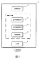
- FIG. 1 is a configuration diagram illustrating an HDR image synthesis system according to the first embodiment.
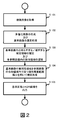
- FIG. 2 is a flowchart showing processing operations performed in the HDR image composition system according to the first embodiment.
- FIG. 3 is an explanatory diagram showing the luminance component relationship and threshold value set in the input image.
- (A) illustrates the threshold for ternarization.
- (B) illustrates the threshold value for quinarization.
- FIG. 4 is a diagram showing three input images used for explaining the operation.
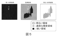
- FIG. 5 is a view showing an image obtained by ternizing the input image shown in FIG.
- FIG. 6 is a diagram illustrating image portions corresponding to an area that is too bright and an area that is too dark in the base image extracted from the reference image illustrated in FIG. 4.
- FIG. 5 is a view showing an image obtained by ternizing the input image shown in FIG.
- FIG. 6 is a diagram illustrating image portions corresponding to an area that is too bright and an area that is too dark in the base image extracted from the
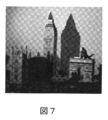
- FIG. 7 is a view showing an image in which the image portion shown in FIG. 6 is incorporated into a reference image.
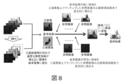
- FIG. 8 is a conceptual diagram illustrating HDR image processing with five input images.
- FIG. 9 is a diagram showing a composite image obtained by the HDR image processing shown in FIG.
- FIG. 10 is a flowchart showing the overall processing operation of one embodiment.
- FIG. 11 is a flowchart showing the processing operation for complementing the dark area in one embodiment.
- FIG. 12 is a flowchart showing the processing operation for complementing the bright area of one embodiment.
- FIG. 13 is a diagram showing an example of an image generated by the entire processing operation shown in FIG.
- FIG. 14 is a configuration diagram illustrating an HDR image synthesis system according to an embodiment.
- FIG. 1 is a configuration diagram showing an HDR image synthesis system 1 according to the first embodiment.
- the HDR image composition system 1 according to the first embodiment includes an image receiving unit 10, a reference image selection unit 20 that operates as an image composition unit, a complementary region search unit 30, a complement processing unit 40, and an output unit 50.
- the image receiving unit 10 receives a plurality of images having different luminance components as input images.
- the input image may be prepared by setting a different exposure condition and acquiring a plurality of images, for example.
- a processing operation for synthesizing an image using a luminance component will be described, but the present invention is not limited to this.
- Similar image composition may be performed using the V component (lightness component) in the HSV color space. That is, the maximum value of brightness in the RGB color space may be defined instead of the luminance component, and the following image composition processing may be performed based on this value.
- Each image received as an input image uses an image group acquired so that the characteristics of the imaging target appear in terms of luminance.
- Each image can be divided into at least three values: an area that is too bright, an area that is appropriately bright, and an area that is too dark, and the boundary luminance between the area where the luminance component in each image is too bright and the area that is appropriate Are prepared so as to have a luminance component relationship that is aligned with the boundary luminance between an appropriate brightness region and a region that is too dark in a darker image that is adjacent in luminance.
- the division range based on the luminance component of each image is reflected in a corrected image described later.
- the reference image selection unit 20 selects a reference image from the input images. As the reference image, one image may be selected from the input image by an arbitrary method. It is also possible to accept an image selection approaching a person.
- the reference image may be determined by comparing the amounts of the respective divided ranges of the corrected images. For example, in the case of ternary classification, selection processing may be performed so that an image having an appropriate brightness region having the maximum area is defined as the reference image. It is also possible not to select an image having a predetermined amount or more of an area that is too bright / too dark. Further, it is also possible to accept designation of an arbitrary range in the image and determine an image in which an appropriate brightness region has the maximum area within the designated range between images as the reference image.
- the supplementary area search unit 30 refers to the corrected image that has been multi-valued for each luminance component section of each image, and includes the remaining images as reference images with respect to the base image, and is included in each corrected image.
- the corrected image used in this processing is an image obtained by performing multi-value processing on each input image for each luminance component section.
- This corrected image may be captured from the image receiving unit 10 as a corresponding corrected image together with each image of the input image, or may be generated in the image composition unit.
- the reference image selection unit 20 may generate the image as in a processing example described later.
- a segment range based on the luminance component of each image appears.
- the classification range is ternary, the content of each correction image is classified into three categories: an area that is too bright, an appropriate brightness area, and an area that is too dark.
- This excessively bright area corresponds to an area having a higher luminance than a predetermined reference value including a “out-of-white” area in a conventional expression.
- a region that is too dark corresponds to a region whose luminance is lower than a predetermined reference value including a “blackout” region in conventional expression.
- a suitable brightness area refers to everything between areas that are too bright and areas that are too dark.
- Both predetermined criteria of each image correspond to the boundary brightness of an area that is too bright, an appropriate brightness area, and an area that is too dark.
- Each threshold value is set stepwise between images that are adjacent in terms of luminance, and is set so as to cover the desired luminance of many scenes.
- an appropriate brightness region of a darker image in which the boundary luminance between the brightness component of the brightness component in each image and the appropriate brightness region is adjacent in terms of luminance It is set for each image so that it is aligned with the boundary luminance of a region that is too dark.
- the upper and lower limits of the boundary luminance region between the too bright region and the appropriate brightness region, and the boundary region between the appropriate brightness region and the too dark region may be set as threshold values, and a quinary image that is quinary may be used as the correction image. Good.
- a quinary image When a quinary image is used as a corrected image, it becomes easy to align the boundary luminance between an appropriate brightness region and a region that is too dark in a darker image that is adjacent in terms of luminance. In other words, it is easy to acquire an image group that is accepted as an input image. For example, when imaging with a plurality of cameras, there is a margin in the setting of each camera. Further, by treating the luminance ranges within the upper and lower thresholds so as to be included in any brightness region, ambiguity can be imparted to the region shape mapping processing by the complementary region search unit 30. As a result, the appearance of the HDR image is improved.
- the complement processing unit 40 is an area obtained by matching an image portion of the original image corresponding to an area that is too bright and / or an area that is too dark in the corrected image of the reference image, and an appropriate brightness area in each reference image. Complement processing is performed using the corresponding image portion.
- the matching image portion in the reference image may be corrected for the size and the pixel arrangement angle due to the difference in the imaging position at the time of / after extraction of the partial image. This correction makes it possible to absorb, for example, a difference in the number of imaging pixels between imaging elements, a difference in acquisition resolution, a difference in imaging angle, and the like.
- the difference in imaging position and angle may be adjusted from the shape of the object reflected inside, or the positional relationship between the imaging elements at the time of imaging and the imaging time relationship between images are acquired as known information. May be used. Any method may be used for this correction.
- the reference image complementing process is repeated for each reference image. As a result, an HDR image having a more visible range is formed.
- the interpolation process is repeated by repeating an image portion corresponding to an area that is too bright and / or an area that is too dark in the selected reference image in order from a reference image that is brighter than the reference image to a reference image that is further away from the reference image. It can be done efficiently.
- an image portion corresponding to an area that is too bright and / or too dark that needs to be complemented in the selected reference image is arranged in order from the reference image that is farthest from the reference image to the reference image that is closest to the brightness.
- An HDR image that may be repeated is obtained. Note that, as a method for performing the complementing process, in the above-described method, the method for performing the complementing process using only the luminance value itself of the image has been described, but the present invention is not limited to this.
- the complementing process may be performed using not only the brightness value of the image itself but also the brightness gradient value of the image. More specifically, for example, two types of images, that is, an image that complements the brightness value in the reference image and an image that complements the brightness gradient value in the reference image are generated, and Poisson synthesis is performed using these images. Images may be combined. As a method using Poisson synthesis, for example, the method described in Non-Patent Document 1 may be used. In addition, a luminance adjustment process based on the luminance of the standard image may be added to each partial image reflected in the standard image acquired from each reference image. The above processes can be used in appropriate combination.
- each of the partial images of the brightness-adjusted areas may be obtained by sequentially subtracting the appropriate brightness area from the partial image obtained from the reference image that is close in luminance to the image area corresponding to the too bright area and / or the too dark area of the standard image. What is necessary is just to complement so that it may overlap and leave.
- the output unit 50 outputs the generated HDR image to the storage unit or the display unit in a required form. Further, a reference image may be output together with the generated HDR image. With such a configuration, even if different imaging factors (for example, an imaging positional relationship, temporal relationship, and synchronization relationship are indefinite) are included, a good high dynamic range image can be obtained from a plurality of images having different luminance components. Obtainable.
- FIG. 2 shows an example of an image processing flow performed in the HDR image synthesis system 1.
- This processing flow and the processing flow to be described later are examples, and if the order of processing is changed, the repetition method of each processing, the method applied to each processing, the number of images to be processed, etc. are appropriately changed and read as necessary.
- the image receiving unit 10 acquires a plurality of images that become a reference image and a reference image, which will be described later, as input images (S101).
- input images S101
- five images are accepted as input images. These five images are acquired or processed so that the adjacent relationship is established with respect to the luminance component relationship when each image is divided in terms of luminance.
- the reference image selection unit 20 divides each image description into at least three areas, that is, an area that is too bright, an appropriate brightness area, and an area that is too dark, for each luminance component, and shows each area. Is generated as a corrected image of each image (S102-1).
- the reference image selection unit 20 selects an image in which an appropriate brightness region has the maximum area from each image, and determines the image as a reference image (S102-2).
- the complementary area search unit 30 identifies areas that are too bright and areas that are too dark in the reference image as the areas to be complemented (S103-1).
- the complementary region search unit 30 sets the corresponding region in the reference image corresponding to the complementary target region in the standard image to the shape of each range (segmented) that is included in each corrected image in a luminance piecewise manner. It is derived by comparing the shapes of the respective regions formed (S103-2). Note that the robustness of the mapping can be improved by adding ambiguity to the boundary luminance range using a quinary image or a larger multi-value image.
- the complement processing unit 40 uses an image portion corresponding to an appropriate brightness area in an area that can be matched with a complement target area (an area that is too bright and an area that is too dark) of the reference image in each reference image.
- Complement processing is performed (S104).
- the complementing process may be repeated for each reference image for each of the too bright area and the too dark area of the standard image.
- images acquired from different reference images for the same region may be identified by image analysis.
- priority may be given to an image part having a wide appropriate brightness area, or a change in luminance with the edge of the corresponding area of the reference image may be large / small, too large / too small.
- the repetition of the complementing process is repeated until the region to be complemented as a reference image farther away from the reference image that is closer to the reference image in terms of brightness is filled in the individual image portions corresponding to the regions to be complemented in the selected standard image. Can be done efficiently.
- the repetition of the complementing process is repeated until the area to be complemented as a reference image closer to the reference image closer to the reference image that is farthest from the reference image is filled with each image portion corresponding to the region to be complemented in the selected standard image. Can be done efficiently.
- there is a difference in the appearance of the generated HDR image so a mechanism for allowing the user to select may be provided.
- the output unit 50 outputs the selected reference image and the generated HDR image to the storage unit or the display unit (S105).
- HDR images may be generated by a plurality of types of algorithms and displayed simultaneously.
- FIG. 3 is an explanatory diagram showing a luminance component relationship set between images used as input images.
- FIG. 3A shows that the number of input images is “3” and the number of luminance divisions is “3”. In other words, it represents the luminance component relationship of three ternary corrected images. “Long”, “middle”, and “short” in the explanatory diagrams indicate images having different exposure times, and “short” is the darkest image.
- the three images may be images having a difference in luminance using, for example, a difference in ISO sensitivity of the image sensor or image processing. By establishing this combination by adjusting exposure conditions, each image may depict a different appropriate luminance region.
- each image is divided into threshold values set in three areas: a bright area, a moderate brightness area, and a dark area.
- each threshold value is a boundary luminance (threshold value) between a moderate brightness region and a dark region in a darker image in which the boundary luminance (threshold value) between the bright region and the appropriate brightness region in each image is adjacent in terms of luminance.
- the boundary luminance (threshold value b3) between the bright region and the moderate brightness region in the diagram “long” in the explanatory diagram is the boundary between the moderate brightness region and the dark region in the diagram “middle” that are adjacent in terms of luminance. It is set to match the luminance (threshold value b3).
- the threshold b1 is set so as to match the boundary luminance in FIG. 3B shows the number of input images as “3” and the number of luminance divisions as “5”. In other words, it represents the luminance component relationship of three quinary corrected images.
- a luminance buffer area is set between the bright area and the moderate brightness area, and between the moderate brightness area and the dark area, with an upper limit value and a lower limit value using threshold values.
- Each input image is prepared based on the number of sections to be given to the corrected image generated in this way.
- FIG. 4 shows three input images. The three images are combined. Each image corresponds to a bright image, a dark image, or an intermediate image. As described above, each image has a luminance component relationship in which the boundary luminance when ternarization is performed is uniform.
- the HDR image composition system 1 accepts these three figures as an input image and selects a reference image.
- the intermediate image is selected as the standard image, and the remaining two images are used as reference images.
- the HDR image synthesis system 1 prepares a ternary image (corrected image) of each image.
- FIG. 5 is an image obtained by ternizing the input image shown in FIG.
- the same image is used for the angle of view, for example, even images acquired at different angles of view on the left and right and top and bottom can be combined.
- the boundaries appearing in FIG. 5 are each composed of two threshold values (upper limit and lower limit).
- the HDR image synthesis system 1 refers to the corrected image of the reference image, and identifies regions to be complemented (regions that are too bright and regions that are too dark). In the example of FIG.
- partial group of clock tower in the corrected image of the reference image, “partial group of clock tower” can be identified as an area that is too bright, and “shadow area of each structure” can be identified as an area that is too dark.
- dark reference image there is no region that is too bright, and as a result, a binary image is obtained.
- a bright reference image does not have an area that is too bright, and as a result, is a binary image.
- the HDR image synthesis system 1 extracts the shape of each segmentable region included in each corrected image.
- Each region extracted from each corrected image may be subjected to a smoothing process on its shape.
- the shape of each segmentable area included in the extracted corrected image of the standard image is compared with the shape of each segmentable area included in the corrected image of the reference image, and a matching area is determined.
- Explore In the matching process, for example, each shape of “part of the clock tower region group” identified by the ternary image as an excessively bright region in the standard image is searched from the corrected image of the dark reference image.
- a “shadow region of each structure” identified by the ternary image as an excessively dark region in the standard image is searched from the corrected image of the bright reference image.
- FIG. 6 is an image portion extracted from each reference image as an area corresponding to an area that is too bright and an area that is too dark in the reference image from the reference image shown in FIG. Since this image has the luminance characteristics between the images described above, a portion corresponding to an appropriate brightness region is included more than the reference image.
- an image portion of an area that is too bright and / or an area that is too dark in the corrected image of the standard image is complemented using a partial image of the matched area in the reference image.
- the region that is too bright and the region that is too dark are complemented once.
- FIG. 7 is an image in which an image part to be combined with the complementary region shown in FIG. 6 is incorporated in a reference image.
- FIGS. 8 and 9 are a conceptual diagram illustrating HDR image processing with five input images and a composite image thereof. In this image composition processing, an image portion corresponding to an area that is too bright or too dark in the corrected image of the standard image is first complemented with an image adjacent in terms of luminance, and the remaining reference image is further added to the complemented result image. Were used one by one and complemented.
- an image portion corresponding to an appropriate brightness region in each reference image remains in an accumulated manner.
- the brightness adjustment is performed by matching the reference image side with the standard image.
- humans can identify the detailed structure of the clock tower and the color and pattern of the building hidden behind the shadow in the reference image.
- the matching is described by comparing each luminance region shape of the multi-valued image.
- the matching process between the shapes can be changed to a matching process reflecting the image contents (pixel contents) in each region using the following cost function (1).
- E ⁇ (P) is the total matching cost of each luminance region shape.
- E shape (P) is a cost function part searched by exclusive OR, and can be expressed by the following equation (2), for example.
- E texture (P) is a cost function part searched by weighted SSD, and can be expressed by the following equation (3), for example.
- ⁇ is a weight variable for manipulating the balance of two cost functions.
- a smoothness term relating to the displacement p of each luminance region shape may be introduced. More specifically, for example, the smoothness term may be designed so as to have a smaller value as the displacements of the luminance region shapes are equal, as in the following equation (4). However, here, the sum of costs may be taken for all pairs of luminance area shapes.
- ⁇ is a parameter indicating the size of the smoothness term.
- ⁇ d ( ⁇ i , ⁇ j ) Is a weight for adjusting the strength of the smoothness term of the luminance area shape i and the luminance area shape j.
- the weighting factor may be designed so that the value decreases as the distance between the center of gravity of the luminance area shape i and the luminance area shape j increases.
- the following iterative process may be performed. First, the displacement p is calculated independently for each luminance region shape using Equation (1). Next, for a displacement other than a certain luminance region shape (for example, j) that is arbitrarily selected, the value is fixed, and only the displacement of the selected luminance region shape is determined using Equation (4). Repeat several times. When the change in the value of Expression (4) becomes sufficiently small by the iterative process, the iterative process is terminated and the obtained displacement p is set as the approximate optimum solution of Expression (4).
- FIG. 10 is a flowchart showing the overall processing operation of one embodiment.
- FIG. 11 is a flowchart showing the processing operation for complementing the dark area in one embodiment.
- FIG. 12 is a flowchart showing the processing operation for complementing the bright area of one embodiment.
- the HDR image composition system information processing apparatus
- the image groups are rearranged according to the luminance order.
- the images may be rearranged in the order of exposure times at the time of image capturing and numbered from 1 to n.
- the input image has the boundary brightness between the appropriate brightness area and the too dark area of a darker image in which the boundary brightness between the brightness area and the brightness area of the brightness component in each image is adjacent in terms of brightness. (It has the same luminance component relationship.)
- the five images shown in FIG. 10 are input images obtained by capturing images with different exposures using a plurality of cameras. When this image group is rearranged, the order of image 3 ⁇ image 5 ⁇ image 1 ⁇ image 2 ⁇ image 4 is in order of long exposure time. The home position is depicted at a different position for each image.
- the HDR image composition system generates a ternary image of each image of the input image (S1002).
- “too bright area”, “appropriate brightness area”, and “too dark area” of each image are determined.
- Each area is set as an “too bright area mask”, “appropriate brightness area mask”, and “too dark area mask”.
- Each mask is information indicating an area that is not changed by being superimposed on the original image.
- the HDR image synthesizing system refers to an appropriate amount of luminance area, receives a house part designation, etc., and selects a reference image from the input image (S1003).
- areas that are not masked by the “appropriate brightness area mask” of the reference image are selected as complementary areas.
- regions that do not correspond to the “appropriate brightness region” of the reference image (“too bright region” and “too dark region”) are selected as the complementary regions.
- the image 1 is selected as the reference image.
- the HDR image synthesizing system sequentially complements the regions of the “too bright region mask” and the “too dark region mask” of the standard image using the images of the mask regions that are matched in each reference image (S1004). ), (S1005). This process will be described in detail with reference to FIGS.
- n is the number numbered previously (“No. 3” in this example), and the selected reference image is “No. 2”.
- “No. 1” is selected as the reference image.
- the HDR image composition system identifies each mask of the selected reference image and generates a reference mask in which the “too dark region mask” region and the “appropriate brightness region mask” are combined (S2002).
- the roof and wall (reference mask) of the house where the roof part of the house (appropriate brightness area mask) and the wall surface of the house (area mask that is too dark) are combined into the shape of each area of the multivalued image.
- the HDR image composition system compares and matches the “too dark region mask” of the base image with the generated “reference mask” and, if necessary, the individual “appropriate brightness region mask” of the reference image. A region is searched (S2003). At this time, robustness is improved by matching based on the pattern. By this processing, the roof and wall surface (too dark region mask) of the house in the standard image and the roof and wall surface (reference mask) of the house in the reference image are matched.
- the HDR image composition system uses the texture of the “reference mask” of the reference image of this turn and the individual “appropriate brightness region mask” of the reference image for the “too dark region” of the matched reference image.
- the reference image is updated by overwriting or synthesizing the image (S2004). By this processing, the roof and wall surface (too dark region mask) of the reference image house are overwritten or combined with the house roof and wall surface (reference mask) of the reference image.
- the HDR image composition system ends the process of complementing the dark area if there is no “too dark area” in the updated reference image or if “m” is the maximum value that can be taken, and the reference image to be used remains. Then, the process returns to S2001 and the next reference image is selected (S2005). With the next turn, no. A wall surface (reference mask) of one image is captured in the standard image.
- the image portion of the original image corresponding to the “too dark region” in the corrected image of the standard image is a region matched in the reference image and each Complementary processing can be performed using an image portion corresponding to “moderate brightness region” in the reference image.
- “n” is the number numbered previously (“No. 3” in this example), and the selected reference image is “No. 4”.
- “No. 5” is selected as the reference image.
- FIG. 3 img1 and reference image No. 4 (img2) and reference image No. 5 (img4) is shown.
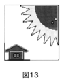
- the HDR image composition system identifies each mask of the selected reference image and generates a reference mask in which the “too bright region mask” region and the “appropriate brightness region mask” are combined (S3002).
- the periphery of the sun (reference mask) in which the sun (too bright region mask) and the extended portion (appropriate brightness region mask) in the drawing are combined is identified based on each region shape of the multi-valued image. If there are a large number of regions in the image, they are used in appropriate combination. Also, it is desirable to treat each distant area separately and treat each near area as a group of areas.
- the HDR image composition system compares and matches the “too bright region mask” of the base image with the generated “reference mask” and, if necessary, the individual “appropriate brightness region mask” of the reference image.
- a region is searched (S3003). At this time, accuracy is improved by matching based on the pattern.
- the periphery of the sun of the standard image region mask that is too bright matches the periphery of the sun of the reference image (reference mask). It should be noted that by using a multi-valued image of three or more values, the luminance boundary portion can be made ambiguous, and matching robustness is improved.
- the HDR image synthesis system uses the texture of the “reference mask” of the reference image of this turn and the individual “appropriate brightness region mask” of the reference image for the “overbright region” of the matched reference image.
- the reference image is updated by overwriting or synthesizing the image (S3004).
- the sun surroundings (too dark region mask) of the standard image is overwritten or combined with the roof and wall surface (reference mask) of the house of the reference image.
- the HDR image composition system ends the process of complementing the bright area if there is no “bright area” in the updated reference image or if “m” is the maximum value that can be taken, and the reference image to be used remains.
- the process returns to S3001 to select the next reference image (S3005).
- no. Five images of the sun inner surface (reference mask) are captured in the reference image.
- the image portion of the original image corresponding to the “too bright region” in the corrected image of the standard image is matched with each other in the reference image.
- Complementary processing can be performed using an image portion corresponding to “moderate brightness region” in the reference image.
- the HDR image composition system can generate an HDR image as shown in FIG.
- a high dynamic range image can be obtained as desired even if imaging factors such as an imaging position and time are different by inputting a plurality of images having characteristics in luminance relation. Can be obtained. This is to search a part of the reference image that matches the required area of the standard image, and to use the partial image of the search result to determine the required area of the standard image using an image of an appropriate brightness area in the reference image. This is to perform a complementary process.
- Each unit of the image processing system may be realized using a combination of hardware and software.
- an image processing program is developed in a RAM (Random Access Memory), and a control unit (CPU (Central Processing Unit)) or the like is based on the program.
- CPU Central Processing Unit
- the program may be recorded in a fixed manner on a recording medium and distributed.
- the program recorded on the recording medium is read into a memory via a wired, wireless, or recording medium itself, and operates a control unit or the like.
- Examples of the recording medium include an optical disk, a magnetic disk, a semiconductor memory device, and a hard disk. Further, all or a part of each part may be formed by constructing a circuit on an LSI.
- the specific configuration of the present invention is not limited to the above-described embodiment, and even if there is a change in a range that does not depart from the gist of the present invention, such as separation and merging of block configurations, replacement of procedures, and combinations of the embodiments It is included in this invention.
- a part or all of the above-described embodiments can be described as follows. Note that the following supplementary notes do not limit the present invention.
- An image receiving unit that receives a plurality of images having different luminance components as input images;
- a reference image selection unit for selecting a reference image from the plurality of images;
- each of the input images has a luminance
- the shape of each segmentable area included in the corrected image of the reference image and the distinguishable image included in the corrected image of the other image Using a shape of each region, a complementary region search unit for searching for a region where the shape matches, An image portion corresponding to an area that is too bright and / or an area that is too dark in the corrected image of the reference image is complemented with an image portion that is a matched area in the reference image and an appropriate brightness area in each reference image.
- a complementary processing unit that generates a composite image by processing;
- An output unit for outputting the generated composite image;
- each image can be divided into at least three values of a bright area, a moderate brightness area, and a dark area, and a bright area and a moderate brightness area of a luminance component in each image.
- the reference image selection unit selects, as a reference image, a high-order image having one or more large areas based on the entire surface of each image or the area of an appropriate brightness region within a predetermined range.
- the complementary area search unit uses the corrected image classified into three sections indicating a bright area, a moderate brightness area, and a dark area when performing a search process, Classification including a moderately bright area included in the corrected image of the image that is adjacent in terms of luminance based on the shape of the too bright area and / or the too dark area included in the corrected image of the reference image Matching the shape of each possible region and extracting a partial image in the reference image used for interpolation from the reference image An image processing system as described in the above supplementary note.
- E ⁇ (P 1 , ..., p N ) Is the total cost of all combinations of each luminance region shape pair
- E shape (P k ) Is the cost function part searched by exclusive OR
- E texture (P k ) Is a cost function part to search by weighted SSD
- ⁇ is a weight variable
- ⁇ is the size of the smoothness term related to the displacement p of each luminance region shape
- ⁇ d ( ⁇ i , ⁇ j ) Is a weight indicating the strength of the smoothness term of the luminance area shape i and the luminance area shape j.
- each of the input images has a luminance
- the shape of each segmentable area included in the corrected image of the reference image and the distinguishable image included in the corrected image of the other image search for a region where the shape matches, An image portion corresponding to an area that is too bright and / or an area that is too dark in the corrected image of the reference image is complemented by using an image portion that is a matching area in the reference image and an appropriate brightness area in each reference image.
- each image can be classified into at least three values of an area that is too bright, an area that is appropriately bright, and an area that is too dark, and an appropriate area that is too bright for the luminance component in each image.
- Use a group of images that have a luminance component relationship that matches the boundary luminance between the appropriate luminance region of a darker image and the region that is too dark in the boundary where the luminance of the bright region is adjacent in terms of luminance An image processing method by an information processing system.
- the information processing system selects, as a reference image, a high-order image having one or more wide areas based on the entire surface of each image or the area of an appropriate brightness area within a predetermined range.
- the information processing system uses the corrected image classified into three sections indicating a bright area, a moderate brightness area, and a dark area, Classification including a moderately bright area included in the corrected image of the image that is adjacent in terms of luminance based on the shape of the too bright area and / or the too dark area included in the corrected image of the reference image Matching the shape of each possible region and extracting a partial image in the reference image used for interpolation from the reference image An image processing method as described in the above supplementary note.
- the information processing system includes: Add brightness adjustment processing to each partial image for each area acquired from each reference image, The supplementary note described above, wherein each partial image of each area whose brightness has been adjusted is complemented after brightness adjustment of an appropriate brightness area portion is performed on an image part corresponding to an area that is too bright and / or too dark in the reference image.
- Image processing method [Appendix 24] The information processing system refers to the image content of the image portion corresponding to the appropriate brightness region in each reference image in the region matched with the standard image in the reference image, and the remaining all or part of the reference image The image processing method according to the above supplementary note, wherein a matching area is searched.
- the information processing system searches for a matching area in the reference image that satisfies the cost function (1) shown below when searching for a matching area between the reference image and the reference image.
- the information processing system searches for a matching area in the reference image that satisfies the cost function (4) shown below when searching for a matching area between the reference image and the reference image. The image processing method as described.
- E ⁇ (P 1 , ..., p N ) Is the total cost of all combinations of each luminance region shape pair
- E shape (P k ) Is the cost function part searched by exclusive OR
- E texture (P k ) Is a cost function part to search by weighted SSD
- ⁇ is a weight variable
- ⁇ is the size of the smoothness term related to the displacement p of each luminance region shape
- ⁇ d ( ⁇ i , ⁇ j ) Is a weight indicating the strength of the smoothness term of the luminance area shape i and the luminance area shape j.
- An image receiving unit that receives a plurality of images having different luminance components as input images;
- a reference image selection unit for selecting a reference image from the plurality of images;
- each of the input images has a luminance
- the corrected image obtained by multi-value processing for each component classification the shape of each segmentable area included in the corrected image of the reference image and the distinguishable image included in the corrected image of the other image
- a complementary region search unit for searching for a region where the shape matches, An image portion corresponding to an area that is too bright and / or an area that is too dark in the corrected image of the reference image is complemented with an image portion that is a matched area in the reference image and an appropriate brightness area in each reference image.
- a complementary processing unit that generates a composite image by processing;
- a program that operates as an output unit that outputs the generated composite image.
- each image can be classified into at least three values of a bright area, a moderate brightness area, and a dark area, and a bright area and a moderate brightness of the luminance component in each image.
- An image group having a luminance component relationship that matches the boundary luminance between a moderately bright region and a dark region of a darker image in which the boundary luminance of the region is adjacent in terms of luminance is used.
- the reference image selection unit selects, as a reference image, a high-order image having one or more wide areas based on the entire area of each image or the area of an appropriate brightness region within a predetermined range.
- the program according to the above supplementary note which is operated so as to perform selection processing.
- E ⁇ (P) is the total matching cost of each luminance region shape
- E shape (P) is a cost function part searched by exclusive OR
- E texture (P) is a cost function part searched by weighted SSD
- ⁇ is a weight variable.
- E ⁇ (P 1 , ..., p N ) Is the total cost of all combinations of each luminance region shape pair
- E shape (P k ) Is the cost function part searched by exclusive OR
- E texture (P k ) Is a cost function part to search by weighted SSD
- ⁇ is a weight variable
- ⁇ is the size of the smoothness term related to the displacement p of each luminance region shape
- ⁇ d ( ⁇ i , ⁇ j ) Is a weight indicating the strength of the smoothness term of the luminance area shape i and the luminance area shape j.
- HDR image composition system 10 Image reception unit (image reception means) 20 Reference image selection unit (reference image selection means) 30 Complementary region search unit (complementary region search means) 40 Complement processing part (complement processing means) 50 Output section (output means)
Landscapes
- Engineering & Computer Science (AREA)
- Multimedia (AREA)
- Signal Processing (AREA)
- Physics & Mathematics (AREA)
- General Physics & Mathematics (AREA)
- Theoretical Computer Science (AREA)
- Image Processing (AREA)
- Facsimile Image Signal Circuits (AREA)
- Studio Devices (AREA)
Abstract
Description
これらの技術は、例えば特許文献1ないし3に記載されている。
特許文献1に記載された手法では、露光量が異なる複数枚の入力画像を受け付けて、各々の画像の設定された輝度レンジの輝度値領域を抽出して、その領域を用いたHDR画像を生成している。また、当該文献に記載された手法では、複数の輝度レンジ設定値を用いて各々の画像からその設定値の輝度値領域を抽出して、多数のHDR画像を生成して、基準画像に組み合わせて最終的に出力するHDR画像を合成する。
特許文献2及び3に記載された手法でも、複数枚の入力画像を受け付けて、各々の入力画像から所望する領域を抽出して、基準画像の明る過ぎる領域と暗すぎる領域を埋めるように処理動作している。特許文献2の手法では、同一の撮像条件の複数枚の入力画像を取得して、同一画素部分の輝度を加算処理して重ね合わせることで、HDR画像を得ている。また、特許文献3の手法では、特殊な構造を有する撮像部を用いて、異なる露光条件の複数枚の入力画像を取得して、各々の画像を正規化と信頼性評価を行い、信頼性に従って画像合成することで、HDR画像を得ている。
非特許文献1は、後述する実施形態で採用可能なポアッソン合成手法を示している。
また、HDR画像を合成するにあたって異なる撮像素子を用いて、概ね同一画角、概ね同一焦点距離の条件下で、異なる露光量で複数画像を取得し、その一組の画像をHDR画像に合成する。
しかし、これらの手法には、幾つかの問題を見出せる。
その一つを例示すれば、合成する複数枚の画像を得る際に、上記条件を満たす必要がある。
より具体的に述べれば、1つの撮像素子を用いて複数画像を得るために異なる時間で撮影する必要が生じる。結果、移動する物体を被写体とした画像合成に良好な結果を得られない。また、合成に用いる露光量の異なる画像を増やせば増やすほど、時間間隔が開き、撮影条件を満たすことが困難と成りやすい。
他方、異なる撮像素子を用いれば、露出時間程度の差で粗同時的に複数枚の画像を得られるものの、同一画角、同一焦点距離等の撮影条件を厳しく管理して撮影する必要が生じる。結果、撮像素子や光学系を所要に連動させる機能が必要になる。
上記観点によって、特許文献1に記載された手法を検証すれば、同一撮像素子から露出量又は絞りを段階的に変化させながら入力画像群を得ている部分に弱点を見つける。このため、撮影では、異なる位置関係を含まないように撮像機器を固定するための脚立などの器具用いる必要性が生じている。
特許文献2に記載された手法も同様に、同一撮像素子から入力画像群を得ている部分に弱点がある。また、同一撮像条件で複数枚の入力画像を取得する為、撮像条件で黒つぶれと白とびが起きている部分について、当該文献の画像処理では補完されない。
特許文献3に記載された手法にも、撮像部から各入力画像を非破壊読み出しで同期させて次々得ている部分に弱点がある。換言すれば、撮像条件が多くの点で限定されている。
また、例示した撮像条件に関する制限事項の解消以外にも、より良好なHDR画像を作成する手法が望まれる。
そこで、本発明では、異なる撮像因子が含まれていても、異なる輝度成分を有する複数の画像から良好なハイダイナミックレンジ画像を得る画像処理システムを提供する。
本発明に係る画像処理方法は、異なる輝度成分を有する複数の画像を入力画像として受け付けて、前記複数の画像内から基準画像を選定すると共に、前記複数の画像内の他の画像を参照画像として用いて前記基準画像内の明るすぎる領域及び/又は暗すぎる領域を補完する部分画像を前記参照画像から抽出する際に、前記入力画像各々を輝度成分の区分毎に多値化処理した補正画像を用いて、前記基準画像の補正画像に含まれていた区分可能な各領域の形と前記他の画像の補正画像に含まれていた区分可能な各領域の形とを用いて、形状がマッチングする領域を探索処理し、前記基準画像の補正画像内で明るすぎる領域及び/又は暗すぎる領域にあたる画像部分を、前記参照画像内でマッチングした領域で且つ各々の参照画像内で適切な明るさ領域にあたる画像部分を用いて補完処理して、合成画像を生成する、ただし、前記入力画像として、各々の画像は、明るすぎる領域、適切な明るさ領域、暗すぎる領域の少なくとも3値に区分可能であり、且つ、各々の画像内の輝度成分の明るすぎる領域と適切な明るさ領域の境界輝度が輝度的に隣接関係にあるより暗い画像の適切な明るさ領域と暗すぎる領域の境界輝度に揃う輝度成分関係を有した画像群を用いることを特徴とする。
本発明に係るプログラムを記録したコンピュータ読み取り可能な記録媒体は、前記プログラムを非一時的に記録した記録媒体であって、前記プログラムは、情報処理システムを、異なる輝度成分を有する複数の画像を入力画像として受け付ける画像受付部と、前記複数の画像内から基準画像を選定する基準画像選定部と、前記複数の画像内の他の画像を参照画像として用いて前記基準画像内の明るすぎる領域及び/又は暗すぎる領域を補完する部分画像を前記参照画像から抽出する際に、前記入力画像各々を輝度成分の区分毎に多値化処理した補正画像を用いて、前記基準画像の補正画像に含まれていた区分可能な各領域の形と前記他の画像の補正画像に含まれていた区分可能な各領域の形とを用いて、形状がマッチングする領域を探索処理する補完領域探索部と、前記基準画像の補正画像内で明るすぎる領域及び/又は暗すぎる領域にあたる画像部分を、前記参照画像内でマッチングした領域で且つ各々の参照画像内で適度な明るさ領域にあたる画像部分を用いて補完処理することにより、合成画像を生成する補完処理部と、生成した前記合成画像を出力する出力部として動作させることを特徴とし、前記入力画像の条件として、各々の画像は、明るい領域、適度な明るさ領域、暗い領域の少なくとも3値に区分可能であり、且つ、各々の画像内の輝度成分の明るい領域と適度な明るさ領域の境界輝度が輝度的に隣接関係にあるより暗い画像の適度な明るさ領域と暗い領域の境界輝度に揃う輝度成分関係を有した画像群を用いる。
図2は、第1の実施形態に係るHDR画像合成システムで行われる処理動作を示したフローチャートである。
図3は、入力画像に設定される輝度成分関係と閾値を表した説明図である。(a)は、3値化用閾値を例示する。(b)は、5値化用閾値を例示する。
図4は、動作説明に用いる3枚の入力画像を示した図である。
図5は、図4に示した入力画像を3値化した画像を示した図である。
図6は、図4に示した参照画像内から抽出された基準画像の明るすぎる領域及び暗すぎる領域に当たる画像部分を示した図である。
図7は、図6で示した画像部分を基準画像に組み入れた画像を示した図である。
図8は、入力画像を5枚にしてHDR画像処理を説明する概念図である。
図9は、図8に示したHDR画像処理で得られる合成画像を示した図である。
図10は、一実施例の全体の処理動作を示したフローチャートである。
図11は、一実施例の暗部領域を補完する処理動作を示したフローチャートである。
図12は、一実施例の明部領域を補完する処理動作を示したフローチャートである。
図13は、図10で示した全体の処理動作で生成される画像例を示した図である。
図14は、一実施例に係るHDR画像合成システムを示す構成図である。
[第1の実施形態]
図1は、第1の実施形態に係るHDR画像合成システム1を示す構成図である。
第1の実施形態に係るHDR画像合成システム1は、画像受付部10と、画像合成手段として動作させる基準画像選定部20、補完領域探索部30、補完処理部40と、出力部50を含み構成されている。
画像受付部10は、異なる輝度成分を有する複数の画像を入力画像として受け付ける。入力画像は、例えば異なる露出条件を設定して複数の画像を取得することで準備してもよい。
なお、以下では輝度成分を用いて画像合成を行う処理動作について述べるが、本発明はこれに限定されない。例えば、YUV色空間におけるY成分(輝度成分)を用いる代わりに、HSV色空間におけるV成分(明度成分)を用いて同様の画像合成を行ってもよい。すなわちRGB色空間における明度の最大値を輝度成分の代わりに定義し、この値によって、以下の画像合成処理を行ってもよい。
入力画像として受け付ける各々の画像は、輝度的に撮像対象の特徴が表れる様に取得した画像群を用いる。各々の画像は、明るすぎる領域、適切な明るさ領域、暗すぎる領域の少なくとも3値に区分可能であり、且つ、各々の画像内の輝度成分の明るすぎる領域と適切な明るさ領域の境界輝度が輝度的に隣接関係にあるより暗い画像の適切な明るさ領域と暗すぎる領域の境界輝度に揃う輝度成分関係を有するように準備される。
各画像の輝度成分による区分範囲は、後述する補正画像に反映される。
基準画像選定部20は、入力画像の中から基準画像を選定する。基準画像は、入力画像から任意の手法で1画像を選定すればよい。また、人間に寄る画像選定を受け付けることとしてもよい。また、各補正画像の各区分範囲の量を比較して、基準画像を定めてもよい。例えば、3値区分であれば適切な明るさ領域が最大面積を有している画像を基準画像に定めるように選定処理すればよい。また、明るすぎる領域/暗すぎる領域が所定量以上ある画像は基準画像に選定しないようにすることも可能である。また、画像内の任意範囲の指定を受け付けて、画像間の指定範囲内で適切な明るさ領域が最大面積を有している画像を基準画像に定めるようにしてもよい。
補完領域探索部30は、各画像の輝度成分区分毎に多値化処理されている補正画像を参照して、基準画像に対して残りの各画像を参照画像として、各補正画像に含まれていた区分可能な各領域の形を対比することによって、区分できた領域の成した形状でマッチングする画像間の領域部分を導出する。
この処理で用いられる補正画像は、入力画像各々を輝度成分の区分毎に多値化処理して得た画像である。この補正画像は、入力画像の各画像と共に対応する補正画像として画像受付部10から取り込んでも良いし、画像合成部内で生成してもよい。例えば、後述する処理例のように基準画像選定部20が生成することとすればよい。
補正画像には、各画像の輝度成分による区分範囲が表れている。区分範囲を3値とした場合、各補正画像の内容には、明るすぎる領域、適切な明るさ領域、暗すぎる領域の3つの区分に分類される。
この明るすぎる領域は、慣用的表現で“白飛び”領域を含む所定基準値よりも輝度が高い領域に当たる。
また、暗すぎる領域は、慣用的表現では“黒つぶれ”領域を含む所定基準値よりも輝度が低い領域に当たる。
適切な明るさ領域は、明るすぎる領域と暗すぎる領域の間全てを指す。
各画像の両所定基準は、明るすぎる領域、適切な明るさ領域、暗すぎる領域の境界輝度にあたる。各閾値は、輝度的に隣接関係にある画像間で段階的に設定され、多くのシーンの所望輝度を網羅するように設定する。
3値化画像を補正画像として用いる場合は、各々の画像内の輝度成分の明るすぎる領域と適切な明るさ領域の境界輝度が輝度的に隣接関係にあるより暗い画像の適切な明るさ領域と暗すぎる領域の境界輝度に揃うように、各画像に対して設定する。
また、明るすぎる領域と適切な明るさ領域、適切な明るさ領域と暗すぎる領域の境界輝度領域についての上限と下限を閾値で定め、5値化した5値化画像を補正画像として用いてもよい。5値化画像を補正画像として用いる場合では、輝度的に隣接関係にあるより暗い画像の適切な明るさ領域と暗すぎる領域の境界輝度を揃え易く成る。換言すれば、入力画像として受け付ける画像群の取得が容易になる。例えば、複数台のカメラで撮像する際に、各々のカメラの設定に余裕が生まれる。また、各々の上限と下限の閾値内の輝度範囲について何れの明るさ領域にも含まれるように扱うことによって、補完領域探索部30による領域形状のマッピング処理に曖昧性を付与できる。その結果、HDR画像の見栄えが良くなる。
また、7値化画像などの多値化画像を用いて、領域形状のマッピング処理の位置調整精度をより高めたり、基準画像の補完領域を参照画像のより適切な明るさ領域で置換や合成することしてもよい。
補完処理部40は、基準画像の補正画像内で明るすぎる領域及び/又は暗すぎる領域にあたる元画像の画像部分を、参照画像内でマッチングした領域で且つ各々の参照画像内で適切な明るさ領域にあたる画像部分を用いて補完処理する。
この補完処理では、例えば基準画像の暗すぎる領域/明るすぎる領域を参照画像内の該当部分画像(マッチングした領域画像)で置き換えたり、相互の領域内の画像で合成したりすれば、基準画像で暗すぎた/明るすぎた部分が輝度的に見やすく補完される。
この際、補完処理の一部として、参照画像内のマッチング画像部分を、該部分画像の抽出時/抽出後に、撮像位置の違いによる大きさや画素並びの角度を補整してもよい。この補整によって、例えば撮像素子間の撮像画素数の違いや、取得解像度の違い、撮像角度の違いなどを吸収することが可能になる。撮像位置や角度の違いは、内部に写り込んでいる対象の形状から調整してもよいし、撮像した際の撮像素子間の位置関係や画像間の撮像時間関係などを既知情報として取得して利用してもよい。この補整としてはどのような方式を用いてもよい。
基準画像の補完処理は、参照画像毎に繰り返し行なう。このことによってより見える範囲が増したHDR画像が形成される。
補完処理の繰り返しは、選定された基準画像内で補完を要する明るすぎる領域及び/又は暗すぎる領域にあたる画像部分を、基準画像に輝度的に近い参照画像からより遠い参照画像とする順に繰り返すことで効率的に行える。
また、補完すべき領域が無くなった際に、補完処理をその方向(明るすぎる領域方向又は暗すぎる領域方向)に対する繰り返しを停止する仕組みがあってもよい。
補完処理の繰り返しは、選定された基準画像内で補完を要する明るすぎる領域及び/又は暗すぎる領域にあたる画像部分を、基準画像から輝度的に最も遠い参照画像からより近い参照画像に寄ってくる順に繰り返すことを行っても良いHDR画像が得られる。
なお、補完処理を行う方法として、上述方法では、画像の輝度値の値そのものだけを用いて補完処理を行う方法について述べたが、本発明はこれに限定されない。例えば、補完処理を行う際に、画像の輝度値の値そのものだけでなく、画像の輝度勾配の値を用いて補完処理を行ってもよい。より具体的には、例えば、基準画像内で輝度値の値を補完した画像と、基準画像内での輝度勾配値を補完した画像の2種類を生成し、これらの画像を用いてポアッソン合成を用いて画像を合成してもよい。ポアッソン合成を用いる方法としては、例えば、非特許文献1に記載の方法を用いればよい。
また、各参照画像から取得した基準画像に反映させる各部分画像に、基準画像の輝度を踏まえた輝度調整処理を加える構成にしてもよい。
上記各処理は適切に組み合わせて用いることも可能である。例えば、輝度調整された各領域の各部分画像を基準画像の明るすぎる領域及び/又は暗すぎる領域にあたる画像部分に輝度的に近い参照画像から得た部分画像から順に適切な明るさ領域の部分を残して重ね合わせるように補完すればよい。出力部50は、生成したHDR画像を所要な形態で記憶部や表示部に出力する。また、生成したHDR画像に併せて基準画像も出力することとしてもよい。
このような構成によって、異なる撮像因子(例えば撮像の位置関係や時間関係、同期関係が不定的な関係)が含まれていても、異なる輝度成分を有する複数の画像から良好なハイダイナミックレンジ画像を得ることができる。
[画像処理フロー]
次に、HDR画像合成処理について説明する。
図2では、HDR画像合成システム1で行われる画像処理フロー例を示している。なお、本処理フローや後述する処理フローは例示であり、処理の順序の入れ替えや、各処理の繰り返し方法、各処理に適用する方式、処理する画像枚数などは所要に適宜変更して読みかえればよい。
画像受付部10は、後述する基準画像と参照画像になる複数の画像を入力画像として取得する(S101)。
本画像合成処理では、入力画像として5枚の画像を受け付ける。この5枚の画像は、各々の画像を輝度的に区分した際に、輝度成分関係について隣接関係が成立するように取得もしくは加工されている。この画像群の有する輝度成分関係については別途後述する。
次に、基準画像選定部20は、各画像の描写を、明るすぎる領域、適切な明るさ領域、暗すぎる領域の少なくとも3つの領域に、輝度成分毎に区分して、各領域を示した画像を各画像の補正画像として生成する(S102−1)。
次に、基準画像選定部20は、各画像の中から適切な明るさ領域が最大面積を有している画像を選定して、該画像を基準画像に定める(S102−2)。
次に、補完領域探索部30は、補完対象領域として、基準画像内の明るすぎる領域と暗すぎる領域を、それぞれ識別する(S103−1)。この明るすぎる領域と暗すぎる領域は、多値化処理されている各画像の補正画像を参照すれば容易に取得できる。
次に、補完領域探索部30は、基準画像内の補完対象領域に対応する参照画像内の該当領域を、各補正画像に含まれていた輝度区分的に連続している各範囲の形状(区分できた各領域の形状)をそれぞれ対比することによって、導出する(S103−2)。なお、5値化画像やより大きな多値化画像を用いて境界輝度範囲に曖昧性を付与することで、マッピングのロバスト性を向上させ得る。
次に、補完処理部40は、基準画像の補完対象領域(明るすぎる領域と暗すぎる領域)を、各参照画像内でマッチングできた領域内にある適切な明るさ領域にあたる画像部分を利用して補完処理する(S104)。この際、基準画像の明るすぎる領域と暗すぎる領域のそれぞれに対して参照画像1枚毎に補完処理を繰り返すことを行えばよい。また、同一領域に対する異なる参照画像から取得した画像は画像解析によって何れを採用するか識別してもよい。この際、適切な明るさ領域が広い画像部分を優先したり、基準画像の該当領域端との輝度変化が大きい/少ない、大きすぎる/少なすぎるなどを考慮してもよい。
なお、補完処理の繰り返しは、選定された基準画像内で補完する領域にあたる個々の画像部分を、基準画像に輝度的に近い参照画像からより遠い参照画像として補完すべき領域が埋まり切るまで繰り返すことで効率的に行える。
また、補完処理の繰り返しは、選定された基準画像内で補完する領域にあたる個々の画像部分を、基準画像から輝度的に最も遠い参照画像からより近い参照画像として補完すべき領域が埋まり切るまで繰り返すことで効率的に行える。
上記両処理の何れの順を採用するかで、生成されるHDR画像の見え方に差が生じるため、ユーザに選択させる仕組みを設けてもよい。また、補完する明るすぎる領域と暗すぎる領域のそれぞれに異なるアルゴリズムを用いてもよい。例えば、明るすぎる領域はより近い参照画像から順に参照し、暗すぎる領域は最も遠い参照画像から順に参照することすればよい。
また、例えば、ユーザから被写体の選択を受けて、採用するアルゴリズムを変化させることを行ってもよい。
次に、出力部50は、選定した基準画像と、生成したHDR画像を記憶部や表示部に出力する(S105)。HDR画像を複数種類のアルゴリズムで生成して、同時に表示するようにしてもよい。
上記処理動作が行なわれることによって、複数の画像から、選定された基準画像の輝度的に見えにくい領域を補完して、良好なHDR画像が得られる。
ここで、入力画像(画像群)の有する輝度成分関係について説明する。
図3は、入力画像として用いる画像間に設定される輝度成分関係を表した説明図である。図3(a)は、入力画像数を『3』として、輝度的区分数も『3』を示している。換言すれば、3枚の3値化した補正画像が有する輝度成分関係を表している。
説明図中の“long”、“middle”、“short”は、露光時間の異なる画像を示しており“short”が一番暗い画像になる。3枚の画像は、露光時間以外にも、例えば撮像素子のISO感度の差や画像処理などを用いて輝度的違いを付けた画像でもよい。この組み合わせを露出条件の調整などを行って成立させることによって、各画像はそれぞれ異なる適度な輝度領域を描写してもよい。
各々の画像は、明るい領域、適度な明るさ領域、暗い領域の3領域に設定されている閾値毎に区分されている。
また、各閾値は、各々の画像内の明るい領域と適度な明るさ領域の境界輝度(閾値)が輝度的に隣接関係にあるより暗い画像の適度な明るさ領域と暗い領域の境界輝度(閾値)に揃うように設定される。
例えば、説明図中の図“long”の明るい領域と適度な明るさ領域の境界輝度(閾値b3)は、輝度的に隣接関係にある図“middle”の適度な明るさ領域と暗い領域の境界輝度(閾値b3)に揃うように設定される。
図“middle”と図“short”との関係も同様であり、閾値b2で境界輝度が揃う設定である。仮に、更に暗い画像を取得する場合には、閾値b1で図“short”の境界輝度と揃う設定で取得する。
図3(b)は、入力画像数を『3』として、輝度的区分数も『5』を示している。換言すれば、3枚の5値化した補正画像が有する輝度成分関係を表している。各々の画像の、明るい領域と適度な明るさ領域との間、適度な明るさ領域と暗い領域との間に、輝度的緩衝領域が閾値を用いて上限値と下限値で設定されている。
このように生成する補正画像に持たせる区分数を踏まえ、各々の入力画像を準備する。
このような入力画像を画像合成処理に用いることで、異なる輝度成分を有する複数の画像から良好なハイダイナミックレンジ画像を得ることができる。
[処理例]
次に、本発明の処理動作例を画像処理結果を用いて説明する。説明を簡単にするため、入力画像は3枚、補正画像は3値化処理によって得る。
図4は、3枚の入力画像である。この3枚の画像を合成する。
各画像は、明るい画像、暗い画像、中間の画像にあたる。各画像は、先に説明したように3値化した際の境界輝度が揃う輝度成分関係を有している。
HDR画像合成システム1は、この3図を入力画像として受け付けて、基準画像を選定する。本例では中間画像を基準画像として選定し、残りの2画像を参照画像にする。
HDR画像合成システム1は、各画像の3値化画像(補正画像)を準備する。図5は、図4に示した入力画像を3値化した画像である。なお、本説明では画角は同一の画像を用いているものの、例えば左右や上下に異なる画角で取得した画像であっても合成できる。なお、5値化画像の場合は、図5中に現れている境界が各々2つの閾値(上限と下限)で境界が構成される。
次に、HDR画像合成システム1は、基準画像の補正画像を参照して、補完する領域(明るすぎる領域及び暗すぎる領域)を識別する。
なお、図5の例では、基準画像の補正画像では、明るすぎる領域として“時計台の一部の領域群”と、暗すぎる領域として“各構造物の影の領域”が識別できる。また、暗い参照画像では、明るすぎる領域は無く、結果的に2値画像になっている。また、明るい参照画像は、明るすぎる領域が無く、結果的に2値画像になっている。他方、明るい参照画像と暗い参照画像には、適度な輝度の領域が少ないことも分かる。
次に、HDR画像合成システム1は、基準画像内の補完する領域の画像として参照画像内の部分画像を用いるために、各補正画像に含まれていた区分可能な各領域の形を抽出する。各補正画像から抽出した各領域は、その形状について平滑化処理を行ってもよい。
次に、抽出した基準画像の補正画像に含まれていた区分可能な各領域の形と参照画像の補正画像に含まれていた区分可能な各領域の形とを比較して、一致する領域を探索する。マッチング処理は、例えば、基準画像内の明るすぎる領域として3値画像によって識別した“時計台の一部の領域群”の各々の形状を暗い参照画像の補正画像内からそれぞれ探索する。同様に、基準画像内の暗すぎる領域として3値画像によって識別した“各構造物の影の領域”を明るい参照画像の補正画像内から探索する。
図6は、図4に示した参照画像内から、基準画像の明るすぎる領域及び暗すぎる領域に当たる領域としてそれぞれの参照画像から抽出された画像部分である。この画像には、先に説明した画像間の有する輝度的特徴が有る為、適度な明るさ領域にあたる部分が基準画像よりも含まれる。
上記探索処理によって、基準画像の補正画像内で明るすぎる領域及び/又は暗すぎる領域の画像部分を、参照画像内でマッチングした領域の部分画像を用いて補完処理する。
本処理例の説明では、3画像であるので、中間画像が基準画像として選択された場合には、明るすぎる領域と暗すぎる領域とが1度ずつ補完処理される。他方、図4に示した暗い参照画像を選択した場合には、その暗すぎる領域を、中間画像と明るい画像とをそれぞれ用いて2度補完処理すればよい。
補完処理を適宜繰り返すことによって、より良いハイダイナミックレンジ合成画像が生成される。
図7は、図6で示した補完領域に組み合わせる画像部分を基準画像に組み入れた画像である。
図8及び図9は、入力画像を5枚にしてHDR画像処理を説明した概念図とその合成画像である。
この画像合成処理では、基準画像の補正画像内で明るすぎる領域又は暗すぎる領域にあたる画像部分を、輝度的に隣接した画像でまず補完処理し、その補完結果画像に対して、更に残りの参照画像を1枚ずつ用いて補完処理した。
最終結果の合成画像には各参照画像内で適度な明るさ領域にあたる画像部分が蓄積的に残っている。
また、参照画像の一部分を合成画像の一部として組み込む際に、参照画像側を基準画像に合わせて輝度調整を行っている。
結果として、合成画像は、基準画像では時計塔の細部構造や、影に隠れていた建物の色や模様を人間が識別可能になっている。
次に、補完領域探索部30で行う各領域のマッチング処理の最適化手法を説明する。上記説明では、マッチングを多値化画像の各輝度領域形状を比較することを説明した。この形状間のマッチング処理を以下のコスト関数(1)を用いて、各領域内の画像内容(画素内容)を反映させたマッチング処理に変更することも可能である。この方式によれば、よりロバスト性を有する探索精度を実現する。

Eshape(p)は排他的論理和で探索するコスト関数部分であり、例えば下記式(2)で表せる。
他方、Etexture(p)は重み付きSSDで探索するコスト関数部分であり、例えば下記式(3)で表せる。
αは、2つのコスト関数のバランスを操作するための重み変数である。
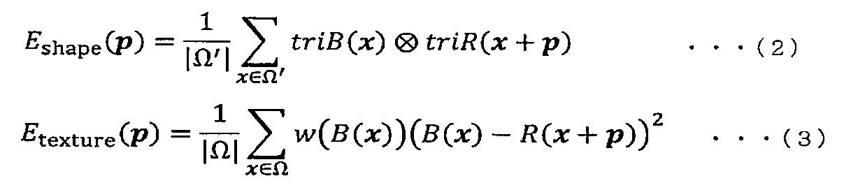
このコスト関数を用いたマッチング処理を採用することで、形状差異と模様差異の双方を考慮した処理を行うことができる。
また、重みαを調整することで、形状差異と模様差異の何れをより重要視するかを調整できる。α=0とすれば形状差異のみを用いたマッチングとなり、α=1とすれば形状差異と模様差異の重視度がバランスさせたマッチングとなり、αを大きくすることで模様差異をより重視する。
例えば、複数の入力画像間の明るさの差異が大きい場合、模様の一致が難しいので形状差異を重視したα(小さな値)を採用し、そうでない場合は模様差異も考慮したα(大きな値)を採用することが望ましい。
なお、コスト関数(1)の数式表記は一例である。また、数式上の各変数の位置(αの位置など)は、上記例に限定するものではない。
或いは、コスト関数(1)の変形例として、各輝度領域形状の変位pに関する滑らかさ項を導入してもよい。より具体的には、例えば、下記で示す式(4)のように、各輝度領域形状の変位が同等であればあるほど小さな値になるように滑らかさ項を設計すればよい。
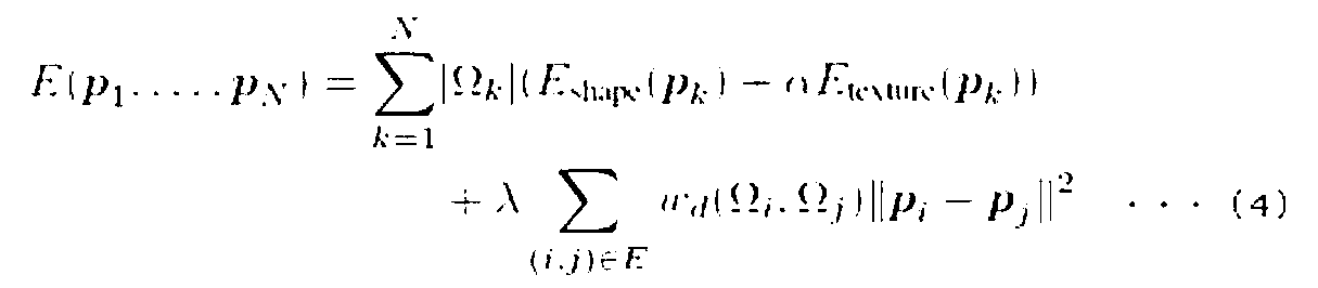
なお、式(4)を最適化する方法としては、例えば、以下のような繰り返し処理をすればよい。まず、輝度領域形状毎に式(1)を用いて独立に変位pを算出する。次に、任意に選択したある輝度領域形状(例えばj)以外の変位については、その値を固定し、選択した輝度領域形状の変位のみを、式(4)を用いて決定するという処理を、複数回繰り返す。繰り返し処理によって、式(4)の値の変化が十分に小さくなった場合、繰り返し処理を終了し、得られた変位pを式(4)の近似最適解とする。
次に、入力画像の生成処理例と各領域の補完処理例を説明する。
図10は、一実施例の全体の処理動作を示したフローチャートである。
図11は、一実施例の暗部領域を補完する処理動作を示したフローチャートである。
図12は、一実施例の明部領域を補完する処理動作を示したフローチャートである。
図10に示すように、HDR画像合成システム(情報処理装置)は、異なる輝度成分を有する複数の画像を受け付けて、入力画像として調整する(S1001)。この際、画像群の輝度的順序に従った並び替えを行う。単純には、各画像の撮像時の露出時間順に並び替えて1からnまでナンバリングすればよい。また、画像解析によって、平均明度などから順序付けてもよい。次に、先に説明した画像間の輝度成分関係が成立する各閾値をナンバリングした画像間で確定する。
(入力画像は、各々の画像内の輝度成分の明るすぎる領域と適切な明るさ領域の境界輝度が輝度的に隣接関係にあるより暗い画像の適切な明るさ領域と暗すぎる領域の境界輝度に揃う輝度成分関係を有する。)
図10中に示した5つの画像は、露出が異なる画像を複数のカメラで撮像した入力画像である。この画像群を並び替えると、露出時間の長い順で、画像3→画像5→画像1→画像2→画像4の順序になる。なお、家の位置が画像毎に異なる位置に描写されている。
次に、HDR画像合成システムは、入力画像の各画像の三値化画像をそれぞれ生成する(S1002)。この三値画像化で各々の画像の“明るすぎる領域”、“適切な明るさ領域”、“暗すぎる領域”が定まる。各領域を“明るすぎる領域マスク”、“適切な明るさ領域マスク”、“暗すぎる領域マスク”として設定する。各マスクは、元画像に重ねて、変更しない領域を示す情報である。
次に、HDR画像合成システムは、適度な輝度領域量を参照したり、家部分指定などを受け付けて、入力画像から基準画像を選出する(S1003)。
この際、基準画像の“適切な明るさ領域マスク”でマスクされなかった領域(“明るすぎる領域マスク”と“暗すぎる領域マスク”の領域)がそれぞれ補完領域に選出される。
換言すれば、基準画像の“適切な明るさ領域”に該当しなかった領域(“明るすぎる領域”と“暗すぎる領域”)がそれぞれ補完領域として選出される。
本処理例では、画像1を基準画像として選択したことと想定する。
次に、HDR画像合成システムは、基準画像の“明るすぎる領域マスク”と“暗すぎる領域マスク”の領域を各参照画像内でマッチングした各マスク領域の画像を用いて逐次的に補完する(S1004)、(S1005)。本処理は、図11及び図12を用いて詳説する。
この処理過程で実施される基準画像と参照画像群との間でマッチングする領域の探索処理によって、画像間に現れていた被写体の位置ずれ(本例の家の位置)や、カメラの違いなどの異なる撮像因子を吸収する。
最後に、HDR画像合成システムは、領域毎に輝度調整した合成画像を生成してHDR画像として出力する(S1006)。
次に、基準画像の暗部領域を補完する処理動作例を図11を用いて説明する。本処理は、図10のS1004である。
まず、HDR画像合成システム(画像合成部)は、基準画像を“n”と置き、マッチングを図る参照画像を“m=1”と置き、基準画像と対比する参照画像を1画像選択する(S2001)。ここで“n”は、先にナンバリングした番号(本例では“No.3”)であり、選択される参照画像は“No.2”である。次のターンで参照画像は“No.1”が選択される。図11中に基準画像No.3(img1)と参照画像No.1(img3)と参照画像No.2(img5)を示す。
次に、HDR画像合成システムは、選択した参照画像の各マスクを識別して“暗すぎる領域マスク”の領域と“適切な明るさ領域マスク”とを組み合わせた参照マスクを生成する(S2002)。本処理によって、図中の家の屋根部分(適切な明るさ領域マスク)と家の壁面(暗すぎる領域マスク)が合わさった家の屋根と壁面(参照マスク)が多値画像の各領域形状を基準に識別される。なお、画像中に多数の領域があれば適宜組み合わせて用いる。また、離れた各領域は別々に扱い、近場の各領域は1グループの領域として扱うことが望ましい。
次に、HDR画像合成システムは、基準画像の“暗すぎる領域マスク”と生成した“参照マスク”、必要に応じて参照画像の個々の“適切な明るさ領域マスク”を対比して、マッチングする領域を探索する(S2003)。この際、模様を踏まえてマッチングするとロバスト性が向上する。
本処理によって、基準画像の家の屋根と壁面(暗すぎる領域マスク)と参照画像の家の屋根と壁面(参照マスク)がマッチングする。
なお、3値化以上の多値化画像を用いることで、輝度的境界部分に曖昧性を持たせることができ、マッチング精度が向上する。
次に、HDR画像合成システムは、マッチングした基準画像の“暗すぎる領域”に、このターンの参照画像の“参照マスク”や、参照画像の個々の“適切な明るさ領域マスク”のテクスチャを用いて上書き若しくは合成して、基準画像を更新する(S2004)。
本処理によって、基準画像の家の屋根と壁面(暗すぎる領域マスク)が参照画像の家の屋根と壁面(参照マスク)で上書き若しくは合成される。
次に、HDR画像合成システムは、更新した基準画像に“暗すぎる領域”が無い若しくは“m”が採り得る最大値であれば暗部領域を補完する処理を終了し、利用する参照画像が残っていれば、S2001に戻り次の参照画像を選択する(S2005)。
次のターンによって、No.1画像の壁面(参照マスク)が基準画像に取り込まれる。
結果、位置描写が異なる1ないし複数の画像(参照画像)を用いて、基準画像の補正画像内で“暗すぎる領域”にあたる元画像の画像部分を、参照画像内でマッチングした領域で且つ各々の参照画像内で“適度な明るさ領域”にあたる画像部分を用いて補完処理できる。
次に、基準画像の明部領域を補完する処理動作例を図12を用いて説明する。本処理は、図10のS1005である。
まず、HDR画像合成システム(画像合成部)は、基準画像を“n”と置き、マッチングを図る参照画像を“m=1”と置き、基準画像と対比する参照画像を1画像選択する(S3001)。ここで“n”は、先にナンバリングした番号(本例では“No.3”)であり、選択される参照画像は“No.4”である。次のターンで参照画像は“No.5”が選択される。図12中に基準画像No.3(img1)と参照画像No.4(img2)と参照画像No.5(img4)を示す。
次に、HDR画像合成システムは、選択した参照画像の各マスクを識別して“明るすぎる領域マスク”の領域と“適切な明るさ領域マスク”とを組み合わせた参照マスクを生成する(S3002)。本処理によって、図中の太陽(明るすぎる領域マスク)と外延部分(適切な明るさ領域マスク)が合わさった太陽の周囲(参照マスク)が多値画像の各領域形状を基準に識別される。なお、画像中に多数の領域があれば適宜組み合わせて用いる。また、離れた各領域は別々に扱い、近場の各領域は1グループの領域として扱うことが望ましい。
次に、HDR画像合成システムは、基準画像の“明るすぎる領域マスク”と生成した“参照マスク”、必要に応じて参照画像の個々の“適切な明るさ領域マスク”を対比して、マッチングする領域を探索する(S3003)。この際、模様を踏まえてマッチングすると精度が向上する。
本処理によって、基準画像の太陽の周囲(明るすぎる領域マスク)と参照画像の太陽の周囲(参照マスク)がマッチングする。
なお、3値化以上の多値化画像を用いることで、輝度的境界部分に曖昧性を持たせることができ、マッチングのロバスト性が向上する。
次に、HDR画像合成システムは、マッチングした基準画像の“明るすぎる領域”に、このターンの参照画像の“参照マスク”や、参照画像の個々の“適切な明るさ領域マスク”のテクスチャを用いて上書き若しくは合成して、基準画像を更新する(S3004)。
本処理によって、基準画像の太陽の周囲(暗すぎる領域マスク)が参照画像の家の屋根と壁面(参照マスク)で上書き若しくは合成される。
次に、HDR画像合成システムは、更新した基準画像に“明るすぎる領域”が無い若しくは“m”が採り得る最大値であれば明部領域を補完する処理を終了し、利用する参照画像が残っていれば、S3001に戻り次の参照画像を選択する(S3005)。
次のターンによって、No.5画像の太陽内面(参照マスク)が基準画像に取り込まれる。
結果、位置描写が異なる1ないし複数の画像(参照画像)を用いて、基準画像の補正画像内で“明すぎる領域”にあたる元画像の画像部分を、参照画像内でマッチングした領域で且つ各々の参照画像内で“適度な明るさ領域”にあたる画像部分を用いて補完処理できる。
上記例示した基準画像の補正画像内で明るすぎる領域と暗すぎる領域にあたる画像部分を、参照画像内でマッチングした領域で且つ各々の参照画像内で適度な明るさ領域にあたる画像部分を用いて補完処理することで、HDR画像合成システムは、図13に示したようなHDR画像を生成できる。
以上説明したように、本画像処理システムによれば、輝度的関係に特徴を有する複数の画像を入力として、撮像位置や時間などの撮像因子が異なっていても、所望するようにハイダイナミックレンジ画像を得られうる。
これは、基準画像の要補完領域に合致する参照画像の一部を探索し、探索結果の部分画像を用いて基準画像の要補完領域を参照画像内の適切な明るさ領域の画像を用いて補完する処理行うためである。
なお、画像処理システムの各部は、ハードウェアとソフトウェアの組み合わせを用いて実現すればよい。ハードウェアとソフトウェアとを組み合わせた形態では、図14に示すように、RAM(Random Access Memory)に画像処理プログラムが展開され、該プログラムに基づいて制御部(CPU(Central Processing Unit))等のハードウェアを動作させることによって、画像受付部、基準画像選定部、補完領域探索部、補完処理部、出力部の全て又は一部の手段として機能させる。また、このプログラムは、記録媒体に固定的に記録されて頒布されても良い。当該記録媒体に記録されたプログラムは、有線、無線、又は記録媒体そのものを介して、メモリに読込まれ、制御部等を動作させる。尚、記録媒体を例示すれば、オプティカルディスクや磁気ディスク、半導体メモリ装置、ハードディスクなどが挙げられる。また、各部の全て又は一部をLSI上に回路構築して形成してもよい。
本発明の具体的な構成は前述の実施形態に限られるものではなく、ブロック構成の分離併合、手順の入れ替え、各実施形態の組み合わせなど、この発明の要旨を逸脱しない範囲の変更があってもこの発明に含まれる。
また、上記の実施形態の一部又は全部は、以下のようにも記載されうる。尚、以下の付記は本発明をなんら限定するものではない。
[付記1]
異なる輝度成分を有する複数の画像を入力画像として受け付ける画像受付部と、
前記複数の画像内から基準画像を選定する基準画像選定部と、
前記複数の画像内の他の画像を参照画像として用いて前記基準画像内の明るすぎる領域及び/又は暗すぎる領域を補完する部分画像を前記参照画像から抽出する際に、前記入力画像各々を輝度成分の区分毎に多値化処理した補正画像を用いて、前記基準画像の補正画像に含まれていた区分可能な各領域の形と前記他の画像の補正画像に含まれていた区分可能な各領域の形とを用いて、形状がマッチングする領域を探索処理する補完領域探索部と、
前記基準画像の補正画像内で明るすぎる領域及び/又は暗すぎる領域にあたる画像部分を、前記参照画像内でマッチングした領域で且つ各々の参照画像内で適度な明るさ領域にあたる画像部分を用いて補完処理することにより、合成画像を生成する補完処理部と、
生成した前記合成画像を出力する出力部を有し、
前記入力画像として、各々の画像は、明るい領域、適度な明るさ領域、暗い領域の少なくとも3値に区分可能であり、且つ、各々の画像内の輝度成分の明るい領域と適度な明るさ領域の境界輝度が輝度的に隣接関係にあるより暗い画像の適度な明るさ領域と暗い領域の境界輝度に揃う輝度成分関係を有した画像群を用いる
ことを特徴とする画像処理システム。
[付記2]
前記基準画像選定部は、基準画像を選定する際に、各々の画像が有する全面もしくは所定範囲の適度な明るさ領域の面積に基づいて、1ないし複数の面積が広い上位の画像を基準画像として選定処理することを特徴とする上記付記記載の画像処理システム。
[付記3]
前記補完領域探索部は、探索処理する際に、明るい領域、適度な明るさ領域、暗い領域を示す3区分に分類された前記補正画像を用いて、
前記基準画像の補正画像に含まれていた明るすぎる領域及び/又は暗すぎる領域の形を基準に、輝度的に隣接関係にある画像の補正画像に含まれていた適度な明るさ領域を含む区分可能な各領域の形をマッチング処理して、補完に使用する参照画像内の部分画像を前記参照画像から抽出する
ことを特徴とする上記付記記載の画像処理システム。
[付記4]
複数の参照画像を用いて前記探索処理と前記補完処理を繰り返し実行する際に、基準画像に輝度的に隣接関係にある参照画像を用いて基準画像を補完した後に、次に輝度的に隣接関係にある参照画像を用いて補完された基準画像を更に補完するように基準画像の明るすぎる領域及び/又は暗すぎる領域を埋めながら繰り返すことを特徴とする上記付記記載の画像処理システム。
[付記5]
複数の参照画像を用いて前記探索処理と前記補完処理を繰り返し実行する際に、基準画像に輝度的に最も遠い関係にある参照画像を用いて基準画像を補完した後に、次に輝度的に最も遠い関係にある参照画像を用いて補完された基準画像を更に補完するように基準画像の明るすぎる領域及び/又は暗すぎる領域を埋めながら繰り返すことを特徴とする上記付記記載の画像処理システム。
[付記6]
複数の参照画像を用いて前記探索処理と前記補完処理を繰り返し実行する際に、輝度的に隣接関係にある参照画像相互の探索処理によって、各参照画像内に有る明るすぎる領域及び/又は暗すぎる領域を他の参照画像を用いて補完した後に、基準画像に輝度的に隣接関係にある参照画像を用いて基準画像を補完することを特徴とする上記付記記載の画像処理システム。
[付記7]
前記補完処理では、基準画像を参照画像を用いて補完した領域内で、補完に用いた参照画像の補正画像内で明るすぎる領域及び/又は暗すぎる領域にあたる画像部分を、残りの参照画像を用いてマッチングできた領域を用いて補完することを特徴とする上記付記記載の画像処理システム。
[付記8]
複数の参照画像を用いて前記探索処理と前記補完処理を繰り返し実行する際に、選定された基準画像内で補完を要する明るすぎる領域及び/又は暗すぎる領域にあたる画像部分を、前記基準画像に輝度的に近い参照画像からより遠い参照画像を順番に用いる順に、明るすぎる領域及び/又は暗すぎる領域を埋める参照画像に分けて繰り返すことを特徴とする上記付記記載の画像処理システム。
[付記9]
各参照画像から取得した領域毎の各部分画像に輝度調整処理を加え、
輝度調整された各領域の各部分画像を前記基準画像の明るすぎる領域及び/又は暗すぎる領域にあたる画像部分に適切な明るさ領域部分の輝度調整をした後に補完する
ことを特徴とする上記付記記載の画像処理システム。
[付記10]
参照画像内で基準画像にマッチングした領域で且つ各々の参照画像内で適切な明るさ領域にあたる画像部分の画像内容を参照して、残りの全て若しくは一部の参照画像とマッチングする領域を探索することを特徴とする上記付記記載の画像処理システム。
[付記11]
参照画像と基準画像とのマッチング領域を探索する際に、下記に示すコスト関数(1)を満たして、参照画像内のマッチングする領域を探索することを特徴とする上記付記記載の画像処理システム。

EΩ(p)は個々の輝度領域形状のマッチング総コスト、
Eshape(p)は排他的論理和で探索するコスト関数部分、
Etexture(p)は重み付きSSDで探索するコスト関数部分、
αは重み変数である。
[付記12]
参照画像と基準画像とのマッチング領域を探索する際に、下記に示すコスト関数(4)を満たして、参照画像内のマッチングする領域を探索することを特徴とする上記付記記載の画像処理システム。

EΩ(p1,・・・,pN)は、各輝度領域形状のペアの全ての組み合わせの総コスト、
Eshape(pk)は排他的論理和で探索するコスト関数部分、
Etexture(pk)は重み付きSSDで探索するコスト関数部分、
αは重み変数、
λは各輝度領域形状の変位pに関する滑らかさ項の大きさ、
ωd(Ωi,Ωj)は輝度領域形状iと輝度領域形状jの滑らかさ項の強さを示す重みである。
[付記13]
前記探索処理では、輝度成分の区分が同一である所定近似関係にある複数の抽出領域を1ないし複数のグループとして扱うことを特徴とする上記付記記載の画像処理システム。
[付記14]
複数の画像を受け付けて、前記入力画像を受け付けて、前記入力画像が有する画像間の輝度成分関係を満たすように、輝度的順序に従った並び替えと、前記輝度成分関係が成立する各閾値を画像間で確定することを特徴とする上記付記記載の画像処理システム。
[付記15]
異なる輝度成分を有する複数の画像を入力画像として受け付けて、
前記複数の画像内から基準画像を選定すると共に、
前記複数の画像内の他の画像を参照画像として用いて前記基準画像内の明るすぎる領域及び/又は暗すぎる領域を補完する部分画像を前記参照画像から抽出する際に、前記入力画像各々を輝度成分の区分毎に多値化処理した補正画像を用いて、前記基準画像の補正画像に含まれていた区分可能な各領域の形と前記他の画像の補正画像に含まれていた区分可能な各領域の形とを用いて、形状がマッチングする領域を探索処理し、
前記基準画像の補正画像内で明るすぎる領域及び/又は暗すぎる領域にあたる画像部分を、前記参照画像内でマッチングした領域で且つ各々の参照画像内で適切な明るさ領域にあたる画像部分を用いて補完処理して、合成画像を生成する、
ただし、前記入力画像として、各々の画像は、明るすぎる領域、適切な明るさ領域、暗すぎる領域の少なくとも3値に区分可能であり、且つ、各々の画像内の輝度成分の明るすぎる領域と適切な明るさ領域の境界輝度が輝度的に隣接関係にあるより暗い画像の適切な明るさ領域と暗すぎる領域の境界輝度に揃う輝度成分関係を有した画像群を用いる
ことを特徴とする情報処理システムによる画像処理方法。
[付記16]
前記情報処理システムは、基準画像を選定する際に、各々の画像が有する全面もしくは所定範囲の適度な明るさ領域の面積に基づいて、1ないし複数の面積が広い上位の画像を基準画像として選定処理することを特徴とする上記付記記載の画像処理方法。
[付記17]
前記情報処理システムは、探索処理する際に、明るい領域、適度な明るさ領域、暗い領域を示す3区分に分類された前記補正画像を用いて、
前記基準画像の補正画像に含まれていた明るすぎる領域及び/又は暗すぎる領域の形を基準に、輝度的に隣接関係にある画像の補正画像に含まれていた適度な明るさ領域を含む区分可能な各領域の形をマッチング処理して、補完に使用する参照画像内の部分画像を前記参照画像から抽出する
ことを特徴とする上記付記記載の画像処理方法。
[付記18]
前記情報処理システムは、複数の参照画像を用いて前記探索処理と前記補完処理を繰り返し実行する際に、基準画像に輝度的に隣接関係にある参照画像を用いて基準画像を補完した後に、次に輝度的に隣接関係にある参照画像を用いて補完された基準画像を更に補完するように基準画像の明るすぎる領域及び/又は暗すぎる領域を埋めながら繰り返すことを特徴とする上記付記記載の画像処理方法。
[付記19]
前記情報処理システムは、複数の参照画像を用いて前記探索処理と前記補完処理を繰り返し実行する際に、基準画像に輝度的に最も遠い関係にある参照画像を用いて基準画像を補完した後に、次に輝度的に最も遠い関係にある参照画像を用いて補完された基準画像を更に補完するように基準画像の明るすぎる領域及び/又は暗すぎる領域を埋めながら繰り返すことを特徴とする上記付記記載の画像処理方法。
[付記20]
前記情報処理システムは、複数の参照画像を用いて前記探索処理と前記補完処理を繰り返し実行する際に、輝度的に隣接関係にある参照画像相互の探索処理によって、各参照画像内に有る明るすぎる領域及び/又は暗すぎる領域を他の参照画像を用いて補完した後に、基準画像に輝度的に隣接関係にある参照画像を用いて基準画像を補完することを特徴とする上記付記記載の画像処理方法。
[付記21]
前記情報処理システムは、前記補完処理で、基準画像を参照画像を用いて補完した領域内で、補完に用いた参照画像の補正画像内で明るすぎる領域及び/又は暗すぎる領域にあたる画像部分を、残りの参照画像を用いてマッチングできた領域を用いて補完することを特徴とする上記付記記載の画像処理方法。
[付記22]
前記情報処理システムは、複数の参照画像を用いて前記探索処理と前記補完処理を繰り返し実行する際に、選定された基準画像内で補完を要する明るすぎる領域及び/又は暗すぎる領域にあたる画像部分を、前記基準画像に輝度的に近い参照画像からより遠い参照画像を順番に用いる順に、明るすぎる領域及び/又は暗すぎる領域を埋める参照画像に分けて繰り返すことを特徴とする上記付記記載の画像処理方法。
[付記23]
前記情報処理システムは、
各参照画像から取得した領域毎の各部分画像に輝度調整処理を加え、
輝度調整された各領域の各部分画像を前記基準画像の明るすぎる領域及び/又は暗すぎる領域にあたる画像部分に適切な明るさ領域部分の輝度調整をした後に補完することを特徴とする上記付記記載の画像処理方法。
[付記24]
前記情報処理システムは、参照画像内で基準画像にマッチングした領域で且つ各々の参照画像内で適切な明るさ領域にあたる画像部分の画像内容を参照して、残りの全て若しくは一部の参照画像とマッチングする領域を探索することを特徴とする上記付記記載の画像処理方法。
[付記25]
前記情報処理システムは、参照画像と基準画像とのマッチング領域を探索する際に、下記に示すコスト関数(1)を満たして、参照画像内のマッチングする領域を探索することを特徴とする上記付記記載の画像処理方法。

EΩ(p)は個々の輝度領域形状のマッチング総コスト、
Eshape(p)は排他的論理和で探索するコスト関数部分、
Etexture(p)は重み付きSSDで探索するコスト関数部分、
αは重み変数である。
[付記26]
前記情報処理システムは、参照画像と基準画像とのマッチング領域を探索する際に、下記に示すコスト関数(4)を満たして、参照画像内のマッチングする領域を探索することを特徴とする上記付記記載の画像処理方法。

EΩ(p1,・・・,pN)は、各輝度領域形状のペアの全ての組み合わせの総コスト、
Eshape(pk)は排他的論理和で探索するコスト関数部分、
Etexture(pk)は重み付きSSDで探索するコスト関数部分、
αは重み変数、
λは各輝度領域形状の変位pに関する滑らかさ項の大きさ、
ωd(Ωi,Ωj)は輝度領域形状iと輝度領域形状jの滑らかさ項の強さを示す重みである。
[付記27]
前記情報処理システムは、前記探索処理では、輝度成分の区分が同一である所定近似関係にある複数の抽出領域を1ないし複数のグループとして扱うことを特徴とする上記付記記載の画像処理方法。
[付記28]
前記情報処理システムは、複数の画像を受け付けて、前記入力画像を受け付けて、前記入力画像が有する画像間の輝度成分関係を満たすように、輝度的順序に従った並び替えと、前記輝度成分関係が成立する各閾値を画像間で確定することを特徴とする上記付記記載の画像処理方法。
[付記29]
情報処理システムを、
異なる輝度成分を有する複数の画像を入力画像として受け付ける画像受付部と、
前記複数の画像内から基準画像を選定する基準画像選定部と、
前記複数の画像内の他の画像を参照画像として用いて前記基準画像内の明るすぎる領域及び/又は暗すぎる領域を補完する部分画像を前記参照画像から抽出する際に、前記入力画像各々を輝度成分の区分毎に多値化処理した補正画像を用いて、前記基準画像の補正画像に含まれていた区分可能な各領域の形と前記他の画像の補正画像に含まれていた区分可能な各領域の形とを用いて、形状がマッチングする領域を探索処理する補完領域探索部と、
前記基準画像の補正画像内で明るすぎる領域及び/又は暗すぎる領域にあたる画像部分を、前記参照画像内でマッチングした領域で且つ各々の参照画像内で適度な明るさ領域にあたる画像部分を用いて補完処理することにより、合成画像を生成する補完処理部と、
生成した前記合成画像を出力する出力部として動作させることを特徴とするプログラム。
前記入力画像の条件として、各々の画像は、明るい領域、適度な明るさ領域、暗い領域の少なくとも3値に区分可能であり、且つ、各々の画像内の輝度成分の明るい領域と適度な明るさ領域の境界輝度が輝度的に隣接関係にあるより暗い画像の適度な明るさ領域と暗い領域の境界輝度に揃う輝度成分関係を有した画像群を用いる。
[付記30]
前記基準画像選定部を、基準画像を選定する際に、各々の画像が有する全面もしくは所定範囲の適度な明るさ領域の面積に基づいて、1ないし複数の面積が広い上位の画像を基準画像として選定処理するように動作させることを特徴とする上記付記記載のプログラム。
[付記31]
前記補完領域探索部を、探索処理する際に、明るい領域、適度な明るさ領域、暗い領域を示す3区分に分類された前記補正画像を用いて、
前記基準画像の補正画像に含まれていた明るすぎる領域及び/又は暗すぎる領域の形を基準に、輝度的に隣接関係にある画像の補正画像に含まれていた適度な明るさ領域を含む区分可能な各領域の形をマッチング処理して、補完に使用する参照画像内の部分画像を前記参照画像から抽出するように動作させる
ことを特徴とする上記付記記載のプログラム。
[付記32]
複数の参照画像を用いて前記探索処理と前記補完処理を繰り返し実行する際に、基準画像に輝度的に隣接関係にある参照画像を用いて基準画像を補完した後に、次に輝度的に隣接関係にある参照画像を用いて補完された基準画像を更に補完するように基準画像の明るすぎる領域及び/又は暗すぎる領域を埋めながら繰り返すように動作させることを特徴とする上記付記記載のプログラム。
[付記33]
複数の参照画像を用いて前記探索処理と前記補完処理を繰り返し実行する際に、基準画像に輝度的に最も遠い関係にある参照画像を用いて基準画像を補完した後に、次に輝度的に最も遠い関係にある参照画像を用いて補完された基準画像を更に補完するように基準画像の明るすぎる領域及び/又は暗すぎる領域を埋めながら繰り返すように動作させることを特徴とする上記付記記載のプログラム。
[付記34]
複数の参照画像を用いて前記探索処理と前記補完処理を繰り返し実行する際に、輝度的に隣接関係にある参照画像相互の探索処理によって、各参照画像内に有る明るすぎる領域及び/又は暗すぎる領域を他の参照画像を用いて補完した後に、基準画像に輝度的に隣接関係にある参照画像を用いて基準画像を補完するように動作させることを特徴とする上記付記記載のプログラム。
[付記35]
前記補完処理では、基準画像を参照画像を用いて補完した領域内で、補完に用いた参照画像の補正画像内で明るすぎる領域及び/又は暗すぎる領域にあたる画像部分を、残りの参照画像を用いてマッチングできた領域を用いて補完するように動作させることを特徴とする上記付記記載のプログラム。
[付記36]
複数の参照画像を用いて前記探索処理と前記補完処理を繰り返し実行する際に、選定された基準画像内で補完を要する明るすぎる領域及び/又は暗すぎる領域にあたる画像部分を、前記基準画像に輝度的に近い参照画像からより遠い参照画像を順番に用いる順に、明るすぎる領域及び/又は暗すぎる領域を埋める参照画像に分けて繰り返すように動作させることを特徴とする上記付記記載のプログラム。
[付記37]
各参照画像から取得した領域毎の各部分画像に輝度調整処理を加え、
輝度調整された各領域の各部分画像を前記基準画像の明るすぎる領域及び/又は暗すぎる領域にあたる画像部分に適切な明るさ領域部分の輝度調整をした後に補完するように動作させることを特徴とする上記付記記載のプログラム。
[付記38]
参照画像内で基準画像にマッチングした領域で且つ各々の参照画像内で適切な明るさ領域にあたる画像部分の画像内容を参照して、残りの全て若しくは一部の参照画像とマッチングする領域を探索するように動作させることを特徴とする上記付記記載のプログラム。
[付記39]
参照画像と基準画像とのマッチング領域を探索する際に、下記に示すコスト関数(1)を満たして、参照画像内のマッチングする領域を探索するように動作させることを特徴とする上記付記記載のプログラム。

EΩ(p)は個々の輝度領域形状のマッチング総コスト、
Eshape(p)は排他的論理和で探索するコスト関数部分、
Etexture(p)は重み付きSSDで探索するコスト関数部分、
αは重み変数である。
[付記40]
参照画像と基準画像とのマッチング領域を探索する際に、下記に示すコスト関数(4)を満たして、参照画像内のマッチングする領域を探索するように動作させることを特徴とする上記付記記載の画像処理プログラム。

EΩ(p1,・・・,pN)は、各輝度領域形状のペアの全ての組み合わせの総コスト、
Eshape(pk)は排他的論理和で探索するコスト関数部分、
Etexture(pk)は重み付きSSDで探索するコスト関数部分、
αは重み変数、
λは各輝度領域形状の変位pに関する滑らかさ項の大きさ、
ωd(Ωi,Ωj)は輝度領域形状iと輝度領域形状jの滑らかさ項の強さを示す重みである。
[付記41]
前記探索処理では、輝度成分の区分が同一である所定近似関係にある複数の抽出領域を1ないし複数のグループとして扱うことように動作させることを特徴とする上記付記記載のプログラム。
[付記42]
複数の画像を受け付けて、前記入力画像を受け付けて、前記入力画像が有する画像間の輝度成分関係を満たすように、輝度的順序に従った並び替えと、前記輝度成分関係が成立する各閾値を画像間で確定するように動作させることを特徴とする上記付記記載のプログラム。
[付記43]
上記付記に記載のプログラムを非一時的に記録したコンピュータ読み取り可能な記録媒体。
この出願は、2013年11月14日に出願された日本出願特願2013−235787号を基礎とする優先権を主張し、その開示の全てをここに取り込む。
10 画像受付部(画像受付手段)
20 基準画像選定部(基準画像選定手段)
30 補完領域探索部(補完領域探索手段)
40 補完処理部(補完処理手段)
50 出力部(出力手段)
Claims (10)
- 異なる輝度成分を有する複数の画像を入力画像として受け付ける画像受付部と、
前記複数の画像内から基準画像を選定する基準画像選定部と、
前記複数の画像内の他の画像を参照画像として用いて前記基準画像内の明るすぎる領域及び/又は暗すぎる領域を補完する部分画像を前記参照画像から抽出する際に、前記入力画像各々を輝度成分の区分毎に多値化処理した補正画像を用いて、前記基準画像の補正画像に含まれていた区分可能な各領域の形と前記他の画像の補正画像に含まれていた区分可能な各領域の形とを用いて、形状がマッチングする領域を探索処理する補完領域探索部と、
前記基準画像の補正画像内で明るすぎる領域及び/又は暗すぎる領域にあたる画像部分を、前記参照画像内でマッチングした領域で且つ各々の参照画像内で適度な明るさ領域にあたる画像部分を用いて補完処理することにより、合成画像を生成する補完処理部と、
生成した前記合成画像を出力する出力部を有し、
前記入力画像として、各々の画像は、明るい領域、適度な明るさ領域、暗い領域の少なくとも3値に区分可能であり、且つ、各々の画像内の輝度成分の明るい領域と適度な明るさ領域の境界輝度が輝度的に隣接関係にあるより暗い画像の適度な明るさ領域と暗い領域の境界輝度に揃う輝度成分関係を有した画像群を用いる
ことを特徴とする画像処理システム。 - 前記基準画像選定部は、基準画像を選定する際に、各々の画像が有する全面もしくは所定範囲の適度な明るさ領域の面積に基づいて、1ないし複数の面積が広い上位の画像を基準画像として選定処理することを特徴とする請求項1記載の画像処理システム。
- 前記補完領域探索部は、探索処理する際に、明るい領域、適度な明るさ領域、暗い領域を示す3区分に分類された前記補正画像を用いて、
前記基準画像の補正画像に含まれていた明るすぎる領域及び/又は暗すぎる領域の形を基準に、輝度的に隣接関係にある画像の補正画像に含まれていた適度な明るさ領域を含む区分可能な各領域の形をマッチング処理して、補完に使用する参照画像内の部分画像を前記参照画像から抽出する
ことを特徴とする請求項1又は2に記載の画像処理システム。 - 複数の参照画像を用いて前記探索処理と前記補完処理を繰り返し実行する際に、基準画像に輝度的に隣接関係にある参照画像を用いて基準画像を補完した後に、次に輝度的に隣接関係にある参照画像を用いて補完された基準画像を更に補完するように基準画像の明るすぎる領域及び/又は暗すぎる領域を埋めながら繰り返すことを特徴とする請求項1ないし3の何れか一項に記載の画像処理システム。
- 参照画像内で基準画像にマッチングした領域で且つ各々の参照画像内で適切な明るさ領域にあたる画像部分の画像内容を参照して、残りの全て若しくは一部の参照画像とマッチングする領域を探索することを特徴とする請求項1ないし4の何れか一項に記載の画像処理システム。
- 参照画像と基準画像とのマッチング領域を探索する際に、下記に示すコスト関数(1)を満たして、参照画像内のマッチングする領域を探索することを特徴とする請求項1ないし5の何れか一項に記載の画像処理システム。
ここで、
EΩ(p)は個々の輝度領域形状のマッチング総コスト、
Eshape(p)は排他的論理和で探索するコスト関数部分、
Etexture(p)は重み付きSSDで探索するコスト関数部分、
αは重み変数である。 - 前記探索処理では、輝度成分の区分が同一である所定近似関係にある複数の抽出領域を1ないし複数のグループとして扱うことを特徴とする請求項1ないし6の何れか一項に記載の画像処理システム。
- 複数の画像を受け付けて、前記入力画像を受け付けて、前記入力画像が有する画像間の輝度成分関係を満たすように、輝度的順序に従った並び替えと、前記輝度成分関係が成立する各閾値を画像間で確定することを特徴とする請求項1ないし7の何れか一項に記載の画像処理システム。
- 異なる輝度成分を有する複数の画像を入力画像として受け付けて、
前記複数の画像内から基準画像を選定すると共に、
前記複数の画像内の他の画像を参照画像として用いて前記基準画像内の明るすぎる領域及び/又は暗すぎる領域を補完する部分画像を前記参照画像から抽出する際に、前記入力画像各々を輝度成分の区分毎に多値化処理した補正画像を用いて、前記基準画像の補正画像に含まれていた区分可能な各領域の形と前記他の画像の補正画像に含まれていた区分可能な各領域の形とを用いて、形状がマッチングする領域を探索処理し、
前記基準画像の補正画像内で明るすぎる領域及び/又は暗すぎる領域にあたる画像部分を、前記参照画像内でマッチングした領域で且つ各々の参照画像内で適切な明るさ領域にあたる画像部分を用いて補完処理して、合成画像を生成する、
ただし、前記入力画像として、各々の画像は、明るすぎる領域、適切な明るさ領域、暗すぎる領域の少なくとも3値に区分可能であり、且つ、各々の画像内の輝度成分の明るすぎる領域と適切な明るさ領域の境界輝度が輝度的に隣接関係にあるより暗い画像の適切な明るさ領域と暗すぎる領域の境界輝度に揃う輝度成分関係を有した画像群を用いる
ことを特徴とする情報処理システムによる画像処理方法。 - 情報処理システムを、
異なる輝度成分を有する複数の画像を入力画像として受け付ける画像受付部と、
前記複数の画像内から基準画像を選定する基準画像選定部と、
前記複数の画像内の他の画像を参照画像として用いて前記基準画像内の明るすぎる領域及び/又は暗すぎる領域を補完する部分画像を前記参照画像から抽出する際に、前記入力画像各々を輝度成分の区分毎に多値化処理した補正画像を用いて、前記基準画像の補正画像に含まれていた区分可能な各領域の形と前記他の画像の補正画像に含まれていた区分可能な各領域の形とを用いて、形状がマッチングする領域を探索処理する補完領域探索部と、
前記基準画像の補正画像内で明るすぎる領域及び/又は暗すぎる領域にあたる画像部分を、前記参照画像内でマッチングした領域で且つ各々の参照画像内で適度な明るさ領域にあたる画像部分を用いて補完処理することにより、合成画像を生成する補完処理部と、
生成した前記合成画像を出力する出力部、
として動作させることを特徴とするプログラムを非一時的に記録したコンピュータ読み取り可能な記録媒体。
前記入力画像の条件として、各々の画像は、明るい領域、適度な明るさ領域、暗い領域の少なくとも3値に区分可能であり、且つ、各々の画像内の輝度成分の明るい領域と適度な明るさ領域の境界輝度が輝度的に隣接関係にあるより暗い画像の適度な明るさ領域と暗い領域の境界輝度に揃う輝度成分関係を有した画像群を用いる。
Priority Applications (2)
| Application Number | Priority Date | Filing Date | Title |
|---|---|---|---|
| JP2015547715A JP6557848B2 (ja) | 2013-11-14 | 2014-10-17 | 画像処理システム |
| US15/036,231 US9747675B2 (en) | 2013-11-14 | 2014-10-17 | Image processing system |
Applications Claiming Priority (2)
| Application Number | Priority Date | Filing Date | Title |
|---|---|---|---|
| JP2013235787 | 2013-11-14 | ||
| JP2013-235787 | 2013-11-14 |
Publications (1)
| Publication Number | Publication Date |
|---|---|
| WO2015072306A1 true WO2015072306A1 (ja) | 2015-05-21 |
Family
ID=53057246
Family Applications (1)
| Application Number | Title | Priority Date | Filing Date |
|---|---|---|---|
| PCT/JP2014/078282 Ceased WO2015072306A1 (ja) | 2013-11-14 | 2014-10-17 | 画像処理システム |
Country Status (3)
| Country | Link |
|---|---|
| US (1) | US9747675B2 (ja) |
| JP (1) | JP6557848B2 (ja) |
| WO (1) | WO2015072306A1 (ja) |
Cited By (2)
| Publication number | Priority date | Publication date | Assignee | Title |
|---|---|---|---|---|
| CN111565261A (zh) * | 2020-06-02 | 2020-08-21 | 厦门美图之家科技有限公司 | 图像处理方法、装置及电子设备 |
| US20210004941A1 (en) * | 2019-07-04 | 2021-01-07 | Apical Limited | Image data pre-processing for neural networks |
Families Citing this family (8)
| Publication number | Priority date | Publication date | Assignee | Title |
|---|---|---|---|---|
| CN106461928B (zh) * | 2014-06-10 | 2019-09-17 | 奥林巴斯株式会社 | 图像处理装置、摄像装置、显微镜系统以及图像处理方法 |
| KR20160067275A (ko) * | 2014-12-03 | 2016-06-14 | 삼성디스플레이 주식회사 | 표시 장치 및 이의 구동 방법 |
| JP6521776B2 (ja) * | 2015-07-13 | 2019-05-29 | オリンパス株式会社 | 画像処理装置、画像処理方法 |
| US20170332000A1 (en) * | 2016-05-10 | 2017-11-16 | Lytro, Inc. | High dynamic range light-field imaging |
| TWI764898B (zh) * | 2016-08-03 | 2022-05-21 | 日商新力股份有限公司 | 資訊處理裝置、資訊處理方法及程式 |
| JP6622156B2 (ja) * | 2016-08-24 | 2019-12-18 | 株式会社東芝 | 情報処理装置、情報処理方法およびプログラム |
| US11049224B2 (en) | 2018-12-05 | 2021-06-29 | Microsoft Technology Licensing, Llc | Automated real-time high dynamic range content review system |
| CN112258417B (zh) * | 2020-10-28 | 2023-02-28 | 杭州海康威视数字技术股份有限公司 | 一种图像生成方法、装置及设备 |
Citations (2)
| Publication number | Priority date | Publication date | Assignee | Title |
|---|---|---|---|---|
| JP2009010566A (ja) * | 2007-06-27 | 2009-01-15 | Yamaguchi Univ | 写真画像のダイナミックレンジを拡大する方法及び撮像装置 |
| JP2010272094A (ja) * | 2009-05-25 | 2010-12-02 | Olympus Corp | 画像取得装置、画像合成方法、及び顕微鏡システム |
Family Cites Families (6)
| Publication number | Priority date | Publication date | Assignee | Title |
|---|---|---|---|---|
| JP4732315B2 (ja) * | 2006-12-05 | 2011-07-27 | キヤノン株式会社 | 画像処理装置及び方法 |
| JP2008271418A (ja) * | 2007-04-24 | 2008-11-06 | Canon Inc | 画像形成装置 |
| JP5245648B2 (ja) | 2008-08-27 | 2013-07-24 | カシオ計算機株式会社 | 画像処理装置、及び、プログラム |
| JP2010278890A (ja) | 2009-05-29 | 2010-12-09 | Canon Inc | 画像形成装置、画像形成方法 |
| JP2013093786A (ja) | 2011-10-27 | 2013-05-16 | Seiko Epson Corp | 画像処理装置及び方法、並びに電子機器 |
| JP2013162190A (ja) * | 2012-02-02 | 2013-08-19 | Canon Inc | ハイダイナミックレンジ動画撮影補助装置 |
-
2014
- 2014-10-17 WO PCT/JP2014/078282 patent/WO2015072306A1/ja not_active Ceased
- 2014-10-17 JP JP2015547715A patent/JP6557848B2/ja active Active
- 2014-10-17 US US15/036,231 patent/US9747675B2/en active Active
Patent Citations (2)
| Publication number | Priority date | Publication date | Assignee | Title |
|---|---|---|---|---|
| JP2009010566A (ja) * | 2007-06-27 | 2009-01-15 | Yamaguchi Univ | 写真画像のダイナミックレンジを拡大する方法及び撮像装置 |
| JP2010272094A (ja) * | 2009-05-25 | 2010-12-02 | Olympus Corp | 画像取得装置、画像合成方法、及び顕微鏡システム |
Cited By (4)
| Publication number | Priority date | Publication date | Assignee | Title |
|---|---|---|---|---|
| US20210004941A1 (en) * | 2019-07-04 | 2021-01-07 | Apical Limited | Image data pre-processing for neural networks |
| US11816813B2 (en) * | 2019-07-04 | 2023-11-14 | Arm Limited | Image data pre-processing for neural networks |
| CN111565261A (zh) * | 2020-06-02 | 2020-08-21 | 厦门美图之家科技有限公司 | 图像处理方法、装置及电子设备 |
| CN111565261B (zh) * | 2020-06-02 | 2022-05-31 | 厦门美图之家科技有限公司 | 图像处理方法、装置及电子设备 |
Also Published As
| Publication number | Publication date |
|---|---|
| JP6557848B2 (ja) | 2019-08-14 |
| JPWO2015072306A1 (ja) | 2017-03-16 |
| US20160292835A1 (en) | 2016-10-06 |
| US9747675B2 (en) | 2017-08-29 |
Similar Documents
| Publication | Publication Date | Title |
|---|---|---|
| JP6557848B2 (ja) | 画像処理システム | |
| KR101643607B1 (ko) | 영상 데이터 생성 방법 및 장치 | |
| US10666873B2 (en) | Exposure-related intensity transformation | |
| US11546567B2 (en) | Multimodal foreground background segmentation | |
| JP6730690B2 (ja) | シーン内に存在する不要なオブジェクトの除去に基づくシーンの画像の動的生成 | |
| US9305372B2 (en) | Method and device for image processing | |
| Shan et al. | The visual turing test for scene reconstruction | |
| US8817015B2 (en) | Methods, apparatus, and computer-readable storage media for depth-based rendering of focused plenoptic camera data | |
| Ballabeni et al. | Advances in image pre-processing to improve automated 3D reconstruction | |
| US9679223B2 (en) | Image processing method and apparatus | |
| US20110182528A1 (en) | Method and device for generating images having a reduced error rate, high resolution and improved contrast | |
| US20140340486A1 (en) | Image processing system, image processing method, and image processing program | |
| JPWO2017159312A1 (ja) | 画像処理装置、撮像装置、および画像処理方法、並びにプログラム | |
| CN106447607B (zh) | 一种图像拼接方法及装置 | |
| US9165341B2 (en) | Method for generating super-resolution images having improved image resolution and measuring device | |
| US12456223B2 (en) | System and method for maximizing inference accuracy using recaptured datasets | |
| KR101893191B1 (ko) | 주요 색상을 이용하는 영상 분석 장치 및 그 제어 방법 | |
| Schreiberhuber et al. | Gigadepth: Learning depth from structured light with branching neural networks | |
| JP6478639B2 (ja) | 画像処理装置、画像処理方法、及びプログラム | |
| Sarode et al. | Image super resolution using enhanced super resolution generative adversarial network | |
| Boss et al. | Single image brdf parameter estimation with a conditional adversarial network | |
| US20140368701A1 (en) | Cloning image data patch in hole of pixel array (patch and clone) | |
| WO2016116666A1 (en) | Image processing method for movement detection and compensation | |
| JP6120632B2 (ja) | 画像処理装置、画像処理方法、及び画像処理プログラム | |
| Lin et al. | RE2L: A real-world dataset for outdoor low-light image enhancement |
Legal Events
| Date | Code | Title | Description |
|---|---|---|---|
| 121 | Ep: the epo has been informed by wipo that ep was designated in this application |
Ref document number: 14861303 Country of ref document: EP Kind code of ref document: A1 |
|
| ENP | Entry into the national phase |
Ref document number: 2015547715 Country of ref document: JP Kind code of ref document: A |
|
| WWE | Wipo information: entry into national phase |
Ref document number: 15036231 Country of ref document: US |
|
| NENP | Non-entry into the national phase |
Ref country code: DE |
|
| 122 | Ep: pct application non-entry in european phase |
Ref document number: 14861303 Country of ref document: EP Kind code of ref document: A1 |