WO2015064759A1 - Compressor - Google Patents
Compressor Download PDFInfo
- Publication number
- WO2015064759A1 WO2015064759A1 PCT/JP2014/079139 JP2014079139W WO2015064759A1 WO 2015064759 A1 WO2015064759 A1 WO 2015064759A1 JP 2014079139 W JP2014079139 W JP 2014079139W WO 2015064759 A1 WO2015064759 A1 WO 2015064759A1
- Authority
- WO
- WIPO (PCT)
- Prior art keywords
- discharge valve
- fixed
- hole
- discharge
- recess
- Prior art date
Links
Images


Classifications
-
- F—MECHANICAL ENGINEERING; LIGHTING; HEATING; WEAPONS; BLASTING
- F04—POSITIVE - DISPLACEMENT MACHINES FOR LIQUIDS; PUMPS FOR LIQUIDS OR ELASTIC FLUIDS
- F04C—ROTARY-PISTON, OR OSCILLATING-PISTON, POSITIVE-DISPLACEMENT MACHINES FOR LIQUIDS; ROTARY-PISTON, OR OSCILLATING-PISTON, POSITIVE-DISPLACEMENT PUMPS
- F04C29/00—Component parts, details or accessories of pumps or pumping installations, not provided for in groups F04C18/00 - F04C28/00
- F04C29/12—Arrangements for admission or discharge of the working fluid, e.g. constructional features of the inlet or outlet
- F04C29/124—Arrangements for admission or discharge of the working fluid, e.g. constructional features of the inlet or outlet with inlet and outlet valves specially adapted for rotary or oscillating piston pumps
- F04C29/126—Arrangements for admission or discharge of the working fluid, e.g. constructional features of the inlet or outlet with inlet and outlet valves specially adapted for rotary or oscillating piston pumps of the non-return type
- F04C29/128—Arrangements for admission or discharge of the working fluid, e.g. constructional features of the inlet or outlet with inlet and outlet valves specially adapted for rotary or oscillating piston pumps of the non-return type of the elastic type, e.g. reed valves
-
- F—MECHANICAL ENGINEERING; LIGHTING; HEATING; WEAPONS; BLASTING
- F04—POSITIVE - DISPLACEMENT MACHINES FOR LIQUIDS; PUMPS FOR LIQUIDS OR ELASTIC FLUIDS
- F04B—POSITIVE-DISPLACEMENT MACHINES FOR LIQUIDS; PUMPS
- F04B39/00—Component parts, details, or accessories, of pumps or pumping systems specially adapted for elastic fluids, not otherwise provided for in, or of interest apart from, groups F04B25/00 - F04B37/00
- F04B39/10—Adaptations or arrangements of distribution members
- F04B39/1073—Adaptations or arrangements of distribution members the members being reed valves
-
- F—MECHANICAL ENGINEERING; LIGHTING; HEATING; WEAPONS; BLASTING
- F04—POSITIVE - DISPLACEMENT MACHINES FOR LIQUIDS; PUMPS FOR LIQUIDS OR ELASTIC FLUIDS
- F04C—ROTARY-PISTON, OR OSCILLATING-PISTON, POSITIVE-DISPLACEMENT MACHINES FOR LIQUIDS; ROTARY-PISTON, OR OSCILLATING-PISTON, POSITIVE-DISPLACEMENT PUMPS
- F04C18/00—Rotary-piston pumps specially adapted for elastic fluids
- F04C18/02—Rotary-piston pumps specially adapted for elastic fluids of arcuate-engagement type, i.e. with circular translatory movement of co-operating members, each member having the same number of teeth or tooth-equivalents
- F04C18/0207—Rotary-piston pumps specially adapted for elastic fluids of arcuate-engagement type, i.e. with circular translatory movement of co-operating members, each member having the same number of teeth or tooth-equivalents both members having co-operating elements in spiral form
- F04C18/0215—Rotary-piston pumps specially adapted for elastic fluids of arcuate-engagement type, i.e. with circular translatory movement of co-operating members, each member having the same number of teeth or tooth-equivalents both members having co-operating elements in spiral form where only one member is moving
-
- F—MECHANICAL ENGINEERING; LIGHTING; HEATING; WEAPONS; BLASTING
- F04—POSITIVE - DISPLACEMENT MACHINES FOR LIQUIDS; PUMPS FOR LIQUIDS OR ELASTIC FLUIDS
- F04C—ROTARY-PISTON, OR OSCILLATING-PISTON, POSITIVE-DISPLACEMENT MACHINES FOR LIQUIDS; ROTARY-PISTON, OR OSCILLATING-PISTON, POSITIVE-DISPLACEMENT PUMPS
- F04C18/00—Rotary-piston pumps specially adapted for elastic fluids
- F04C18/30—Rotary-piston pumps specially adapted for elastic fluids having the characteristics covered by two or more of groups F04C18/02, F04C18/08, F04C18/22, F04C18/24, F04C18/48, or having the characteristics covered by one of these groups together with some other type of movement between co-operating members
- F04C18/32—Rotary-piston pumps specially adapted for elastic fluids having the characteristics covered by two or more of groups F04C18/02, F04C18/08, F04C18/22, F04C18/24, F04C18/48, or having the characteristics covered by one of these groups together with some other type of movement between co-operating members having both the movement defined in group F04C18/02 and relative reciprocation between the co-operating members
- F04C18/322—Rotary-piston pumps specially adapted for elastic fluids having the characteristics covered by two or more of groups F04C18/02, F04C18/08, F04C18/22, F04C18/24, F04C18/48, or having the characteristics covered by one of these groups together with some other type of movement between co-operating members having both the movement defined in group F04C18/02 and relative reciprocation between the co-operating members with vanes hinged to the outer member and reciprocating with respect to the outer member
-
- F—MECHANICAL ENGINEERING; LIGHTING; HEATING; WEAPONS; BLASTING
- F04—POSITIVE - DISPLACEMENT MACHINES FOR LIQUIDS; PUMPS FOR LIQUIDS OR ELASTIC FLUIDS
- F04C—ROTARY-PISTON, OR OSCILLATING-PISTON, POSITIVE-DISPLACEMENT MACHINES FOR LIQUIDS; ROTARY-PISTON, OR OSCILLATING-PISTON, POSITIVE-DISPLACEMENT PUMPS
- F04C23/00—Combinations of two or more pumps, each being of rotary-piston or oscillating-piston type, specially adapted for elastic fluids; Pumping installations specially adapted for elastic fluids; Multi-stage pumps specially adapted for elastic fluids
- F04C23/008—Hermetic pumps
-
- F—MECHANICAL ENGINEERING; LIGHTING; HEATING; WEAPONS; BLASTING
- F04—POSITIVE - DISPLACEMENT MACHINES FOR LIQUIDS; PUMPS FOR LIQUIDS OR ELASTIC FLUIDS
- F04C—ROTARY-PISTON, OR OSCILLATING-PISTON, POSITIVE-DISPLACEMENT MACHINES FOR LIQUIDS; ROTARY-PISTON, OR OSCILLATING-PISTON, POSITIVE-DISPLACEMENT PUMPS
- F04C29/00—Component parts, details or accessories of pumps or pumping installations, not provided for in groups F04C18/00 - F04C28/00
- F04C29/06—Silencing
- F04C29/065—Noise dampening volumes, e.g. muffler chambers
-
- Y—GENERAL TAGGING OF NEW TECHNOLOGICAL DEVELOPMENTS; GENERAL TAGGING OF CROSS-SECTIONAL TECHNOLOGIES SPANNING OVER SEVERAL SECTIONS OF THE IPC; TECHNICAL SUBJECTS COVERED BY FORMER USPC CROSS-REFERENCE ART COLLECTIONS [XRACs] AND DIGESTS
- Y10—TECHNICAL SUBJECTS COVERED BY FORMER USPC
- Y10T—TECHNICAL SUBJECTS COVERED BY FORMER US CLASSIFICATION
- Y10T137/00—Fluid handling
- Y10T137/7722—Line condition change responsive valves
- Y10T137/7837—Direct response valves [i.e., check valve type]
- Y10T137/7879—Resilient material valve
- Y10T137/7888—With valve member flexing about securement
- Y10T137/7891—Flap or reed
Definitions
- the present invention relates to a compressor such as a rotary compressor used in, for example, an air conditioner.
- a conventional rotary compressor includes a cylinder end face member having a discharge hole opened in the cylinder, and a discharge valve that opens and closes the discharge hole of the end face member in the recess of the end face member, and discharges in cooperation with the end face member. And a valve pressing member that sandwiches the valve.
- the valve pressing member and the discharge valve have through holes, and the discharge valve is fixed in a state of being sandwiched between the end face member and the valve pressing member by rivets inserted into the valve pressing member and the through holes of the discharge valve, respectively.
- the discharge valve has a fixed portion fixed to the end surface member, a flexible portion extending from the fixed portion, and a head disposed on the distal end side of the flexible portion and opening and closing the discharge hole. .
- the discharge valve when the discharge valve is fixed to the end face member, the discharge valve may be rotated and tilted due to assembly. Specifically, when the discharge valve is disposed in the recess of the end face member, the discharge valve rotates in one direction around the fixed portion, and the position where the discharge valve partially contacts the side wall of the recess is changed. It is conceivable that the discharge valve rotates and tilts in a range up to a position where a part of the discharge valve contacts the side wall of the recess by rotating in the direction. When the discharge valve is fixed in an inclined state and the head of the discharge valve cannot properly close the discharge hole, there is a problem that the refrigerant flows backward and the compression efficiency decreases.
- the length of the concave portion of the end face member is shortened, so that the discharge valve is easily rotated and inclined. Note that the same problem can occur when a discharge valve or a relief valve is attached in a scroll compressor, for example.
- an object of the present invention is to provide a compressor capable of suppressing the tilt of the discharge valve due to assembly.
- a compressor includes a member that is disposed so as to be close to a compression chamber, and in which a recess in which a reed valve type discharge valve is disposed is formed on a surface opposite to the compression chamber Is provided with a discharge hole communicating with the compression chamber, a fixing hole for fixing the discharge valve, and an annular convex portion formed around the discharge hole.
- a fixing portion that is fixed to the member via the fixing hole, a flexible portion that extends from the fixing portion, and a head that is disposed on a distal end side of the flexible portion and opens and closes the annular convex portion.
- the fixing portion has a protruding portion formed at a rear end thereof, and one side surface of the protruding portion is configured to be substantially flush with a side surface of the fixing portion, and the discharge valve is the concave portion.
- the discharge valve In a state before being fixed to the member, the discharge valve is centered on the fixing hole. Te when rotated in a predetermined direction, characterized in that one side surface of the projecting portion comes into contact with the side wall of the recess.
- the recess is formed along a rear end portion of the fixed portion, and the discharge valve is disposed in the recess.
- the discharge valve rotates in the direction opposite to the predetermined direction with the fixing hole as a center, the other side surface of the projecting portion comes into contact with the side wall of the recess.
- the concave portion is formed along the rear end portion of the fixed portion, and the discharge valve is placed around the fixed hole in the state before the discharge valve is disposed in the concave portion and fixed to the end surface member.
- the other side surface of the protruding portion comes into contact with the side wall of the recess, so that the discharge valve is prevented from rotating and tilting in the other direction. Accordingly, it is possible to prevent the head of the discharge valve from properly closing the annular convex portion.
- the projection is rectangular in plan view.
- the projecting portion is arranged in a region on one side from a center line of the discharge valve. .
- the protrusion is arranged in one area from the center line of the discharge valve, so that, for example, the protrusion is arranged in the area of the entire width of the discharge valve.
- the recessed part can be made small and the sealing area of the end surface of an end surface member and a muffler main body can be enlarged.
- the rear end portion is configured in a curved shape.
- the said discharge hole is elliptical shape
- the longitudinal direction of the said discharge valve corresponds with the major axis direction of the said discharge hole. It is characterized by.
- a surface of the member on which the concave portion is formed is opposed to the muffler space.
- the rear end of the fixed portion has a protruding portion that is substantially flush with the side surface of the fixed portion on the bearing portion side, and the discharge valve is disposed in the recess and fixed to the end surface member.
- the discharge valve rotates in a predetermined direction around the fixed hole in a state before being operated, one side surface of the protruding portion abuts against the side wall of the recess, so that the discharge valve is prevented from rotating and tilting in the predetermined direction. Is done. Accordingly, it is possible to prevent the head of the discharge valve from properly closing the annular convex portion.
- the recess is formed along the rear end portion of the fixed portion, and the discharge valve is arranged in the recess and is fixed to the end surface member, the discharge valve is centered on the fixed hole.
- the other direction the direction opposite to the predetermined direction
- the other side surface of the protruding portion comes into contact with the side wall of the recess, so that the discharge valve is prevented from rotating and tilting in the other direction. Accordingly, it is possible to prevent the head of the discharge valve from properly closing the annular convex portion.
- the projecting portion is configured in a rectangular shape, it is possible to effectively suppress the discharge valve from rotating and tilting in the other direction.
- the protrusion when the muffler main body is attached to the end face of the end face member, the protrusion is arranged in one area from the center line of the discharge valve, so for example, the protrusion is arranged in the area of the entire width of the discharge valve. Compared with the case where it is done, a recessed part can be made small and the sealing area of the end surface of an end surface member and a muffler main body can be enlarged.
- the rear end portion of the side surface of the fixed portion that is not substantially flush with the protruding portion is configured in a curved shape, when the discharge valve rotates and tilts in a predetermined direction.
- the discharge hole has an elliptical shape
- the fixed portion is shortened, but even in this case, the discharge valve can be prevented from tilting.
- the seal area between the end face of the end face member and the muffler main body can be increased, the refrigerant can be prevented from leaking from the muffler space.
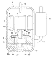
- FIG. 1 is a sectional view showing an embodiment of the compressor of the present invention.
- This compressor is a so-called high pressure dome type rotary compressor, and has a casing 1 with a compression mechanism 2 on the bottom and a motor 3 on the top.
- the rotor 6 of the motor 3 drives the compression mechanism 2 via the drive shaft 12.
- the compression mechanism 2 sucks the refrigerant from the accumulator 10 through the suction pipe 11.
- This refrigerant is obtained by controlling a condenser, an expansion mechanism, and an evaporator (not shown) constituting an air conditioner as an example of a refrigeration system together with a compressor.
- the compressor discharges compressed high-temperature and high-pressure discharge gas from the compression mechanism 2 and fills the inside of the casing 1, and after cooling the motor 3 through the gap between the stator 5 and the rotor 6 of the motor 3,
- the discharge pipe 13 discharges to the outside.
- Lubricating oil 9 is stored in the lower portion of the high pressure region in the casing 1.
- the compression mechanism 2 includes a cylinder body 21 that forms a compression chamber (cylinder chamber) 22, and an upper side that is attached to the upper and lower end surfaces of the cylinder body 21 and covers the compression chamber 22.
- An end face member 23 and a lower end face member 60 are provided.
- the drive shaft 12 passes through the upper end face member 23 and the lower end face member 60 and enters the compression chamber 22.
- a roller 27 fitted to a crank pin 26 provided on the drive shaft 12 is disposed in the compression chamber 22 so as to be able to revolve, and a compression action is performed by the revolving motion of the roller 27.
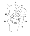
- the inside of the compression chamber 22 is partitioned by a blade 28 provided integrally with the roller 27. That is, as shown in FIG. 2, the cylinder body 21 has a cylinder suction hole 21 a that is open on the inner surface of the compression chamber 22, and the suction pipe 11 inserted into the cylinder suction hole 21 a is provided in the compression chamber 22.
- the refrigerant is supplied through the chamber, but the chamber on the right side of the blade 28 forms a suction chamber 22a in which a cylinder suction hole 21a is opened.
- the chamber on the left side of the blade 28 forms a discharge chamber 22 b in which the discharge hole 23 a shown in FIG. 1 is opened on the inner peripheral surface of the compression chamber 22.
- a semicircular bush is in close contact with both surfaces of the blade 28 for sealing. Lubricating is performed with the lubricating oil 9 between the blade 28 and the bush.
- a crank pin 26 that rotates together with the drive shaft 12 rotates eccentrically, and a roller 27 fitted to the crank pin 26 uses the outer peripheral surface of the roller 27 as the inner peripheral surface of the compression chamber 22. Revolves in contact with As the roller 27 revolves in the compression chamber 22, the blade 28 advances and retreats with both side surfaces of the blade 28 held by bushes. Then, a low-pressure refrigerant is sucked into the suction chamber 22a from the suction pipe 11, compressed in the discharge chamber 22b to a high pressure, and then the high-pressure refrigerant is discharged from the discharge hole 23a.
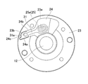
- the upper end surface of the end surface member 23 is provided with a concave portion (recessed portion) 24.
- a plate-like discharge valve 31 and a plate-like valve pressing member 32 are provided in the recess 24 of the end surface member 23.
- the recess 24 of the end face member 23 is provided with an elliptical discharge hole 23a communicating with the compression chamber 22 and a through hole 23b disposed in the vicinity of the discharge hole 23a.
- the annular convex part 25 is arrange
- the upper end of the annular convex portion 25 has a substantially semicircular cross section, and is highest at the central portion of the annular convex portion 25.
- the central part of the annular convex part 25 is the top part 25 a of the annular convex part 25.
- illustration of some members such as the valve pressing member 32 is omitted, and the top portion 25 a of the annular convex portion 25 is illustrated by a two-dot chain line.
- the discharge valve 31 is a member that opens and closes the annular convex portion 25 around the discharge hole 23 a
- the valve pressing member 32 is a member that sandwiches the discharge valve 31 in cooperation with the end surface member 23.
- the discharge valve 31 has a hole 31a
- the valve pressing member 32 has a hole 32a.
- the hole 31a and the hole 32a are substantially the same size as the through hole 23b.
- the recess 24 of the end face member 23 has a side wall 24a and a side wall 24b that are substantially opposed to each other.
- the side wall 24a and the side wall 24b extend from the through hole 23b to the discharge hole 23a side.
- the side wall 24a and the side wall 24b of the recessed part 24 are located in the both sides of this site
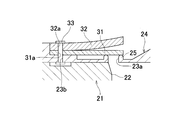
- the discharge valve 31 and the valve pressing member 32 are fixed to the end surface member 23 by a rivet 33.
- the rivet 33 is inserted into the hole portion 31 a of the discharge valve 31 and the hole portion 32 a of the valve pressing member 32 and is also inserted into the through hole 23 b of the end surface member 23, so that the discharge valve 31 is connected to the end surface member 23 and the valve pressing member 32. Fix it in the state of being pinched by.
- the discharge valve 31 closes the annular convex portion 25 around the discharge hole 23a in the free state.
- the discharge valve 31 is elastically deformed so as to leave the annular convex portion 25, and the compressed gas is discharged from the discharge hole 23a.
- the valve pressing member 32 suppresses the movement of the discharge valve 31 so that the discharge valve 31 is not deformed (oscillated) more than necessary.
- a muffler body 40 is attached to the end face member 23 so as to cover the discharge valve 31.
- the muffler main body 40 is fixed to the end surface member 23 by a fixing member such as a bolt.
- a muffler chamber (muffler space) 41 is formed by the muffler main body 40 and the end face member 23.
- the muffler chamber 41 and the cylinder chamber 22 communicate with each other through the discharge hole 23a.
- the muffler main body 40 has a hole, and the muffler chamber 41 communicates with the space in the casing 1 through the hole.
- the surface of the end surface member 23 where the recess 24 is formed is opposed to the muffler chamber 41.
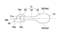
- the discharge valve 31 includes a fixed portion 52 that is fixed to the through hole 23 b of the end surface member 23 via the hole portion 31 a, a flexible portion 53 that extends from the fixed portion 52, The head portion 54 is disposed on the distal end side of the flexible portion 53 and has a head portion 54 facing the annular convex portion 25.
- description will be made assuming that the center position of the hole 31 a of the discharge valve 31 coincides with the center position of the through hole 23 b of the end face member 23.
- the fixing part 52 has a hole 31a and is a part fixed to the end face member 23 between the side wall 24a and the side wall 24b of the recess 24.
- the width of the fixing portion 52 (the vertical width in FIG. 5) is configured to be slightly smaller than the distance between the side wall 24a and the side wall 24b of the recess 24 in consideration of assembly errors.
- the fixed portion 52 has a protruding portion 58 formed at the rear end thereof.
- the protrusion 58 is configured in a rectangular shape in plan view.
- One side surface 58a of the protruding portion 58 is substantially flush with the side surface 52a of the fixed portion 52 on the bearing portion 12 side.
- the protrusion 58 is disposed in a region (one region) on the bearing 12 side from the center line of the discharge valve 31. Therefore, the other side surface 58b of the protruding portion 58 is disposed in a region closer to the bearing portion 12 than the center line of the discharge valve 31, like the one side surface 58a, and the entire protruding portion 58 is bearing from the center line of the discharge valve 31. It is arranged in the area on the part 12 side.
- a rear end portion of the side surface 52b of the fixed portion 52 opposite to the bearing portion 12 (a side surface 52b on the side that is not substantially flush with the protruding portion 58 of the fixed portion 52) is configured in a curved shape.
- the recess 24 is configured along the rear end portion of the fixed portion 52. Accordingly, a part of the rear end side of the concave portion 24 is configured to protrude in substantially the same shape as the protruding portion 58. Accordingly, one side surface 58a of the protruding portion 58 faces the side wall 24a of the concave portion 24, and the other side surface 58b of the protruding portion 58 faces the side wall 24c corresponding to the portion protruding to the rear end side of the concave portion 24.
- the width of the protrusion 58 (the vertical width in FIG. 5) is configured to be slightly smaller than the distance between the side wall 24a and the side wall 24c of the recess 24 in consideration of assembly errors.
- the discharge valve 31 is fixed when the discharge valve 31 rotates around the hole 31a so that the head of the discharge valve 31 moves away from the bearing portion 12 in the recess 24.
- the side surface 58 a of the protruding portion 58 of the portion 52 contacts the side wall 24 a of the recess 24.
- the protruding portion of the fixed portion 52 A side surface 58 b of 58 abuts on the side wall 24 c of the recess 24.
- the flexible portion 53 is configured to be narrower than the fixed portion 52, and is a portion that bends and elastically deforms when the refrigerant in the compression chamber 22 reaches a predetermined pressure.
- the head portion 54 is configured to be wider than the flexible portion 53, and is a portion that opens and closes the annular convex portion 25 around the discharge hole 23a.
- one side surface 54 a of the head 54 has a first straight portion 55
- the other side surface 54 b of the head 54 has a second straight portion 56.
- tip part 57 of the head 54 is comprised by curve shape in planar view.
- the discharge hole 23a is configured in an elliptical shape.
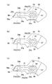
- 6 (a) to 6 (c) show a state before the discharge valve 31 is disposed in the recess 24 and fixed to the end face member 23.
- the illustration of the members of the part is omitted, and the position corresponding to the top part 25a of the elliptical annular convex part 25 is shown by a two-dot chain line.
- FIG. 6 (b) when the center line of the discharge valve 31 coincides with a straight line passing through the center of the through hole 23b of the end surface member 23 and the center of the elliptical discharge hole 23a in plan view, It is considered that the discharge valve 31 is properly arranged with respect to the end face member 23.
- the head 54 properly closes the annular convex portion 25 having an elliptical shape. Can be in a state.
- the discharge valve 31 rotates around the hole 31a (through hole 23b) (centered around the through hole 23b) in the plan view, and the first straight portion of the head 54
- the protrusion of the fixing portion 52 When the side surface 58a of the portion 58 contacts the side wall 24a of the recess 24, the rotation of the discharge valve 31 is restricted.
- the discharge valve 31 When the discharge valve 31 is in a position where it cannot rotate any more in the above direction, the first straight portion 55 of the head 54 is disposed outside the annular convex portion 25.
- the length of the first straight portion 55 of the head 54 is configured to be substantially the same as the length of the straight portion along the major axis of the top portion 25a of the elliptical annular convex portion 25.
- the side surface 58b of the protruding portion 58 of the fixing portion 52 is recessed 24. Rotation of the discharge valve 31 is restricted by contacting the side wall 24c.
- the second straight portion 56 of the head 54 is disposed outside the annular convex portion 25.
- the length of the second straight portion 56 of the head 54 is configured to be substantially the same as the length of the straight portion along the long axis of the top portion 25a of the elliptical annular convex portion 25.
- the discharge valve 31 may be inclined in a predetermined range between the position shown in FIG. 6A and the position shown in FIG. 6C.
- the front end portion 57 is disposed outside the top portion 25 a on the side away from the through hole 23 b of the annular convex portion 25. Accordingly, the annular convex portion 25 having the elliptical head portion 54 can be properly closed.
- the rear end of the fixed portion 52 has a protruding portion 58 that is flush with the side surface of the fixed portion 52 on the bearing portion 12 side, and the discharge valve 31 is in the recess 24.
- the discharge valve 31 rotates around the hole 31a in one direction (so that the head 54 of the discharge valve 31 moves away from the bearing portion 12).
- one side surface 58a of the protrusion 58 contacts the side wall 24a of the recess 24, the discharge valve 31 is prevented from rotating and tilting in one direction. Therefore, it is possible to prevent the head 54 of the discharge valve 31 from properly closing the annular convex portion 25.
- the recessed part 24 is comprised along the rear-end part of the fixing
- the discharge valve 31 rotates about the hole 31a in the other direction (so that the head 54 of the discharge valve 31 moves toward the bearing portion 12)
- the other side surface 58b of the protrusion 58 is the recess 24. Since the contact with the side wall 24c of the discharge valve 31 is prevented from rotating and tilting in the other direction. Therefore, it is possible to prevent the head 54 of the discharge valve 31 from properly closing the annular convex portion 25.
- the discharge valve 31 is the above-mentioned. It is possible to effectively suppress rotation and tilting in the other direction.
- the protruding portion 58 when the muffler main body 40 is attached to the end face of the end face member 23, the protruding portion 58 is disposed in a region closer to the bearing portion 12 than the center line of the discharge valve 31, so that, for example, the protruding portion Compared with the case where the portion 58 is disposed in the entire region of the discharge valve 31, the recess 24 can be made smaller, and the seal area between the end surface of the end surface member 23 and the muffler body 40 can be increased.
- the discharge valve 31 is in one direction (its head 54 is The fixing portion 52 of the discharge valve 31 before the side surface 58a on the bearing portion 12 side of the protrusion 58 of the discharge valve 31 contacts the side wall 24a of the recess 24 when rotating and tilting in the direction away from the bearing portion 12). It is possible to prevent the side surface 52 b opposite to the bearing portion 12 from coming into contact with the side wall 24 b of the recess 24.
- the reliability due to the twisting of the valve at the time of opening and closing of the valve which occurs when the longitudinal direction of the discharge valve 31 does not coincide with the long axis direction of the discharge hole 23a.
- the fixing part 52 is shortened, but even in this case, the discharge valve 31 can be prevented from tilting.
- the seal area between the end face of the end face member 23 and the muffler main body 40 can be increased, the refrigerant can be prevented from leaking from the muffler space.
- FIG. 7 shows a second embodiment of the present invention.
- the protruding portion 58 of the discharge valve 31 is disposed in a partial region of the rear end of the discharge valve 31, whereas in the second embodiment, the protruding portion 158 of the discharge valve 131 is discharged. It differs in the point arrange
- a concave portion (recessed portion) 124 is provided on the upper end surface of the end surface member 23.
- a plate-like discharge valve 131 and a plate-like valve pressing member 32 are arranged in the recess 124 of the end surface member 23.
- the concave portion 124 of the end face member 23 is provided with a circular discharge hole 123a communicating with the compression chamber 22 and a through hole 23b provided in the vicinity of the discharge hole 123a.
- An annular convex portion 125 is disposed around the discharge hole 123 a in the concave portion 124.
- the upper end of the annular protrusion 125 has a substantially semicircular cross section, and is highest at the center of the annular protrusion 125. Therefore, the central portion of the annular convex portion 125 is the top portion 125 a of the annular convex portion 125.
- the discharge valve 131 is a member that opens and closes the annular convex portion 125 around the discharge hole 123a.
- the discharge valve 131 has a hole 131a.
- the hole 131a is slightly larger than the through hole 23b.
- the concave portion 124 of the end face member 23 has a side wall 124a and a side wall 124b that are substantially opposed to each other.
- the discharge valve 131 is disposed on the distal end side of the flexible portion 153, a fixed portion 152 that is fixed to the through hole 23 b of the end surface member 23 via the hole portion 131 a, a flexible portion 153 that extends from the fixed portion 152, and the flexible portion 153. And an annular convex portion 125 and a head portion 154 facing the annular convex portion 125.
- the fixing part 152 has a hole 131a and is a part fixed to the end face member 23 between the side wall 124a and the side wall 124b of the recess 124.
- the width of the fixing portion 152 (the vertical width in FIG. 7) is configured to be slightly smaller than the distance between the side wall 124a and the side wall 124b of the recess 124 in consideration of assembly errors.
- the fixed portion 152 has a protruding portion 158 formed at the rear end thereof.
- the projecting portion 158 has an inclined surface (in addition to the projecting portion 158), the projecting amount increases in the plan view from the side surface 152 b on the opposite side of the bearing portion 12 of the fixed portion 152 to the side surface 152 a on the bearing portion 12 side of the fixed portion 152.
- Side 158b One side surface 158a of the protruding portion 158 is configured to be substantially flush with the side surface 152a of the fixed portion 152 on the bearing portion 12 side.
- the protrusion 158 is disposed in the entire width region of the rear end of the discharge valve 131. And the rear-end part of the side surface 152b on the opposite side to the bearing part 12 of the fixing
- the recess 124 is configured along the rear end portion of the fixing portion 152. Therefore, a part of the rear end side of the concave portion 124 is configured to protrude in substantially the same shape as the protruding portion 158. Therefore, one side surface 158a of the protrusion 158 faces the side wall 124a of the recess 124, and the other side surface 158b of the protrusion 158 faces the side wall 124c corresponding to the portion protruding to the rear end side of the recess 124.
- the width of the protruding portion 158 (the vertical width in FIG. 7) is configured to be slightly smaller than the distance between the side wall 124a and the side wall 124c of the recess 124 in consideration of assembly errors.
- the discharge valve 131 is fixed when the discharge valve 131 rotates around the hole 131a so that the head of the discharge valve 131 moves away from the bearing portion 12 in the recess 124.
- a side surface 158 a of the projecting portion 158 of the portion 152 contacts the side wall 124 a of the recess 124.
- the protruding portion of the fixed portion 152 A side surface 158 b of 158 contacts the side wall 124 c of the recess 124.
- the flexible portion 153 is configured to have a narrower width than the fixed portion 152, and is a portion that bends and elastically deforms when the refrigerant in the compression chamber 22 reaches a predetermined pressure.
- the head portion 154 is configured to be wider than the flexible portion 153, and is a portion that opens and closes the annular convex portion 125 around the discharge hole 123a.
- the discharge hole 123a is configured in an elliptical shape.
- 7A to 7C show a state before the discharge valve 131 is disposed in the recess 124 and fixed to the end face member 23.
- the illustration of the members of the part is omitted, and the position corresponding to the top part 125a of the elliptical annular convex part 125 is shown by a two-dot chain line.
- FIG. 7B when the center line of the discharge valve 131 coincides with a straight line passing through the center of the through hole 23b of the end face member 23 and the center of the elliptical discharge hole 123a in plan view, It is considered that the discharge valve 131 is properly disposed with respect to the end face member 23.
- the head 154 When the discharge valve 131 is fixed in this state, since the discharge valve 131 is in an appropriate fixing position (a position where the discharge valve 131 is not inclined), the head 154 appropriately closes the elliptical annular convex portion 125. Can be in a state.
- the discharge valve 131 may be inclined in a predetermined range between the position shown in FIG. 7A and the position shown in FIG. 7C.
- the front end portion 157 is disposed outside the top portion 125 a of the annular convex portion 125. Accordingly, the annular convex portion 125 having the elliptical head portion 154 can be properly closed.
- FIG. 8 shows a third embodiment of the present invention.
- the compressor according to the first embodiment and the compressor according to the third embodiment are different in the arrangement of the elliptical discharge holes with respect to the drive shaft. Accordingly, in the first embodiment, the compressor is disposed in the recess 24 of the end surface member 23. In contrast to the head 54 of the discharge valve 31 that is disposed without being inclined with respect to the flexible portion 53, in the third embodiment, the head of the discharge valve 231 that is disposed in the recess 224 of the end face member 23.
- the part 254 is disposed to be inclined with respect to the flexible part 253. Since other configurations are substantially the same as those in the first embodiment, the description thereof is omitted.
- the discharge valve 231 rotates around the hole 231a (through hole 23b) in the plan view, and the head 254 moves away from the drive shaft 12.
- the side surface on the drive shaft 12 side of the protruding portion 258 of the fixing portion 252 contacts the side wall of the recess 224.
- the rotation of the discharge valve 231 is restricted.
- the discharge valve 231 When the discharge valve 231 is in a position where the discharge valve 231 cannot rotate any more in the above direction and the discharge valve 231 is fixed in this state, the discharge valve 231 is not fixed at the proper fixed position, and the head of the discharge valve 231 Although the portion 254 is fixed in a state of being inclined in a direction away from the drive shaft 12, the head 254 can appropriately close the annular convex portion 225 (the top portion 225a) around the elliptical discharge hole 223a.
- the discharge valve 231 When the discharge valve 231 is in a position where the discharge valve 231 cannot rotate any more in the above direction and the discharge valve 231 is fixed in this state, the discharge valve 231 is not fixed at the proper fixed position, and the head of the discharge valve 231 Although the portion 254 is fixed in a state of being inclined in a direction approaching the drive shaft 12, the head 254 can properly close the elliptical annular convex portion 225.
- FIG. 9 shows a fourth embodiment of the present invention.
- the rotary compressor to which the present invention is applied has been described.
- a scroll compressor to which the present invention is applied will be described.
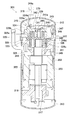
- a scroll compressor 301 shown in FIG. 9 is a high and low pressure dome type scroll compressor, and forms a refrigerant circuit together with an evaporator, a condenser, an expansion mechanism, and the like, and compresses gas refrigerant in the refrigerant circuit. It mainly comprises a vertically long cylindrical sealed dome-shaped casing 310, a scroll compression mechanism 315, an Oldham ring 339, a drive motor 316, a suction pipe 319, and a discharge pipe 320.
- the casing 310 has a substantially cylindrical body casing part 311, a bowl-shaped upper wall part 312 welded in an airtight manner to the upper end part of the body part casing part 311, and an airtight state at the lower end part of the body part casing part 311. And a bowl-shaped bottom wall portion 313 which is welded to each other.
- the casing 310 mainly accommodates a scroll compression mechanism 315 that compresses the gas refrigerant and a drive motor 316 disposed below the scroll compression mechanism 315.
- the scroll compression mechanism 315 and the drive motor 316 are connected to each other by a drive shaft 317 arranged so as to extend in the vertical direction in the casing 310. As a result, a gap space 318 is generated between the scroll compression mechanism 315 and the drive motor 316.
- the scroll compression mechanism 315 mainly includes a housing 323, a fixed scroll 324 arranged in close contact with the housing 323, and a movable scroll 326 that meshes with the fixed scroll 324. ing.
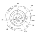
- the fixed scroll 324 mainly includes a flat end plate 324a and a spiral (involute) wrap 324b formed on the lower surface of the end plate 324a.
- the discharge port 341 is formed to extend in the vertical direction at the center portion of the end plate 324a.
- the shape of the opening surface of the discharge port 341 is a non-circular shape in order to increase the opening area and reduce the discharge pressure loss.
- a counterbore space 341a communicating with the discharge port 341 is formed on the upper surface of the end plate 324a.
- an enlarged recess 342 communicating with the discharge port 341 and the counterbore space 341a is formed on the upper surface of the end plate 324a.
- the enlarged recess 342 is configured by a recess that extends in the horizontal direction and is provided in the upper surface of the end plate 324a.
- a lid 344 is fastened and fixed to the upper surface of the fixed scroll 324 by a bolt 344 a so as to close the enlarged concave portion 342.
- the muffler space 345 which consists of an expansion chamber which silences the driving
- the fixed scroll 324 and the lid 344 are sealed by being brought into close contact via a packing (not shown).
- four sets of round hole-shaped relief holes 361 are formed through the end plate 324 a of the fixed scroll 324 by two. Specifically, the relief hole 361 is arranged so that the compression chamber 340 passes through the four relief holes 361 for each compression process from suction to discharge.
- the relief hole 361 is formed at a position spaced from the wrap 324b of the fixed scroll 324 as shown in FIG.
- a common counterbore hole 365 communicating with each of the two relief holes 361 is formed on the back side (near the upper surface) of the end plate 324a.
- a relief passage 370 that penetrates the end plate 324 a of the fixed scroll 324 is formed by the relief hole 361 and the counterbore hole 365.
- a relief valve 366 that is a check valve for closing each counterbore hole 365, and an opening of the relief valve 366.
- a relief valve retainer 367 is provided for limiting the degree to a predetermined opening or less.
- the movable scroll 326 mainly includes a mirror plate 326a, a spiral (involute) wrap 326b formed on the upper surface of the mirror plate 326a, and a bearing portion 326c formed on the lower surface of the mirror plate 326a. And a groove portion 326d formed at both ends of the end plate 326a.
- the movable scroll 326 is an outer drive movable scroll. That is, the movable scroll 326 has a bearing portion 326 c that fits outside the drive shaft 317.
- the movable scroll 326 is supported by the housing 323 by fitting the Oldham ring 339 into the groove 326d. Further, the upper end of the drive shaft 317 is fitted into the bearing portion 326c. The movable scroll 326 revolves in the housing 323 without being rotated by the rotation of the drive shaft 317 by being incorporated in the scroll compression mechanism 315 in this way.
- the wrap 326b of the movable scroll 326 is engaged with the wrap 324b of the fixed scroll 324, and a compression chamber 340 is formed between the contact portions of both the wraps 324b and 326b. In the compression chamber 340, as the movable scroll 326 revolves, the volume between the wraps 324b and 326b contracts toward the center.
- the gas refrigerant is compressed in this way.
- a communication passage 346 is formed in the scroll compression mechanism 315 so as to extend between the fixed scroll 324 and the housing 323.
- the communication passage 346 is formed such that a scroll side passage 347 formed in the fixed scroll 324 and a housing side passage 348 formed in the housing 323 are communicated.
- the upper end of the communication passage 346 opens to the enlarged recess 342, and the lower end of the communication passage 346, that is, the lower end of the housing side passage 348 opens to the lower end surface of the housing 323.
- the lower end opening of the housing side passage 348 constitutes a discharge port 349 through which the refrigerant in the communication passage 346 flows out to the gap space 318.
- the suction pipe 319 is for guiding the refrigerant in the refrigerant circuit to the scroll compression mechanism 315, and is fitted into the upper wall 312 of the casing 310 in an airtight manner.
- the suction pipe 319 passes through the low pressure space 329 in the vertical direction, and an inner end portion is fitted into the fixed scroll 324.
- the discharge pipe 320 is for discharging the refrigerant in the casing 310 to the outside of the casing 310, and is fitted into the body casing portion 311 of the casing 310 in an airtight manner.
- the discharge pipe 320 is opened at a position protruding downward from the inner surface of the body toward the center, and communicates with a gap space 318 that is a high-pressure space 328.
- the operation of the scroll compressor 301 will be briefly described with reference to FIG. First, when the drive motor 316 is driven, the drive shaft 317 is rotated, and the revolving operation is performed without the movable scroll 326 rotating. Then, the low-pressure gas refrigerant is sucked into the compression chamber 340 from the peripheral side of the compression chamber 340 through the suction pipe 19 and is compressed along with the volume change of the compression chamber 340 to become a high-pressure gas refrigerant. The high-pressure gas refrigerant is discharged from the central portion of the compression chamber 340 to the muffler space 345 through the discharge port 341 and the counterbore space 341a.
- the overcompressed gas When overcompressed gas is generated in the compression chamber 340 (when the internal pressure of the compression chamber 340 is equal to or higher than the valve closing pressure of the relief valve 366), the overcompressed gas is discharged to the muffler space 345 through the relief passage 370. . Thereafter, the fluid flows out to the gap space 318 through the communication passage 346 (that is, the scroll-side passage 347 and the housing-side passage 348) and the discharge port 349, and the space between the guide plate 358 and the inner surface of the body casing portion 311 is lowered. It flows toward.
- the gas refrigerant that has passed through the guide plate 358 and the gas refrigerant that has flowed through the air gap passage or the motor cooling passage 355 merge in the gap space 318 and are discharged from the discharge pipe 320 to the outside of the casing 310.
- the gas refrigerant discharged to the outside of the casing 310 circulates through the refrigerant circuit, and then is again sucked into the scroll compression mechanism 315 through the suction pipe 319 and compressed.
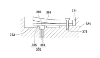
- a concave portion (recessed portion) 371 is provided on the upper end surface of the fixed scroll 324.
- Four concave portions 371 are provided on the upper end surface of the fixed scroll 324. Since the configuration is substantially the same, one concave portion 371 will be described with reference to FIGS. Description is omitted.
- a plate-like relief valve 366 and a plate-like relief valve presser 367 are provided in the concave portion 371 of the fixed scroll 324.
- a circular counterbore space 365 communicating with the compression chamber 340 and a through-hole 372 disposed in the vicinity of the counterbore space 365 are provided in the recess 371 of the fixed scroll 324.
- An annular convex portion 373 is disposed around the spot facing space 365 in the concave portion.
- the relief valve 366 is a member that opens and closes the annular convex portion 373 around the counterbore space 365
- the relief valve presser 367 is a member that cooperates with the fixed scroll 324 to sandwich the relief valve 366.
- the recessed portion 371 of the fixed scroll 324 has a side wall 371a and a side wall 371b that are substantially opposed to each other.
- the side wall 371a and the side wall 371b extend from the through hole 372 toward the counterbore space 365.
- the side wall 371a and the side wall 371b of the recessed part 371 are located in the both sides of this site
- the relief valve 366 closes the annular convex portion 373 around the counterbore space 365 in the free state.
- the relief valve 366 elastically deforms away from the annular convex portion 373 and the compressed gas is discharged from the counterbore space 365.
- the relief valve 366 is fixed to the through hole 372 b of the fixed scroll 324. It has a fixed portion 374, a flexible portion 375 extending from the fixed portion 374, and a head portion 376 that is disposed on the distal end side of the flexible portion 375 and faces the annular convex portion 373.
- the fixing portion 374 has a protruding portion 377 formed at the rear end thereof.
- the protruding portion 377 is configured in a rectangular shape in plan view.
- One side surface 377 a of the protruding portion 377 is configured to be substantially flush with the central side surface of the fixed scroll 324 in the fixed portion 374.
- the protruding portion 377 is disposed in a region (one region) on the center side of the fixed scroll 324 from the center line of the relief valve 366.
- the rear end portion of the fixed portion 374 opposite to the center of the fixed scroll 324 (the side surface of the fixed portion 374 that is not substantially flush with the protruding portion 377) has a curved shape.
- the relief valve 366 when the relief valve 366 is fixed to the through-hole 372b of the fixed scroll 324, the relief valve 366 is in the recess 373, and the head 376 of the relief valve 366 is When the relief valve 366 rotates around the through hole 372b so as to move toward or away from the center of the compression chamber 340, the side surface of the protruding portion 377 of the fixing portion 374 contacts the side wall of the recess 371. Is suppressed from tilting.
- the discharge valve in a state before the discharge valve is disposed in the recess and fixed to the end face member, the discharge valve is moved so that the head of the discharge valve moves toward the bearing portion.
- the discharge valve When the discharge valve is rotated about the hole so that the head of the head moves away from the bearing portion, one side surface of the projecting portion may abut against the side wall of the recess. This is the same in the fourth embodiment.
- the recess is formed along the rear end portion of the fixed portion, and the discharge valve is disposed in the recess and is fixed to the end face member in the state before the discharge valve.
- the discharge valve is not configured along the end portion, and the discharge valve is arranged so that the head of the discharge valve moves in a direction approaching the bearing portion in a state before the discharge valve is disposed in the recess and fixed to the end surface member.
- the shape of the projecting portion is You may change arbitrarily.
- the protruding portion is rectangular, not only when the entire protruding portion is arranged in the region closer to the bearing portion than the center line of the discharge valve, but a part of the protruding portion is bearing from the center line of the discharge valve. You may arrange
- the present invention is not limited to this. Therefore, in one side surface of the projecting portion, there is a recess in a part on the front end side from the rear end, and the entire one side surface of the projecting portion is not substantially flush with the side surface on the bearing portion side of the fixed portion.
- the effect of the present invention can be obtained when at least the rear end of one side surface of the protruding portion is substantially on the same plane when the side surface of the fixed portion on the bearing portion side is extended. This is the same in the fourth embodiment.
- the rear end portion of the side surface opposite to the bearing portion of the fixed portion is configured in a curved shape in a plan view.
- the rear end portion of the side surface may be configured to be perpendicular to the side surface of the fixing portion. This is the same in the fourth embodiment.
- the discharge hole is elliptical
- the discharge hole may be circular, and the shape of the discharge hole can be changed. This is the same in the fourth embodiment.
- the discharge valve is fixed with a rivet to the through hole of the end surface member as a fixing hole, but the discharge valve may be fixed to the end surface member with a fixing bolt.
- the fixing hole may be a through hole that is a screw hole of the end face member, or may be a hole that is not a through hole that is a screw hole of the end face member. This is the same in the fourth embodiment.
- the upper end of the annular convex portion has a substantially semicircular cross section, and is configured to be highest at the central portion of the annular convex portion. May be configured to have the same height. In this case, the entire upper end of the annular protrusion is the top of the annular protrusion. This is the same in the fourth embodiment.
- one side surface of the protruding portion is configured to be substantially flush with the side surface of the fixed portion on the bearing portion side.
- one side surface of the protruding portion is fixed. It may be configured to be substantially flush with the side surface opposite to the bearing portion.
- one side surface of the projecting portion is configured to be substantially flush with the side surface on the center side of the fixed scroll in the fixed portion has been described in all four relief valves. In at least one of the valves, one side surface of the protruding portion may be substantially flush with the side surface of the fixed portion opposite to the center of the fixed scroll.
- the present invention is applied to the relief valve and the recess in which the relief valve is disposed in the scroll compressor has been described.
- the present invention may be applied to the recess in which the discharge valve is disposed. Therefore, for example, in a compressor similar to the scroll compressor of FIG. 9, a discharge port 341 communicating with the compression chamber 340 is formed through substantially the center of the end plate 324a, and around the discharge port 341 of the end plate 324a.
- the present invention can be applied even if a recess is provided and a reed valve type discharge valve is disposed in the recess.
- the present invention is applied to all of the four relief valves and the recesses in which the relief valves are arranged has been described. However, the four relief valves and the relief valves are arranged.
- the present invention may be applied to at least one of the recessed portions to be formed, or may have only one relief valve, and the number of relief valves may be changed, for example, having two relief valves. It's okay.
- a relief valve may be provided and a discharge valve may not be provided, or a relief valve may not be provided and a discharge valve may be provided, or a relief valve may be provided. And a discharge valve may be provided.
- the discharge valve can be prevented from tilting due to assembly.
Abstract
Description
図1は、この発明の圧縮機の一実施形態である断面図を示している。この圧縮機は、いわゆる高圧ドーム型のロータリ圧縮機であって、ケーシング1内に圧縮機構2を下に、モータ3を上に配置している。このモータ3のロータ6によって、駆動軸12を介して圧縮機構2を駆動するようにしている。 (First embodiment)
FIG. 1 is a sectional view showing an embodiment of the compressor of the present invention. This compressor is a so-called high pressure dome type rotary compressor, and has a
本実施形態の圧縮機では、固定部52の後端に、固定部52の軸受部12側の側面と面一に構成された突出部58を有しており、吐出弁31が凹部24内に配置され且つ端面部材23に固定される前の状態において、吐出弁31が一方向に(吐出弁31の頭部54が軸受部12から離れる方向に移動するように)孔部31aを中心として回転した場合に、突出部58の一側面58aが凹部24の側壁24aと当接するので、吐出弁31が一方向に回転して傾くのが抑制される。したがって、吐出弁31の頭部54が環状凸部25を適正に閉状態にできなくなるのを防止できる。 <Characteristics of the compressor of this embodiment>
In the compressor of the present embodiment, the rear end of the fixed
図7は、この発明の第2実施形態を示している。第1実施形態の圧縮機では、吐出弁31の突出部58が吐出弁31の後端の一部領域に配置されるのに対し、第2実施形態では、吐出弁131の突出部158が吐出弁131の後端の幅全体の領域に配置される点で異なっており、それにともなって、端面部材の凹部の形状が異なっている。なお、その他の構成は、第1実施形態と略同一の構成であるため、その説明を省略する。 (Second Embodiment)
FIG. 7 shows a second embodiment of the present invention. In the compressor of the first embodiment, the protruding
本実施形態の圧縮機では、第1実施形態の圧縮機と同様の効果が得られる。 <Characteristics of the compressor of this embodiment>
In the compressor of this embodiment, the same effect as the compressor of the first embodiment is obtained.
図8は、この発明の第3実施形態を示している。第1実施形態の圧縮機と第3実施形態の圧縮機では、楕円形状の吐出孔の駆動軸に対する配置が異なっており、それにともなって、第1実施形態では、端面部材23の凹部24内に配置される吐出弁31の頭部54が可撓部53に対して傾斜しないで配置されるのに対し、第3実施形態では、端面部材23の凹部224内に配置される吐出弁231の頭部254が可撓部253に対して傾斜して配置されている。なお、その他の構成は、第1実施形態と略同一の構成であるため、その説明を省略する。 (Third embodiment)
FIG. 8 shows a third embodiment of the present invention. The compressor according to the first embodiment and the compressor according to the third embodiment are different in the arrangement of the elliptical discharge holes with respect to the drive shaft. Accordingly, in the first embodiment, the compressor is disposed in the
本実施形態の圧縮機では、第1実施形態の圧縮機と同様の効果が得られる。 <Characteristics of the compressor of this embodiment>
In the compressor of this embodiment, the same effect as the compressor of the first embodiment is obtained.
図9は、この発明の第4実施形態を示している。第1実施形態では、本発明が適用されたロータリ圧縮機を説明したのに対し、本実施形態では、本発明が適用されたスクロール圧縮機について説明する。 (Fourth embodiment)
FIG. 9 shows a fourth embodiment of the present invention. In the first embodiment, the rotary compressor to which the present invention is applied has been described. In the present embodiment, a scroll compressor to which the present invention is applied will be described.
本実施形態の圧縮機では、第1実施形態の圧縮機と同様の効果が得られる。従来のスクロール圧縮機において、近年、期間効率を向上させるため、低圧縮比重視の設計が求められており、例えば、従来リリーフ弁が2つであったところに、本実施形態のように、4つのリリーフ弁を配置する場合がある。その場合、固定スクロールへの凹部の配置、およびリード弁型のリリーフ弁の固定部の長さが、固定スクロールの径寸法による制約を受け、リリーフ弁に傾きが生じる場合がある。その場合にも、リリーフ弁の傾きを防止し、リリーフポートを適正に閉状態にできる。 <Characteristics of the compressor of this embodiment>
In the compressor of this embodiment, the same effect as the compressor of the first embodiment is obtained. In the conventional scroll compressor, in recent years, in order to improve the period efficiency, a design with an emphasis on a low compression ratio has been demanded. There may be two relief valves. In that case, the arrangement of the recesses in the fixed scroll and the length of the fixed portion of the reed valve type relief valve are restricted by the diameter of the fixed scroll, and the relief valve may be inclined. Even in this case, the relief valve can be prevented from tilting and the relief port can be properly closed.
2 圧縮機構
3 駆動機構
21 シリンダ本体
22 圧縮室
23、123、223 端面部材 (凹部が形成された部材)
23a、123a、223a 吐出孔
23b 貫通孔
24、124、224 凹部
25、125、225 環状凸部
31、131、231 吐出弁(リード弁型の吐出弁)
31a、131a、231a 孔部
33 リベット
52、152、252 固定部
53、153、253 可撓部
54、154、254 頭部
58、158、258 突出部
340 圧縮室
366 リリーフ弁(リード弁型の吐出弁)
371 凹部
324 固定スクロール(凹部が形成された部材)
370 リリーフ通路(吐出孔)
372 貫通孔(固定孔)
373 環状凸部
374 固定部
375 可撓部
376 頭部
377 突出部 DESCRIPTION OF
23a, 123a,
31a, 131a, 231a
371
370 Relief passage (discharge hole)
372 Through hole (fixed hole)
373 Annular
Claims (7)
- 圧縮室と近接するように配置され、リード弁型の吐出弁が配置される凹部が前記圧縮室と反対側の面に形成された部材を備え、
前記凹部には、
前記圧縮室に連通する吐出孔と、
前記吐出弁を固定するための固定孔と、
前記吐出孔の周囲に形成された環状凸部とが設けられており、
前記吐出弁が、
前記部材に前記固定孔を介して固定される固定部と、
前記固定部から延在する可撓部と、
前記可撓部の先端側に配置され、前記環状凸部を開閉する頭部とを有し、
前記固定部は、その後端に形成された突出部を有しており、
前記突出部の一側面が、前記固定部の側面と略面一に構成されるとともに、
前記吐出弁が前記凹部内に配置され且つ前記部材に固定される前の状態において、
前記吐出弁が前記固定孔を中心として所定方向に回転した場合に、前記突出部の一側面が前記凹部の側壁と当接することを特徴とする圧縮機。 It is disposed so as to be close to the compression chamber, and includes a member in which a recess in which a reed valve type discharge valve is disposed is formed on the surface opposite to the compression chamber,
In the recess,
A discharge hole communicating with the compression chamber;
A fixing hole for fixing the discharge valve;
An annular projection formed around the discharge hole, and
The discharge valve is
A fixing portion fixed to the member via the fixing hole;
A flexible portion extending from the fixed portion;
A head that is disposed on a distal end side of the flexible part and opens and closes the annular convex part
The fixed portion has a protruding portion formed at a rear end thereof,
While one side surface of the protruding portion is configured to be substantially flush with the side surface of the fixed portion,
In a state before the discharge valve is disposed in the recess and fixed to the member,
The compressor according to claim 1, wherein when the discharge valve rotates in a predetermined direction about the fixed hole, one side surface of the projecting portion comes into contact with a side wall of the concave portion. - 前記凹部が、前記固定部の後端部分に沿って構成されており、
前記吐出弁が前記凹部内に配置され且つ前記部材に固定される前の状態において、
前記吐出弁が前記固定孔を中心として前記所定方向と反対方向に回転した場合に、前記突出部の他側面が前記凹部の側壁と当接することを特徴とする請求項1に記載の圧縮機。 The concave portion is configured along a rear end portion of the fixed portion;
In a state before the discharge valve is disposed in the recess and fixed to the member,
2. The compressor according to claim 1, wherein when the discharge valve rotates about the fixed hole in a direction opposite to the predetermined direction, the other side surface of the projecting portion comes into contact with a side wall of the concave portion. - 平面視において、前記突出部は矩形状であることを特徴とする請求項1または2に記載の圧縮機。 3. The compressor according to claim 1 or 2, wherein the protrusion has a rectangular shape in plan view.
- 前記突出部は、前記吐出弁の中心線より片側の領域に配置されることを特徴とする請求項1-3のいずれかに記載の圧縮機。 The compressor according to any one of claims 1 to 3, wherein the protruding portion is arranged in a region on one side of a center line of the discharge valve.
- 平面視において、前記固定部における前記突出部と略面一に構成されてない側の側面の後端部分が曲線状に構成されることを特徴とする請求項1-4のいずれかに記載の圧縮機。 5. The rear end portion of a side surface of the fixing portion that is not substantially flush with the protruding portion in a plan view is configured in a curved shape. Compressor.
- 前記吐出孔が、楕円形状であって、
前記吐出弁の長手方向が、前記吐出孔の長軸方向と一致することを特徴とする請求項1-5のいずれかに記載の圧縮機。 The discharge hole has an elliptical shape,
The compressor according to any one of claims 1 to 5, wherein a longitudinal direction of the discharge valve coincides with a long axis direction of the discharge hole. - 前記部材の前記凹部が形成された面は、マフラ空間と対向することを特徴とする請求項1-6のいずれかに記載の圧縮機。 The compressor according to any one of claims 1 to 6, wherein a surface of the member on which the concave portion is formed is opposed to a muffler space.
Priority Applications (6)
| Application Number | Priority Date | Filing Date | Title |
|---|---|---|---|
| US15/033,060 US9651049B2 (en) | 2013-11-01 | 2014-10-31 | Compressor |
| ES14857340.5T ES2648822T3 (en) | 2013-11-01 | 2014-10-31 | Compressor |
| EP14857340.5A EP3054159B1 (en) | 2013-11-01 | 2014-10-31 | Compressor |
| MX2016005685A MX354059B (en) | 2013-11-01 | 2014-10-31 | Compressor. |
| CN201480059639.5A CN105705790B (en) | 2013-11-01 | 2014-10-31 | Compressor |
| BR112016009582-0A BR112016009582B1 (en) | 2013-11-01 | 2014-10-31 | COMPRESSOR |
Applications Claiming Priority (2)
| Application Number | Priority Date | Filing Date | Title |
|---|---|---|---|
| JP2013-228394 | 2013-11-01 | ||
| JP2013228394 | 2013-11-01 |
Publications (1)
| Publication Number | Publication Date |
|---|---|
| WO2015064759A1 true WO2015064759A1 (en) | 2015-05-07 |
Family
ID=53004353
Family Applications (1)
| Application Number | Title | Priority Date | Filing Date |
|---|---|---|---|
| PCT/JP2014/079139 WO2015064759A1 (en) | 2013-11-01 | 2014-10-31 | Compressor |
Country Status (9)
| Country | Link |
|---|---|
| US (1) | US9651049B2 (en) |
| EP (1) | EP3054159B1 (en) |
| JP (1) | JP5831613B2 (en) |
| CN (1) | CN105705790B (en) |
| BR (1) | BR112016009582B1 (en) |
| ES (1) | ES2648822T3 (en) |
| MX (1) | MX354059B (en) |
| MY (1) | MY158866A (en) |
| WO (1) | WO2015064759A1 (en) |
Families Citing this family (5)
| Publication number | Priority date | Publication date | Assignee | Title |
|---|---|---|---|---|
| CN106368952A (en) * | 2016-11-07 | 2017-02-01 | 珠海格力节能环保制冷技术研究中心有限公司 | Air conditioning system, compressor and enthalpy increase assembly thereof |
| KR102565824B1 (en) * | 2017-01-18 | 2023-08-10 | 엘지전자 주식회사 | Scroll compressor |
| CN109973390A (en) * | 2017-12-27 | 2019-07-05 | 艾默生环境优化技术(苏州)有限公司 | Check valve and screw compressor |
| KR102589293B1 (en) * | 2018-05-17 | 2023-10-12 | 엘지전자 주식회사 | Compressor having one piece-type valve sheet and stopper sheet |
| DE102021105373A1 (en) * | 2021-03-05 | 2022-09-08 | Mann+Hummel Gmbh | Filter element, filter element arrangement and filter system with a filter element arrangement |
Citations (8)
| Publication number | Priority date | Publication date | Assignee | Title |
|---|---|---|---|---|
| JPS61103072A (en) * | 1984-10-25 | 1986-05-21 | Matsushita Electric Ind Co Ltd | Valve device for compressor |
| JPH1061799A (en) * | 1996-08-19 | 1998-03-06 | Daikin Ind Ltd | Reed valve fitting structure |
| JP2835063B2 (en) * | 1989-02-28 | 1998-12-14 | 株式会社東芝 | Compressor discharge valve structure |
| JP2002242837A (en) * | 2001-02-14 | 2002-08-28 | Sanyo Electric Co Ltd | Refrigerant compressor |
| WO2006062051A1 (en) * | 2004-12-06 | 2006-06-15 | Daikin Industries, Ltd. | Compressor |
| JP2008180143A (en) * | 2007-01-24 | 2008-08-07 | Daikin Ind Ltd | Hermetic compressor |
| JP2010236564A (en) | 2009-03-30 | 2010-10-21 | Fujitsu General Ltd | Discharge valve and compression machine equipped therewith |
| JP2011001830A (en) * | 2009-06-16 | 2011-01-06 | Daikin Industries Ltd | Compressor |
Family Cites Families (14)
| Publication number | Priority date | Publication date | Assignee | Title |
|---|---|---|---|---|
| US4730996A (en) * | 1985-07-29 | 1988-03-15 | Kabushiki Kaisha Toshiba | Rotary compressor with two discharge valves having different frequencies |
| US4886093A (en) * | 1988-12-20 | 1989-12-12 | Itakura Soki | Vent valve of an air pump |
| US5176170A (en) * | 1991-08-05 | 1993-01-05 | Performance Industries, Inc. | Multiple stage reed valves for use in internal combustion engines |
| JPH08219057A (en) * | 1995-02-14 | 1996-08-27 | Sanyo Electric Co Ltd | Rotary compressor |
| KR0186111B1 (en) * | 1995-04-20 | 1999-05-01 | 구자홍 | Valve structure of a hermetic electromagnetic compressor |
| KR200154567Y1 (en) * | 1995-06-03 | 1999-08-16 | 윤종용 | A discharge valve device of a compressor |
| DE19613911C1 (en) * | 1996-04-06 | 1997-07-24 | Danfoss Compressors Gmbh | Suction valve for reciprocating compressor |
| US6309194B1 (en) * | 1997-06-04 | 2001-10-30 | Carrier Corporation | Enhanced oil film dilation for compressor suction valve stress reduction |
| FR2798965B1 (en) * | 1999-09-28 | 2001-12-07 | Tecumseh Europe Sa | DISCHARGE VALVE DEVICE FOR REFRIGERANT FLUID COMPRESSOR |
| JP2002242862A (en) | 2001-02-20 | 2002-08-28 | Fujitsu General Ltd | Scroll compressor |
| JP2007514089A (en) * | 2003-09-02 | 2007-05-31 | エアーセップ・コーポレーション | Small compressor |
| JP4552432B2 (en) * | 2003-12-11 | 2010-09-29 | ダイキン工業株式会社 | Compressor |
| DE102010044898A1 (en) * | 2010-09-09 | 2012-03-15 | Schwäbische Hüttenwerke Automotive GmbH | Vacuum pump with ventilation device |
| CA2918392C (en) * | 2013-07-26 | 2021-11-09 | Barnes Group Inc. | Multiple parts reed valve and method of manufacturing |
-
2014
- 2014-10-31 WO PCT/JP2014/079139 patent/WO2015064759A1/en active Application Filing
- 2014-10-31 CN CN201480059639.5A patent/CN105705790B/en active Active
- 2014-10-31 MX MX2016005685A patent/MX354059B/en active IP Right Grant
- 2014-10-31 BR BR112016009582-0A patent/BR112016009582B1/en active IP Right Grant
- 2014-10-31 US US15/033,060 patent/US9651049B2/en active Active
- 2014-10-31 JP JP2014223274A patent/JP5831613B2/en active Active
- 2014-10-31 ES ES14857340.5T patent/ES2648822T3/en active Active
- 2014-10-31 EP EP14857340.5A patent/EP3054159B1/en active Active
- 2014-10-31 MY MYPI2016701524A patent/MY158866A/en unknown
Patent Citations (8)
| Publication number | Priority date | Publication date | Assignee | Title |
|---|---|---|---|---|
| JPS61103072A (en) * | 1984-10-25 | 1986-05-21 | Matsushita Electric Ind Co Ltd | Valve device for compressor |
| JP2835063B2 (en) * | 1989-02-28 | 1998-12-14 | 株式会社東芝 | Compressor discharge valve structure |
| JPH1061799A (en) * | 1996-08-19 | 1998-03-06 | Daikin Ind Ltd | Reed valve fitting structure |
| JP2002242837A (en) * | 2001-02-14 | 2002-08-28 | Sanyo Electric Co Ltd | Refrigerant compressor |
| WO2006062051A1 (en) * | 2004-12-06 | 2006-06-15 | Daikin Industries, Ltd. | Compressor |
| JP2008180143A (en) * | 2007-01-24 | 2008-08-07 | Daikin Ind Ltd | Hermetic compressor |
| JP2010236564A (en) | 2009-03-30 | 2010-10-21 | Fujitsu General Ltd | Discharge valve and compression machine equipped therewith |
| JP2011001830A (en) * | 2009-06-16 | 2011-01-06 | Daikin Industries Ltd | Compressor |
Non-Patent Citations (1)
| Title |
|---|
| See also references of EP3054159A4 |
Also Published As
| Publication number | Publication date |
|---|---|
| EP3054159B1 (en) | 2017-08-23 |
| JP2015110946A (en) | 2015-06-18 |
| CN105705790B (en) | 2018-03-20 |
| ES2648822T3 (en) | 2018-01-08 |
| BR112016009582A2 (en) | 2017-08-01 |
| MY158866A (en) | 2016-11-16 |
| EP3054159A4 (en) | 2016-09-28 |
| US9651049B2 (en) | 2017-05-16 |
| BR112016009582B1 (en) | 2022-05-03 |
| MX2016005685A (en) | 2016-11-25 |
| US20160252094A1 (en) | 2016-09-01 |
| JP5831613B2 (en) | 2015-12-09 |
| CN105705790A (en) | 2016-06-22 |
| MX354059B (en) | 2018-02-09 |
| EP3054159A1 (en) | 2016-08-10 |
Similar Documents
| Publication | Publication Date | Title |
|---|---|---|
| US7802972B2 (en) | Rotary type compressor | |
| WO2015064759A1 (en) | Compressor | |
| KR102400430B1 (en) | Scroll compressor | |
| JPWO2014178191A1 (en) | Scroll compressor | |
| WO2007000854A1 (en) | Fluid machine and refrigeration cycle device | |
| JP2016011620A (en) | Scroll compressor | |
| JP4638762B2 (en) | Scroll compressor | |
| WO2018131111A1 (en) | Multi-stage scroll compressor | |
| JP2014206173A (en) | Discharge mechanism of positive-displacement compressor | |
| US8172560B2 (en) | Fluid machinery having annular back pressure space communicating with oil passage | |
| JP2005264827A (en) | Scroll compressor | |
| JP5626260B2 (en) | Vane type compressor | |
| KR101044872B1 (en) | Scroll compressor | |
| JP7418190B2 (en) | rotary compressor | |
| JP2006329155A (en) | Rotary compressor | |
| WO2018003431A1 (en) | Multi-stage compressor | |
| JP2008121490A (en) | Rotary compressor | |
| JP7398642B2 (en) | Compressor with injection mechanism | |
| JP2019190468A (en) | Scroll compressor | |
| JP3972149B2 (en) | Rotary compressor | |
| JP2019138234A (en) | Compressor | |
| JP2006329156A (en) | Rotary compressor | |
| JP6821062B2 (en) | Scroll compressor | |
| JP2014227883A (en) | Compressor | |
| JP2014129756A (en) | Scroll compressor |
Legal Events
| Date | Code | Title | Description |
|---|---|---|---|
| 121 | Ep: the epo has been informed by wipo that ep was designated in this application |
Ref document number: 14857340 Country of ref document: EP Kind code of ref document: A1 |
|
| WWE | Wipo information: entry into national phase |
Ref document number: 15033060 Country of ref document: US |
|
| WWE | Wipo information: entry into national phase |
Ref document number: MX/A/2016/005685 Country of ref document: MX |
|
| NENP | Non-entry into the national phase |
Ref country code: DE |
|
| REEP | Request for entry into the european phase |
Ref document number: 2014857340 Country of ref document: EP |
|
| WWE | Wipo information: entry into national phase |
Ref document number: 2014857340 Country of ref document: EP |
|
| REG | Reference to national code |
Ref country code: BR Ref legal event code: B01A Ref document number: 112016009582 Country of ref document: BR |
|
| WWE | Wipo information: entry into national phase |
Ref document number: IDP00201603144 Country of ref document: ID |
|
| ENP | Entry into the national phase |
Ref document number: 112016009582 Country of ref document: BR Kind code of ref document: A2 Effective date: 20160428 |