WO2015064315A1 - Wave-eliminating plate securing structure in fuel tank - Google Patents
Wave-eliminating plate securing structure in fuel tank Download PDFInfo
- Publication number
- WO2015064315A1 WO2015064315A1 PCT/JP2014/076769 JP2014076769W WO2015064315A1 WO 2015064315 A1 WO2015064315 A1 WO 2015064315A1 JP 2014076769 W JP2014076769 W JP 2014076769W WO 2015064315 A1 WO2015064315 A1 WO 2015064315A1
- Authority
- WO
- WIPO (PCT)
- Prior art keywords
- wave
- fuel tank
- plate
- clip
- fixed
- Prior art date
Links
Images

Classifications
-
- B—PERFORMING OPERATIONS; TRANSPORTING
- B60—VEHICLES IN GENERAL
- B60K—ARRANGEMENT OR MOUNTING OF PROPULSION UNITS OR OF TRANSMISSIONS IN VEHICLES; ARRANGEMENT OR MOUNTING OF PLURAL DIVERSE PRIME-MOVERS IN VEHICLES; AUXILIARY DRIVES FOR VEHICLES; INSTRUMENTATION OR DASHBOARDS FOR VEHICLES; ARRANGEMENTS IN CONNECTION WITH COOLING, AIR INTAKE, GAS EXHAUST OR FUEL SUPPLY OF PROPULSION UNITS IN VEHICLES
- B60K15/00—Arrangement in connection with fuel supply of combustion engines or other fuel consuming energy converters, e.g. fuel cells; Mounting or construction of fuel tanks
- B60K15/03—Fuel tanks
- B60K15/077—Fuel tanks with means modifying or controlling distribution or motion of fuel, e.g. to prevent noise, surge, splash or fuel starvation
-
- F—MECHANICAL ENGINEERING; LIGHTING; HEATING; WEAPONS; BLASTING
- F02—COMBUSTION ENGINES; HOT-GAS OR COMBUSTION-PRODUCT ENGINE PLANTS
- F02M—SUPPLYING COMBUSTION ENGINES IN GENERAL WITH COMBUSTIBLE MIXTURES OR CONSTITUENTS THEREOF
- F02M37/00—Apparatus or systems for feeding liquid fuel from storage containers to carburettors or fuel-injection apparatus; Arrangements for purifying liquid fuel specially adapted for, or arranged on, internal-combustion engines
- F02M37/0076—Details of the fuel feeding system related to the fuel tank
- F02M37/0082—Devices inside the fuel tank other than fuel pumps or filters
-
- B—PERFORMING OPERATIONS; TRANSPORTING
- B60—VEHICLES IN GENERAL
- B60K—ARRANGEMENT OR MOUNTING OF PROPULSION UNITS OR OF TRANSMISSIONS IN VEHICLES; ARRANGEMENT OR MOUNTING OF PLURAL DIVERSE PRIME-MOVERS IN VEHICLES; AUXILIARY DRIVES FOR VEHICLES; INSTRUMENTATION OR DASHBOARDS FOR VEHICLES; ARRANGEMENTS IN CONNECTION WITH COOLING, AIR INTAKE, GAS EXHAUST OR FUEL SUPPLY OF PROPULSION UNITS IN VEHICLES
- B60K15/00—Arrangement in connection with fuel supply of combustion engines or other fuel consuming energy converters, e.g. fuel cells; Mounting or construction of fuel tanks
- B60K15/03—Fuel tanks
- B60K2015/03328—Arrangements or special measures related to fuel tanks or fuel handling
- B60K2015/0344—Arrangements or special measures related to fuel tanks or fuel handling comprising baffles
-
- B—PERFORMING OPERATIONS; TRANSPORTING
- B60—VEHICLES IN GENERAL
- B60K—ARRANGEMENT OR MOUNTING OF PROPULSION UNITS OR OF TRANSMISSIONS IN VEHICLES; ARRANGEMENT OR MOUNTING OF PLURAL DIVERSE PRIME-MOVERS IN VEHICLES; AUXILIARY DRIVES FOR VEHICLES; INSTRUMENTATION OR DASHBOARDS FOR VEHICLES; ARRANGEMENTS IN CONNECTION WITH COOLING, AIR INTAKE, GAS EXHAUST OR FUEL SUPPLY OF PROPULSION UNITS IN VEHICLES
- B60K15/00—Arrangement in connection with fuel supply of combustion engines or other fuel consuming energy converters, e.g. fuel cells; Mounting or construction of fuel tanks
- B60K15/03—Fuel tanks
- B60K2015/03328—Arrangements or special measures related to fuel tanks or fuel handling
- B60K2015/03453—Arrangements or special measures related to fuel tanks or fuel handling for fixing or mounting parts of the fuel tank together
- B60K2015/0346—Arrangements or special measures related to fuel tanks or fuel handling for fixing or mounting parts of the fuel tank together by welding
-
- B—PERFORMING OPERATIONS; TRANSPORTING
- B60—VEHICLES IN GENERAL
- B60K—ARRANGEMENT OR MOUNTING OF PROPULSION UNITS OR OF TRANSMISSIONS IN VEHICLES; ARRANGEMENT OR MOUNTING OF PLURAL DIVERSE PRIME-MOVERS IN VEHICLES; AUXILIARY DRIVES FOR VEHICLES; INSTRUMENTATION OR DASHBOARDS FOR VEHICLES; ARRANGEMENTS IN CONNECTION WITH COOLING, AIR INTAKE, GAS EXHAUST OR FUEL SUPPLY OF PROPULSION UNITS IN VEHICLES
- B60K15/00—Arrangement in connection with fuel supply of combustion engines or other fuel consuming energy converters, e.g. fuel cells; Mounting or construction of fuel tanks
- B60K15/03—Fuel tanks
- B60K2015/03328—Arrangements or special measures related to fuel tanks or fuel handling
- B60K2015/03453—Arrangements or special measures related to fuel tanks or fuel handling for fixing or mounting parts of the fuel tank together
- B60K2015/03467—Arrangements or special measures related to fuel tanks or fuel handling for fixing or mounting parts of the fuel tank together by clip or snap fit fittings
-
- B—PERFORMING OPERATIONS; TRANSPORTING
- B60—VEHICLES IN GENERAL
- B60K—ARRANGEMENT OR MOUNTING OF PROPULSION UNITS OR OF TRANSMISSIONS IN VEHICLES; ARRANGEMENT OR MOUNTING OF PLURAL DIVERSE PRIME-MOVERS IN VEHICLES; AUXILIARY DRIVES FOR VEHICLES; INSTRUMENTATION OR DASHBOARDS FOR VEHICLES; ARRANGEMENTS IN CONNECTION WITH COOLING, AIR INTAKE, GAS EXHAUST OR FUEL SUPPLY OF PROPULSION UNITS IN VEHICLES
- B60K15/00—Arrangement in connection with fuel supply of combustion engines or other fuel consuming energy converters, e.g. fuel cells; Mounting or construction of fuel tanks
- B60K15/03—Fuel tanks
- B60K2015/03486—Fuel tanks characterised by the materials the tank or parts thereof are essentially made from
- B60K2015/03493—Fuel tanks characterised by the materials the tank or parts thereof are essentially made from made of plastics
-
- B—PERFORMING OPERATIONS; TRANSPORTING
- B60—VEHICLES IN GENERAL
- B60K—ARRANGEMENT OR MOUNTING OF PROPULSION UNITS OR OF TRANSMISSIONS IN VEHICLES; ARRANGEMENT OR MOUNTING OF PLURAL DIVERSE PRIME-MOVERS IN VEHICLES; AUXILIARY DRIVES FOR VEHICLES; INSTRUMENTATION OR DASHBOARDS FOR VEHICLES; ARRANGEMENTS IN CONNECTION WITH COOLING, AIR INTAKE, GAS EXHAUST OR FUEL SUPPLY OF PROPULSION UNITS IN VEHICLES
- B60K15/00—Arrangement in connection with fuel supply of combustion engines or other fuel consuming energy converters, e.g. fuel cells; Mounting or construction of fuel tanks
- B60K15/03—Fuel tanks
- B60K15/077—Fuel tanks with means modifying or controlling distribution or motion of fuel, e.g. to prevent noise, surge, splash or fuel starvation
- B60K2015/0775—Fuel tanks with means modifying or controlling distribution or motion of fuel, e.g. to prevent noise, surge, splash or fuel starvation for reducing movement or slash noise of fuel
Definitions
- the present invention relates to a wave canceling plate fixing structure in a fuel tank for fixing a wave canceling plate for suppressing undulation of fuel.
- Patent Document 1 A structure is known in which a waving plate is fixed in a resin fuel tank mounted on an automobile or the like to suppress the undulation of fuel by suppressing the undulation of fuel.
- Patent Document 1 a wave-dissipating plate (an internal skeleton in Patent Document 1) is directly welded and fixed to the inner wall of the fuel tank at a plurality of locations.
- the present invention was created to solve such problems, and provides a wave plate fixing structure in a fuel tank that can easily fix a wave plate at a predetermined position in the fuel tank with high accuracy.
- the purpose is to do.
- the wave vane plate fixing structure in the fuel tank according to the present invention is fixed inside the resin fuel tank and is fixed to the inner wall of the fuel tank. And a clip having an attachment part to which the wave-dissipating plate is attached.
- the welded portion of the clip is welded and fixed in advance to the inner wall of the fuel tank, and the wave-dissipating plate is inserted into the fuel tank after molding to be fixedly attached to the attached portion of the clip. Therefore, the wave canceling plate can be easily fixed at a predetermined position in the fuel tank with high accuracy.
- the wave eliminating plate is provided with an engaging portion that can be engaged with a columnar portion standing inside the fuel tank.
- the wave breaker plate can be fixed using the columnar portion erected in the fuel tank.
- the wave-dissipating plate is characterized in that the wave-dissipating plate includes a flexible portion having flexibility.
- the wave extinguishing plate is easily bent by the flexible portion, and can be fixed more easily.
- the wave canceling plate includes a mounting portion to the mounting portion and an engaging portion that can engage with a columnar portion standing inside the fuel tank, and the flexible portion includes the mounting portion and the mounting portion. It is formed between the engaging portions.
- an attachment error between the attachment portion and the engagement portion can be absorbed by the flexible portion.
- the wave plate fixing structure in the fuel tank according to the present invention the wave plate can be easily fixed to a predetermined position in the fuel tank with high accuracy.
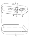
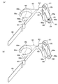
- FIG. 1 It is a disassembled perspective view of the fuel tank which shows the wave-cancelling plate fixing structure in the fuel tank which concerns on 1st Embodiment of this invention.
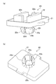
- A is a perspective view which shows the welding part of a clip
- (b) is a perspective view which shows the attachment part of a clip.
- (A) is the perspective view which shows the wave-dissipating board fixed to the clip
- (b) is the perspective view which looked at only the wave-dissipating board shown to (a) from the reverse side.
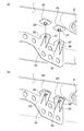
- (A) is a perspective view which shows the state which put the wave-dissipating plate on the clip welded to the inner wall of a fuel tank
- (b) is a perspective view which shows the state which fixed the wave-dissipating plate to the clip. It is the perspective view which showed the wave-cancelling board fixing structure in the fuel tank which concerns on 2nd Embodiment, and saw through the fuel tank from upper direction.
- (A) is a perspective view which shows the wave-dissipating plate fixed to the clip
- (b) is a perspective view which shows only the wave-dissipating plate shown to (a).
- a fuel tank 1 shown in FIG. 1 is made of resin, stores fuel such as gasoline therein, and is mounted on moving means such as an automobile, a motorcycle, and a ship.
- the fuel tank 1 is a type that is wide and thin in the vertical direction.
- the fuel tank 1 is formed of a thermoplastic resin including a barrier layer.
- FIG. 1 the structure of the upper part 1a and the lower part 1b at the time of dividing and cutting the fuel tank 1 into the upper and lower half in the thickness direction is shown.
- the wave tank fixing structure 10 in the fuel tank 1 two clips 20 and 20 are welded and fixed to the top surface of the inner wall of the upper portion 1a with a predetermined interval, and a wave canceling board 30 is attached to each of the fixed clips 20. It has a fixed structure.
- the pump mounting hole 2 for mounting a pump (not shown) for pumping fuel out of the tank is formed through the top surface of the inner wall of the upper portion 1a.
- Each clip 20 is welded and fixed in the vicinity of the pump mounting hole 2. Considering the fixing work of the wave eliminating plate 30, it is preferable to fix each clip 20 in the vicinity of the pump mounting hole 2.
- Each clip 20 is formed of a resin material.
- the resin material of the clip 20 may be any material as long as it can be welded to the fuel tank 1, but in this embodiment, the same material as that of the fuel tank 1 is used.
- each clip 20 includes a welded portion 22 that protrudes from one surface of a thin, rectangular parallelepiped base portion 21, and a base portion 21 that is opposite to the surface from which the welded portion 22 protrudes. It has the structure which has the attaching part 23 which protruded from the other surface.
- the welded portion 22 is composed of two key-shaped protrusions 22a and 22b.
- the protruding welded portion 22 is heated and welded to the top surface of the inner wall of the upper portion 1a (see FIG. 1).
- the mounting portion 23 has a plurality of (four in this example) locking claws 23a to 23d that protrude from the other surface of the base 21 in a circumferentially independent manner.
- Each of the locking claws 23a to 23d has a constricted shape having elasticity.
- each of the locking claws 23a to 23d is reduced in diameter toward the center of the circumference.
- each of the locking claws 23a to 23d having a reduced diameter expands to the outer peripheral side by an elastic force and returns to the original state.
- Each clip 20 is welded to a predetermined position on the inner wall of the fuel tank 1 as shown in FIG. 1 when the fuel tank 1 is formed, or a robot mechanism (not shown) after the fuel tank 1 is formed. Then, the clip 20 is inserted from the pump mounting hole 2 and welded at a predetermined position.
- the wave canceling plate 30 is a plate-like member that suppresses the ripple of fuel in the fuel tank 1.
- FIG. 3A shows a state in which the wave canceling plate 30 is attached and fixed to the clip 20.
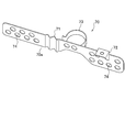
- the wave-dissipating plate 30 includes a first shape portion 31 having a large height dimension, a second shape portion 32 having a small height dimension, and attachment fixing portions 36 and 36.
- the wave eliminating plate 30 is made of resin and is integrally formed.
- the first shape portion 31 is a portion that is attached to the clip 20 with attachment fixing portions 36, 36 at the top.
- the 2nd shape part 32 is formed with the same board thickness as the 1st shape part 31, and is bent the predetermined angle to the one surface side.
- a plurality of penetrating round holes 33 are formed in both the first shape portion 31 and the second shape portion 32.
- the plurality of round holes 33 are for suppressing the undulation of the fuel by allowing a predetermined amount of the fuel to pass through when the fuel oscillates as the fuel tank 1 provided with the wave-cancelling plate 30 sways. is there.
- the mounting / fixing portion 36 includes a flat portion 36b straddling two support portions 36a and 36a that are vertically provided on the other surface of the first shape portion 31.
- a penetrating locking hole 37 is formed in the center of the flat portion 36b.
- the flat portion 36 is located above the upper end of the first shape portion 31.
- the locking hole 37 has a diameter slightly smaller than the maximum outer peripheral diameter of the locking claws 23a to 23d arranged in the circumferential shape of the clip 20.
- two clips 20 are welded to a predetermined position in the vicinity of the pump mounting hole 2 on the inner wall of the fuel tank 1.
- a wave-dissipating plate 30 is inserted into the fuel tank 1 from the pump mounting hole 2, and as shown in FIG. 4 (a), on the tip side of the locking claws 23a to 23d of the mounting portion 23 of each clip 20.
- the locking holes 37 of the mounting fixing portions 36 of the wave eliminating plate 30 are aligned.
- the mounting fixing portion 36 is fixed to the mounting portion 23, so that the wave canceling plate 30 is fixed to the clip 20 welded to the inner wall of the fuel tank 1. Accordingly, the wave canceling plate 30 is disposed at a predetermined position in the fuel tank 1.
- the wave canceling plate fixing structure 10 in the fuel tank 1 of the first embodiment is fixed inside the resin fuel tank 1 and the wave canceling plate 30 that suppresses the undulation of the fuel, and the fuel tank 1. It is set as the structure provided with the resin-made at least 2 clip 20 which has the welding part 22 welded and fixed to the inner wall of this, and the attaching part 23 to which the wave-cancelling board 30 is attached.
- the clip 20 is welded and fixed in advance to a predetermined position on the inner wall of the fuel tank 1, and the wave-dissipating plate 30 is inserted into the fuel tank 1 and attached and fixed to the clip 20.
- the wave canceling plate 30 can be easily fixed to a predetermined position in the fuel tank 1 with high accuracy.
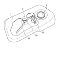
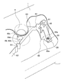
- FIG. 5 is a perspective view showing a configuration in which the fuel tank 1 is seen through from above.
- the above-described one clip 20 is welded and fixed at a predetermined position on the bottom surface in the fuel tank 1, and this fixed clip 20 and the fuel tank 1 are erected.
- a wave-dissipating plate 60 is attached and fixed to both the columnar portions 4.
- the columnar part 4 is a columnar part connected to the bottom surface and the top surface of the fuel tank 1.
- the shape of the columnar part 4 is not particularly limited, but in this embodiment, the flat cross section is circular.
- the columnar portion 4 can improve the deformation resistance and strength of the fuel tank 1.
- the “columnar portion” in the claims does not necessarily need to connect the bottom surface and the top surface, and may be a columnar portion standing from the inner surface of the fuel tank 1.
- the clip 20 is preferably positioned in the vicinity of the pump mounting hole 2 on the bottom surface of the fuel tank 1 in order to make it easy to attach the wave-dissipating plate 60 as in the first embodiment.
- the wave-dissipating plate 60 has a configuration shown in FIGS. 6 (a) and 6 (b).
- FIG. 6A shows a state where the wave canceling plate 60 is attached and fixed to the clip 20, and
- FIG. 6B shows only the wave canceling plate 60 shown in FIG.
- the wave canceling plate 60 includes a first shape portion 61, a second shape portion 62, a first flexible portion 63, a second flexible portion 64, an attachment fixing portion 66, and an engaging portion 69. Configured.
- the first shape portion 61 has a plate shape, and an attachment fixing portion 66 is integrally formed at the lower end on one surface side. A plurality of penetrating round holes 65 are formed in the first shape portion 61.
- the second shape portion 62 extends from the upper end side of the first shape portion 61 to the side. The height dimension of the second shape portion 62 is smaller than the height dimension of the first shape portion 61.
- the first flexible portion 63 is formed in a wave shape at the boundary portion between the first and second shape portions 61 and 62.
- the second flexible portion 64 is formed in a wave shape near the center of the second shape portion 62.
- the attachment fixing portion 66 is attached and fixed to the attachment portion 23 of the clip 20 fixed to the bottom surface of the fuel tank 1.
- the attachment fixing portion 66 includes a flat surface portion 66b straddling two support portions 66a and 66a that are vertically provided on the other surface of the first shape portion 61.
- a penetrating locking hole 68 is formed in the center of the flat portion 66b.
- the attachment fixing portion 66 corresponds to an “attachment portion” to the attachment portion in the wave breaker plate described in the claims.
- the locking hole 68 is for fixing the first shape portion 61 of the wave-dissipating plate 60 to the clip 20. That is, the locking hole 68 is aligned with the distal end side of each of the locking claws 23a to 23d (see FIG. 4A), and the wave breaker plate 60 is pushed toward the base 21 of the clip 20, thereby 68 moves to the position where the locking claws 23a to 23d are constricted, and the constriction fits into the locking hole 68. As a result, the mounting fixing portion 66 of the wave-dissipating plate 60 is fixed to the mounting portion 23 of the clip 20, and the first shape portion 61 of the wave-dissipating plate 60 stands on the bottom surface of the fuel tank 1 via the clip 20. It has become.
- the engaging part 69 is a part engaged with the columnar part 4 of the fuel tank 1 as shown in FIG.
- the engaging portion 69 includes a first arm portion 69a and a second arm portion 69b that have a substantially arc shape in plan view, and folded portions 69c and 69d formed at the tips of the first arm portion 69a and the second arm portion 69b, respectively. It consists of
- the first arm portion 69 a protrudes from the other surface of the second shape portion 62 in an arc shape in plan view at the base end of the second shape portion 62.
- the curvature of the first arm portion 69 a is substantially equal to the curvature of the outer peripheral surface of the columnar portion 4.
- a folded portion 69c that is bent inward and folded back is formed.
- the second arm portion 69b protrudes from the other surface of the second shape portion 62 in an arc shape in plan view between the first arm portion 69a and the second flexible portion 64.
- the curvature of the second arm portion 69 b is substantially equal to the curvature of the outer peripheral surface of the columnar portion 4.
- the total length of the second arm portion 69b is shorter than the total length of the first arm portion 69a.
- a folded portion 69d that is bent inward and folded back is formed.
- the engaging portion 69 is not limited to the above-described configuration, and may be appropriately formed according to the positions of the clip 20 and the columnar portion 4 and the like.
- the distance between the folded portion 69 c and the folded portion 69 d is smaller than the outer diameter of the columnar portion 4. Therefore, when the columnar part 4 is inserted from the turned-back parts 69c and 69d, the first arm part 69a and the second arm part 69b are spread away from each other, but the restoring force of the first arm part 69a and the second arm part 69b. Thus, the columnar portion 4 is sandwiched and fixed. Moreover, since the outer peripheral surface of the columnar part 4 can be smoothly moved by providing the folding
- one clip 20 is welded to a predetermined position on the bottom surface near the pump mounting hole 2 in the fuel tank 1.
- the wave-dissipating plate 60 is inserted into the fuel tank 1 from the pump mounting hole 2. At this time, if the wave-dissipating plate 60 is difficult to enter from the pump mounting hole 2, the wave-dissipating plate 60 is inserted into the pump mounting hole 2 while the second shape portion 62 is bent by the first and second flexible portions 63 and 64. Insert it in an easy shape. After this insertion, the locking holes 68 of the mounting fixing portions 66 of the wave breaker plate 60 are aligned with the distal ends of the locking claws 23a to 23d (see FIG. 4A) of the mounting portion 23 of the clip 20.
- the locking holes 68 are fitted into the locking claws 23a to 23d, and the constriction of the locking claws 23a to 23d (see FIG. 2) is locked. Fits into the hole 68.
- the attachment fixing portion 66 is attached and fixed to the attachment portion 23, so that one end of the wave eliminating plate 60 is attached to the inner wall of the fuel tank 1 via the clip 20.
- the engaging portion 69 of the wave canceling plate 60 is engaged with the columnar portion 4 in the fuel tank 1 as shown in FIG.
- the wave canceling plate If the 60 first flexible portions 63 are extended and the second interval is adjusted to the first interval, the engaging portion 69 can be properly engaged with the columnar portion 4.
- the engagement portion 69 can be properly engaged with the columnar portion 4 by contracting the first flexible portion 63 and matching the second interval to the first interval. Can do.
- the mounting and fixing to the clip 20 by the mounting and fixing portion 66 and the engagement to the columnar portion 4 by the engaging portion 69 are performed from either. Also good.
- the wave-dissipating plate fixing structure 50 in the fuel tank 1 of the second embodiment is fixed inside the resin fuel tank 1 and the wave-dissipating plate 60 that suppresses the undulation of the fuel, and the fuel tank 1.
- a resin-made clip 20 having an attachment portion 23 to which an attachment fixing portion 66 on one end side of the wave-dissipating plate 60 is attached.
- the wave-dissipating plate 60 includes an engaging portion 69 that can engage with the columnar portion 4 standing in the fuel tank 1.
- the welding portion 22 of the clip 20 is welded and fixed at a predetermined position on the inner wall of the fuel tank 1. Thereafter, the wave canceling plate 60 is inserted into the fuel tank 1 from the pump mounting hole 2 of the fuel tank 1, and one mounting fixing portion 66 of the wave canceling plate 60 is fixed to the mounting portion 23 of the clip 20. The other engaging portion 69 is engaged with the columnar portion 4 in a fitted state.
- the mounting and fixing of the mounting fixing portion 66 on one end side of the wave canceling plate 60 to the clip 20 can be performed only by fitting. Further, the engagement of the engaging portion 69 of the wave eliminating plate 60 with the columnar portion 4 can be performed only by fitting. Therefore, the wave canceling plate 60 can be easily fixed and disposed at a predetermined position in the fuel tank 1 with high accuracy.
- the engaging portion 69 can be fitted using the columnar portion 4 provided for the purpose of improving deformation resistance and strength. Further, since the columnar portion 4 is connected to the bottom surface and the top surface of the fuel tank 1, the engaging portion 69 can be stably fixed.
- the wave canceling plate 60 is provided with first and second flexible portions 63 and 64. For this reason, the wave-dissipating plate 60 can be easily inserted from the pump mounting hole 2 by bending the wave-dissipating plate 60 into a shape that can be easily inserted from the pump mounting hole 2 having a narrow inlet at the first and second flexible portions 63 and 64.
- the wave canceling plate 60 is provided with a first flexible portion 63 between the attachment fixing portion 66 and the engaging portion 69. For this reason, the 1st space
- the wave-dissipating plate 60 described above may be a wave-dissipating plate 70 having one flexible portion 71 as shown in FIG.
- the wave eliminating plate 70 includes a main body portion 70 a provided with a flexible portion 71 in the middle thereof, an attachment fixing portion 72, and an engaging portion 73.
- the main body 70a has an elongated rectangular shape in which a plurality of penetrating round holes 74 are formed.
- the attachment fixing portion 71 is provided on one end side of the main body portion 70a.
- the engaging portion 73 is provided between the attachment fixing portion 72 and the flexible portion 71.
- the flexible portions are provided on both sides of the engaging portion 69, but the flexible portion 71 may be provided only on the distal end side of the engaging portion 73 as in the modified example. Further, although not specifically shown, a flexible portion may be provided only between the engaging portion 73 and the attachment fixing portion 72.
Abstract
Description
<第1実施形態の構成>
以下、本発明の第1実施形態を、図面を参照して説明する。図1に示す燃料タンク1は、樹脂製であり内部にガソリン等の燃料を貯留し、自動車やバイク並びに船舶等の移動手段に搭載される。燃料タンク1は、幅広で上下方向の厚みが薄型のタイプである。燃料タンク1はバリア層を含んだ熱可塑性樹脂で形成されている。図1には、燃料タンク1を、厚み方向に上下半分に分割切断した際のアッパー部1aとロワー部1bの構成を示している。 Embodiments of the present invention will be described below with reference to the drawings.
<Configuration of First Embodiment>
Hereinafter, a first embodiment of the present invention will be described with reference to the drawings. A
は反対の基部21の他面から突出した取付部23とを有する構造となっている。 Each
次に、燃料タンク1の内壁に波消し板30を取り付けて固定する手順を説明する。 <Procedure of First Embodiment>
Next, a procedure for attaching and fixing the wave-dissipating
以上説明したように、第1実施形態の燃料タンク1における波消し板固定構造10は、樹脂製の燃料タンク1の内部に固定され、燃料の波立ちを抑制する波消し板30と、燃料タンク1の内壁に溶着固定される溶着部22及び波消し板30が取り付けられる取付部23を有する樹脂製の少なくとも2つのクリップ20とを備える構成とした。 <Effects of First Embodiment>
As described above, the wave canceling
次に、本発明の第2実施形態を、図面を参照して説明する。図5は燃料タンク1を上方から透視した構成を示す斜視図である。 <Configuration of Second Embodiment>
Next, a second embodiment of the present invention will be described with reference to the drawings. FIG. 5 is a perspective view showing a configuration in which the
次に、燃料タンク1の内壁に波消し板60を取り付けて固定する際の手順を説明する。 <Procedure of Second Embodiment>
Next, a procedure for attaching and fixing the wave-dissipating
以上説明したように、第2実施形態の燃料タンク1における波消し板固定構造50は、樹脂製の燃料タンク1の内部に固定され、燃料の波立ちを抑制する波消し板60と、燃料タンク1の内壁に溶着固定される溶着部22及び波消し板60の一端側の取付固定部66が取り付けられる取付部23を有する樹脂製のクリップ20とを備える。更に、波消し板60が、燃料タンク1内に立設する柱状部4に係合可能な係合部69を備える構成とした。 <Effects of Second Embodiment>
As described above, the wave-dissipating
上述の波消し板60は、図8に示すように、1つの可撓部71を有する波消し板70としてもよい。この波消し板70は、その可撓部71が途中に設けられた本体部70aと、取付固定部72と、係合部73とから構成されている。本体部70aは、複数の貫通した丸穴74が形成された細長い長方形状を成す。取付固定部71は、本体部70aの一端側に設けられている。係合部73は、取付固定部72及び可撓部71の間に設けられている。 <Modification of Second Embodiment>
The wave-dissipating
2 ポンプ取付穴
4 柱状部
1a 燃料タンクのアッパー部
1b 燃料タンクのロワー
10,50 波消し板固定構造
20 クリップ
21 基部
22 溶着部
23 取付部
23a~23d 係止爪
30,60,70 波消し板
31,61 第1形状部
32,62 第2形状部
33,65,74 丸穴
36,66,72 取付固定部
36b,66b 平面部
37,68 係止穴
70a 本体部
63 第1可撓部
64 第2可撓部
69,73 係合部
71 可撓部 DESCRIPTION OF
Claims (4)
- 樹脂製の燃料タンクの内部に固定され、燃料の波立ちを抑制する波消し板と、
前記燃料タンクの内壁に溶着固定される溶着部及び前記波消し板が取り付けられる取付部を有するクリップと、を備えることを特徴とする燃料タンクにおける波消し板固定構造。 A baffle plate that is fixed inside the resin fuel tank and suppresses the undulation of the fuel,
A wave plate fixing structure in a fuel tank, comprising: a weld portion that is welded and fixed to an inner wall of the fuel tank; and a clip having an attachment portion to which the wave plate is attached. - 前記波消し板は、前記燃料タンクの内部に立設する柱状部に係合可能な係合部を備えることを特徴とする請求の範囲第1項に記載の燃料タンクにおける波消し板固定構造。 2. The wave vane plate fixing structure in a fuel tank according to claim 1, wherein the wave vane plate includes an engaging portion engageable with a columnar portion standing inside the fuel tank.
- 前記波消し板は、可撓性を有する可撓部を備えることを特徴とする請求の範囲第1項に記載の燃料タンクにおける波消し板固定構造。 2. The wave plate fixing structure in a fuel tank according to claim 1, wherein the wave plate includes a flexible portion having flexibility.
- 前記波消し板は、前記取付部への取付部分と前記燃料タンクの内部に立設する柱状部に係合可能な係合部とを備え、
前記可撓部は、前記取付部分と前記係合部との間に形成されていることを特徴とする請求の範囲第3項に記載の燃料タンクにおける波消し板固定構造。 The wave-dissipating plate includes an attachment portion to the attachment portion and an engagement portion engageable with a columnar portion standing inside the fuel tank,
4. The wave vane plate fixing structure in a fuel tank according to claim 3, wherein the flexible portion is formed between the attachment portion and the engaging portion.
Priority Applications (4)
| Application Number | Priority Date | Filing Date | Title |
|---|---|---|---|
| CN201480047056.0A CN105492233B (en) | 2013-11-01 | 2014-10-07 | The fluctuation of fuel tank eliminates board fixing structure |
| MX2016002635A MX2016002635A (en) | 2013-11-01 | 2014-10-07 | Wave-eliminating plate securing structure in fuel tank. |
| US14/912,670 US9751400B2 (en) | 2013-11-01 | 2014-10-07 | Wave-eliminating plate securing structure in fuel tank |
| BR112016004224-7A BR112016004224B1 (en) | 2013-11-01 | 2014-10-07 | PROTECTION STRUCTURE OF WAVE DISPOSAL PLATE IN FUEL TANK |
Applications Claiming Priority (2)
| Application Number | Priority Date | Filing Date | Title |
|---|---|---|---|
| JP2013228642A JP6235869B2 (en) | 2013-11-01 | 2013-11-01 | Wave plate fixing structure in fuel tank |
| JP2013-228642 | 2013-11-01 |
Publications (1)
| Publication Number | Publication Date |
|---|---|
| WO2015064315A1 true WO2015064315A1 (en) | 2015-05-07 |
Family
ID=53003926
Family Applications (1)
| Application Number | Title | Priority Date | Filing Date |
|---|---|---|---|
| PCT/JP2014/076769 WO2015064315A1 (en) | 2013-11-01 | 2014-10-07 | Wave-eliminating plate securing structure in fuel tank |
Country Status (6)
| Country | Link |
|---|---|
| US (1) | US9751400B2 (en) |
| JP (1) | JP6235869B2 (en) |
| CN (1) | CN105492233B (en) |
| BR (1) | BR112016004224B1 (en) |
| MX (1) | MX2016002635A (en) |
| WO (1) | WO2015064315A1 (en) |
Cited By (1)
| Publication number | Priority date | Publication date | Assignee | Title |
|---|---|---|---|---|
| WO2018079209A1 (en) * | 2016-10-27 | 2018-05-03 | 八千代工業株式会社 | Mounting structure for integrated component of fuel tank |
Families Citing this family (9)
| Publication number | Priority date | Publication date | Assignee | Title |
|---|---|---|---|---|
| KR101738258B1 (en) * | 2015-09-23 | 2017-05-29 | 주식회사 동희산업 | Assembly Baffle for Plastic Fuel Tank |
| CN105522914B (en) * | 2015-12-22 | 2017-12-12 | 芜湖顺荣汽车部件有限公司 | Fuel tank built-in part |
| JP6923418B2 (en) * | 2017-10-26 | 2021-08-18 | トヨタ自動車株式会社 | Fuel tank |
| KR101994268B1 (en) | 2017-12-19 | 2019-06-28 | (주)동희산업 | Baffle assemblabe with supporter |
| WO2019163336A1 (en) * | 2018-02-23 | 2019-08-29 | 八千代工業株式会社 | Fuel tank |
| CN109973254B (en) * | 2019-01-24 | 2020-06-05 | 中氢新能技术有限公司 | Flameless combustion methanol fuel supply device |
| LU500624B1 (en) * | 2021-09-06 | 2023-03-06 | Plastic Omnium Advanced Innovation & Res | Fitting for motor vehicle tank |
| LU500622B1 (en) * | 2021-09-06 | 2023-03-06 | Plastic Omnium Advanced Innovation & Res | Fitting for a motor vehicle tank |
| LU500623B1 (en) * | 2021-09-06 | 2023-03-06 | Plastic Omnium Advanced Innovation & Res | Fitting for motor vehicle tank |
Citations (8)
| Publication number | Priority date | Publication date | Assignee | Title |
|---|---|---|---|---|
| JPH02112132U (en) * | 1989-02-28 | 1990-09-07 | ||
| JP2005170084A (en) * | 2003-12-08 | 2005-06-30 | Piolax Inc | Noise eliminator for fuel tank |
| JP2006207446A (en) * | 2005-01-27 | 2006-08-10 | Toyota Motor Corp | Separator structure in fuel tank |
| JP2006264580A (en) * | 2005-03-25 | 2006-10-05 | Piolax Inc | Baffle plate |
| WO2007099691A1 (en) * | 2006-02-28 | 2007-09-07 | Nifco Inc. | Sound muffling device and its mounting method |
| JP2007237843A (en) * | 2006-03-07 | 2007-09-20 | Fts:Kk | Fuel tank |
| JP2009132365A (en) * | 2007-11-05 | 2009-06-18 | Honda Motor Co Ltd | Fixing structure for resin tank built-in part |
| JP2013220704A (en) * | 2012-04-16 | 2013-10-28 | Yachiyo Industry Co Ltd | Fixing structure for wave suppressor member, and fixing method for wave suppressor member |
Family Cites Families (18)
| Publication number | Priority date | Publication date | Assignee | Title |
|---|---|---|---|---|
| US4898424A (en) | 1988-07-08 | 1990-02-06 | Fisher Dynamics Corporation | Linear seat recliner |
| JPH0234443U (en) * | 1988-08-29 | 1990-03-05 | ||
| US5678826A (en) * | 1993-08-23 | 1997-10-21 | Orbseal, Inc. | Retractable retainer and sealant assembly method |
| US5506025A (en) * | 1995-01-09 | 1996-04-09 | Sika Corporation | Expandable baffle apparatus |
| US6146565A (en) * | 1998-07-15 | 2000-11-14 | Noble Polymers, L.L.C. | Method of forming a heat expandable acoustic baffle |
| US6138859A (en) * | 1999-06-08 | 2000-10-31 | Delphi Technologies, Inc. | Fuel tank assembly |
| US6413611B1 (en) * | 2000-05-01 | 2002-07-02 | Sika Corporation | Baffle and reinforcement assembly |
| US6820923B1 (en) * | 2000-08-03 | 2004-11-23 | L&L Products | Sound absorption system for automotive vehicles |
| US20050082111A1 (en) * | 2003-10-18 | 2005-04-21 | Sika Technology Ag | Acoustic baffle |
| EP2109563A1 (en) * | 2006-12-28 | 2009-10-21 | Henkel Kommanditgesellschaft auf Aktien | Acoustic baffle |
| CN102083655A (en) * | 2008-03-07 | 2011-06-01 | 汉高公司 | Acoustic baffle assembly |
| US8449701B2 (en) * | 2008-11-26 | 2013-05-28 | Dow Global Technologies Llc | Acoustic baffle members and methods for applying acoustic baffles in cavities |
| JP2010168036A (en) * | 2008-12-26 | 2010-08-05 | Nitto Denko Corp | Shield plate and vehicle structure provided with the shield plate |
| US9050889B2 (en) | 2009-09-18 | 2015-06-09 | Ti Automotive Technology Center Gmbh | Fuel tank support |
| JP5331142B2 (en) * | 2011-03-01 | 2013-10-30 | 八千代工業株式会社 | Mounting structure of buffer member in fuel tank |
| WO2013142145A1 (en) * | 2012-03-20 | 2013-09-26 | Zephyros, Inc. | Baffle assembly |
| KR20150021927A (en) * | 2012-06-08 | 2015-03-03 | 제피로스, 인크. | Baffle with expanding material |
| US8991637B2 (en) * | 2013-01-15 | 2015-03-31 | Ti Automotive Technology Center Gmbh | Molded reservoir support structure coupling |
-
2013
- 2013-11-01 JP JP2013228642A patent/JP6235869B2/en active Active
-
2014
- 2014-10-07 WO PCT/JP2014/076769 patent/WO2015064315A1/en active Application Filing
- 2014-10-07 CN CN201480047056.0A patent/CN105492233B/en active Active
- 2014-10-07 MX MX2016002635A patent/MX2016002635A/en active IP Right Grant
- 2014-10-07 US US14/912,670 patent/US9751400B2/en active Active
- 2014-10-07 BR BR112016004224-7A patent/BR112016004224B1/en active IP Right Grant
Patent Citations (8)
| Publication number | Priority date | Publication date | Assignee | Title |
|---|---|---|---|---|
| JPH02112132U (en) * | 1989-02-28 | 1990-09-07 | ||
| JP2005170084A (en) * | 2003-12-08 | 2005-06-30 | Piolax Inc | Noise eliminator for fuel tank |
| JP2006207446A (en) * | 2005-01-27 | 2006-08-10 | Toyota Motor Corp | Separator structure in fuel tank |
| JP2006264580A (en) * | 2005-03-25 | 2006-10-05 | Piolax Inc | Baffle plate |
| WO2007099691A1 (en) * | 2006-02-28 | 2007-09-07 | Nifco Inc. | Sound muffling device and its mounting method |
| JP2007237843A (en) * | 2006-03-07 | 2007-09-20 | Fts:Kk | Fuel tank |
| JP2009132365A (en) * | 2007-11-05 | 2009-06-18 | Honda Motor Co Ltd | Fixing structure for resin tank built-in part |
| JP2013220704A (en) * | 2012-04-16 | 2013-10-28 | Yachiyo Industry Co Ltd | Fixing structure for wave suppressor member, and fixing method for wave suppressor member |
Cited By (3)
| Publication number | Priority date | Publication date | Assignee | Title |
|---|---|---|---|---|
| WO2018079209A1 (en) * | 2016-10-27 | 2018-05-03 | 八千代工業株式会社 | Mounting structure for integrated component of fuel tank |
| JPWO2018079209A1 (en) * | 2016-10-27 | 2019-07-11 | 八千代工業株式会社 | Mounting structure for internal parts of fuel tank |
| US10569644B2 (en) | 2016-10-27 | 2020-02-25 | Yachiyo Industry Co., Ltd. | Mounting structure for integrated component of fuel tank |
Also Published As
| Publication number | Publication date |
|---|---|
| MX2016002635A (en) | 2016-10-26 |
| CN105492233A (en) | 2016-04-13 |
| JP6235869B2 (en) | 2017-11-22 |
| BR112016004224B1 (en) | 2022-01-04 |
| BR112016004224A2 (en) | 2017-08-01 |
| US20160200192A1 (en) | 2016-07-14 |
| CN105492233B (en) | 2017-12-26 |
| JP2015085915A (en) | 2015-05-07 |
| US9751400B2 (en) | 2017-09-05 |
Similar Documents
| Publication | Publication Date | Title |
|---|---|---|
| WO2015064315A1 (en) | Wave-eliminating plate securing structure in fuel tank | |
| US10006565B2 (en) | Fuel supply apparatus | |
| JP2017055510A (en) | Wire Harness | |
| US9994169B2 (en) | Wire harness | |
| JP2013067251A (en) | Battery mounting structure | |
| WO2014203683A1 (en) | Airbag device | |
| JP2012109678A (en) | Clip | |
| JP5242536B2 (en) | clip | |
| JP2014241666A (en) | Corrugated-tube clamp and wire harness with corrugated-tube clamp | |
| JP5606822B2 (en) | Bolt fitting | |
| JP6298696B2 (en) | Detachment structure of built-in parts in fuel tank | |
| JP5459043B2 (en) | Wire clamp | |
| US9969347B2 (en) | Airbag device | |
| JP4812663B2 (en) | clip | |
| JP2013082281A5 (en) | ||
| JP4915707B2 (en) | Clamp | |
| JP2016119785A (en) | Wire with protective member, and protective member | |
| JP2011205773A (en) | Clip for holding wire harness | |
| JP7277914B2 (en) | ferrite clamp fixture | |
| JP5853482B2 (en) | Grommet | |
| JP6747184B2 (en) | Hose mounting tube | |
| JP4945724B2 (en) | Mounting member for LCD panel | |
| JP6562696B2 (en) | Bracket for vibration isolator | |
| JP2014043170A (en) | Bracket mounting device for heat exchanger | |
| JP2005280428A (en) | Bracket for retaining tube |
Legal Events
| Date | Code | Title | Description |
|---|---|---|---|
| WWE | Wipo information: entry into national phase |
Ref document number: 201480047056.0 Country of ref document: CN |
|
| 121 | Ep: the epo has been informed by wipo that ep was designated in this application |
Ref document number: 14857872 Country of ref document: EP Kind code of ref document: A1 |
|
| WWE | Wipo information: entry into national phase |
Ref document number: IDP00201600983 Country of ref document: ID |
|
| WWE | Wipo information: entry into national phase |
Ref document number: 14912670 Country of ref document: US |
|
| WWE | Wipo information: entry into national phase |
Ref document number: MX/A/2016/002635 Country of ref document: MX |
|
| REG | Reference to national code |
Ref country code: BR Ref legal event code: B01A Ref document number: 112016004224 Country of ref document: BR |
|
| NENP | Non-entry into the national phase |
Ref country code: DE |
|
| 122 | Ep: pct application non-entry in european phase |
Ref document number: 14857872 Country of ref document: EP Kind code of ref document: A1 |
|
| ENP | Entry into the national phase |
Ref document number: 112016004224 Country of ref document: BR Kind code of ref document: A2 Effective date: 20160226 |