WO2015060040A1 - 距離測定システム - Google Patents
距離測定システム Download PDFInfo
- Publication number
- WO2015060040A1 WO2015060040A1 PCT/JP2014/074430 JP2014074430W WO2015060040A1 WO 2015060040 A1 WO2015060040 A1 WO 2015060040A1 JP 2014074430 W JP2014074430 W JP 2014074430W WO 2015060040 A1 WO2015060040 A1 WO 2015060040A1
- Authority
- WO
- WIPO (PCT)
- Prior art keywords
- distance
- distance measurement
- transmission
- reception
- child
- Prior art date
- Legal status (The legal status is an assumption and is not a legal conclusion. Google has not performed a legal analysis and makes no representation as to the accuracy of the status listed.)
- Ceased
Links
Images






Classifications
-
- B—PERFORMING OPERATIONS; TRANSPORTING
- B60—VEHICLES IN GENERAL
- B60R—VEHICLES, VEHICLE FITTINGS, OR VEHICLE PARTS, NOT OTHERWISE PROVIDED FOR
- B60R25/00—Fittings or systems for preventing or indicating unauthorised use or theft of vehicles
- B60R25/20—Means to switch the anti-theft system on or off
- B60R25/24—Means to switch the anti-theft system on or off using electronic identifiers containing a code not memorised by the user
-
- G—PHYSICS
- G01—MEASURING; TESTING
- G01S—RADIO DIRECTION-FINDING; RADIO NAVIGATION; DETERMINING DISTANCE OR VELOCITY BY USE OF RADIO WAVES; LOCATING OR PRESENCE-DETECTING BY USE OF THE REFLECTION OR RERADIATION OF RADIO WAVES; ANALOGOUS ARRANGEMENTS USING OTHER WAVES
- G01S13/00—Systems using the reflection or reradiation of radio waves, e.g. radar systems; Analogous systems using reflection or reradiation of waves whose nature or wavelength is irrelevant or unspecified
- G01S13/74—Systems using reradiation of radio waves, e.g. secondary radar systems; Analogous systems
- G01S13/76—Systems using reradiation of radio waves, e.g. secondary radar systems; Analogous systems wherein pulse-type signals are transmitted
-
- G—PHYSICS
- G01—MEASURING; TESTING
- G01S—RADIO DIRECTION-FINDING; RADIO NAVIGATION; DETERMINING DISTANCE OR VELOCITY BY USE OF RADIO WAVES; LOCATING OR PRESENCE-DETECTING BY USE OF THE REFLECTION OR RERADIATION OF RADIO WAVES; ANALOGOUS ARRANGEMENTS USING OTHER WAVES
- G01S15/00—Systems using the reflection or reradiation of acoustic waves, e.g. sonar systems
- G01S15/74—Systems using reradiation of acoustic waves, e.g. IFF, i.e. identification of friend or foe
Definitions
- the present invention relates to a distance measurement system that performs a predetermined function based on a distance between a mobile terminal and a transceiver, which is suitable for a smart key system or the like, and in particular, a distance measurement signal used in calculating the distance is invalid.
- the present invention relates to a distance measurement system that can safely execute a predetermined function even when it is acquired and transmitted.
- Smart key systems are widespread mainly in automobiles.
- the user can unlock and lock the key without inserting it into the keyhole of the vehicle door.
- authentication is performed by communication between a portable device of a user and an in-vehicle transceiver.
- the door lock is unlocked.
- the radio signal range of the transceiver is limited to a short distance of about 2 m by using a dedicated radio device of 125 kHz or 300 MHz. This solves a security problem such as when the user is away from the vehicle, the door is unlocked and a third party can enter the vehicle.
- Patent Document 1 effectively suppresses damage caused by unauthorized unlocking of the door lock by providing a mechanism that corrects the clock error between the portable device of the authorized owner and the vehicle. is doing.
- Patent Document 2 a portable terminal such as a smartphone can be used as a portable device of the smart key system.
- Smartphones are equipped with wireless devices such as bluetooth (registered trademark) and Wi-Fi (registered trademark).
- wireless devices such as bluetooth (registered trademark) and Wi-Fi (registered trademark).
- Bluetooth registered trademark
- Wi-Fi registered trademark
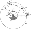
- FIG. 1 is a diagram for schematically explaining the procedure in Patent Document 2.
- FIG. FIG. 1 shows a distance measurement system including a transceiver 100 installed in a car C1 and a portable device 101 possessed by a user U1 of the car C1, and schematically shows steps (1) to (3). It is shown.
- the procedure (1) when the portable device 101 that has moved with the user U1 enters the wireless communicable range R10, as shown by the bidirectional arrow A1, the transceiver 100 and the portable device 101 Authentication is performed by exchanging a preset key.
- step (2) distance measurement is started between the transceiver 100 and the portable device 101 by transmission and reception of sound waves as indicated by the bidirectional arrow A2, and the transceiver 100 Continuously estimates the distance between the user U1 and the vehicle C1 (distance between the portable device 101 and the transceiver 100) based on the transmission / reception time of the sound wave.
- the user U1 moves in the range R10 along the trajectory P1 together with the portable device 101, and during this time, the distance measurement according to the procedure (2) is continuously performed. (Note that the user U1 who is moving is omitted in FIG. 1)
- procedure (3) when the user U1 approaches the vehicle C1 and reaches the range R11 in which the distance measurement result is equal to or less than the threshold, the transceiver 100 unlocks the door lock of the automobile C1.
- a general-purpose portable device 101 such as a smartphone, as in the case of using a dedicated device.
- Patent Document 2 a smart key system is realized by using authentication by radio wave communication and ranging technology using sound waves.
- the sound waves used for distance measurement can be easily recorded and reproduced by a recorder or the like, there is a problem that the door lock is unlocked illegally by the following procedure.
- FIG. 2 is a diagram for schematically explaining the illegal procedure.
- the transceiver 100 installed in the car C1 and the portable device 101 of the user U1 are the same as those in FIG. 1, and the steps (1) and (2) are the same as those in FIG. Is implemented in the same manner as in FIG.
- an unauthorized user U2 instead of the procedure (3) being performed by the authorized user U1 as shown in FIG. 1, an unauthorized user U2 such as a malicious third party uses the unauthorized terminal 102 to perform an unauthorized procedure.
- (4), (5), (6) are implemented.
- the authorized user U1 enters the authentication range R10 together with the portable device 101 in the procedure (1) and authentication is performed, and ranging by sound waves is started and continued as in the procedure (2). Is done.
- the procedure (2) if the authorized user U1 reaches the vehicle C1 promptly, the procedure (3) is executed safely as in FIG. 1, but in FIG. In the middle of P1, it is assumed that the procedure (3) has not been reached immediately because, for example, the user has stopped and started talking.
- step (4) the unauthorized terminal 102 illegally records the sound waves transmitted and received between the transceiver 100 and the legitimate portable device 101 as the two-way arrow A2 in step (2), in the form of eavesdropping. To do. That is, the sound wave transmitted from the legitimate portable device 101 is illegally recorded as indicated by the arrow A3, and the sound wave transmitted from the transceiver 100 is illegally recorded as indicated by the arrow A4.
- the unauthorized terminal 102 is used by a technique such as identifying a sound wave periodically received in the unauthorized recording and / or a sound analysis method appropriately adding the judgment of the unauthorized user U2 itself. Identifies illegally the sound wave transmitted by the legitimate portable device 101 and the sound wave transmitted by the transceiver 100.
- step (5) while the unauthorized user U2 moves along the locus P2 with the unauthorized terminal 102, the unauthorized terminal 102 transmits the transmitted sound wave of the portable device 101 that has been unauthorizedly recorded.
- the transceiver 100 itself is a two-way arrow. Although it intends to perform distance measurement at the time of sound wave transmission / reception with the regular mobile device 101 shown in A2, it is actually between the unauthorized terminal 102 as shown in the two-way arrow A5. The distance measurement between the unauthorized terminal 102 and the transmitter / receiver 100 is performed based on the transmission / reception time of the sound wave.
- the unauthorized terminal 102 can impersonate the regular portable device 101 with respect to the distance measuring process with respect to the transmitter / receiver 100 by using the illegally recorded sound wave. At this time, the unauthorized terminal 102 illegally transmits the sound wave of the portable device 101 that has been illegally recorded.
- the transceiver 100 executes unauthorized unlocking of the vehicle C1 against the unauthorized terminal 102 of the unauthorized user U2 that has approached. May end up.
- the transmitter / receiver 100 that uses an unauthorized transmission / reception time even if the unauthorized terminal 102 does not necessarily reach the range R11. For example, it may cause an unexpected malfunction.
- FIG. 2 an example in which the transmission / reception time (of which reception time) in the transceiver 100 is incorrect has been described, but the transmission / reception of sound waves is bidirectional between the transceiver 100 and the regular portable device 101.
- the transmission / reception time (of which the reception time) in the portable device 101 becomes invalid.
- an unexpected malfunction may occur.
- FIG. 13 is a diagram for explaining the problem.
- FIG. 13 shows a case where there is no illegal sound wave transmission / reception in (1) and a case where the problem is caused in (2).
- (1) sound waves are correctly transmitted and received between the transceiver 100 and the portable device 101. That is, when the transmitter / receiver 100 transmits the normal sound wave A toward the portable device 101 as shown in [1], the portable device 101 transmits and receives the reception time of the sound wave A wirelessly as shown in [2]. Notify machine 100. Further, as shown in [3], the portable device 101 transmits the regular sound wave B toward the transceiver 100.
- the transmitter 100 acquires the reception times of the regular sound waves A and B transmitted in both directions, and correctly calculates the distance from the portable device 101.
- the fraud described with reference to FIG. 2 is that the sound wave B is illegally transmitted by the unauthorized terminal 102.
- FIG. 13 (2) shows a situation where both sound waves A and B are illegally transmitted.
- both of the sound waves A and B transmitted in both directions are illegally transmitted, and the transmitter 100 acquires the illegal reception time of both, and calculates the distance. Therefore, the distance is incorrect. Similarly, there may be a situation in which only the sound wave A is illegally transmitted. In this case, an illegal distance is calculated.
- an object of the present invention is to provide a distance measuring system that can function safely even if there is an unauthorized signal transmission.
- the present invention is a distance measurement system that includes a mobile terminal and a transceiver, measures a distance between the two, and executes a predetermined function based on the distance,
- a ranging signal transmission / reception unit that continuously transmits and receives a ranging signal and obtains its transmission / reception time is included, and the portable terminal or the transmitter / receiver determines the distance between the two based on the transmission / reception time of the ranging signal.
- a distance calculation unit for calculating, and the portable terminal or the transceiver includes a function execution unit for executing a predetermined function based on the calculated distance, and the transmission / reception between the portable terminal and the transceiver is performed.
- the distance signal is selected from a plurality of types of signals at each transmission / reception, and the function execution unit receives the selected distance measurement signal and the calculated distance is equal to or less than a predetermined threshold. In the case where it is determined that the continued satisfies a predetermined condition, and executes the predetermined function.
- the distance measurement signal is selected from a plurality of times at each transmission / reception, and the predetermined function is not executed unless the selected distance measurement signal is continuously received. Therefore, even if the ranging signal is illegally acquired and illegally transmitted, the predetermined function is safely executed because it is unlikely that the distance measurement signal continuously matches that selected at each time.
- FIG. It is a figure for showing the procedure in patent documents 2 typically. It is a figure for demonstrating typically the unauthorized procedure with respect to the procedure of patent document 2.
- FIG. It is a figure for demonstrating the structure outline
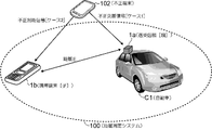
- FIG. 3 is a diagram for explaining the outline of the configuration of the distance measurement system 100 of the present invention.
- the distance measurement system 100 includes a transceiver 1a and a portable terminal 1b.
- the place where the transceiver 1a is installed in the automobile C1 is conceptually illustrated as an example.
- the distance measurement system 100 can be used for a smart key system.
- the transceiver 1a may also be installed in a bicycle, an office or home door, a personal computer (PC), or the like other than a car.
- a smart phone or a mobile phone can be used for the mobile terminal 1b.
- the transceiver 1a is appropriately abbreviated as the parent 1a as a parent machine
- 1b is abbreviated as a child 1b as a child device.
- the parent 1a is fixed at a fixed position and the child 1b is carried by the user. Or both may move.
- the distance E between them is sequentially calculated in time series as shown in FIG.
- the parent 1a performs a predetermined function based on the calculated distance E.
- a distance measurement signal is transmitted and received between the parent 1a and 1b.
- the distance measurement signal transmitted and received between the parent and child 1a, 1b is identified properly while eliminating the influence of the unauthorized terminal 102 that illegally records, acquires and transmits the distance measurement signal. It is possible to calculate E and safely execute a predetermined function based on the distance E.
- the unauthorized terminal 102 is illustrated in FIG. 3 to assist in understanding that the influence is excluded, the unauthorized terminal 102 is not included in the distance measurement system 100. (The same applies to FIGS. 4 and 10 described later.)
- the fraud performed by the fraudulent terminal 102 is fraud shown as [Case 1] in FIG. 3, that is, fraudulent transmission of a ranging signal received by the transceiver 1a (the fraud explained in FIG. 2).
- the countermeasure for the [Case 1] according to the present invention will be mainly described.
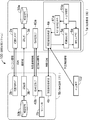
- FIG. 4 is a functional block diagram of the transceiver 1a and the portable terminal 1b constituting the distance measuring system 100.
- the transceiver 1a includes a range determination unit 2a, an authentication unit 3a, a key management unit 30a, an information transmission / reception unit 40a, a distance measurement signal transmission / reception unit 4a, a distance measurement signal setting unit 41a, a distance calculation unit 5a, an fraud determination unit 51a, and a function execution.
- a portion 6a is provided.
- the portable terminal 1b includes a range determination unit 2b, an authentication unit 3b, a key management unit 30b, an information transmission / reception unit 40b, a distance measurement signal transmission / reception unit 4b, and a sensor unit 7b.
- the range determination units 2a and 2b periodically transmit a beacon signal from the parent 1a side (range determination unit 2a) to the child 1b side (range determination unit 2b). On the child 1b side, when receiving the beacon signal, the child 1b side responds to the parent 1a side.
- each functional unit if the same or corresponding processing is performed between the parent and child 1a, 1b, as in the description of the range determination units 2a, 2b, “parent 1a By “side” and “child 1b side”, etc., “functional part Xa on parent 1a side” and “functional part Xb on child 1b side” are represented.
- X corresponds to 2, 3, 30, 4, 40.
- the authentication units 3a and 3b authenticate between the parent and child 1a and 1b wirelessly when it is confirmed that the parent and child 1a and 1b can communicate wirelessly by transmitting and responding to the beacon signal.
- the parent and child 1a and 1b set and manage their own key information in advance by the key management units 30a and 30b, respectively.
- the information transmission / reception units 40a and 40b transmit and receive information necessary for performing the distance calculation process, the fraud determination process, the predetermined function execution process, and the like according to the present invention between the parent and child 1a and 1b by radio.
- information on the distance measurement signal to be transmitted to the child 1b (configuration frequency, transmission timing, etc.) is notified, and from the child 1b side to the parent 1a side, the distance measurement signal in the child 1b
- other information is also sent and received.
- the ranging signal transmission / reception units 4a and 4b After completion of the authentication, the ranging signal is continuously transmitted and received in one direction or in both directions between the parent and child 1a and 1b, and the transmission / reception time of the ranging signal is recorded. To do.
- the ranging signal setting unit 41a sets the ranging signal to be transmitted / received (configuration frequency, transmission timing, etc.). The setting is also shared on the child 1b side via the information transmission / reception units 40a and 40b.
- the distance measurement signal transmission / reception units 4a and 4b continuously record the signal (if the distance measurement signal is a sound wave), record the signal.
- the distance measurement signal can be identified by the component frequency or the like to obtain the transmission / reception time.
- the transmission / reception of the distance measurement signal can be performed unidirectionally or bidirectionally. However, in the following description, the bidirectional signal will be basically assumed.
- an incorrect distance measurement signal coincides with an actually used one among the m types. Reduce the probability of that.
- the distance calculation unit 5a calculates the distance between the parent and child 1a, 1b based on the transmission / reception time of the distance measurement signal made between the distance measurement signal transmission / reception units 4a, 4b.
- the distance is also continuously calculated in time series.
- the distance calculation process is also referred to as a distance measurement process as appropriate.
- the fraud determination unit 51a analyzes the record of transmission / reception signals (recording if the distance measurement signal is a sound wave) in the distance measurement signal transmission / reception unit 4a in conjunction with the distance measurement processing of the distance calculation unit 5a, and performs the measurement. It is determined whether or not an unauthorized ranging signal is transmitted by the unauthorized terminal 102 toward the parent 1a near the time when the distance processing is performed. When it is determined that the fraud has occurred, the fraud determination unit 51a gives various instructions to the function execution unit 6a and / or the distance measurement signal setting unit 41a.
- the function execution unit 6a executes a predetermined function based on the distance calculated by the distance calculation unit 5a. If the parent 1a is installed in the automobile, the door of the automobile may be unlocked when the distance is less than or equal to the threshold, and the automobile door may be locked when the distance is greater than the threshold. Furthermore, the engine lock may be released / set in the same manner using another threshold value.
- the function execution unit 6a can release / lock the corresponding key even when the parent 1a is installed on a bicycle, an office or home door, a personal computer (PC), etc., by threshold determination similar to the above. .
- PC personal computer
- threshold determination similar to the above.
- screen lock control may be performed.
- predetermined functions for other purposes may be executed.
- the function execution unit 6a does not immediately execute the predetermined function when the distance calculated by the distance calculation unit 5a satisfies the threshold condition, but satisfies the threshold condition of the distance. Continuation is imposed as a condition for executing a predetermined function. In the present invention, by imposing the condition, the probability that the actually used out of m types of ranging signals and the unauthorized ranging signal will continue to decrease exponentially decreases, so that the illegal terminal 102 The influence of an illegal ranging signal can be eliminated.
- the function execution unit 6a receives an instruction after making the fraud determination from the fraud determination unit 51a, for example, sounds an alarm. To perform various functions.
- radio types sound waves, ultrasonic waves, and radio waves such as Wi-Fi (registered trademark) and Bluetooth (registered trademark) can be used, and each function unit may use a separate type of radio. In this case, there may be a functional unit that uses the same type of radio. In addition, each function unit may use another type of radio depending on the type of information to be handled.
- Other exchanges do not necessarily require the wireless signal to reach directly between the parent and child 1a, 1b, even via a server on a separate wired / wireless network via a base station such as 3G or LTE. Good.
- the distance measurement signal needs to reach directly between the parent and child 1a and 1b. Therefore, in order to first identify whether the direct reach is possible, the processing procedure of the present invention is divided into cases depending on whether the parent / child 1a, 1b is outside the wireless communication range or within the wireless communication range. To be implemented.
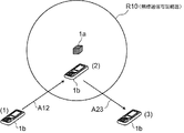
- FIG. 5 is a diagram for explaining the case classification of processing procedures depending on the inside and outside of the wireless communicable range.
- the radio communicable range R10 is shown centering on the parent 1a at the fixed position, and when the child 1b exists within the range R10, the radio directly reaches between the parent 1a and 1b. Communication and ranging are possible.
- (2) shows the case where the child 1b exists within the range R10
- (1) and (3) show the case where the child 1b exists outside the range R10, respectively. Based on this distinction, the following procedures are performed in each range.
- the parent 1a waits for the child 1b to enter the wireless communicable range, and constantly monitors whether the child 1b has entered the range. Specifically, the range determination unit 2a of the parent 1a transmits a beacon signal at a predetermined period and waits for a response from the child 1b. On the other hand, the range determination unit 2b of the child 1b continues to monitor whether or not a beacon signal has been received, and responds if received.
- FIG. 6 shows a processing procedure between the parent and child 1a and 1b after entering the wireless communicable range after being outside the wireless communication range.
- steps (S1) to (S4) are procedures in which authentication is performed when it is detected that the wireless communication range is entered as indicated by an arrow A12 in FIG.
- steps (S6) to (S11) after the start notification in step (S5) corresponds to a procedure within the wireless communicable range that is repeatedly performed so as to be surrounded by block B.
- step (S1) since the child 1b has moved into the range R10, the beacon signal transmitted by the parent 1a is received by the child 1b.
- step (S2) the child 1b sends a response signal to the parent 1a in response to the beacon signal.
- the child 1b knows that the child 1b exists within the range R10 by receiving the beacon signal, and can switch to processing within the wireless communicable range.
- the parent 1a knows that the child 1b exists in the range R10 by receiving the response signal, and can switch to the processing in the wireless communicable range.
- step (S3) the authentication unit 3a, 3b transmits key information from the child 1b side to the parent 1a side to perform authentication processing between the parent 1a, 1b, and in step (S4),
- the key information received from the child 1b is compared with the key information held by the parent 1a, and the parent 1a authenticates the child 1b.
- the key information is set in advance in the key management units 30a and 30b as described above. Note that, regarding the mode of transmission / reception of key information between the parent and child 1a and 1b, authentication may be performed by a method other than steps (S3) and (S4), for example, authentication is performed on the child 1b side, mutual authentication, etc. .
- step (S4) If the authentication of the step (S4) is successful, the start of the ranging process is notified from the parent 1a to the child 1b by the step (S5), and then the processing within the wireless communication possible range after the step (S6) Proceed to If the authentication in step (S4) fails, the process does not proceed to step (S5) and subsequent steps, and the process returns to the above (1. Outside the wireless communication range).
- the clock may be set between the parent and child 1a and 1b at the start notification of step (S5).
- the clock adjustment may be performed with accuracy necessary for distance measurement processing (details will be described later).
- step (S6) the ranging signal setting unit 41a sets the ranging signal to be transmitted / received by the ranging signal transmitting / receiving units 4a, 4b.
- step (S7) the setting is notified from the parent 1a to the child 1b so that the setting is shared between the parent 1a and 1b.
- step (S8) according to the shared setting, the distance measurement signal transmission / reception units 4a and 4b transmit and receive distance measurement signals, and record the transmission / reception times.
- step (S8) the child 1b further notifies the parent 1a of the recorded transmission / reception time.
- step (S9) the distance calculation unit 5a calculates the distance between the parent and child 1a, 1b at the time based on the transmission / reception times on both the parent 1a side and the child 1b side acquired by the ranging signal transmission / reception units 4a, 4b. calculate.
- step (S10) the fraud determination unit 51a determines whether or not an illegal ranging signal has been received during the distance calculation.
- step (S11) when the calculated distance satisfies a predetermined condition over a certain period, the function execution unit 6a executes a predetermined function (such as unlocking in the case of a smart key system). Also, in step (S11), when the fraud determination is made in the immediately preceding step (S10), the function execution unit 6a executes a predetermined function for dealing with the fraud.
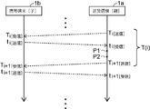
- a predetermined function such as unlocking in the case of a smart key system
- FIG. 7 is a diagram schematically showing transmission / reception and other repetitions of the distance measurement signal.
- the distance measurement signal is transmitted / received in both directions between the parent and child 1a, 1b is shown.
- the ranging signal may be transmitted and received in a single direction between the parent 1a and 1b.
- the interval T (i) is given as the interval between the time T i [transmission] transmitted by the parent 1a at the i-th time and the time T i + 1 [transmission] transmitted at the i + 1-th time.
- Transmission and reception processing of the ranging signal in step (S8) in iteration i-th in the case of bidirectional transmission and reception, as shown, the transmission of the ranging signal at time T i [Send] by the parent 1a, for the transmission It consists of reception at time T i [reception] by the child 1b, transmission of a ranging signal at time t i [transmission] by the child 1b, and reception at time t i [reception] by the parent 1a for the transmission.
- unidirectional transmission / reception only one of the processes shown in the figure is performed.
- Steps (S9), (S10), and (S11) are executed at time point P1, and steps (S6) and (S7) in the (i + 1) th iteration of block B are executed at time point P2.
- Time points P1 and P2 may be simultaneous.
- the interval T (i) is an interval of distance measurement signal transmission / reception by the distance measurement signal transmission / reception units 4a and 4b, and is an interval of distance measurement processing by the distance calculation unit 5a and fraud determination processing by the fraud determination unit 51a. It is also an interval for determining whether or not the function execution unit 6a executes the function. Note that the interval T (i) is notified to the child 1b side in step (S7), thereby enabling processing in which the parent and child 1a, 1b are aligned at the same timing.
- Both of the parent and child 1a and 1b may determine that they are out of the wireless communication range, and shift to the above processing (1. outside the wireless communication range). The determination may be performed independently on the parent 1a side and the child 1b side.
- FIG. 8 is a detailed flowchart of the processing of the parent 1a within the wireless communication possible range. With reference to FIG. 8, the iterative process shown as block B in FIG. 6 will be described in detail.
- Step S21 corresponds to steps (S4) and (S5) in FIG. That is, authentication is performed in step S21, and if the authentication is successful, a distance measurement start notification is further given, and then the process proceeds to step S22. If the authentication is not successful, the process does not proceed to step S22 until the authentication is successful.
- step S22 the counter j is set to the initial value 0, and the process proceeds to step S23.
- the counter j is for counting the number of times that the distance by the distance measurement process repeated at the interval T (i) described in FIG.
- the function execution range R11 within the radio communicable range R10 centered on the parent 1a is defined by the predetermined threshold.
- the function execution unit is not used until it is determined by the counter j and each step described later in FIG. 8 that the child 1b is continuously present in the function execution range R11 a predetermined number of times (n times).
- a predetermined function such as unlocking the vehicle by 6a
- the probability is (1 / m) n . m will be described in step S23.
- Patent Document 2 a predetermined function is executed immediately when it is determined once that it exists within the function execution range R11, and therefore an illegal distance measurement signal is received only once at a predetermined timing by chance. Unlocking is carried out illegally.
- Step S23 corresponds to steps (S6) and (S7) in FIG. 6, and the distance measurement signal setting unit 41a determines the distance measurement signal and notifies the child 1b side of the information on the determined distance measurement signal. Then, the process proceeds to step S24. Specifically, a predetermined number m types of ranging signals to be transmitted from the child 1b side to the parent 1a side are determined, and the i-th time (repetition described in FIG. 7) is randomly selected from the m types. Determine the ranging signal to be used for the i-th) and notify it.
- the ranging signal is configured as a pulse that lasts for a predetermined time. If a sound wave is used for a ranging signal, its frequency (18 kHz, 19 kHz, etc.), frequency change (change from low frequency to high frequency, or vice versa), signal length (length that lasts the specified time) ), Etc., so that they can be distinguished from each other. The same applies when radio waves are used for ranging signals.
- the distance measurement signal transmitted by the parent 1a itself to the child 1b may be the same as that randomly selected from the m types transmitted by the child 1b, or independently of the m types, You may always use the same kind.
- the ranging signal transmitted from the parent 1a to the child 1b may be determined at random from M types in the same manner as the child 1b transmits.
- the M types may be set independently of the m types set for the child 1b. Note that it is preferable that M types of ranging signals to be transmitted by the parent 1b are prepared in that the fraudulent analysis of the ranging signal becomes more difficult at the unauthorized terminal 102.
- step S23 the child 1b side also notifies the child 1b side of the information on the distance measurement signal transmitted by the parent 1a itself to the child 1b, so that the child 1b side can identify the distance measurement signal and calculate the reception time.
- the information of the interval T (i) described in FIG. 7 is also notified to the child 1b side, and within the predetermined time range in which the distance measurement signal is expected to be transmitted and received on the child 1b side, Allow identification.
- the distance measurement signal information transmitted from the parent 1a to the child 1b is selected at random from the above-mentioned m types or M types, and is then notified to the child 1b side in advance.
- the reason for the decrease in the probability is that the child 1b side may identify one type of ranging signal selected from the m types or M types and obtain the reception time thereof, and the illegal signal is selected at random. If it is configured other than the types described above, it is excluded from the identification target in the child 1b, the reception time is not upset, and the fraud fails. Further, if the information of the interval T (i) is also used on the child 1b side, the probability of successful fraud in [Case 2] is further reduced.
- Step S24 corresponds to steps (S9) and (S10) in FIG. 6, and the distance calculation unit 5a determines the distance between the parent and child 1a and 1b based on the transmission / reception times of the distance measurement signals of the distance measurement signal transmission / reception units 4a and 4b. While performing the ranging process to be calculated, the fraud determination unit 51a determines the presence / absence of a fraudulently transmitted distance measurement signal.
- the distance calculation processing of the distance calculation unit 5a is transmitted by the child 1b on the assumption that the child 1b is transmitting the ranging signal that is randomly determined and notified to the child 1b in step S23. It is assumed that the correct ranging process is performed by receiving the measured signal in the time zone assumed on the parent 1a side. The distance measurement process may actually be based on an illegal distance measurement signal. However, the influence of such a case is influenced by the use of the fraud determination unit 51a and the counter j in the flow of FIG. The probability of consecutive fraud (1 / m) n is difficult to achieve) is eliminated.
- the fraud determination unit 51a determines the presence of an illegal ranging signal according to various embodiments. Hereinafter, these will be described as first to third embodiments. In the first to third embodiments, any one of the three may be used, and all or two of the three embodiments may be used to confirm that the fraud determination is made in at least one. May be.
- the first embodiment it is determined that there is an unauthorized ranging signal when it is confirmed that a type of ranging signal that should not be received originally is confirmed at the i-th (i-th in the repetition described in FIG. 7). . That is, in the i-th time, in step S23, the first type of m types of ranging signals is set to be transmitted to the child 1b, but the first type of m types is different from the first type.
- a fraud determination is made.
- the range for confirming the reception may be the range of the interval T (i) described in FIG.
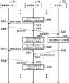
- steps S23 and S24 in FIG. 8 at the i-th iteration described in FIG. 7 are steps S41 to S45 and S48 in FIG. 10, and steps S23 and S24 in FIG. 8 at the i + 1-th iteration.
- step S41 the parent 1a randomly determines that the child 1b is to use A among the ranging signals A, B, and ⁇ C, and notifies the determination in step S42 to the child 1b. Receives the notification in step S43.
- the child 1b transmits the ranging signal A in step S44 according to the notification, and the parent 1b receives the ranging signal A in step S45.
- the distance measurement signal A is recorded in the unauthorized terminal 102 in step S46, and the distance measurement signal A is illegally extracted and acquired by analyzing the record in step S47.
- step S48 the parent 1a performs the i-th ranging process and tries the i-th fraud determination. Since the i-th time only receives the ranging signal A in an appropriate time zone, it is determined that there is no fraud.
- step S49 the parent 1a randomly determines that B should be used from A, B, and C as the i + 1th distance measurement signal, and notifies the child 1b in step S50.
- step S51 the child 1b receives the notification.
- the unauthorized terminal 102 that obtained the ranging signal A illegally transmits the ranging signal A illegally at step S52, and the parent 1a receives the illegally transmitted ranging signal A at step S53.
- the child 1b transmits the ranging signal B in step S54 according to the notification in step S51, and the parent 1b receives the ranging signal B in step S55.
- step S56 the parent 1a performs the i + 1th distance measurement processing based on the reception time of the distance measurement signal B received in step S55, and determines whether the i + 1th time of fraud has occurred. .
- the i + 1-th time is determined to be fraudulent because a distance measurement signal A different from the designated distance measurement signal B was received in step S53.
- fraud is determined by confirming reception of signals other than the type designated as the child 1b for the i-th time from m types of distance measurement signals set in advance.
- m types are determined randomly, so that even if the unauthorized terminal 102 can illegally acquire all of the m types, it is appropriate for what is actually used at the i-th time.
- the probability is 1 / m.
- the result of the i-th distance measurement process greatly changes from the result of the last i-1 distance measurement process (distance E (i-1)). If it is, it is determined that there is fraud.
- the case where the determination is made is a case where the unauthorized terminal 102 accidentally transmits the same type of m types of ranging signals as those to be used for the i-th time, but the original child 1b has transmitted. Since it is not a thing, fraud is determined using the possibility that an unnatural distance is likely to be obtained.
- This determination can be made by a predetermined threshold determination for the difference (absolute value) between the distance E (i) and the distance E (i-1). In addition to setting the threshold as a constant, the following can be set.
- the maximum moving speed assumed for the child 1b is prepared as v max
- the maximum distance traveled during the distance measurement processing interval T (i) described in FIG. 7 is v max * T (i )
- the maximum distance may be used as a threshold value.
- the moving speed v (which may be an average value) is calculated by an acceleration sensor or the like in the sensor unit 7b included in the child 1b, and v * T (i) + ⁇ may be used as a threshold value.
- ⁇ is a positive constant for setting the threshold value with a margin.
- fraud may be determined based on an abnormality in the transmission / reception time of the distance measurement signal.
- the third embodiment is based on the premise that the distance measurement signal is transmitted and received in both directions instead of in one direction.
- T ba t i [receive] -t i [send]
- the third embodiment also has an effect of eliminating the influence of fraud in [Case 2] described in FIG.
- step S24 the distance measurement processing and fraud determination in step S24 are completed, and when the process proceeds to step S25, the case determination is performed depending on whether or not the fraud determination is made in step S24, and the fraud determination is made. If so, the process proceeds to step S26. If not, the process proceeds to step S27.
- step S26 under the instruction of the fraud determination unit 51a, the function execution unit 6a performs processing for fraud handling, and then proceeds to step S27.
- the content of the handling process can be set by selecting a desired combination from the following (1) to (5).
- m kinds of combinations of ranging signals to be used in the child 1b are prepared in a plurality of sets, and if fraud is detected, the set to be used is switched from the next ranging process. May be.
- a set S 1 composed of m 1 type, and the set S 2 consisting of m 2 types, the set S 3 consisting of m 3 types leave the ready, each time the fraud detection is performed, S 1 ⁇ S 2 , S 2 ⁇ S 3 , S 3 ⁇ S 1, etc.
- the set S 2 is used, even if a distance measurement signal of a set S 1 different from this is detected, it may not be determined that it is illegal.
- step S27 cases are classified according to whether or not the result of the ranging process in step S24 is equal to or less than a predetermined threshold value that defines the function execution range R11 of FIG. 9, and if it is equal to or less than the threshold value, the process proceeds to step S28. move on. If it is not less than or equal to the threshold value, the process returns to step S22, and the process is continued for the next i-th (i + 1-th) described in FIG. In step S28, the value of the counter j is incremented by 1, and the process proceeds to step S29.
- step S29 it is determined whether or not the counter j has reached the predetermined value n. If it has reached, the process proceeds to step S30. If not, the process returns to step S23, and the next i-th time described in FIG. Continue processing for (i + 1).
- step S30 after the function execution unit 6a executes a predetermined function, the flow ends.
- a predetermined function for example, a door lock is released as a predetermined function.
- FIG. 11 is a diagram for explaining a first method in which transmission / reception of ranging signals is unidirectional
- FIG. 12 is a diagram for explaining a second method in which transmission / reception of ranging signals is bidirectional. It is. 11 and 12 respectively correspond to excerpts of portions related to steps (S8), (S9), etc., among the portions repeated as block B in FIG. A distance signal is being sent and received.
- the first method is based on the premise that time synchronization between the parent and child 1a, 1b is performed in advance as shown in step (T0) of FIG.
- a pulse-shaped ranging signal is transmitted from the child 1b side to the parent 1a side.
- the transmission time tb1 is acquired on the child 1b side.
- the reception time ta1 is acquired on the parent 1a side.
- the child 1b side notifies the acquired transmission time tb1 to the parent 1a side.
- step (T1-2) the difference between the reception time ta1 acquired by itself and the transmission time tb1 on the child 1b side is multiplied by the speed of a known distance measurement signal in advance.
- the distance between the parent and child 1a, 1b is calculated.
- the above is the process for one time as shown as block T10, and the same process is continued after the second time as shown as block T20.
- time synchronization is possible by using a GPS (Global Positioning System) signal or the like.
- the required accuracy of time synchronization depends on the required accuracy of distance calculation and the type of radio of the ranging signal. For example, when the required accuracy of distance calculation is 50 cm, the required accuracy of time synchronization of radio waves is 1.67 ns, and the required accuracy of time synchronization of sound waves / ultrasound is about 0.15 ms.
- the parent 1a may be used as a distance measurement signal transmission side and the child 1b may be used as a reception side.
- the second method shown in FIG. 12 is a method that does not require time synchronization.
- the second method uses a method similar to NTP (Network Time Protocol) widely used on the Internet.
- each of the parent and child 1a, 1b transmits a distance measurement signal, and each of them measures the transmission time of its own transmission signal and the reception time of the other party's transmission signal.
- the transmission time and reception time of the child 1b are Tm_s and Tm_r.
- the transmission time and reception time of the parent 1a are Tc_s and Tc_r.
- the clock error between the parent and child 1a, 1b is ⁇ t.
- the propagation time P_T is calculated by the following equation. Accordingly, the propagation time can be calculated without being affected by the time difference ⁇ t.
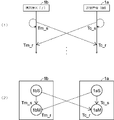
- FIG. 12 conceptually explains each time of the above formula.
- (1) shows the time from the viewpoint on the time axis
- (2) shows the time from the viewpoint on the transmission / reception device.
- the distance measurement signal transmitters (speakers for sound waves) of the parent 1a and child 1b are 1aS and 1bS, respectively
- the distance measurement signal receivers of the parent 1a and child 1b (for sound waves) And microphone) are 1aM and 1bM, respectively.
- Tm_s is the time when 1bM receives 1bS transmission
- Tm_r is the time when 1bM receives 1aS transmission.
- the child 1b that has received the transmission of the distance measurement signal from the parent 1a side immediately transmits the distance measurement signal toward the parent 1a side using the reception as a trigger.
- the interval T (i) described in FIG. 7 is managed only on the parent 1a side, and there is no need to notify the child 1b side. From the viewpoint of preventing [Case 2] fraud in FIG. 3, it is preferable to notify the interval T (i) to the child 1b side.
- the distance measurement signal setting unit 41a, the distance calculation unit 5a, the fraud determination unit 51a, and the function execution unit 6a are configured on the parent 1a side, but some or all of them are included. It may be provided on the child 1b side. In this case, necessary information may be exchanged between the parent and child 1a, 1b via the information transmitting / receiving units 40a, 40b.
- the ranging signal setting unit 41a is provided in both the parent 1a and the child 1b, and when the ranging signal is transmitted / received in both directions, each determines the constituent frequency of one of the ranging signals. You may make it do. In the case of transmission / reception in a single direction, the constituent frequency of the ranging signal may be determined by either one.
- the interval T (i) described with reference to FIG. 7 may be set for only one of them.
- the ranging signal is configured by a well-known technique so that the same information as the bit string can be transmitted, and a bit string is randomly generated for each transmission / reception. It may be.
- the determination of the interval T (i) described in FIG. 7 it may be a fixed value or may be determined randomly within a predetermined range.
- the first value is set when the value of the counter j in FIG. 8 is zero, and when the counter becomes 1 or more, a second value smaller than the first value is set. May be.
- the determination frequency can be increased so that the function execution determination can be made promptly.
- a predetermined function such as unlocking
- the distance measurement result is determined to be within the threshold value n times continuously and within the function execution range R11.
- the conditions may be relaxed. That is, in the past n determination results, a predetermined function may be executed when it is determined that the distance measurement result is equal to or greater than a certain ratio and equal to or less than the threshold and is within the function execution range R11.
- the predetermined function can be executed stably. Can do.
- radios can be used.
- a sound wave is used as a distance measurement signal, Otherwise, radio waves may be used.
- Wi-Fi registered trademark
- control signals signals other than ranging signals between the parent and child 1a and 1b
- High-precision distance measurement can be achieved by using sound waves having a low propagation speed for transmission and reception of distance measurement signals.
Landscapes
- Engineering & Computer Science (AREA)
- Radar, Positioning & Navigation (AREA)
- Remote Sensing (AREA)
- Physics & Mathematics (AREA)
- Computer Networks & Wireless Communication (AREA)
- General Physics & Mathematics (AREA)
- Acoustics & Sound (AREA)
- Mechanical Engineering (AREA)
- Lock And Its Accessories (AREA)
- Radar Systems Or Details Thereof (AREA)
- Measurement Of Velocity Or Position Using Acoustic Or Ultrasonic Waves (AREA)
- Selective Calling Equipment (AREA)
Abstract
測距信号の送受で算出される距離に基づいて所定機能を実行する距離測定システムを、不正取得された測距信号がある状況においても安全に機能させる。 測距信号送受部4a,4b間では、測距信号を送受し、その送受時刻を求める。距離算出部5aは、送受時刻より距離を算出する。測距信号は、毎回の送受ごとに、複数種類の中からランダムに選択され、選択された測距信号に基づいて距離を算出する。機能実行部6aは、選択された測距信号において閾値以内の距離が算出されることが所定期間継続した場合に初めて、所定機能を実行する。不正送信された測距信号が、連続して選択されたものと一致する確率は低いため、安全に所定機能が実行される。
Description
本発明は、スマートキーシステム等に好適な、携帯端末と送受信機との間の距離に基づいて所定機能を実行する距離測定システムに関し、特に、当該距離の算出において利用する測距信号が、不正に取得され送信される場合があっても、安全に所定機能を実行することのできる距離測定システムに関する。
自動車を中心にスマートキーシステムが普及している。スマートキーシステムを利用することで、ユーザは鍵を車両ドアの鍵穴に差し込むことなく解錠・施錠できる。一般的なスマートキーシステムでは、ユーザの持つ携帯機と車載の送受信機で通信を行い、認証する。そして、認証が正常に済んだ場合にドアロックを解錠する。この際、125kHzや300Mhzの専用の無線機を用いることで、送受信機の無線信号の範囲は2m程度の短距離に制限されている。これにより、ユーザが車両から離れている場合にドアが解錠され第三者が車内に侵入できてしまうなどのセキュリティ問題を解決している。
しかしながら、このようなスマートキーシステムでは、不正に無線信号を送受信することで解錠する盗難の手法が知られている。この問題を防ぐ技術は多く提案されている。例えば、特許文献1では、正規の所有者が有する携帯機と車両との間でクロックの誤差を補正するような仕組みを持たせることにより、不正なドアロックの解錠による被害を効果的に抑制している。
ところで、本出願人による特願2013-130612号(以下、特許文献2とする)の距離測定システムでは、スマートキーシステムの携帯機としてスマートフォン等の携帯端末を利用することが可能である。これによりユーザの利便性を向上できる。スマートフォンにはbluetooth(登録商標)やWi-Fi(登録商標)等の無線機が具備されている。しかし、これらを用いた場合、従来のスマートキーシステムにおける専用の無線機のように通信範囲を制限することはできない。そのため、特許文献2では、以下の手順によりスマートキーシステムを実現している。
図1は、特許文献2における手順を模式的に説明するための図である。図1では、自動車C1に設置された送受信機100と、当該自動車C1のユーザU1が有する携帯機101と、からなる距離測定システムが示されると共に、模式的に手順(1)~(3)が示されている。
まず、手順(1)として示すように、ユーザU1と共に移動した携帯機101が無線通信可能範囲R10内に入った際に、双方向矢印A1で示すように、送受信機100と携帯機101との間であらかじめ設定した鍵を交換することで認証が行われる。
手順(1)の認証完了後、手順(2)として示すように、送受信機100と携帯機101との間で双方向矢印A2に示すような音波の送受による測距が開始され、送受信機100は当該音波の送受時刻に基づいてユーザU1と車両C1の距離(携帯機101と送受信機100の距離)を継続的に推定する。ユーザU1は携帯機101と共に軌跡P1で範囲R10内を移動し、この間、継続して当該手順(2)による測距が行われる。(なお、当該移動している際のユーザU1は、図1中では描くのを省略している。)
さらに、手順(3)として示すように、ユーザU1が車両C1に近づき、測距結果が閾値以下になる範囲R11内に到達した場合に、送受信機100は自動車C1のドアロックを解錠する。これらの手順により、専用機を用いた場合と同様に、スマートフォン等の汎用的な携帯機101を用いて、一定範囲R11内のみにおける解錠を実現することができる。
以上のように、特許文献2では、電波での通信による認証と音波による測距技術とを用いることで、スマートキーシステムを実現している。しかしながら、測距に用いる音波はレコーダ等により簡単に録音・再生が可能であるため、以下のような手順によって不正にドアロックを解錠されてしまうという問題があった。
図2は、当該不正な手順を模式的に説明するための図である。図2にて、自動車C1に設置された送受信機100とユーザU1の携帯機101とは、図1の構成と同様であり、また、手順(1)及び(2)までについては、図2においても図1と同様に実施されている。図2では、当該構成において、図1のように正規のユーザU1によって手順(3)が実施される代わりに、悪意ある第三者等の不正ユーザU2が不正端末102を用いて、不正な手順(4), (5), (6)を実施する。
すなわち、図2では、まず、手順(1)にて正規のユーザU1が携帯機101と共に認証範囲R10に入って認証が実施され、手順(2)のように、音波による測距が開始され継続される。当該手順(2)において、正規のユーザU1が速やかに車両C1に到達すれば、図1の場合のように無事に手順(3)が実施されるが、図2では、ユーザU1が移動の軌跡P1の途中において、例えば立ち止まって話を始めたなどで、ただちに手順(3)へとは至らなかった場合を想定している。
こうして、手順(2)が継続されている間に、不正ユーザU2が不正端末102を操作して不正な手順(4), (5), (6)を実施する。手順(4)にて、不正端末102は、手順(2)で双方向矢印A2として送受信機100と正規の携帯機101と間で送受されている音波を、いわば盗聴する形で、不正に録音する。すなわち、矢印A3に示すように、正規の携帯機101の送信する音波を不正録音し、また、矢印A4に示すように、送受信機100の送信する音波を不正録音する。
さらに、手順(4)では、不正録音内において、周期的に受信される音波を特定するなどの手法で、及び/又は、不正ユーザU2自身の判断を適宜加えた音波解析手法で、不正端末102は、正規の携帯機101の送信する音波と、送受信機100の送信する音波とを不正に特定する。
手順(5)にて、不正ユーザU2が不正端末102を持って軌跡P2のように移動しながら、不正端末102は不正録音した携帯機101の送信音波を送信する。(なお、ユーザU1と同様に、図中では不正ユーザU2も、移動中のものは描くのを省略している。)こうして手順(5)では、送受信機100においては、自分自身では双方向矢印A2に示す正規の携帯機101との間の音波の送受時刻で測距を実施しているつもりであるにも関わらず、実際には双方向矢印A5に示すように、不正端末102との間における音波の送受時刻に基づいた、不正端末102と送受信機100との間の測距を実施してしまうこととなる。
すなわち、不正端末102は、不正録音した音波を用いることで、送受信機100に対して、測距処理に関して正規の携帯機101になりすますことが可能となってしまう。この際、不正録音した携帯機101の音波を不正端末102は不正送信する。
こうして、手順(5)によって不正端末102が正規の携帯機101になりすましながら軌跡P2のように移動し、結果として手順(6)に示すようにロック解除の範囲R11内に到達してしまった際に、正規のユーザU1の携帯機101は未だ遠方に存在するにも関わらず、送受信機100は接近してきた不正ユーザU2の不正端末102に対して、車両C1の不正なロック解除を実行してしまうこととなる場合がある。
また、より一般には、図2のような不正端末102によるなりすましの他にも、次のような問題がある。すなわち、不正録音した音波を意図的なタイミングあるいはランダムなタイミングで送信することによって、不正端末102が範囲R11内に必ずしも到達していなくとも、不正な送受時刻を用いることになってしまう送受信機100等に、不測の誤動作を発生させてしまう問題である。
さらに、同様に次のような問題もある。すなわち、図2では、送受信機100における送受時刻(のうち受信時刻)が不正なものになってしまう例を説明したが、音波の送受が送受信機100と正規の携帯機101との双方向でなされる状況においては、同様に、携帯機101における送受時刻(のうち受信時刻)が不正なものになってしまうという問題である。この場合も同様に、不測の誤動作が発生しうる。図13は、当該問題を説明するための図である。
図13では、(1)に不正な音波の送受がない場合を、(2)に当該問題となる場合を、それぞれ示している。(1)では、送受信機100と携帯機101との間で正しく音波の送受がなされる。すなわち、[1]に示すように送受信機100が携帯機101へと向けて正規の音波Aを送信すると、[2]に示すように携帯機101が当該音波Aの受信時刻を無線等で送受信機100へと通知する。また、[3]に示すように、携帯機101は送受信機100へと向けて正規の音波Bを送信する。
こうして、(1)の場合においては、双方向に送信された正規の音波A,Bの受信時刻を送信機100が取得して、携帯機101との距離を正しく算出する。そして、図2で説明した不正は、当該音波Bが不正端末102によって不正送信されてしまうものであった。しかしながら同様に、音波Aも不正録音可能であるため、音波Aも不正送信されうる問題があり、図13の(2)は両音波A,Bが不正送信される状況を示している。
すなわち、図13の(1)における[1],[2],[3]に代えて、(2)ではそれぞれ不正な手順[11],[12],[13]が実施されてしまう。[11]では、不正端末102が不正に音波Aを携帯機101に送信する。[12]では、携帯機101が当該不正に受信した(不正と知らずに受信した)音波Aの受信時刻、すなわち不正な受信時刻を送受信機100へと無線等で通知する。さらに、図2の場合と同様に、[13]では不正端末102が不正に音波Bを送受信機100へと送信する。
こうして、(2)の場合においては、双方向に送信される音波A,Bの両者が不正送信され、両者の不正な受信時刻を送信機100が取得して距離を算出してしまう。従って、当該距離は不正なものとなる。さらに同様に、音波Aのみが不正送信される状況も考えられ、この場合も不正な距離が算出されてしまう。
以上のような問題は、特許文献2のようなスマートフォン等の汎用端末と音波による測距技術を用いた、新しいスマートキーシステム特有の課題である。そのため、特許文献1のような、多く提案されている従来のスマートキーのセキュリティ問題を解決する技術では、解決することができない。
本発明は、上記課題に鑑み、不正な信号の送信があっても安全に機能することのできる距離測定システムを提供することを目的とする。
上記目的を達成するため、本発明は、携帯端末及び送受信機を備え、当該両者の間の距離を測定し、当該距離に基づいて所定機能を実行する距離測定システムであって、当該両者が、測距信号を継続的に送受すると共に、その送受時刻を求める測距信号送受部を含み、前記携帯端末又は送受信機は、前記測距信号の送受時刻に基づいて、当該両者の間の距離を算出する距離算出部を含み、前記携帯端末又は送受信機は、前記算出された距離に基づいて、所定機能を実行する機能実行部を含み、前記携帯端末及び送受信機の間では、前記送受する測距信号について、送受の各回において複数種類の信号から選択したものを利用し、前記機能実行部は、前記選択された測距信号を受信すること及び前記算出された距離が所定閾値以下であることが、所定条件を満たして継続したと判定される場合に、前記所定機能を実行することを特徴とする。
本発明によれば、測距信号は送受の各回において複数の中から選択され、当該選択された測距信号が継続受信されなければ所定機能を実行しない。従って、測距信号が不正取得され不正送信されても、各回において選択されたものと連続して一致する可能性が低いことから、安全に所定機能が実行される。
図3は、本発明の距離測定システム100の構成概要を説明するための図である。距離測定システム100は、送受信機1a及び携帯端末1bを備える。図3では、一例として送受信機1aが自動車C1に設置されているところが概念的に描かれている。当該自動車に設置する場合、距離測定システム100をスマートキーシステムに利用することができる。送受信機1aはまた、自動車以外にも、自転車、オフィスや自宅のドア、パーソナルコンピュータ(PC)その他に設置されてもよい。携帯端末1bには、スマートフォンや携帯電話を利用することができる。
なお、本発明の説明においては、特に、送受信機1aと携帯端末1bとの間でのやりとりを説明する場合には適宜、送受信機1aを親機であるものとして親1aと略称し、携帯端末1bを子機であるものとして子1bと略称する。
本発明においては、特にスマートキーシステムに適用される場合には、親1aが定位置に固定され、子1bはユーザが携帯して移動する状況を想定しているが、用途によっては逆であっても、あるいは両者が移動してもよい。親子1a,1b間では、無線のやりとりがなされることにより、図3に示すようにその間の距離Eが時系列上で逐次、算出される。親1aは当該算出された距離Eに基づいて所定の機能を実行する。
当該距離Eの算出に際して、親子1a,1b間で測距信号が送受される。本発明によれば、当該測距信号を不正に録音・取得して送信する不正端末102の影響を排除しつつ、親子1a,1b間で送受される測距信号を識別したうえで適切に距離Eを算出し、距離Eに基づく所定機能の実行を安全に行うことが可能となる。なお、当該影響排除を行う旨の理解補助のため、図3では不正端末102が描かれているが、距離測定システム100に不正端末102が含まれるわけではない。(後述の図4、図10等でも同様である。)
なお、以下、不正端末102の行う不正は、図3にて[ケース1]として示す不正、すなわち、送受信機1aにおいて受信される測距信号を不正に送信すること(図2で説明した不正)であるとして、主として本発明による当該[ケース1]への対策の説明を行う。図3にて[ケース2]として示す不正、すなわち、不正端末102が、携帯端末1bにおいて受信される測距信号を不正に送信すること(図13で説明した不正)への本発明による対策も可能であるが、これについては付随的に説明する。(具体的には後述する図8のステップS23の説明等において[ケース2]の対策を説明する。)
図4は、距離測定システム100を構成している送受信機1a及び携帯端末1bの機能ブロック図である。送受信機1aは、範囲判断部2a、認証部3a、鍵管理部30a、情報送受部40a、測距信号送受部4a、測距信号設定部41a、距離算出部5a、不正判定部51a及び機能実行部6aを備える。携帯端末1bは、範囲判断部2b、認証部3b、鍵管理部30b、情報送受部40b、測距信号送受部4b及びセンサ部7bを備える。
なお、親子1a,1b間にて、同一名を付与し且つ対応する符号を付している機能ブロック同士(例えば、親1aの範囲判断部2aと、子1bの範囲判断部2b)は、同一の又は対応する機能を担う。以下、各部の概要を説明する。
範囲判断部2a,2bでは、親1a側(範囲判断部2a)より、子1b側(範囲判断部2b)へと定期的にビーコン信号を送信する。子1b側では、当該ビーコン信号を受信した場合には、親1a側へと応答する。
なお、以下にてさらに各機能部を説明するに際して、親子1a,1b間で同一の又は対応する処理がなされる場合には、上記の範囲判断部2a,2bの説明と同様に、「親1a側」及び「子1b側」などにより、「親1a側の機能部Xa」及び「子1b側の機能部Xb」を表すものとする。ここで、Xに該当するのは2, 3, 30, 4, 40である。
認証部3a,3bでは、上記ビーコン信号の送信及び応答により親子1a,1b間が無線通信可能であることが確認された際に、続いて、無線により親子1a,1b間での認証を行う。当該認証を可能とすべく、親子1a,1bではそれぞれ、鍵管理部30a,30bにより、予め自身の鍵情報を設定し管理しておく。
情報送受部40a,40bでは、本発明における距離算出処理、不正判定処理、所定機能実行処理その他を実施するのに必要となる情報を、親子1a,1b間にて無線により互いに送受する。特に、親1a側から子1b側へは、子1bに送信する測距信号の情報(構成周波数や送信タイミングなど)を通知し、子1b側から親1a側へは、子1bにおける測距信号の送受時刻を通知するが、実施形態に応じてその他の情報も送受される。
測距信号送受部4a,4bでは、上記認証の完了後に、親子1a,1b間にて単方向又は双方向で測距信号の送受を継続的に行うと共に、当該測距信号の送受時刻を記録する。測距信号設定部41aは、当該送受する測距信号の設定(構成周波数や送信タイミングなど)を行う。当該設定は、情報送受部40a,40bを介して子1b側にも共有される。
なお、測距信号の設定が上記のように共有されていることから、測距信号送受部4a,4bでは、信号を継続的に記録(測距信号が音波であれば録音)し、当該記録の中から、送信タイミングから定まる所定精度での受信時刻範囲内において、構成周波数などによって測距信号を識別して、送受時刻を求めることができる。測距信号の送受は単方向又は双方向が可能であるが、以下では基本的には、双方向の場合を前提として説明する。
また、本発明では特に、各回の測距信号を所定のm種類の中からランダムに決定することで、不正な測距信号が当該m種類の中の実際に使用されたものと一致してしまうことの確率を下げる。
距離算出部5aは、測距信号送受部4a,4b間でなされた測距信号の送受時刻に基づいて、親子1a,1b間の距離を算出する。ここで、測距信号が継続して送受され、送受時刻も継続して取得されるので、当該距離も、時系列上で継続的に算出される。なお、当該距離算出の処理は適宜、測距処理とも称する。
不正判定部51aは、距離算出部5aの測距処理と連動して、測距信号送受部4aでの送受信号の記録(測距信号が音波であれば、録音)を解析して、当該測距処理のなされた時点の近くにおいて、親1aへと向けた不正端末102による不正測距信号の送信があったか否かを判定する。当該不正があった旨の判定が下された場合には、不正判定部51aは、機能実行部6a及び/又は測距信号設定部41aに、種々の指示を与える。
機能実行部6aは、距離算出部5aの算出した距離に基づいて、所定機能を実行する。親1aが自動車に設置されていれば、当該距離が閾値以下となった場合に、自動車のドアのロックを解除し、閾値より大きくなった場合に、自動車のドアをロックしてもよい。さらに別の閾値を併用して同様に、エンジンロックの解除/設定を行ってもよい。
機能実行部6aでは上記と同様の閾値判定により、親1aが自転車、オフィスや自宅のドア、パーソナルコンピュータ(PC)その他に設置されている場合も、対応する鍵の解除/施錠を行うことができる。例えばPCの場合であれば、画面ロックの制御を行ってもよい。また、その他の用途の所定機能が実行されてもよい。
なお、詳しくは後述するように、機能実行部6aでは、距離算出部5aの算出した距離が閾値条件を満たした時点でただちに所定機能を実行するのではなく、当該距離の閾値条件を満たすことが継続することを、所定機能を実行するための条件として課す。本発明では、当該条件を課すことで、m種類の測距信号のうち実際に使用されたものと不正な測距信号とが一致し続ける確率が指数関数的に小さくなるので、不正端末102による不正な測距信号の影響を排除することができる。
機能実行部6aはまた、上記のような距離算出部5aの算出した距離に基づいた機能実行の他にも、不正判定部51aより不正判定を下した後の指示を受けて、例えばアラームを鳴らすなどの種々の機能を実行する。
以上、図4の各部の概要を説明したので、補足事項を説明する。上記各機能部により親子1a,1b間にて信号や情報のやりとりがなされる場合、各種の無線を利用することができる。無線の種類として、音波や超音波、また、Wi-Fi(登録商標)、Bluetooth(登録商標)などの電波などが利用でき、各機能部ではそれぞれ個別の種類の無線を利用してよく、この際、同一種類の無線が利用される機能部があってもよい。また、各機能部では、扱う情報の種類に応じて、別種類の無線を利用してもよい。
なお、範囲判断部2a,2bにおけるビーコン信号及びその応答と、測距信号送受部4a,4bにおける測距信号の送受に関しては、親子1a,1b間での当該無線信号が直接到達する種類のものである必要がある。その他のやりとりは、親子1a,1b間で無線信号が必ずしも直接に到達する必要はなく、3GやLTE等による基地局経由で、別途の有線/無線ネットワーク上のサーバなどを介するものであってもよい。ただし、測距信号の設定情報等、所定時間内に到達する必要があるものには、直接到達する種類の信号を用いることが好ましい。
以下、本発明による処理手順を説明する。
本発明における測距処理には、測距信号が親子1a,1b間にて直接到達することが必要である。従って、当該直接到達が可能かをまず識別するために、本発明の処理手順は、親子1a,1bが無線通信可能範囲外にあるか、無線通信可能範囲内にあるか、によって場合分けされて実施される。図5は、当該無線通信可能範囲内外による処理手順の場合分けを説明するための図である。
図5では、固定位置にある親1aを中心として無線通信可能範囲R10が示されており、子1bが当該範囲R10内に存在する場合に、親子1a,1b間では無線が直接到達することによる通信や測距が可能である。図5では、(2)が範囲R10内に子1bが存在する場合を、(1)及び(3)が範囲R10外に子1bが存在する場合を、それぞれ例として示している。当該区別のもと、各範囲では以下のような手順が実施される。
(1.無線通信可能範囲外の場合)
無線通信可能範囲外の場合、親子1a,1b間では範囲判断部2a,2bによるビーコンの送受のみが試みられる。こうして、親1aは無線通信可能範囲内に子1bが入ってくるのを待機し、子1bは当該範囲内に入ったかを常時監視する。具体的には、親1aの範囲判断部2aは所定周期にてビーコン信号を送信し、子1bからの応答を待機する。一方、子1bの範囲判断部2bは、ビーコン信号の受信があるかを監視し続け、受信があった場合には応答を行う。
無線通信可能範囲外の場合、親子1a,1b間では範囲判断部2a,2bによるビーコンの送受のみが試みられる。こうして、親1aは無線通信可能範囲内に子1bが入ってくるのを待機し、子1bは当該範囲内に入ったかを常時監視する。具体的には、親1aの範囲判断部2aは所定周期にてビーコン信号を送信し、子1bからの応答を待機する。一方、子1bの範囲判断部2bは、ビーコン信号の受信があるかを監視し続け、受信があった場合には応答を行う。
(2.無線通信可能範囲内の場合)
図6に、上記無線通信範囲外にあった後、無線通信可能範囲内に入ってきた以降の親子1a,1b間での処理手順を示す。ここで、ステップ(S1)~(S4)については、図5の矢印A12のように無線通信可能範囲内に入ってきたことが検出され、認証が実施される手順である。一方、ステップ(S5)にて開始通知した後のステップ(S6)~(S11)が、ブロックBとして囲まれるように繰り返し実施される、無線通信可能範囲内の手順に相当する。
図6に、上記無線通信範囲外にあった後、無線通信可能範囲内に入ってきた以降の親子1a,1b間での処理手順を示す。ここで、ステップ(S1)~(S4)については、図5の矢印A12のように無線通信可能範囲内に入ってきたことが検出され、認証が実施される手順である。一方、ステップ(S5)にて開始通知した後のステップ(S6)~(S11)が、ブロックBとして囲まれるように繰り返し実施される、無線通信可能範囲内の手順に相当する。
(2-1.無線通信可能範囲内に入ったことの検出及び認証)
ステップ(S1)では、子1bが範囲R10内に移動してきたことにより、親1aの送信したビーコン信号が子1bで受信される。ステップ(S2)では、子1bは当該ビーコン信号に対して、親1aへと応答信号を送る。こうして、子1bはビーコン信号の受信で範囲R10内に存在することを知り、無線通信可能範囲内の処理へ切り替え可能となる。同じく、親1aも、応答信号の受信により、範囲R10内に子1bが存在することを知り、無線通信可能範囲内の処理への切り替えが可能となる。
ステップ(S1)では、子1bが範囲R10内に移動してきたことにより、親1aの送信したビーコン信号が子1bで受信される。ステップ(S2)では、子1bは当該ビーコン信号に対して、親1aへと応答信号を送る。こうして、子1bはビーコン信号の受信で範囲R10内に存在することを知り、無線通信可能範囲内の処理へ切り替え可能となる。同じく、親1aも、応答信号の受信により、範囲R10内に子1bが存在することを知り、無線通信可能範囲内の処理への切り替えが可能となる。
ステップ(S3)では、前述のように認証部3a,3bにより親子1a,1b間にて認証処理すべく、子1b側より親1a側へと鍵情報を送信し、ステップ(S4)では、当該子1bより受信した鍵情報と親1a自身が保持している鍵情報とを比較して、親1a側が子1bの認証を行う。鍵情報については前述のように鍵管理部30a,30bに予め設定しておく。なお、鍵情報の親子1a,1b間での送受信の態様に関して、例えば子1b側で認証を行う、相互に行うなど、ステップ(S3),(S4)以外の手法で認証が実施されてもよい。
当該ステップ(S4)の認証が成功した場合は、ステップ(S5)により親1aから子1bへと測距処理の開始通知を行った後、ステップ(S6)以降の無線通信可能範囲内での処理へと進む。なお、当該ステップ(S4)の認証が失敗した場合には、ステップ(S5)以降での処理へは進まず、上記(1.無線通信可能範囲外の場合)での処理に戻る。
なお、ステップ(S5)の開始通知の際に、親子1a,1b間で時計合わせを行うようにしてもよい。当該時計合わせは、測距処理(詳細は後述)において必要な精度でなされればよい。
(2-2.無線通信可能範囲内の処理手順)
ステップ(S6)では、測距信号設定部41aが、測距信号送受部4a,4bで送受する測距信号の設定を行う。ステップ(S7)では当該設定を親1aから子1bへと通知することで、当該設定を親子1a,1b間で共有する。ステップ(S8)では、当該共有された設定に従って、測距信号送受部4a,4bが測距信号を送受し、送受の時刻を記録する。ステップ(S8)ではさらに、子1bが当該記録した送受時刻を親1aへと通知する。
ステップ(S6)では、測距信号設定部41aが、測距信号送受部4a,4bで送受する測距信号の設定を行う。ステップ(S7)では当該設定を親1aから子1bへと通知することで、当該設定を親子1a,1b間で共有する。ステップ(S8)では、当該共有された設定に従って、測距信号送受部4a,4bが測距信号を送受し、送受の時刻を記録する。ステップ(S8)ではさらに、子1bが当該記録した送受時刻を親1aへと通知する。
ステップ(S9)では、距離算出部5aが、測距信号送受部4a,4bで取得した親1a側及び子1b側の双方の送受時刻に基づいて、当該時点における親子1a,1b間の距離を算出する。ステップ(S10)では、不正判定部51aが、当該距離算出の際に、不正の測距信号の受信があったか否かを判定する。
ステップ(S11)では、当該算出された距離が一定の期間に渡って所定条件を満たした場合に、機能実行部6aが所定機能(スマートキーシステムであれば、ロック解除など)を実行する。ステップ(S11)ではまた、直前のステップ(S10)にて不正判定が下された場合には、機能実行部6aが不正に対処するための所定機能を実行する。
以上、ステップ(S6)~(S11)は、ブロックBとして囲まれるように、繰り返し実行される。この際、ステップ(S8)での測距信号の送受処理の各回i(i=1, 2, 3, ...)の間隔T(i)に従って、当該ブロックBも間隔T(i)を置いて繰り返し実行される。図7は、当該測距信号の送受その他の繰り返しを模式的に示す図であり、ここでは、測距信号が親子1a,1b間の双方向で送受される場合の例を示している。(後述のように、測距信号は親子1a,1b間の単方向で送受するようにしてもよい。)
図7に示すように、間隔T(i)は、親1aがi回目に送信する時刻Ti[送信]とi+1回目に送信する時刻Ti+1[送信]との間隔として、与えることができる。繰り返しi回目におけるステップ(S8)の測距信号の送受処理は、双方向の送受の場合、図示するように、当該親1aによる時刻Ti[送信]における測距信号の送信と、当該送信に対する子1bによる時刻Ti[受信]における受信と、子1bによる時刻ti[送信]における測距信号の送信と、当該送信に対する親1aによる時刻ti[受信]における受信と、からなる。なお、単方向の送受の場合は、当該図示しているうちの片方のみの処理がなされる。
そして、図示するように、親1aにおけるi回目の受信時刻ti[受信]と、i+1回目の送信時刻Ti+1[送信]と、の間の期間において、ブロックBの繰り返しi回目におけるステップ(S9),(S10),(S11)が時点P1にて実行され、また、ブロックBの繰り返しi+1回目におけるステップ(S6),(S7)が時点P2にて実行される。時点P1, P2は同時でもよい。
従って、当該間隔T(i)は、測距信号送受部4a,4bによる測距信号の送受信の間隔であり、距離算出部5aによる測距処理及び不正判定部51aによる不正判定処理の間隔であり、また、機能実行部6aが機能実行するか否かの判定の間隔でもある。なお、当該間隔T(i)は、ステップ(S7)にて子1b側へと通知されることにより、親子1a,1b間でタイミングを揃えて連携した処理が可能となる。
(3.無線通信可能範囲内から無線通信可能範囲外へ移動した場合の判断)
無線通信可能範囲内においては、以上の図6のブロックBの処理が繰り返されるが、当該繰り返しているうちに、子端末1bの移動により図5の矢印A23に示すように、無線通信可能範囲外に移動する場合もある。この場合、次のようにすればよい。
無線通信可能範囲内においては、以上の図6のブロックBの処理が繰り返されるが、当該繰り返しているうちに、子端末1bの移動により図5の矢印A23に示すように、無線通信可能範囲外に移動する場合もある。この場合、次のようにすればよい。
すなわち、図6のステップ(S8)において、親1a側及び子1b側のそれぞれにおいて、相手側から送信されるはずの測距信号が受信されないことが所定回数又は所定期間以上続いた場合に、当該親子1a,1bの両者は、無線通信可能範囲外になったものと判断し、上記(1.無線通信可能範囲外の場合)の処理に移行すればよい。なお、当該判断は、親1a側及び子1b側においてそれぞれ独立に行ってよい。
図8は、無線通信可能範囲内における、親1aの処理の詳細なフローチャートである。図8を参照して、図6にてブロックBとして示した繰り返し処理を詳細に説明する。
ステップS21は、図6のステップ(S4),(S5)に相当する。すなわち、ステップS21では認証を行い、認証に成功した場合にさらに測距開始通知を行ってから、ステップS22へと進む。なお、認証が成功しない場合は、成功するまではステップS22へは進まない。
ステップS22では、カウンタjを初期値0に設定して、ステップS23へと進む。当該カウンタjは、図7で説明した間隔T(i)で繰り返される測距処理による距離が、連続して所定閾値以下となる回数を数えるためのものである。図9に示すように、当該所定閾値によって、親1aを中心とした無線通信可能範囲R10内における機能実行範囲R11が定義される。
なお、本発明では特に、当該カウンタj及び図8の後述する各ステップにより、子1bが所定回数(n回)連続して機能実行範囲R11内に存在すると判定された場合に初めて、機能実行部6aが車のロック解除等の所定機能を実行することで、不正な測距信号によって所定機能が実行されることを排除する。ここで、不正端末102の不正な測距信号によって、n回連続で範囲R11内に存在すると判定されることは、確率的に極めて小さいことから、排除が可能となる。当該確率は、(1/m)nである。mについてはステップS23で説明する。
これに対して、特許文献2では、機能実行範囲R11内に存在すると1回だけ判定された時点で直ちに所定機能が実行されるため、不正な測距信号を偶然1回だけ所定タイミングで受信すると、不正にロック解除等が実施されてしまう。
ステップS23は、図6のステップ(S6),(S7)に相当し、測距信号設定部41aが測距信号を決定すると共に、子1b側へと当該決定した測距信号の情報を通知した後、ステップS24へ進む。具体的には、子1b側より親1a側へと送信する測距信号について、所定数m種類のものを定めておき、当該m種類の中からランダムに当該i回目(図7で説明した繰り返しにおけるi回目)に利用する測距信号を決定して、通知する。
測距信号は所定時間継続するパルス状のものとして構成する。測距信号に音波を用いる場合であれば、その周波数(18kHz, 19kHzなど)、周波数変化(低周波から高周波への変化、あるいはその逆の変化など)、信号長(前記所定時間継続する長さ)等の組み合わせにより互いを識別可能として、所定のm種類を用意しておけばよい。測距信号に電波を用いる場合も同様である。
なお、親1a自身が子1bへと送信する測距信号は、上記子1bが送信するm種類の中からランダムに選択したのと同様のものとしてもよいし、当該m種類とは独立に、常に同種類のものを利用するようにしてもよい。あるいは、親1aが子1bに送信する測距信号も、子1bの送信するのと同様に、M種類のものからランダムに決定するようにしてもよい。当該M種類は、子1b用に設定したm種類とは独立に設定してよい。なお、親1bの送信する測距信号もM種類用意すれば、不正端末102では測距信号の不正解析がより困難となる点で好ましい。
ステップS23では、上記親1a自身が子1bへと送信する測距信号の情報も子1b側へと通知することで、子1b側において当該測距信号を識別して受信時刻の算出を可能とさせる。ステップS23ではまた、図7で説明した間隔T(i)の情報も、子1b側へと通知し、子1b側において測距信号の送受が予想される所定時刻範囲内において、測距信号の識別を可能とさせる。
ここで特に上記のように、親1a自身が子1bへと送信する測距信号の情報を、上記のm種類またはM種類からランダムに選択したうえで、子1b側へ予め通知しておくようにすれば、図3で説明した[ケース2]の不正が成功してしまう確率を下げることができる。当該確率が下がる理由は、子1b側においては、当該m種類又はM種類の中から選択された1種類の測距信号を識別してその受信時刻を求めればよく、不正信号が当該ランダムに選択された種類以外で構成されていれば、子1bにおける識別対象から除外され、受信時刻が狂わされることはなく、不正は失敗するからである。また、間隔T(i)の情報も子1b側において利用すれば、[ケース2]の不正が成功する確率はさらに下がる。
ステップS24は、図6のステップ(S9),(S10)に相当し、測距信号送受部4a,4bの測距信号の送受時間に基づいて距離算出部5aが親子1a,1b間の距離を算出する測距処理を行うと共に、不正判定部51aが、不正送信された測距信号の有無を判定する。
ここで、距離算出部5aの測距処理については、子1b側にステップS23でランダムに決定して通知した測距信号を子1bが送信していることを前提に、当該子1bにより送信された測距信号を親1a側で想定される時間帯に受信することで、正しい測距処理が行われることを前提としている。当該測距処理が実は不正な測距信号に基づくものであった場合もありうるが、そのような場合の影響は、不正判定部51a及び図8のフローにおけるカウンタjの利用(前述のn回連続で不正が成立する確率(1/m)nの実現困難性)によって、排除される。
なお、測距処理そのものについては、周知の技術を利用することができ、その詳細は後述することとし、ここでは不正検出に関連する部分を説明する。
不正判定部51aは、種々の実施形態により、不正の測距信号の存在を判定する。以下、第一実施形態~第三実施形態としてこれらを説明する。当該第一実施形態~第三実施形態は、3つのうちいずれかのみを用いてもよいし、3つ全てまたは2つを実施して、少なくとも1つにおいて不正判定が下されることを確認してもよい。
第一実施形態では、当該i回目(図7で説明した繰り返しにおけるi回目)に本来は受信するはずのない種類の測距信号の受信を確認した場合に、不正測距信号が存在すると判定する。すなわち、当該i回目にはステップS23において、m種類の測距信号のうち第一種類のものを子1bに送信させるよう設定したにもかかわらず、m種類のうち、第一種類とは異なる第二種類の測距信号の受信が確認された場合に、不正判定を下す。当該受信を確認する範囲は、図7で説明した間隔T(i)の範囲でよい。
図10は、m=3種類の測距信号{A, B, C}を用いる場合に、当該第一実施形態で不正判定を下す具体例の手順(ステップS41~S56)である。なお、図7で説明した繰り返しのi回目における図8のステップS23,S24の例が、図10のステップS41~S45, S48であり、繰り返しのi+1回目における図8のステップS23,S24の例が、図10のステップS49~S51, S53~S56である。
ステップS41にて、親1aは、子1bに測距信号A, B, Cのうち、当該i回目にはAを使用させる旨をランダムに決定し、ステップS42で当該決定を通知し、子1bはステップS43にて当該通知を受け取る。子1bは当該通知に従い、ステップS44にて測距信号Aを送信し、親1bは当該測距信号AをステップS45にて受信する。
しかしここで、当該測距信号Aは、ステップS46にて不正端末102に記録され、ステップS47にて記録を解析して、測距信号Aを不正に抽出し、取得されてしまう。
親1aはステップS48にて、当該i回目の測距処理を行うと共に、i回目の不正判定を試みる。i回目は測距信号Aを適切な時間帯に受信しているのみであるので、不正はない旨の判定が下される。
ステップS49にて、親1aは、i+1回目の測距信号として、A,B,Cの中からBを使用すべき旨をランダムに決定し、ステップS50にて子1bに通知し、ステップS51で子1bは当該通知を受信する。
一方、測距信号Aを不正取得した不正端末102は、ステップS52にて当該測距信号Aを不正に送信し、親1aはステップS53にて当該不正送信された測距信号Aを受信する。
また、子1bはステップS51の通知に従い、ステップS54にて測距信号Bを送信し、親1bはステップS55にて当該測距信号Bを受信する。
親1aはステップS56にて、当該i+1回目の測距処理をステップS55にて受信した測距信号Bの受信時刻に基づいて実施すると共に、当該i+1回目に不正があったかを判定する。当該i+1回目については、ステップS53において、指定した測距信号Bとは異なる測距信号Aの受信があったことから、不正があったものとして判定する。
以上、第一実施形態では、予め設定したm種類の測距信号から、当該i回目に子1bに指定した種類以外のものの受信を確認することによって、不正を判定する。図10の例より明らかなように特に、m種類をランダムに決定するので、不正端末102は仮にm種類の全てを不正取得できたとしても、当該i回目で実際に使用するものに的中する確率は1/mである。
当該m種類の中から偶然に的中することもありうるが、そのような場合でも、次の第二又は第三実施形態により、時間軸上の観点から不正を判定することが可能である。また、当該図8のフローにおけるカウンタjによっても、不正の影響排除が可能である。
第二実施形態では、当該i回目の測距処理の結果(距離E(i))が、直前のi-1回目の測距処理の結果(距離E(i-1))から大きく変化している場合に、不正があったものと判定する。当該判定される場合は、不正端末102において偶然によって、m種類の測距信号のうち当該i回目に使用すべきものと同種類のものが送信された場合であるが、本来の子1bが送信したものではないので、不自然な距離が得られる可能性が高いことを利用して、不正を判定している。当該判定は、距離E(i)と距離E(i-1)との差(絶対値)に対する所定の閾値判定によって下すことができる。閾値の設定は、定数として設定しておく他にも、以下のようなものが可能である。
一例では、子1bに想定される最大移動速度をvmaxとして用意しておくと、図7にて説明した測距処理の間隔T(i)の間に進む最大距離がvmax*T(i)であるので、当該最大距離を閾値として利用してよい。また一例では、子1bの備えるセンサ部7bにおいて加速度センサ等により移動速度v(平均値でよい)を算出し、v*T(i)+αを閾値としてもよい。なおここで、αはマージンをもって閾値を設定するための正定数である。
なお、以上の第二実施形態では、不自然な距離変化によって不正を判定している。ここで、不自然な距離変化は、図3で説明した[ケース2]の不正によって子1b側の受信時刻が狂わされた場合にも発生する。従って、第二実施形態によれば、[ケース2]の不正による影響の排除も可能である。
第三実施形態では、測距信号の送受時刻の異常に基づいて、不正を判定してもよい。第三実施形態は、測距信号が単方向ではなく、双方向に送受されることを前提とする。不正が存在しない場合は、双方向の測距信号の伝搬時間は概ね等しい。すなわち、図7のi回目の送受における各時刻で説明すると、親1aから子1bへの伝搬時間Tabと、その逆の子1bから親1aへの伝搬時間Tbaとは、それぞれ以下の通りである。
Tab=Ti[受信]-Ti[送信]
Tba=ti[受信]-ti[送信]
Tab=Ti[受信]-Ti[送信]
Tba=ti[受信]-ti[送信]
従って、上記TabとTbaとの差の絶対値が、所定の閾値を超える場合が異常であり、不正な測距信号の送信があったものと判定してよい。当該第三実施形態も第二実施形態と同様に、図3で説明した[ケース2]の不正による影響も排除することができる効果を有している。
図8に戻り、以上のステップS24における測距処理及び不正判定を終え、ステップS25に進むと、ステップS24にて不正判定が下されたか否かによって場合分けが行われ、不正判定が下された場合にはステップS26へと進み、下されなかった場合にはステップS27へと進む。
ステップS26では、不正判定部51aの指示のもと、機能実行部6aが、不正対処のための処理を行った後、ステップS27へと進む。当該対処の処理の内容は、以下(1)~(5)に掲げる中から所望の組み合わせを予め選んで設定しておくことができる。
(1)子1bへと(電子メール等で)不正アクセスを検知した旨を通知する。
(2)一定期間、ドアロック解除などの所定機能の実行を禁止する。
(3)一定期間、ドアロック解除などの所定機能の実行の判定が下された場合はさらに、子1b(及び/又は送受信機1a)へと(電子メール等で)、実際に当該所定機能を実行してよいかの許可を得るようにする。
(4)車両C1等に設置されている親1aにおいて、アラームを発して、周囲に警告する。アラームは音声及び/又は光として構成してよい。
(5)不正検出した種類の測距信号は、一定期間に渡ってステップS23での選択候補から除外することで、利用しないようにする。
(2)一定期間、ドアロック解除などの所定機能の実行を禁止する。
(3)一定期間、ドアロック解除などの所定機能の実行の判定が下された場合はさらに、子1b(及び/又は送受信機1a)へと(電子メール等で)、実際に当該所定機能を実行してよいかの許可を得るようにする。
(4)車両C1等に設置されている親1aにおいて、アラームを発して、周囲に警告する。アラームは音声及び/又は光として構成してよい。
(5)不正検出した種類の測距信号は、一定期間に渡ってステップS23での選択候補から除外することで、利用しないようにする。
なお、上記(5)の変形として、次のようにしてもよい。すなわち、子1bで使用させる測距信号のm種類の組み合わせ自体を、複数セットで用意しておき、不正検出がなされた場合は、次の回の測距処理からは利用するセットを切り替えるようにしてもよい。例えば、m1種類からなるセットS1と、m2種類からなるセットS2と、m3種類からなるセットS3と、を用意しておき、不正検出がなされる都度、S1→S2, S2→S3, S3→S1等のように切り替えてもよい。なお、例えばセットS2が利用されている場合に、これとは異なるセットS1の測距信号が検出されたとしても、不正とは判定しないようにしてよい。
ステップS27では、ステップS24における測距処理の結果が、図9の機能実行範囲R11を定義する所定の閾値以下であったか否かによって場合分けを行い、閾値以下であった場合にはステップS28へと進む。閾値以下ではなかった場合にはステップS22へと戻り、図7で説明した次のi回目(i+1回目)を対象として処理を継続する。ステップS28では、カウンタjの値を1だけ増分してから、ステップS29へと進む。
ステップS29では、カウンタjが所定値nに達したか否かが判定され、達していればステップS30へと進み、達していなければ、ステップS23へと戻り、図7で説明した次のi回目(i+1回目)を対象として処理を継続する。
ステップS30では、機能実行部6aが所定機能を実行してから、当該フローは終了する。スマートキーシステムであれば、所定機能として例えば、ドアロックの解除を実行する。
次に、距離算出部5aによる距離算出の各例(第一手法及び第二手法)を、対応する測距信号送受部4a,4bの送受処理と共に説明する。図11は、測距信号の送受が単方向となる第一手法を説明するための図であり、図12は、測距信号の送受が双方向となる第二手法を説明するための図である。なお、図11,図12はそれぞれ、図6にてブロックBとして繰り返される部分のうち、主としてステップ(S8),(S9)等に関連する部分を抜粋したものに相当し、共にパルス状の測距信号を送受している。
第一手法は、図11ステップ(T0)として示すように、親子1a,1b間での時刻同期が予め実施されていることを前提とする。こうして、両者における時計を合わせたうえで、ステップ(T1)に示すように、子1b側より親1a側へとパルス状の測距信号を送信する。この際、[B1]として示すように、子1b側では、送信時刻tb1を取得する。一方、[A1]として示すように、親1a側では、受信時刻ta1を取得する。さらに、ステップ(T1-1)として示すように、子1b側は、取得した送信時刻tb1を、親1a側へと通知する。
こうして、親1a側では、ステップ(T1-2)として示すように、自身が取得した受信時刻ta1と、子1b側での送信時刻tb1との差に、予め既知の測距信号の速度を乗ずることにより、親子1a,1b間の距離を算出する。以上がブロックT10として示すような1回分の処理であり、2回目以降も、ブロックT20として示すように、同様の処理を継続する。
なお、当該第一手法において時刻同期は、GPS(全地球測位システム;Global Positioning System)信号などを利用することで可能である。時刻同期の要求精度は、距離算出の要求精度と測距信号の無線の種類に依存する。例えば、距離算出の要求精度が50cmの場合、電波の時刻同期の要求精度は1.67ns、音波/超音波の時刻同期の要求精度は0.15ms程度となる。
なお、第一手法では、親1aを測距信号の送信側、子1bを受信側としてもよい。
一方、図12に示す第二手法は、第一手法と異なり、時刻同期を必要としない手法である。第二手法では、インターネットで広く使われているNTP(Network Time Protocol)と同様の方法を利用する。
具体的には、親子1a,1bがそれぞれ測距信号を送信し、お互いが自身の送信信号の送信時刻と、相手の送信信号の受信時刻を測定する。子1bの送信時刻、受信時刻をTm_s、Tm_rとする。親1aの送信時刻、受信時刻をTc_s、Tc_rとする。また、親子1a,1b間での時計の誤差をΔtとする。NTPと同様に、伝搬時間P_Tは次式で計算される。従って、時刻のずれΔtの影響を受けず、伝搬時間を計算できる。
P_T =((Tm_r - (Tc_s + Δt)) + ((Tc_r + Δt) - Tm_s) ) / 2
= ((Tm_r-Tm_s) + (Tc_r-Tc_s) )/2
P_T =((Tm_r - (Tc_s + Δt)) + ((Tc_r + Δt) - Tm_s) ) / 2
= ((Tm_r-Tm_s) + (Tc_r-Tc_s) )/2
なお、図12は上記式の各時刻を概念的に説明するものであり、(1)では時間軸上の観点から、(2)では送受デバイス上の観点から、各時刻を示している。(2)では、親1a,子1bの測距信号の送信部(音波であれば、スピーカ)がそれぞれ1aS,1bSであり、親1a,子1bの測距信号の受信部(音波であれば、マイク)がそれぞれ1aM,1bMである。例えば、Tm_sは1bSの送信を1bMが受信した時刻であり、Tm_rは、1aSの送信を1bMが受信した時刻である。
なお、上記第二手法では、親1a側からの測距信号の送信を受信した子1bが、当該受信をトリガとしてただちに親1a側へ向けて測距信号を送信するようにしておけば、図7で説明した間隔T(i)は親1a側のみで管理しておき、子1b側へ通知する必要はなくなる。図3の[ケース2]の不正を防ぐ観点からは、当該間隔T(i)を子1b側へと通知することが好ましい。
以下、本発明における補足事項を説明する。
(1)図4では、測距信号設定部41a、距離算出部5a、不正判定部51a及び機能実行部6aは、親1a側に備わる構成を示したが、これらのうちの一部または全部が、子1b側に備わっていてもよい。この場合、親子1a,1b間で必要な情報を、情報送受部40a,40bを介してやりとりすればよい。測距信号設定部41aは、親1a及び子1bの双方に備わっており、測距信号が双方向に送受される場合は、それぞれがその片方のいずれかの測距信号の構成周波数などを決定するようにしてもよい。単方向で送受される場合は、いずれか片方で測距信号の構成周波数などを決定すればよい。図7で説明した間隔T(i)については、いずれか片方のみで設定してもよい。
(2)測距信号の多数のm種類用意する手法として、測距信号をビット列と同様の情報を伝達可能なように周知手法によって構成して、送受の各回につき、ランダムにビット列を生成するようにしてもよい。
(3)図7で説明した間隔T(i)の決定について、一定値としてもよいし、所定範囲内でランダムに決定してもよい。一定値とする場合、図8のカウンタjの値がゼロの間には第一の値とし、カウンタが1以上になった場合には、第一の値より小さい第二の値とするようにしてもよい。こうして、カウンタjが増加中で、機能実行判定を下す間近であると判断される間には、判断頻度を増加させ、速やかに機能実行判定が下されるようにすることができる。
(4)図8のフローでは、測距結果において、n回連続して閾値以下であり、機能実行範囲R11内に存在すると判定されることが、所定機能(ロック解除など)の実行条件として課されていたが、当該条件を緩和してもよい。すなわち、過去のn回の判定結果において、一定割合以上で測距結果が閾値以下であり、機能実行範囲R11内に存在すると判定されて時点で、所定機能を実行するようにしてもよい。
当該条件を緩和することにより、不正な測距信号ではなく、ノイズなどによって閾値以下の測距結果が得られないことがあったような場合であっても、安定して所定機能を実行させることができる。
(5)前述のように、各機能部により親子1a,1b間にて信号や情報のやりとりがなされる場合、各種の無線を利用することができるが、一例では、測距信号に音波を、それ以外には電波を利用してもよい。
こうして、例えば、通信速度が高速なWi-Fi(登録商標)を制御信号(親子1a,1b間での測距信号以外の信号)の送受信に使用することで鍵情報その他の高速な送受信を、伝搬速度が遅い音波を測距信号の送受信に使用することで高精度な距離測定をそれぞれ図ることができる。
100…距離測定システム、1a…送受信機、1b…携帯端末、4a,4b…測距信号送受部、5a…距離算出部、51a…不正判定部、6a…機能実行部
Claims (7)
- 携帯端末及び送受信機を備え、当該両者の間の距離を測定し、当該距離に基づいて所定機能を実行する距離測定システムであって、当該両者が、
測距信号を継続的に送受すると共に、その送受時刻を求める測距信号送受部を含み、
前記携帯端末又は送受信機は、前記測距信号の送受時刻に基づいて、当該両者の間の距離を算出する距離算出部を含み、
前記携帯端末又は送受信機は、前記算出された距離に基づいて、所定機能を実行する機能実行部を含み、
前記携帯端末及び送受信機の間では、前記送受する測距信号について、送受の各回において複数種類の信号から選択したものを利用し、
前記機能実行部は、前記選択された測距信号を受信すること及び前記算出された距離が所定閾値以下であることが、所定条件を満たして継続したと判定される場合に、前記所定機能を実行することを特徴とする距離測定システム。 - 前記機能実行部は、前記所定条件を満たして継続したとの判定を、前記選択された測距信号を受信すること及び前記算出された距離が所定閾値以下であることが、所定回数連続したことによって、又は、過去の所定回数において所定割合を超えたことによって、判定することを特徴とする請求項1に記載の距離測定システム。
- 前記携帯端末又は送受信機がさらに、前記携帯端末又は送受信機以外により不正送信された測距信号の存在を判定する不正判定部を含むことを特徴とする請求項1または2に記載の距離測定システム。
- 前記不正判定部は、前記算出された距離が所定値以上変動した際に、前記不正送信された測距信号の存在を判定することを特徴とする請求項3に記載の距離測定システム。
- 前記不正判定部は、前記選択された測距信号以外の種類の測距信号の受信があった際に、前記不正送信された測距信号の存在を判定することを特徴とする請求項3に記載の距離測定システム。
- 前記不正判定部にて前記不正送信された測距信号の存在が判定された場合に、
前記所定機能の実行を所定期間に渡って禁止する、
前記携帯端末又は送受信機に対して当該判定された旨を通知する、
前記不正送信が判定された種類の測距信号を所定期間に渡って前記送受の際の選択対象から除外する、または、
前記携帯端末又は送受信機においてアラームを発する、ことを特徴とする請求項3ないし5のいずれかに記載の距離測定システム。 - 前記測距信号が音波であることを特徴とする請求項1ないし6のいずれかに記載の距離測定システム。
Applications Claiming Priority (2)
| Application Number | Priority Date | Filing Date | Title |
|---|---|---|---|
| JP2013-222175 | 2013-10-25 | ||
| JP2013222175A JP6205237B2 (ja) | 2013-10-25 | 2013-10-25 | 距離測定システム |
Publications (1)
| Publication Number | Publication Date |
|---|---|
| WO2015060040A1 true WO2015060040A1 (ja) | 2015-04-30 |
Family
ID=52992645
Family Applications (1)
| Application Number | Title | Priority Date | Filing Date |
|---|---|---|---|
| PCT/JP2014/074430 Ceased WO2015060040A1 (ja) | 2013-10-25 | 2014-09-16 | 距離測定システム |
Country Status (2)
| Country | Link |
|---|---|
| JP (1) | JP6205237B2 (ja) |
| WO (1) | WO2015060040A1 (ja) |
Cited By (2)
| Publication number | Priority date | Publication date | Assignee | Title |
|---|---|---|---|---|
| CN111989448A (zh) * | 2018-04-09 | 2020-11-24 | 株式会社电装 | 车辆用电子钥匙系统 |
| CN112849075A (zh) * | 2019-11-28 | 2021-05-28 | 株式会社东海理化电机制作所 | 通信装置以及程序 |
Families Citing this family (15)
| Publication number | Priority date | Publication date | Assignee | Title |
|---|---|---|---|---|
| KR101653929B1 (ko) * | 2015-08-26 | 2016-09-02 | 울산대학교 산학협력단 | 블루투스를 이용한 자동차 제어 방법 |
| JP6934134B2 (ja) * | 2017-02-14 | 2021-09-15 | 納勇仁 笹尾 | 短距離無線通信部による鍵運用システム |
| JP7079710B2 (ja) * | 2018-10-09 | 2022-06-02 | 株式会社東海理化電機製作所 | 不正通信防止システム及び不正通信防止方法 |
| JP7225680B2 (ja) * | 2018-10-26 | 2023-02-21 | 株式会社デンソー | 制御システム及び車載制御装置 |
| EP3979219A1 (en) | 2018-11-02 | 2022-04-06 | Assa Abloy AB | System, methods, and devices for access control |
| WO2020193578A1 (en) | 2019-03-25 | 2020-10-01 | Assa Abloy Ab | Physical access control systems with localization-based intent detection |
| KR102592842B1 (ko) | 2019-03-25 | 2023-10-20 | 아싸 아브로이 에이비 | 액세스 제어 판독기 시스템을 위한 초광대역 디바이스 |
| CA3239862A1 (en) | 2019-09-26 | 2021-04-01 | Assa Abloy Ab | Ultra-wide band antenna configuration for physical access control system |
| EP3864872B1 (en) | 2019-10-01 | 2025-09-17 | Assa Abloy Ab | Connection and service discovery for fine ranging applications |
| KR20240157767A (ko) | 2019-11-07 | 2024-11-01 | 아싸 아브로이 에이비 | 초 광대역 인에이블형 디바이스를 위한 상위 계층 디바이스 아키텍처 |
| CN115552490A (zh) | 2020-04-10 | 2022-12-30 | 亚萨合莱有限公司 | 访问控制系统中的用于尾随检测的超宽带雷达 |
| JP7446926B2 (ja) * | 2020-06-05 | 2024-03-11 | 株式会社東海理化電機製作所 | 制御装置および制御方法 |
| JP7414648B2 (ja) * | 2020-06-05 | 2024-01-16 | 株式会社東海理化電機製作所 | 制御装置および制御方法 |
| CN116762109B (zh) | 2020-12-14 | 2026-03-13 | 亚萨合莱有限公司 | 用于轨迹和意图预测的方法和系统以及非暂态计算机可读介质 |
| WO2022128627A1 (en) | 2020-12-14 | 2022-06-23 | Assa Abloy Ab | Trajectory prediction with data normalization |
Citations (7)
| Publication number | Priority date | Publication date | Assignee | Title |
|---|---|---|---|---|
| JP2011229061A (ja) * | 2010-04-22 | 2011-11-10 | Tokai Rika Co Ltd | 無線通信正否判定システム |
| JP2011255715A (ja) * | 2010-06-07 | 2011-12-22 | Mitsubishi Motors Corp | 盗難警報装置 |
| JP2012082654A (ja) * | 2010-10-14 | 2012-04-26 | Tokai Rika Co Ltd | 電子キーシステム |
| JP2012092569A (ja) * | 2010-10-27 | 2012-05-17 | Denso Corp | 車載機器制御装置 |
| WO2012073978A1 (ja) * | 2010-12-02 | 2012-06-07 | アイシン精機株式会社 | セキュリティシステム及び認証方法 |
| JP2013104247A (ja) * | 2011-11-15 | 2013-05-30 | Mitsubishi Electric Corp | キーレスシステム |
| WO2013128821A1 (ja) * | 2012-03-02 | 2013-09-06 | 北陸日本電気ソフトウェア株式会社 | 情報処理システム |
-
2013
- 2013-10-25 JP JP2013222175A patent/JP6205237B2/ja not_active Expired - Fee Related
-
2014
- 2014-09-16 WO PCT/JP2014/074430 patent/WO2015060040A1/ja not_active Ceased
Patent Citations (7)
| Publication number | Priority date | Publication date | Assignee | Title |
|---|---|---|---|---|
| JP2011229061A (ja) * | 2010-04-22 | 2011-11-10 | Tokai Rika Co Ltd | 無線通信正否判定システム |
| JP2011255715A (ja) * | 2010-06-07 | 2011-12-22 | Mitsubishi Motors Corp | 盗難警報装置 |
| JP2012082654A (ja) * | 2010-10-14 | 2012-04-26 | Tokai Rika Co Ltd | 電子キーシステム |
| JP2012092569A (ja) * | 2010-10-27 | 2012-05-17 | Denso Corp | 車載機器制御装置 |
| WO2012073978A1 (ja) * | 2010-12-02 | 2012-06-07 | アイシン精機株式会社 | セキュリティシステム及び認証方法 |
| JP2013104247A (ja) * | 2011-11-15 | 2013-05-30 | Mitsubishi Electric Corp | キーレスシステム |
| WO2013128821A1 (ja) * | 2012-03-02 | 2013-09-06 | 北陸日本電気ソフトウェア株式会社 | 情報処理システム |
Cited By (3)
| Publication number | Priority date | Publication date | Assignee | Title |
|---|---|---|---|---|
| CN111989448A (zh) * | 2018-04-09 | 2020-11-24 | 株式会社电装 | 车辆用电子钥匙系统 |
| CN112849075A (zh) * | 2019-11-28 | 2021-05-28 | 株式会社东海理化电机制作所 | 通信装置以及程序 |
| US11463958B2 (en) | 2019-11-28 | 2022-10-04 | Kabushiki Kaisha Tokai Rika Denki Seisakusho | Communication device |
Also Published As
| Publication number | Publication date |
|---|---|
| JP6205237B2 (ja) | 2017-09-27 |
| JP2015083408A (ja) | 2015-04-30 |
Similar Documents
| Publication | Publication Date | Title |
|---|---|---|
| JP6205237B2 (ja) | 距離測定システム | |
| US11993228B2 (en) | Passive entry/passive start systems and methods for vehicles | |
| US11597350B2 (en) | Passive entry/passive start systems and methods for vehicles | |
| Choi et al. | Sound‐Proximity: 2‐Factor Authentication against Relay Attack on Passive Keyless Entry and Start System | |
| WO2014203958A1 (ja) | 距離測定システム |
Legal Events
| Date | Code | Title | Description |
|---|---|---|---|
| 121 | Ep: the epo has been informed by wipo that ep was designated in this application |
Ref document number: 14855517 Country of ref document: EP Kind code of ref document: A1 |
|
| NENP | Non-entry into the national phase |
Ref country code: DE |
|
| 122 | Ep: pct application non-entry in european phase |
Ref document number: 14855517 Country of ref document: EP Kind code of ref document: A1 |