WO2015053103A1 - 印刷装置及び印刷方法 - Google Patents
印刷装置及び印刷方法 Download PDFInfo
- Publication number
- WO2015053103A1 WO2015053103A1 PCT/JP2014/075779 JP2014075779W WO2015053103A1 WO 2015053103 A1 WO2015053103 A1 WO 2015053103A1 JP 2014075779 W JP2014075779 W JP 2014075779W WO 2015053103 A1 WO2015053103 A1 WO 2015053103A1
- Authority
- WO
- WIPO (PCT)
- Prior art keywords
- ink
- main scanning
- inkjet
- scanning direction
- inkjet heads
- Prior art date
- Legal status (The legal status is an assumption and is not a legal conclusion. Google has not performed a legal analysis and makes no representation as to the accuracy of the status listed.)
- Ceased
Links
Images




Classifications
-
- B—PERFORMING OPERATIONS; TRANSPORTING
- B41—PRINTING; LINING MACHINES; TYPEWRITERS; STAMPS
- B41J—TYPEWRITERS; SELECTIVE PRINTING MECHANISMS, i.e. MECHANISMS PRINTING OTHERWISE THAN FROM A FORME; CORRECTION OF TYPOGRAPHICAL ERRORS
- B41J2/00—Typewriters or selective printing mechanisms characterised by the printing or marking process for which they are designed
- B41J2/005—Typewriters or selective printing mechanisms characterised by the printing or marking process for which they are designed characterised by bringing liquid or particles selectively into contact with a printing material
- B41J2/01—Ink jet
- B41J2/17—Ink jet characterised by ink handling
- B41J2/175—Ink supply systems ; Circuit parts therefor
-
- B—PERFORMING OPERATIONS; TRANSPORTING
- B41—PRINTING; LINING MACHINES; TYPEWRITERS; STAMPS
- B41J—TYPEWRITERS; SELECTIVE PRINTING MECHANISMS, i.e. MECHANISMS PRINTING OTHERWISE THAN FROM A FORME; CORRECTION OF TYPOGRAPHICAL ERRORS
- B41J2/00—Typewriters or selective printing mechanisms characterised by the printing or marking process for which they are designed
- B41J2/005—Typewriters or selective printing mechanisms characterised by the printing or marking process for which they are designed characterised by bringing liquid or particles selectively into contact with a printing material
- B41J2/01—Ink jet
- B41J2/135—Nozzles
- B41J2/165—Prevention or detection of nozzle clogging, e.g. cleaning, capping or moistening for nozzles
-
- B—PERFORMING OPERATIONS; TRANSPORTING
- B41—PRINTING; LINING MACHINES; TYPEWRITERS; STAMPS
- B41J—TYPEWRITERS; SELECTIVE PRINTING MECHANISMS, i.e. MECHANISMS PRINTING OTHERWISE THAN FROM A FORME; CORRECTION OF TYPOGRAPHICAL ERRORS
- B41J19/00—Character- or line-spacing mechanisms
- B41J19/18—Character-spacing or back-spacing mechanisms; Carriage return or release devices therefor
- B41J19/20—Positive-feed character-spacing mechanisms
- B41J19/202—Drive control means for carriage movement
- B41J19/205—Position or speed detectors therefor
-
- B—PERFORMING OPERATIONS; TRANSPORTING
- B41—PRINTING; LINING MACHINES; TYPEWRITERS; STAMPS
- B41J—TYPEWRITERS; SELECTIVE PRINTING MECHANISMS, i.e. MECHANISMS PRINTING OTHERWISE THAN FROM A FORME; CORRECTION OF TYPOGRAPHICAL ERRORS
- B41J2/00—Typewriters or selective printing mechanisms characterised by the printing or marking process for which they are designed
- B41J2/005—Typewriters or selective printing mechanisms characterised by the printing or marking process for which they are designed characterised by bringing liquid or particles selectively into contact with a printing material
- B41J2/01—Ink jet
- B41J2/135—Nozzles
- B41J2/165—Prevention or detection of nozzle clogging, e.g. cleaning, capping or moistening for nozzles
- B41J2/16579—Detection means therefor, e.g. for nozzle clogging
Definitions
- the present invention relates to a printing apparatus and a printing method.
- An ink jet printer performs printing on a medium by ejecting ink droplets from nozzles formed on an ink jet head.
- serial inkjet printer that causes an inkjet head to perform a main scanning operation is widely used.
- serial-type inkjet printers are widely used for multi-pass printing.
- printing in the multi-pass method is to perform printing by performing a plurality of main scanning operations on the same area on the medium.
- the main scanning operation is an operation in which the ink jet head ejects ink droplets while moving in a predetermined main scanning direction.
- Serial ink jet printers print on media by performing multiple main scanning operations.
- the stopped inkjet head is accelerated in the main scanning direction, and then the inkjet head is moved in the main scanning direction at a constant speed. Further, at the end of each main scanning operation, the speed of the inkjet head is reduced until the inkjet head stops.
- an object of the present invention is to provide a printing apparatus and a printing method that can solve the above-described problems.
- Averaging of nozzle ejection characteristics means, for example, by performing a sub-scanning operation between each main scanning operation to eject ink droplets to that region in a plurality of main scanning operations performed on the same region on the medium. Different nozzles are used to average the discharge characteristics of the nozzles that discharge ink droplets to the region.
- the sub-scanning operation is an operation for moving the inkjet head relative to the medium in the sub-scanning direction orthogonal to the main scanning direction.
- high resolution by the multi-pass method means printing by a multi-pass method, so that the resolution in the sub-scanning direction is a dot density (dpi) resolution narrower than the nozzle pitch in the inkjet head. It is.
- the pitch of the nozzles in the inkjet head is the interval between the nozzles in a nozzle row in which a plurality of nozzles are arranged in the sub-scanning direction in the inkjet head.
- the high resolution by the multi-pass method is not an integer multiple of the nozzle pitch, but an integer of the nozzle pitch, for example, in setting the amount of movement for moving the inkjet head relative to the medium in one sub-scanning operation.
- the inventor of the present application has conducted intensive research and arranged a plurality of inkjet heads in a predetermined arrangement without averaging the ejection characteristics of the nozzles of the inkjet heads, even if printing is not performed in a multi-pass method. I found out that it can be realized. In this case, for example, if printing is performed with only the number of passes necessary for the purpose of increasing the resolution, printing at a high resolution can be performed appropriately. This also makes it possible to appropriately reduce the number of passes required for printing. In addition, when it is not necessary to increase the resolution by the multi-pass method, it is possible to appropriately perform high-quality printing without performing the multi-pass method. In order to solve the above problems, the present invention has the following configuration.
- a printing apparatus that performs printing by an inkjet method, and is a plurality of inkjet heads that respectively eject ink droplets of the same color ink, and a plurality of inkjets arranged side by side in a preset main scanning direction
- a main scanning drive unit that causes a plurality of inkjet heads to perform a main scanning operation of ejecting ink droplets while moving in the main scanning direction, and a plurality of relative to the medium in a sub-scanning direction orthogonal to the main scanning direction.
- a sub-scan driving unit that changes a position where the main scanning operation is performed on the medium by moving the ink-jet head, and the plurality of ink-jet heads cause ink droplets to land on the medium by the main scanning operation.
- This is a line where the ink dots to be formed are aligned, and the ink dots are aligned in the main scanning direction at the same position in the sub-scanning direction.
- the ink dots constituting the dot row formed by each main scanning operation are formed by a plurality of inkjet heads. Therefore, with this configuration, for example, the ejection characteristics of the nozzles can be appropriately averaged in each main scanning operation.
- the number of passes required for printing can be appropriately reduced.
- the number of printing passes can be reduced to twice.
- the number of printing passes can be appropriately reduced. This also shortens the loss time required for acceleration and deceleration of the inkjet head during the main scanning operation, and can appropriately improve the printing speed.
- the ink tank further includes an ink tank that stores ink at positions separated from the plurality of inkjet heads, and an ink supply path that supplies ink from the ink tank to the plurality of inkjet heads.
- a configuration using an ink tank provided at a position separated from the ink jet head is often used in, for example, a large ink jet printer.
- a large inkjet printer it is desired to increase the moving speed of the inkjet head during the main scanning operation in order to perform printing on a large medium.
- the time required for acceleration and deceleration also increases. For this reason, for example, when the number of printing passes is large, the loss time may increase and the printing speed may decrease. On the other hand, when configured as in configuration 2, the number of printing passes can be appropriately reduced. This also makes it possible to more appropriately realize high-speed printing, for example, when the moving speed of the inkjet head during the main scanning operation is increased.
- the ink supply path is configured to change the pressure applied to the inkjet head from the ink supply path during acceleration when the inkjet head accelerates in the main scanning direction and during deceleration when the inkjet head decelerates in the main scanning direction. It is configured to suppress.
- the fluctuation in pressure applied to the inkjet head from the ink supply path is, for example, fluctuation in pressure applied to the ink in the inkjet head.
- the pressure fluctuation is caused by, for example, a fluctuation in the difference between the pressure in the ink supply path and the pressure in the inkjet head.
- the ink in the ink jet head and the ink included in the portion that moves with the ink jet head in the ink supply path are affected by the acceleration.
- the ink moves and pressure fluctuation may occur in the ink jet head, the ink supply path, or the like.
- the ink supply path is not configured so as to suppress the pressure fluctuation as described above, if the acceleration is large when the inkjet head is accelerated, air is drawn from the nozzle, so-called dough removal. May occur.
- the acceleration absolute value of acceleration
- the ink may spill out from the nozzles, which may cause a problem of so-called dropping.
- it comprises like the structure 3, the problem which arises by the pressure fluctuation at the time of the acceleration of an inkjet head and deceleration can be suppressed appropriately.
- This also makes it possible to accelerate and decelerate in a shorter time by increasing the absolute value of acceleration during acceleration and deceleration, for example. Therefore, with this configuration, for example, the loss time required for acceleration and deceleration of the inkjet head during the main scanning operation can be appropriately reduced.
- the ink supply path includes an annular tube that is deformed in accordance with the movement of the inkjet head during the main scanning operation, and the annular tube forms at least a part of the ink flow path from the ink tank to the inkjet head. And has an ink introduction part for introducing ink from the ink tank side and an ink discharge part for discharging ink to the ink jet head side, and has such a length that the ink jet head can move over the entire printing range in the main scanning direction. Is formed.
- the ink supply path includes a flow path blocking section that blocks a flow path of ink from the ink tank to the inkjet head, and the flow path blocking section is configured to accelerate the inkjet head in the main scanning direction, and The flow path is shut off at each deceleration when the inkjet head decelerates in the main scanning direction.
- the ink flow path can be appropriately blocked when the inkjet head is accelerated and decelerated. Therefore, if comprised in this way, the fluctuation
- the flow path blocking unit moves in the main scanning direction together with the ink jet head, and the flow path blocking unit generates inertia in the ink flow path during acceleration and deceleration, respectively.
- a storage portion that is formed, and the storage portion has an opening for flowing ink along the ink flow path on each of one side and the other side of the ink flow path, and the moving member is configured to flow the ink. It is possible to move the hollow portion of the container along the path, and has a size that does not pass through the opening on one side and the other side of the ink flow path. Block any opening in the housing It allows to block the flow path of the ink.
- the ink flow path can be appropriately blocked during acceleration and deceleration of the inkjet head.
- the movement of the moving member according to the inertial force may be, for example, a movement according to the pressure of the ink moving due to the inertial force.
- N is an integer of 3 or more inkjet heads are provided, and in each main scanning operation, continuous in the main scanning direction.
- K of the N ink jet heads to form the ink dots to be formed (k is an integer of 2 or more and N-1 or less), and the main scanning direction is selected.
- the ink jet head to be selected is changed every time the k dots of the ink arranged in succession are formed.
- the ejection characteristics of the nozzles can be appropriately averaged by a plurality of inkjet heads.
- printing is performed by selecting a smaller number of inkjet heads than the total number at each timing of the main scanning operation, for example, when there is an abnormality in the ejection characteristics of any inkjet head, It is possible to continue printing using the inkjet head. Therefore, if constituted in this way, for example, a high-performance printing apparatus having high resistance to failure or the like can be provided.
- N is an integer of 3 or more inkjet heads
- each inkjet head is a nozzle that ejects ink droplets.
- a dot row is formed by (N ⁇ 1) or less inkjet heads not including an inkjet head having nozzles.
- Each inkjet head has a nozzle for ejecting ink droplets, and if any of the nozzles in any of the inkjet heads has an abnormality in the ejection characteristics of the ink droplets, the ejection characteristics are abnormal.
- Ink dots to be formed by an abnormal nozzle that is an abnormal nozzle are formed by nozzles of an ink jet head other than the ink jet head having the abnormal nozzle, and the other ink jet heads select an abnormal nozzle from a plurality of ink jet heads.
- the inkjet head is selected from other than the inkjet head adjacent to the inkjet head in the main scanning direction.
- the ink dot to be formed by the abnormal nozzle is, for example, an ink dot that should be originally formed by the nozzle if the ejection characteristic of the nozzle that has become an abnormal nozzle is not abnormal.
- the printing apparatus performs printing using a plurality of colors of ink, and includes a plurality of inkjet heads arranged side by side in the main scanning direction for each of the plurality of colors. If comprised in this way, color printing can be performed appropriately, for example by printing using the ink of several colors. In addition, the ejection characteristics of the nozzles can be appropriately averaged for a plurality of inkjet heads of each color.
- a printing method for performing printing by an inkjet method which is a plurality of inkjet heads that respectively eject ink droplets of the same color ink, and a plurality of inkjets arranged side by side in a preset main scanning direction
- a plurality of ink jet heads that perform a main scanning operation of ejecting ink droplets while moving in the main scanning direction using the head and a plurality of ink jets relative to the medium in the sub scanning direction orthogonal to the main scanning direction
- the position at which the main scanning operation is performed on the medium is changed by moving the head, and a plurality of ink jet heads are arranged in a row of ink dots formed by ink droplets landing on the medium by the main scanning operation.
- the number of passes required for printing can be appropriately reduced.
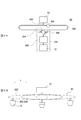
- FIG. 1A and 1B are diagrams illustrating an example of a configuration of a printing apparatus 10 according to an embodiment of the present invention.
- FIG. 1A shows an example of a configuration of a main part of the printing apparatus 10.
- FIG. 1B shows an example of a detailed configuration of the inkjet head 12 in the printing apparatus 10.
- 2A and 2B are diagrams illustrating an example of a specific configuration of the ink supply path 20.
- FIG. 2A shows an example of the configuration of the ink supply path 20.
- FIG. 2B shows an example of the state of the ink supply path 20 during the main scanning operation.
- 3A, FIG. 3B, and FIG. 3C are diagrams illustrating an example of a more specific configuration and operation of the flow path blocking unit 306.
- 3A is a cross-sectional view of the flow path blocking unit 306 in a state where the acceleration of the inkjet head 12 in the main scanning direction is zero.
- 3B and 3C are cross-sectional views of the flow path blocking unit 306 when the inkjet head 12 is accelerated or decelerated.
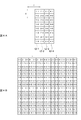
- 4A and 4B are diagrams for explaining an example of the main scanning operation performed by the plurality of inkjet heads 12.
- FIG. 4A shows an example of the configuration of the plurality of inkjet heads 12-1, 12-2, 12-3, and 12-4.
- FIG. 4B is a diagram illustrating an example of the main scanning operation in this example. It is a figure which shows an example of the speed change of the inkjet head 12 at the time of main scanning operation
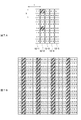
- FIG. 6A and 6B are diagrams for describing a modification of the configuration of the printing apparatus 10.
- FIG. 6A shows an example of the configuration of a plurality of inkjet heads 12 in this modification.
- FIG. 6B shows an example of the main scanning operation in this modification.
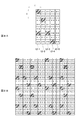
- 7A and 7B are diagrams illustrating a first example of nozzle recovery processing.
- FIG. 7A is a diagram illustrating an example of the position of a nozzle in which a discharge abnormality has occurred when a discharge abnormality has occurred in only one inkjet head 12 nozzle.
- FIG. 7B shows an example of the main scanning operation performed in this case.
- 8A and 8B are diagrams illustrating a second example of nozzle recovery processing.
- FIG. 8A is a diagram illustrating an example of the position of a nozzle in which a discharge abnormality has occurred when a discharge abnormality has occurred in the nozzles of the plurality of inkjet heads 12.
- FIG. 8B shows an example of the main scanning operation performed in this case.
- 9A and 9B are diagrams illustrating an example of a configuration when printing is performed using a plurality of colors of ink.
- FIG. 9A shows a first example of a configuration in which printing is performed using a plurality of colors of ink.
- FIG. 9B shows a second example of a configuration in which printing is performed using a plurality of colors of ink.
- FIG. 1A and 1B show an example of the configuration of a printing apparatus 10 according to an embodiment of the present invention.
- FIG. 1A shows an example of a configuration of a main part of the printing apparatus 10.
- FIG. 1B shows an example of a detailed configuration of the inkjet head 12 in the printing apparatus 10.
- the printing apparatus 10 is an ink jet printer that performs printing by an ink jet method, and includes a plurality of ink jet heads 12 (12-1, 12-2, 12-3, 12-4), a main scanning drive unit 14, and a sub scanning unit.
- a scanning drive unit 16, an ink tank 18, an ink supply path 20, and a control unit 22 are provided.
- the printing apparatus 10 When printing is performed using a plurality of color inks (for example, CMYK inks), the printing apparatus 10 includes a plurality of inkjet heads for each color, for example. A more specific configuration when printing using a plurality of colors of ink will be described in more detail later. Except as described below, the printing apparatus 10 may have the same or similar configuration as a known inkjet printer. For example, in addition to the main part shown in FIG. 1A, various configurations that are the same as or similar to those of a known inkjet printer may be further provided.
- the plurality of inkjet heads 12-1, 12-2, 12-3, and 12-4 are inkjet heads that respectively eject ink droplets of the same color ink, and are set in a main scanning direction set in advance (Y direction in the figure). ) Are arranged side by side.
- Each inkjet head 12 has a nozzle row in which a plurality of nozzles 202 are arranged in the sub-scanning direction (X direction in the drawing) orthogonal to the main scanning direction, as shown in FIG. 1B. Further, the plurality of inkjet heads 12 are arranged side by side in the main scanning direction so that the positions of the nozzles 202 in the nozzle row are aligned in the sub scanning direction.
- the inkjet head is a configuration corresponding to a portion including one nozzle row in which nozzles are arranged in the sub-scanning direction, for example. Therefore, for example, when using an inkjet head or the like in which a plurality of nozzle rows are formed on one nozzle plate, the inkjet head can be regarded as a plurality of inkjet heads that are distinguished for each nozzle row. .
- the ink used in the inkjet head 12 various known inks can be used.
- a UV ink that is cured by irradiation with ultraviolet rays a solvent UV ink obtained by diluting a UV ink with an organic solvent, or the like can be preferably used.
- solvent ink, latex ink, etc. can be used suitably.
- the printing apparatus 10 further includes a configuration for fixing the ink on the medium according to the type of ink to be used, for example.
- the printing apparatus 10 further includes an ultraviolet irradiation device.
- the printing apparatus 10 when ink that needs to be dried (solvent UV ink, solvent ink, latex ink, or the like) is used, the printing apparatus 10 further includes a heater, for example.
- the main scanning driving unit 14 is a driving unit that causes the plurality of inkjet heads 12 to perform a main scanning operation of ejecting ink droplets while moving in the main scanning direction.
- the main scanning drive unit 14 includes a guide rail 102 and a carriage 104.
- the guide rail 102 is a rail-like member extending in the main scanning direction, and holds the carriage 104 so as to be able to travel in the main scanning direction.
- the carriage 104 is a holding unit that holds a plurality of inkjet heads 12 so as to face a medium 50 to be printed. The carriage 104 moves along the guide rail 102 in accordance with an instruction from the control unit 22 to move the plurality of inkjet heads 12 in the main scanning direction.
- the main scanning drive unit 14 causes the plurality of inkjet heads 12 to eject ink droplets by, for example, transmitting an instruction from the control unit 22 to the plurality of inkjet heads 12. Thereby, the main scanning drive unit 14 causes the plurality of inkjet heads 12 to perform a main scanning operation.
- the main scanning operation performed by the plurality of inkjet heads 12 will be described in more detail later.
- the sub-scanning driving unit 16 is a driving unit that causes the plurality of inkjet heads 12 to perform a sub-scanning operation for changing the position at which the main scanning operation is performed on the medium 50, and is relative to the medium 50 in the sub-scanning direction.
- a plurality of inkjet heads 12 are moved to Further, in this example, the sub-scanning drive unit 16 is a roller that conveys the medium 50, and causes the plurality of inkjet heads 12 to perform a sub-scanning operation by moving the medium 50 side.
- the plurality of inkjet heads 12 may be caused to perform a sub-scanning operation by moving the plurality of inkjet heads 12 side.
- the sub-scanning drive unit 16 sequentially changes the area where the next main-scanning operation is performed on the medium 50 by causing the plurality of inkjet heads 12 to perform the sub-scanning operation between the main-scanning operations, for example. Accordingly, the printing apparatus 10 repeats the main scanning operation to perform printing on each position on the medium 50. Therefore, according to this example, it is possible to appropriately perform printing on the medium 50 by the serial method in which the inkjet head 12 is scanned.
- the ink tank 18 is an ink storage unit that stores ink at positions separated from the plurality of inkjet heads 12.
- the ink tank 18 is installed at a position higher than the plurality of inkjet heads 12 in the direction of gravity, and supplies ink to the plurality of inkjet heads 12 via the ink supply path 20.
- the ink supply path 20 is an ink path for supplying ink from the ink tank 18 to the plurality of inkjet heads 12. A more specific configuration of the ink supply path 20 will also be described in more detail later.
- the control unit 22 is a CPU of the printing apparatus 10, for example, and controls the operation of each unit of the printing apparatus 10 to cause the printing apparatus 10 to perform printing.
- FIG. 2A and 2B show an example of a specific configuration of the ink supply path 20.
- FIG. 2A shows an example of the configuration of the ink supply path 20.
- FIG. 2B shows an example of the state of the ink supply path 20 during the main scanning operation.
- the ink supply path 20 includes an annular tube 302, a tubing pump 304, a flow path blocking unit 306, and a pressure damper 308 between the ink tank 18 and the plurality of inkjet heads 12.
- the annular tube 302 is an annular tube having an ink introduction portion 402 into which ink is introduced from the ink tank 18 side, and an ink discharge portion 404 that discharges ink to the plurality of inkjet heads 12 side. At least a part of the ink flow path to the inkjet head 12 is formed.
- the annular tube 302 is formed of a flexible material so as to be deformed according to the movement of the plurality of inkjet heads 12 during the main scanning operation. Furthermore, in this example, the annular tube 302 is formed to a length that allows the plurality of inkjet heads 12 to move over the entire printing range in the main scanning direction.
- the ink supply path 20 supplies ink to the inkjet head 12 at each position in the main scanning direction.
- the annular tube 302 includes a tube constituting one half of the ring and a tube constituting the other half of the positions of the ink introduction part 402 and the ink discharge part 404. It has a shape connected by. Further, the tubes on one side and the other side of the ring swell in a direction away from the ink introduction unit 402 and the ink discharge unit 404 in the main scanning direction. The lengths of the tubes on one side and the other side of the ring are preferably substantially the same.
- the tubing pump 304 is a pump that circulates ink in the annular tube 302, and is disposed between the ink introduction part 402 and the ink discharge part 404 in the annular tube 302, so that the ink tank together with the annular tube 302 and the like. An ink flow path from 18 to the plurality of inkjet heads 12 is formed. Further, in this example, the tubing pump 304 opens a flow path when the plurality of inkjet heads 12 move in the main scanning direction in the main scanning operation, and allows the ink to pass through the tubing pump 304 along the annular tube 302. To. Accordingly, for example, when the ink in the annular tube 302 receives an inertial force due to acceleration or deceleration of the plurality of inkjet heads 12, the ink is circulated along the annular tube 302 according to the inertial force.
- the flow path blocking unit 306 is a blocking unit that blocks the ink flow path from the ink tank 18 to the plurality of inkjet heads 12 according to a predetermined condition.
- the flow path blocking unit 306 blocks the ink flow path when the plurality of inkjet heads 12 are accelerated and decelerated.
- the time of acceleration of the plurality of inkjet heads 12 is, for example, the timing at which the plurality of inkjet heads 12 accelerate in the main scanning direction in each of the forward path and the return path of the main scanning operation.
- the time of deceleration of the plurality of inkjet heads 12 is, for example, the timing at which the plurality of inkjet heads 12 decelerate in the main scanning direction at the end of each main scanning operation.
- the flow path blocking unit 306 is an acceleration damper that closes the ink flow path in accordance with the acceleration, and is mounted on the carriage 104 between the ink discharge unit 404 of the annular tube 302 and the inkjet head 12. It is arranged. As a result, during the main scanning operation, the flow path blocking unit 306 moves in the main scanning direction together with the inkjet head 12. A more specific configuration of the flow path blocking unit 306 will be described in detail later.
- the pressure damper 308 is a pressure regulator that adjusts the pressure of the ink supplied from the annular tube 302 to the plurality of inkjet heads 12 to a negative pressure within a certain range, and by generating a negative pressure in the plurality of inkjet heads 12, Ink is prevented from continuously leaking from the nozzles of the inkjet head 12.
- the pressure damper 308 preferably generates a negative pressure of about ⁇ 4 kPa to 0 kPa with respect to the atmospheric pressure, for example, in each of the plurality of inkjet heads 12 as the negative pressure.
- the pressure damper 308 is disposed between the flow path blocking unit 306 and the inkjet head 12 in the ink flow path. According to this example, ink can be appropriately supplied to the inkjet head 12. In the modified example of the configuration of the ink supply path 20, the pressure damper 308 may be disposed between the ink discharge unit 404 and the flow path blocking unit 306, for example.
- ink may be supplied to the plurality of inkjet heads 12 through one ink supply path 20.
- the ink supply path 20 may include, for example, a flow path blocking unit 306 and a pressure damper 308 for each inkjet head 12.
- the ink supply path 20 supplies ink to each of the plurality of inkjet heads 12 via the flow path blocking unit 306 and the pressure damper 308 provided individually for each inkjet head 12.
- the ink supply path 20 may supply ink to the plurality of inkjet heads 12 via a set of flow path blocking units 306 and a pressure damper 308.
- FIG. 3A is a cross-sectional view of the flow path blocking unit 306 in a state where the acceleration of the inkjet head 12 in the main scanning direction is zero.
- FIGB and 3C are cross-sectional views of the flow path blocking unit 306 when the inkjet head 12 is accelerated or decelerated.
- the flow path blocking unit 306 includes a storage unit 412, connection portions 416a and 416b, and a spherical body 414.
- the accommodating portion 412 is a hollow body that accommodates the spherical body 414 therein.
- the storage portion 412 has a shape in which the central portion in the direction along the ink flow path swells up and down in the direction of gravity.
- the accommodating portion 412 has an opening 502 through which ink flows along the ink flow path on one side and the other side of the ink flow path, and is provided at a position in the middle of the ink flow path. Thus, a part of the ink flow path is formed.
- the opening 502 on one side in the ink flow path is connected to the annular tube 302 via the connection portion 416a. Further, the opening 502 on the other side is connected to the inkjet head 12 via a connection portion 416b and a pressure damper 308 (see FIGS. 2A and 2B).
- connection portions 416a and 416b are portions that connect the flow path blocking unit 306 to the ink flow paths.
- the connection portion 416a is a connection portion on the annular tube 302 side in the ink flow path.
- connection portion 416b is a connection portion on the ink jet head 12 side in the ink flow path.
- the spherical body 414 is an example of a moving member, and can move through the hollow portion of the storage portion 412 along the ink flow path, and does not pass through the openings 502 on one side and the other side of the storage portion 412.
- the spherical body 414 moves along the ink flow path according to the inertial force generated in the ink flow path when the inkjet head 12 is accelerated and decelerated during the main scanning operation.
- the movement of the spherical body 414 according to the inertial force may be, for example, a movement according to the pressure of the ink that moves due to the inertial force.
- the spherical body 414 closes any opening of the storage portion 412 and blocks the ink flow path.
- the accommodating portion 412 of this example has a shape in which the central portion swells up and down in the direction of gravity. Therefore, in a state where the inertial force is not received, the spherical body 414 is positioned at the center of the accommodating portion 412 as shown in FIG. 3A due to its own weight. As a result, the flow path blocking unit 306 does not block the ink flow path.
- the state in which the spherical body 414 does not receive the inertial force is a state in which the acceleration of the inkjet head 12 is zero, and more specifically, for example, when the inkjet head 12 is stationary, or This is the case when the head 12 is moving at a constant speed. Therefore, according to this example, for example, when the inkjet head 12 is stationary or while the inkjet head 12 is moving at a constant speed in the main scanning operation, the flow path blocking unit 306 opens the ink flow path.
- the flow path blocking unit 306 blocks the ink flow path during acceleration and deceleration in the main scanning operation.
- FIG. 3B shows a cross-sectional view of the flow path blocking unit 306 in a state where the spherical body 414 receives the inertial force in the direction of the arrow 504.
- This state is, for example, a state where the inkjet head 12 is decelerated while moving in the direction of the arrow 504, or a state where the inkjet head 12 is accelerating while moving in the direction opposite to the arrow 504.
- the spherical body 414 moves to the left in the figure in accordance with the inertial force, and closes the opening 502 on one side. Accordingly, the flow path blocking unit 306 blocks the ink flow path.
- FIG. 3B shows a cross-sectional view of the flow path blocking unit 306 in a state where the spherical body 414 receives the inertial force in the direction of the arrow 506.
- This state is, for example, a state where the inkjet head 12 is decelerating while moving in the direction of the arrow 506, or a state where the inkjet head 12 is accelerating while moving in the direction opposite to the arrow 506.
- the spherical body 414 moves to the right side in the figure according to the inertial force, and closes the opening 502 on the other side. Accordingly, the flow path blocking unit 306 blocks the ink flow path.
- the ink flow path can be appropriately blocked at each of acceleration and deceleration of the inkjet head 12 in the main scanning operation.
- fluctuations in pressure applied to the inkjet head 12 from the ink supply path 20 can be appropriately suppressed.
- blocking the ink flow path during acceleration and deceleration refers to, for example, the absolute value of acceleration during acceleration and deceleration from a predetermined value depending on the sensitivity determined according to the shape of the flow path blocking section 306 and the like. May also be to block the flow path. Moreover, about the sensitivity of interruption
- the ink jet head 12 when the ink jet head 12 is accelerated or decelerated, the ink in the ink jet head 12 and the ink contained in the portion that moves together with the ink jet head 12 in the ink supply path 20 are affected by the acceleration. .
- the ink moves, and pressure fluctuations may occur in the inkjet head 12, the ink supply path 20, or the like. As a result, there may be a problem in the state of the inkjet head 12.
- the ink supply path 20 is not configured so as to suppress pressure fluctuation
- the acceleration is large when the inkjet head 12 is accelerated, air is drawn from the nozzle, so-called “missing out”. Problems may arise.
- the acceleration absolute value of acceleration
- the ink may spill out from the nozzles, which may cause a problem of so-called dropping.
- the ink supply path 20 further includes an annular tube 302 in addition to the flow path blocking section 306 as a configuration for suppressing pressure fluctuation due to inertial force during acceleration and deceleration.
- annular tube 302 when the annular tube 302 is used, for example, when the ink jet head 12 is accelerated and decelerated, even if the ink in the ink supply path moves due to the acceleration, the ink circulates in the annular tube 302. Is unlikely to occur. Therefore, according to the present example, for example, when the inkjet head 12 is accelerated and decelerated, fluctuations in pressure applied from the ink supply path 20 to the inkjet head 12 can be more appropriately suppressed. In addition, for example, it is possible to more appropriately prevent problems such as missing and dropping.
- 4A and 4B are diagrams for explaining an example of the main scanning operation performed by the plurality of inkjet heads 12.
- a case where four inkjet heads 12-1, 12-2, 12-3, and 12-4 are used as the plurality of inkjet heads 12 will be described.
- the number of nozzles arranged in each nozzle row of the inkjet heads 12-1, 12-2, 12-3, 12-4 is assumed to be eight.
- FIG. 4A shows an example of the configuration of a plurality of inkjet heads 12-1, 12-2, 12-3, and 12-4.
- numerals i-1, i-2, i-3, i-4, i-5, drawn in the inkjet head 12-i i is any one of 1, 2, 3, 4
- i-6, i-7, and i-8 indicate the 1st to 8th nozzles in the nozzle row of the inkjet head 12-i.
- the plurality of inkjet heads 12-1, 12-2, 12-3, 12-4 are sub-scanned in the nozzle row in the nozzle row.
- the positions are aligned so as to be aligned in the direction, and are arranged in the main scanning direction. Therefore, as shown in the figure, the first nozzles 1-1, 2-1, 3-1, 4-1 in each of the inkjet heads 12-1, 12-2, 12-3, 12-4 are The positions in the sub-scanning direction are aligned and aligned in the main scanning direction.
- the j-th nozzle 1 (j is any one of 2, 3, 4, 5, 6, 7, 8) in each of the inkjet heads 12-1, 12-2, 12-3, 12-4.
- j, 2-j, 3-j, and 4-j are aligned in the main scanning direction with their positions in the sub-scanning direction aligned.
- FIG. 4B is a diagram showing an example of the main scanning operation in this example, and relates to an example of an arrangement of ink dots formed on the medium by the inkjet heads 12-1, 12-2, 12-3, and 12-4. For each position on the medium, a nozzle that forms an ink dot at that position is shown. For convenience of illustration, in FIG. 4B, when only one main scanning operation is performed on each area on the medium (when printing is performed in one pass), the sub-scanning operation is sandwiched 2 The nozzles for forming ink dots at each position are shown for the number of main scanning operations.
- the plurality of inkjet heads 12-1, 12-2, 12-3, 12-4 are arranged in a row of dots in which ink dots are aligned in the main scanning direction with the positions in the sub scanning direction aligned by the main scanning operation.
- a dot row is a row in which ink dots are formed by ink droplets landing on a medium.
- the ink dots constituting the dot row formed by each main scanning operation are formed by a plurality of inkjet heads 12-1, 12-2, 12-3, 12-4. . Accordingly, a dot row in which ink dots are arranged in the main scanning direction is formed by a plurality of nozzles of the same color.
- the plurality of inkjet heads 12-1, 12-2, 12-3, 12-4 form dot rows so that adjacent ink dots are formed by different inkjet heads in the main scanning direction.
- To do for example, by forming adjacent ink dots in the main scanning direction with different nozzles, it is possible to appropriately prevent adjacent ink dots formed in the same nozzle in the main scanning direction. be able to. Therefore, according to this example, for example, regarding the ejection characteristics of the nozzles, it is not possible to use the multi-pass method.
- a method (pseudo multi-pass scanning) that obtains the same effect as the multi-pass method can be realized. Thereby, for example, occurrence of banding can be appropriately suppressed.
- the ink dots formed by the same nozzle are not adjacent not only in the main scanning direction but also in the sub-scanning direction and the oblique direction. If comprised in this way, the discharge characteristic of a nozzle can be averaged more appropriately, for example.
- the nozzle discharge characteristics are averaged by the multi-pass method, it is necessary to perform a sub-scanning operation between a plurality of main scanning operations performed on the same region.
- the position of the ink dot formed in each main scanning operation may be shifted due to an error in the amount of movement during the sub-scanning operation.
- such a shift does not occur. Therefore, according to this example, for example, high-precision printing can be performed more appropriately.
- the multi-pass printing is performed for the purpose of increasing the resolution in addition to averaging the discharge characteristics of the nozzles. Therefore, in the printing apparatus 10 of this example, printing in the multipass method may be performed for the purpose of increasing the resolution. In this case as well, since the ejection characteristics of the nozzles can be averaged by the pseudo multi-pass method, the necessary number of passes can be appropriately reduced. For example, when printing is performed at a resolution with a dot density corresponding to half the nozzle pitch in the inkjet head, the number of printing passes can be reduced to two.
- the number of printing passes is usually set to 8 or more in order to perform printing with sufficient quality. is required.
- the number of printing passes is usually set to 8 or more in order to perform printing with sufficient quality.
- printing can be appropriately performed with two passes. it can.
- the ink supply path for supplying ink to the inkjet head 12 is an annular tube 302 (see FIGS. 2A and 2C). 2B) and the flow path blocking unit 306 (see FIGS. 2A and 2B), the pressure applied to the inkjet head 12 from the ink supply path during acceleration and deceleration of the inkjet head in the main scanning direction. It is configured to suppress fluctuations. Therefore, in each main scanning operation, useless time during acceleration and deceleration can be shortened, and the moving speed of the inkjet head 12 during the main scanning operation can be increased.
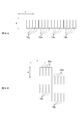
- FIG. 5 shows an example of a change in speed of the inkjet head 12 during the main scanning operation.
- ink droplets are usually ejected by supplying a drive signal having a predetermined waveform to each nozzle.
- Each nozzle ejects ink droplets by vibrating the ink meniscus in accordance with the drive signal. Therefore, when ink droplets are continuously ejected from one nozzle during the main scanning operation, it is necessary to match the ejection cycle with the cycle for appropriately vibrating the meniscus.
- the moving speed of the ink-jet head during the main scanning operation needs to be determined according to the printing resolution and the cycle for appropriately vibrating the meniscus (hereinafter referred to as the drive signal cycle). Become.
- the main scanning operation is performed using only one inkjet head, and each of the components on the medium is used without using the multi-pass method.
- the nozzles of the inkjet head it is necessary for the nozzles of the inkjet head to eject ink droplets to respective positions arranged at dot intervals according to the printing resolution while moving in the main scanning direction. Accordingly, in this case, it is necessary to slow down the moving speed of the ink jet head so that the time during which the ink jet head moves at least as much as between adjacent dots is longer than the cycle of the drive signal.
- the waveform shown by the broken line shows an example of the moving speed of the inkjet head in such a case.
- the inkjet head performs the main scanning operation while moving at a constant speed v1.
- the time required to accelerate from the stop state to the speed v1 is t1. Further, the time required to decelerate from the speed v1 to the stop state is also t1.
- the moving speed during the main scanning operation can be increased.
- the dots in the dot row in which the ink dots are arranged in the main scanning direction are formed by being shared by the four nozzles.
- ink dots may be formed at a rate of one dot for every four dots in the dot row.
- the interval in the main scanning direction of the ink dots formed by one nozzle can be four times that when only one ink jet head is used. Therefore, when four inkjet heads 12-1, 12-2, 12-3, and 12-4 are used, for example, regarding the moving speed of the inkjet head, the time for which the inkjet head moves by 4 dots is longer than the cycle of the drive signal. May be set to be longer.
- the waveform indicated by the solid line shows an example of the moving speed of each inkjet head when four inkjet heads 12-1, 12-2, 12-3, and 12-4 are used.
- the moving speed of the inkjet head 12 during the main scanning operation can be appropriately increased.
- the loss time required for acceleration and deceleration also increases if the acceleration during acceleration / deceleration does not change. As a result, the printing speed may not be sufficiently increased.
- the time required for acceleration / deceleration is one as indicated by a dashed line in the figure.
- T2 4t1 which is four times that when only the inkjet head is used. Therefore, in this case, the influence of the loss time on the printing speed is increased, and there is a possibility that the printing speed cannot be sufficiently increased.
- ink is supplied to the inkjet head 12 using an ink tank provided at a position separated from the inkjet head 12.
- Such a configuration is often used in, for example, a large ink jet printer.
- a large inkjet printer it is desired to increase the moving speed of the inkjet head during the main scanning operation in order to perform printing on a large medium.
- the moving speed of the inkjet head even when the moving speed of the inkjet head is increased, the loss time can be appropriately reduced. Also, the number of printing passes can be appropriately reduced. Therefore, according to this example, for example, even in a large-scale ink jet printer, the moving speed of the ink jet head during the main scanning operation can be appropriately increased, and high-speed printing can be more appropriately realized.
- FIGS. 1A and 1B are diagrams for describing a modification of the configuration of the printing apparatus 10 and show an example of the configuration and operation in the case where a larger number of inkjet heads 12 are used. Except as described below, the configuration and operation of this modification are as shown in FIGS. 1A and 1B, FIGS. 2A and 2B, FIGS. 3A, 3B and 3C, FIGS. 4A and 4B, and FIGS. This is the same as or similar to the printing apparatus 10 described with reference to FIG.
- FIG. 6A shows an example of the configuration of a plurality of inkjet heads 12 (12-1, 12-2, 12-3, 12-4, 12-5) in this modification.
- FIG. 6B shows an example of the main scanning operation in this modification.
- a pseudo multi-pass that obtains the same effect as the multi-pass method with the number of passes of (N ⁇ 1) or less by N (N is an integer of 3 or more) inkjet heads.
- N is an integer of 3 or more
- N inkjet heads as a plurality of inkjet heads that respectively eject ink droplets of the same color ink.
- N is an integer of 2 or more and N ⁇ 1 or less
- Select k inkjet heads is changed every time k k dots of the ink arranged in the main scanning direction are formed.
- the printing apparatus 10 includes five inkjet heads 12-1, 12-2, 12-3, 12-4, and 12-5, as shown in FIG. 6A.
- the inkjet heads 12-1, 12-2, 12-3, 12-4, and 12-5 In each main scanning operation, among the five inkjet heads 12-1, 12-2, 12-3, 12-4, and 12-5, the inkjet heads that form four consecutive dots are used. Select four. Further, every time four dots arranged in the main scanning direction are formed, the four inkjet heads 12 to be selected are changed.
- the inkjet heads 12 to be used are sequentially changed during the main scanning operation. Thereby, for example, nozzles that eject ink droplets can be uniformly distributed. Further, it is possible to make it difficult for nozzle clogging and the like to occur due to suspension of discharge.
- printing is performed by selecting a smaller number of inkjet heads than the total number at each timing of the main scanning operation. For example, an abnormality occurs in the ejection characteristics of any nozzle of the inkjet head 12. In some cases, for example, printing can be continued by performing printing only with the inkjet head 12 other than the inkjet head 12 having the nozzle. Therefore, according to this modification, for example, it is possible to provide a high-performance printing apparatus that is highly resistant to failures and the like.
- the inkjet head 12 having a failed nozzle is not used, the number of inkjet heads 12 used at each timing of the main scanning operation does not change. Therefore, it is not necessary to reduce the moving speed of the inkjet head 12 during the main scanning operation. Accordingly, according to the present modification, for example, nozzle recovery processing that avoids the use of a failed nozzle can be appropriately performed without reducing the printing speed.
- nozzle recovery process various methods are possible depending on, for example, the position of the nozzle where the ejection abnormality has occurred. Therefore, an example of nozzle recovery processing will be described below.
- FIGS. 7A and 7B are diagrams for explaining a first example of the nozzle recovery process, and shows an example of the nozzle recovery process when an ejection abnormality occurs in the nozzle of only one inkjet head 12.
- FIG. 7A is a diagram illustrating an example of the position of the nozzle in which the ejection abnormality has occurred in the case where ejection abnormality has occurred in the nozzle of only one inkjet head 12, and the first and fifth positions in the nozzle row of the inkjet head 12-2. This shows a state in which a discharge abnormality has occurred in the second nozzle (2-1, 2-5).
- FIG. 7B shows an example of the main scanning operation performed in this case.
- the printing apparatus 10 when a discharge abnormality occurs in the nozzle of only one inkjet head 12-2, the printing apparatus 10 causes the other inkjet heads 12-1, 12-3, 12-4, 12-5 to be used. Is used to perform the main scanning operation.
- the inkjet head 12 having the nozzles where the ejection characteristics are abnormal can be used appropriately without using them. Can be printed.
- by appropriately performing the nozzle recovery process for example, it is possible to appropriately provide a high-performance printing apparatus 10 that is highly resistant to failure or the like.
- the number of inkjet heads 12 included in the printing apparatus 10 is N, for example, in any nozzle of any inkjet head 12.
- N for example, in any nozzle of any inkjet head 12
- this is a process of forming a dot row.
- the nozzle recovery process can also be performed when, for example, a discharge abnormality has occurred in the nozzles of the plurality of inkjet heads 12. Therefore, hereinafter, the nozzle recovery process will be described as a second example of the nozzle recovery process.
- FIGS. 8A and 8B are diagrams for explaining a second example of the nozzle recovery process, and shows an example of the nozzle recovery process when ejection abnormality occurs in the nozzles of the plurality of inkjet heads 12.
- FIG. 8A is a diagram illustrating an example of the position of the nozzle where the ejection abnormality has occurred when ejection abnormality occurs in the nozzles of the plurality of inkjet heads 12, and the first and sixth positions in the nozzle row of the inkjet head 12-1.
- FIG. 8B shows an example of the main scanning operation performed in this case.
- the nozzles of the inkjet head 12 other than the inkjet head 12 having the abnormal nozzle are formed.
- the other inkjet heads 12 are selected from a plurality of inkjet heads 12 other than the inkjet heads 12 adjacent to the inkjet head 12 having abnormal nozzles in the main scanning direction.
- the abnormal nozzle is, for example, a nozzle in which an abnormality has occurred in the ejection characteristics.
- the ink dots to be formed by the abnormal nozzle are, for example, ink dots that should be originally formed by the nozzle when the ejection characteristics of the nozzle that has become the abnormal nozzle are not abnormal.
- the nozzles of the other inkjet heads 12 are selected from, for example, nozzles that have the same positions in the sub-scanning direction as the corresponding abnormal nozzles.
- the ink dots to be formed by the nozzle 1-1 which is an abnormal nozzle in the inkjet head 12-1, are replaced with the normal nozzles 4 in the other inkjet heads 12-4. -1.
- ink dots to be formed by other abnormal nozzles are also formed by normal nozzles in the other inkjet heads 12, respectively.
- the codes (1-1, etc.) indicating the corresponding abnormal nozzles are erased by strike-through lines for the positions of some of the dots. Is shown. Further, the reference numeral (4-1) or the like indicating a nozzle to be used instead is also written for the position. However, for convenience of illustration, only the corresponding abnormal nozzle codes are shown for the positions of the dots except for some of the ink dots to be formed by the abnormal nozzles.
- FIGS. 1A and 1B a modified example of the configuration of the printing apparatus 10
- FIGS. 2A and 2B a more specific configuration in the case where printing is performed using a plurality of colors of ink will be described.
- the configuration and operation in this modification are as shown in FIGS. 1A and 1B, FIGS. 2A and 2B, FIGS. 3A, 3B and 3C, FIGS. 4A and 4B, and FIGS.
- FIGS. 6A and 6B FIGS. 7A and 7B, FIGS. 8A and 8B.
- FIG. 9A and FIG. 9B show examples of configurations when printing is performed using a plurality of colors of ink.
- FIG. 9A shows a first example of a configuration in which printing is performed using a plurality of colors of ink.
- FIG. 9B shows a second example of a configuration in which printing is performed using a plurality of colors of ink.
- the printing apparatus 10 When printing using a plurality of colors of ink, the printing apparatus 10 includes a plurality of inkjet heads 12 arranged in the main scanning direction for each of the plurality of colors.
- the printing apparatus 10 includes a plurality of Y (yellow) color inkjet heads 12y, a plurality of M (magenta) color inkjet heads 12m, and C (cyan).
- a plurality of inkjet heads 12c for color and a plurality of inkjet heads 12k for K (black) color are provided.
- the ink jet heads 12 of these colors are arranged side by side in the main scanning direction.
- the inkjet heads 12 of these colors are arranged side by side in the sub-scanning direction.
- the position in the main scanning direction may also be shifted for each color.
- color printing can be performed appropriately by performing printing using inks of a plurality of colors.
- the discharge characteristics of the nozzles can be appropriately averaged for the plurality of inkjet heads 12 of each color in the same manner as the printing apparatus 10 described with reference to FIGS. 1A and 1B and the like. Therefore, also in this modification, for example, the number of passes required for printing can be appropriately reduced.
- the same effects as those of the printing apparatus 10 described with reference to FIGS. 1A and 1B and the like can be obtained for printing with ink of each color.
- the present invention can be suitably used for a printing apparatus, for example.
Landscapes
- Ink Jet (AREA)
Abstract
印刷に必要なパス数を適切に低減することを課題とする。 解決手段として、インクジェット方式で印刷を行う印刷装置(10)であって、同一色のインクのインク滴をそれぞれ吐出する複数のインクジェットヘッドであり、主走査方向へ並べて配設された複数のインクジェットヘッド(12)と、主走査駆動部(14)と、副走査駆動部(16)とを備え、複数のインクジェットヘッド(12)は、主走査動作により、インク滴が媒体に着弾することで形成されるインクのドットが並ぶ列であり、副走査方向における位置を揃えて主走査方向へインクのドットが並ぶドット列を形成し、かつ、主走査方向において隣接するインクのドットを異なるインクジェットヘッド(12)で形成するように、ドット列を形成する。
Description
本発明は、印刷装置及び印刷方法に関する。
従来、インクジェット方式で印刷を行うインクジェットプリンタが広く用いられている(例えば、非特許文献1参照。)。インクジェットプリンタは、インクジェットヘッドに形成されたノズルからインク滴を吐出することにより、媒体(メディア)に対して印刷を行う。
また、インクジェットプリンタにおいては、インクジェットヘッドに主走査動作を行わせるシリアル方式のインクジェットプリンタが広く用いられている。また、シリアル方式のインクジェットプリンタでは、マルチパス方式での印刷が広く行われている。この場合、マルチパス方式での印刷とは、媒体上の同じ領域上で複数回の主走査動作を行うことで印刷を行うことである。また、主走査動作とは、インクジェットヘッドが所定の主走査方向へ移動しつつインク滴を吐出する動作である。
インターネットURL http://www.mimaki.co.jp
シリアル方式のインクジェットプリンタは、複数回の主走査動作を行うことにより、媒体への印刷を行う。また、各回の主走査動作においては、停止状態のインクジェットヘッドを主走査方向へ加速し、その後、一定の速度でインクジェットヘッドを主走査方向へ移動させる。また、各回の主走査動作の最後には、インクジェットヘッドが停止するまで、インクジェットヘッドの速度を減速する。
しかし、この動作において、媒体へインク滴を吐出するのは、一定の速度でインクジェットヘッドを主走査方向へ移動させている間のみである。そのため、主走査動作時におけるインクジェットヘッドの加速及び減速のために要する時間は、実際にインク滴を吐出している時間以外の無駄な時間(ロス時間)となる。そのため、インクジェットヘッドの加速及び減速のために要する時間は、できるだけ少なくすることが望ましい。
しかし、マルチパス方式で印刷を行う場合、パス数が多くなると、パス数に応じて、主走査動作の回数も多くなる。また、これに伴い、インクジェットヘッドの加速及び減速を行う回数も多くなる。そのため、マルチパス方式で印刷を行う場合において、パス数が多くなると、ロス時間の影響で印刷に要する時間が増大し、印刷速度が大幅に低下するおそれがある。そこで、本発明は、上記の課題を解決できる印刷装置及び印刷方法を提供することを目的とする。
シリアル方式のインクジェットプリンタにおいては、通常、インクジェットヘッドのノズルの吐出特性の平均化や、高解像度化を行う目的で、マルチパス方式での印刷を行う。ノズルの吐出特性の平均化とは、例えば、各回の主走査動作の合間に副走査動作を行うことにより、媒体上の同じ領域上で行う複数回の主走査動作においてその領域へインク滴を吐出するノズルを異ならせ、その領域へインク滴を吐出するノズルの吐出特性を平均化することである。副走査動作とは、主走査方向と直交する副走査方向へ、媒体に対して相対的にインクジェットヘッドを移動させる動作である。
また、マルチパス方式による高解像度化とは、マルチパス方式で印刷を行うことにより、副走査方向における解像度について、インクジェットヘッドにおけるノズルのピッチよりも狭いドット密度(dpi)の解像度で印刷を行うことである。この場合、インクジェットヘッドにおけるノズルのピッチとは、インクジェットヘッドにおいて副走査方向へ複数のノズルが並ぶノズル列における、ノズルの間隔である。マルチパス方式による高解像度化は、例えば、1回の副走査動作において媒体に対して相対的にインクジェットヘッドを移動させる移動量の設定について、ノズルのピッチの整数倍ではなく、ノズルのピッチの整数倍から1/nピッチ(nは、2以上の整数)分だけずれた距離に設定することで行うことができる。より具体的には、例えば、1回の副走査動作におけるインクジェットヘッドの移動量を、ノズルのピッチの整数倍から1/2ピッチずれた距離に設定することにより、ノズルのピッチの1/2の距離に対応するドット密度の解像度での印刷を行うことができる。
これに対し、本願の発明者は、鋭意研究により、インクジェットヘッドのノズルの吐出特性の平均化については、マルチパス方式での印刷を行わなくても、複数のインクジェットヘッドを所定の配置で配設することで実現できることを見出した。この場合、例えば、高解像度化の目的のために必要な回数のみのパス数で印刷を行えば、高い解像度での印刷を適切に行うことができる。また、これにより、印刷に必要なパス数を適切に低減することができる。また、マルチパス方式による高解像度化が必要ない場合には、マルチパス方式での印刷を行うことなく、高い品質での印刷を適切に行うことができる。上記の課題を解決するために、本発明は、以下の構成を有する。
(構成1)インクジェット方式で印刷を行う印刷装置であって、同一色のインクのインク滴をそれぞれ吐出する複数のインクジェットヘッドであり、予め設定された主走査方向へ並べて配設された複数のインクジェットヘッドと、主走査方向へ移動しつつインク滴を吐出する主走査動作を複数のインクジェットヘッドに行わせる主走査駆動部と、主走査方向と直交する副走査方向へ媒体に対して相対的に複数のインクジェットヘッドを移動させることにより、媒体上において主走査動作が行われる位置を変更する副走査駆動部とを備え、複数のインクジェットヘッドは、主走査動作により、インク滴が媒体に着弾することで形成されるインクのドットが並ぶ列であり、副走査方向における位置を揃えて主走査方向へインクのドットが並ぶドット列を形成し、かつ、主走査方向において隣接するインクのドットを異なるインクジェットヘッドで形成するように、ドット列を形成する。
このように構成した場合、各回の主走査動作により形成されるドット列を構成するインクのドットは、複数のインクジェットヘッドにより形成されることになる。そのため、このように構成すれば、例えば、各回の主走査動作において、ノズルの吐出特性を適切に平均化することができる。
また、この場合、例えば、ノズルの吐出特性の平均化の目的で複数のパス数での印刷を行うことが必要なくなるため、印刷に必要なパス数を適切に低減できる。例えば、副走査方向の解像度について、インクジェットヘッドにおけるノズルのピッチの半分の距離に対応するドット密度の解像度で印刷を行う場合、印刷のパス数を2回に減らすこと等も可能である。また、例えば、ノズルのピッチよりも高解像度化することが不要である場合、マルチパス方式での印刷を行わず、媒体上の各領域上で1回の主走査動作のみを行うこと等も考えられる。
そのため、このように構成すれば、例えば、印刷のパス数を適切に低減できる。また、これにより、主走査動作時におけるインクジェットヘッドの加速及び減速に要するロス時間を短縮し、印刷速度を適切に向上させることができる。
(構成2)複数のインクジェットヘッドから離間した位置においてインクを貯留するインクタンクと、インクタンクから複数のインクジェットヘッドまでインクを供給するインク供給路とを更に備える。
インクジェットヘッドから離間した位置に設けたインクタンクを使用する構成は、例えば、大型のインクジェットプリンタ等において用いられる場合が多い。そして、大型のインクジェットプリンタにおいては、大型の媒体への印刷を行うために、主走査動作時のインクジェットヘッドの移動速度を高速にすることが望まれる。
しかし、主走査動作時のインクジェットヘッドの移動速度を高速にする場合、加速及び減速に要する時間も増大することになる。そのため、例えば印刷のパス数が多い場合、ロス時間が増大し、印刷速度が低下するおそれがある。これに対し、構成2のように構成した場合、印刷のパス数を適切に低減できる。また、これにより、例えば、主走査動作時のインクジェットヘッドの移動速度を高速にする場合等において、高速な印刷をより適切に実現できる。
(構成3)インク供給路は、主走査方向へインクジェットヘッドが加速する加速時、及び、主走査方向においてインクジェットヘッドが減速する減速時のそれぞれにおいて、インク供給路からインクジェットヘッドに加わる圧力の変動を抑えるように構成されている。
インク供給路からインクジェットヘッドに加わる圧力の変動とは、例えば、インクジェットヘッド内のインクに加わる圧力の変動である。この圧力の変動は、例えば、インク供給路内の圧力と、インクジェットヘッド内の圧力との差の変動により生じる。
インクジェットヘッドを加速又は減速させる場合、インクジェットヘッド内のインクや、インク供給路においてインクジェットヘッドと共に移動する部分に含まれているインクは、加速度の影響を受ける。また、これにより、インクが移動し、インクジェットヘッド内やインク供給路内等において、圧力の変動が生じる場合がある。また、その結果、インクジェットヘッドの状態に問題が生じる場合がある。
より具体的には、例えば、上記のように圧力の変動を抑えるようにインク供給路が構成されていない場合、インクジェットヘッドの加速時において、加速度が大きいと、ノズルから空気を引き込み、いわゆるドカ抜けといわれる問題が生じる場合がある。また、インクジェットヘッドの減速時において、加速度(加速度の絶対値)が大きいと、ノズルからインクが零れだし、いわゆるボタ落ちといわれる問題が生じる場合がある。これに対し、構成3のように構成すれば、インクジェットヘッドの加速時及び減速時の圧力変動により生じる問題を適切に抑えることができる。
また、これにより、例えば、加速時及び減速時の加速度の絶対値を大きくして、より短時間で加速及び減速を行うことも可能になる。そのため、このように構成すれば、例えば、主走査動作時におけるインクジェットヘッドの加速及び減速に要するロス時間を適切に低減できる。
(構成4)インク供給路は、主走査動作時におけるインクジェットヘッドの移動に応じて変形する環状チューブを含み、環状チューブは、インクタンクからインクジェットヘッドまでのインクの流路の少なくとも一部を形成しており、インクタンク側からインクが導入されるインク導入部と、インクジェットヘッド側にインクを排出するインク排出部とを有し、主走査方向における印刷範囲の全体をインクジェットヘッドが移動できる長さに形成されている。
このように構成した場合、例えば、インクジェットヘッドの加速時及び減速時において、インク供給路内のインクが加速度の影響で移動しても、環状チューブ内で循環するため、インクジェットヘッドへの影響は生じにくい。そのため、このように構成すれば、例えば、インクジェットヘッドの加速時及び減速時において、インク供給路からインクジェットヘッドに加わる圧力の変動を適切に抑えることができる。また、これにより、例えば、いわゆるドカ抜けやボタ落ちといわれる問題等が生じることを適切に防ぐことができる。
(構成5)インク供給路は、インクタンクからインクジェットヘッドまでのインクの流路を遮断する流路遮断部を含み、流路遮断部は、主走査方向へインクジェットヘッドが加速する加速時、及び、主走査方向においてインクジェットヘッドが減速する減速時のそれぞれにおいて、流路を遮断する。
このように構成した場合、例えば、インクジェットヘッドの加速時及び減速時において、インクの流路を適切に遮断できる。そのため、このように構成すれば、例えば、インクジェットヘッドの加速時及び減速時において、インク供給路からインクジェットヘッドに加わる圧力の変動を適切に抑えることができる。また、これにより、例えば、いわゆるドカ抜けやボタ落ちといわれる問題等が生じることを適切に防ぐことができる。
(構成6)主走査動作時において、流路遮断部は、インクジェットヘッドと共に主走査方向へ移動し、かつ、流路遮断部は、加速時及び減速時のそれぞれにおいてインクの流路内に生じる慣性力に応じてインクの流路に沿って移動する移動部材と、移動部材を内部に収容する中空体であり、インクの流路の途中の位置に設けられることでインクの流路の一部を形成する収容部とを有し、収容部は、インクの流路における一方側及び他方側のそれぞれに、インクの流路に沿ってインクを流す開口部と有し、移動部材は、インクの流路に沿って収容部の中空部分を移動可能であり、かつ、インクの流路における一方側及び他方側の開口部を通過しない大きさを有しており、加速時及び減速時のそれぞれにおいて、収容部のいずれかの開口部を塞ぐことにより、インクの流路を遮断する。
このように構成すれば、例えば、インクジェットヘッドの加速時及び減速時において、インクの流路を適切に遮断できる。尚、移動部材について、慣性力に応じて移動するとは、例えば、慣性力により移動するインクの圧力に応じて移動することであってよい。
(構成7)同一色のインクのインク滴をそれぞれ吐出する複数のインクジェットヘッドとして、N個(Nは、3以上の整数)のインクジェットヘッドを備え、各回の主走査動作において、主走査方向において連続して並ぶk個(kは、2以上、N-1以下の整数)のインクのドットを形成すべきインクジェットヘッドとして、N個のうちのk個のインクジェットヘッドを選択し、かつ、主走査方向において連続して並ぶk個の前記インクのドットを形成する毎に、選択するインクジェットヘッドを変更する。
このように構成した場合も、例えば、各回の主走査動作において、複数のインクジェットヘッドにより、ノズルの吐出特性を適切に平均化することができる。また、この場合、主走査動作の各タイミングにおいて、総数よりも少ない数のインクジェットヘッドを選択して印刷を行うため、例えばいずれかのインクジェットヘッドの吐出特性に異常が生じた場合等にも、他のインクジェットヘッドを用いて印刷を続行することが可能になる。そのため、このように構成すれば、例えば、故障等への耐性の高い高性能の印刷装置を提供することができる。
(構成8)同一色のインクのインク滴をそれぞれ吐出する複数のインクジェットヘッドとして、N個(Nは、3以上の整数)のインクジェットヘッドを備え、それぞれのインクジェットヘッドは、インク滴を吐出するノズルを有し、いずれかのインクジェットヘッドにおけるいずれかのノズルにおいて、インク滴の吐出特性に異常が生じた場合、各回の主走査動作において、N個のインクジェットヘッドのうち、吐出特性の異常が生じたノズルを有するインクジェットヘッドを含まない(N-1)個以下のインクジェットヘッドにより、ドット列を形成する。
このように構成すれば、例えば、いずれかのインクジェットヘッドのノズルにおいて吐出特性に異常が生じた場合等においても、吐出特性に異常が生じたインクジェットヘッドを使用することなく、適切に印刷を行うことができる。また、これにより、例えば、故障等への耐性の高い高性能の印刷装置を提供することができる。
(構成9)それぞれのインクジェットヘッドは、インク滴を吐出するノズルを有し、いずれかのインクジェットヘッドにおけるいずれかのノズルにおいて、インク滴の吐出特性に異常が生じた場合、吐出特性に異常が生じたノズルである異常ノズルにより形成すべきインクのドットを、当該異常ノズルを有するインクジェットヘッド以外の他のインクジェットヘッドのノズルにより形成し、他のインクジェットヘッドは、複数のインクジェットヘッドのうち、異常ノズルを有するインクジェットヘッドと主走査方向において隣接するインクジェットヘッド以外から選ばれる。異常ノズルにより形成すべきインクのドットとは、例えば、異常ノズルとなったノズルについて、吐出特性に異常が生じていなければ本来そのノズルで形成されるべきインクのドットのことである。
このように構成すれば、例えば、いずれかのインクジェットヘッドのノズルにおいて吐出特性に異常が生じた場合等においても、吐出異常の影響を抑え、適切に印刷を行うことができる。また、例えば、2個以上のインクジェットヘッドに異常ノズルが発生した場合にも、吐出異常の影響を適切に抑えることができる。また、これにより、例えば、故障等への耐性の高い高性能の印刷装置を提供することができる。
(構成10)印刷装置は、複数色の色のインクを用いて印刷を行い、複数色のそれぞれについて、主走査方向へ並べて配設された複数のインクジェットヘッドを備える。このように構成すれば、複数色の色のインクを用いて印刷を行うことにより、例えば、カラー印刷を適切に行うことができる。また、各色の複数のインクジェットヘッドについて、ノズルの吐出特性を適切に平均化できる。
(構成11)インクジェット方式で印刷を行う印刷方法であって、同一色のインクのインク滴をそれぞれ吐出する複数のインクジェットヘッドであり、予め設定された主走査方向へ並べて配設された複数のインクジェットヘッドを用い、主走査方向へ移動しつつインク滴を吐出する主走査動作を複数のインクジェットヘッドに行わせ、かつ、主走査方向と直交する副走査方向へ媒体に対して相対的に複数のインクジェットヘッドを移動させることにより、媒体上において主走査動作が行われる位置を変更し、複数のインクジェットヘッドは、主走査動作により、インク滴が媒体に着弾することで形成されるインクのドットが並ぶ列であり、副走査方向における位置を揃えて主走査方向へ前記インクのドットが並ぶドット列を形成し、かつ、主走査方向において隣接するインクのドットを異なるインクジェットヘッドで形成するように、ドット列を形成する。このように構成すれば、例えば、構成1と同様の効果を得ることができる。
本発明によれば、例えば、印刷に必要なパス数を適切に低減することができる。
以下、本発明に係る実施形態を、図面を参照しながら説明する。図1Aおよび図1Bは、本発明の一実施形態に係る印刷装置10の構成の一例を示す。図1Aは、印刷装置10の要部の構成の一例を示す。図1Bは、印刷装置10におけるインクジェットヘッド12の詳細な構成の一例を示す。本例において、印刷装置10は、インクジェット方式で印刷を行うインクジェットプリンタであり、複数のインクジェットヘッド12(12-1、12-2、12-3、12-4)、主走査駆動部14、副走査駆動部16、インクタンク18、インク供給路20、及び制御部22を備える。
尚、以下においては、説明の簡略化のため、1色のインクのみを用いて印刷を行う場合の構成の一例を示す。複数色のインク(例えば、CMYKの各色のインク)を用いて印刷を行う場合、印刷装置10は、例えば、それぞれの色について、複数のインクジェットヘッドを備える。複数色のインクを用いて印刷を行う場合のより具体的な構成については、後に、更に詳しく説明をする。また、以下に説明する点を除き、印刷装置10は、公知のインクジェットプリンタと同一又は同様の構成を有してよい。例えば、図1Aに示した要部以外に、公知のインクジェットプリンタと同一又は同様の各種構成を更に備えてよい。
複数のインクジェットヘッド12-1、12-2、12-3、12-4は、同一色のインクのインク滴をそれぞれ吐出するインクジェットヘッドであり、予め設定された主走査方向(図中のY方向)へ並べて配設される。また、それぞれのインクジェットヘッド12は、図1Bに示すように、主走査方向と直交する副走査方向(図中のX方向)へ複数のノズル202が並ぶノズル列を有する。また、複数のインクジェットヘッド12は、ノズル列中のノズル202の位置が副走査方向において揃うように位置を合わせて、主走査方向へ並べて配設される。
尚、本例において、インクジェットヘッドとは、例えば、副走査方向へノズルが並ぶノズル列を1列含む部分に対応する構成のことである。そのため、例えば一のノズルプレートに複数のノズル列が形成されているインクジェットヘッド等を用いる場合等には、そのインクジェットヘッドについて、ノズル列毎に区別される複数のインクジェットヘッドであると見なすことができる。
また、インクジェットヘッド12において用いるインクとしては、公知の各種のインクを用いることができる。例えば、紫外線の照射により硬化するUVインクや、UVインクを有機溶剤で希釈したソルベントUVインク等を好適に用いることができる。また、ソルベントインクや、ラテックスインク等も好適に用いることができる。また、印刷装置10は、例えば、用いるインクの種類に応じて、媒体上にインクを定着させるための構成を更に備える。例えば、UVインクやソルベントUVインクを用いる場合、印刷装置10は、紫外線照射装置を更に備える。また、乾燥させることが必要なインク(ソルベントUVインク、ソルベントインク、ラテックスインク等)を用いる場合、印刷装置10は、例えば、ヒータを更に備える。
主走査駆動部14は、主走査方向へ移動しつつインク滴を吐出する主走査動作を複数のインクジェットヘッド12に行わせる駆動部である。本例において、主走査駆動部14は、ガイドレール102及びキャリッジ104を有する。ガイドレール102は、主走査方向へ延伸するレール状部材であり、主走査方向へ走行可能にキャリッジ104を保持する。キャリッジ104は、印刷対象の媒体(メディア)50と対向させて複数のインクジェットヘッド12を保持する保持部である。キャリッジ104は、制御部22の指示に応じてガイドレール102に沿って移動することにより、複数のインクジェットヘッド12を主走査方向へ移動させる。また、主走査駆動部14は、例えば、制御部22の指示を複数のインクジェットヘッド12へ伝えることにより、複数のインクジェットヘッド12に、インク滴を吐出させる。これにより、主走査駆動部14は、複数のインクジェットヘッド12に主走査動作を行わせる。尚、複数のインクジェットヘッド12が行う主走査動作については、後に、更に詳しく説明をする。
副走査駆動部16は、媒体50上において主走査動作が行われる位置を変更する副走査動作を複数のインクジェットヘッド12に行わせる駆動部であり、媒体50に対して相対的に、副走査方向へ複数のインクジェットヘッド12を移動させる。また、本例において、副走査駆動部16は、媒体50を搬送するローラであり、媒体50の側を移動させることにより、複数のインクジェットヘッド12に副走査動作を行わせる。印刷装置10の構成の変形例においては、例えば、複数のインクジェットヘッド12の側を移動させることにより、複数のインクジェットヘッド12に副走査動作を行わせてもよい。
また、副走査駆動部16は、例えば、主走査動作の合間に複数のインクジェットヘッド12に副走査動作を行わせることにより、媒体50上において次の主走査動作が行われる領域を順次変更する。また、これにより、印刷装置10は、主走査動作を繰り返して、媒体50上の各位置に対して印刷を行う。そのため、本例によれば、インクジェットヘッド12を走査させるシリアル方式により、媒体50に対して適切に印刷を行うことができる。
インクタンク18は、複数のインクジェットヘッド12から離間した位置においてインクを貯留するインク貯留部である。本例において、インクタンク18は、重力方向において複数のインクジェットヘッド12よりも高い位置に設置され、インク供給路20を介して、複数のインクジェットヘッド12へインクを供給する。インク供給路20は、インクタンク18から複数のインクジェットヘッド12までインクを供給するインクの経路である。インク供給路20のより具体的な構成についても、後に、更に詳しく説明をする。また、制御部22は、例えば印刷装置10のCPUであり、印刷装置10の各部の動作を制御することにより、印刷装置10に印刷を行わせる。
続いて、インク供給路20のより具体的な構成について、更に詳しく説明をする。図2Aおよび図2Bは、インク供給路20の具体的な構成の一例を示す。図2Aは、インク供給路20の構成の一例を示す。図2Bは、主走査動作時におけるインク供給路20の状態の一例を示す。本例において、インク供給路20は、インクタンク18と複数のインクジェットヘッド12との間に、環状チューブ302、チュービングポンプ304、流路遮断部306、及び圧力ダンパ308を有する。
環状チューブ302は、インクタンク18側からインクが導入されるインク導入部402と、複数のインクジェットヘッド12側にインクを排出するインク排出部404とを有する環状のチューブであり、インクタンク18から複数のインクジェットヘッド12までのインクの流路の少なくとも一部を形成する。また、環状チューブ302は、可とう性の素材により、主走査動作時における複数のインクジェットヘッド12の移動に応じて変形するように形成されている。更に、本例において、環状チューブ302は、主走査方向における印刷範囲の全体を複数のインクジェットヘッド12が移動できる長さに形成されている。これにより、例えば図2Bに示すように、主走査動作時において、インク供給路20は、主走査方向における各位置において、インクジェットヘッド12にインクを供給する。
尚、図2Aに図示したように、本例において、環状チューブ302は、環の一方の半分を構成するチューブと、他方の半分を構成するチューブとがインク導入部402及びインク排出部404の位置で繋がる形状を有する。また、環の一方側及び他方側のチューブは、主走査方向においてインク導入部402及びインク排出部404から離れる方向へ膨らんでいる。環の一方側及び他方側のチューブの長さは、略同一にすることが好ましい。
チュービングポンプ304は、環状チューブ302内でインクを循環させるポンプであり、環状チューブ302におけるインク導入部402とインク排出部404との間に配設されることにより、環状チューブ302等と共に、インクタンク18から複数のインクジェットヘッド12へのインクの流路を構成する。また、本例において、チュービングポンプ304は、主走査動作において複数のインクジェットヘッド12が主走査方向へ移動する場合に流路を開け、環状チューブ302に沿ってチュービングポンプ304をインクが通過可能な状態にする。また、これにより、例えば、複数のインクジェットヘッド12の加速又は減速により環状チューブ302内のインクが慣性力を受けた場合に、慣性力に応じて、環状チューブ302に沿ってインクを循環させる。
流路遮断部306は、インクタンク18から複数のインクジェットヘッド12までのインクの流路を所定の条件に応じて遮断する遮断部である。本例において、流路遮断部306は、複数のインクジェットヘッド12の加速時及び減速時のそれぞれにおいて、インクの流路を遮断する。この場合、複数のインクジェットヘッド12の加速時とは、例えば、主走査動作の往路及び復路のそれぞれにおいて、主走査方向へ複数のインクジェットヘッド12が加速するタイミングのことである。複数のインクジェットヘッド12の減速時とは、例えば、各回の主走査動作の最後に主走査方向において複数のインクジェットヘッド12が減速するタイミングのことである。
また、本例において、流路遮断部306は、加速度に応じてインクの流路を閉じる加速度ダンパであり、キャリッジ104に搭載されて、環状チューブ302のインク排出部404とインクジェットヘッド12との間に配設される。これにより、主走査動作時において、流路遮断部306は、インクジェットヘッド12と共に主走査方向へ移動する。尚、流路遮断部306のより具体的な構成については、後に、更に詳しく説明をする。
圧力ダンパ308は、環状チューブ302から複数のインクジェットヘッド12に供給されるインクの圧力を一定の範囲の負圧に調整する調圧器であり、複数のインクジェットヘッド12に負圧を発生させることにより、インクジェットヘッド12のノズルからインクが連続的に漏れることを防止する。圧力ダンパ308は、この負圧として、複数のインクジェットヘッド12のそれぞれにおいて、例えば、大気圧に対して-4kPa~0kPa程度の負圧を発生させることが好ましい。
また、本例において、圧力ダンパ308は、インクの流路において、流路遮断部306とインクジェットヘッド12との間に配設される。本例によれば、インクジェットヘッド12に対し、適切にインクを供給することができる。また、インク供給路20の構成の変形例において、圧力ダンパ308は、例えば、インク排出部404と流路遮断部306との間に配設されてもよい。
尚、図示を簡略化するため、図2Aおよび図2Bにおいては、複数のインクジェットヘッド12のうち、一のインクジェットヘッド12のみを示している。しかし、実際の印刷装置10の構成においては、例えば、一のインク供給路20により、複数のインクジェットヘッド12へインクを供給してよい。この場合、インク供給路20は、例えば、それぞれのインクジェットヘッド12毎に、流路遮断部306及び圧力ダンパ308を有してよい。これにより、インク供給路20は、インクジェットヘッド12毎に個別に設けられた流路遮断部306及び圧力ダンパ308を介して、複数のインクジェットヘッド12のそれぞれにインクを供給する。また、インク供給路20は、一組の流路遮断部306及び圧力ダンパ308を介して、複数のインクジェットヘッド12にインクを供給してもよい。
続いて、流路遮断部306のより具体的な構成について、更に詳しく説明をする。図3A, 図3Bおよび図3Cは、流路遮断部306のより具体的な構成及び動作の一例を示す。図3Aは、主走査方向におけるインクジェットヘッド12の加速度がゼロである状態での流路遮断部306の断面図である。図3Bおよび図3Cは、インクジェットヘッド12の加速時又は減速時における流路遮断部306の断面図である。
本例において、流路遮断部306は、収容部412、接続部分416a、416b、及び球状体414を有する。収容部412は、球状体414を内部に収容する中空体である。本例において、収容部412は、インクの流路に沿った方向における中央部が重力方向の上下に膨らんだ形状を有している。また、収容部412は、インクの流路における一方側及び他方側のそれぞれに、インクの流路に沿ってインクを流す開口部502を有し、インクの流路の途中の位置に設けられることで、インクの流路の一部を形成する。より具体的に、本例において、インクの流路における一方側の開口部502は、接続部分416aを介して、環状チューブ302と接続される。また、他方側の開口部502は、接続部分416b及び圧力ダンパ308(図2Aおよび図2B参照)を介して、インクジェットヘッド12と接続される。
接続部分416a、416bは、インクの流路に流路遮断部306を接続する部分である。本例のおいて、接続部分416aは、インクの流路における環状チューブ302側の接続部分である。接続部分416bは、インクの流路におけるインクジェットヘッド12側の接続部分である。
球状体414は、移動部材の一例であり、インクの流路に沿って収容部412の中空部分を移動可能であり、かつ、収容部412の一方側及び他方側の開口部502を通過しない大きさを有する。この構成により、主走査動作時におけるインクジェットヘッド12の加速時及び減速時のそれぞれにおいて、球状体414は、インクの流路内に生じる慣性力に応じて、インクの流路に沿って移動する。この場合、球状体414が慣性力に応じて移動するとは、例えば、慣性力により移動するインクの圧力に応じて移動することであってよい。また、この移動により、球状体414は、収容部412のいずれかの開口部を塞ぎ、インクの流路を遮断する。
続いて、流路遮断部306の動作について、更に詳しく説明をする。上記のように、本例の収容部412は、中央部が重力方向の上下に膨らんだ形状を有している。そのため、慣性力を受けない状態において、球状体414は、自重により、図3Aに示すように、収容部412の中央部に位置することになる。また、これにより、流路遮断部306は、インクの流路を遮断しない状態になる。
ここで、球状体414が慣性力を受けない状態とは、インクジェットヘッド12の加速度がゼロである状態であり、より具体的には、例えば、インクジェットヘッド12が静止している場合、又は、インクジェットヘッド12が一定の速度で移動している場合等である。そのため、本例によれば、例えば、インクジェットヘッド12の静止時や、主走査動作においてインクジェットヘッド12が一定の速度で移動している間において、流路遮断部306は、インクの流路を開通させる。
一方、インクジェットヘッド12の加速時及び減速時のそれぞれにおいて、球状体414は、慣性力に応じて移動し、図3Bおよび図3Cに示すように、いずれかの開口部502を塞ぐ。また、これにより、主走査動作における加速時及び減速時において、流路遮断部306は、インクの流路を遮断する。
例えば、図3Bは、矢印504の方向の慣性力を球状体414が受けている状態の流路遮断部306の断面図を示している。この状態は、例えば、矢印504の方向へインクジェットヘッド12が移動しながら減速している状態、又は、矢印504と反対の方向へ移動しながら加速している状態である。これらの場合、球状体414は、慣性力に応じて、図中の左側へ移動し、一方の側の開口部502を塞ぐ。また、これにより、流路遮断部306は、インクの流路を遮断する。
また、図3Bは、矢印506の方向の慣性力を球状体414が受けている状態の流路遮断部306の断面図を示している。この状態は、例えば、矢印506の方向へインクジェットヘッド12が移動しながら減速している状態、又は、矢印506と反対の方向へ移動しながら加速している状態である。これらの場合、球状体414は、慣性力に応じて、図中の右側へ移動し、他方の側の開口部502を塞ぐ。また、これにより、流路遮断部306は、インクの流路を遮断する。
そのため、本例によれば、例えば、主走査動作におけるインクジェットヘッド12の加速時及び減速時のそれぞれにおいて、インクの流路を適切に遮断できる。また、これにより、例えば、インク供給路20(図2Aおよび図2B参照)からインクジェットヘッド12に加わる圧力の変動を適切に抑えることができる。
尚、加速時及び減速時にインクの流路を遮断するとは、例えば、流路遮断部306の形状等に応じて決まる感度に応じて、加速時及び減速時の加速度の絶対値が所定の値よりも大きくなった場合に流路を遮断することであってよい。また、遮断の感度については、例えば、収容部412の形状を変更すること等により適宜変更することができる。
ここで、インクジェットプリンタにおいて、インクジェットヘッド12を加速又は減速させる場合、インクジェットヘッド12内のインクや、インク供給路20においてインクジェットヘッド12と共に移動する部分に含まれているインクは、加速度の影響を受ける。そのため、圧力の変動を適切に抑える構成を用いない場合、インクが移動し、インクジェットヘッド12内やインク供給路20内等において、圧力の変動が生じる場合がある。また、その結果、インクジェットヘッド12の状態に問題が生じる場合がある。
より具体的には、例えば、圧力の変動を抑えるようにインク供給路20が構成されていない場合、インクジェットヘッド12の加速時において、加速度が大きいと、ノズルから空気を引き込み、いわゆるドカ抜けといわれる問題が生じる場合がある。また、インクジェットヘッド12の減速時において、加速度(加速度の絶対値)が大きいと、ノズルからインクが零れだし、いわゆるボタ落ちといわれる問題が生じる場合がある。
これに対し、本例によれば、例えば、インクジェットヘッド12の加速時及び減速時のそれぞれにおいて流路遮断部306によりインクの流路を遮断することにより、圧力変動により生じる問題を適切に抑えることができる。また、これにより、例えば、加速時及び減速時の加速度の絶対値を大きくし、より短時間で加速及び減速を行うことも可能になる。そのため、本例によれば、例えば、主走査動作時におけるインクジェットヘッドの加速及び減速に要するロス時間を適切に低減することもできる。
また、本例において、インク供給路20は、加速時及び減速時の慣性力による圧力の変動を抑えるための構成として、流路遮断部306の他に、環状チューブ302を更に有している。環状チューブ302を用いる場合、例えば、インクジェットヘッド12の加速時及び減速時において、インク供給路内のインクが加速度の影響で移動しても、環状チューブ302内で循環するため、インクジェットヘッド12の影響は生じにくい。そのため、本例によれば、例えば、インクジェットヘッド12の加速時及び減速時において、インク供給路20からインクジェットヘッド12に加わる圧力の変動をより適切に抑えることができる。また、これにより、例えば、ドカ抜けやボタ落ちといわれる問題等をより適切に防ぐことができる。
尚、インク供給路20の構成の変形例においては、例えば、環状チューブ302及び流路遮断部306のうちの、一方のみを用いることも考えられる。このように構成した場合も、インク供給路20からインクジェットヘッド12に加わる圧力の変動を適切に抑えることができる。
続いて、複数のインクジェットヘッド12が行う主走査動作について、更に詳しく説明をする。図4Aおよび図4Bは、複数のインクジェットヘッド12により行う主走査動作の一例について説明をする図である。尚、以下の説明では、複数のインクジェットヘッド12として、4個のインクジェットヘッド12-1、12-2、12-3、12-4を用いる場合について、説明をする。また、説明の簡略化のため、インクジェットヘッド12-1、12-2、12-3、12-4のそれぞれのノズル列において並ぶノズルの数は、8個とする。
図4Aは、複数のインクジェットヘッド12-1、12-2、12-3、12-4の構成の一例を示す。図において、インクジェットヘッド12-i(iは、1、2、3、4のいずれか)の中に描かれた数字i-1、i-2、i-3、i-4、i-5、i-6、i-7、i-8は、インクジェットヘッド12-iのノズル列における1~8番目のノズルを示す。
図1Aおよび図1B等を用いて説明をしたように、本例において、複数のインクジェットヘッド12-1、12-2、12-3、12-4は、ノズル列中のノズルの位置が副走査方向において揃うように位置を合わせて、主走査方向へ並べて配設される。そのため、図に示したように、インクジェットヘッド12-1、12-2、12-3、12-4のそれぞれにおける1番目のノズル1-1、2-1、3-1、4-1は、副走査方向における位置を揃えて、主走査方向に並ぶ。同様に、インクジェットヘッド12-1、12-2、12-3、12-4のそれぞれにおけるj番目(jは、2、3、4、5、6、7、8のいずれか)のノズル1-j、2-j、3-j、4-jは、副走査方向における位置を揃えて、主走査方向に並ぶ。
図4Bは、本例における主走査動作の一例を示す図であり、インクジェットヘッド12-1、12-2、12-3、12-4により媒体上に形成するインクのドットの並びの一例に関し、媒体上の各位置について、その位置にインクのドットを形成するノズルを示す。尚、図示の便宜上、図4Bにおいては、媒体上の各領域に対して1回の主走査動作のみを行う場合(1パスで印刷を行う場合)について、間に副走査動作を挟んで行う2回の主走査動作分について、各位置のインクのドットを形成するノズルを示している。
本例において、複数のインクジェットヘッド12-1、12-2、12-3、12-4は、主走査動作により、副走査方向における位置を揃えて主走査方向へインクのドットが並ぶドット列を形成する。ドット列とは、インク滴が媒体に着弾することで形成されるインクのドットが並ぶ列のことである。また、図から分かるように、各回の主走査動作により形成されるドット列を構成するインクのドットは、複数のインクジェットヘッド12-1、12-2、12-3、12-4により形成される。また、これにより、主走査方向へインクのドットが並ぶドット列は、同一色の複数のノズルにより形成される。
更に、本例において、複数のインクジェットヘッド12-1、12-2、12-3、12-4は、主走査方向において隣接するインクのドットを異なるインクジェットヘッドで形成するように、ドット列を形成する。このように構成すれば、例えば、主走査方向において隣接するインクのドットをそれぞれ異なるノズルで形成することにより、同一のノズルで形成されるインクのドットが主走査方向において隣接することを適切に防ぐことができる。そのため、本例によれば、例えば、ノズルの吐出特性に関し、マルチパス方式によらず、複数のインクジェットヘッド12により排他的に重ねて印刷(重ねプリント)を行う1回の印刷パスにより、擬似的に、マルチパス方式と同様の効果を得る方式(疑似マルチパス走査)を実現できる。
また、これにより、例えば、バンディングの発生等を適切に抑えることができる。尚、同一のノズルにより形成するインクのドットについては、主走査方向のみではなく、副走査方向や、斜め方向においても隣接しないようにすることが好ましい。このように構成すれば、例えば、ノズルの吐出特性をより適切に平均化することができる。
また、これにより、例えば、バンディングの発生等を適切に抑えることができる。尚、同一のノズルにより形成するインクのドットについては、主走査方向のみではなく、副走査方向や、斜め方向においても隣接しないようにすることが好ましい。このように構成すれば、例えば、ノズルの吐出特性をより適切に平均化することができる。
また、本例においては、ノズルの吐出特性の平均化の目的で複数のパス数での印刷を行うことが必要なくなるため、例えば、従来のマルチパス方式で印刷を行う場合等と比べ、印刷のパス数を適切に低減できる。また、これにより、主走査動作時におけるインクジェットヘッドの加速及び減速に要するロス時間を短縮することができる。そのため、本例によれば、印刷速度を適切に向上させることができる。
また、例えばマルチパス方式によりノズルの吐出特性を平均化させようとする場合、同じ領域に対して行う複数回の主走査動作の合間に副走査動作を行うことが必要となる。しかし、この場合、副走査動作時の移動量の誤差等により、各回の主走査動作において形成するインクのドットの位置にずれが生じる場合もある。これに対し本例によれば、このようなずれが生じることもない。そのため、本例によれば、例えば、高い精度の印刷をより適切に行うこともできる。
尚、上記において説明をしたように、マルチパス方式での印刷は、ノズルの吐出特性の平均化の他に、高解像度化を行う目的でも行われる。そのため、本例の印刷装置10においても、高解像度化を行う目的等により、マルチパス方式での印刷を行ってもよい。この場合も、ノズルの吐出特性の平均化については疑似マルチパス方式で行うことができるので、必要なパス数を適切に低減できる。例えば、インクジェットヘッドにおけるノズルのピッチの半分の距離に対応するドット密度の解像度で印刷を行う場合、印刷のパス数を2回に減らすこと等も可能である。
また、より具体的に、例えば、UVインクを用いて印刷を行う場合、従来のインクジェットプリンタにおいては、十分な品質での印刷を行うために、通常、印刷のパス数を8パス以上にすることが必要である。これに対し、本例によれば、例えば、インクジェットヘッドにおけるノズルのピッチの半分の距離に対応するドット密度の解像度で印刷を行う場合においても、2回のパス数で適切に印刷を行うことができる。
また、図2Aおよび図2B, 図3A, 図3Bおよび図3C等を用いて説明をしたように、本例において、インクジェットヘッド12へインクを供給するインク供給路は、環状チューブ302(図2Aおよび図2B参照)や流路遮断部306(図2Aおよび図2B参照)を用いることにより、主走査方向へのインクジェットヘッドの加速時及び減速時のそれぞれにおいて、インク供給路からインクジェットヘッド12に加わる圧力の変動を抑えるように構成されている。そのため、各回の主走査動作において、加速時及び減速時の無駄な時間を短縮し、かつ、主走査動作時のインクジェットヘッド12の移動速度を高速化することができる。
そこで、次に、主走査動作時におけるインクジェットヘッド12の移動速度について、詳しく説明をする。図5は、主走査動作時におけるインクジェットヘッド12の速度変化の一例を示す。
インクジェットプリンタにおいて、インク滴の吐出は、通常、所定の波形の駆動信号を各ノズルへ供給することにより行う。また、各ノズルにおいては、駆動信号に応じてインクのメニスカスを振動させることにより、インク滴を吐出する。そのため、主走査動作時に一のノズルから連続してインク滴を吐出させる場合、吐出の周期は、メニスカスを適切に振動させるための周期に合わせることが必要になる。また、その結果、主走査動作時におけるインクジェットヘッドの移動速度も、印刷の解像度と、メニスカスを適切に振動させるための周期(以下、駆動信号の周期という)とに応じて決定することが必要になる。
より具体的に、例えば、本例における印刷装置10とは異なる構成のインクジェットプリンタにおいて、一のインクジェットヘッドのみを用いて主走査動作を行い、かつ、マルチパス方式を用いずに、媒体上の各領域に対して1回の主走査動作のみを行う場合、主走査方向へインクのドットが並ぶドット列の全てのドットを、一のノズルにより、1回の主走査動作で形成することになる。そのため、この場合、インクジェットヘッドのノズルは、主走査方向へ移動しつつ、印刷の解像度に応じたドット間隔で並ぶ各位置へ、インク滴を吐出する必要がある。従って、この場合、少なくとも、隣接するドット間分だけインクジェットヘッドが移動する時間が駆動信号の周期よりも長くなるように、インクジェットヘッドの移動速度を遅くする必要がある。
図5において、破線で示した波形は、このような場合のインクジェットヘッドの移動速度の一例を示す。この場合、インクジェットヘッドは、一定の速度v1で移動しつつ、主走査動作を行う。停止状態から速度v1まで加速するために要する時間は、t1である。また、速度v1から停止状態まで減速するために要する時間も、t1である。
一方、本例のように、複数のインクジェットヘッド12を用いる場合、主走査動作時の移動速度をより高速にすることが可能である。例えば、図1Aおよび図1B,図2Aおよび図2B, 図3A, 図3Bおよび図3C, 図4Aおよび図4Bを用いて説明したように、4個のインクジェットヘッド12-1、12-2、12-3、12-4を用いる場合、主走査方向へインクのドットが並ぶドット列中のドットを、4個のノズルで分担して形成することになる。そして、この場合、一のインクジェットヘッドの1個のノズルでは、ドット列中の4ドット毎に1ドットの割合でインクのドットを形成すればよい。すなわち、この場合、1個のノズルにより形成するインクのドットについて、主走査方向における間隔を、一のインクジェットヘッドのみを用いる場合の4倍にすることできるといえる。そのため、4個のインクジェットヘッド12-1、12-2、12-3、12-4を用いる場合、例えば、インクジェットヘッドの移動速度について、インクジェットヘッドが4ドット分移動する時間が駆動信号の周期よりも長くなるように設定すればよい。
図5において、実線で示した波形は、4個のインクジェットヘッド12-1、12-2、12-3、12-4を用いる場合の各インクジェットヘッドの移動速度の一例を示す。この場合、インクジェットヘッド12-1、12-2、12-3、12-4のそれぞれは、破線で示した場合の4倍の速度v2=4v1で移動しつつ、主走査動作を行う。そのため、本例によれば、例えば、主走査動作時におけるインクジェットヘッド12の移動速度を適切に高速化できる。
ここで、上記のように、本例によれば、主走査動作時におけるインクジェットヘッド12の移動速度を適切に高速化できる。しかし、主走査動作時のインクジェットヘッド12の移動速度を高速化しても、加減速時の加速度が変わらなければ、加速及び減速に要するロス時間も増大する。また、その結果、印刷速度を十分に高速化できないおそれもある。
例えば、本例の構成において、加減速時の加速度について、一のインクジェットヘッドのみを用いる場合と同じ加速度を用いた場合、図中に一点鎖線で示したように、加減速に要する時間は、一のインクジェットヘッドのみを用いる場合の4倍のt2=4t1になる。そのため、この場合、印刷速度に対するロス時間の影響が大きくなり、印刷速度を十分に高速化できないおそれもある。
これに対し、本例においては、図2Aおよび図2B, 図3A, 図3Bおよび図3C等を用いて説明をした構成のインク供給路を用いることにより、インク供給路からインクジェットヘッド12に加わる圧力の変動を抑えることができる。また、これにより、加減速時の加速度の絶対値をより大きくし、加減速に要する時間を短縮することも可能である。例えば、本例の構成において、より具体的に、加減速に要する時間について、一のインクジェットヘッドのみを用いる場合の時間t1と同程度に抑えることも可能である。そのため、本例によれば、主走査動作時におけるインクジェットヘッド12の移動速度を高速化した場合にも、加減速に要する時間の増大を適切に抑えることができる。また、これにより、ロス時間の影響を抑え、印刷速度をより適切に高速化できる。
尚、図1Aおよび図1Bに関連して説明したように、本例においては、インクジェットヘッド12から離間した位置に設けたインクタンクを使用して、インクジェットヘッド12へインクを供給する。そして、このような構成は、例えば、大型のインクジェットプリンタ等において用いられる場合が多い。そして、大型のインクジェットプリンタにおいては、大型の媒体への印刷を行うために、主走査動作時のインクジェットヘッドの移動速度を高速にすることが望まれる。
しかし、例えば従来のインクジェットプリンタの構成の場合、主走査動作時のインクジェットヘッドの移動速度を高速にすると、加速及び減速に要する時間も増大することになる。また、特に、例えば印刷のパス数が多い場合、パス数に応じてロス時間が増大し、印刷速度への影響が大きくなる。
これに対し、本例によれば、インクジェットヘッドの移動速度を高速にする場合においても、ロス時間を適切に低減できる。また、印刷のパス数についても適切に低減できる。そのため、本例によれば、例えば、大型のインクジェットプリンタ等においても、主走査動作時のインクジェットヘッドの移動速度を適切に高速化し、高速な印刷をより適切に実現できる。
続いて、印刷装置10の構成の変形例について、説明をする。図6Aおよび図6Bは、印刷装置10の構成の変形例について説明をする図であり、より多くのインクジェットヘッド12を用いる場合の構成及び動作の一例を示す。尚、以下に説明をする点を除き、本変形例における構成及び動作は、図1Aおよび図1B, 図2Aおよび図2B, 図3A, 図3Bおよび図3C, 図4Aおよび図4B, 図5を用いて説明をした印刷装置10と同一又は同様である。
図6Aは、本変形例における複数のインクジェットヘッド12(12-1、12-2、12-3、12-4、12-5)の構成の一例を示す。図6Bは、本変形例における主走査動作の一例を示す。
本変形例は、各回の主走査動作において、N個(Nは、3以上の整数)のインクジェットヘッドにより、(N-1)以下のパス数のマルチパス方式と同様の効果を得る疑似マルチパス走査を行う構成の一例であり、同一色のインクのインク滴をそれぞれ吐出する複数のインクジェットヘッドとして、N個のインクジェットヘッドを備える。そして、各回の主走査動作において、主走査方向において連続して並ぶk個(kは、2以上、N-1以下の整数)のインクのドットを形成すべきインクジェットヘッドとして、N個のうちのk個のインクジェットヘッドを選択する。また、主走査方向において連続して並ぶk個の前記インクのドットを形成する毎に、選択するインクジェットヘッドを変更する。
より具体的に、本変形例において、印刷装置10は、図6Aに示すように、5個のインクジェットヘッド12-1、12-2、12-3、12-4、12-5を備える。そして、各回の主走査動作においては、連続する4個のドットを形成するインクジェットヘッドとして、5個のインクジェットヘッド12-1、12-2、12-3、12-4、12-5のうちの4個を選択する。また、主走査方向へ並ぶドットを4個形成する毎に、選択する4個のインクジェットヘッド12を変更する。
これにより、本変形例においては、5個のインクジェットヘッド12-1、12-2、12-3、12-4、12-5による1回の印刷パスにより、擬似的にマルチパス方式での4パス分と同様の印刷を行う。本変形例によれば、例えば、より多くのインクジェットヘッド12を用いることにより、各回の主走査動作において、ノズルの吐出特性をより適切に平均化できる。また、これにより、印刷される画像の画質をより適切に向上させることができる。
また、本変形例の動作においては、上記のように、主走査動作の中で、使用するインクジェットヘッド12を順次変更する。これにより、例えば、インク滴を吐出するノズルを均一に分布させることができる。また、吐出を休止することによるノズルの詰まり等を発生し難くすることもできる。
更に、本変形例においては、主走査動作の各タイミングにおいて、総数よりも少ない数のインクジェットヘッドを選択して印刷を行うため、例えばいずれかのインクジェットヘッド12のノズルにおいて吐出特性に異常が生じた場合等にも、例えばそのノズルを有するインクジェットヘッド12以外のインクジェットヘッド12のみで印刷を行うことで、印刷を続行することが可能になる。そのため、本変形例によれば、例えば、故障等への耐性の高い高性能の印刷装置を提供することができる。
また、例えば故障したノズルを有するインクジェットヘッド12を使用しない場合においても、主走査動作の各タイミングにおいて使用するインクジェットヘッド12の数は変わらない。そのため、主走査動作時のインクジェットヘッド12の移動速度を低下させること等は必要ない。また、これにより、本変形例によれば、例えば、故障したノズルの使用を避けるノズルリカバリの処理等を、印刷の速度を低下させることなく適切に行うことができる。
尚、ノズルリカバリの処理については、例えば、吐出異常が生じたノズルの位置等に応じて、様々な方法が可能である。そこで、以下、ノズルリカバリの処理の例について、説明をする。
図7Aおよび図7Bは、ノズルリカバリの処理の第1の例について説明をする図であり、一のインクジェットヘッド12のみのノズルに吐出異常が生じた場合におけるノズルリカバリの処理の一例を示す。図7Aは、一のインクジェットヘッド12のみのノズルに吐出異常が生じた場合について、吐出異常が生じたノズルの位置の一例を示す図であり、インクジェットヘッド12-2のノズル列における1番目と5番目のノズル(2-1、2-5)に吐出異常が生じている状態を示す。図7Bは、この場合に行う主走査動作の一例を示す。
図7Aに示すように、一のインクジェットヘッド12-2のみのノズルに吐出異常が生じた場合、印刷装置10は、それ以外のインクジェットヘッド12-1、12-3、12-4、12-5を用いて主走査動作を行う。このように構成すれば、例えば、いずれかのインクジェットヘッド12のノズルに吐出特性に異常が生じた場合等においても、吐出特性に異常が生じたノズルを有するインクジェットヘッド12を使用することなく、適切に印刷を行うことができる。これにより、吐出異常のノズルの使用を避け、ノズルリカバリの処理を適切に行うことができる。また、ノズルリカバリの処理を適切に行うことにより、例えば、故障等への耐性の高い高性能の印刷装置10を適切に提供することができる。
ここで、より一般的に、印刷装置10が備えるインクジェットヘッド12の数がN個であるとした場合、このノズルリカバリの処理については、例えば、いずれかのインクジェットヘッド12におけるいずれかのノズルにおいて、インク滴の吐出特性に異常が生じた場合、N個のインクジェットヘッド12のうち、吐出特性の異常が生じたノズルを有するインクジェットヘッド12を含まない(N-1)個以下のインクジェットヘッド12により、ドット列を形成する処理であるといえる。このように構成すれば、例えば、吐出異常のノズルの使用を避け、ノズルリカバリの処理を適切に行うことができる。
また、ノズルリカバリの処理は、例えば複数のインクジェットヘッド12のノズルに吐出異常が生じている場合にも、行うことができる。そこで、以下、このノズルリカバリの処理について、ノズルリカバリの処理の第2の例として説明をする。
図8Aおよび図8Bは、ノズルリカバリの処理の第2の例について説明をする図であり、複数のインクジェットヘッド12のノズルに吐出異常が生じた場合におけるノズルリカバリの処理の一例を示す。図8Aは、複数のインクジェットヘッド12のノズルに吐出異常が生じた場合について、吐出異常が生じたノズルの位置の一例を示す図であり、インクジェットヘッド12-1のノズル列における1番目と6番目のノズル(1-1、1-6)と、インクジェットヘッド12-2のノズル列における3番目のノズル(2-3)と、インクジェットヘッド12-3のノズル列における6番目のノズル(3-6)と、インクジェットヘッド12-4のノズル列における8番目のノズル(4-8)とに吐出異常が生じている状態を示す。図8Bは、この場合に行う主走査動作の一例を示す。
図8Aに示すように、いずれかのインクジェットヘッド12におけるいずれかのノズルにおいて、インク滴の吐出特性に異常が生じた場合、図8Bに示すように、異常ノズルにより形成すべきインクのドットを、その異常ノズルを有するインクジェットヘッド12以外の他のインクジェットヘッド12のノズルにより形成する。また、他のインクジェットヘッド12は、複数のインクジェットヘッド12のうち、異常ノズルを有するインクジェットヘッド12と主走査方向において隣接するインクジェットヘッド12以外から選ばれる。
尚、異常ノズルとは、例えば、吐出特性に異常が生じたノズルのことである。また、異常ノズルにより形成すべきインクのドットとは、例えば、異常ノズルとなったノズルについて、吐出特性に異常が生じていなければ本来そのノズルで形成されるべきインクのドットのことである。また、他のインクジェットヘッド12のノズルは、例えば、対応する異常ノズルと副走査方向における位置が同じノズルから選択される。
より具体的に、例えば、図8Bに示した場合において、インクジェットヘッド12-1における異常ノズルであるノズル1-1で形成すべきインクのドットを、他のインクジェットヘッド12-4における正常なノズル4-1で形成する。また、その他の異常ノズルで形成すべきインクのドットについても、それぞれ、他のインクジェットヘッド12における正常なノズルで形成する。
ここで、図8Bにおいては、異常ノズルで形成すべきインクのドットのうち、一部のドットの位置に対し、対応する異常ノズルを示す符号(1-1等)を、取消線で消した状態で示している。また、その位置に対し、代わりに使用するノズルを示す符号(4-1)等を併記している。但し、図示の便宜上、異常ノズルで形成すべきインクのドットのうち、一部を除くドットの位置については、対応する異常ノズルの符号のみを示している。
このように構成すれば、例えば、いずれかのノズルの吐出特性に異常が生じた場合等においても、吐出異常の影響を抑え、適切に印刷を行うことができる。また、例えば、2個以上のインクジェットヘッド12に異常ノズルが発生した場合にも、吐出異常の影響を適切に抑えることができる。また、これにより、例えば、故障等への耐性の高い高性能の印刷装置を提供することができる。
続いて、印刷装置10の構成の変形例に関し、複数色のインクを用いて印刷を行う場合のより具体的な構成について、説明をする。尚、以下に説明をする点を除き、本変形例における構成及び動作は、図1Aおよび図1B, 図2Aおよび図2B, 図3A, 図3Bおよび図3C, 図4Aおよび図4B, 図5, 図6Aおよび図6B, 図7Aおよび 図7B, 図8Aおよび図8Bを用いて説明をした印刷装置10と同一又は同様である。
図9Aおよび図9Bは、複数色のインクを用いて印刷を行う場合の構成の例を示す。図9Aは、複数色のインクを用いて印刷を行う構成の第1の例を示す。図9Bは、複数色のインクを用いて印刷を行う構成の第2の例を示す。
複数色の色のインクを用いて印刷を行う場合、印刷装置10は、複数色のそれぞれについて、主走査方向へ並べて配設された複数のインクジェットヘッド12を備える。例えば、図9Aおよび図9Bに示した構成において、印刷装置10は、Y(イエロー)色用の複数のインクジェットヘッド12yと、M(マゼンタ)色用の複数のインクジェットヘッド12mと、C(シアン)色用の複数のインクジェットヘッド12cと、K(黒)色用の複数のインクジェットヘッド12kとを備える。
また、図9Aに示す構成において、これらの各色のインクジェットヘッド12は、主走査方向へ並べて配設される。また、図9Bに示す構成において、これらの各色のインクジェットヘッド12は、副走査方向へ並べて配設される。尚、図9Bに示すように、各色のインクジェットヘッド12を副走査方向へ並べて配設する場合、主走査方向における位置についても、色毎にずらしてもよい。
これらのように構成すれば、例えば、複数色の色のインクを用いて印刷を行うことにより、例えば、カラー印刷を適切に行うことができる。また、各色の複数のインクジェットヘッド12について、図1Aおよび図1B等を用いて説明をした印刷装置10と同様にして、ノズルの吐出特性を適切に平均化できる。そのため、本変形例においても、例えば、印刷に必要なパス数を適切に低減することができる。また、その他の点についても、各色のインクによる印刷に関し、図1Aおよび図1B等を用いて説明をした印刷装置10と同様の効果を得ることができる。
以上、本発明を実施形態を用いて説明したが、本発明の技術的範囲は上記実施形態に記載の範囲には限定されない。上記実施形態に、多様な変更又は改良を加えることが可能であることが当業者に明らかである。その様な変更又は改良を加えた形態も本発明の技術的範囲に含まれ得ることが、特許請求の範囲の記載から明らかである。
本発明は、例えば印刷装置に好適に利用できる。
10・・・印刷装置、12・・・インクジェットヘッド、14・・・主走査駆動部、16・・・副走査駆動部、18・・・インクタンク、20・・・インク供給路、22・・・制御部、50・・・媒体、102・・・ガイドレール、104・・・キャリッジ、202・・・ノズル、302・・・環状チューブ、304・・・チュービングポンプ、306・・・流路遮断部、308・・・圧力ダンパ、402・・・インク導入部、404・・・インク排出部、412・・・収容部、414・・・球状体、416・・・接続部分、502・・・開口部、504・・・矢印、506・・・矢印
Claims (11)
- インクジェット方式で印刷を行う印刷装置であって、
同一色のインクのインク滴をそれぞれ吐出する複数のインクジェットヘッドであり、予め設定された主走査方向へ並べて配設された複数のインクジェットヘッドと、
前記主走査方向へ移動しつつインク滴を吐出する主走査動作を前記複数のインクジェットヘッドに行わせる主走査駆動部と、
前記主走査方向と直交する副走査方向へ媒体に対して相対的に前記複数のインクジェットヘッドを移動させることにより、前記媒体上において前記主走査動作が行われる位置を変更する副走査駆動部と
を備え、
前記複数のインクジェットヘッドは、
前記主走査動作により、インク滴が媒体に着弾することで形成されるインクのドットが並ぶ列であり、前記副走査方向における位置を揃えて前記主走査方向へ前記インクのドットが並ぶドット列を形成し、
かつ、前記主走査方向において隣接する前記インクのドットを異なる前記インクジェットヘッドで形成するように、前記ドット列を形成することを特徴とする印刷装置。 - 前記複数のインクジェットヘッドから離間した位置においてインクを貯留するインクタンクと、
前記インクタンクから前記複数のインクジェットヘッドまでインクを供給するインク供給路とを更に備えることを特徴とする請求項1に記載の印刷装置。 - 前記インク供給路は、前記主走査方向へ前記インクジェットヘッドが加速する加速時、及び、前記主走査方向において前記インクジェットヘッドが減速する減速時のそれぞれにおいて、前記インク供給路から前記インクジェットヘッドに加わる圧力の変動を抑えるように構成されていることを特徴とする請求項2に記載の印刷装置。
- 前記インク供給路は、前記主走査動作時における前記インクジェットヘッドの移動に応じて変形する環状チューブを含み、
前記環状チューブは、前記インクタンクから前記インクジェットヘッドまでのインクの流路の少なくとも一部を形成しており、前記インクタンク側からインクが導入されるインク導入部と、前記インクジェットヘッド側にインクを排出するインク排出部とを有し、前記主走査方向における印刷範囲の全体を前記インクジェットヘッドが移動できる長さに形成されていることを特徴とする請求項2又は3に記載の印刷装置。 - 前記インク供給路は、前記インクタンクから前記インクジェットヘッドまでのインクの流路を遮断する流路遮断部を含み、
前記流路遮断部は、前記主走査方向へ前記インクジェットヘッドが加速する加速時、及び、前記主走査方向において前記インクジェットヘッドが減速する減速時のそれぞれにおいて、前記流路を遮断することを特徴とする請求項2又は3に記載の印刷装置。 - 前記主走査動作時において、前記流路遮断部は、前記インクジェットヘッドと共に前記主走査方向へ移動し、
かつ、前記流路遮断部は、
前記加速時及び減速時のそれぞれにおいて前記インクの流路内に生じる慣性力に応じて前記インクの流路に沿って移動する移動部材と、
前記移動部材を内部に収容する中空体であり、前記インクの流路の途中の位置に設けられることで前記インクの流路の一部を形成する収容部と
を有し、
前記収容部は、前記インクの流路における一方側及び他方側のそれぞれに、前記インクの流路に沿ってインクを流す開口部と有し、
前記移動部材は、前記インクの流路に沿って前記収容部の中空部分を移動可能であり、かつ、前記インクの流路における一方側及び他方側の前記開口部を通過しない大きさを有しており、前記加速時及び減速時のそれぞれにおいて、前記収容部のいずれかの前記開口部を塞ぐことにより、前記インクの流路を遮断することを特徴とする請求項5に記載の印刷装置。 - 同一色のインクのインク滴をそれぞれ吐出する前記複数のインクジェットヘッドとして、N個(Nは、3以上の整数)のインクジェットヘッドを備え、
各回の前記主走査動作において、前記主走査方向において連続して並ぶk個(kは、2以上、N-1以下の整数)の前記インクのドットを形成すべきインクジェットヘッドとして、N個のうちのk個の前記インクジェットヘッドを選択し、かつ、前記主走査方向において連続して並ぶk個の前記インクのドットを形成する毎に、選択する前記インクジェットヘッドを変更することを特徴とする請求項1から3のいずれかに記載の印刷装置。 - 同一色のインクのインク滴をそれぞれ吐出する前記複数のインクジェットヘッドとして、N個(Nは、3以上の整数)のインクジェットヘッドを備え、
それぞれの前記インクジェットヘッドは、インク滴を吐出するノズルを有し、
いずれかの前記インクジェットヘッドにおけるいずれかのノズルにおいて、インク滴の吐出特性に異常が生じた場合、各回の前記主走査動作において、前記N個のインクジェットヘッドのうち、前記吐出特性の異常が生じたノズルを有する前記インクジェットヘッドを含まない前記(N-1)個以下のインクジェットヘッドにより、前記ドット列を形成することを特徴とする請求項1から3のいずれかに記載の印刷装置。 - それぞれの前記インクジェットヘッドは、インク滴を吐出するノズルを有し、
いずれかの前記インクジェットヘッドにおけるいずれかのノズルにおいて、インク滴の吐出特性に異常が生じた場合、吐出特性に異常が生じた前記ノズルである異常ノズルにより形成すべき前記インクのドットを、当該異常ノズルを有する前記インクジェットヘッド以外の他の前記インクジェットヘッドの前記ノズルにより形成し、
前記他のインクジェットヘッドは、前記複数のインクジェットヘッドのうち、前記異常ノズルを有する前記インクジェットヘッドと前記主走査方向において隣接する前記インクジェットヘッド以外から選ばれることを特徴とする請求項1から3のいずれかに記載の印刷装置。 - 前記印刷装置は、複数色の色のインクを用いて印刷を行い、
前記複数色のそれぞれについて、前記主走査方向へ並べて配設された前記複数のインクジェットヘッドを備えることを特徴とする請求項1から3のいずれかに記載の印刷装置。 - インクジェット方式で印刷を行う印刷方法であって、
同一色のインクのインク滴をそれぞれ吐出する複数のインクジェットヘッドであり、予め設定された主走査方向へ並べて配設された複数のインクジェットヘッドを用い、
前記主走査方向へ移動しつつインク滴を吐出する主走査動作を前記複数のインクジェットヘッドに行わせ、
かつ、
前記主走査方向と直交する副走査方向へ媒体に対して相対的に前記複数のインクジェットヘッドを移動させることにより、前記媒体上において前記主走査動作が行われる位置を変更し、
前記複数のインクジェットヘッドは、
前記主走査動作により、インク滴が媒体に着弾することで形成されるインクのドットが並ぶ列であり、前記副走査方向における位置を揃えて前記主走査方向へ前記インクのドットが並ぶドット列を形成し、
かつ、前記主走査方向において隣接する前記インクのドットを異なる前記インクジェットヘッドで形成するように、前記ドット列を形成することを特徴とする印刷方法。
Applications Claiming Priority (2)
| Application Number | Priority Date | Filing Date | Title |
|---|---|---|---|
| JP2013210238A JP2015074112A (ja) | 2013-10-07 | 2013-10-07 | 印刷装置及び印刷方法 |
| JP2013-210238 | 2013-10-07 |
Publications (1)
| Publication Number | Publication Date |
|---|---|
| WO2015053103A1 true WO2015053103A1 (ja) | 2015-04-16 |
Family
ID=52812922
Family Applications (1)
| Application Number | Title | Priority Date | Filing Date |
|---|---|---|---|
| PCT/JP2014/075779 Ceased WO2015053103A1 (ja) | 2013-10-07 | 2014-09-29 | 印刷装置及び印刷方法 |
Country Status (2)
| Country | Link |
|---|---|
| JP (1) | JP2015074112A (ja) |
| WO (1) | WO2015053103A1 (ja) |
Cited By (1)
| Publication number | Priority date | Publication date | Assignee | Title |
|---|---|---|---|---|
| CN115891446A (zh) * | 2021-08-18 | 2023-04-04 | 株式会社御牧工程 | 打印装置和打印方法 |
Citations (7)
| Publication number | Priority date | Publication date | Assignee | Title |
|---|---|---|---|---|
| JPH0640028A (ja) * | 1992-07-27 | 1994-02-15 | Ricoh Co Ltd | プリンタ |
| JPH08174805A (ja) * | 1994-12-21 | 1996-07-09 | Rohm Co Ltd | インクジェットプリンタ |
| JPH1128827A (ja) * | 1997-05-14 | 1999-02-02 | Seiko Epson Corp | 印刷装置および印刷方法 |
| JP2004114411A (ja) * | 2002-09-25 | 2004-04-15 | Canon Inc | インク供給装置及びインク供給方法 |
| JP2011093178A (ja) * | 2009-10-29 | 2011-05-12 | Seiko Epson Corp | 印刷装置、ノズル詰まりの対処方法およびプログラム |
| JP2012250406A (ja) * | 2011-06-02 | 2012-12-20 | Mimaki Engineering Co Ltd | ダンパー装置、ダンパーチューブアッセンブリ、及びインクジェットプリンタ |
| JP2013215902A (ja) * | 2012-04-04 | 2013-10-24 | Mimaki Engineering Co Ltd | インクジェット記録方法および記録装置 |
-
2013
- 2013-10-07 JP JP2013210238A patent/JP2015074112A/ja active Pending
-
2014
- 2014-09-29 WO PCT/JP2014/075779 patent/WO2015053103A1/ja not_active Ceased
Patent Citations (7)
| Publication number | Priority date | Publication date | Assignee | Title |
|---|---|---|---|---|
| JPH0640028A (ja) * | 1992-07-27 | 1994-02-15 | Ricoh Co Ltd | プリンタ |
| JPH08174805A (ja) * | 1994-12-21 | 1996-07-09 | Rohm Co Ltd | インクジェットプリンタ |
| JPH1128827A (ja) * | 1997-05-14 | 1999-02-02 | Seiko Epson Corp | 印刷装置および印刷方法 |
| JP2004114411A (ja) * | 2002-09-25 | 2004-04-15 | Canon Inc | インク供給装置及びインク供給方法 |
| JP2011093178A (ja) * | 2009-10-29 | 2011-05-12 | Seiko Epson Corp | 印刷装置、ノズル詰まりの対処方法およびプログラム |
| JP2012250406A (ja) * | 2011-06-02 | 2012-12-20 | Mimaki Engineering Co Ltd | ダンパー装置、ダンパーチューブアッセンブリ、及びインクジェットプリンタ |
| JP2013215902A (ja) * | 2012-04-04 | 2013-10-24 | Mimaki Engineering Co Ltd | インクジェット記録方法および記録装置 |
Cited By (1)
| Publication number | Priority date | Publication date | Assignee | Title |
|---|---|---|---|---|
| CN115891446A (zh) * | 2021-08-18 | 2023-04-04 | 株式会社御牧工程 | 打印装置和打印方法 |
Also Published As
| Publication number | Publication date |
|---|---|
| JP2015074112A (ja) | 2015-04-20 |
Similar Documents
| Publication | Publication Date | Title |
|---|---|---|
| JP2016159514A (ja) | 液体吐出装置、及び液体吐出ヘッドの異物排出方法 | |
| JP6416660B2 (ja) | インクジェット記録装置及びインクジェット記録方法 | |
| US9764551B2 (en) | Ink-jet head and printer | |
| US8303063B2 (en) | Printing apparatus and method of controlling printing apparatus | |
| JP5012429B2 (ja) | 液体吐出装置 | |
| EP1902848A2 (en) | Inkjet printer and printing method using the same | |
| US20170190190A1 (en) | Liquid discharging apparatus and liquid discharging method | |
| JP5972037B2 (ja) | インクジェット記録装置およびインクジェット記録方法 | |
| US9162479B2 (en) | Inkjet printer having offset nozzle arrays | |
| JP5316112B2 (ja) | 画像形成装置 | |
| US8757753B2 (en) | Printing apparatus and printing method | |
| WO2015053103A1 (ja) | 印刷装置及び印刷方法 | |
| JP2013215915A (ja) | 印刷装置 | |
| JP5464923B2 (ja) | インクジェット式記録装置 | |
| US8177328B2 (en) | Ink jet printing apparatus and ink jet printing method | |
| US9156257B2 (en) | Recording method | |
| WO2015137479A1 (ja) | 印刷装置及び印刷方法 | |
| US10434775B2 (en) | Printhead design that mounts at different angles to print at multiple resolutions | |
| JP2018020566A (ja) | インクジェット印刷システムにおいてインクメニスカスを安定させる方法および制御ユニット | |
| WO2018080467A1 (en) | Printing apparatus and print mask generation | |
| JP2025117903A (ja) | インクジェット印刷装置 | |
| KR100851985B1 (ko) | 잉크젯 프린터 | |
| JP2025116409A (ja) | インクジェット印刷装置 | |
| KR100851984B1 (ko) | 잉크젯 프린터 | |
| JP2003054016A (ja) | 縦配列ヘッドを用いたカラー印刷 |
Legal Events
| Date | Code | Title | Description |
|---|---|---|---|
| 121 | Ep: the epo has been informed by wipo that ep was designated in this application |
Ref document number: 14852508 Country of ref document: EP Kind code of ref document: A1 |
|
| NENP | Non-entry into the national phase |
Ref country code: DE |
|
| 122 | Ep: pct application non-entry in european phase |
Ref document number: 14852508 Country of ref document: EP Kind code of ref document: A1 |