WO2015052990A1 - Transmitter, receiver, transmission method, and receiving method - Google Patents
Transmitter, receiver, transmission method, and receiving method Download PDFInfo
- Publication number
- WO2015052990A1 WO2015052990A1 PCT/JP2014/071341 JP2014071341W WO2015052990A1 WO 2015052990 A1 WO2015052990 A1 WO 2015052990A1 JP 2014071341 W JP2014071341 W JP 2014071341W WO 2015052990 A1 WO2015052990 A1 WO 2015052990A1
- Authority
- WO
- WIPO (PCT)
- Prior art keywords
- transmission
- data
- unit
- paths
- quality
- Prior art date
Links
Images
Classifications
-
- H—ELECTRICITY
- H04—ELECTRIC COMMUNICATION TECHNIQUE
- H04Q—SELECTING
- H04Q11/00—Selecting arrangements for multiplex systems
- H04Q11/0001—Selecting arrangements for multiplex systems using optical switching
- H04Q11/0062—Network aspects
-
- H—ELECTRICITY
- H04—ELECTRIC COMMUNICATION TECHNIQUE
- H04L—TRANSMISSION OF DIGITAL INFORMATION, e.g. TELEGRAPHIC COMMUNICATION
- H04L1/00—Arrangements for detecting or preventing errors in the information received
- H04L1/22—Arrangements for detecting or preventing errors in the information received using redundant apparatus to increase reliability
-
- H—ELECTRICITY
- H04—ELECTRIC COMMUNICATION TECHNIQUE
- H04B—TRANSMISSION
- H04B10/00—Transmission systems employing electromagnetic waves other than radio-waves, e.g. infrared, visible or ultraviolet light, or employing corpuscular radiation, e.g. quantum communication
- H04B10/25—Arrangements specific to fibre transmission
- H04B10/2507—Arrangements specific to fibre transmission for the reduction or elimination of distortion or dispersion
-
- H—ELECTRICITY
- H04—ELECTRIC COMMUNICATION TECHNIQUE
- H04L—TRANSMISSION OF DIGITAL INFORMATION, e.g. TELEGRAPHIC COMMUNICATION
- H04L49/00—Packet switching elements
- H04L49/20—Support for services
- H04L49/205—Quality of Service based
-
- H—ELECTRICITY
- H04—ELECTRIC COMMUNICATION TECHNIQUE
- H04L—TRANSMISSION OF DIGITAL INFORMATION, e.g. TELEGRAPHIC COMMUNICATION
- H04L69/00—Network arrangements, protocols or services independent of the application payload and not provided for in the other groups of this subclass
- H04L69/14—Multichannel or multilink protocols
-
- H—ELECTRICITY
- H04—ELECTRIC COMMUNICATION TECHNIQUE
- H04Q—SELECTING
- H04Q11/00—Selecting arrangements for multiplex systems
- H04Q11/0001—Selecting arrangements for multiplex systems using optical switching
- H04Q11/0062—Network aspects
- H04Q2011/0084—Quality of service aspects
-
- H—ELECTRICITY
- H04—ELECTRIC COMMUNICATION TECHNIQUE
- H04Q—SELECTING
- H04Q11/00—Selecting arrangements for multiplex systems
- H04Q11/0001—Selecting arrangements for multiplex systems using optical switching
- H04Q11/0062—Network aspects
- H04Q2011/0086—Network resource allocation, dimensioning or optimisation
Definitions
- the present disclosure relates to a transmission device, a reception device, a transmission method, and a reception method.
- high-frequency communication capable of large-capacity high-speed data communication such as wired optical communication using an optical fiber
- wired optical communication using an optical fiber has a greater effect on communication quality due to poor connection than low-speed communication means. Therefore, in wired optical communication capable of large-capacity high-speed data communication, it is required to securely connect all optical fibers included in the communication cable without mistake.
- a transmission processing unit that associates each of a plurality of data with any one of a plurality of transmission lines and causes the transmission unit to transmit the data to an external device via the transmission line. And based on the transmission quality information acquisition unit for acquiring transmission quality information indicating the transmission quality of each of the plurality of transmission lines, the ranking information indicating the weight between the plurality of data, and the acquired transmission quality information, There is provided a transmission device including a switch that switches a connection relationship between a transmission processing unit and the plurality of transmission paths.
- a reception processing unit that receives a plurality of data from an external device via a plurality of transmission paths, and each of the plurality of transmission paths based on the data received via the transmission paths.
- the transmission quality determination unit for determining the transmission quality of the transmission line, and the external device associates the plurality of data with the plurality of transmission lines, so that the transmission quality determination result for each of the plurality of transmission lines And a notification unit that notifies the external device.
- the processor causes each of the plurality of data to be associated with one of the plurality of transmission paths, and the transmission unit transmits the data to the external device via the transmission path.
- the transmission quality information indicating the transmission quality of each of the plurality of transmission paths, the switch having the rank information indicating the weight between the plurality of data, and the acquired transmission quality information. Based on this, there is provided a transmission method including switching a connection relationship between the processor and the plurality of transmission lines.
- the processor receives, for each of the plurality of transmission paths, the data received via the transmission paths.
- the determination result of the transmission quality of each of the plurality of transmission lines is A receiving method is provided, including notifying an external device.
- a transmission device, a reception device, a transmission method, and reception that can realize good data transmission even in a situation where connection failure may occur in some transmission paths.
- a method is provided.
- 1 is a diagram illustrating a schematic configuration of a communication system according to an embodiment of the present disclosure.
- 6 is a flowchart illustrating an example of a series of operations of a communication unit on the transmission side according to the embodiment.
- 5 is a flowchart showing an example of a series of operations of a communication unit on the receiving side according to the embodiment. It is a figure for demonstrating the modification of the communication system which concerns on the embodiment.
- the communication system 1 connects a plurality of different electronic devices via a plurality of transmission paths, and transmits and receives a plurality of data via the plurality of transmission paths.
- a wired cable such as a copper wire or an optical fiber is used as a transmission path.
- each of a plurality of electronic devices includes a transmission unit 100, and a general user connects a communication cable to the transmission unit 100. Connect multiple electronic devices.
- a general user performs a connection work between an electronic device and a communication cable, such as a consumer device, transmission capable of realizing high-frequency communication such as an optical fiber. The purpose is to realize high-capacity high-speed data communication using the road.
- high-frequency communication capable of large-capacity high-speed data communication such as wired optical communication using optical fibers
- the electronic device on the transmission side directs the data on which the error has occurred to the reception side. May be resent.
- the time until normal data is delivered from the transmission-side electronic device to the reception-side electric device is delayed by the amount of the retransmission of the data.
- high-frequency communication capable of large-capacity high-speed data communication an error occurs more frequently with respect to propagating data than a low-speed communication means, so that the influence on communication quality due to connection failure is increased.
- the communication system 1 is good by transmitting each data using another transmission path in which no contact failure occurs even if a connection failure occurs in some transmission paths. Real data transfer.
- the communication system 1 performs weighting in advance between a plurality of data to be transmitted. Further, the communication system 1 determines the transmission quality of a plurality of transmission paths that connect electronic devices. Then, the communication system 1 performs control so that data having a higher weight is transmitted via a transmission path with higher transmission quality. With such a configuration, the communication system 1 can transmit data via another transmission path that can secure transmission quality even when some transmission paths cannot secure sufficient transmission quality due to poor connection or the like. Is possible. At this time, the communication system 1 gives priority to the data having a higher weight and transmits the data via a transmission path having a higher transmission quality. Therefore, the data having a higher weight suppresses the frequency of retransmission and more reliably transmits the data. It becomes possible. That is, according to the communication system 1 according to the present embodiment, it is possible to realize good data transmission even in a situation where connection failure may occur in some transmission paths.
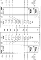
- FIG. 1 is a diagram showing a schematic configuration of a communication system 1 according to the present embodiment.
- the configuration of the communication system 1 according to the present embodiment is divided into “2.1. Basic configuration”, “2.2. Configuration on the transmission side”, and “2.3. Configuration on the reception side”. I will explain.
- the communication system 1 according to the present embodiment includes two different communication units 100A and 100B.
- the communication unit 100A and the communication unit 100B are connected by a plurality of transmission paths 20a to 20z, and transmit and receive data to and from each other through the transmission paths 20a to 20z.
- the communication units 100A and 100B according to the present embodiment may transmit and receive each of a plurality of data via different transmission paths among the transmission paths 20a to 20z by serial communication.
- the communication units 100A and 100B may be simply described as “communication unit 100”.
- Each of the transmission paths 20a to 20z is a wiring for transmitting data from one of the communication units 100A and 100B to the other.
- the transmission lines 20a to 20z can be realized by a wired cable such as a copper wire or an optical fiber, for example.
- one of the communication units 100A and 100B may operate as a transmission unit that transmits data, and the other may operate as data reception unit.
- each of the communication units 100A and 100B may operate as both a transmission unit and a reception unit.
- the configuration of the communication system 1 will be described assuming that each of the communication units 100A and 100B operates as both a transmission unit and a reception unit.
- the communication unit 100A includes a signal processing unit 120, a switch 140, a transmission unit 162, and a reception unit 164.
- the communication unit 100B includes a signal processing unit 120, a switch 140, a transmission unit 162, and a reception unit 164.
- the signal processing unit 120 and the switch 140 have different processing contents depending on whether the communication unit 100 operates as a transmission side or a reception side. Therefore, operations of the signal processing unit 120 and the switch 140 will be separately described later in “2.2. Configuration on the transmission side” and “2.3. Configuration on the reception side”.
- the transmission unit 162 of the communication unit 100A includes a plurality of transmission devices TXa to TXq.
- the receiving unit 164 of the communication unit 100B includes a plurality of receiving devices RXa to RXq.
- the transmission unit 162 of the communication unit 100A and the reception unit 164 of the communication unit 100B are connected by transmission paths 20a to 20q.
- the transmission device TXa and the reception device RXa are connected by the transmission path 20a.
- each of the transmission devices TXb to TXq and each of the reception devices RXb to RXq are connected by transmission paths 20b to 20q.
- the receiving unit 164 of the communication unit 100A includes the receiving devices RXy and RXz.
- the transmission unit 162 of the communication unit 100B includes transmission devices TXy and TXz.
- the reception unit 164 of the communication unit 100A and the transmission unit 162 of the communication unit 100B are connected by transmission paths 20y and 20z. At this time, the transmission device TXy and the reception device RXy are connected by the transmission path 20y. Similarly, the transmission device TXz and the reception device RXz are connected by the transmission path 20z.
- the transmission devices TXa to TXz may be simply described as “transmission device TX” unless they are particularly distinguished. Similarly, when the receiving devices RXa to RXz are not particularly distinguished, they may be simply described as “receiving device RX”. In addition, the transmission paths 20a to 20z may be simply referred to as “transmission path 20” unless otherwise distinguished.
- the transmitting device TX transmits data to the receiving device RX connected by the transmission path 20 via the transmission path 20. Further, the receiving device RX receives data transmitted from the transmitting device TX connected via the transmission path 20.
- the transmission device TX when an optical fiber is used for the transmission path 20, the transmission device TX includes, for example, a light source and an optical modulator that changes the intensity of light output from the light source.
- the light source can be realized by, for example, a semiconductor laser.
- the transmission device TX changes the intensity of light output from the light source by controlling the optical modulator based on an electrical signal (for example, a digital signal) indicating data to be transmitted. Convert electrical signals into optical signals. Then, the transmitting device TX transmits the optical signal to the receiving device RX via the transmission path 20.
- the receiving device RX includes, for example, a photodetector (light receiving element).
- the receiving device RX receives the optical signal transmitted from the transmitting device TX via the transmission path 20 by the photodetector, and converts the received optical signal into an electrical signal.
- the data transmitted from the transmission device TX is propagated to the reception device RX via the transmission path 20 and is received by the reception device RX.
- a medium for transmitting and receiving the data for example, an optical signal or an electric signal
- the configuration of the transmission line 20 for example, optical fiber and copper wire
- the number of transmission paths 20 can be appropriately selected according to the application field and usage of the communication system 1, but is transmitted in parallel between the communication units 100 connected to each other. It is desirable that the number is equal to or greater than the number of data (for example, the maximum number).
- the transmission path 20, and the transmission device TX and reception device RX to which the transmission path 20 is connected are connected to the communication sections so that the number of transmission paths 20 exceeds the number of data transmitted in parallel between the communication sections 100. 100 may be provided.
- a part of the plurality of transmission paths 20 can be used as a redundant line. It becomes possible. That is, even when a part of the plurality of transmission lines 20 cannot secure a sufficient transmission quality due to poor connection or the like, the communication system 1 uses a redundant line as an alternative to the part of the transmission lines 20. Thus, data can be transmitted.
- the signal processing unit 120 transmits a plurality of data to be transmitted to the transmission unit 162 for transmission of data to the communication unit 100 of another electronic device that is an external device in the transmission paths 20a to 20z. Transmission is made to the external device via any one of the channels 20 (here, the transmission channels 20a to 20q).
- data to be transmitted may be described as “transmission data”.
- the signal processing unit 120 can be realized by, for example, a control unit (for example, BPU: Basic Processing Unit) that is incorporated in the communication unit 100 and controls the operation of each component included in the communication unit 100.
- a control unit for example, BPU: Basic Processing Unit
- the processing of the signal processing unit 120 may be replaced by a control unit (for example, CPU: Central Processing Unit) of an electronic device in which the communication unit 100 is incorporated. This also applies to the case where the communication unit 100 operates as the receiving side.
- the signal processing unit 120 sets a priority between the transmission data in the transmission unit 162, and transmits transmission data with a higher priority (in other words, transmission data with a higher weight). Transmission is made to an external device via the transmission line 20 having a high transmission quality.
- the switch 140 is interposed between the signal processing unit 120 and each transmission device TX constituting the transmission unit 162.
- the switch 140 is a configuration for switching a connection relationship between a signal line for the signal processing unit 120 to output each transmission data and each transmission device TX.
- the signal processing unit 120 may include a priority order storage unit 122 for storing order information indicating the priority order, and the priority order storage unit 122 may store the order information created in advance. In this case, the signal processing unit 120 may set a priority order among a plurality of data to be transmitted based on the order information stored in the priority order storage unit 122 in advance.
- the signal processing unit 120 compares the priority set for each transmission data with the transmission quality of each transmission line 20, and transmits the transmission data with higher priority to the transmission line with higher transmission quality.
- the switch 140 is a connection between each transmission device TX and a signal line for the signal processing unit 120 to output each transmission data according to the association between each transmission data and each transmission path 20 by the signal processing unit 120. Switch relationships.
- transmission data having a higher priority among a plurality of transmission data output from each signal line of the signal processing unit 120 is transmitted to the external device via the transmission path 20 having a higher transmission quality.
- the signal processing unit 120 cannot secure a transmission quality sufficient for transmitting each transmission data among the plurality of transmission lines 20 to the transmission unit 162 (that is, the transmission quality is lower than the threshold value).
- the transmission data may be transmitted to an external device via another transmission path 20 while avoiding use.
- the example shown in FIG. 1 shows the case where the transmission quality of the transmission line 20a is the highest among the transmission lines 20a to 20q, and then the transmission quality is high in the order of the transmission lines 20p and 20q.
- the transmission paths 20b and 20c show a case where sufficient transmission quality for transmitting each transmission data cannot be secured.
- the signal processing unit 120 sets the priority order among the data as data D12> data D14> data D16.
- the signal processing unit 120 avoids the use of the transmission lines 20b and 20c, and among the transmission lines 20 other than the transmission lines 20b and 20c, the transmission line 20 with higher transmission quality has a higher priority. Associate high transmission data.
- the signal processing unit 120 associates the data D12 with the transmission path 20a. Similarly, the signal processing unit 120 associates the data D14 with the transmission line 20p, and associates the data D16 with the transmission line 20q. Then, the switch 140 connects the signal line from which the signal processing unit 120 outputs the data D12 and the transmission device TXa connected to the transmission line 20a according to the association between each transmission data and each transmission line 20. Similarly, the switch 140 connects the signal line from which the signal processing unit 120 outputs the data D14 and the transmission device TXp, and connects the signal line from which the signal processing unit 120 outputs the data D16 to the transmission device TXq. .
- transmission data having a higher priority among a plurality of transmission data output from each signal line of the signal processing unit 120 is transmitted to the external device via the transmission path 20 having a higher transmission quality.
- the signal processing unit 120 when data is transmitted to an external device, the signal processing unit 120 transmits the data via the transmission unit 162 unless otherwise specified. Further, hereinafter, the connection relationship between the signal line for the signal processing unit 120 to output each transmission data and each transmission device TX is simply referred to as “connection relationship between the signal processing unit 120 and the transmission unit 162. May be written. Further, the signal processing unit 120 when the communication unit 100 operates as a transmission side corresponds to an example of a “transmission processing unit”.
- the signal processing unit 120 receives a plurality of transmission data transmitted from an external device (that is, another communication unit 100) via a plurality of transmission paths 20 (here, transmission paths 20a to 20q). 164 is received. In the following, when receiving data transmitted from an external device, the signal processing unit 120 receives the data via the receiving unit 164 unless otherwise specified.
- a switch 140 is interposed between the signal processing unit 120 and each receiving device RX constituting the receiving unit 164.
- the switch 140 switches a connection relationship between a signal line for inputting each transmission data to the signal processing unit 120 and each receiving device RX.
- the connection relationship between the signal line for inputting each transmission data to the signal processing unit 120 and each receiving device RX is simply referred to as “the connection relationship between the signal processing unit 120 and the receiving unit 164”. May be written.
- the signal processing unit 120 when the communication unit 100 operates as a reception side corresponds to an example of a “reception processing unit”.
- the signal processing unit 120 includes a transmission quality determination unit 124.
- the transmission quality determination unit 124 determines the transmission quality of the transmission path 20 used for transmission of the transmission data based on the transmission data transmitted via each transmission path 20. Note that details of the processing related to transmission quality determination by the transmission quality determination unit 124 will be described later.
- the signal processing unit 120 determines that the transmission quality of the transmission line 20 is not suitable for transmission of transmission data based on the determination result of transmission quality, the transmission line 20 is suitable for transmission of transmission data.
- the notification unit 200 may be notified of notification information indicating that there is no notification.
- the notification unit 200 is configured to notify the user of notification information.
- the notification unit 200 can be realized by various devices provided in an electronic device in which the communication unit 100 is incorporated.
- the notification unit 200 can be realized by a device such as a display that can display image information, character information, and the like as notification information.
- the notification unit 200 can be realized by a device such as a speaker that can output audio information as notification information.
- the notification unit 200 may be realized by a light source such as an LED (Light Emitting Diode). In this case, the notification unit 200 may notify the user of notification information such as a warning by turning on or blinking.
- the notification unit 200 may be a communication device for communicating with an external device (for example, a server) via a network.
- the notification unit 200 may notify the external device of the notification information.
- the notification unit 200 may notify the management server for performing the maintenance service of the communication unit 100 as notification information, for example, a decrease in transmission quality due to poor connection.
- the management server side analyzes the notification information notified from the communication unit 100, and builds a support system that notifies the user of a coping method for improving the degradation of transmission quality based on the result of the analysis. It is also possible.
- the signal processing unit 120 and the switch 140 are processed when the communication unit 100 operates as the transmission side or the reception side, and when the communication unit 100 operates as the reception side, depending on whether the communication unit 100 operates as the transmission side or the reception side. Needless to say, these may be switched as appropriate.
- the communication unit 100 may operate as only one of the transmission side and the reception side.
- the communication unit 100 When the communication unit 100 is operated as one of the transmission side and the reception side, the communication unit 100 does not necessarily need to include the configuration on the other side.
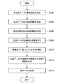
- FIG. 2 is a flowchart showing an example of a series of operations of the communication unit 100 on the transmission side according to the present embodiment, and shows a flow of a series of processes when the communication unit 100 operates as the transmission side.
- Step S102 Set order information for each transmission data
- the signal processing unit 120 weights a plurality of transmission data according to a predetermined condition.
- the signal processing unit 120 acquires rank information indicating a priority order among a plurality of pieces of data to be transmitted, and a priority order (that is, a weight) between the plurality of pieces of data based on the rank information. May be set.
- the signal processing unit 120 may include a priority order storage unit 122 for storing the order information, and the priority order storage unit 122 may store the order information created in advance. In this case, the signal processing unit 120 may set a priority order among a plurality of data to be transmitted based on the order information stored in the priority order storage unit 122 in advance.
- the signal processing unit 120 may acquire rank information from the outside, and set a priority rank among a plurality of data to be transmitted based on the acquired rank information.
- the signal processing unit 120 may set the priority order among a plurality of data based on the order information generated by the control unit (for example, CPU) of the electronic device in which the communication unit 100 is incorporated. Good. Further, the signal processing unit 120 may store the acquired order information in the priority order storage unit 122.
- the priority order among a plurality of data to be transmitted is set according to predetermined conditions such as the type of data to be transmitted, the usage of the data, the capacity of the data, and the like. Good.
- image data such as a moving image or a still image or audio data is transmitted based on a streaming method
- real-time characteristics are required for transmission of the data.
- image data and audio data have a larger capacity than text data and some control data.
- the data to be transmitted may include data that does not require real-time property, such as some control data, or data with a small capacity such as text data.
- data that does not require real-time performance even if it is necessary to retransmit the data due to the occurrence of a transmission error, it is not always necessary to immediately execute processing based on the data. Is small.
- the amount of delay associated with the resend is larger than when resending data with a large capacity such as image data or audio data. small. Therefore, the priority of data that does not require real-time properties, such as some control data and text data, and data that has a smaller capacity than other data is set to be lower than other data. Good.
- the priority setting (weighting) between the data shown above is merely an example, and is not limited to the example shown above.
- the priority order between data may differ depending on the application field of the communication system 1 according to the present embodiment and the usage of the communication system 1. Therefore, for example, according to the application field of the communication system 1 and the usage of the communication system 1, the setting of the priority order between the data may be changed as appropriate.
- Step S104 Transmit transmission data and rank information
- the signal processing unit 120 connects the order information and the plurality of transmission data to the communication unit 100 via the transmission paths 20a to 20z (that is, other communication units 100). Send to. Then, the signal processing unit 120 determines the transmission quality of each of the transmission paths 20 (here, the transmission paths 20a to 20q) used for transmitting data to the external device among the transmission paths 20a to 20z. Instruct the equipment. At this time, transmission data transmitted from the signal processing unit 120 to the external device is used by the external device for determination of transmission quality. Therefore, as the transmission data, for example, initial data for transmission quality determination may be stored in a device that can be read by the signal processing unit 120.
- the transmission quality is an index indicating communication quality when the transmission line 20 transmits data, and a specific example is an error occurrence rate of the transmission line 20.
- the transmission quality permitted when transmitting transmission data corresponding to the priority for each priority indicated by the rank information. May be notified to the external device (hereinafter referred to as “transmission quality threshold for each priority” in some cases).
- Step S106 Receive transmission quality information of each transmission path
- the signal processing unit 120 acquires transmission quality information indicating the transmission quality of each of the transmission paths 20a to 20q from the external device as a response to the instruction related to the determination of the transmission quality.
- the configuration for acquiring the transmission quality information corresponds to an example of the “order information acquisition unit” in the communication unit 100 on the transmission side.
- the signal processing unit 120 may use any of the transmission paths 20a to 20z as a transmission path for transmitting / receiving an instruction related to determination of transmission quality and transmission quality information to / from an external device.
- the signal processing unit 120 transmits and receives information to and from external devices via the transmission line 30. You may go.
- the signal processing unit 120 may instruct the external device to determine the transmission quality at every predetermined timing after the communication unit 100 is activated. In this case, the signal processing unit 120 may instruct the external device to determine transmission quality based on the initial data by transmitting the initial data to the external device. As another example, the signal processing unit 120 may instruct the external device to determine transmission quality based on actual data transmitted from the communication unit 100 to the external device.
- Step S108 Associating transmission data with a propagation path
- the signal processing unit 120 executes processing related to transmission of a plurality of transmission data (that is, actual data) to be transmitted. Specifically, the signal processing unit 120 acquires the plurality of transmission data from the outside of the communication unit 100.
- the plurality of transmission data is stored in a predetermined storage area such as DB (Database).
- DB Database
- the signal processing unit 120 acquires a plurality of transmission data to be transmitted from the storage area based on an instruction of a control unit (for example, CPU) of the electronic device in which the communication unit 100 is incorporated. .
- the signal processing unit 120 When the signal processing unit 120 acquires a plurality of transmission data, the signal processing unit 120 sets a priority order for each of the plurality of transmission data based on the order information. When the priority order is set for each transmission data, the signal processing unit 120 compares the priority order with the transmission quality information indicating the transmission quality of each of the transmission paths 20a to 20q, and sends each transmission data to the transmission paths 20a to 20q. Associate with one of
- the signal processing unit 120 associates, for example, transmission data set with a higher priority among the transmission data with the transmission path 20 having higher transmission quality among the transmission paths 20a to 20q.
- the signal processing unit 120 sequentially extracts each piece of transmission data in descending order of priority, and extracts the extracted transmission data among the transmission lines 20 that are not associated with other transmission data. Associate with high transmission path 20.
- the signal processing unit 120 may associate each of a plurality of transmission data with each transmission path 20.
- Step S110 Switch according to association
- the signal processing unit 120 When associating each piece of transmission data with each transmission line 20, the signal processing unit 120 outputs control information indicating the association to the switch 140 described later.
- the switch 140 switches the connection relationship between the signal processing unit 120 and the transmission unit 162 based on the control information acquired from the signal processing unit 120. Thereby, the signal line for the signal processing unit 120 to output each transmission data and the transmission device TX connected to the transmission path 20 associated with the transmission data are connected according to the association indicated by the control information. .
- Step S112 Send information indicating association between transmission data and propagation path
- the signal processing unit 120 transmits control information indicating the association between each transmission data and each transmission path 20 to the external device.
- the signal processing unit 120 may notify the external device of the control information via any one of the transmission paths 20a to 20q, or may notify the external apparatus via the dedicated transmission path 30. Good.
- the external device can identify whether each transmission data is transmitted via any of the transmission paths 20a to 20q based on the control information acquired from the signal processing unit 120.
- the configuration for transmitting (that is, notifying) the control information to an external device corresponds to an example of a “notification unit” in the communication unit 100 on the transmission side.
- Step S114 Transmission of actual data
- the signal processing unit 120 outputs each transmission data to the transmission unit 162 via the switch 140. Thereby, each transmission data is transmitted to an external apparatus via the transmission path 20 with which the said transmission data was linked
- the switch 140 switches the connection relationship between the signal processing unit 120 and the transmission unit 162 based on the control information indicating the association between each transmission data and each transmission path 20, switching of the switch 140 is controlled.
- the subject is not particularly limited.
- a control unit for example, BPU
- the signal processing unit 120 may control switching of the switch 140.
- the signal processing unit 120 does not necessarily need to output control information to the switch 140.
- a control unit for example, CPU
- the signal processing unit 120 may output the control information to the control unit.
- the communication unit 100 executes the above-described series of operations, for example, every time when a communication cable (that is, each transmission path 20) is inserted or removed, or every predetermined timing during communication (during transmission / reception of actual data). May be. At this time, needless to say, the receiving-side communication unit 100 described later also operates. With such a configuration, the communication unit 100 transmits transmission data by switching to another transmission line 20 other than the transmission line 20 even when, for example, the transmission quality of some transmission lines 20 deteriorates after the start of operation. By doing so, it becomes possible to maintain good transmission.
- the communication unit 100 transmits transmission data while avoiding the use of some of the transmission lines 20, among the plurality of transmission lines 20, other communication lines 20 other than the part of the transmission lines 20 are used.
- the transmission quality may be determined again and each transmission data may be associated with one of the other transmission paths 20.
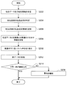
- FIG. 3 is a flowchart illustrating an example of a series of operations of the communication unit 100 on the transmission side according to the present embodiment, and illustrates a flow of a series of processes when the communication unit 100 operates as the reception side.
- Step S202 Receive transmission data and rank information
- the signal processing unit 120 transmits rank information and a plurality of transmissions transmitted from an external device via the transmission paths 20a to 20q. Data and receive. Then, the signal processing unit 120 receives an instruction related to the determination of the transmission quality of each of the transmission paths 20a to 20q from the external device.
- the signal processing unit 120 may acquire a transmission quality threshold value for each priority order from an external device.
- the signal processing unit 120 stores the acquired transmission quality threshold value for each priority order in a storage unit that can be read by itself.
- Step S204 Determine transmission quality of each transmission path
- the signal processing unit 120 sends the transmission quality determination unit 124 to each of the transmission paths 20a to 20q based on the transmission data received via each of the transmission paths 20a to 20q. Instructs transmission quality judgment.
- the transmission quality determination unit 124 determines the transmission quality of the transmission line 20 used for transmission of the transmission data based on the received transmission data.
- the transmission quality determination unit 124 measures the error rate of transmission data transmitted through each transmission line 20 and uses the error rate for transmission of the transmission data. It is good also as an index. In this case, for example, the signal processing unit 120 may recognize that the transmission quality is higher as the error rate is lower, and the transmission quality is lower as the error rate is higher.
- a specific example of the method for measuring the error rate is a measurement method based on parity bits. Specifically, by setting a parity bit for error detection in the transmission data, the actual data is based on a comparison between the bit other than the parity bit (that is, a bit indicating the actual data) and the parity bit. It is possible to determine whether or not an error is included in the bit indicating.
- the error rate measurement method based on the parity bit is merely an example, and the method is not limited as long as the transmission quality determination unit 124 can measure the error rate of the transmission data based on the received transmission data.
- Step S206 Transmit transmission quality information of each transmission path
- the signal processing unit 120 transmits transmission quality information indicating the determination result to the external device that instructed the determination of the transmission quality.
- the configuration for transmitting (that is, notifying) the transmission quality information to an external device corresponds to an example of a “notification unit” in the communication unit 100 on the receiving side.
- the signal processing unit 120 may use any of the transmission paths 20a to 20z as a propagation path for transmitting / receiving an instruction related to determination of transmission quality and transmission quality information to / from an external device. As another example, the signal processing unit 120 may transmit / receive information to / from an external device via a dedicated transmission path 30 provided separately from the transmission paths 20a to 20z.
- Step S208 Receive information indicating association between transmission data and propagation path
- the signal processing unit 120 receives control information indicating an association between each transmission data and each transmission path 20 from an external device.
- Step S210 Switch is switched according to association
- the signal processing unit 120 When receiving control information from the external device, the signal processing unit 120 outputs the control information to the switch 140.
- the switch 140 switches the connection relationship between the signal processing unit 120 and the receiving unit 164 based on the control information acquired from the signal processing unit 120.
- the signal line for inputting each transmission data to the signal processing unit 120 and the receiving device RX connected to the transmission path 20 associated with the transmission data are connected according to the association indicated by the control information. .
- Step S212 Reception of actual data
- the signal processing unit 120 acquires transmission data (that is, actual data) transmitted via each transmission path 20 from the reception unit 164 via the switch 140.
- the signal processing unit 120 can identify and receive each transmission data transmitted via each transmission path 20 and associated with the transmission path 20.
- Step S214 Error rate is within threshold
- the signal processing unit 120 acquires the transmission quality threshold value for each priority
- the transmission quality determination result based on the transmission data transmitted via each transmission path 20 and the threshold value are obtained. By comparing, it may be determined whether each transmission line 20 is suitable for transmission of transmission data.
- the signal processing unit 120 may use the transmission quality determination result based on the initial data for comparison with the transmission quality threshold value for each priority.
- the signal processing unit 120 compares the transmission quality determination result based on the actual data with the transmission quality threshold value for each priority order, so that each transmission line 20 has the transmission data. It may be determined whether it is suitable for transmission.
- the signal processing unit 120 describes that the transmission quality of each transmission line 20 is a threshold value corresponding to the priority order of transmission data transmitted via the transmission line 20 (hereinafter referred to as “threshold value corresponding to transmission data”). May be determined to be not suitable for transmission of transmission data. Specifically, when the signal processing unit 120 has an error rate of transmission data transmitted through each transmission path 20 exceeding a threshold corresponding to the priority of transmission data transmitted through the transmission path 20 May determine that the transmission line 20 is not suitable for transmission of transmission data.
- Step S216 Notify warning
- the signal processing unit 120 indicates that the transmission path 20 is not suitable for transmission of transmission data.
- Notification information indicating that the notification unit 200 may be notified.
- the signal processing unit 120 notifies the user that a contact failure has occurred between the communication unit 100 and each transmission path 20 by the notification information, and notifies the user of the communication unit 100 and each transmission path. 20 may be prompted to clean the connecting end surface.
- the signal processing unit 120 may notify the notification unit 200 when the number of transmission lines 20 whose transmission quality falls below a threshold corresponding to transmission data among a plurality of transmission lines 20 exceeds a predetermined number.
- the notification information may be notified.
- the signal processing unit 120 calculates the transmission rate of each transmission path 20, and uses the calculated transmission rate as a transmission rate required for transmission of transmission data transmitted through the transmission path 20 (hereinafter “transmission data”). It may be determined whether or not the transmission line 20 is suitable for transmission of transmission data. In this case, when the transmission rate of the transmission line 20 is lower than the transmission rate corresponding to the transmission data, the signal processing unit 120 determines that the transmission line 20 is not suitable for transmission of transmission data, and the notification unit 200 may notify the notification information.
- the transmission rate corresponding to the transmission data is set for each priority of the transmission data, for example, similarly to the threshold value corresponding to the transmission data, and is notified from the communication unit 100 on the transmission side to the communication unit 100 on the reception side. Good.
- the unit 120 may mainly execute processing related to determination of transmission quality.
- the signal processing unit 120 on the receiving side receives transmission data for transmission quality determination or actual data that can be used for transmission quality determination. May be instructed, and the result may be notified to an external device (ie, the communication unit 100 on the transmission side).
- the transmission quality determination unit 124 may determine the transmission quality based on the output of a signal propagated through the transmission path 20 (for example, in the case of optical communication, the intensity of light (light quantity)). In this case, for example, the transmission quality determination unit 124 has a higher transmission quality as the transmission path 20 has a higher signal output. When the output of the signal falls below a threshold value, the corresponding transmission path 20 propagates information. Therefore, it may be determined that sufficient transmission quality is not ensured.
- the switch 140 causes the signal processing unit 120 to input and output transmission data, and the transmission device TX and the reception unit 164 constituting the transmission unit 162.
- the connection relationship between each receiving device RX to be configured is switched. Therefore, in the communication system 1 according to the present embodiment, if the transmission device TX and the reception device RX are paired and connected via the transmission line 20, the physical pins to which each transmission line 20 is connected (in other words, the transmission device).
- the physical arrangement of the signal lines (TX and the signal lines connected to the receiving device RX) is not limited.
- the communication system 1 connects each communication unit 100 and the communication cable when connecting the communication cable (that is, each transmission path 20) to each communication unit 100. It is possible to relax restrictions on the orientation of the connector for connecting between the two.
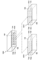
- FIG. 4 is a diagram for describing a modification of the communication system 1 according to the present embodiment, and schematically illustrates an example of a connector that connects between the communication unit 100 and a communication cable (each transmission path 20). It is the figure shown in.
- reference numeral 160A schematically shows a connector on the communication unit 100A side for connecting a communication cable to the communication unit 100A in FIG.
- Reference numerals TX2 and TX4 schematically indicate physical pins connected to each transmission device TX of the communication unit 100A.
- reference numerals RX6 and RX8 schematically indicate physical pins connected to the receiving devices RX of the communication unit 100A.
- Reference numerals 160B and 160C indicate connectors on the communication cable side.
- Reference numerals RX2 and RX4 schematically indicate physical pins for connecting the transmission path 20 connected to each receiving device RX of the communication unit 100B in FIG. 1 to the communication unit 100A.
- reference numerals TX2 and TX4 schematically indicate physical pins for connecting the transmission path 20 connected to each transmission device TX of the communication unit 100B to the communication unit 100A.
- Reference numeral 166 indicates one surface of the connectors 160A to 160C (herein, “upper surface”), and reference numeral 168 indicates a surface opposite to the one surface (here, “ The lower surface ”).
- the connector 160B is a connector for both the communication unit 100A and the communication cable such that the upper surface 166 of the connector on the communication unit 100A side and the upper surface 166 of the connector on the communication cable side face the same direction. Shows an example in which is connected.
- the connector 160B is used when the connectors of both the communication unit 100A and the communication cable are connected such that the upper surface 166 of the connector on the communication unit 100A side and the lower surface 168 of the connector on the communication cable side face the same direction. An example is shown.
- the physical pin TX2 and the physical pin RX2 are connected.
- the physical pin TX4 and the physical pin RX4 are connected.
- the physical pin RX6 and the physical pin TX6, and the physical pin RX8 and the physical pin TX8 are respectively connected.
- the physical pin TX2 and the physical pin RX4 are connected.
- the physical pin TX4 and the physical pin RX2, the physical pin RX6 and the physical pin TX8, and the physical pin RX8 and the physical pin TX6 are respectively connected.
- the communication system 1 connects the signal processing units 120 of both the communication units 100A and 100B by switching the switch 140. It is possible to keep the relationship always constant.
- the data D12 transmitted from the signal processing unit 120 of the communication unit 100A is received by the signal processing unit 120 of the communication unit 100B.
- the communication unit 100A controls the switch 140 so that the data D12 is always transmitted from the transmission device TX connected to the physical pin TX2.
- the data D12 transmitted from the communication unit 100A is transferred to the 100B via the transmission line 20 (here, the transmission line 20a) connected to the physical pin RX2. Is transmitted. Therefore, the communication unit 100B controls the switch 140 so that the signal line for inputting the data D12 to the signal processing unit 120 and the receiving device RX connected to the transmission path 20a are connected.
- the data D12 transmitted from the communication unit 100A is the transmission path 20 connected to the physical pin RX4 (here, the transmission path 20b).
- the communication unit 100B controls the switch 140 so that the signal line for inputting the data D12 to the signal processing unit 120 and the receiving device RX connected to the transmission path 20b are connected.
- the connection between the signal processing units 120 of both the communication units 100A and 100B can be achieved even in a configuration in which the orientation of the connector (for example, up and down) can be connected in a reversible manner. It is possible to keep the relationship constant at all times. Therefore, in the communication system 1 according to the present embodiment, if the transmission device TX and the reception device RX are paired and connected via the transmission line 20, the physical pins to which each transmission line 20 is connected (in other words, the transmission device).
- the physical arrangement of the signal lines (TX and the signal lines connected to the receiving device RX) is not limited.
- both the communication units 100A and 100B include both the transmission unit 162 and the reception unit 164 .
- either one includes only the transmission unit 162 and the other receives.
- the same applies to a configuration including only the portion 164.
- the series of operations described above can be configured by a program for causing a control unit (for example, BPU) for controlling the operation of each component included in the communication unit 100 to function.
- a control unit for example, BPU
- the position of the program is not limited as long as it can be read by an apparatus including the configuration for executing the above-described processing.
- the program may be stored in a recording medium connected from the outside of the apparatus. In this case, it is preferable to configure the control unit of the communication unit 100 to execute the program by connecting a recording medium storing the program to the apparatus.
- the communication system 1 sets priorities among a plurality of transmission data in advance. Further, the communication system 1 determines the transmission quality of the plurality of transmission paths 20 that connect the electronic devices. Then, the communication system 1 performs control so that transmission data with a higher priority is transmitted via the transmission path 20 with higher transmission quality. With such a configuration, the communication system 1 according to the present embodiment includes other transmission lines 20 that can ensure transmission quality even when some transmission lines 20 cannot secure sufficient transmission quality due to poor connection or the like. The data can be transmitted through the network. At this time, the communication system 1 gives priority to the data having a higher weight and transmits the data via a transmission path having a higher transmission quality. Therefore, the data having a higher weight suppresses the frequency of retransmission and more reliably transmits the data. It becomes possible.
- the communication system 1 according to the present embodiment it is possible to realize good data transmission even in a situation where connection failure may occur in some transmission paths. Therefore, according to the communication system 1 according to the present embodiment, even when high-frequency communication, which has a large influence on communication quality due to poor connection, is applied to consumer equipment such that a general user performs connection work, it is favorable. Data transmission can be realized.
- the transmission path 20 and the transmission path 20 are connected so that the number of transmission paths 20 exceeds the number of transmission data transmitted in parallel between the communication units 100.
- a transmission device TX and a reception device RX may be provided in each communication unit 100.
- a part of the plurality of transmission paths 20 can be used as a redundant line. It becomes possible. That is, the communication system 1 uses a redundant line as an alternative to some of the transmission lines 20 even when some of the transmission lines 20 cannot secure sufficient transmission quality due to poor connection or the like. Thus, transmission data can be transmitted.
- the communication system 1 performs processing related to determination of each transmission quality and association between transmission data based on the determination result and the transmission path 20, for example, insertion / removal of a communication cable (that is, each transmission path 20). It may be executed at every timing or every predetermined timing during communication.
- the communication unit 100 transmits transmission data by switching to another transmission line 20 other than the transmission line 20 even when, for example, the transmission quality of some transmission lines 20 deteriorates after the start of operation. By doing so, it becomes possible to maintain good transmission.
- the communication system 1 determines that the transmission quality of each transmission line 20 is not suitable for transmission of transmission data based on the transmission quality information
- the communication system 1 causes the notification unit 200 to notify the notification information. That is, when the communication system 1 has an abnormality in the transmission line 20 such as a connection failure, the communication system 1 notifies the user of, for example, a warning indicating the occurrence of the abnormality and a coping method for solving the abnormality as notification information. It becomes possible to do.
- the receiving-side communication unit 100 performs signal processing based on control information indicating the association between each transmission data notified from the transmitting-side communication unit 100 and each transmission path 20.
- the connection relationship between the unit 120 and the transmission unit 164 is switched.
- the communication system 1 avoids the use of a part of the transmission line 20 due to the deterioration of the transmission quality, and receives the communication unit 100 and the reception side even when the other transmission line 20 is used. It becomes possible to maintain the connection relationship with the communication unit 100 on the side. Therefore, the communication unit 100 according to the present embodiment can be incorporated in the electronic device without changing the interface (connection relationship) between the electronic device to which the communication unit 100 is connected and the communication unit 100. Become.
- a transmission processing unit that associates each of the plurality of data with any one of the plurality of transmission lines, and causes the transmission unit to transmit the data to an external device via the transmission line;
- a transmission quality information acquisition unit for acquiring transmission quality information indicating the transmission quality of each of the plurality of transmission paths;
- a switch for switching the connection relationship between the transmission processing unit and the plurality of transmission paths based on rank information indicating weights between the plurality of data and the acquired transmission quality information;
- a transmission device comprising: (2) The transmission device according to (1), wherein the switch switches the connection relationship so that the data having a large weight is transmitted via the transmission path having the high transmission quality.
- the switch according to (5) or (6) wherein when the transmission quality of the part of the transmission lines is below a threshold, the switch switches the connection relation based on transmission quality information of each of the other transmission lines. Transmitter.
- a reception processing unit that receives a plurality of data from an external device via a plurality of transmission paths; For each of the plurality of transmission paths, based on the data received via the transmission path, a transmission quality determination unit that determines the transmission quality of the transmission path; In order for the external device to associate the plurality of data with the plurality of transmission lines, a notification unit that notifies the external device of the determination result of the transmission quality of each of the plurality of transmission lines, A receiving device.
- a control information acquisition unit for acquiring control information indicating association between the plurality of data and the plurality of transmission paths from the external device; Based on the acquired control information, a switch for switching a connection relationship between the reception processing unit and the plurality of transmission lines,
- the transmission quality determination unit measures an error rate of the data received via the transmission path for each of the plurality of transmission paths, and determines the transmission quality based on a result of the measurement, (11) or The receiving device according to (12).
- the receiving device according to any one of 13).
- the said notification part is a receiver as described in said (14) which alert
Abstract
Description
1.通信システムの概要
2.通信システムの構成
2.1.基本構成
2.2.送信側の構成
2.3.受信側の構成
3.通信システムの動作
3.1.送信側の動作
3.2.受信側の動作
3.通信システムの変形例
4.まとめ The description will be made in the following order.
1. 1. Overview of communication system Configuration of communication system 2.1. Basic configuration 2.2. Configuration on transmitting side 2.3. 2. Configuration on the receiving side Operation of communication system 3.1. Operation on transmission side 3.2. 2. Operation on the receiving side 3. Modification of communication system Summary
まず、本開示の実施形態に係る通信システム1の課題を整理したうえで、当該通信システム1の概要について説明する。本実施形態に係る通信システム1は、互いに異なる複数の電子機器間を複数の伝送路で接続し、当該複数の伝送路を介して複数のデータを送受信する。通信システム1では、伝送路として、銅線または光ファイバーなどの有線ケーブルを用いる。 <1. Overview of communication system>
First, after arranging the problems of the
図1を参照して、本実施形態に係る通信システム1の概略的な構成について説明する。図1は、本実施形態に係る通信システム1の概略的な構成を示した図である。なお、以降では、本実施形態に係る通信システム1の構成について、「2.1.基本構成」、「2.2.送信側の構成」、及び「2.3.受信側の構成」に分けて説明する。 <2. Configuration of communication system>
A schematic configuration of a
まず、本実施形態に係る通信システム1の基本構成について説明する。図1に示すように、本実施形態に係る通信システム1は、異なる2つの通信部100A及び100Bを含む。 [2.1. Basic configuration]
First, the basic configuration of the
次に、通信部100が送信側として動作する場合ついて、当該通信部100に含まれる構成のうち、特に、信号処理部120及びスイッチ140の動作に着目して説明する。 [2.2. Sender configuration]
Next, the case where the communication unit 100 operates as a transmission side will be described by focusing on the operations of the
次に、通信部100が受信側として動作する場合について、当該通信部100に含まれる構成のうち、特に、信号処理部120及びスイッチ140の動作に着目して説明する。 [2.3. Receiver configuration]
Next, the case where the communication unit 100 operates as a reception side will be described by focusing on the operation of the
次に、図2及び図3を参照しながら、通信部100の一連の処理の流れについて、当該通信部100が送信側として動作する場合と、受信側として動作する場合とに分けて説明する。 <3. Operation of communication system>
Next, a series of processing flows of the communication unit 100 will be described with reference to FIGS. 2 and 3 separately for a case where the communication unit 100 operates as a transmission side and a case where the communication unit 100 operates as a reception side.
まず、図2を参照して、通信部100が送信側として動作する場合について説明する。図2は、本実施形態に係る送信側の通信部100の一連の動作の一例を示したフローチャートであり、通信部100が送信側として動作する場合における一連の処理の流れを示している。 [3.1. Operation on the sending side]
First, a case where the communication unit 100 operates as a transmission side will be described with reference to FIG. FIG. 2 is a flowchart showing an example of a series of operations of the communication unit 100 on the transmission side according to the present embodiment, and shows a flow of a series of processes when the communication unit 100 operates as the transmission side.
信号処理部120は、複数の伝送データをあらかじめ決められた条件に従い重み付けする。具体的な一例として、信号処理部120は、送信対象となる複数のデータ間において優先順位を示す順位情報を取得し、当該順位情報に基づき複数の複数のデータ間の優先順位(即ち、重み)を設定してもよい。 (Step S102: Set order information for each transmission data)
The
優先順位の設定を行うと、信号処理部120は、順位情報と複数の伝送データとを、通信部100に伝送路20a~20zを介して接続された外部機器(即ち、他の通信部100)へ送信する。そして、信号処理部120は、伝送路20a~20zのうち外部機器へのデータの送信に用いられる伝送路20(ここでは、伝送路20a~20qとする)それぞれの伝送品位の判定を、当該外部機器に指示する。なお、このとき、信号処理部120が外部機器に送信する伝送データは、当該外部機器により伝送品位の判定に使用される。そのため、当該伝送データとして、例えば、伝送品位判定用の初期データを、信号処理部120が読み出し可能なデバイスに記憶させておいてもよい。なお、伝送品位とは、伝送路20がデータを伝送する際の通信品質を示す指標であり、具体的な一例として、伝送路20のエラー発生率が挙げられる。 (Step S104: Transmit transmission data and rank information)
When the priority order is set, the
信号処理部120は、伝送品位の判定に係る指示の応答として、外部機器から伝送路20a~20qそれぞれの伝送品位を示す伝送品位情報を取得する。なお、信号処理部120のうち、伝送品位情報を取得する構成が、送信側の通信部100における「順位情報取得部」の一例に相当する。 (Step S106: Receive transmission quality information of each transmission path)
The
伝送品位情報を取得すると、信号処理部120は、送信対象となる複数の伝送データ(即ち、実データ)の送信に係る処理を実行する。具体的には、信号処理部120は、当該複数の伝送データを通信部100の外部から取得する。なお、複数の伝送データは、例えば、DB(Database)のような所定の記憶領域に記憶されている。この場合には、信号処理部120は、例えば、通信部100が組み込まれた電子機器の制御ユニット(例えば、CPU)の指示に基づき、当該記憶領域から送信対象となる複数の伝送データを取得する。 (Step S108: Associating transmission data with a propagation path)
When the transmission quality information is acquired, the
信号処理部120は、各伝送データと各伝送路20とを関連付けると、当該関連付けを示す制御情報を後述するスイッチ140に出力する。スイッチ140は、信号処理部120から取得した制御情報に基づき、信号処理部120と送信部162との間の接続関係を切り替える。これにより、信号処理部120が各伝送データを出力するための信号線と、当該伝送データに関連付けられた伝送路20に接続された送信デバイスTXとが、当該制御情報が示す関連付けに従って接続される。 (Step S110: Switch according to association)
When associating each piece of transmission data with each transmission line 20, the
また、信号処理部120は、各伝送データと各伝送路20とを関連付けを示す制御情報を、外部機器に送信する。このとき、信号処理部120は、当該制御情報を、伝送路20a~20qのいずれかを介して外部機器に通知してもよいし、専用の伝送路30を介して外部機器に通知してもよい。これにより、外部機器は、信号処理部120から取得した制御情報に基づき、各伝送データが、伝送路20a~20qのいずれかを介して送信されるかを識別することが可能となる。なお、信号処理部120のうち、当該制御情報を外部機器に送信する(即ち、通知する)構成が、送信側の通信部100における「通知部」の一例に相当する。 (Step S112: Send information indicating association between transmission data and propagation path)
In addition, the
制御情報を外部機器に送信すると、信号処理部120は、各伝送データを、スイッチ140を介して送信部162に出力する。これにより、各伝送データは、当該伝送データが関連付けられた伝送路20を介して外部機器に送信される。 (Step S114: Transmission of actual data)
When the control information is transmitted to the external device, the
次に、図3を参照して、通信部100が受信側として動作する場合について説明する。図3は、本実施形態に係る送信側の通信部100の一連の動作の一例を示したフローチャートであり、通信部100が受信側として動作する場合における一連の処理の流れを示している。 [3.2. Operation on the receiving side]
Next, a case where the communication unit 100 operates as a receiving side will be described with reference to FIG. FIG. 3 is a flowchart illustrating an example of a series of operations of the communication unit 100 on the transmission side according to the present embodiment, and illustrates a flow of a series of processes when the communication unit 100 operates as the reception side.
通信部100が起動すると(もしくは、通信部100に各伝送路20が接続されると)、信号処理部120は、伝送路20a~20qを介して外部機器から送信された順位情報と複数の伝送データとを受信する。そして、信号処理部120は、外部機器から、伝送路20a~20qそれぞれの伝送品位の判定に係る指示を受ける。 (Step S202: Receive transmission data and rank information)
When the communication unit 100 is activated (or when each transmission path 20 is connected to the communication unit 100), the
伝送品位の判定に係る指示を受けると、信号処理部120は、伝送品位判定部124に、伝送路20a~20qのそれぞれを介して受信した各伝送データに基づく、当該伝送路20a~20qそれぞれの伝送品位の判定を指示する。当該指示を受けて、伝送品位判定部124は、受信した各伝送データに基づき、当該伝送データの伝送に用いた伝送路20の伝送品位を判定する。具体的な一例として、伝送品位判定部124は、各伝送路20を介して伝送された伝送データのエラー率を測定し、当該エラー率を当該伝送データの伝送に用いた伝送路20の伝送品位の指標としてもよい。この場合には、信号処理部120は、例えば、エラー率が低いほど伝送品位が高く、エラー率が高いほど伝送品位が低いと認識してもよい。 (Step S204: Determine transmission quality of each transmission path)
When receiving the instruction relating to the determination of the transmission quality, the
信号処理部120は、伝送品位判定部124による伝送路20a~20qそれぞれの伝送品位の判定結果に基づき、当該判定結果を示す伝送品位情報を、当該伝送品位の判定を指示した外部機器に送信する。なお、信号処理部120のうち、当該伝送品位情報を外部機器に送信する(即ち、通知する)構成が、受信側の通信部100における「通知部」の一例に相当する。 (Step S206: Transmit transmission quality information of each transmission path)
Based on the transmission quality determination result of each of the
また、信号処理部120は、外部機器から、各伝送データと各伝送路20との関連付けを示す制御情報を受信する。 (Step S208: Receive information indicating association between transmission data and propagation path)
Further, the
外部機器から制御情報を受信すると、信号処理部120は、当該制御情報をスイッチ140に出力する。スイッチ140は、信号処理部120から取得した制御情報に基づき、信号処理部120と受信部164との間の接続関係を切り替える。これにより、信号処理部120に各伝送データを入力するための信号線と、当該伝送データに関連付けられた伝送路20に接続された受信デバイスRXとが、当該制御情報が示す関連付けに従って接続される。 (Step S210: Switch is switched according to association)
When receiving control information from the external device, the
制御情報に基づきスイッチ140が切り替えられると、信号処理部120は、各伝送路20を介して伝送された伝送データ(即ち、実データ)を、スイッチ140を介して受信部164から取得する。これにより、信号処理部120は、各伝送路20を介して伝送された、当該伝送路20に関連付けられた伝送データそれぞれを識別して受信することが可能となる。 (Step S212: Reception of actual data)
When the
なお、信号処理部120は、優先順位ごとの伝送品位の閾値を取得している場合には、各伝送路20を介して伝送された伝送データに基づく伝送品位の判定結果と、当該閾値とを比較することで、各伝送路20が伝送データの伝送に適しているかを判定してもよい。また、信号処理部120は、優先順位ごとの伝送品位の閾値との比較に、初期データに基づく伝送品位の判定結果を使用してもよい。また、実データの伝送開始後であれば信号処理部120は、当該実データに基づく伝送品位の判定結果を優先順位ごとの伝送品位の閾値と比較することで、各伝送路20が伝送データの伝送に適しているかを判定してもよい。 (Step S214: Error rate is within threshold)
In addition, when the
少なくとも一部の伝送路20が伝送データの伝送に適していないと判定された場合には(ステップS214、NO)、信号処理部120は、当該伝送路20が伝送データの伝送に適していない旨を示す報知情報を、報知部200に報知させてもよい。なお、信号処理部120は、当該報知情報により、通信部100と各伝送路20との間で接触不良が発生している旨をユーザに通知し、当該ユーザに、通信部100と各伝送路20との間の接続端面のクリーニングを促してもよい。 (Step S216: Notify warning)
When it is determined that at least a part of the transmission path 20 is not suitable for transmission of transmission data (step S214, NO), the
ここで、本実施形態に係る通信システム1の変形例について説明する。上記に示すように、本実施形態に係る通信システム1は、スイッチ140により、信号処理部120が伝送データを入出力する信号線と、送信部162を構成する各送信デバイスTX及び受信部164を構成する各受信デバイスRXとの間の接続関係を切り替える。そのため、本実施形態に係る通信システム1では、送信デバイスTXと受信デバイスRXとが対となり伝送路20を介して接続されれば、各伝送路20が接続される物理ピン(換言すると、送信デバイスTX及び受信デバイスRXのそれぞれに接続された信号線)の物理的な配置は限定されない。 <4. Modified example of communication system>
Here, a modification of the
以上説明したように、本実施形態に係る通信システム1は、複数の伝送データ間にあらかじめ優先順位を設定する。また、通信システム1は、電子機器間を接続する複数の伝送路20の伝送品位を判定する。そして、通信システム1は、優先順位の高い伝送データほど、より伝送品位の高い伝送路20を介して送信されるように制御する。このような構成により、本実施形態に係る通信システム1は、一部の伝送路20が接続不良等により十分な伝送品位を確保できない場合においても、伝送品位を確保可能な他の伝送路20を介してデータを送信することが可能となる。また、このとき通信システム1は、重みの大きいデータを優先して、より伝送品位の高い伝送路を介して送信するため、重みの大きいデータほど再送が発生する頻度を抑え、より確実に伝送することが可能となる。 <5. Summary>
As described above, the
(1)
複数のデータのそれぞれを、複数の伝送路のうちのいずれかの伝送路に関連付けて、送信部に、当該伝送路を介して当該データを外部機器へ送信させる送信処理部と、
前記複数の伝送路それぞれの伝送品位を示す伝送品位情報を取得する伝送品位情報取得部と、
前記複数のデータ間の重みを示す順位情報と、取得した前記伝送品位情報とに基づき、前記送信処理部と前記複数の伝送路との間の接続関係を切り替えるスイッチと、
を備えた、送信装置。
(2)
前記スイッチは、前記重みの大きいデータが前記伝送品位の高い伝送路を介して送信されるように前記接続関係を切り替える、前記(1)に記載の送信装置。
(3)
前記複数のデータのうち前記重みのより大きいデータが、前記複数の伝送路のうち前記伝送品位がより高い伝送路に関連付けられる、前記(2)に記載の送信装置。
(4)
前記重みは、前記複数のデータの優先順位を示す順位情報である、前記(1)~(3)のいずれか一項に記載の送信装置。
(5)
前記スイッチは、複数の伝送路のうち少なくとも一部の伝送路の前記伝送品位が閾値を下回る場合に、当該一部の伝送路以外の他の伝送路を介して前記複数のデータが送信されるように、前記接続関係を切り替える、前記(1)~(4)のいずれか一項に記載の送信装置。
(6)
前記複数の伝送路の数は、前記複数のデータの数よりも多い、前記(5)に記載の送信装置。
(7)
前記スイッチは、前記一部の伝送路の前記伝送品位が閾値を下回る場合に、前記他の伝送路それぞれの伝送品位情報に基づき、前記接続関係を切り替える、前記(5)または(6)に記載の送信装置。
(8)
前記複数のデータと前記複数の伝送路との間の関連付けを示す制御情報を、前記外部機器に通知する通知部を備えた、前記(1)~(6)のいずれか一項に記載の送信装置。
(9)
前記順位情報を取得する順位情報取得部を備え、
取得された当該順位情報に基づき、前記複数のデータと前記複数の伝送路とが関連付けられる、前記(1)~(8)のいずれか一項に記載の送信装置。
(10)
前記順位情報を記憶する記憶部を備え、
前記記憶部に記憶された当該順位情報に基づき、前記複数のデータと前記複数の伝送路とが関連付けられる、前記(1)~(9)のいずれか一項に記載の送信装置。
(11)
複数の伝送路を介して外部機器から複数のデータを受信する受信処理部と、
前記複数の伝送路それぞれについて、当該伝送路を介して受信した前記データを基に、当該伝送路の伝送品位を判定する伝送品位判定部と、
前記外部機器が、前記複数のデータと前記複数の伝送路とを関連付けるために、当該複数の伝送路それぞれの前記伝送品位の判定結果を当該外部機器に通知する通知部と、
を備えた、受信装置。
(12)
前記複数のデータと前記複数の伝送路との間の関連付けを示す制御情報を、前記外部機器から取得する制御情報取得部と、
取得した前記制御情報に基づき、前記受信処理部と前記複数の伝送路との間の接続関係を切り替えるスイッチと、
を備えた、前記(11)に記載の受信装置。
(13)
前記伝送品位判定部は、前記複数の伝送路それぞれについて、当該伝送路を介して受信した前記データのエラー率を測定し、当該測定の結果に基づき前記伝送品位を判定する、前記(11)または(12)に記載の受信装置。
(14)
前記複数の伝送路うち少なくとも一部の前記伝送品位が、前記複数のデータを送信するために要する前記伝送品位を下回る場合に、報知情報を報知する報知部を備えた、前記(11)~(13)のいずれか一項に記載の受信装置。
(15)
前記報知部は、前記複数の伝送路のうち、前記伝送品位が閾値を下回る伝送路の数が所定数を超えた場合に、前記報知情報を報知する、前記(14)に記載の受信装置。
(16)
前記複数の伝送路うち少なくとも一部の伝送レートが、前記複数のデータを送信するために要する伝送レートを下回る場合に、報知情報を報知する報知部を備えた、前記(11)~(13)のいずれか一項に記載の受信装置。
(17)
プロセッサに、複数のデータのそれぞれを、複数の伝送路のうちのいずれかの伝送路に関連付けさせて、送信部に、当該伝送路を介して当該データを外部機器へ送信させることと、
前記複数の伝送路それぞれの伝送品位を示す伝送品位情報を取得することと、
スイッチに、前記複数のデータ間の重みを示す順位情報と、取得した前記伝送品位情報とに基づき、前記プロセッサと前記複数の伝送路との間の接続関係を切り替えさせることと、
を含む、送信方法。
(18)
複数の伝送路を介して外部機器から複数のデータを受信することと、
プロセッサに、前記複数の伝送路それぞれについて、当該伝送路を介して受信した前記データを基に、当該伝送路の伝送品位を判定させることと、
前記外部機器が、前記複数のデータと前記複数の伝送路とを関連付けるために、当該複数の伝送路それぞれの前記伝送品位の判定結果を当該外部機器に通知することと、
を含む、受信方法。 The following configurations also belong to the technical scope of the present disclosure.
(1)
A transmission processing unit that associates each of the plurality of data with any one of the plurality of transmission lines, and causes the transmission unit to transmit the data to an external device via the transmission line;
A transmission quality information acquisition unit for acquiring transmission quality information indicating the transmission quality of each of the plurality of transmission paths;
A switch for switching the connection relationship between the transmission processing unit and the plurality of transmission paths based on rank information indicating weights between the plurality of data and the acquired transmission quality information;
A transmission device comprising:
(2)
The transmission device according to (1), wherein the switch switches the connection relationship so that the data having a large weight is transmitted via the transmission path having the high transmission quality.
(3)
The transmission apparatus according to (2), wherein data having a higher weight among the plurality of data is associated with a transmission path having a higher transmission quality among the plurality of transmission paths.
(4)
The transmission device according to any one of (1) to (3), wherein the weight is rank information indicating a priority of the plurality of data.
(5)
The switch transmits the plurality of data via a transmission line other than the part of the transmission lines when the transmission quality of at least a part of the transmission lines is below a threshold value. As described above, the transmission apparatus according to any one of (1) to (4), wherein the connection relation is switched.
(6)
The transmission device according to (5), wherein the number of the plurality of transmission paths is greater than the number of the plurality of data.
(7)
The switch according to (5) or (6), wherein when the transmission quality of the part of the transmission lines is below a threshold, the switch switches the connection relation based on transmission quality information of each of the other transmission lines. Transmitter.
(8)
The transmission according to any one of (1) to (6), further including a notification unit that notifies the external device of control information indicating association between the plurality of data and the plurality of transmission paths. apparatus.
(9)
A rank information acquisition unit for acquiring the rank information;
The transmission device according to any one of (1) to (8), wherein the plurality of data and the plurality of transmission paths are associated with each other based on the obtained ranking information.
(10)
A storage unit for storing the rank information;
The transmission device according to any one of (1) to (9), wherein the plurality of data and the plurality of transmission paths are associated with each other based on the order information stored in the storage unit.
(11)
A reception processing unit that receives a plurality of data from an external device via a plurality of transmission paths;
For each of the plurality of transmission paths, based on the data received via the transmission path, a transmission quality determination unit that determines the transmission quality of the transmission path;
In order for the external device to associate the plurality of data with the plurality of transmission lines, a notification unit that notifies the external device of the determination result of the transmission quality of each of the plurality of transmission lines,
A receiving device.
(12)
A control information acquisition unit for acquiring control information indicating association between the plurality of data and the plurality of transmission paths from the external device;
Based on the acquired control information, a switch for switching a connection relationship between the reception processing unit and the plurality of transmission lines,
The receiving device according to (11), comprising:
(13)
The transmission quality determination unit measures an error rate of the data received via the transmission path for each of the plurality of transmission paths, and determines the transmission quality based on a result of the measurement, (11) or The receiving device according to (12).
(14)
(11) to (11) including a notifying unit for notifying information when at least a part of the transmission quality of the plurality of transmission paths is lower than the transmission quality required for transmitting the plurality of data. The receiving device according to any one of 13).
(15)
The said notification part is a receiver as described in said (14) which alert | reports the said alerting | reporting information, when the number of the transmission paths in which the said transmission quality falls below a threshold value exceeds a predetermined number among these transmission lines.
(16)
(11) to (13) including a notification unit that notifies notification information when a transmission rate of at least a part of the plurality of transmission paths is lower than a transmission rate required for transmitting the plurality of data. The receiving device according to any one of the above.
(17)
Causing the processor to associate each of the plurality of data with any one of the plurality of transmission paths, and causing the transmission unit to transmit the data to an external device via the transmission path;
Obtaining transmission quality information indicating transmission quality of each of the plurality of transmission paths;
Causing the switch to switch the connection relationship between the processor and the plurality of transmission paths based on rank information indicating weights between the plurality of data and the acquired transmission quality information;
Including transmission method.
(18)
Receiving a plurality of data from an external device via a plurality of transmission paths;
Causing the processor to determine the transmission quality of the transmission path based on the data received via the transmission path for each of the plurality of transmission paths;
The external device notifying the external device of the determination result of the transmission quality of each of the plurality of transmission paths in order to associate the plurality of data with the plurality of transmission paths;
Including a receiving method.
20、20a~20z 伝送路
30 伝送路
100、100A、100B 通信部
120 信号処理部
122 優先順位記憶部
124 伝送品位判定部
140 スイッチ
162 送信部
164 受信部
200 報知部 DESCRIPTION OF
Claims (18)
- 複数のデータのそれぞれを、複数の伝送路のうちのいずれかの伝送路に関連付けて、送信部に、当該伝送路を介して当該データを外部機器へ送信させる送信処理部と、
前記複数の伝送路それぞれの伝送品位を示す伝送品位情報を取得する伝送品位情報取得部と、
前記複数のデータ間の重みを示す順位情報と、取得した前記伝送品位情報とに基づき、前記送信処理部と前記複数の伝送路との間の接続関係を切り替えるスイッチと、
を備えた、送信装置。 A transmission processing unit that associates each of the plurality of data with any one of the plurality of transmission lines, and causes the transmission unit to transmit the data to an external device via the transmission line;
A transmission quality information acquisition unit for acquiring transmission quality information indicating the transmission quality of each of the plurality of transmission paths;
A switch for switching the connection relationship between the transmission processing unit and the plurality of transmission paths based on rank information indicating weights between the plurality of data and the acquired transmission quality information;
A transmission device comprising: - 前記スイッチは、前記重みの大きいデータが前記伝送品位の高い伝送路を介して送信されるように前記接続関係を切り替える、請求項1に記載の送信装置。 The transmission device according to claim 1, wherein the switch switches the connection relationship so that the data having a large weight is transmitted through the transmission path having the high transmission quality.
- 前記複数のデータのうち前記重みのより大きいデータが、前記複数の伝送路のうち前記伝送品位がより高い伝送路に関連付けられる、請求項2に記載の送信装置。 The transmission device according to claim 2, wherein data having a higher weight among the plurality of data is associated with a transmission path having a higher transmission quality among the plurality of transmission paths.
- 前記重みは、前記複数のデータの優先順位を示す順位情報である、請求項1に記載の送信装置。 The transmission device according to claim 1, wherein the weight is rank information indicating a priority order of the plurality of data.
- 前記スイッチは、複数の伝送路のうち少なくとも一部の伝送路の前記伝送品位が閾値を下回る場合に、当該一部の伝送路以外の他の伝送路を介して前記複数のデータが送信されるように、前記接続関係を切り替える、請求項1に記載の送信装置。 The switch transmits the plurality of data via a transmission line other than the part of the transmission lines when the transmission quality of at least a part of the transmission lines is below a threshold value. The transmission apparatus according to claim 1, wherein the connection relationship is switched as described above.
- 前記複数の伝送路の数は、前記複数のデータの数よりも多い、請求項5に記載の送信装置。 The transmission device according to claim 5, wherein the number of the plurality of transmission paths is greater than the number of the plurality of data.
- 前記スイッチは、前記一部の伝送路の前記伝送品位が閾値を下回る場合に、前記他の伝送路それぞれの伝送品位情報に基づき、前記接続関係を切り替える、請求項5に記載の送信装置。 The transmission device according to claim 5, wherein the switch switches the connection relation based on transmission quality information of each of the other transmission paths when the transmission quality of the partial transmission paths is below a threshold value.
- 前記複数のデータと前記複数の伝送路との間の関連付けを示す制御情報を、前記外部機器に通知する通知部を備えた、請求項1に記載の送信装置。 The transmission device according to claim 1, further comprising a notification unit that notifies the external device of control information indicating association between the plurality of data and the plurality of transmission paths.
- 前記順位情報を取得する順位情報取得部を備え、
取得された当該順位情報に基づき、前記複数のデータと前記複数の伝送路とが関連付けられる、請求項1に記載の送信装置。 A rank information acquisition unit for acquiring the rank information;
The transmission device according to claim 1, wherein the plurality of data and the plurality of transmission paths are associated with each other based on the acquired order information. - 前記順位情報を記憶する記憶部を備え、
前記記憶部に記憶された当該順位情報に基づき、前記複数のデータと前記複数の伝送路とが関連付けられる、請求項1に記載の送信装置。 A storage unit for storing the rank information;
The transmission apparatus according to claim 1, wherein the plurality of data and the plurality of transmission paths are associated with each other based on the order information stored in the storage unit. - 複数の伝送路を介して外部機器から複数のデータを受信する受信処理部と、
前記複数の伝送路それぞれについて、当該伝送路を介して受信した前記データを基に、当該伝送路の伝送品位を判定する伝送品位判定部と、
前記外部機器が、前記複数のデータと前記複数の伝送路とを関連付けるために、当該複数の伝送路それぞれの前記伝送品位の判定結果を当該外部機器に通知する通知部と、
を備えた、受信装置。 A reception processing unit that receives a plurality of data from an external device via a plurality of transmission paths;
For each of the plurality of transmission paths, based on the data received via the transmission path, a transmission quality determination unit that determines the transmission quality of the transmission path;
In order for the external device to associate the plurality of data with the plurality of transmission lines, a notification unit that notifies the external device of the determination result of the transmission quality of each of the plurality of transmission lines,
A receiving device. - 前記複数のデータと前記複数の伝送路との間の関連付けを示す制御情報を、前記外部機器から取得する制御情報取得部と、
取得した前記制御情報に基づき、前記受信処理部と前記複数の伝送路との間の接続関係を切り替えるスイッチと、
を備えた、請求項11に記載の受信装置。 A control information acquisition unit for acquiring control information indicating association between the plurality of data and the plurality of transmission paths from the external device;
Based on the acquired control information, a switch for switching a connection relationship between the reception processing unit and the plurality of transmission lines,
The receiving device according to claim 11, comprising: - 前記伝送品位判定部は、前記複数の伝送路それぞれについて、当該伝送路を介して受信した前記データのエラー率を測定し、当該測定の結果に基づき前記伝送品位を判定する、請求項11に記載の受信装置。 The transmission quality determination unit measures an error rate of the data received via the transmission path for each of the plurality of transmission paths, and determines the transmission quality based on a result of the measurement. Receiver.
- 前記複数の伝送路うち少なくとも一部の前記伝送品位が、前記複数のデータを送信するために要する前記伝送品位を下回る場合に、報知情報を報知する報知部を備えた、請求項11に記載の受信装置。 The reporting unit according to claim 11, further comprising: a notification unit configured to notify notification information when the transmission quality of at least a part of the plurality of transmission paths is lower than the transmission quality required for transmitting the plurality of data. Receiver device.
- 前記報知部は、前記複数の伝送路のうち、前記伝送品位が閾値を下回る伝送路の数が所定数を超えた場合に、前記報知情報を報知する、請求項14に記載の受信装置。 The receiving device according to claim 14, wherein the notification unit notifies the notification information when a number of transmission lines whose transmission quality falls below a threshold value exceeds a predetermined number among the plurality of transmission lines.
- 前記複数の伝送路うち少なくとも一部の伝送レートが、前記複数のデータを送信するために要する伝送レートを下回る場合に、報知情報を報知する報知部を備えた、請求項11に記載の受信装置。 The receiving device according to claim 11, further comprising: a notification unit configured to notify notification information when a transmission rate of at least a part of the plurality of transmission paths is lower than a transmission rate required for transmitting the plurality of data. .
- プロセッサに、複数のデータのそれぞれを、複数の伝送路のうちのいずれかの伝送路に関連付けさせて、送信部に、当該伝送路を介して当該データを外部機器へ送信させることと、
前記複数の伝送路それぞれの伝送品位を示す伝送品位情報を取得することと、
スイッチに、前記複数のデータ間の重みを示す順位情報と、取得した前記伝送品位情報とに基づき、前記プロセッサと前記複数の伝送路との間の接続関係を切り替えさせることと、
を含む、送信方法。 Causing the processor to associate each of the plurality of data with any one of the plurality of transmission paths, and causing the transmission unit to transmit the data to an external device via the transmission path;
Obtaining transmission quality information indicating transmission quality of each of the plurality of transmission paths;
Causing the switch to switch the connection relationship between the processor and the plurality of transmission paths based on rank information indicating weights between the plurality of data and the acquired transmission quality information;
Including transmission method. - 複数の伝送路を介して外部機器から複数のデータを受信することと、
プロセッサに、前記複数の伝送路それぞれについて、当該伝送路を介して受信した前記データを基に、当該伝送路の伝送品位を判定させることと、
前記外部機器が、前記複数のデータと前記複数の伝送路とを関連付けるために、当該複数の伝送路それぞれの前記伝送品位の判定結果を当該外部機器に通知することと、
を含む、受信方法。
Receiving a plurality of data from an external device via a plurality of transmission paths;
Causing the processor to determine the transmission quality of the transmission path based on the data received via the transmission path for each of the plurality of transmission paths;
The external device notifying the external device of the determination result of the transmission quality of each of the plurality of transmission paths in order to associate the plurality of data with the plurality of transmission paths;
Including a receiving method.
Priority Applications (2)
| Application Number | Priority Date | Filing Date | Title |
|---|---|---|---|
| US15/022,658 US9913009B2 (en) | 2013-10-10 | 2014-08-12 | Transmitter, receiver, transmission method, and receiving method |
| KR1020167008420A KR20160068755A (en) | 2013-10-10 | 2014-08-12 | Transmitter, receiver, transmission method, and receiving method |
Applications Claiming Priority (2)
| Application Number | Priority Date | Filing Date | Title |
|---|---|---|---|
| JP2013-212836 | 2013-10-10 | ||
| JP2013212836A JP2015076788A (en) | 2013-10-10 | 2013-10-10 | Transmitter, receiver, transmission method, and reception method |
Publications (1)
| Publication Number | Publication Date |
|---|---|
| WO2015052990A1 true WO2015052990A1 (en) | 2015-04-16 |
Family
ID=52812810
Family Applications (1)
| Application Number | Title | Priority Date | Filing Date |
|---|---|---|---|
| PCT/JP2014/071341 WO2015052990A1 (en) | 2013-10-10 | 2014-08-12 | Transmitter, receiver, transmission method, and receiving method |
Country Status (4)
| Country | Link |
|---|---|
| US (1) | US9913009B2 (en) |
| JP (1) | JP2015076788A (en) |
| KR (1) | KR20160068755A (en) |
| WO (1) | WO2015052990A1 (en) |
Families Citing this family (2)
| Publication number | Priority date | Publication date | Assignee | Title |
|---|---|---|---|---|
| EP2806605A4 (en) * | 2012-01-20 | 2015-09-02 | Samsung Electronics Co Ltd | Method and device for setting priority of data transmission |
| US20180249121A1 (en) * | 2015-11-17 | 2018-08-30 | Sony Corporation | Frame generation apparatus, frame generation method, signal extraction apparatus, signal extraction method, and image transmission system |
Citations (3)
| Publication number | Priority date | Publication date | Assignee | Title |
|---|---|---|---|---|
| JP2000059377A (en) * | 1998-08-07 | 2000-02-25 | Hitachi Ltd | Communication equipment |
| JP2003124980A (en) * | 2001-10-17 | 2003-04-25 | Fujitsu Ltd | Packet sorter |
| JP2003229798A (en) * | 2002-02-05 | 2003-08-15 | Hitachi Ltd | Radio relay system |
Family Cites Families (3)
| Publication number | Priority date | Publication date | Assignee | Title |
|---|---|---|---|---|
| JP2010183196A (en) | 2009-02-03 | 2010-08-19 | Fujitsu Ltd | Data transfer system, data transmitting apparatus, data receiving apparatus, and data transfer method |
| CN102415134B (en) * | 2009-05-01 | 2014-07-02 | 日本电气株式会社 | Wireless transmission apparatus, MAC frame transmission method and wireless communication system |
| KR20100134285A (en) * | 2009-06-15 | 2010-12-23 | 삼성전자주식회사 | Signal transmitting method, signal transmitting apparatus and signal transmitting system |
-
2013
- 2013-10-10 JP JP2013212836A patent/JP2015076788A/en active Pending
-
2014
- 2014-08-12 KR KR1020167008420A patent/KR20160068755A/en not_active Application Discontinuation
- 2014-08-12 WO PCT/JP2014/071341 patent/WO2015052990A1/en active Application Filing
- 2014-08-12 US US15/022,658 patent/US9913009B2/en active Active
Patent Citations (3)
| Publication number | Priority date | Publication date | Assignee | Title |
|---|---|---|---|---|
| JP2000059377A (en) * | 1998-08-07 | 2000-02-25 | Hitachi Ltd | Communication equipment |
| JP2003124980A (en) * | 2001-10-17 | 2003-04-25 | Fujitsu Ltd | Packet sorter |
| JP2003229798A (en) * | 2002-02-05 | 2003-08-15 | Hitachi Ltd | Radio relay system |
Also Published As
| Publication number | Publication date |
|---|---|
| US9913009B2 (en) | 2018-03-06 |
| KR20160068755A (en) | 2016-06-15 |
| US20160234579A1 (en) | 2016-08-11 |
| JP2015076788A (en) | 2015-04-20 |
Similar Documents
| Publication | Publication Date | Title |
|---|---|---|
| US8897313B2 (en) | Out-of-band signaling support over standard optical SFP | |
| EP2609697B1 (en) | Scalable high speed gigabit active bundle link and tester | |
| US8315516B2 (en) | Signal transmitter, signal receiver, and signal transmission system | |
| JP6139032B2 (en) | Millimeter-wave directional link switching method, device for realizing link switching, and storage medium | |
| US9780869B2 (en) | Enhanced digital diagnostics for optical PAM apparatus | |
| CN111164923B (en) | Design for unidirectional data transmission | |
| CN103797732B (en) | Communication means, peripheral component interconnection PCIE chip and PCIE device | |
| US10554296B2 (en) | Optical network system | |
| TW201419773A (en) | Read optical power link service for link health diagnostics | |
| WO2015052990A1 (en) | Transmitter, receiver, transmission method, and receiving method | |
| JP5994486B2 (en) | Optical transmission system, optical transmission method, and optical module | |
| US9722666B2 (en) | Power line transmission system and method | |
| JP2018142862A (en) | Relay device | |
| CN103986524A (en) | Single-fiber bi-directional optical module, communication device and connection error detection method | |
| US10511549B2 (en) | High-speed interconnect solutions with support for continuous time in-band back channel communication and proprietary features | |
| CN103688478B (en) | PCIe is suppressed to walk the method for optical fiber communication output noise, device and communication node | |
| CN101882956A (en) | Data transmitting system and method | |
| JP5614069B2 (en) | I2C communication device | |
| JP5624848B2 (en) | Optical communication card and optical transmission device | |
| CN100461737C (en) | Elastic packet link point internal connection fault processing method and apparatus | |
| JP7195333B2 (en) | Submarine cable failure judgment method and device | |
| US8898526B1 (en) | Using forward error correction coding to diagnose communication links | |
| CN116131933A (en) | Method and device for judging optical module state in optical link and computing equipment | |
| JP2012114648A (en) | Optical transmission device, optical transmission system and optical module | |
| KR101175149B1 (en) | Method for controlling multidrop optical communication and multidrop optical repeater |
Legal Events
| Date | Code | Title | Description |
|---|---|---|---|
| 121 | Ep: the epo has been informed by wipo that ep was designated in this application |
Ref document number: 14852370 Country of ref document: EP Kind code of ref document: A1 |
|
| WWE | Wipo information: entry into national phase |
Ref document number: 15022658 Country of ref document: US |
|
| ENP | Entry into the national phase |
Ref document number: 20167008420 Country of ref document: KR Kind code of ref document: A |
|
| NENP | Non-entry into the national phase |
Ref country code: DE |
|
| 122 | Ep: pct application non-entry in european phase |
Ref document number: 14852370 Country of ref document: EP Kind code of ref document: A1 |