WO2015045936A1 - 表示装置 - Google Patents
表示装置 Download PDFInfo
- Publication number
- WO2015045936A1 WO2015045936A1 PCT/JP2014/074369 JP2014074369W WO2015045936A1 WO 2015045936 A1 WO2015045936 A1 WO 2015045936A1 JP 2014074369 W JP2014074369 W JP 2014074369W WO 2015045936 A1 WO2015045936 A1 WO 2015045936A1
- Authority
- WO
- WIPO (PCT)
- Prior art keywords
- optical member
- display
- light
- optical
- display device
- Prior art date
- Legal status (The legal status is an assumption and is not a legal conclusion. Google has not performed a legal analysis and makes no representation as to the accuracy of the status listed.)
- Ceased
Links
Images





Classifications
-
- G—PHYSICS
- G02—OPTICS
- G02B—OPTICAL ELEMENTS, SYSTEMS OR APPARATUS
- G02B27/00—Optical systems or apparatus not provided for by any of the groups G02B1/00 - G02B26/00, G02B30/00
- G02B27/01—Head-up displays
- G02B27/0101—Head-up displays characterised by optical features
- G02B27/0103—Head-up displays characterised by optical features comprising holographic elements
-
- G—PHYSICS
- G02—OPTICS
- G02B—OPTICAL ELEMENTS, SYSTEMS OR APPARATUS
- G02B27/00—Optical systems or apparatus not provided for by any of the groups G02B1/00 - G02B26/00, G02B30/00
- G02B27/01—Head-up displays
- G02B27/0149—Head-up displays characterised by mechanical features
-
- G—PHYSICS
- G02—OPTICS
- G02B—OPTICAL ELEMENTS, SYSTEMS OR APPARATUS
- G02B27/00—Optical systems or apparatus not provided for by any of the groups G02B1/00 - G02B26/00, G02B30/00
- G02B27/01—Head-up displays
- G02B27/0101—Head-up displays characterised by optical features
- G02B2027/0123—Head-up displays characterised by optical features comprising devices increasing the field of view
Definitions
- the present invention relates to a display device that projects a display image emitted from a display onto a projection member such as a windshield of a vehicle and displays a virtual image to a driver (observer).
- Patent Document 1 a display device that displays a virtual image by projecting display light from a display element onto a vehicle windshield (projection member) is known. ing.
- FIG. 9 shows the prior art of the display device.
- the optical system of the display device according to the related art includes a display 15 and a reflecting mirror 22, and the virtual image display V can be visually recognized according to the viewpoint height of the driver 14 by adjusting the angle of the reflecting mirror 22. It is intended to adjust appropriately.
- the present invention has been made in view of the above-mentioned problems, and compared the structure in which the virtual image display and the surrounding landscape height can be easily matched even when the driver recognizes the virtual image display more distantly.
- the purpose of the present invention is to provide a display device that can be realized easily.
- a display device includes: It has a display that emits display light, A transmissive first optical member that emits the display light incident from the display at a predetermined angle; A second optical member that is disposed so that an incident surface faces the output surface of the first optical member, and emits the display light incident from the first optical member at a predetermined angle; A holding member that holds the first optical member and the second optical member; Movable means capable of changing an interval with respect to opposing surfaces on which the first optical member and the second optical member are disposed; With Correcting the optical path to the observer to a predetermined position by changing an interval between the first optical member and the second optical member; It is characterized by.
- One of the first optical member and the second optical member is fixed, and the other is changed by the movable means to change the distance between the first optical member and the second optical member. Having a mechanism, It is characterized by.
- the first optical member and the second optical member have the same characteristics and are disposed on the holding member in opposite directions; It is characterized by.
- the first optical member and the second optical member are arranged to be parallel to each other; It is characterized by.
- a reflection member is disposed between the display unit and the optical path adjustment unit including the first optical member, the second optical member, the holding member, and the movable unit. , It is characterized by.
- a holographic optical element for the first optical member and the second optical member; It is characterized by.
- the display device of the present invention it is possible to relatively easily realize a structure in which the virtual image display and the height of the surrounding landscape are easily matched even when the driver recognizes the virtual image display at a greater distance.
- a display device can be provided.
- FIG. 1 is a schematic configuration diagram of a display device according to an embodiment of the present invention. Sectional drawing which shows the same embodiment.
- the optical path image figure of the virtual image height adjustment which shows the same embodiment.
- a display device is configured as a vehicle instrument, projects a display image emitted by the display device on a windshield of the vehicle, and displays a wide variety of information by virtual image display to a driver. .
- the display device 11 uses the windshield 13 of the vehicle 10, which is a projection member, to display light L projected by the display device 11 that is a display unit disposed on the instrument panel 12 of the vehicle 10.
- a virtual image display V is performed by reflecting in the direction of the driver (observer) 14.
- the display device 11 irradiates (projects) the display light L emitted from the display unit 15 described later onto the windshield 13 and causes the driver 14 to visually recognize the display image (virtual image display) V obtained by the irradiation. It is. Accordingly, the driver 14 can observe the virtual image display V superimposed on the landscape.
- the display device 11 mainly includes a display 15, a reflecting mirror 22, an optical path adjustment unit 16, and a housing 17.
- the display 15 includes a light source 20 composed of a light emitting diode mounted on a circuit board 21 and a diffusing surface composed of fine irregularities located on the front side of the light source 20 that transmits the illumination light from the light source 20 and diffuses the light.
- a TFT type liquid crystal display element (display element) 18 so as to emit display light L from the diffused light
- a case body (not shown) made of a synthetic resin. This is because a light diffusing plate 19 is disposed behind the liquid crystal display element 18, a light source 20 is disposed behind the light diffusing plate 19, and the liquid crystal display element 18 is predetermined by light emitted from the light source 20. This means that information (information to be displayed later) is displayed.
- the case body is provided with a window portion for facing a display area (not shown) of the liquid crystal display element 18.
- the display light L emitted from the liquid crystal display element 18 is guided to the reflecting mirror 22 through the window.
- the liquid crystal display element 18 displays information (for example, vehicle speed) to be displayed by a control circuit (not shown) by a numerical value or the like.
- information to be displayed is not limited to the vehicle speed, and any display form such as the engine speed can be adopted.
- the reflecting mirror 22 is formed by vapor-depositing a reflecting layer (metal) on a resin substrate made of polycarbonate having a concave surface.
- the reflecting mirror 22 is disposed in an inclined state at a position where the reflecting layer faces the display unit 15 and an optical path adjusting unit 16 described later and faces the optical path adjusting unit 16.
- the reflecting mirror 22 is reflected (projected) to the optical path adjusting unit 16 side while expanding the display light L from the display unit 15. This means that the reflecting mirror 22 enlarges the display light L emitted by the display unit 15 and projects the enlarged display light L onto the optical path adjustment unit 16.
- the reflecting mirror 22 is fixed to the housing 17.
- the optical path adjusting unit 16 mainly includes a first optical member 23, a second optical member 24, a holding member 25, and a stepping motor 26.
- the first optical member 23 and the second optical member 24 are made by bonding together a holographic optical element (HOE) having the same optical characteristics and a light-transmitting synthetic resin material (for example, acrylic resin). It consists of a thing and has a function as a light transmissive member which the display light L reflected by the reflective mirror 22 permeate
- the first optical member 23 and the second optical member 24 are configured to change the direction at a specific angle with respect to incident light and emit the light.
- the degree of freedom of optical axis setting and member arrangement before and after transmission can be dramatically improved, and the space of the optical path adjustment unit 16 can be efficiently formed.
- the optical member 23 and the second optical member 24 have the same characteristics, one type of optical member may be manufactured, and the manufacturing cost can be reduced.
- the first optical member 23 and the second optical member 24 are parallel to each other in the direction in which the display light L from the reflecting mirror is incident (the allowable range of the angle is within ⁇ 10 deg, preferably within ⁇ 5 deg). It is set and disposed on the holding member 25 in opposite directions. This means that the display light L reflected by the reflecting mirror 22 is transmitted (passed) through the first optical member 23, becomes the display light L whose emission angle has changed in a specific direction, and further, the display light L whose emission angle has changed. Means that when the light passes through the second optical member 24, it is returned to the original angle (the angle incident on the first optical member 23 from the reflecting mirror 22). By setting the first optical member 23 and the second optical member 24 in opposite directions as described above, the display image by the display light L incident on the first optical member 23 is completely restored. Emission from the second optical element 24 is easy.
- the holding member 25 has a window frame shape formed of a synthetic resin material, and holds the first optical member 23 and the second optical member 24.
- a stepping motor 26 (movable means) is attached to the holding member 25, and the stepping motor 26 is rotated so that the first optical member 23 and the second optical member 24 are disposed on opposite surfaces. Thus, the distance between the first optical member 23 and the second optical member 24 is changed.
- the second optical member 24 is fixed to the uppermost portion of the holding member 25, and the optical member that moves (moves) to change the distance between the first optical member 23 and the second optical member 24 is the first optical member 24. 1 optical member 23.
- the optical path adjustment unit 16 is fixed to the housing 17.
- the housing 17 is formed of, for example, a black synthetic resin material, and stores the display 15, the reflecting mirror 22, the optical path adjustment unit 16, and the like in the internal space.
- the housing 17 is provided with an opening so as to be closed by a translucent cover 27 which is a translucent part.
- the translucent cover 27 is made of a translucent synthetic resin material (for example, acrylic resin) and has a function as a light transmissive member that transmits (passes) the display light L emitted from the optical path adjustment unit 16. ing. Then, the display light L emitted from the optical path adjusting unit 16 and emitted from the translucent cover 27 is projected onto the windshield 13, whereby the virtual image display V is displayed on the driver 14.
- the display device 11 is configured by the above-described units. Next, an optical path change of the display light L when adjusted by the optical path adjustment unit 16 will be described with reference to FIGS.
- the first optical member 23 and the second optical member 24 have the same optical specifications as described above, and are disposed in a positional relationship that is reversed. Accordingly, the display light L reflected by the reflecting mirror 22 and reaching the optical path adjusting unit 16 first passes through the first optical member 23 and changes the traveling direction by a predetermined angle.
- the light movement amount M is proportional to the movement amount of the first optical member 23, but the movement amount of the first optical member 23 increases as the angle ⁇ that changes after passing through the first optical member 23 is set to a larger value. It can be reduced. Therefore, the space occupied by the optical path adjusting unit 16 can be reduced by setting the ratio of the moving amount of the first optical member 23 to 2 times or less with respect to the optical moving amount M incident / exited to the optical path adjusting unit 16. is there. In order to satisfy this, it is appropriate that the angle ⁇ formed by the optical axis direction after passing through the first optical member 23 and the incident direction of the first optical member 23 is 25 degrees or more.
- the projection height of the display light L can be adjusted by appropriately changing the position of the first optical member 23 by the stepping motor 26 (movable means).
- the driver 14 may adjust the position of the first optical member 23 by operating a switch (not shown) so that the display light L is reflected at the eye position (that is, the virtual image display V can be visually recognized). .
- the liquid crystal display element 18 that emits the display light L
- the reflection mirror 22 that reflects the display light L
- the optical path adjustment unit 16 that adjusts the optical path of the display light L reflected by the reflection mirror 22.
- a housing 17 having a translucent cover 27 through which the display light L adjusted by the optical path adjusting unit 16 passes.
- the display light L emitted from the translucent cover 27 is projected onto the windshield 13.
- the optical path adjustment unit 16 that changes the traveling direction of light is disposed on the reflecting mirror 22 and the driver 14 side, and the first optical member 23 and the second optical member 24 are arranged.
- the height of the display light L is adjusted by adjusting the interval.
- the height at which the virtual image display V can be seen does not shift up and down even when the display is far away, and augmented reality (AR) display that matches the surrounding landscape becomes easy.
- AR augmented reality
- the display element that displays predetermined information has been described as the liquid crystal display element 18, but for example, DMD (Digital Micromirror Device), Laser-scan, and organic EL (Electro Luminescence). Or LCOS (Liquid Crystal On Silicon).
- DMD Digital Micromirror Device
- Laser-scan Laser-scan
- organic EL Electro Luminescence
- LCOS Liquid Crystal On Silicon
- the optical path adjusting unit 16 is arranged horizontally. However, any arrangement and angle may be used as long as the display light L reflected by the reflecting mirror 22 can enter.
- the first optical member 23 and the second optical member 24 are made of a holographic optical element (HOE) and a light-transmitting synthetic resin material (for example, acrylic resin).
- HOE holographic optical element
- a light-transmitting synthetic resin material for example, acrylic resin.
- a wedge-shaped prism or a Fresnel lens cut in parallel lines may be used.
- the reflecting mirror 22 is formed by depositing a reflective layer (metal) on a resin substrate made of polycarbonate having a concave surface.
- the reflecting mirror 22 is a polycarbonate having a flat surface with an additional enlargement function. It may be formed by vapor-depositing a reflective layer (metal) on a resin substrate made of.
- a plurality of reflecting mirrors 22 may be used depending on the embodiment.
- the display light L emitted from the display unit 15 is reflected by the reflecting mirror 22 and is incident on the optical path adjustment unit 16 has been described.
- the display light L may be directly incident on the optical path adjustment unit 16 from the display unit 15.
- the example in which the display light L emitted from the display unit 15 is projected onto the windshield 13 has been described.
- the windshield 13 is provided with a combiner film that favorably reflects the display light L toward the driver 14.
- the display light L may be projected onto a dedicated reflector different from the windshield 13.
- the example in which the first optical member 23 and the second optical member 24 are set parallel to each other has been described.
- the display light L can be favorably reflected in the direction of the driver 14.
- the angle formed by the first optical member 23 and the second optical member 24 may not be parallel and may be installed.
- the present invention can be used for a display device that displays a virtual image by projecting a display image emitted by a display device onto a projection member such as a windshield of a vehicle.
Landscapes
- Physics & Mathematics (AREA)
- General Physics & Mathematics (AREA)
- Optics & Photonics (AREA)
- Instrument Panels (AREA)
- Devices For Indicating Variable Information By Combining Individual Elements (AREA)
Abstract
ドライバーがより遠方に虚像表示を認識させる場合であっても虚像表示と周囲の風景の高さを一致させやすい構造を、比較的容易に実現することが可能な表示装置を提供する。 表示光Lを発する液晶表示素子18と、表示光Lを反射させる反射鏡22と、反射鏡22で反射された表示光Lの光路を調整する光路調整部16と、光路調整部16で調整された表示光Lが通過する透光性カバー27とを有するハウジング17とを備え、透光性カバー27から出射される表示光Lをフロントガラス13に投影してドライバー14に対し表示を行う表示装置において、光の進行方向を変える光路調整部16を反射鏡22とドライバー14側に配置し、第1の光学部材23と、第2の光学部材24との間隔を調節することによって表示光Lの高さ調整を行う。
Description
本発明は、表示器が発した表示画像を車両のフロントガラス等の投影部材に投影し、ドライバー(観察者)に対して虚像表示を行う表示装置に関する。
従来より、この種の表示装置にあっては、例えば下記特許文献1に記載のごとく、車両のフロントガラス(投影部材)に表示素子からの表示光を投射して虚像表示を行うものが知られている。
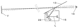
図9は、表示装置の従来技術を示している。当該従来技術による表示装置の光学系は、表示器15、反射鏡22から構成されており、反射鏡22の角度を調整することによりドライバー14の視点高さに応じて虚像表示Vが視認出来るように適切に調整するものである。
従来の表示装置では、より遠方に虚像表示を出して周囲の風景と一致させようとした場合、平均的な視点高さの観察者にとっては問題ないが、視点の高い観察者は虚像表示が下側に見えてしまい、逆に視点の低い観察者は虚像表示が上側にずれて見えるといった問題点があった。
そこで、本発明は、上記問題点に鑑みてなされたものであり、ドライバーがより遠方に虚像表示を認識させる場合であっても虚像表示と周囲の風景の高さを一致させやすい構造を、比較的容易に実現することが可能な表示装置の提供を目的としたものである。
上記目的を達成するために、本発明に係る表示装置は、
表示光を出射する表示器を備え、
前記表示器から入射された前記表示光を所定の角度に出射する透過性の第1の光学部材と、
前記第1の光学部材の出射面に対して入射面が対向するよう配設し、前記第1の光学部材から入射された前記表示光を所定の角度に出射する第2の光学部材と、
前記第1の光学部材と、前記第2の光学部材とを保持する保持部材と、
前記第1の光学部材と、前記第2の光学部材とが配設された相対する面に対して間隔を変化させられる可動手段と、
を備え、
前記第1の光学部材と、前記第2の光学部材との間隔を変化させることによって観察者への光路を所定の位置に補正すること、
を特徴とする。
表示光を出射する表示器を備え、
前記表示器から入射された前記表示光を所定の角度に出射する透過性の第1の光学部材と、
前記第1の光学部材の出射面に対して入射面が対向するよう配設し、前記第1の光学部材から入射された前記表示光を所定の角度に出射する第2の光学部材と、
前記第1の光学部材と、前記第2の光学部材とを保持する保持部材と、
前記第1の光学部材と、前記第2の光学部材とが配設された相対する面に対して間隔を変化させられる可動手段と、
を備え、
前記第1の光学部材と、前記第2の光学部材との間隔を変化させることによって観察者への光路を所定の位置に補正すること、
を特徴とする。
前記第1の光学部材と、前記第2の光学部材との内一方を固定し、他方を前記可動手段によって前記第1の光学部材と、前記第2の光学部材との間隔を変化させるための機構を有すること、
を特徴とする。
を特徴とする。
前記第1の光学部材と、前記第2の光学部材とは同一特性であり、且つ相反する向きで前記保持部材に配設されること、
を特徴とする。
を特徴とする。
前記第1の光学部材と、前記第2の光学部材とを互いに平行となるよう配設されること、
を特徴とする。
を特徴とする。
前記第1の光学部材と、前記第2の光学部材と、前記保持部材と、前記可動手段と、で構成される光路調整部と、前記表示器との間に反射部材が配設されること、
を特徴とする。
を特徴とする。
前記第1の光学部材と、前記第2の光学部材にホログラフィック光学素子を用いること、
を特徴とする。
を特徴とする。
本発明に係る表示装置によれば、ドライバーがより遠方に虚像表示を認識させる場合であっても虚像表示と周囲の風景の高さを一致させやすい構造を、比較的容易に実現することが可能な表示装置の提供をすることが出来る。
本発明に係る実施形態を、図面を参照して以下に説明する。
本発明の実施形態に係る表示装置は、車両用計器として構成されており、表示器が発した表示画像を車両のフロントガラスに投影し、ドライバーに対して虚像表示によって多岐に亘る情報を表示する。
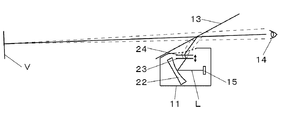
まず、図2を参照して、表示装置11を前記車両用計器として構成した場合を説明する。表示装置11は、図2に示すように、車両10のインパネ12に配設された表示ユニットである表示装置11が投射する表示光Lを投影部材である車両10のフロントガラス13で車両10のドライバー(観察者)14の方向に反射させ、虚像表示Vを行うものである。換言すれば、表示装置11は後述する表示器15から発せられる表示光Lをフロントガラス13に照射(投射)し、この照射によって得られた表示像(虚像表示)Vをドライバー14に視認させるものである。これによりドライバー14は、虚像表示Vを風景と重畳させて観察することが出来る。
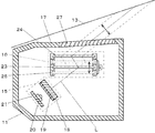
次に、表示装置11の物理的な構成を説明する。表示装置11は、図1に示すように表示器15と、反射鏡22と、光路調整部16と、ハウジング17とから主に構成されている。
表示器15は、回路基板21に実装された発光ダイオードからなる光源20と、この光源20からの照明光を透過して光を拡散させる光源20の前方側に位置する微細な凹凸からなる拡散面を有する光拡散板19と、拡散された光から表示光Lを発するようにTFT型の液晶表示素子(表示素子)18と、回路基板21と光源20と液晶表示素子18と光拡散板19とを収納する合成樹脂からなるケース体(図示せず)とから主に構成される。このことは、液晶表示素子18の背後側に光拡散板19が配設され、光拡散板19の背後に光源20が配設され、液晶表示素子18は、光源20から発せられる光により、所定情報(後述する表示すべき情報)を表示することを意味している。
なお、前記ケース体には、液晶表示素子18の表示領域(図示せず)を臨ませるための窓部が形成されている。そして、液晶表示素子18から発せられる表示光Lは前記窓部を通過して反射鏡22に導かれる構成となっている。
また液晶表示素子18は、図示しない制御回路によって表示すべき情報(例えば車速)を、数値等で表示する。なお、前記表示すべき情報は、車速にかぎらず、エンジン回転数等のあらゆる表示形態を採用できることは言うまでもない。
反射鏡22は、凹面を有するポリカーボネートからなる樹脂基板に反射層(金属)を蒸着形成してなるものである。かかる反射鏡22は、その反射層が表示器15並びに後述する光路調整部16に対向し、光路調整部16から臨める位置に傾斜状態にて配設させる。
また反射鏡22は、表示器15からの表示光Lを拡大しつつ、光路調整部16側へ反射(投射)されるものである。このことは、反射鏡22が表示器15によって発せられた表示光Lを拡大し、この拡大された表示光Lを光路調整部16に投射することを意味している。なお、反射鏡22は、ハウジング17に固定されている。
光路調整部16は、第1の光学部材23と、第2の光学部材24と、保持部材25と、ステッピングモータ26とから主に構成される。
第1の光学部材23と、第2の光学部材24は光学的に同一特性のホログラフィック光学素子(HOE:Holographic Optical Element)と、透光性の合成樹脂材料(例えばアクリル樹脂)を貼りあわせたものからなり、反射鏡22で反射される表示光Lが透過(通過)する光透過性部材としての機能を有している。係る第1の光学部材23と、第2の光学部材24は、入射する光に対して特定の角度で方向を変化させて出射するものである。上記のように前記ホログラフィック光学素子を使用することにより、透過前後の光軸設定や部材配置の自由度が飛躍的に向上し、光路調整部16のスペースを効率よく形成できる、また第1の光学部材23と、第2の光学部材24とを同一特性とすることで、一種類の光学部材を製造すればよく、製造コストを抑えることが可能である。
また第1の光学部材23と、第2の光学部材24は反射鏡22からの表示光Lが入射する方向に対して互いに平行(角度の許容範囲は±10deg以内で好ましくは±5deg以内)に設定され、相反する向きで保持部材25に配設される。このことは、反射鏡22で反射される表示光Lが第1の光学部材23を透過(通過)し、特定方向に出射角度が変化した表示光Lとなり、さらに出射角度が変化した表示光Lが第2の光学部材24を透過する際には元の角度(反射鏡22から第1の光学部材23に入射した角度)に戻されることを意味している。上記のように第1の光学部材23と、第2の光学部材24を相反する向きに設定することにより、第1の光学部材23に入射した表示光Lによる前記表示画像を完全に復元して第2の光学素子24から出射することが容易である。
保持部材25は、合成樹脂材料にて形成されてなる窓枠状のものであり、第1の光学部材23と、第2の光学部材24を保持する。
また保持部材25にはステッピングモータ26(可動手段)が取り付けられ、ステッピングモータ26を回転させることで、第1の光学部材23と、第2の光学部材24が配設された相対する面に対して垂直方向に移動させ、第1の光学部材23と、第2の光学部材24との間隔を変化させる。なお、第2の光学部材24は、保持部材25の最上部に固定され、第1の光学部材23と、第2の光学部材24の間隔を変化させるために移動(可動)する光学部材は第1の光学部材23とする。なお、光路調整部16は、ハウジング17に固定されている。
ハウジング17は、例えば黒色の合成樹脂材料にて形成されてなり、内部空間において、表示器15と、反射鏡22と、光路調整部16等を収納している。
またハウジング17は開口部が設けられ透光部である透光性カバー27が塞ぐように配設されてなる。かかる透光性カバー27は、透光性の合成樹脂材料(例えばアクリル樹脂)からなり、光路調整部16から出射される表示光Lが透過(通過)する光透過性部材としての機能を有している。そして、光路調整部16から出射されるとともに透光性カバー27から出射される表示光Lは、フロントガラス13に投影され、これによりドライバー14に対し虚像表示Vの表示が行われることになる。
以上の各部により、表示装置11が構成されている。次に、図4、図5を参照して、光路調整部16で調整した際の表示光Lの光路変化を説明する。第1の光学部材23と、第2の光学部材24は、上述のように光学的に同一仕様のものであり、互いに裏返した位置関係で配設される。これにより反射鏡22で反射され光路調整部16に達した表示光Lは、まず第1の光学部材23を通過して所定の角度だけ進行方向を変える。
次に第1の光学部材23と、第2の光学部材24との間隔だけ進んだ後に、第2の光学部材24を通過してまた元の方向(反射鏡22から第1の光学部材23に入射した角度)に戻る。この時、第1の光学部材23と第2の光学部材24の間を進んだ分だけ位置がずれる(光移動量M)ことになる。
この光移動量Mは第1の光学部材23の移動量に比例するが、第1の光学部材23を通過した後に変化する角度θを大きな設定にするほど第1の光学部材23の移動量は少なくすることが出来る。従って光路調整部16に入射/出射する光移動量Mに対して、第1の光学部材23の移動量の比率を2倍以下とすることで光路調整部16の占有スペースを抑えることが可能である。これを満たすために第1の光学部材23を通過した後の光軸方向と、第1の光学部材23の入射方向とのなす角度θは25deg以上とするのが妥当である。
またステッピングモータ26(可動手段)により第1の光学部材23の位置を適切に変化させることで、表示光Lの投射高さを調整することができる。ドライバー14は、スイッチ(図示しない)を操作し表示光Lが目の位置に反射されるように(即ち、虚像表示Vを視認できるように)第1の光学部材23の位置を調整すれば良い。
以上のように本実施形態では、表示光Lを発する液晶表示素子18と、表示光Lを反射させる反射鏡22と、反射鏡22で反射された表示光Lの光路を調整する光路調整部16と、光路調整部16で調整された表示光Lが通過する透光性カバー27とを有するハウジング17とを備え、透光性カバー27から出射される表示光Lをフロントガラス13に投影してドライバー14に対し表示を行う表示装置11において、光の進行方向を変える光路調整部16を反射鏡22とドライバー14側に配置し、第1の光学部材23と、第2の光学部材24との間隔を調節することによって表示光Lの高さ調整を行うものである。
従って、虚像表示Vが見える高さは、表示が遠方にあっても上下にずれることがなく、周囲の風景と一致させた拡張現実(AR:Augmented Reality)的な表示が容易になる。
また従来の表示装置11内の構造を大きく変えることなく、各種光学系及び表示系部品のサイズを拡大させる必要がない。このことは、コストや占有スペースを抑えられることを意味する。
また本実施形態では、所定情報(後述する表示すべき情報)を表示する表示素子を液晶表示素子18として説明したが、例えばDMD(Digital Micromirror Device)や、Laser-scanや、有機EL(Electro Luminescence)や、LCOS(Liquid Crystal On Silicon)であってもよい。
また本実施形態では、光路調整部16を水平に配設した構成であったが、反射鏡22で反射された表示光Lが入射出来ればどんな配置、角度であってもよい。
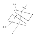
また本実施形態では、第1の光学部材23と、第2の光学部材24はホログラフィック光学素子(HOE:Holographic Optical Element)と、透光性の合成樹脂材料(例えばアクリル樹脂)からなるものであったが、例えば図6,7で示すようなくさび形状のプリズムや、平行線状にカットを入れたフレネルレンズであってもよい。
また本実施形態では、反射鏡22は、凹面を有するポリカーボネートからなる樹脂基板に反射層(金属)を蒸着形成してなるものであったが、拡大機能を別途持たせた上で平面を有するポリカーボネートからなる樹脂基板に反射層(金属)を蒸着形成してなるものであってもよい。また反射鏡22は実施形態により、複数個用いてもよい。
また本実施形態では、表示器15から発せられる表示光Lを反射鏡22で反射して光路調整部16に入射される例について説明したが、拡大機能を別途持たせた上で図8に示すように表示器15から直接、光路調整部16に表示光Lを入射させてもよい。
なお本実施形態では表示器15から発せられる表示光Lが、フロントガラス13に投射される例について説明したが、例えばフロントガラス13に表示光Lを良好にドライバー14方向に反射させるコンバイナフィルムを設けてもよいし、あるいはフロントガラス13とは別の専用の反射体に表示光Lを投射する構成としてもよい。
また本実施形態では、第1の光学部材23と、第2の光学部材24は互いに平行に設定される例について説明したが、表示光Lを良好にドライバー14方向に反射させることが可能であれば、第1の光学部材23と、第2の光学部材24とでなす角度は平行でなく設置してもよい。
本発明は、表示器が発した表示画像を車両のフロントガラス等の投影部材に投影し虚像表示を行う表示装置に利用可能である。
10 車両
11 表示装置
12 インパネ
13 フロントガラス(投影部材)
14 ドライバー(観察者)
15 表示器
16 光路調整部
17 ハウジング
18 液晶表示素子
19 光拡散板
20 光源
21 回路基板
22 反射鏡
23 第1の光学部材
24 第2の光学部材
25 保持部材
26 ステッピングモータ
27 透光性カバー
L 表示光
M 光移動量
V 虚像表示
θ 第1の光学部材23を通過した後の光軸方向と、第1の光学部材23の入射方向とのなす角度
11 表示装置
12 インパネ
13 フロントガラス(投影部材)
14 ドライバー(観察者)
15 表示器
16 光路調整部
17 ハウジング
18 液晶表示素子
19 光拡散板
20 光源
21 回路基板
22 反射鏡
23 第1の光学部材
24 第2の光学部材
25 保持部材
26 ステッピングモータ
27 透光性カバー
L 表示光
M 光移動量
V 虚像表示
θ 第1の光学部材23を通過した後の光軸方向と、第1の光学部材23の入射方向とのなす角度
Claims (6)
- 表示光を出射する表示器を備え、
前記表示器から入射された前記表示光を所定の角度に出射する透過性の第1の光学部材と、
前記第1の光学部材の出射面に対して入射面が対向するよう配設し、前記第1の光学部材から入射された前記表示光を所定の角度に出射する第2の光学部材と、
前記第1の光学部材と、前記第2の光学部材とを保持する保持部材と、
前記第1の光学部材と、前記第2の光学部材とが配設された相対する面に対して間隔を変化させられる可動手段と、
を備え、
前記第1の光学部材と、前記第2の光学部材との間隔を変化させることによって観察者への光路を所定の位置に補正すること、
を特徴とする表示装置。 - 前記第1の光学部材と、前記第2の光学部材との内一方を固定し、他方を前記可動手段によって前記第1の光学部材と、前記第2の光学部材との間隔を変化させるための機構を有すること、
を特徴とする請求項1に記載の表示装置。 - 前記第1の光学部材と、前記第2の光学部材とは同一特性であり、且つ相反する向きで前記保持部材に配設されること、
を特徴とする請求項1から2のいずれかに記載の表示装置。 - 前記第1の光学部材と、前記第2の光学部材とを互いに平行となるよう配設されること、
を特徴とする請求項1から3のいずれかに記載の表示装置。 - 前記第1の光学部材と、前記第2の光学部材と、前記保持部材と、前記可動手段と、で構成される光路調整部と、前記表示器との間に反射部材が配設されること、
を特徴とする請求項1から4のいずれかに記載の表示装置。 - 前記第1の光学部材と、前記第2の光学部材にホログラフィック光学素子を用いること、
を特徴とする請求項1から5のいずれかに記載の表示装置。
Applications Claiming Priority (2)
| Application Number | Priority Date | Filing Date | Title |
|---|---|---|---|
| JP2013-198024 | 2013-09-25 | ||
| JP2013198024A JP6153079B2 (ja) | 2013-09-25 | 2013-09-25 | 表示装置 |
Publications (1)
| Publication Number | Publication Date |
|---|---|
| WO2015045936A1 true WO2015045936A1 (ja) | 2015-04-02 |
Family
ID=52743077
Family Applications (1)
| Application Number | Title | Priority Date | Filing Date |
|---|---|---|---|
| PCT/JP2014/074369 Ceased WO2015045936A1 (ja) | 2013-09-25 | 2014-09-16 | 表示装置 |
Country Status (2)
| Country | Link |
|---|---|
| JP (1) | JP6153079B2 (ja) |
| WO (1) | WO2015045936A1 (ja) |
Cited By (1)
| Publication number | Priority date | Publication date | Assignee | Title |
|---|---|---|---|---|
| DE102017130376A1 (de) | 2017-12-18 | 2019-06-19 | Valeo Schalter Und Sensoren Gmbh | Anzeigevorrichtung als Head-up Display mit einfacher Eyebox-Verschiebung |
Families Citing this family (3)
| Publication number | Priority date | Publication date | Assignee | Title |
|---|---|---|---|---|
| CN109633901A (zh) * | 2018-12-09 | 2019-04-16 | 中国航空工业集团公司洛阳电光设备研究所 | 一种汽车平显像源构型及像源调整机构 |
| CN111367079A (zh) * | 2020-02-19 | 2020-07-03 | 浙江零跑科技有限公司 | 一种通过曲面屏反射的抬头显示系统 |
| JP2023173159A (ja) * | 2022-05-25 | 2023-12-07 | 株式会社ジャパンディスプレイ | ヘッドアップディスプレイ及び表示装置 |
Citations (3)
| Publication number | Priority date | Publication date | Assignee | Title |
|---|---|---|---|---|
| JPS60183240A (ja) * | 1984-03-02 | 1985-09-18 | Nissan Motor Co Ltd | 車両用表示装置 |
| JPH02186319A (ja) * | 1989-01-13 | 1990-07-20 | Fujitsu Ltd | 表示システム |
| JP2006208583A (ja) * | 2005-01-26 | 2006-08-10 | Denso Corp | 表示装置 |
-
2013
- 2013-09-25 JP JP2013198024A patent/JP6153079B2/ja not_active Expired - Fee Related
-
2014
- 2014-09-16 WO PCT/JP2014/074369 patent/WO2015045936A1/ja not_active Ceased
Patent Citations (3)
| Publication number | Priority date | Publication date | Assignee | Title |
|---|---|---|---|---|
| JPS60183240A (ja) * | 1984-03-02 | 1985-09-18 | Nissan Motor Co Ltd | 車両用表示装置 |
| JPH02186319A (ja) * | 1989-01-13 | 1990-07-20 | Fujitsu Ltd | 表示システム |
| JP2006208583A (ja) * | 2005-01-26 | 2006-08-10 | Denso Corp | 表示装置 |
Cited By (1)
| Publication number | Priority date | Publication date | Assignee | Title |
|---|---|---|---|---|
| DE102017130376A1 (de) | 2017-12-18 | 2019-06-19 | Valeo Schalter Und Sensoren Gmbh | Anzeigevorrichtung als Head-up Display mit einfacher Eyebox-Verschiebung |
Also Published As
| Publication number | Publication date |
|---|---|
| JP2015064472A (ja) | 2015-04-09 |
| JP6153079B2 (ja) | 2017-06-28 |
Similar Documents
| Publication | Publication Date | Title |
|---|---|---|
| CN103454704B (zh) | 显示方法 | |
| EP3185061B1 (en) | Projection device and head-up display device | |
| JP5741251B2 (ja) | 虚像表示装置 | |
| JP6589890B2 (ja) | ヘッドアップディスプレイ装置 | |
| JP2010256867A (ja) | ヘッドアップディスプレイ及び画像表示方法 | |
| WO2016208379A1 (ja) | スクリーン装置及びヘッドアップディスプレイ装置 | |
| JP6414131B2 (ja) | 投影装置及びヘッドアップディスプレイ装置 | |
| JP6717264B2 (ja) | 虚像表示装置、中間像形成部および画像表示光生成ユニット | |
| JP7838111B2 (ja) | ヘッドアップディスプレイ装置、ヘッドアップディスプレイ方法、および車両 | |
| JP2020016675A (ja) | 虚像表示装置 | |
| JP6153079B2 (ja) | 表示装置 | |
| JPWO2019044730A1 (ja) | ヘッドアップディスプレイ装置 | |
| WO2017061000A1 (ja) | ヘッドアップディスプレイ装置 | |
| JP2017049570A (ja) | ミラーユニット | |
| TWI494603B (zh) | 可攜式抬頭顯示裝置 | |
| WO2019087714A1 (ja) | ヘッドアップディスプレイ装置 | |
| JP7155700B2 (ja) | 表示装置 | |
| WO2020004093A1 (ja) | ヘッドアップディスプレイ装置 | |
| JP2018530771A (ja) | コンパクトなヘッドアップディスプレイ | |
| JP2017181786A (ja) | ヘッドアップディスプレイ装置 | |
| JP6683149B2 (ja) | ヘッドアップディスプレイ装置 | |
| JP2018163260A (ja) | 画像表示装置、虚像表示装置、移動体 | |
| JP2022026522A (ja) | ヘッドアップディスプレイ装置 | |
| JP2017227681A (ja) | ヘッドアップディスプレイ装置 | |
| JP2017044926A (ja) | ミラーユニット |
Legal Events
| Date | Code | Title | Description |
|---|---|---|---|
| 121 | Ep: the epo has been informed by wipo that ep was designated in this application |
Ref document number: 14848275 Country of ref document: EP Kind code of ref document: A1 |
|
| NENP | Non-entry into the national phase |
Ref country code: DE |
|
| 122 | Ep: pct application non-entry in european phase |
Ref document number: 14848275 Country of ref document: EP Kind code of ref document: A1 |