WO2015044996A1 - Endoscope device and method for controlling endoscope device - Google Patents
Endoscope device and method for controlling endoscope device Download PDFInfo
- Publication number
- WO2015044996A1 WO2015044996A1 PCT/JP2013/075625 JP2013075625W WO2015044996A1 WO 2015044996 A1 WO2015044996 A1 WO 2015044996A1 JP 2013075625 W JP2013075625 W JP 2013075625W WO 2015044996 A1 WO2015044996 A1 WO 2015044996A1
- Authority
- WO
- WIPO (PCT)
- Prior art keywords
- image
- focus
- unit
- vivo
- freeze
- Prior art date
Links
Images


Classifications
-
- A—HUMAN NECESSITIES
- A61—MEDICAL OR VETERINARY SCIENCE; HYGIENE
- A61B—DIAGNOSIS; SURGERY; IDENTIFICATION
- A61B1/00—Instruments for performing medical examinations of the interior of cavities or tubes of the body by visual or photographical inspection, e.g. endoscopes; Illuminating arrangements therefor
- A61B1/00002—Operational features of endoscopes
- A61B1/00004—Operational features of endoscopes characterised by electronic signal processing
- A61B1/00009—Operational features of endoscopes characterised by electronic signal processing of image signals during a use of endoscope
-
- A—HUMAN NECESSITIES
- A61—MEDICAL OR VETERINARY SCIENCE; HYGIENE
- A61B—DIAGNOSIS; SURGERY; IDENTIFICATION
- A61B1/00—Instruments for performing medical examinations of the interior of cavities or tubes of the body by visual or photographical inspection, e.g. endoscopes; Illuminating arrangements therefor
- A61B1/00002—Operational features of endoscopes
- A61B1/00004—Operational features of endoscopes characterised by electronic signal processing
- A61B1/00006—Operational features of endoscopes characterised by electronic signal processing of control signals
-
- A—HUMAN NECESSITIES
- A61—MEDICAL OR VETERINARY SCIENCE; HYGIENE
- A61B—DIAGNOSIS; SURGERY; IDENTIFICATION
- A61B1/00—Instruments for performing medical examinations of the interior of cavities or tubes of the body by visual or photographical inspection, e.g. endoscopes; Illuminating arrangements therefor
- A61B1/00002—Operational features of endoscopes
- A61B1/0002—Operational features of endoscopes provided with data storages
-
- A—HUMAN NECESSITIES
- A61—MEDICAL OR VETERINARY SCIENCE; HYGIENE
- A61B—DIAGNOSIS; SURGERY; IDENTIFICATION
- A61B1/00—Instruments for performing medical examinations of the interior of cavities or tubes of the body by visual or photographical inspection, e.g. endoscopes; Illuminating arrangements therefor
- A61B1/00002—Operational features of endoscopes
- A61B1/00043—Operational features of endoscopes provided with output arrangements
- A61B1/00045—Display arrangement
- A61B1/0005—Display arrangement combining images e.g. side-by-side, superimposed or tiled
-
- A—HUMAN NECESSITIES
- A61—MEDICAL OR VETERINARY SCIENCE; HYGIENE
- A61B—DIAGNOSIS; SURGERY; IDENTIFICATION
- A61B1/00—Instruments for performing medical examinations of the interior of cavities or tubes of the body by visual or photographical inspection, e.g. endoscopes; Illuminating arrangements therefor
- A61B1/00163—Optical arrangements
- A61B1/00188—Optical arrangements with focusing or zooming features
-
- A—HUMAN NECESSITIES
- A61—MEDICAL OR VETERINARY SCIENCE; HYGIENE
- A61B—DIAGNOSIS; SURGERY; IDENTIFICATION
- A61B1/00—Instruments for performing medical examinations of the interior of cavities or tubes of the body by visual or photographical inspection, e.g. endoscopes; Illuminating arrangements therefor
- A61B1/04—Instruments for performing medical examinations of the interior of cavities or tubes of the body by visual or photographical inspection, e.g. endoscopes; Illuminating arrangements therefor combined with photographic or television appliances
- A61B1/045—Control thereof
-
- A—HUMAN NECESSITIES
- A61—MEDICAL OR VETERINARY SCIENCE; HYGIENE
- A61B—DIAGNOSIS; SURGERY; IDENTIFICATION
- A61B1/00—Instruments for performing medical examinations of the interior of cavities or tubes of the body by visual or photographical inspection, e.g. endoscopes; Illuminating arrangements therefor
- A61B1/06—Instruments for performing medical examinations of the interior of cavities or tubes of the body by visual or photographical inspection, e.g. endoscopes; Illuminating arrangements therefor with illuminating arrangements
- A61B1/0655—Control therefor
-
- G—PHYSICS
- G02—OPTICS
- G02B—OPTICAL ELEMENTS, SYSTEMS OR APPARATUS
- G02B7/00—Mountings, adjusting means, or light-tight connections, for optical elements
- G02B7/28—Systems for automatic generation of focusing signals
- G02B7/36—Systems for automatic generation of focusing signals using image sharpness techniques, e.g. image processing techniques for generating autofocus signals
-
- A—HUMAN NECESSITIES
- A61—MEDICAL OR VETERINARY SCIENCE; HYGIENE
- A61B—DIAGNOSIS; SURGERY; IDENTIFICATION
- A61B1/00—Instruments for performing medical examinations of the interior of cavities or tubes of the body by visual or photographical inspection, e.g. endoscopes; Illuminating arrangements therefor
- A61B1/06—Instruments for performing medical examinations of the interior of cavities or tubes of the body by visual or photographical inspection, e.g. endoscopes; Illuminating arrangements therefor with illuminating arrangements
- A61B1/0661—Endoscope light sources
- A61B1/0669—Endoscope light sources at proximal end of an endoscope
-
- A—HUMAN NECESSITIES
- A61—MEDICAL OR VETERINARY SCIENCE; HYGIENE
- A61B—DIAGNOSIS; SURGERY; IDENTIFICATION
- A61B1/00—Instruments for performing medical examinations of the interior of cavities or tubes of the body by visual or photographical inspection, e.g. endoscopes; Illuminating arrangements therefor
- A61B1/06—Instruments for performing medical examinations of the interior of cavities or tubes of the body by visual or photographical inspection, e.g. endoscopes; Illuminating arrangements therefor with illuminating arrangements
- A61B1/07—Instruments for performing medical examinations of the interior of cavities or tubes of the body by visual or photographical inspection, e.g. endoscopes; Illuminating arrangements therefor with illuminating arrangements using light-conductive means, e.g. optical fibres
-
- G—PHYSICS
- G02—OPTICS
- G02B—OPTICAL ELEMENTS, SYSTEMS OR APPARATUS
- G02B23/00—Telescopes, e.g. binoculars; Periscopes; Instruments for viewing the inside of hollow bodies; Viewfinders; Optical aiming or sighting devices
- G02B23/24—Instruments or systems for viewing the inside of hollow bodies, e.g. fibrescopes
- G02B23/2407—Optical details
- G02B23/2423—Optical details of the distal end
- G02B23/243—Objectives for endoscopes
- G02B23/2438—Zoom objectives
Definitions
- the present invention relates to an endoscope apparatus, a control method of the endoscope apparatus, and the like.
- an imaging apparatus such as an endoscope
- a pan-focused image is required because it does not affect the doctor's diagnosis. Therefore, in the endoscope, such performance is achieved by widening the depth of field by using an optical system having a relatively large f-number.
- an imaging element with a high number of pixels of about several hundreds of thousands is used. Since the permissible circle of confusion decreases with the pixel pitch in the high pixel imaging device, it is necessary to reduce the F number, and the width of the depth of field of the imaging device becomes narrow. This makes it difficult to maintain pan focus.
- Patent Document 1 discloses an endoscope apparatus in which a drive unit for driving a lens position of an objective optical system is provided in an imaging unit of an endoscope and autofocus (hereinafter referred to as AF) is performed on a subject. It is done.
- AF autofocus
- a doctor who performs a medical examination with an endoscope acquires a freeze image (still image) by operation of a freeze switch or the like, and performs detailed observation with the freeze image.
- this freeze image is acquired by an endoscope that performs AF.
- an AF is performed by moving the objective lens of the optical system in a direction in which the contour signal of the subject is slightly high, so an image which is not in focus on the subject is generated until AF is completed. I will. Therefore, when the obtained freeze image is an image which is not in focus on the subject, the doctor needs to perform the operation of the freeze switch again, and there is a problem that the complexity of the work is increased.
- an endoscope apparatus capable of displaying a freeze image focused on a subject, a control method of the endoscope apparatus, and the like can be provided.
- One aspect of the present invention relates to an in-vivo image acquiring unit for acquiring a plurality of in-vivo images including an image of the in-vivo object obtained by imaging the in-vivo object by an imaging optical system;
- An in-focus evaluation value calculation unit that calculates an in-focus evaluation value representing a degree of in-focus, a focus control unit that controls in-focus operation of the imaging optical system based on the in-focus evaluation value, and the in-focus evaluation value
- a freeze image setting unit which selects at least one in-vivo image from among the plurality of in-vivo images based on the degree of focusing represented by and setting the selected at least one in-vivo image as a freeze image; It relates to the endoscope apparatus which contains.
- the in-focus operation is controlled based on the in-focus evaluation value, and at least one in-vivo image among the plurality of in-vivo images based on the in-focus degree represented by the in-focus evaluation value. Is set as a freeze image. This makes it possible to display a freeze image focused on the subject.
- a plurality of in-vivo images including an image of the in-vivo subject obtained by imaging the in-vivo subject by the imaging optical system are acquired, and focusing is performed on each in-vivo image of the plurality of in-vivo images
- An in-focus evaluation value representing a degree is calculated, and the in-focus operation of the imaging optical system is controlled based on the in-focus evaluation value, and the in-focus evaluation value is expressed based on the in-focus evaluation value.
- the present invention relates to a control method of an endoscope apparatus which selects at least one in-vivo image from among a plurality of in-vivo images and sets the selected at least one in-vivo image as a freeze image.
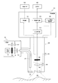
- FIG. 1 is a structural example of the endoscope apparatus in 1st Embodiment.
- Fig. 2 shows a detailed configuration example of the rotary color filter.
- Fig. 3 shows an example of spectral characteristics of a color filter.
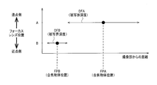
- FIG. 4 is an explanatory view of the relationship between the position of the focus lens and the in-focus object position.
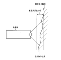
- FIG. 5 is an explanatory view of the depth of field when the in-focus object position is on the near point side.
- FIG. 6 is an explanatory view of the depth of field when the in-focus object position is on the far point side.
- FIG. 7 is a detailed configuration example of the image processing unit.
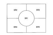
- FIG. 8 is an explanatory diagram of area division performed by the attention area setting unit.
- FIG. 8 is an explanatory diagram of area division performed by the attention area setting unit.
- FIG. 9 is an explanatory diagram of an operation performed by the freeze image setting unit.
- FIG. 10 is an explanatory view of a modification of the operation performed by the freeze image setting unit;
- FIG. 11 is an explanatory diagram of a second modified example of the operation performed by the freeze image setting unit.
- FIG. 12 is a flowchart example of the operation performed by the lens position control unit.
- FIGS. 13A and 13B are examples of display images when two freeze candidate images are displayed.
- FIG. 14: is a structural example of the endoscope apparatus in 2nd Embodiment.
- FIG. 15 is an explanatory diagram of an operation performed by the freeze image setting unit.
- the width of the depth of field narrows, making it difficult to focus (focus on) a desired subject.
- the width of the depth of field tends to be further narrowed by increasing the imaging magnification of the imaging unit or shortening the distance from the imaging unit to the subject. Even a slight movement of the object position makes it easy to deviate from the depth of field range.
- the freeze image (still image) is displayed on the display unit by operating the freeze switch provided on the operation unit. Also in such a case, when the depth of field is narrow, the subject in the region of interest is easily out of the range of depth of field. Therefore, in order to obtain an image focused on the subject in the attention area, the operation of the freeze switch has to be repeated many times, and the workability is deteriorated.
- captured images of a plurality of frames are stored, and among the stored captured images, a captured image focused on a subject is displayed as a freeze image on the display unit.
- the user can easily obtain a freeze image focused on the subject simply by pressing the freeze switch without being aware of whether or not the subject is in focus. It can be done easily.
- the case of performing two-focus switching will be described as an example.
- 2-focus switching in general, although the AF mechanism can be simplified, it is difficult to obtain a freeze image focused on the subject because the degree of freedom of focus adjustment is low and it becomes difficult to perform high-definition focusing operation. There is a tendency.
- the captured image focused from among the captured images of a plurality of frames is selected as the freeze image, the freeze image focused on the subject can be obtained even with bifocal switching.
- the case of performing the continuous AF method will be described as an example. In the continuous AF method, since the degree of freedom of focus adjustment is higher than the two-focus switching, high-definition focusing operation is possible.
- FIG. 1 shows a configuration example of an endoscope apparatus according to the first embodiment.
- the endoscope apparatus includes a light source unit 100, an imaging unit 200, a control device 300 (processor unit), a display unit 400, and an external I / F unit 500.
- the light source unit 100 includes a white light source 110, a light source diaphragm 120, a light source diaphragm driving unit 130 for driving the light source diaphragm 120, and a rotational color filter 140 having filters of a plurality of spectral transmittances.
- the light source unit 100 also includes a rotary drive unit 150 for driving the rotary color filter 140, and a condenser lens 160 for condensing light transmitted through the rotary color filter 140 on the incident end face of the light guide fiber 210.
- the light source diaphragm driving unit 130 adjusts the light amount of the illumination light by opening and closing the light source diaphragm 120 based on the control signal from the control unit 340 of the control device 300.
- a detailed configuration example of the rotary color filter 140 is shown in FIG.
- the rotating color filter 140 is composed of three primary color red (abbreviated as R) filters 701, a green (abbreviated as G) filter 702, a blue (abbreviated as B) filter 703, and a rotating motor 704. There is.
- FIG. 3 shows an example of the spectral characteristics of these color filters 701-703.
- the rotation drive unit 150 rotates the rotation color filter 140 at a predetermined rotation speed in synchronization with the imaging period of the imaging device 260 based on the control signal from the control unit 340. For example, if the rotary color filter 140 is rotated 20 times per second, each color filter will cross incident white light at intervals of 1/60 second. In this case, the imaging device 260 completes the imaging and transfer of the image signal at an interval of 1/60 of a second.
- the imaging device 260 is, for example, a monochrome single-plate imaging device, and is configured of, for example, a CCD, a CMOS image sensor, or the like. That is, in the present embodiment, imaging in a plane-sequential method is performed in which images of respective primary colors (R, G, or B) of three primary colors are captured at an interval of 1/60 second.
- the imaging unit 200 is formed to be elongated and bendable, for example, to allow insertion into a body cavity.
- the imaging unit 200 diffuses the light guided to the tip by the light guide fiber 210 for guiding the light collected by the light source unit 100 to the illumination lens 220 and irradiates the observation target with the light And an illumination lens 220. Further, the imaging unit 200 discretely positions the objective lens 230 for condensing the reflected light returning from the observation target, the focus lens 240 (focus adjustment lens) for adjusting the focal position, and the focus lens 240. And an imaging element 260 for detecting the collected reflected light.
- the switching unit 250 is, for example, a VCM (Voice Coil Motor), and is connected to the focus lens 240.
- the switching unit 250 discretely adjusts the in-focus object position, which is the position of the object in focus, by switching the position of the focus lens 240 at a plurality of discrete positions. The relationship between the position of the focus lens 240 and the in-focus object position will be described later with reference to FIG.
- the imaging unit 200 is provided with a freeze switch 270 for the user to issue a freeze instruction.
- the freeze switch 270 can input / cancel a freeze instruction signal.
- the freeze switch 270 outputs a freeze instruction signal to the control unit 340.
- the control device 300 controls each part of the endoscope apparatus and performs image processing.
- the control device 300 includes an A / D conversion unit 310, a lens position control unit 320 (in a broad sense, a focus control unit), an image processing unit 330, and a control unit 340.
- the image signal converted into the digital signal by the A / D converter 310 is transferred to the image processor 330.
- the image signal processed by the image processing unit 330 is transferred to the display unit 400. Further, the image processing unit 330 transfers the contrast value calculated from the image signal to the lens position control unit 320.
- the lens position control unit 320 transfers the control signal to the switching unit 250 to change the position of the focus lens 240. Further, the lens position control unit 320 transfers a control signal indicating the position of the focus lens 240 to the image processing unit 330.
- the control unit 340 controls each part of the endoscope apparatus. Specifically, the control unit 340 synchronizes the light source stop driving unit 130, the lens position control unit 320, and the image processing unit 330.
- control unit 340 is connected to the freeze switch 270 and the external I / F unit 500, and transfers a freeze instruction signal to the image processing unit 330. Further, the control unit 340 transfers the degree of opening L representing the degree of opening of the light source stop to the lens position control unit 320.
- the display unit 400 is a display device capable of displaying moving images, and is configured of, for example, a CRT, a liquid crystal monitor, or the like.
- the external I / F unit 500 is an interface for performing input from the user to the endoscope apparatus.
- the external I / F unit 500 may have a freeze button (not shown) that can issue a freeze instruction.
- the user can also issue a freeze instruction from the external I / F unit 500 (the freeze button has the same function as the freeze switch 270 of the imaging unit 200).
- the freeze instruction signal from the external I / F unit 500 is output to the control unit 340.
- the external I / F unit 500 also includes a power switch for turning on / off the power, a mode switching button for switching the shooting mode and various other modes, and the like.
- the image processing unit 330 performs image processing on the captured image converted into a digital signal by the A / D conversion unit 310. Specifically, pre-processing and synchronization processing, calculation processing of a contrast value (focus evaluation value in a broad sense), selection processing of a freeze image, post-processing and the like are performed.
- the image processing unit 330 outputs the post-processed freeze image or moving image (captured image) to the display unit 400, and outputs the contrast value to the lens position control unit 320. Details of the image processing unit 330 will be described later with reference to FIG.
- the lens position control unit 320 controls the switching unit 250 based on the contrast value input from the image processing unit 330 and the opening degree L of the light source diaphragm input from the control unit 340.
- AF control is performed. Details of the lens position control unit 320 will be described later with reference to FIG.
- the imaging method is the surface sequential method
- the present embodiment is not limited to this, and, for example, imaging elements such as primary color Bayer, complementary single plate, two primary colors, and three primary colors It is good also as an imaging method using.
- imaging elements such as primary color Bayer, complementary single plate, two primary colors, and three primary colors It is good also as an imaging method using.
- normal light observation in which the illumination light is white light
- the present embodiment is not limited to this.
- NBI Narrow
- NBI NBI (Narrow) in which light in a narrower band than white light is illumination light It is good also as special light observation represented by Band Imaging etc.
- the position of the focus lens 240 is a point FPB close to the imaging unit 200 (hereinafter referred to as a point A) corresponding to a point FPA (hereinafter referred to as far point) where the in-focus object position is far from the imaging unit 200.
- a point A corresponding to a point FPA
- far point where the in-focus object position is far from the imaging unit 200.
- point B corresponding to point.
- the range of depth of field required for endoscopic observation is achieved by switching the focus lens position.
- the range of the depth of field that can be realized by combining the respective ranges of depth of field DFA and DFB when the lens position is switched to A and B includes 2 to 70 mm.
- the in-focus object position is the position of an object (subject) to which the imaging unit 200 is in focus, and is represented by, for example, the distance from the tip of the imaging unit 200 to the object on the optical axis of the imaging optical system. . More specifically, the in-focus object position is the position of the object plane corresponding to the image plane when the light receiving surface of the image sensor 260 matches the image plane. Note that if it is a position within the depth of field of the imaging unit 200, it can be considered that the subject is in focus, so the in-focus object position is set to an arbitrary position within the depth of field It is also good.
- the in-focus object positions FPA and FPB in FIG. 4 may be set to any position within the depth of field DFA or DFB, respectively, and the in-focus object position and the subject are obtained by switching the position of the focus lens 240. It does not change that the depth of field is switched.
- the position of the focus lens 240 is the position of the focus lens 240 in the imaging optical system, and is represented by, for example, the distance from the reference point in the imaging optical system to the focus lens 240.
- the reference point is, for example, the position of the lens closest to the object among the lenses constituting the imaging optical system, or the position of the light receiving surface of the image sensor 260.
- the focus adjustment lens may be a focus lens in two-group drive in which the zoom lens and the focus lens are independent, or the zoom lens is a zoom lens in one-group drive in which both zoom magnification adjustment and focus adjustment are performed. It is also good.
- FIG. 7 shows a detailed configuration example of the image processing unit 330 in the first embodiment.
- the image processing unit 330 includes a preprocessing unit 331, a synchronization unit 332, a selection unit 333, a storage unit 334, an attention area setting unit 335, a contrast value calculation unit 336, a freeze image setting unit 337, And a processing unit 338.
- the A / D conversion unit 310 is connected to the pre-processing unit 331.
- the preprocessing unit 331 is connected to the synchronization unit 332.
- the synchronization unit 332 is connected to the selection unit 333, the storage unit 334, and the attention area setting unit 335.
- the selection unit 333 is connected to the post-processing unit 338.
- the storage unit 334 is connected to the freeze image setting unit 337.
- the attention area setting unit 335 is connected to the contrast value calculation unit 336.
- the contrast value calculation unit 336 is connected to the freeze image setting unit 337 and the lens position control unit 320.
- the lens position control unit 320 is connected to the freeze image setting unit 337.
- the freeze image setting unit 337 is connected to the selection unit 333.
- the post-processing unit 338 is connected to the display unit 400.
- the control unit 340 is bi-directionally connected to each unit, and controls these units.
- the pre-processing unit 331 performs OB clamp processing and gain processing on an image signal input from the A / D conversion unit using an OB clamp value, a gain correction value, and a WB coefficient value stored in advance in the control unit 340. Perform correction processing and WB correction processing.
- the preprocessing unit 331 transfers the image signal after preprocessing to the synchronization unit 332.
- the synchronization unit 332 synchronizes the plane-sequential image signal with the image signal processed by the pre-processing unit 331 based on the control signal of the control unit 340. Specifically, the synchronization unit 332 accumulates the image signals of the respective color lights (R or G or B) input frame-sequentially one frame at a time, and simultaneously reads the image signals of the respective color lights accumulated. That is, the three images of R, G, and B are synchronized to a captured image of one frame.
- the respective synchronized three-frame captured images are sequentially output.
- the synchronization unit 332 transfers the synchronized captured image (image signal) to the selection unit 333 and the attention area setting unit 335.
- the synchronization unit 332 transfers the captured image to the storage unit 334 based on the freeze instruction signal input from the control unit 340. Specifically, when the freeze instruction signal is input from the control unit 340, the synchronization unit 332 stops the transfer of the captured image to the storage unit 334. On the other hand, when the freeze instruction signal is released, the captured image is transferred to the storage unit 334.
- the storage unit 334 is configured of a frame memory capable of storing a plurality of frames of the captured image transferred from the synchronization unit 332.
- the storage unit 334 includes a frame memory capable of storing captured images of N frames (N is a natural number of 2 or more (including its value)) in time series.
- the storage unit 334 sequentially stores the input captured image, and deletes the oldest captured image of the stored N frames and stores a new captured image after the N + 1th frame.
- the attention area setting unit 335 sets an attention area for calculating a contrast value for the captured image transferred from the synchronization unit 332. For example, as shown in FIG. 8, the captured image is divided into first to fifth regions BR1 to BR5 (a plurality of regions in a broad sense), and brightness information of each region is calculated. The brightness information is, for example, a value obtained by summing the luminance value of each pixel in the area.
- the attention area setting unit 335 determines whether the brightness information of each area is equal to or more than a threshold, and sets an area equal to or more than the threshold as an attention area.
- the attention area setting unit 335 transfers the information on the set attention area and the captured image to the contrast value calculation unit 336. If the focused area can not be set because the captured image does not have sufficient brightness (if there is no area where the brightness information exceeds the threshold), the control signal indicating that the focused area does not exist is calculated as the contrast value Transfer to section 336.
- the present embodiment is not limited to this.
- the brightest area among the areas BR1 to BR5 It may be set as an attention area.
- the present invention is not limited to this, and the user may set an attention area in advance via the external I / F unit 500.
- the attention area is not set, the entire screen may be set as the attention area.
- the region-of-interest setting unit 335 has a region-of-interest detection unit that detects a region having a unique feature amount compared with the periphery of a lesion region or the like.
- the attention area for example, the center of the screen or the opposite side of the dark area (for example, in FIG. 8, when the area BR2 is the darkest, the area BR5 is the attention area.
- the center (area BR1) is the most.
- the brightest area among the peripheral areas BR2 to BR5 is the area of interest
- the lesion area for example, red, amber, special light
- an area having a feature value different from the peripheral for example, red
- temporal brightness An area or the like with small variation may be set as the area of interest.
- the contrast value calculation unit 336 calculates the contrast value of the attention area from the information of the attention area and the captured image. For example, the contrast value of an arbitrary channel may be calculated for the captured image transferred from the attention area setting unit 335. Alternatively, a luminance signal may be generated from pixel values of three channels of R, G, and B, and a contrast value may be calculated from the pixel values of the generated luminance signal. For example, the contrast value calculation unit 336 performs arbitrary high-pass filter processing on all pixels included in the region of interest, and calculates the contrast value by adding the high-pass filter output value of each pixel in the region of interest. When the control signal indicating that the attention area is not set in the captured image is input, the contrast value calculation unit 336 sets 0 as the contrast value. The contrast value calculation unit 336 transfers the contrast value of the attention area to the freeze image setting unit 337 and the lens position control unit 320.
- the contrast value calculation unit 336 may be configured to have a bright spot removal unit.
- the bright spot removal unit performs threshold processing on the pixel values of arbitrary channels or luminance signals in all the pixels included in the target area, and determines the bright spots for pixels whose pixel values are equal to or greater than the threshold.
- the contrast value calculation unit 336 removes the pixels determined to be bright spots from the addition process. Thereby, the influence of the bright spot on the contrast value can be reduced.
- the contrast value is described above as the value obtained by adding the output value of the high pass filter, the present embodiment is not limited to this.
- the number of pixels whose output value of the high pass filter is equal to or more than the threshold value is contrasted It may be calculated as a value. In this way, the contrast value can be used as a value indicating the size of the area in focus on the subject.
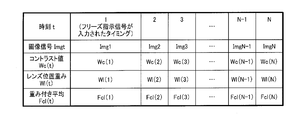
- the freeze image setting unit 337 extracts a captured image focused on the subject from among the plurality of captured images stored in the storage unit 334. Specifically, the freeze image setting unit 337 associates the contrast value input from the contrast value calculation unit 336 with the position of the focus lens 240 input from the lens position control unit 320, and sets N each in time series. It has a memory (not shown) that can be stored. When the freeze instruction signal is input from the control unit 340, the memory (not shown) holds the past N contrast values and the lens position from the timing when the freeze instruction signal is input.
- the contrast value of the attention area of the captured image Imgt is Wc (t)
- the position of the focus lens 240 at the timing when the captured image Imgt is captured A or B is stored in association with each other in a memory (not shown).
- the captured image captured in the above is set as a freeze candidate image (captured image not hatched in FIG. 9). Then, the captured image having the largest contrast value is extracted as a freeze image from the freeze candidate images, and the freeze image is transferred to the selection unit 333.
- the freeze image setting unit 337 detects the motion blur Wb (t) representing the blur amount of the captured image from the correlation between the captured image Imgt and Imgt + 1, and contrast A weighted average Fcb (t) of the value Wc (t) and the motion blur Wb (t) is calculated by the following equation (1). Then, among the captured images captured at the same lens position as the reference lens position (the position A in FIG. 10), the captured image with the largest Fcb (t) is set as the freeze image. In this way, a captured image having a high contrast value and a small amount of blurring can be set as a freeze image.
- Fcb (t) a ⁇ Wc (t) + b ⁇ Wb (t) (1)
- a is a constant of a ⁇
- b is a constant of b ⁇ 0.
- the constants a and b for example, values previously input from the outside, values previously set in the control unit 340, and the like are used.
- the weighted average Fct (t) with the weight Wt (t) is calculated by the following equation (2). Then, among the captured images captured at the same lens position as the reference lens position (position A in FIG. 11), the captured image with the largest Fct (t) is set as the freeze image. In this way, it is possible to set a captured image having a high contrast value and closer to the timing at which the user performed the freeze operation as the freeze image.
- Fct (t) c ⁇ Wc (t) + d ⁇ Wt (t) (2)
- c is a constant of c ⁇
- d is a constant of d ⁇ 0.
- the constants c and d for example, values previously input from the outside, values previously set in the control unit 340, and the like are used.
- the selection unit 333 selects an image to be transferred to the post-processing unit 338 based on the control signal from the control unit 340. Specifically, when the freeze instruction signal is input from the control unit 340, the selection unit 333 transfers the freeze image input from the freeze image setting unit 337 to the post-processing unit 338. On the other hand, when the freeze instruction signal is canceled from the control unit 340, the selection unit 333 transfers the captured image input from the synchronization unit 332 to the post-processing unit 338.
- the post-processing unit 338 performs tone conversion processing or color processing on the image transferred from the selection unit 333 using tone conversion coefficients, color conversion coefficients, and edge enhancement coefficients stored in advance in the control unit 340. , Perform contour emphasis processing.
- Post-processing unit 338 transfers the post-processed image to display unit 400.
- Lens Position Control Unit An example of processing performed by the lens position control unit 320 will be described with reference to FIG.
- the lens position control unit 320 determines whether the input contrast value is larger than the threshold Tc (S101). If the contrast value is larger than the threshold Tc, the lens position control unit 320 does not move the position of the focus lens 240 (S102). On the other hand, when the contrast value is equal to or less than the threshold value Tc (including the value), the lens position control unit 320 compares the opening degree L of the light source stop with the threshold value Tl (S103).
- the lens position control unit 320 sets the position of the focus lens 240 to the point B (in FIG. 4, a position corresponding to the in-focus object position FPB on the near point side). (S104).
- the lens position control unit 320 sets the position of the focus lens 240 to point A (in FIG. It is moved to the position corresponding to the position FPA) (S105).
- the lens position control unit 320 transfers a control signal indicating the position of the focus lens 240 to the image processing unit 330, and ends the process.
- the display unit 400 may be a two-screen display as a modification of the present embodiment.
- the freeze image setting unit 337 extracts an image having the highest contrast value as a far-point freeze image from the captured image of the lens position A stored in the storage unit 334, and stores the image in the storage unit 334.
- An image with the highest contrast value is extracted as a near-point freeze image from the captured image at the lens position B point.
- the freeze image setting unit 337 transfers the near-point freeze image and the far-point freeze image to the selection unit 333.
- the selection unit 333 post-processes the near-point freeze image and the far-point freeze image when the freeze instruction signal is input. Transfer to section 338.
- the post-processing unit 338 post-processes the near-point freeze image and the far-point freeze image and transfers the post-processing to the display unit 400.
- the display unit 400 displays a near point freeze image and a far point freeze image on two screens.
- the far point freeze image ImgA and the near point freeze image ImgB may be displayed in the same size, and as shown in FIG. 13 (B), the far point freeze image ImgA and near One of the point freeze images ImgB may be displayed large.
- a display form may be displayed in a large size or surrounded by a red frame. Good.
- the user may select an image to be stored among the displayed far-point freeze image ImgA and the near-point freeze image ImgB via the external I / F unit 500. In this case, the selected image is stored in a storage unit (not shown) (for example, a built-in storage device or an external storage device).
- the user can save one (or both) more preferable as an image suitable for observation from among the images captured at both near point and far point in-focus object positions. It becomes possible.
- the near-point freeze image and the far-point freeze image are extracted from the captured image stored in the storage unit 334, but the present embodiment is not limited to this.
- the lens position is moved to the far point A to acquire the captured image, and the far point freeze image May be generated.
- the near-point freeze image is generated by moving the lens position to the near point B and acquiring the captured image.
- the endoscope apparatus includes the image acquisition unit (for example, the A / D conversion unit 310 and the synchronization unit 332) and the focus evaluation value calculation unit (contrast value calculation) Unit 336), a focus control unit (lens position control unit 320), and a freeze image setting unit 337.
- the image acquisition unit is a plurality of in-vivo images (Img1 to ImgN in FIG. 9) including images of the in-vivo object obtained by imaging the in-vivo object by the imaging optical system (the objective lens 230, the focus lens 240, and the imaging device 260). To get moving images).
- the focusing evaluation value calculation unit calculates a focusing evaluation value (contrast value, contrast value Wc (t)) representing the degree of focusing for each in-vivo image of the plurality of in-vivo images.
- the focus control unit controls the focusing operation of the imaging optical system based on the focusing evaluation value.
- the freeze image setting unit 337 selects at least one in-vivo image from the plurality of in-vivo images based on the degree of focusing represented by the focus evaluation value, and sets the selected at least one in-vivo image as the freeze image Do.
- the freeze image is a still image acquired when observing a moving image and displayed or recorded.
- the freeze image is acquired, for example, when a doctor makes a moving image stationary and wants to observe in detail, or when he wants to review it after medical examination with an endoscope, or when it is desired to record an affected area as an image.
- the focus evaluation value refers to a value or information used to evaluate the degree of focus of the subject appearing in the captured image.
- a contrast value is used as a focus evaluation value.
- the contrast value is determined, for example, by extracting the high frequency component of the image.
- the focus evaluation value is not limited to the contrast value. That is, it is sufficient that the evaluation value is maximized at the position of the object plane when the image plane is on the imaging surface of the imaging device, and is smaller as the value deviates from the position of the object plane.
- the focus control unit sets the position of the focus adjustment lens (focus lens 240) in the imaging optical system to a plurality of discrete positions (for example, A and B in FIG. 4).
- the focusing operation is controlled by performing control to switch to one of the positions based on the focusing evaluation value.
- an image having a high degree of focusing can be set as a freeze image among a plurality of in-vivo images, so even if only discrete focusing object positions can be obtained, more focused states can be obtained.
- the freeze image can be displayed.
- the storage unit 334 stores a captured image captured at the lens position A which is a far point and the lens position B which is a near point. Since the depth of field is wider at the far point than at the near point, the contrast value tends to be high.
- a captured image having a high contrast value is set as a freeze image
- a captured image at a far point is easily set as a freeze image. Therefore, when the attention area is at the near point, the possibility that the captured image focused on other than the attention area (far point) is set as the freeze image is increased.
- the freeze image setting unit 337 operates the operation unit (freeze switch 270) for instructing acquisition of the freeze image among the plurality of in-vivo images Img1 to ImgN.
- the freeze image is selected from the in-vivo images captured at the same position as the position of the focus adjustment lens (A in FIG. 9) when accepted by the freeze button of the external I / F unit 500.
- the freeze image setting unit 337 detects a blur state for each in-vivo image based on a plurality of in-vivo images, and a freeze image based on the blur state and the focusing degree.
- the freeze image setting unit 337 detects the movement amount Wb (t) of the image of the in-vivo object as a blur state, and sets the focus evaluation value Wc (t) to A positive weighting (coefficient a) and a negative weighting (coefficient b) to the motion amount Wb (t) are added to obtain a selection evaluation value Fcb (t), and a plurality of in-vivo images Img1 to ImgN are obtained. Among them, the in-vivo image with the largest evaluation value for selection Fcb (t) is selected as the freeze image.
- the freeze image setting unit 337 receives an operation for instructing acquisition of a freeze image by the operation unit (freeze switch 270 or freeze button of external I / F unit 500).
- the elapsed time from when the image is taken to when each in-vivo image is captured is detected, and the freeze image is selected based on the elapsed time and the degree of focusing.
- the freeze image setting unit 337 calculates elapsed time information Wt (t) in which the value increases as the elapsed time is shorter, and the focus evaluation value Wc (t). And the elapsed time information Wt (t) are added by predetermined weightings (coefficients c and d) to obtain a selection evaluation value Fct (t), and a selection evaluation value Fct among a plurality of in-vivo images Img1 to ImgN. The in-vivo image with the largest (t) is selected as the freeze image.
- freeze image a captured image that is in focus on the subject among a plurality of in-vivo images and is closer to the timing at which the user wants to freeze. That is, after the doctor operates the freeze switch 270, it is assumed that the imaging range moves with the passage of time, but according to the present embodiment, the freeze image close to the imaging range when the freeze switch 270 is operated is It can be displayed.
- the focus control unit sets the lens for focus adjustment (focus lens 240) at any one of two discrete positions A and B as a plurality of discrete positions. Control to switch the position of.
- the focus control unit determines whether the in-focus evaluation value is larger than the predetermined threshold Tc (S101), and the in-focus evaluation value is higher than the predetermined threshold. If it is determined that the position is also large, the current position is maintained without switching the position of the focus adjustment lens (S102).
- the endoscope apparatus also includes a control unit 340 that controls the light amount of the illumination light that illuminates the in-vivo object and outputs light amount information (for example, the aperture of the diaphragm) representing the light amount L to the focus control unit.
- a control unit 340 controls the light amount of the illumination light that illuminates the in-vivo object and outputs light amount information (for example, the aperture of the diaphragm) representing the light amount L to the focus control unit.
- the focus control unit determines whether the light amount L represented by the light amount information is smaller than the predetermined value TI (S103).
- the position of the focus adjustment lens is switched to the position B on the near point side of the two discrete positions (S104), and the light amount L is larger than the predetermined value TI
- the position of the focus adjustment lens is switched to the position A on the far point side among the two discrete positions.
- AF can be performed by switching between two focal points, and AF control can be simplified.
- the position of the focus adjustment lens is not switched until it is determined that the focus evaluation value is smaller than the predetermined threshold value, it is possible to provide the doctor with an image that is easy to observe without frequently switching the focus object position. .
- switching the lens position based on the light amount L it becomes possible to focus even on a subject that is difficult to perform contrast AF such as a low contrast subject.
- the endoscope apparatus includes an attention area setting unit 335 which sets an attention area in each in-vivo image.
- the focus evaluation value calculation unit calculates a focus evaluation value in the attention area.
- the freeze image setting unit 337 selects a freeze image based on the degree of focusing in the attention area represented by the focusing evaluation value.
- the region of interest is a region where the user's observation priority is relatively higher than other regions, and, for example, when the user is a doctor and wishes treatment, the mucosal area or lesion area is copied.
- the attention area is an area in which the foam or stool part is copied. That is, although the target to which the user should pay attention varies depending on the purpose of the observation, in any case, in the observation, a region where the priority of observation for the user is relatively higher than other regions becomes the region of interest .
- the endoscope apparatus includes a display unit 400 that displays a freeze image.
- the focus control unit continues control of the focusing operation.
- the focusing operation can be performed in parallel, so that it is possible to capture an image focused on the subject when the freeze instruction signal is released. It becomes.
- the endoscope apparatus includes a selection unit 333.
- the selection unit 333 receives the freeze image from the freeze image setting unit 337 and the plurality of in-vivo images from the image acquisition unit, and selects the freeze image or the plurality of in-vivo images as the image displayed on the display unit 400.
- the AF control using the captured image can be continued inside the endoscope apparatus. That is, when the freeze instruction signal is input, the transfer of the captured image from the image acquisition unit (simulation unit 332) to the storage unit 334 is stopped, while the captured image from the image acquisition unit to the attention area setting unit 335 is Continue the transfer. Then, the focus evaluation value calculation unit (contrast value calculation unit 336) calculates the focus evaluation value of the attention area, and the lens position control unit 320 can perform the focusing operation based on the focus evaluation value.
- FIG. 14 shows an example of the configuration of the endoscope apparatus according to the second embodiment.
- the endoscope apparatus includes a light source unit 100, an imaging unit 200, a control device 300 (processor unit), a display unit 400, and an external I / F unit 500.
- symbol is attached
- the imaging unit 200 includes a light guide fiber 210, an illumination lens 220, an objective lens 230, a focus lens 240, an imaging device 260, a freeze switch 270, and a lens driving unit 280.
- the lens drive unit 280 continuously drives the position of the focus lens 240 based on an instruction of the lens position control unit 320 (continuous AF).
- the continuous AF is an AF that continues to perform an operation of focusing on a subject. Specifically, in the continuous AF, a wobbling operation of the focus lens 240 is performed to determine a lens position to be focused, and a series of operations of repeating the next wobbling operation based on the lens position are repeated. At this time, the focus lens 240 can be moved to any (for example, non-discrete) position within a predetermined position range (for example, within the range from position A to position B in FIG. 4).
- the lens position control unit 320 changes the position of the focus lens 240 to ds-dw via the lens drive unit 280, and stores information on the position ds-dw of the focus lens 240.
- the position ds is an initial position (reference position) of the focus lens 240 in the wobbling operation.
- the contrast value calculation unit 336 calculates the contrast value C ( ⁇ dw) at the position ds ⁇ dw, and transfers the calculated contrast value C ( ⁇ dw) to the lens position control unit 320.
- the lens position control unit 320 changes the position of the focus lens 240 to ds + dw via the lens drive unit 280, and stores information on the position ds + dw of the focus lens 240.
- the contrast value calculation unit 336 calculates the contrast value C (+ dw) at the position ds + dw, and transfers the calculated contrast value C (+ dw) to the lens position control unit 320.
- the lens position control unit 320 updates the initial position ds based on the position information of the focus lens 240 and the contrast value transferred from the contrast value calculation unit 336. Specifically, if C (-dw)> C (+ dw), the value of ds is decreased by dn (ds-dn is set as the initial position ds), and C (+ dw)> C (-dw) In the case of), the value of ds is increased by dn (ds + dn is set as the initial position ds).
- the movement width dn of the focus lens 240 may be obtained by, for example, a hill climbing method. That is, from C ( ⁇ dw), C (0), and C (+ dw), the position of the focusing lens 240 at which the contrast value is maximum may be estimated, and the position may be dn.
- the lens position control unit 320 transfers the lens position ds-dw obtained by subtracting the reciprocating width dw at wobbling from the updated initial position ds of the focus lens 240 to the lens driving unit 280. Thereafter, the same process as described above is repeated.
- the continuous AF according to the present embodiment is not limited to the above operation.
- a constant value may be set in advance, or the user via the external I / F unit 500. Any value may be set.
- the reciprocating width dw during wobbling is a fixed value, but the present embodiment is not limited to this.
- dw may be used more than when it is not displayed. You may increase the value. In this way, while the freeze image is displayed, it is possible to realize a high-precision focusing operation capable of following even a large movement of the subject.
- the imaging optical system controlled by the lens position control unit operates a zoom lens to change the angle of view (imaging magnification) and simultaneously adjust the focus as well as a lens group drive optical system.
- imaging magnification imaging magnification
- the present embodiment is not limited to this, and it is also possible to use an imaging optical system of lens two-group drive which can adjust the positions of the zoom lens and the focus lens independently.
- the freeze image setting unit 337 differs from the first embodiment in the handling of the lens position. That is, although the focus lens 240 takes discrete positions in the first embodiment, the position of the focus lens 240 takes a continuous position in the second embodiment.
- the freeze image setting unit 337 calculates the lens position weight Wl (t) whose value increases as it approaches the reference lens position, and the weighted average Fcl (t) with the contrast value Wc (t) is given by the following equation (3) calculate. In this way, it is possible to set a captured image acquired at a focused object position having a high contrast value and closer to the timing at which the user performed the freeze operation as the freeze image.
- Fcl (t) e ⁇ Wc (t) + f ⁇ Wl (t) (3)
- e is a constant of e ⁇ 0 and f is a constant of f ⁇ 0.
- e and f for example, values input in advance from the outside, values set in the control unit 340 in advance, and the like are used.
- the focus control unit sets the position of the focus adjustment lens (focus lens 240) in the imaging optical system to the focus evaluation value within the continuous position range.
- the focusing operation is controlled by performing control based on the movement.
- the freeze image setting unit 337 is for focus adjustment when an operation instructing acquisition of a freeze image is received by the operation unit (freeze switch 270 or the freeze button of the external I / F unit 500).
- Lens position information representing the difference between the lens position (reference lens position) and the position of the focus adjustment lens when each in-vivo image is captured is acquired, and a freeze image is obtained based on the lens position information and the degree of focusing. select.
- the freeze image setting unit 337 determines the position of the focus adjustment lens when an operation instructing acquisition of a freeze image is received by the operation unit, and
- the lens position information Wl (t) whose value increases as the difference with the position of the focus adjustment lens when the image is captured is acquired, and the focus evaluation value Wc (t) and the lens position information Wl (t)
- a value obtained by adding with a predetermined weighting (coefficients e and f) is obtained as the evaluation value for selection Fcl (t), and the in-vivo image having the largest selection evaluation value Fcl (t) among the plurality of in-vivo images Img1 to ImgN , Select as freeze image.
- freeze image a captured image that is in focus on the subject among a plurality of in-vivo images and is closer to the timing at which the user wants to freeze. That is, after the doctor operates the freeze switch 270, the imaging range moves with the passage of time, and the lens position is also moved by the contrast AF. However, according to the present embodiment, the freeze switch 270 is operated. It is possible to display a freeze image close to the shooting range.
- the endoscope apparatus includes a control unit 340 that sets the imaging condition of the imaging optical system.
- the control unit 340 changes the imaging condition depending on whether a plurality of in-vivo images (moving images) are displayed on the display unit 400 and a freeze image is displayed on the display unit 400.
- the photographing condition is the exposure time or the wobbling width in the case of performing the continuous AF as the focusing operation.
- the control unit 340 makes the exposure time longer or the wobbling width dw larger than when a plurality of in-vivo images are displayed on the display unit 400.
- the photographing condition is a condition for improving the followability of the in-focus on the subject in the in-focus operation.
- this embodiment is not limited to this, For example, a frame rate etc. may be sufficient.
- capsule type endoscopy described at least once along with a different term (a first endoscope apparatus, a second endoscope apparatus, a normal light image, etc.) Mirrors, scoped endoscopes, white light images etc.) can be replaced by their different terms anywhere in the specification or drawings.
Landscapes
- Health & Medical Sciences (AREA)
- Life Sciences & Earth Sciences (AREA)
- Surgery (AREA)
- Engineering & Computer Science (AREA)
- Physics & Mathematics (AREA)
- Optics & Photonics (AREA)
- Biomedical Technology (AREA)
- General Health & Medical Sciences (AREA)
- Pathology (AREA)
- Nuclear Medicine, Radiotherapy & Molecular Imaging (AREA)
- Biophysics (AREA)
- Heart & Thoracic Surgery (AREA)
- Medical Informatics (AREA)
- Molecular Biology (AREA)
- Animal Behavior & Ethology (AREA)
- Radiology & Medical Imaging (AREA)
- Public Health (AREA)
- Veterinary Medicine (AREA)
- Signal Processing (AREA)
- Computer Vision & Pattern Recognition (AREA)
- General Physics & Mathematics (AREA)
- Endoscopes (AREA)
- Instruments For Viewing The Inside Of Hollow Bodies (AREA)
Abstract
Description
まず本実施形態の概要について説明する。内視鏡装置において撮像素子の画素数が増えることにより、被写界深度の幅が狭くなり、所望の被写体に対してフォーカスを合わせる(合焦させる)ことが難しくなっている。特に拡大観察を行う内視鏡装置では、撮像部の撮像倍率が高くなったり、撮像部から被写体までの距離が短くなったりすることで、さらに被写界深度の幅が狭くなる傾向にあり、被写体位置がわずかに移動しただけでも被写界深度の範囲から逸脱しやすくなる。 1. Overview of the Present Embodiment First, an overview of the present embodiment will be described. As the number of pixels of the imaging device in the endoscope apparatus increases, the width of the depth of field narrows, making it difficult to focus (focus on) a desired subject. In particular, in an endoscope apparatus that performs magnified observation, the width of the depth of field tends to be further narrowed by increasing the imaging magnification of the imaging unit or shortening the distance from the imaging unit to the subject. Even a slight movement of the object position makes it easy to deviate from the depth of field range.
2.1.内視鏡装置
図1に、第1の実施形態における内視鏡装置の構成例を示す。内視鏡装置は、光源部100、撮像部200、制御装置300(プロセッサ部)、表示部400、外部I/F部500を含む。 2. First embodiment (two-focus switching)
2.1. Endoscope Apparatus FIG. 1 shows a configuration example of an endoscope apparatus according to the first embodiment. The endoscope apparatus includes a
図4を用いて、フォーカスレンズ240の位置と合焦物体位置の関係について説明する。図4に示すように、本実施形態では、フォーカスレンズ240を離散的なレンズ位置A、Bに切り替え、合焦物体位置をFPA、FPBの2段階で切り替える。 2.2. Relationship between Position of Focus Lens and Focused Object Position The relationship between the position of the
図7に、第1の実施形態における画像処理部330の詳細な構成例を示す。画像処理部330は、前処理部331と、同時化部332と、選択部333と、記憶部334と、注目領域設定部335と、コントラスト値算出部336と、フリーズ画像設定部337と、後処理部338と、を含む。 2.3. Image Processing Unit FIG. 7 shows a detailed configuration example of the
Fcb(t)=a×Wc(t)+b×Wb(t) (1) Further, although the case of extracting the captured image having the highest contrast value as the freeze image has been described as an example, the present embodiment is not limited to this. For example, in another modification, as shown in FIG. 10, the freeze
Fcb (t) = a × Wc (t) + b × Wb (t) (1)
Fct(t)=c×Wc(t)+d×Wt(t) (2) Furthermore, in still another modification, as shown in FIG. 11, the freeze
Fct (t) = c × Wc (t) + d × Wt (t) (2)
図12を用いて、レンズ位置制御部320が行う処理の一例について説明する。 2.4. Lens Position Control Unit An example of processing performed by the lens
図13(A)、図13(B)に示すように、本実施形態の変形例として、表示部400を2画面表示としてもよい。 2.5.2 Method of Screen Display As shown in FIGS. 13A and 13B, the
3.1.内視鏡装置
図14に、第2の実施形態における内視鏡装置の構成例を示す。内視鏡装置は、光源部100、撮像部200、制御装置300(プロセッサ部)、表示部400、外部I/F部500を含む。なお、第1の実施形態で説明した構成要素と同一の構成要素については、同一の符号を付し、適宜説明を省略する。 3. Second Embodiment (Continuous AF)
3.1. Endoscope Apparatus FIG. 14 shows an example of the configuration of the endoscope apparatus according to the second embodiment. The endoscope apparatus includes a
本実施形態が行うコンティニュアスAFの動作について、詳細に説明する。ウォブリング動作におけるフォーカスレンズ240の往復幅を±dwとし、ウォブリング動作により決定されたレンズ位置までのフォーカスレンズ240の移動幅(焦点位置の更新値)をdnとする。 3.2. Operation of Continuous AF The operation of the continuous AF performed by the present embodiment will be described in detail. The reciprocating width of the focusing
次に、フリーズ画像設定部337の動作について詳細に説明する。フリーズ画像設定部337では、レンズ位置の扱いが第1の実施形態と異なる。即ち、第1の実施形態ではフォーカスレンズ240は離散的な位置を取ったが、第2の実施形態ではフォーカスレンズ240の位置は連続的な位置をとる。 3.3. Freeze Image Setting Unit Next, the operation of the freeze
Fcl(t)=e×Wc(t)+f×Wl(t) (3) As shown in FIG. 15, the position of the
Fcl (t) = e × Wc (t) + f × Wl (t) (3)
140 回転色フィルター、150 回転駆動部、160 集光レンズ、
200 撮像部、210 ライトガイドファイバー、220 照明レンズ、
230 対物レンズ、240 フォーカスレンズ、250 切り替え部、
260 撮像素子、270 フリーズスイッチ、280 レンズ駆動部、
300 制御装置、310 A/D変換部、320 レンズ位置制御部、
330 画像処理部、331 前処理部、332 同時化部、
333 選択部、334 記憶部、335 注目領域設定部、
336 コントラスト値算出部、337 フリーズ画像設定部、
338 後処理部、340 制御部、400 表示部、
500 外部I/F部、
701~704 フィルター、704 回転モーター、
A,B レンズ位置、BR1~BR5 領域、DFA,DFB 被写界深度、
FPA,FPB 合焦物体位置、
Fcb(t),Fcl(t),Fct(t) 選択用評価値、
Imgt 撮像画像、ImgA 遠点フリーズ画像、
ImgB 近点フリーズ画像、
L 光量、TI 所定値、Tc,Tl 閾値、Wb(t) ブレ量、
Wc(t) コントラスト値、Wl(t) レンズ位置情報、
Wt(t) 経過時間情報、a~f 係数、t 時刻 100 light source unit, 110 white light source, 130 light source diaphragm drive unit,
140 rotation color filters, 150 rotation drivers, 160 condenser lenses,
200 imaging unit, 210 light guide fiber, 220 illumination lens,
230 objective lens, 240 focus lens, 250 switching unit,
260 image sensor, 270 freeze switch, 280 lens driver,
300 controller, 310 A / D converter, 320 lens position controller,
330 image processing unit, 331 preprocessing unit, 332 synchronization unit,
333 selection unit, 334 storage unit, 335 attention area setting unit,
336 contrast value calculation unit, 337 freeze image setting unit,
338 post-processing unit, 340 control unit, 400 display unit,
500 external I / F department,
701-704 filter, 704 rotation motor,
A, B lens position, BR1 to BR5 area, DFA, DFB depth of field,
FPA, FPB focused object position,
Evaluation value for selection of Fcb (t), Fcl (t), Fct (t),
Imgt image, ImgA far-point freeze image,
ImgB near point freeze image,
L light amount, TI predetermined value, Tc, Tl threshold value, Wb (t) blurring amount,
Wc (t) contrast value, Wl (t) lens position information,
Wt (t) elapsed time information, a to f coefficient, t time
Claims (23)
- 撮像光学系による体内被写体の撮像により得られた、前記体内被写体の像を含む複数の体内画像を取得する画像取得部と、
前記複数の体内画像の各体内画像について、合焦度合いを表す合焦評価値を算出する合焦評価値算出部と、
前記合焦評価値に基づいて、前記撮像光学系の合焦動作を制御するフォーカス制御部と、
前記合焦評価値により表される前記合焦度合いに基づいて、前記複数の体内画像の中から少なくとも1つの体内画像を選択し、選択した前記少なくとも1つの体内画像をフリーズ画像として設定するフリーズ画像設定部と、
を含むことを特徴とする内視鏡装置。 An image acquisition unit configured to acquire a plurality of in-vivo images including an image of the in-vivo object obtained by imaging the in-vivo object by an imaging optical system;
A focus evaluation value calculation unit configured to calculate a focus evaluation value representing a degree of focusing for each in-vivo image of the plurality of in-vivo images;
A focus control unit that controls focusing operation of the imaging optical system based on the focusing evaluation value;
A freeze image in which at least one in-vivo image is selected from the plurality of in-vivo images based on the degree of focusing represented by the in-focus evaluation value, and the selected at least one in-vivo image is set as a freeze image Setting section,
An endoscope apparatus comprising: - 請求項1において、
前記フォーカス制御部は、
前記撮像光学系におけるフォーカス調整用レンズの位置を、離散的な複数の位置のいずれかの位置に、前記合焦評価値に基づいて切り替える制御を行うことにより、前記合焦動作を制御することを特徴とする内視鏡装置。 In claim 1,
The focus control unit
Controlling the focusing operation by performing control to switch the position of the focus adjustment lens in the imaging optical system to any one of a plurality of discrete positions based on the focusing evaluation value. The endoscope apparatus to be characterized. - 請求項2において、
前記フリーズ画像設定部は、
前記複数の体内画像のうち、前記フリーズ画像の取得を指示する操作が操作部により受け付けられたときの前記フォーカス調整用レンズの位置と同一位置において撮像された体内画像の中から、前記フリーズ画像を選択することを特徴とする内視鏡装置。 In claim 2,
The freeze image setting unit
Among the plurality of in-vivo images, the in-vivo image is selected from among the in-vivo images captured at the same position as the position of the focus adjustment lens when an operation instructing acquisition of the freeze image is received by the operation unit. An endoscope apparatus characterized by selecting. - 請求項3において、
前記合焦評価値算出部は、
前記合焦度合いが高いほど値が大きくなる前記合焦評価値を算出し、
前記フリーズ画像設定部は、
前記複数の体内画像のうち、前記フリーズ画像の取得を指示する操作が前記操作部により受け付けられたときの前記フォーカス調整用レンズの位置と同一位置において撮像された体内画像の中で、前記合焦評価値が最も大きい体内画像を、前記フリーズ画像として選択することを特徴とする内視鏡装置。 In claim 3,
The in-focus evaluation value calculation unit
The in-focus evaluation value is calculated, which increases as the in-focus degree increases.
The freeze image setting unit
Among the plurality of in-vivo images, the in-vivo image is selected from among the in-vivo images captured at the same position as the position of the focus adjustment lens when an operation instructing acquisition of the freeze image is received by the operation unit. An endoscope apparatus characterized in that an in-vivo image having the largest evaluation value is selected as the freeze image. - 請求項3において、
前記複数の体内画像を記憶する記憶部を含み、
前記画像取得部は、
前記複数の体内画像として第1~第Nの体内画像(Nは2以上(その値を含む)の自然数)を取得し、
前記記憶部は、
前記第1~第Nの体内画像のうち第iの体内画像(iは1≦i≦Nの自然数)と、前記第iの体内画像の前記合焦評価値と、前記第iの体内画像が撮像されたときの前記フォーカス調整用レンズの位置と、を対応付けて記憶し、
前記フリーズ画像設定部は、
前記記憶部を参照して、前記フリーズ画像を選択することを特徴とする内視鏡装置。 In claim 3,
A storage unit storing the plurality of in-vivo images;
The image acquisition unit
The first to Nth in-vivo images (N is a natural number of 2 or more (including its value)) are acquired as the plurality of in-vivo images,
The storage unit is
The i-th in-vivo image (i is a natural number of 1 ≦ i ≦ N) among the first to N-th in-vivo images, the focusing evaluation value of the i-th in-vivo image, and the i-th in-vivo image Storing the position of the focus adjustment lens at the time of imaging in association with each other;
The freeze image setting unit
An endoscope apparatus characterized by selecting the freeze image with reference to the storage unit. - 請求項1において、
前記フリーズ画像設定部は、
前記複数の体内画像に基づいて前記各体内画像についてブレ状態を検出し、前記ブレ状態及び前記合焦度合いに基づいて前記フリーズ画像を選択することを特徴とする内視鏡装置。 In claim 1,
The freeze image setting unit
An endoscope apparatus comprising: detecting a blur state of each in-vivo image based on the plurality of in-vivo images; and selecting the freeze image based on the blur state and the degree of focusing. - 請求項6において、
前記合焦評価値算出部は、
前記合焦度合いが高いほど値が大きくなる前記合焦評価値を算出し、
前記フリーズ画像設定部は、
前記体内被写体の像の動き量を前記ブレ状態として検出し、前記合焦評価値に正の重み付けを行うとともに前記動き量に負の重み付けを行って加算した値を選択用評価値として求め、前記複数の体内画像の中で前記選択用評価値が最も大きい体内画像を、前記フリーズ画像として選択することを特徴とする内視鏡装置。 In claim 6,
The in-focus evaluation value calculation unit
The in-focus evaluation value is calculated, which increases as the in-focus degree increases.
The freeze image setting unit
The amount of movement of the image of the in-vivo object is detected as the blur state, and the in-focus evaluation value is positively weighted and the amount of movement is negatively weighted and added to obtain a value as a selection evaluation value. An endoscope apparatus characterized in that an in-vivo image having the largest evaluation value for selection among a plurality of in-vivo images is selected as the freeze image. - 請求項7において、
前記フォーカス制御部は、
前記撮像光学系におけるフォーカス調整用レンズの位置を、離散的な複数の位置のいずれかの位置に、前記合焦評価値に基づいて切り替える制御を行うことにより、前記合焦動作を制御し、
前記フリーズ画像設定部は、
前記複数の体内画像のうち、前記フリーズ画像の取得を指示する操作が操作部により受け付けられたときの前記フォーカス調整用レンズの位置と同一位置において撮像された体内画像の中で、前記選択用評価値が最も大きい体内画像を、前記フリーズ画像として選択することを特徴とする内視鏡装置。 In claim 7,
The focus control unit
The focusing operation is controlled by performing control to switch the position of the focus adjustment lens in the imaging optical system to any one of a plurality of discrete positions based on the focusing evaluation value.
The freeze image setting unit
In the in-vivo images captured at the same position as the position of the focus adjustment lens when an operation instructing acquisition of the freeze image is received by the operation unit among the plurality of in-vivo images, the evaluation for selection An endoscope apparatus characterized in that an in-vivo image having the largest value is selected as the freeze image. - 請求項1において、
前記フリーズ画像設定部は、
前記フリーズ画像の取得を指示する操作が操作部により受け付けられたときから前記各体内画像が撮像されるまでの経過時間を検出し、前記経過時間及び前記合焦度合いに基づいて前記フリーズ画像を選択することを特徴とする内視鏡装置。 In claim 1,
The freeze image setting unit
An elapsed time from when the operation instructing to obtain the freeze image is received by the operation unit to when each in-vivo image is captured is detected, and the freeze image is selected based on the elapsed time and the in-focus degree. An endoscope apparatus characterized in that. - 請求項9において、
前記合焦評価値算出部は、
前記合焦度合いが高いほど値が大きくなる前記合焦評価値を算出し、
前記フリーズ画像設定部は、
前記経過時間が短いほど値が大きくなる経過時間情報を算出し、前記合焦評価値と前記経過時間情報を所定の重み付けで加算した値を選択用評価値として求め、前記複数の体内画像の中で前記選択用評価値が最も大きい体内画像を、前記フリーズ画像として選択することを特徴とする内視鏡装置。 In claim 9,
The in-focus evaluation value calculation unit
The in-focus evaluation value is calculated, which increases as the in-focus degree increases.
The freeze image setting unit
The elapsed time information in which the value is increased as the elapsed time is shorter is calculated, and a value obtained by adding the in-focus evaluation value and the elapsed time information by a predetermined weighting is obtained as a selection evaluation value, and An endoscope apparatus characterized in that the in-vivo image having the largest evaluation value for selection is selected as the freeze image. - 請求項10において、
前記フォーカス制御部は、
前記撮像光学系におけるフォーカス調整用レンズの位置を、離散的な複数の位置のいずれかの位置に、前記合焦評価値に基づいて切り替える制御を行うことにより、前記合焦動作を制御し、
前記フリーズ画像設定部は、
前記複数の体内画像のうち、前記フリーズ画像の取得を指示する操作が前記操作部により受け付けられたときの前記フォーカス調整用レンズの位置と同一位置において撮像された体内画像の中で、前記選択用評価値が最も大きい体内画像を、前記フリーズ画像として選択することを特徴とする内視鏡装置。 In claim 10,
The focus control unit
The focusing operation is controlled by performing control to switch the position of the focus adjustment lens in the imaging optical system to any one of a plurality of discrete positions based on the focusing evaluation value.
The freeze image setting unit
In the in-vivo images captured at the same position as the position of the focus adjustment lens when an operation instructing acquisition of the freeze image is received by the operation unit among the plurality of in-vivo images, the selection An endoscope apparatus characterized in that an in-vivo image having the largest evaluation value is selected as the freeze image. - 請求項2において、
前記フォーカス制御部は、
前記離散的な複数の位置として離散的な2つの位置のいずれかの位置に、前記フォーカス調整用レンズの位置を切り替える制御を行うことを特徴とする内視鏡装置。 In claim 2,
The focus control unit
An endoscope apparatus characterized in that control is performed to switch the position of the focus adjustment lens to any one of two discrete positions as the discrete positions. - 請求項12において、
前記合焦評価値算出部は、
前記合焦度合いが高いほど値が大きくなる前記合焦評価値を算出し、
前記フォーカス制御部は、
前記合焦評価値が所定の閾値よりも大きいか否かの判定を行い、前記合焦評価値が前記所定の閾値よりも大きいと判定した場合には、前記フォーカス調整用レンズの位置を切り替えずに現在の位置を維持することを特徴とする内視鏡装置。 In claim 12,
The in-focus evaluation value calculation unit
The in-focus evaluation value is calculated, which increases as the in-focus degree increases.
The focus control unit
It is determined whether the in-focus evaluation value is larger than a predetermined threshold, and when it is determined that the in-focus evaluation value is larger than the predetermined threshold, the position of the focus adjustment lens is not switched. And an endoscope apparatus characterized by maintaining the current position. - 請求項13において、
前記体内被写体を照明する照明光の光量を制御し、前記光量を表す光量情報を前記フォーカス制御部に出力する制御部を含み、
前記フォーカス制御部は、
前記合焦評価値が前記所定の閾値よりも小さいと判定した場合には、前記光量情報が表す前記光量が所定値よりも小さいか否かの判定を行い、前記光量が所定値よりも小さいと判定した場合には、前記離散的な2つの位置のうち近点側の位置に前記フォーカス調整用レンズの位置を切り替え、前記光量が所定値よりも大きいと判定した場合には、前記離散的な2つの位置のうち遠点側の位置に前記フォーカス調整用レンズの位置を切り替えることを特徴とする内視鏡装置。 In claim 13,
The control unit includes: a control unit that controls a light amount of illumination light that illuminates the in-vivo subject, and outputs light amount information indicating the light amount to the focus control unit;
The focus control unit
When it is determined that the in-focus evaluation value is smaller than the predetermined threshold value, it is determined whether the light amount represented by the light amount information is smaller than a predetermined value, and the light amount is smaller than a predetermined value. When it is determined, the position of the focus adjustment lens is switched to the position on the near point side of the two discrete positions, and it is determined that the discrete amount is greater than a predetermined value. An endoscope apparatus characterized in that the position of the focus adjustment lens is switched to a position on the far point side of two positions. - 請求項1において、
前記各体内画像に注目領域を設定する注目領域設定部を含み、
前記合焦評価値算出部は、
前記注目領域における前記合焦評価値を算出し、
前記フリーズ画像設定部は、
前記合焦評価値により表される前記注目領域における前記合焦度合いに基づいて、前記フリーズ画像を選択することを特徴とする内視鏡装置。 In claim 1,
Including an attention area setting unit for setting an attention area in each of the in-vivo images;
The in-focus evaluation value calculation unit
Calculating the focus evaluation value in the attention area;
The freeze image setting unit
An endoscope apparatus characterized in that the freeze image is selected based on the degree of focusing in the region of interest represented by the focusing evaluation value. - 請求項1において、
前記フリーズ画像を表示する表示部を含み、
前記フォーカス制御部は、
前記表示部に前記フリーズ画像が表示されている場合に、前記合焦動作の制御を継続することを特徴とする内視鏡装置。 In claim 1,
A display unit for displaying the freeze image;
The focus control unit
When the freeze image is displayed on the display unit, the control of the focusing operation is continued. - 請求項16において、
前記フリーズ画像設定部からの前記フリーズ画像、及び前記画像取得部からの前記複数の体内画像を受けて、前記表示部に表示される画像として前記フリーズ画像又は前記複数の体内画像を選択する選択部を含むことを特徴とする内視鏡装置。 In claim 16,
A selection unit that receives the freeze image from the freeze image setting unit and the plurality of in-vivo images from the image acquisition unit and selects the freeze image or the plurality of in-vivo images as an image displayed on the display unit; An endoscope apparatus comprising: - 請求項16において、
前記撮像光学系の撮影条件を設定する制御部を含み、
前記制御部は、
前記表示部に前記複数の体内画像が表示されている場合と、前記表示部に前記フリーズ画像が表示されている場合とで、前記撮影条件を変更することを特徴とする内視鏡装置。 In claim 16,
Including a control unit that sets imaging conditions of the imaging optical system;
The control unit
An endoscope apparatus characterized in that the imaging condition is changed depending on whether the plurality of in-vivo images are displayed on the display unit and the freeze image is displayed on the display unit. - 請求項18において、
前記撮影条件は、露光時間又は、前記合焦動作としてコンティニュアスAFを行う場合におけるウォブリング幅であり、
前記制御部は、
前記表示部に前記フリーズ画像が表示されている場合において、前記表示部に前記複数の体内画像が表示されている場合よりも、前記露光時間を長くする、又は前記ウォブリング幅を大きくすることを特徴とする内視鏡装置。 In claim 18,
The imaging condition is an exposure time or a wobbling width when performing continuous AF as the focusing operation,
The control unit
When the freeze image is displayed on the display unit, the exposure time is made longer or the wobbling width is larger than when the plurality of in-vivo images are displayed on the display unit. Endoscope device. - 請求項1において、
前記フリーズ画像を表示する表示部を含み、
前記フリーズ画像設定部は、
前記少なくとも1つの体内画像として2つ以上(その値を含む)の体内画像を前記フリーズ画像として選択し、
前記表示部は、
前記フリーズ画像として選択された前記2つ以上(その値を含む)の体内画像を表示し、
前記フリーズ画像設定部は、
前記表示部に表示された前記2つ以上(その値を含む)の体内画像の中から、操作部を介してユーザーに選択指示された体内画像を、記憶部に保存する体内画像に設定することを特徴とする内視鏡装置。 In claim 1,
A display unit for displaying the freeze image;
The freeze image setting unit
Two or more (including their values) in-vivo images are selected as the freeze image as the at least one in-vivo image;
The display unit is
Displaying the two or more (including their values) in-vivo images selected as the freeze image;
The freeze image setting unit
Setting the in-vivo image selected and instructed by the user via the operation unit to the in-vivo image to be stored in the storage unit from among the two or more (including the values) in-vivo images displayed on the display unit; An endoscope apparatus characterized by - 請求項1において、
前記フォーカス制御部は、
前記撮像光学系におけるフォーカス調整用レンズの位置を、連続的な位置範囲内で、前記合焦評価値に基づいて移動させる制御を行うことにより、前記合焦動作を制御し、
前記フリーズ画像設定部は、
前記フリーズ画像の取得を指示する操作が操作部により受け付けられたときの前記フォーカス調整用レンズの位置と、前記各体内画像が撮像されたときの前記フォーカス調整用レンズの位置との差を表すレンズ位置情報を取得し、前記レンズ位置情報及び前記合焦度合いに基づいて前記フリーズ画像を選択することを特徴とする内視鏡装置。 In claim 1,
The focus control unit
The focus operation is controlled by performing control to move the position of the focus adjustment lens in the imaging optical system based on the focus evaluation value within a continuous position range,
The freeze image setting unit
A lens representing a difference between the position of the focus adjustment lens when an operation instructing acquisition of the freeze image is received by the operation unit and the position of the focus adjustment lens when each in-vivo image is captured An endoscope apparatus comprising: acquiring position information; and selecting the freeze image based on the lens position information and the degree of focusing. - 請求項21において、
前記フリーズ画像設定部は、
前記フリーズ画像の取得を指示する操作が操作部により受け付けられたときの前記フォーカス調整用レンズの位置と、前記各体内画像が撮像されたときの前記フォーカス調整用レンズの位置との差が小さいほど値が大きくなる前記レンズ位置情報を取得し、前記合焦評価値と前記レンズ位置情報を所定の重み付けで加算した値を選択用評価値として求め、前記複数の体内画像の中で前記選択用評価値が最も大きい体内画像を、前記フリーズ画像として選択することを特徴とする内視鏡装置。 In claim 21,
The freeze image setting unit
The smaller the difference between the position of the focus adjustment lens when an operation instructing acquisition of the freeze image is received by the operation unit and the position of the focus adjustment lens when each in-vivo image is captured, the smaller The lens position information having a large value is acquired, and a value obtained by adding the focusing evaluation value and the lens position information with a predetermined weighting is obtained as a selection evaluation value, and the selection evaluation among the plurality of in-vivo images is obtained. An endoscope apparatus characterized in that an in-vivo image having the largest value is selected as the freeze image. - 撮像光学系による体内被写体の撮像により得られた、前記体内被写体の像を含む複数の体内画像を取得し、
前記複数の体内画像の各体内画像について、合焦度合いを表す合焦評価値を算出し、
前記合焦評価値に基づいて、前記撮像光学系の合焦動作を制御し、
前記合焦評価値により表される前記合焦度合いに基づいて、前記複数の体内画像の中から少なくとも1つの体内画像を選択し、選択した前記少なくとも1つの体内画像をフリーズ画像として設定することを特徴とする内視鏡装置の制御方法。 Acquiring a plurality of in-vivo images including an image of the in-vivo object obtained by imaging the in-vivo object by the imaging optical system;
A focus evaluation value representing a degree of focusing is calculated for each in-vivo image of the plurality of in-vivo images;
The focusing operation of the imaging optical system is controlled based on the focusing evaluation value,
At least one in-vivo image is selected from the plurality of in-vivo images based on the degree of focusing represented by the in-focus evaluation value, and the selected at least one in-vivo image is set as a freeze image. The control method of the endoscope apparatus characterized by the above.
Priority Applications (4)
| Application Number | Priority Date | Filing Date | Title |
|---|---|---|---|
| PCT/JP2013/075625 WO2015044996A1 (en) | 2013-09-24 | 2013-09-24 | Endoscope device and method for controlling endoscope device |
| EP13894698.3A EP3050484A4 (en) | 2013-09-24 | 2013-09-24 | Endoscope device and method for controlling endoscope device |
| CN201380079715.4A CN105555180A (en) | 2013-09-24 | 2013-09-24 | Endoscope device and method for controlling endoscope device |
| US14/996,310 US20160128545A1 (en) | 2013-09-24 | 2016-01-15 | Endoscope apparatus and method for controlling endoscope apparatus |
Applications Claiming Priority (1)
| Application Number | Priority Date | Filing Date | Title |
|---|---|---|---|
| PCT/JP2013/075625 WO2015044996A1 (en) | 2013-09-24 | 2013-09-24 | Endoscope device and method for controlling endoscope device |
Related Child Applications (1)
| Application Number | Title | Priority Date | Filing Date |
|---|---|---|---|
| US14/996,310 Continuation US20160128545A1 (en) | 2013-09-24 | 2016-01-15 | Endoscope apparatus and method for controlling endoscope apparatus |
Publications (1)
| Publication Number | Publication Date |
|---|---|
| WO2015044996A1 true WO2015044996A1 (en) | 2015-04-02 |
Family
ID=52742210
Family Applications (1)
| Application Number | Title | Priority Date | Filing Date |
|---|---|---|---|
| PCT/JP2013/075625 WO2015044996A1 (en) | 2013-09-24 | 2013-09-24 | Endoscope device and method for controlling endoscope device |
Country Status (4)
| Country | Link |
|---|---|
| US (1) | US20160128545A1 (en) |
| EP (1) | EP3050484A4 (en) |
| CN (1) | CN105555180A (en) |
| WO (1) | WO2015044996A1 (en) |
Cited By (3)
| Publication number | Priority date | Publication date | Assignee | Title |
|---|---|---|---|---|
| WO2016088628A1 (en) * | 2014-12-02 | 2016-06-09 | オリンパス株式会社 | Image evaluation device, endoscope system, method for operating image evaluation device, and program for operating image evaluation device |
| WO2018011928A1 (en) * | 2016-07-13 | 2018-01-18 | オリンパス株式会社 | Image processing device, method for operating image processing device, and program for operating image processing device |
| WO2018235223A1 (en) * | 2017-06-22 | 2018-12-27 | オリンパス株式会社 | Illuminated imaging system, endoscope, and endoscope system |
Families Citing this family (10)
| Publication number | Priority date | Publication date | Assignee | Title |
|---|---|---|---|---|
| JP6660707B2 (en) * | 2015-10-23 | 2020-03-11 | Hoya株式会社 | Endoscope system |
| WO2018020560A1 (en) * | 2016-07-25 | 2018-02-01 | オリンパス株式会社 | Image processing device, image processing method, and program |
| WO2018116371A1 (en) * | 2016-12-20 | 2018-06-28 | オリンパス株式会社 | Autofocus control device, endoscope device, and method for operating autofocus control device |
| JP6831463B2 (en) * | 2017-07-14 | 2021-02-17 | 富士フイルム株式会社 | Medical image processing equipment, endoscopy system, diagnostic support equipment, and medical business support equipment |
| CN112970242B (en) * | 2018-11-06 | 2022-10-25 | 奥林巴斯株式会社 | Imaging device, endoscope device, and method for operating imaging device |
| JP7373335B2 (en) * | 2019-09-18 | 2023-11-02 | 富士フイルム株式会社 | Medical image processing device, processor device, endoscope system, operating method of medical image processing device, and program |
| JP7452177B2 (en) | 2020-03-27 | 2024-03-19 | ソニーグループ株式会社 | Medical observation system, control device, control method, and imaging device |
| CN111784668A (en) * | 2020-07-01 | 2020-10-16 | 武汉楚精灵医疗科技有限公司 | Digestive endoscopy image automatic freezing method based on perceptual hash algorithm |
| JP2022078863A (en) * | 2020-11-13 | 2022-05-25 | ソニー・オリンパスメディカルソリューションズ株式会社 | Medical control apparatus and medical observation system |
| CN116523918B (en) * | 2023-07-04 | 2023-09-26 | 深圳英美达医疗技术有限公司 | Method and device for freezing endoscopic image, electronic equipment and storage medium |
Citations (8)
| Publication number | Priority date | Publication date | Assignee | Title |
|---|---|---|---|---|
| JPH08106060A (en) | 1994-10-06 | 1996-04-23 | Olympus Optical Co Ltd | Endoscope device |
| JPH10179506A (en) * | 1996-12-20 | 1998-07-07 | Olympus Optical Co Ltd | Endoscope device |
| JP2001228412A (en) * | 2000-02-18 | 2001-08-24 | Fuji Photo Optical Co Ltd | Endoscope device |
| JP2003032521A (en) * | 2001-07-12 | 2003-01-31 | Nikon Corp | Camera |
| JP2005102199A (en) * | 2003-09-04 | 2005-04-14 | Canon Inc | Imaging apparatus and its control method, and control program |
| JP2010152361A (en) * | 2008-12-23 | 2010-07-08 | Mitsutoyo Corp | System and method for fast approximate focus |
| JP2010220755A (en) * | 2009-03-23 | 2010-10-07 | Fujifilm Corp | Processor device for endoscope, and method for driving the same |
| JP2013230319A (en) * | 2012-05-02 | 2013-11-14 | Olympus Corp | Endoscope instrument and method for controlling endoscope instrument |
Family Cites Families (19)
| Publication number | Priority date | Publication date | Assignee | Title |
|---|---|---|---|---|
| US6595916B2 (en) * | 2000-02-18 | 2003-07-22 | Fuji Photo Optical Co., Ltd. | Endoscope apparatus using curvature of field |
| US20020026093A1 (en) * | 2000-08-23 | 2002-02-28 | Kabushiki Kaisha Toshiba | Endscope system |
| JP4643044B2 (en) * | 2001-03-16 | 2011-03-02 | 富士フイルム株式会社 | Electronic endoscope apparatus having a zooming function |
| JP4669170B2 (en) * | 2001-08-10 | 2011-04-13 | キヤノン株式会社 | Zoom lens control device, zoom lens control method, and program |
| US6758807B2 (en) * | 2001-08-27 | 2004-07-06 | Fuji Photo Optical Co., Ltd. | Electronic endoscope with power scaling function |
| JP3967337B2 (en) * | 2004-05-14 | 2007-08-29 | オリンパス株式会社 | Endoscope and endoscope apparatus |
| CA2567737A1 (en) * | 2004-05-14 | 2005-11-24 | Olympus Medical Systems Corp. | Electronic endoscope |
| JP4482418B2 (en) * | 2004-10-08 | 2010-06-16 | 富士フイルム株式会社 | Endoscope device |
| JP5022580B2 (en) * | 2005-08-09 | 2012-09-12 | Hoya株式会社 | Endoscope device |
| ES2532733T3 (en) * | 2009-07-31 | 2015-03-31 | Raytheon Company | Folding fairing and method to reduce aerodynamic drag in an artillery projectile launched by cannon |
| CN101773885B (en) * | 2009-12-31 | 2013-05-22 | 广东联塑科技实业有限公司 | Driving device of ascending and descending type buried spray head |
| JP5415973B2 (en) * | 2010-01-25 | 2014-02-12 | オリンパス株式会社 | IMAGING DEVICE, ENDOSCOPE SYSTEM, AND OPERATION METHOD OF IMAGING DEVICE |
| JP5346856B2 (en) * | 2010-03-18 | 2013-11-20 | オリンパス株式会社 | ENDOSCOPE SYSTEM, ENDOSCOPE SYSTEM OPERATING METHOD, AND IMAGING DEVICE |
| JP5576739B2 (en) * | 2010-08-04 | 2014-08-20 | オリンパス株式会社 | Image processing apparatus, image processing method, imaging apparatus, and program |
| JP5856733B2 (en) * | 2010-11-02 | 2016-02-10 | オリンパス株式会社 | Imaging device |
| JP5663331B2 (en) * | 2011-01-31 | 2015-02-04 | オリンパス株式会社 | Control apparatus, endoscope apparatus, diaphragm control method, and program |
| JP5318142B2 (en) * | 2011-03-31 | 2013-10-16 | 富士フイルム株式会社 | Electronic endoscope |
| JP5948076B2 (en) * | 2011-08-23 | 2016-07-06 | オリンパス株式会社 | Focus control device, endoscope device and focus control method |
| JP5509233B2 (en) * | 2012-02-27 | 2014-06-04 | 富士フイルム株式会社 | Electronic endoscope apparatus and method for operating the same |
-
2013
- 2013-09-24 WO PCT/JP2013/075625 patent/WO2015044996A1/en active Application Filing
- 2013-09-24 EP EP13894698.3A patent/EP3050484A4/en not_active Withdrawn
- 2013-09-24 CN CN201380079715.4A patent/CN105555180A/en active Pending
-
2016
- 2016-01-15 US US14/996,310 patent/US20160128545A1/en not_active Abandoned
Patent Citations (8)
| Publication number | Priority date | Publication date | Assignee | Title |
|---|---|---|---|---|
| JPH08106060A (en) | 1994-10-06 | 1996-04-23 | Olympus Optical Co Ltd | Endoscope device |
| JPH10179506A (en) * | 1996-12-20 | 1998-07-07 | Olympus Optical Co Ltd | Endoscope device |
| JP2001228412A (en) * | 2000-02-18 | 2001-08-24 | Fuji Photo Optical Co Ltd | Endoscope device |
| JP2003032521A (en) * | 2001-07-12 | 2003-01-31 | Nikon Corp | Camera |
| JP2005102199A (en) * | 2003-09-04 | 2005-04-14 | Canon Inc | Imaging apparatus and its control method, and control program |
| JP2010152361A (en) * | 2008-12-23 | 2010-07-08 | Mitsutoyo Corp | System and method for fast approximate focus |
| JP2010220755A (en) * | 2009-03-23 | 2010-10-07 | Fujifilm Corp | Processor device for endoscope, and method for driving the same |
| JP2013230319A (en) * | 2012-05-02 | 2013-11-14 | Olympus Corp | Endoscope instrument and method for controlling endoscope instrument |
Non-Patent Citations (1)
| Title |
|---|
| See also references of EP3050484A4 |
Cited By (6)
| Publication number | Priority date | Publication date | Assignee | Title |
|---|---|---|---|---|
| WO2016088628A1 (en) * | 2014-12-02 | 2016-06-09 | オリンパス株式会社 | Image evaluation device, endoscope system, method for operating image evaluation device, and program for operating image evaluation device |
| JPWO2016088628A1 (en) * | 2014-12-02 | 2017-04-27 | オリンパス株式会社 | Image evaluation apparatus, endoscope system, operation method of image evaluation apparatus, and operation program of image evaluation apparatus |
| WO2018011928A1 (en) * | 2016-07-13 | 2018-01-18 | オリンパス株式会社 | Image processing device, method for operating image processing device, and program for operating image processing device |
| CN109475277A (en) * | 2016-07-13 | 2019-03-15 | 奥林巴斯株式会社 | The control program of image processing apparatus, the control method of image processing apparatus and image processing apparatus |
| CN109475277B (en) * | 2016-07-13 | 2021-08-24 | 奥林巴斯株式会社 | Image processing apparatus, control method for image processing apparatus, and control program for image processing apparatus |
| WO2018235223A1 (en) * | 2017-06-22 | 2018-12-27 | オリンパス株式会社 | Illuminated imaging system, endoscope, and endoscope system |
Also Published As
| Publication number | Publication date |
|---|---|
| US20160128545A1 (en) | 2016-05-12 |
| EP3050484A1 (en) | 2016-08-03 |
| EP3050484A4 (en) | 2017-05-31 |
| CN105555180A (en) | 2016-05-04 |
Similar Documents
| Publication | Publication Date | Title |
|---|---|---|
| WO2015044996A1 (en) | Endoscope device and method for controlling endoscope device | |
| JP6013020B2 (en) | Endoscope apparatus and method for operating endoscope apparatus | |
| JP5948076B2 (en) | Focus control device, endoscope device and focus control method | |
| JP5973708B2 (en) | Imaging apparatus and endoscope apparatus | |
| JP5698476B2 (en) | ENDOSCOPE SYSTEM, ENDOSCOPE SYSTEM OPERATING METHOD, AND IMAGING DEVICE | |
| JP5953187B2 (en) | Focus control device, endoscope system, and focus control method | |
| JP5415973B2 (en) | IMAGING DEVICE, ENDOSCOPE SYSTEM, AND OPERATION METHOD OF IMAGING DEVICE | |
| US9498153B2 (en) | Endoscope apparatus and shake correction processing method | |
| JP5562808B2 (en) | Endoscope apparatus and program | |
| JP5951211B2 (en) | Focus control device and endoscope device | |
| JP5315482B1 (en) | Endoscope system | |
| WO2012086536A1 (en) | Endoscope device and program | |
| JP6103849B2 (en) | Endoscope apparatus and method for operating endoscope apparatus | |
| JP5996218B2 (en) | Endoscope apparatus and method for operating endoscope apparatus | |
| JP6120491B2 (en) | Endoscope apparatus and focus control method for endoscope apparatus | |
| JP6430880B2 (en) | Endoscope system and method for operating endoscope system | |
| JP2013043007A (en) | Focal position controller, endoscope, and focal position control method | |
| WO2016067425A1 (en) | Image processing apparatus, endoscope apparatus, and image processing method | |
| WO2013061939A1 (en) | Endoscopic device and focus control method | |
| JP6177387B2 (en) | Endoscope device focus control device, endoscope device, and operation method of endoscope control device | |
| WO2022185821A1 (en) | Endoscope system and operation method therefor | |
| WO2022172574A1 (en) | Endoscope system and operation method for endoscope system |
Legal Events
| Date | Code | Title | Description |
|---|---|---|---|
| WWE | Wipo information: entry into national phase |
Ref document number: 201380079715.4 Country of ref document: CN |
|
| 121 | Ep: the epo has been informed by wipo that ep was designated in this application |
Ref document number: 13894698 Country of ref document: EP Kind code of ref document: A1 |
|
| NENP | Non-entry into the national phase |
Ref country code: DE |
|
| REEP | Request for entry into the european phase |
Ref document number: 2013894698 Country of ref document: EP |
|
| WWE | Wipo information: entry into national phase |
Ref document number: 2013894698 Country of ref document: EP |
|
| NENP | Non-entry into the national phase |
Ref country code: JP |