JP5973708B2 - Imaging apparatus and endoscope apparatus - Google Patents
Imaging apparatus and endoscope apparatus Download PDFInfo
- Publication number
- JP5973708B2 JP5973708B2 JP2011231947A JP2011231947A JP5973708B2 JP 5973708 B2 JP5973708 B2 JP 5973708B2 JP 2011231947 A JP2011231947 A JP 2011231947A JP 2011231947 A JP2011231947 A JP 2011231947A JP 5973708 B2 JP5973708 B2 JP 5973708B2
- Authority
- JP
- Japan
- Prior art keywords
- lens
- movable lens
- phase
- image
- unit
- Prior art date
- Legal status (The legal status is an assumption and is not a legal conclusion. Google has not performed a legal analysis and makes no representation as to the accuracy of the status listed.)
- Active
Links
Images


Classifications
-
- G—PHYSICS
- G02—OPTICS
- G02B—OPTICAL ELEMENTS, SYSTEMS OR APPARATUS
- G02B23/00—Telescopes, e.g. binoculars; Periscopes; Instruments for viewing the inside of hollow bodies; Viewfinders; Optical aiming or sighting devices
- G02B23/24—Instruments or systems for viewing the inside of hollow bodies, e.g. fibrescopes
- G02B23/2407—Optical details
- G02B23/2423—Optical details of the distal end
- G02B23/243—Objectives for endoscopes
- G02B23/2438—Zoom objectives
-
- A—HUMAN NECESSITIES
- A61—MEDICAL OR VETERINARY SCIENCE; HYGIENE
- A61B—DIAGNOSIS; SURGERY; IDENTIFICATION
- A61B1/00—Instruments for performing medical examinations of the interior of cavities or tubes of the body by visual or photographical inspection, e.g. endoscopes; Illuminating arrangements therefor
- A61B1/00163—Optical arrangements
- A61B1/00188—Optical arrangements with focusing or zooming features
-
- A—HUMAN NECESSITIES
- A61—MEDICAL OR VETERINARY SCIENCE; HYGIENE
- A61B—DIAGNOSIS; SURGERY; IDENTIFICATION
- A61B1/00—Instruments for performing medical examinations of the interior of cavities or tubes of the body by visual or photographical inspection, e.g. endoscopes; Illuminating arrangements therefor
- A61B1/04—Instruments for performing medical examinations of the interior of cavities or tubes of the body by visual or photographical inspection, e.g. endoscopes; Illuminating arrangements therefor combined with photographic or television appliances
- A61B1/05—Instruments for performing medical examinations of the interior of cavities or tubes of the body by visual or photographical inspection, e.g. endoscopes; Illuminating arrangements therefor combined with photographic or television appliances characterised by the image sensor, e.g. camera, being in the distal end portion
-
- H—ELECTRICITY
- H04—ELECTRIC COMMUNICATION TECHNIQUE
- H04N—PICTORIAL COMMUNICATION, e.g. TELEVISION
- H04N23/00—Cameras or camera modules comprising electronic image sensors; Control thereof
- H04N23/60—Control of cameras or camera modules
- H04N23/67—Focus control based on electronic image sensor signals
- H04N23/672—Focus control based on electronic image sensor signals based on the phase difference signals
-
- H—ELECTRICITY
- H04—ELECTRIC COMMUNICATION TECHNIQUE
- H04N—PICTORIAL COMMUNICATION, e.g. TELEVISION
- H04N23/00—Cameras or camera modules comprising electronic image sensors; Control thereof
- H04N23/60—Control of cameras or camera modules
- H04N23/67—Focus control based on electronic image sensor signals
- H04N23/673—Focus control based on electronic image sensor signals based on contrast or high frequency components of image signals, e.g. hill climbing method
-
- H—ELECTRICITY
- H04—ELECTRIC COMMUNICATION TECHNIQUE
- H04N—PICTORIAL COMMUNICATION, e.g. TELEVISION
- H04N25/00—Circuitry of solid-state image sensors [SSIS]; Control thereof
- H04N25/70—SSIS architectures; Circuits associated therewith
- H04N25/703—SSIS architectures incorporating pixels for producing signals other than image signals
- H04N25/704—Pixels specially adapted for focusing, e.g. phase difference pixel sets
-
- G—PHYSICS
- G02—OPTICS
- G02B—OPTICAL ELEMENTS, SYSTEMS OR APPARATUS
- G02B7/00—Mountings, adjusting means, or light-tight connections, for optical elements
- G02B7/28—Systems for automatic generation of focusing signals
- G02B7/34—Systems for automatic generation of focusing signals using different areas in a pupil plane
-
- H—ELECTRICITY
- H04—ELECTRIC COMMUNICATION TECHNIQUE
- H04N—PICTORIAL COMMUNICATION, e.g. TELEVISION
- H04N23/00—Cameras or camera modules comprising electronic image sensors; Control thereof
- H04N23/50—Constructional details
- H04N23/555—Constructional details for picking-up images in sites, inaccessible due to their dimensions or hazardous conditions, e.g. endoscopes or borescopes
Description
本発明は、撮像装置及び内視鏡装置等に関する。 The present invention relates to an imaging apparatus, an endoscope apparatus, and the like.
従来、可動レンズの移動により対物レンズの画角を調整し、広角(以下、WIDE)側では被写体となる消化管全体の観察(通常観察)を行い、望遠(以下、TELE)側では消化管の一部を拡大して観察(拡大観察)を行うズーム機能を備えた内視鏡システムが実用化されている。 Conventionally, the angle of view of the objective lens is adjusted by moving the movable lens, and the entire digestive tract as a subject is observed (normal observation) on the wide angle (hereinafter referred to as WIDE) side, while the digestive tract is observed on the telephoto (hereinafter referred to as TELE) side. An endoscope system having a zoom function for magnifying and observing a part (enlarged observation) has been put into practical use.
一般的にこのようなズーム機能を備えた内視鏡システムでは、可動レンズの移動によりTELE側での画角を小さく(光学倍率を大きく)するだけでなく、焦点位置の調整も同時に行うことでベスト被写体距離を短くし、拡大観察に必要な倍率を実現している場合が多い。ここでベスト被写体距離とは、被写体の像位置が撮像素子の撮像面に一致する場合の、対物レンズ先端から被写体までの距離である。TELE側でベスト被写体距離を短くすることで、被写体により近接して観察を行うことが可能になるため、拡大観察時の倍率をより大きくすることが可能になる。 In general, an endoscope system having such a zoom function not only reduces the angle of view on the TELE side (increases the optical magnification) by moving the movable lens, but also adjusts the focal position at the same time. In many cases, the best subject distance is shortened to achieve the magnification required for magnified observation. Here, the best subject distance is a distance from the tip of the objective lens to the subject when the subject image position coincides with the imaging surface of the imaging device. By shortening the best subject distance on the TELE side, it is possible to perform observation closer to the subject, so that it is possible to further increase the magnification during magnified observation.
一方、ベスト被写体距離が短くなると、被写体位置の移動による像位置の移動量が大きくなるため、一般的に光学系の被写界深度が狭くなる。このため、近年のズーム機能を備えた内視鏡システムでは、TELE側の被写界深度の幅が1mm以下となる場合もあり、ユーザーが被写体にピントを合わせることが難しくなってきている。 On the other hand, when the best subject distance is shortened, the amount of movement of the image position due to the movement of the subject position is increased, so that the depth of field of the optical system is generally narrowed. For this reason, in endoscope systems having a zoom function in recent years, the width of the depth of field on the TELE side may be 1 mm or less, which makes it difficult for the user to focus on the subject.
このような問題を解決するには、例えば特許文献1に示すような、画像の高周波成分からコントラスト値(画像の合焦度合いを示す評価値)を算出して合焦状態を評価するオートフォーカス機能(コントラストAF)を備えた内視鏡システムが提案されている。また、例えば特許文献2では、フォーカスレンズを微小に振動(ウォブリング)させてコントラスト値を算出することで合焦方向を検出し、焦点位置が合焦方向に移動するようにフォーカスレンズを制御するという動作を周期的に行うことで、動画において被写体に追従しながらピントを合わせ続ける機能(コンティニュアスAF)を備えたビデオカメラが提案されている。
In order to solve such a problem, for example, as disclosed in
内視鏡の拡大観察においては、被写体の拍動等により対物レンズ先端から被写体までの距離(被写体距離)を一定に保つことが難しい。このため、ユーザーがシングルAFにより一時的に被写体にピントを合わせても、被写体距離の変動により被写体がボケることでユーザーの観察に支障をきたす。このような不具合を解決するには、前述の特許文献2のようなコンティニュアスAFを行うことが望ましいが、特許文献2のようにコントラスト値から合焦方向を検出する場合は、ウォブリング時に画像のちらつきといった違和感のない画像を取得するため、フォーカスレンズの移動による画角の変動をできるだけ抑える必要がある。このため、前述のズーム機能を備えた内視鏡システムのように、可動レンズの移動により画角とベスト被写体距離を同時に調整するような光学系では、可動レンズをフォーカスレンズとみなしてウォブリングさせることは困難である。
In magnified observation of an endoscope, it is difficult to keep the distance from the tip of the objective lens to the subject (subject distance) constant due to the pulsation of the subject. For this reason, even if the user temporarily focuses on the subject by single AF, the subject is blurred due to fluctuations in the subject distance, which hinders the user's observation. In order to solve such a problem, it is desirable to perform continuous AF as described in
ズーム機能とコンティニュアスAFを同時に実現するには、例えば主に光学倍率を調整するズームレンズと、主に光学系の焦点位置を調整するフォーカスレンズをそれぞれ備えた光学系を採用し、これらを独立に制御するといった構成が考えられる。しかしこのような構成においては、レンズやレンズを移動させるためのアクチュエータといった撮像部の構成要素が増加するため、撮像部が大型化すると共にコストも増加するという課題があった。 In order to realize the zoom function and continuous AF at the same time, for example, a zoom lens that mainly adjusts the optical magnification and an optical system that mainly has a focus lens that adjusts the focal position of the optical system are adopted. A configuration of independent control is conceivable. However, in such a configuration, the number of components of the imaging unit such as a lens and an actuator for moving the lens is increased, which causes a problem that the imaging unit is increased in size and cost is increased.
本発明の幾つかの態様によれば、画角の変更に伴い合焦被写体距離が変更される撮像光学系において、位相センサからの位相情報に基づいて合焦制御を行うことで、合焦動作時に取得される画像のちらつき等を抑止する撮像装置及び内視鏡装置等を提供することができる。 According to some aspects of the present invention, in the imaging optical system in which the in-focus subject distance is changed according to the change in the angle of view, the focusing operation is performed by performing the focusing control based on the phase information from the phase sensor. It is possible to provide an imaging apparatus, an endoscope apparatus, and the like that suppress flickering of images that are sometimes acquired.
本発明の一態様は、画角と合焦被写体距離を同時に調整する可動レンズを含む撮像光学系と、撮像素子と、複数の位相センサと、前記複数の位相センサからの位相情報を取得する取得部と、前記可動レンズの位置を制御するレンズ制御部と、前記取得部で取得された前記位相情報に基づく位相差に基づいて、前記撮像光学系を通った光線による前記撮像素子上の像の合焦状態を実現するために必要な前記可動レンズの移動量を算出する移動量算出部と、を含み、前記レンズ制御部は、前記移動量算出部で算出された前記移動量に基づいて、前記可動レンズの位置を制御する撮像装置に関係する。 According to one embodiment of the present invention, an imaging optical system including a movable lens that simultaneously adjusts an angle of view and a focused subject distance, an imaging device, a plurality of phase sensors, and acquisition of phase information from the plurality of phase sensors A lens control unit that controls the position of the movable lens, and a phase difference based on the phase information acquired by the acquisition unit, based on the phase difference acquired by the acquisition unit, A movement amount calculation unit that calculates a movement amount of the movable lens necessary for realizing the in-focus state, and the lens control unit is based on the movement amount calculated by the movement amount calculation unit, The present invention relates to an imaging device that controls the position of the movable lens.
本発明の一態様では、可動レンズを移動させることで画角とともに合焦被写体距離も変更される撮像光学系において、位相センサからの位相情報に基づいて、可動レンズの移動量を算出し、算出した移動量に基づいて可動レンズの位置を制御する。よって、簡易な構成の撮像光学系を用いるため装置を小型化でき、且つ当該撮像光学系で位相情報以外の情報を用いた合焦動作時に発生しうる画像のちらつきを抑止すること等が可能になる。 In one aspect of the present invention, in the imaging optical system in which the focus subject distance is changed together with the angle of view by moving the movable lens, the amount of movement of the movable lens is calculated based on the phase information from the phase sensor. Based on the amount of movement, the position of the movable lens is controlled. Therefore, since the imaging optical system having a simple configuration is used, the apparatus can be reduced in size, and it is possible to suppress flickering of an image that can occur during focusing operation using information other than phase information in the imaging optical system. Become.
本発明の他の態様は、画角と合焦被写体距離を同時に調整する可動レンズを含む撮像光学系と、撮像素子と、複数の位相センサと、前記複数の位相センサからの位相情報を取得する取得部と、前記可動レンズの位置を制御するレンズ制御部と、前記取得部で取得された前記位相情報に基づく位相差に基づいて、前記撮像光学系を通った光線による前記撮像素子上の像の合焦状態を実現するために必要な前記可動レンズの移動量を算出する移動量算出部と、を含み、前記レンズ制御部は、前記移動量算出部で算出された前記移動量に基づいて、前記可動レンズの位置を制御する内視鏡装置に関係する。 Another aspect of the present invention acquires an imaging optical system including a movable lens that simultaneously adjusts an angle of view and a focused subject distance, an imaging element, a plurality of phase sensors, and phase information from the plurality of phase sensors. An image on the image sensor by a light beam that has passed through the imaging optical system based on a phase difference based on the phase information acquired by the acquisition unit, a lens control unit that controls the position of the movable lens, and the acquisition unit A moving amount calculating unit that calculates a moving amount of the movable lens necessary for realizing the in-focus state, and the lens control unit is based on the moving amount calculated by the moving amount calculating unit. The present invention relates to an endoscope apparatus that controls the position of the movable lens.
以下、本実施形態について説明する。なお、以下に説明する本実施形態は、特許請求の範囲に記載された本発明の内容を不当に限定するものではない。また本実施形態で説明される構成の全てが、本発明の必須構成要件であるとは限らない。 Hereinafter, this embodiment will be described. In addition, this embodiment demonstrated below does not unduly limit the content of this invention described in the claim. In addition, all the configurations described in the present embodiment are not necessarily essential configuration requirements of the present invention.
1.本実施形態の手法
まず本実施形態の手法について説明する。拡大観察を行う内視鏡システムにおいては、撮像倍率が大きいことに加え、被写体距離が短くなるため被写界深度が非常に狭くなる。被写界深度が非常に狭い状態では、ユーザー(ドクター等)が手動でピント合わせを行うことは困難となることから、1つの解決手法としてオートフォーカス(AF)を実行することが考えられる。
1. First, the method of this embodiment will be described. In an endoscope system that performs magnified observation, the depth of field becomes very narrow because the subject distance is shortened in addition to the large imaging magnification. In a state where the depth of field is very narrow, it is difficult for the user (doctor or the like) to manually focus, so it is conceivable to execute autofocus (AF) as one solution.
撮像光学系の構成としては、1群駆動レンズと2群駆動レンズが考えられる。1群駆動レンズとは、1つのレンズ群を駆動することで倍率(画角)とフォーカス(ベスト被写体距離)を同時に調整するレンズ構成のことである。それに対して、2群駆動レンズとは、倍率を調整するレンズ群(ズームレンズ群)と、フォーカスを調整するレンズ群(フォーカスレンズ群)を備え、倍率とフォーカスを独立に調整するレンズ構成となる。制御の自由度は2群駆動レンズの方が高いが、1群駆動レンズは構成がシンプルなため、小型化が可能でありコストを抑えることもできるという利点がある。そのため、内視鏡システムにおいては1群駆動レンズを用いることが想定され、本実施形態においても1群駆動レンズを前提とする。 As a configuration of the imaging optical system, a first group driving lens and a second group driving lens are conceivable. The first group driving lens is a lens configuration that simultaneously adjusts the magnification (field angle) and focus (best subject distance) by driving one lens group. On the other hand, the second group drive lens has a lens configuration that includes a lens group (zoom lens group) for adjusting the magnification and a lens group (focus lens group) for adjusting the focus, and independently adjusts the magnification and the focus. . The degree of freedom of control is higher in the two-group driving lens, but the first group driving lens has a simple configuration, and thus has the advantage that it can be downsized and cost can be reduced. Therefore, it is assumed that a first group drive lens is used in the endoscope system, and the first group drive lens is also assumed in this embodiment.
しかし、1群駆動レンズでAF(シングルAFでもよいが、基本的にコンティニュアスAFを考える)を行うと問題が生じる場合がある。AFの手法としてコントラストAFを用いた場合、ウォブリング等によりベスト被写体距離を小刻みに動かす必要がある。1群駆動レンズでは上述したように、ベスト被写体距離を動かすと倍率も変わってしまうため、AF動作中は撮像画像がちらつくことになり、ユーザーの観察に支障をきたす。 However, if AF (single AF may be used but basically continuous AF is considered) with the first group drive lens, a problem may occur. When contrast AF is used as the AF method, it is necessary to move the best subject distance in small increments by wobbling or the like. As described above, in the first lens group driving lens, the magnification changes when the best subject distance is moved. Therefore, the captured image flickers during the AF operation, which hinders the user's observation.
そこで本出願人は、内視鏡システムを想定した1群駆動レンズを含む撮像装置において、位相センサからの位相情報を用いてAFを行う手法を提案する。位相情報を用いたAF(位相差AF)であれば、コントラストAFのウォブリングのような動作は必要ないため、撮像画像にちらつきが生じることもない。 Therefore, the present applicant proposes a method of performing AF using phase information from a phase sensor in an imaging apparatus including a first group drive lens assuming an endoscope system. In the case of AF using phase information (phase difference AF), an operation such as wobbling of contrast AF is not necessary, and the captured image does not flicker.
以下、第1の実施形態では基本的なシステム構成例を示すとともに、本手法において行われるパラメータ取得処理(後述するF,G,R等)や、AFの動作レート設定処理等について述べる。また、本手法は位相差AFを基本とするものの、位相差AFが効果的でない状況においてはコントラストAFを併用してもよい。その際、位相差AFが効果的であるか否かの判定はボケ指標を用いて行う。第2の実施形態では位相情報からボケ指標を求める手法を説明し、第3の実施形態ではコントラスト値をボケ指標として用いる手法を説明する。 In the following, the first embodiment shows a basic system configuration example, and describes parameter acquisition processing (F, G, R, etc. described later), AF operation rate setting processing, and the like performed in this method. Further, although the present method is based on phase difference AF, contrast AF may be used in combination in a situation where phase difference AF is not effective. At this time, whether or not the phase difference AF is effective is determined using a blur index. In the second embodiment, a technique for obtaining a blur index from phase information will be described, and in the third embodiment, a technique for using a contrast value as a blur index will be described.
2.第1の実施形態
本実施形態に係る撮像装置及びそれを含む内視鏡システムについて、図1を用いて説明する。本実施形態に係る内視鏡システムは、光源部100と、撮像部200と、処理部300と、表示部400と、外部I/F部500と、操作部600を備えている。
2. First Embodiment An imaging apparatus and an endoscope system including the imaging apparatus according to the present embodiment will be described with reference to FIG. The endoscope system according to the present embodiment includes a
光源部100は、白色光を発生する白色光源110と白色光をライトガイドファイバ210に集光するための集光レンズ120を備えている。
The
撮像部200は、例えば体腔への挿入を可能にするため細長くかつ湾曲可能に形成されている。撮像部200には、光源部で集光された光を導くためのライトガイドファイバ210と、該ライトガイドファイバにより先端まで導かれてきた光を拡散させて観察対象に照射する照明レンズ220と、観察対象から戻る反射光を結像する対物レンズ230と、対物レンズ230に含まれ画角とベスト被写体距離を同時に調整する可動レンズ240と、可動レンズ240を駆動するレンズ駆動部250と、結像された反射光を光電変換して画像を生成する撮像素子260を備えている。
The
図9に本実施形態における対物レンズ230の一例を示す。この対物レンズは、従来のズーム機能を備えた内視鏡システムと同様に、可動レンズ240の位置をWIDE端からTELE端に移動させた場合に、画角が狭くなる(光学倍率が大きくなる)と共にベスト被写体距離(広義には合焦被写体距離)が短くなるような設計がなされている。
FIG. 9 shows an example of the
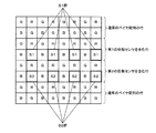
本実施形態におけるレンズ駆動部250は、例えばボイスコイルモーター(以下、VCM)である。また、撮像素子260は例えば図10に示すようにベイヤ配列の撮像部を持つ撮像素子であり、撮像部の一部に位相センサS1群およびS2群を含むように構成されている。位相センサS1群およびS2群の詳細については後述する。
The
処理部300はA/D変換部310及び320と、画像処理部330と、制御部340と、移動量算出部350と、レンズ制御部360を備えている。A/D変換部310は、撮像素子260から出力されるアナログの画像信号をデジタルの画像信号に変換して画像処理部330に出力する。画像処理部330は、A/D変換部310から出力された画像信号に対してホワイトバランス、補間処理(デモザイキング処理)、色変換、階調変換、ノイズリダクション等の画像処理を施し、表示部400に画像信号を出力する。表示部400は例えば液晶モニタであり、画像処理部330から出力される画像信号を表示する。
The
A/D変換部320は、撮像素子260の一部に設置された位相センサ領域S1およびS2から出力されるアナログの位相信号をデジタルの位相信号に変換して移動量算出部350に出力する。移動量算出部350はA/D変換部320から出力された位相信号から可動レンズ240の移動量を算出し、レンズ制御部360に出力する。移動量算出部350の詳細については後述する。
The A /
レンズ制御部360は、操作部600およびレンズ駆動部250と相互に接続されており、操作部600から出力される制御情報に従い、移動量算出部350から出力された移動量に基づいて可動レンズ240の位置を制御する。ここで可動レンズ240の位置xは例えば図9に示したように、対物レンズ230を構成する各レンズのうち、可動レンズに対して被写体側に隣接するレンズの後端を基準とした場合の、可動レンズの先端の位置として定義すればよい。操作部600およびレンズ制御部360の詳細については後述する。
The
制御部340は、白色光源110、画像処理部330、外部I/F部500と双方向に接続されており、外部I/F部500からの入力情報に従ってこれらを制御する。外部I/F部500は、内視鏡システムに対するユーザーからの入力等を行うためのインターフェースであり、撮影の開始/終了を行うためのスタートボタンや画像の明るさを調整するための露光量調整ボタン、その他の各種撮影条件や画像処理のパラメータを調整するための調整ボタンなどを含んで構成されている。
The
ここで図10に示した撮像素子260の一部に設置された位相センサS1群およびS2群と、出力される位相信号の詳細について説明する。本実施形態における位相センサS1群およびS2群を構成する各画素S1およびS2は、例えば特開2000-156823号公報の[0074]から[0083]にS1およびS2として記載された機能画素であり、それぞれが画素中心から左右に偏った開口部を持っている。これにより対物レンズ230の瞳を左右に分割した場合と同様の効果が得られるため、図10で水平方向に複数配置されたS1群からの像信号とS2群からの像信号をそれぞれの瞳を通った光線の位相信号とみなすことができる。例えば対物レンズ230で結像された被写体の像位置が撮像素子の撮像面に一致する(ピントが合っている)場合は、S1群からの位相信号とS2群からの位相信号は一致し、像位置が撮像面の前方または後方にある(ピントが合っていない)場合は、S1群からの位相信号とS2群からの位相信号に位相差が生じることになる。本実施形態において、位相センサS1群およびS2群はたとえば撮像部の中央に一組だけ設置してもよいし、必要に応じて撮像部の任意の場所に複数組設置してもよい
Here, the phase sensors S1 and S2 installed in a part of the
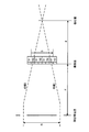
次に、移動量算出部350における可動レンズ240の移動量の算出方法について、図11を用いて説明する。図11は像位置が撮像面の後方に位置する場合の、分割された瞳を通る光線を示した図である。光線1はS1群に対応する瞳を通った光線であり、光線2はS2群に対応する瞳を通った光線である。ここでは像位置が撮像面とは異なる位置(後方)にあるため、S1群から出力される位相信号とS2群から出力される位相信号にはSの位相差が存在する。ここでSは正負の値を持つベクトルであり、図11に矢印で示した方向が正である。なお、位相差Sの算出には公知の位相差AFの技術を用いればよい。さらに撮像面から射出瞳位置までの距離をF、分割された瞳の重心間の距離をG、デフォーカス量をdとする。ここでdは正負の値を持つベクトルであり、図11に矢印で示した方向が正である。この時、下式(1)が成立するため、これを変形した下式(2)を用いてデフォーカス量dを算出することができる。なお、像位置が撮像面の前方にある場合も同様である。さらにここでは、例えば、前出の特開2000-156823号公報の[0108]か[0110]に記載された手法でデフォーカス量dを算出してもよい。
Next, a method of calculating the movement amount of the
G / ( F + d ) = S / d ・・・・・(1)
d = F・S / ( G - S ) ・・・・・(2)
G / (F + d) = S / d (1)
d = FS / (GS) (2)
本実施形態における移動量算出部350は、例えば画像信号と同じ周期で位相差センサS1群およびS2群から順次出力される位相信号に対して、上式(2)で算出したデフォーカス量dから合焦状態を実現するために必要な可動レンズ240の移動量を算出し、算出した移動量をレンズ制御部360に順次出力する。移動量の算出は、例えば予め対物レンズ230の設計データから、可動レンズ240の移動量と像位置の移動量の比Rを下式(3)で算出しておき、下式の(4)で移動量Dを算出すればよい。
For example, the movement
R = 可動レンズの移動量 / 像位置の移動量 ・・・・・(3)
D = -R・d ・・・・・(4)
R = Movement amount of movable lens / Movement amount of image position (3)
D = -R · d (4)
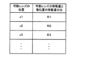
また、例えば可動レンズ240の位置xにより、可動レンズ240の移動量と像位置の移動量の比Rの値が変化する場合は、可動レンズの位置xnとこれに対応するRnの値を図12に示すようなLUT(ルックアップテーブル)として予め作成しておき、位相センサS1群およびS2群から位相信号が出力されたタイミングにおける可動レンズ240の位置xnに対応するRnを上式(4)のRとして使用することで移動量Dを算出することができる。
For example, when the value of the ratio R between the moving amount of the
さらに、例えば可動レンズ240の位置xにより図11に示した撮像面と射出瞳の距離Fや瞳の重心間の距離Gも変化する場合は、図13に示すように、可動レンズ240の位置xnに対応するFnおよびGnの値を加えたLUTを予め作成しておく。そして、まず位相センサS1群およびS2群から位相信号が出力されたタイミングにおける可動レンズ240の位置xnに対応するFnおよびGnの値を、上式(2)のFおよびGとして使用することでデフォーカス量dnを算出する。その後、算出したdnと可動レンズ240の位置xnに対応するRnを上式(4)のdとRとして使用することで移動量Dを算出することができる。なお、図13にテーブルで示したパラメータのうち、可動レンズ240の位置による変化が無視できるほど小さいものについては、考慮する必要がないことは言うまでもない。また、ここでは述べていない移動量を算出するためのパラメータについても、可動レンズ240の位置による変化が大きい場合は、前述の各パラメータ同様にLUTに追加して使用してもよい。
Further, for example, when the distance F between the imaging surface and the exit pupil shown in FIG. 11 and the distance G between the centers of gravity of the pupils change depending on the position x of the
ここで移動量算出部350は、例えば位相センサS1群およびS2群から順次出力される位相信号のすべてに対して移動量の算出及び出力を行ってもよいし、例えば任意の周期で位相信号をサンプリングしたうえで移動量の算出及び出力を行ってもよい。後者の場合、画像信号が出力されるよりも長い周期で、移動量算出部350から移動量が出力されることになる。
Here, the movement
次に操作部600、移動量算出部350、レンズ制御部360の詳細について説明する。図8に本実施形態における操作部600の一例を示す。本実施形態において、操作部600は例えば撮像部200と一体化して構成されており、ズームレバー610とAFボタン620を備えている。ズームレバー610は、例えば一定の範囲を連続的に動作させることが可能であり、ユーザーはズームレバー610を動かすことで、可動レンズ240の位置をWIDE端からTELE端まで連続的に調整することができる。具体的には、例えば操作部600は、ズームレバー610の位置情報をレンズ制御部360に出力する。レンズ制御部360は予め設定されたルックアップテーブル等を用いてズームレバー610の位置情報を可動レンズ240の位置情報に対応付け、可動レンズ240の位置情報をレンズ駆動部250に出力する。レンズ駆動部250は、レンズ制御部360から出力された位置情報に基づいて、可動レンズ240を駆動する。また、操作部600は例えばAFボタン620が押されるたびに、AFの開始/終了信号を交互にレンズ制御部360に出力する。
Next, details of the
図4に本実施形態におけるレンズ制御部360の一例を示す。レンズ制御部360は、観察モード判定部361と、レンズ位置決定部362を備えている。観察モード判定部361は、操作部600から出力されたAFの開始/終了情報に基づいて観察モードを決定し、レンズ位置決定部362に観察モード情報を出力する。具体的には、観察モード判定部361は操作部600からAFの開始信号が出力されていない場合には固定焦点モードを選択し、操作部600からAFの開始信号が出力された場合は、AFモードを選択する。レンズ位置決定部362は、観察モード判定部361で固定焦点モードが選択された場合は、前述のズームレバー610の位置情報に対応づけられた可動レンズ240の位置情報をレンズ駆動部250に出力する。レンズ駆動部250は、出力された位置情報に基づいて可動レンズ240の位置を調整する。
FIG. 4 shows an example of the
図7は本実施形態において固定焦点モードが選択された場合の、可動レンズ240の位置とそれに対応するベスト被写体距離、および被写界深度範囲を示している。なお本実施形態では、ズームレバー610を操作することで可動レンズ240の位置を連続的に移動させることが可能であるが、ここでは説明を分かりやすくするため段階的に移動させた場合を示している。本実施形態では固定焦点モードが選択された場合、ズームレバーの操作により従来のズーム機能を備えた内視鏡システムと同様のベスト被写体距離、および被写界深度を実現するように可動レンズ240の位置を制御している。
FIG. 7 shows the position of the
また、レンズ位置決定部362は、観察モード判定部361でAFモードが選択された場合、移動量算出部350から出力された移動量に基づいて可動レンズ240の移動後の位置情報を算出し、レンズ駆動部250に出力する。レンズ駆動部250は、出力された位置情報に基づいて可動レンズ240の位置を調整する。このような動作により、本実施形態ではAFモードが選択された場合、可動レンズの位置を調整することで被写体にピントを合わせることが可能になる。
In addition, when the AF mode is selected by the observation
レンズ位置決定部362は、例えば一度だけ合焦動作を行った時点でAF動作を終了してもよいし、観察モード判定部361からAFの終了信号が出力されるまではAF動作を継続してもよい。AF動作を継続したい場合、レンズ位置決定部362は移動量算出部350から周期的に出力される移動量に対応する可動レンズ240の位置情報を、レンズ駆動部250に順次出力すればよい。レンズ駆動部250は、レンズ位置決定部362から順次出力された位置情報に基づいて可動レンズ240の位置を調整する。このような動作を行うことで、本実施形態における内視鏡システムは、被写体距離が変動した場合も被写体に追従しながらピントを合わせ続けることが可能になる。これまでに述べたように、本実施形態における内視鏡システムは、1つの可動レンズでズーム機能とコンティニュアスAFを実現できるため、撮像部の小型化と低コスト化を実現することが可能になる。
For example, the lens
また、本実施形態では可動レンズ240の位置により画角も変化するため、画像信号と同じ周期で合焦動作を行った場合は画像がちらつき観察に支障をきたすことも予想される。この場合、前述のように移動量算出部350は任意の周期で位相信号をサンプリングし、サンプリング後の周期で移動量をレンズ位置決定部362に出力すればよい。これにより本実施形態における内視鏡システムは、任意の周期で合焦動作をおこなうことできるため、画像のちらつきを抑えながら被写体に追従してピントを合わせ続けることが可能になる。
In the present embodiment, since the angle of view also changes depending on the position of the
以上の本実施形態では、撮像装置は図1に示したように、画角と合焦被写体距離を同時に調整する可動レンズ240を含む撮像光学系と、撮像素子260と、複数の位相センサ(図10のS1、S2)と、当該複数の位相センサからの位相情報を取得する取得部(A/D変換部320に相当)と、可動レンズ240の位置を制御するレンズ制御部360と、取得部で取得された位相情報から求められる位相差に基づいて、合焦状態の実現に必要な可動レンズ240の移動量を算出する移動量算出部350とを含む。そして、レンズ制御部360は、移動量算出部350で算出された移動量に基づいて、可動レンズ240の位置を制御する。なお合焦状態とは、撮像光学系を通った光線による撮像素子260上の像についての合焦状態を指すものとする。
In the above embodiment, as shown in FIG. 1, the imaging apparatus includes an imaging optical system including the
ここで、本実施形態における撮像光学系は例えば図9に示すような構成であり、可動レンズ240を駆動することで、画角と合焦被写体距離を同時に調整する。ここで、可動レンズ240は1枚のレンズ、又は複数枚のレンズからなるレンズ群であることを想定しており、「画角と合焦被写体距離を同時に調整する」とは、当該可動レンズを動かすことで、画角と合焦被写体距離の両方が変動することを表す。なお、合焦被写体距離とは、撮像素子260において、撮像光学系を介した光が結像することによる被写体像が合焦状態にある場合の、撮像光学系からの被写体までの距離のことである。ただし、光が撮像素子260上において一点に収束しなかったとしても、その大きさが許容錯乱円よりも小さければ合焦状態にあると見なせることから、合焦被写体距離はある程度の幅を持つことになる。本実施形態における合焦被写体距離は、このような幅を持つ値であってもよいが、狭義にはベスト被写体距離であるものとし、ベスト被写体距離とは、撮像光学系を介した光が、撮像素子260上において収束する領域が最も小さい場合における、撮像光学系からの被写体までの距離を表すものとする。
Here, the imaging optical system in the present embodiment has a configuration as shown in FIG. 9, for example, and the
これにより、図9に示したようなレンズ構成(1群駆動レンズ)を用いた場合にも、合焦制御(AF、オートフォーカス)を適切に行うことが可能になる。AFにおいて広く用いられている手法であるコントラストAFでは、フォーカスを小刻みに変化させることで複数のコントラスト値を取得し、取得したコントラスト値の極大値を求める。しかし、1群駆動レンズを用いた場合、フォーカスの変化に伴い画角が変化してしまうため、取得画像にちらつきが生じてしまう。特に、継続的にAFを実行するコンティニュアスAFの場合にはちらつきによる影響が顕著である。そこで本実施形態では、位相センサからの位相情報を用いた合焦制御(位相差AF)を行うことで、取得画像でのちらつきを抑止する。 Accordingly, even when the lens configuration (the first group drive lens) as shown in FIG. 9 is used, it is possible to appropriately perform focusing control (AF, autofocus). In contrast AF, which is a widely used technique in AF, a plurality of contrast values are acquired by changing the focus in small increments, and a maximum value of the acquired contrast values is obtained. However, when the first group drive lens is used, the angle of view changes with a change in focus, and thus the acquired image flickers. In particular, in the case of continuous AF in which AF is continuously performed, the effect of flickering is significant. Therefore, in the present embodiment, flickering in the acquired image is suppressed by performing focusing control (phase difference AF) using phase information from the phase sensor.
また、移動量算出部350は、位相センサからの位相情報と、位相情報が取得されたタイミングにおける可動レンズ240の位置に基づいて、可動レンズ240の移動量を算出してもよい。
Further, the movement
これにより、位相情報だけでなく、当該位相情報が取得されたタイミングでの可動レンズ240の位置も考慮した移動量の算出処理が可能になる。位相情報に基づいた合焦制御とは、狭義には位相差AFのことであり、位相差AFでは瞳を分割して、分割したそれぞれの瞳からの像のずれを位相差として求める。ここで、瞳とは光学系の外から見た絞りの像のことであり、本実施形態では、このうち像側から見た瞳である射出瞳を主に考える。像側から見た場合、図11に示すように被写体からの光線は射出瞳の位置から照射されているように見えることになる。このように、瞳は光学的な条件に基づいて仮想的に設定されるものであるから、可動レンズ240の位置が変われば瞳の位置等も変わる可能性がある。よって、本実施形態での合焦制御を適切に行うためには、位相情報だけでなく、合焦動作時の光学的な状況、特に可動レンズ240の位置を用いるとよい。
As a result, not only the phase information but also the movement amount calculation process considering the position of the
また、移動量算出部350は、位相情報が取得されたタイミングにおける可動レンズ240の位置に基づいて、1つ以上のパラメータを変更してもよい。そして、変更されたパラメータと位相情報に基づいて、可動レンズ240の移動量を算出する。具体的には、パラメータとして、撮像素子260から瞳位置までの距離情報、分割された瞳の重心間距離情報、及び撮像素子260から像位置までの距離に対する移動量の比率情報の少なくとも1つを用いることが考えられる。
Further, the movement
これにより、可動レンズ240の位置に基づいてパラメータを変更し、当該パラメータを用いた移動量の算出が可能になる。ここで、パラメータとは位相情報から可動レンズ240の移動量Dを求める際に必要となるデータのことであり、特に可動レンズ240の位置に応じて数値が変化しうるものを指す。例えば本実施形態では、図11に示したように、位相センサ群S1で取得した像と位相センサ群S2で取得した像のずれを、位相差Sとして取得し、取得した位相差Sから可動レンズ240の移動量Dを求めることになる。その際、図11の例では、撮像面から射出瞳位置までの距離Fや、瞳の重心間距離Gを用いて撮像面から像位置までの距離dを求め、さらにdからDへ変換するために比率を表す値Rを取得しなくてはならない。ここで、F,G,Rは可動レンズ240の位置に応じて値が変化しうるものであるから、これらが本実施形態におけるパラメータとして用いることが考えられる。ここで、F,G,R等は可動レンズ240の位置xの関数として表されてもよいし、図13のようにルックアップテーブル等の形で保持されてもよい。また、ここで挙げたパラメータは一例であり、他のパラメータを用いて移動量を算出してもよい。
Thereby, a parameter is changed based on the position of the
また、撮像光学系は、可動レンズ240が広角端から望遠端に移動するに従って、画角及び合焦被写体距離が単調減少する光学系であってもよい。
The imaging optical system may be an optical system in which the angle of view and the in-focus subject distance monotonously decrease as the
これにより、図7に示したような撮像光学系を実現することが可能になる。つまり、可動レンズ240の位置を広角側から望遠側に移動させるほど、合焦被写体距離(ベスト被写体距離)は小さくなる。つまり、被写界深度範囲はより撮像光学系に近い位置に設定される(撮像光学系に近い位置に焦点が合う)ことになる。特に内視鏡装置等では、可動レンズ240を望遠側に移動させる(ズーム倍率を上げる)場合には、拡大観察を行うことが想定され、その場合には、挿入部(撮像部200)の先端も観察対象となる被写体に近づけることでさらに被写体を拡大することが一般的である。つまり、可動レンズ240を望遠側に移動させるほど、撮像光学系と被写体との距離が小さくなることが想定されるため、図7に示したような光学系を用いることで、ピントが合いやすくなるという利点がある。
This makes it possible to realize an imaging optical system as shown in FIG. That is, as the position of the
また、取得部は、撮像素子の画素配列の一部に設置された位相センサから位相情報を取得してもよい。 The acquisition unit may acquire phase information from a phase sensor installed in a part of the pixel array of the image sensor.
これにより、図10に示したような構成の撮像素子を用いることが可能になる。撮像素子とは別に位相センサを設けた場合、当該位相センサに対して被写体からの反射光を入射させるためのレンズが必要となる。そのため、撮像光学系の構成が複雑になり、小型化が難しくなる上、コストも高くなる。特に内視鏡装置では、撮像光学系が小型化できないと、生体に挿入する部分が大きくなってしまい好ましくない。よって、図10のような構成を用いることで、撮像光学系の小型化、低コスト化を図るとよい。 As a result, it is possible to use an imaging device having a configuration as shown in FIG. When a phase sensor is provided separately from the image sensor, a lens for making the reflected light from the subject incident on the phase sensor is necessary. This complicates the configuration of the imaging optical system, making it difficult to reduce the size and increasing the cost. Particularly in an endoscope apparatus, if the imaging optical system cannot be reduced in size, a portion to be inserted into a living body becomes large, which is not preferable. Therefore, it is preferable to reduce the size and cost of the imaging optical system by using the configuration shown in FIG.
また、レンズ制御部360は、取得部において撮像素子から画像情報が取得される周期と同じ周期で、可動レンズ240の位置を制御してもよい。或いは、取得部において撮像素子から画像情報が取得される周期よりも長い周期で、可動レンズ240の位置を制御してもよい。
In addition, the
これにより、可動レンズ240の位置の制御レートを、画像情報の取得レートと同等にすることも可能になるし、画像情報の取得レートよりも低くすることも可能になる。画像情報の取得タイミングと同じタイミングで位相情報を取得しているため、画像上の取得周期と同じ周期での可動レンズ240の位置制御は可能である。このようにした場合、高レートで合焦制御が行われることになるため、被写体に対してピントが合っている可能性を高くすることができる。一方、画像情報の取得レートが高い場合等では、同じレートで可動レンズ240の位置を制御しようとしても、レンズ駆動部250における機械的な制御が困難であることも考えられる。また、高レートの可動レンズ位置制御を行うと、可動レンズ240の位置が頻繁に変化する可能性があり、1群駆動レンズではちらつきの発生要因となる。その場合には、画像情報の取得周期よりも長い周期で可動レンズ240の位置を制御すればよい。こうすることで、画像情報によっては合焦制御が不十分な画像が生じる可能性はあるが、レンズ駆動部250での制御も容易になり、また取得した位相情報全てに対して処理を行う必要がないため、処理負荷を軽減することもできる。さらに、頻繁な可動レンズ240の移動を抑止できるため、画像のちらつきも低減できる。
Accordingly, the control rate of the position of the
また、レンズ制御部360は、可動レンズ240の位置の制御としてコンティニュアスAFを実行する制御を行ってもよい。
Further, the
これにより、AFとしてコンティニュアスAFを実行することが可能になる。動画像を取得するような場合(特に内視鏡装置であれば、効率的な生体内観察を行うために取得画像が動画像である可能性が高い)には、コンティニュアスAFによる継続的な合焦制御が効果的である。通常、1群駆動レンズが前提とした場合、コンティニュアスAFはちらつきによる影響が顕著となるため、実現が困難であるが、本実施形態の手法であれば、ちらつきの影響を抑止できるため、コンティニュアスAFを効果的に実現することができる。 Thereby, continuous AF can be executed as AF. When a moving image is acquired (especially in the case of an endoscopic device, the acquired image is likely to be a moving image for efficient in-vivo observation). Focus control is effective. Normally, when the first-group driving lens is assumed, continuous AF is difficult to realize because the influence of flicker becomes significant, but with the method of this embodiment, the influence of flicker can be suppressed. Continuous AF can be effectively realized.
また、可動レンズの移動範囲における広角端と望遠端の間の位置に基準点を設定した場合を考える。その際、レンズ制御部360は、可動レンズが当該基準点に対して望遠側に位置する場合に、移動量算出部350で算出された移動量に基づいて、可動レンズの位置を制御してもよい。
Consider a case where a reference point is set at a position between the wide-angle end and the telephoto end in the moving range of the movable lens. At this time, the
ここで、可動レンズ240が基準点に対して望遠側にある場合に、可動レンズ240の位置制御(つまり合焦制御・AF動作)を行うものとしたが、可動レンズ240が基準点に対して広角側にある場合には、AF動作は行ってもよいし、行わなくてもよい。ただし、可動レンズ240が広角側にある場合には、望遠側にある場合に比べて被写界深度が広く、ユーザーが手動でピント調整を行うことが可能であることが考えられるため、広角側ではAF動作は行わないものとして実装されてもよい。この場合、例えば観察モード判定部361が可動レンズ240の位置を取得するような構成とし、可動レンズ240が基準点よりも広角側にある場合にレンズ制御部360は固定焦点モードを選択し、可動レンズ240が基準点よりも望遠側にある場合にレンズ制御部360はAFモードを選択するといった制御を行えばよい。
Here, when the
これにより、可動レンズ240の位置に基づいて、合焦動作(AF動作)を行うか否かを決定することが可能になる。上述の例では、図8に示したAFボタン620を操作することでAF動作が開始されることになる。つまり、AF動作を行うか否かはユーザーが判断する必要があった。可動レンズ240の位置に基づいてAF動作を行うか否かを決定することができれば、ユーザーが自ら判断する必要がなく、またAF動作を実行する際にAFボタン620等を操作する必要もないため、ユーザーにとって使いやすいシステムを実現することができる。望遠側でAF動作を実行する理由としては、可動レンズ240が望遠側に行くほど(ズーム倍率が上がるほど)被写界深度が狭くなるため、手動でのピント合わせが困難になることが挙げられる。また、図7のようなレンズでは可動レンズ240が望遠側に行くほどベスト被写体距離が短くなる。ベスト被写体距離が短くなることでも被写界深度は狭くなるため、図7のようなレンズではさらに手動でのピント合わせが困難になり、AF動作を実行する利点が大きくなる。
This makes it possible to determine whether or not to perform a focusing operation (AF operation) based on the position of the
また、以上の本実施形態は、画角と合焦被写体距離を同時に調整する可動レンズ240を含む撮像光学系と、撮像素子260からの画像情報及び位相センサからの位相情報を取得する取得部(A/D変換部310及びA/D変換部320に相当)と、可動レンズ240の位置を制御するレンズ制御部360と、取得部で取得された位相情報に基づいて、可動レンズ240の移動量を算出する移動量算出部350とを含む内視鏡装置にも適用できる。そして、レンズ制御部360は、移動量算出部350で算出された移動量に基づいて、可動レンズ240の位置を制御する。
Further, in the present embodiment described above, the imaging optical system including the
これにより、撮像装置だけではなく、内視鏡装置においても本実施形態の処理を実行することが可能になる。内視鏡装置では、撮像部200を生体内に挿入するため、撮像部200を小型化することが好ましく、簡素な構成である1群駆動レンズ(図9)を用いる利点が大きい。その際、用途として病変部の発見・観察や、器具を用いた生体への処置が想定されることから、ユーザー(ドクター)に提示する画像にちらつき等が生じることは極力抑えなくてはならない。よって、本実施形態の手法を用いることで、撮像部200の小型化と、画像のちらつき等の抑止の両方が可能になり、ドクター及び被験者にとって好ましい内視鏡装置を実現することができる。
Thereby, it is possible to execute the processing of this embodiment not only in the imaging apparatus but also in the endoscope apparatus. In the endoscope apparatus, since the
3.第2の実施形態
本実施形態に係る撮像装置及びそれを含む内視鏡システムについて、図2を用いて説明する。
3. Second Embodiment An imaging apparatus according to this embodiment and an endoscope system including the imaging apparatus will be described with reference to FIG.
本実施形態における処理部300はA/D変換部310及び320と、画像処理部330と、制御部340と、移動量算出部350と、レンズ制御部360と、コントラスト値算出部370と、ボケ指標算出部380を備えている。A/D変換部310は、撮像素子260から出力されるアナログの画像信号をデジタルの画像信号に変換して画像処理部330とコントラスト値算出部370に出力する。コントラスト値算出部370は、例えばA/D変換部310から出力された画像信号の高周波成分を検出してコントラスト値を算出し、コントラスト値をレンズ制御部360に出力する。
In this embodiment, the
A/D変換部320は、撮像素子260の一部に設置された位相センサS1およびS2から出力されるアナログの位相信号をデジタルの位相信号に変換してボケ指標算出部380に出力する。ボケ指標算出部380は、例えばA/D変換部320から出力された位相信号の高周波成分を検出してボケ指標を算出し、ボケ指標をレンズ制御部360に出力する。ここでボケ指標とは、位相信号のボケ具合を表す指標であり、位相信号がボケて高周波成分が少なくなるほど小さな値となる。さらにボケ指標算出部380は、A/D変換部320から出力された位相信号をそのまま移動量算出部350に出力する。その他の部分については、第1の実施形態と同様である。
The A /
次に本実施形態におけるレンズ制御部360の詳細について、図5を用いて説明する。本実施形態におけるレンズ制御部360は、観察モード判定部361と、レンズ位置決定部362と、AFモード判定部363を備えている。観察モード判定部361は、操作部600から出力されたAFの開始/終了情報に基づいて観察モードを決定し、AFモード判定部363に観察モード情報を出力する。具体的には、観察モード判定部361は第1の実施形態と同様に、操作部600からAFの開始信号が出力されていない場合には固定焦点モードを選択し、操作部600からAFの開始信号が出力された場合は、AFモードを選択する。AFモード判定部363は、観察モード判定部361で固定焦点モードが選択された場合は固定焦点モードを選択し、そのままレンズ位置決定部362に出力する。またAFモード判定部363は、観察モード判定部361でAFモードが選択された場合は、ボケ指標算出部380から出力されるボケ指標を用いてAFモードを決定し、AFモード情報をレンズ位置決定部362に出力する。具体的には、AFモード判定部363は例えばボケ指標算出部380から出力されるボケ指標が閾値以下の場合はコントラストAFモードを選択し、閾値以上の場合は位相差AFモードを選択する。
Next, details of the
レンズ位置決定部362は、AFモード判定部363で固定焦点モードおよび位相差AFモードが選択された場合は、第1の実施形態の固定焦点モードおよびAFモードが選択された場合と同様の動作を行う。またレンズ位置決定部362は、AFモード判定部363でコントラストAFモードが選択された場合、まずコントラスト値算出部370から出力されるコントラスト値に基づいて、公知のコントラストAF技術と同様に可動レンズ240を制御することで合焦動作を行う。これは位相信号のボケ具合が大きい(ボケ指標が小さい)場合は位相差の算出が困難になるためであり、このような制御を行うことで、確実に被写体にピントを合わせることが可能になる。一度コントラストAFで被写体にピントを合わせた後は、ボケ指標算出部380で算出されるボケ指標が十分大きくなることでAFモード判定部363では位相差AFモードが選択されるため、レンズ位置決定部362は第1の実施形態のAFモードと同様の動作を行い、被写体に追従しながらピントを合わせ続けることが可能になる。これにより、本実施形態ではAF動作開始時もしくはAF動作中に画像が大きくボケた場合も、合焦動作を継続することが可能になる。
When the AF
以上の本実施形態では、撮像装置は図2に示したように、画像情報におけるコントラスト値を算出するコントラスト値算出部370を含む。そして、レンズ制御部360は、位相情報に基づいて可動レンズ240の位置を制御する位相モードと、コントラスト値に基づいて可動レンズ240の位置を制御するコントラストモードを切り替え可能に制御する。
In the above-described embodiment, the imaging apparatus includes the contrast
これにより、位相情報を用いた可動レンズ240の位置の制御(位相モードであり、狭義には位相差AF)と、コントラスト値を用いた可動レンズ240の位置の制御(コントラストモードであり、狭義にはコントラストAF)を切り替え可能に制御することが可能になる。つまり、状況に応じて位相モードを用いることもできるし、コントラストモードを用いることもできる。ただし、第1の実施形態で説明したとおり、1群駆動レンズを前提とした場合、コントラストモードは画像のちらつき等が生じるため好ましくない。よって、位相モードが効果的でない状況でコントラストモードを用い、そうでない場合は位相モードを用いることが考えられる。
Thus, control of the position of the
また、撮像装置は図2に示したように、画像情報により表される画像のボケの程度を表すボケ指標を算出するボケ指標算出部380を含んでもよい。そして、レンズ制御部360は、ボケ指標に基づいて、位相モードとコントラストモードを切り替える制御を行う。
In addition, as illustrated in FIG. 2, the imaging apparatus may include a blur
これにより、位相モードとコントラストモードをボケ指標に基づいて切り替えることが可能になる。位相モード(狭義には位相差AF)では、異なる射出瞳から射出された複数の像のずれ(狭義には位相差)を用いることが考えられる。つまり、位相モードが効果的でない状況として、具体的には前記複数の像が、ずれの判定が行えないほどにぼけてしまっているという状況が考えられる。位相センサでの位相信号の信号値が、ある位置では大きく、異なる位置では小さくなるといったように、信号の分布(信号波形)に特徴があれば、第1の射出瞳から射出された光による第1の像と、第2の射出瞳から射出された光による第2の像の空間的な位置ずれは容易に判別できる。しかし、ボケの程度が大きいと、信号値の上ピークと下ピークの差が小さくなり、平坦な信号波形になってしまう。平坦なもの同士を比較しても、どの程度の位置ずれが生じているかの判定は難しく、そのような状況では位相情報による合焦制御を行うことは困難である。よって、ボケ指標を用いることで、位相モードとコントラストモードを効果的に切り替えることが可能になる。狭義にはボケ指標によりボケの程度が大きいと判定されたときにはコントラストモードを用い、ボケの程度が小さいと判定されたときには位相モードを用いることが考えられる。 Thereby, the phase mode and the contrast mode can be switched based on the blur index. In the phase mode (in a narrow sense, phase difference AF), it is conceivable to use a shift (a phase difference in a narrow sense) between a plurality of images emitted from different exit pupils. That is, as a situation in which the phase mode is not effective, specifically, a situation in which the plurality of images are so blurred that determination of displacement cannot be performed. If there is a characteristic in the signal distribution (signal waveform) such that the signal value of the phase signal at the phase sensor is large at a certain position and small at a different position, the first signal generated by the light emitted from the first exit pupil is used. The spatial misalignment between the first image and the second image due to the light emitted from the second exit pupil can be easily determined. However, if the degree of blur is large, the difference between the upper peak and the lower peak of the signal value is reduced, resulting in a flat signal waveform. Even if flat objects are compared, it is difficult to determine how much the positional deviation has occurred. In such a situation, it is difficult to perform focus control based on phase information. Therefore, it is possible to effectively switch between the phase mode and the contrast mode by using the blur index. In a narrow sense, it is conceivable to use the contrast mode when it is determined that the degree of blur is large by the blur index, and to use the phase mode when it is determined that the degree of blur is small.
また、ボケ指標算出部380は、位相センサから出力される位相情報に基づいてボケ指標を算出してもよい。
Further, the blur
これにより、位相情報からボケ指標を算出することが可能になる。位相情報も被写体の像を表す信号を取得するものであるから、当該信号値に基づいてボケの程度を判定することは可能である。具体的には、上述したように信号波形が平坦であるか否かの判定を行えばよく、例えば位相情報の高周波成分を抽出し、当該高周波成分をボケ指標としてもよい。 Thereby, it is possible to calculate the blur index from the phase information. Since the phase information also obtains a signal representing the image of the subject, it is possible to determine the degree of blur based on the signal value. Specifically, it may be determined whether or not the signal waveform is flat as described above. For example, a high frequency component of phase information may be extracted and the high frequency component may be used as a blur index.
4.第3の実施形態
本実施形態に係る撮像装置及びそれを含む内視鏡システムについて、図3を用いて説明する。
4). Third Embodiment An imaging apparatus according to this embodiment and an endoscope system including the imaging apparatus will be described with reference to FIG.
本実施形態における処理部300はA/D変換部310及び320と、画像処理部330と、制御部340と、移動量算出部350と、レンズ制御部360と、コントラスト値算出部370を備えている。本実施形態においては、図3に示したように、コントラスト値算出部370がボケ指標算出部(図2におけるボケ指標算出部380に対応)を兼ねることになる。つまり、後述するようにボケ指標として位相情報ではなくコントラスト値を用いる点が第2の実施形態とは異なる。
The
A/D変換部310は、撮像素子260から出力されるアナログの画像信号をデジタルの画像信号に変換して画像処理部330とコントラスト値算出部370に出力する。コントラスト値算出部370は、例えばA/D変換部310から出力された画像信号の高周波成分を検出してコントラスト値を算出し、コントラスト値をレンズ制御部360に出力する。コントラスト値は、画像信号のボケ具合を表す指標であり、画像信号がボケて高周波成分が少なくなるほど小さな値となる。その他の部分については、第1の実施形態と同様である。
The A /
次に本実施形態におけるレンズ制御部360の詳細について、図6を用いて説明する。本実施形態におけるレンズ制御部360は、観察モード判定部361と、レンズ位置決定部362と、AFモード判定部363を備えている。観察モード判定部361は、操作部600から出力されたAFの開始/終了情報に基づいて観察モードを決定し、AFモード判定部363に観察モード情報を出力する。具体的には、観察モード判定部361は第1の実施形態と同様に、操作部600からAFの開始信号が出力されていない場合には固定焦点モードを選択し、操作部600からAFの開始信号が出力された場合は、AFモードを選択する。AFモード判定部363は、観察モード判定部361で固定焦点モードが選択された場合は固定焦点モードを選択し、そのままレンズ位置決定部362に出力する。またAFモード判定部363は、観察モード判定部361でAFモードが選択された場合は、コントラスト値算出部370から出力されるコントラスト値を用いてAFモードの内容(コントラストAFモードか、位相差AFモードか)を決定し、AFモード情報をレンズ位置決定部362に出力する。具体的には、AFモード判定部363は例えばコントラスト値算出部370から出力されるコントラスト値が閾値以下の場合はコントラストAFモードを選択し、閾値以上の場合は位相差AFモードを選択する。
Next, details of the
レンズ位置決定部362は、AFモード判定部363で固定焦点モードおよび位相差AFモードが選択された場合は、第1の実施形態の固定焦点モードおよびAFモードが選択された場合と同様の動作を行う。またレンズ位置決定部362は、AFモード判定部363でコントラストAFモードが選択された場合、まずコントラスト値算出部370から出力されるコントラスト値に基づいて、公知のコントラストAF技術と同様に可動レンズ240を制御することで合焦動作を行う。これは、位相信号のボケ具合が大きい場合は位相差の算出が困難になるためであり、このような制御を行うことで、確実に被写体にピントを合わせることが可能になる。なお、コントラスト値は位相信号のボケ具合と相関を持つため、本実施形態ではコントラスト値により位相信号のボケ具合を判断している。一度コントラストAFで被写体にピントを合わせた後は、コントラスト値が十分大きくなることでAFモード判定部363では位相差AFモードが選択されるため、レンズ位置決定部362は第1の実施形態のAFモードと同様の動作を行い、被写体に追従しながらピントを合わせ続けることが可能になる。これにより、本実施形態ではAF動作開始時もしくはAF動作中に画像が大きくボケた場合も、合焦動作を継続することが可能になる。
When the AF
以上の本実施形態では、ボケ指標算出部(本実施形態においては図3に示すようにコントラスト値算出部370がボケ指標算出部の処理を行うことになる)は、コントラスト値算出部370で算出されるコントラスト値に基づいてボケ指標を算出する。
In the present embodiment described above, the blur index calculation unit (in this embodiment, the contrast
これにより、コントラスト値からボケ指標を算出することが可能になる。コントラスト値は例えば画像の高周波成分等から求められるものであり、合焦の度合いの判定にも用いることができるのであるから、コントラスト値からボケの程度を求めることが可能である。具体的には、コントラスト値をそのままボケ指標として用いてもよい。 Thereby, it is possible to calculate the blur index from the contrast value. The contrast value is obtained from, for example, a high-frequency component of the image and can be used to determine the degree of focusing. Therefore, the degree of blur can be obtained from the contrast value. Specifically, the contrast value may be used as it is as a blur index.
以上、本発明を適用した3つの実施の形態1〜3およびその変形例について説明したが、本発明は、各実施の形態1〜3やその変形例そのままに限定されるものではなく、実施段階では、発明の要旨を逸脱しない範囲内で構成要素を変形して具体化することができる。また、上記した各実施の形態1〜3や変形例に開示されている複数の構成要素を適宜組み合わせることによって、種々の発明を形成することができる。例えば、各実施の形態1〜3や変形例に記載した全構成要素からいくつかの構成要素を削除してもよい。さらに、異なる実施の形態や変形例で説明した構成要素を適宜組み合わせてもよい。また、明細書又は図面において、少なくとも一度、より広義または同義な異なる用語と共に記載された用語は、明細書又は図面のいかなる箇所においても、その異なる用語に置き換えることができる。このように、発明の主旨を逸脱しない範囲内において種々の変形や応用が可能である。
The three
100 光源部、110 白色光源、120 集光レンズ、200 撮像部、
210 ライトガイドファイバ、220 照明レンズ、230 対物レンズ、
240 可動レンズ、250 レンズ駆動部、260 撮像素子、300 処理部、
310,320 A/D変換部、330 画像処理部、340 制御部、
350 移動量算出部、360 レンズ制御部、361 観察モード判定部、
362 レンズ位置決定部、363 モード判定部、370 コントラスト値算出部、
380 ボケ指標算出部、400 表示部、500 外部I/F部、600 操作部、
610 ズームレバー、620 AFボタン
100 light source unit, 110 white light source, 120 condenser lens, 200 imaging unit,
210 light guide fiber, 220 illumination lens, 230 objective lens,
240 movable lens, 250 lens driving unit, 260 imaging device, 300 processing unit,
310, 320 A / D conversion unit, 330 image processing unit, 340 control unit,
350 movement amount calculation unit, 360 lens control unit, 361 observation mode determination unit,
362 lens position determination unit, 363 mode determination unit, 370 contrast value calculation unit,
380 blur index calculation unit, 400 display unit, 500 external I / F unit, 600 operation unit,
610 Zoom lever, 620 AF button
Claims (13)
撮像素子と、
複数の位相センサと、
前記複数の位相センサからの位相情報を取得する取得部と、
前記可動レンズの位置を制御するレンズ制御部と、
前記取得部で取得された前記位相情報に基づく位相差に基づいて、前記撮像光学系を通った光線による前記撮像素子上の像の合焦状態を実現するために必要な前記可動レンズの移動量を算出する移動量算出部と、
を含み、
前記撮像光学系は、前記可動レンズが広角端から望遠端に移動するに従って、前記画角及び前記合焦被写体距離が単調減少する光学系であり、
前記移動量算出部は、
前記可動レンズの位置に基づいて、前記可動レンズの前記移動量を求める1つ以上のパラメータを変更し、変更された前記パラメータと前記位相情報に基づいて、前記可動レンズの前記移動量を算出し、
前記レンズ制御部は、
前記移動量算出部で算出された前記移動量に基づいて、前記可動レンズの位置を制御することを特徴とする撮像装置。 An imaging optical system including a movable lens composed of one lens group in which the in-focus subject distance is changed in accordance with the change in the angle of view;
An image sensor;
A plurality of phase sensors;
An acquisition unit for acquiring phase information from the plurality of phase sensors;
A lens control unit for controlling the position of the movable lens;
Based on the phase difference based on the phase information acquired by the acquisition unit, the amount of movement of the movable lens necessary for realizing the focused state of the image on the image sensor by the light beam that has passed through the imaging optical system A movement amount calculation unit for calculating
Including
The imaging optical system is an optical system in which the angle of view and the in-focus subject distance monotonously decrease as the movable lens moves from the wide-angle end to the telephoto end.
The movement amount calculation unit
One or more parameters for obtaining the amount of movement of the movable lens are changed based on the position of the movable lens, and the amount of movement of the movable lens is calculated based on the changed parameter and the phase information. ,
The lens control unit
An image pickup apparatus that controls the position of the movable lens based on the movement amount calculated by the movement amount calculation unit.
前記移動量算出部は、
前記位相センサからの前記位相情報と、前記位相情報が取得されたタイミングにおける前記可動レンズの位置に基づいて、前記可動レンズの前記移動量を算出することを特徴とする撮像装置。 In claim 1,
The movement amount calculation unit
An imaging apparatus, wherein the amount of movement of the movable lens is calculated based on the phase information from the phase sensor and a position of the movable lens at a timing when the phase information is acquired.
前記移動量算出部は、
前記パラメータとして、前記撮像素子から瞳位置までの距離情報、分割された瞳の重心間距離情報、及び前記撮像素子から像位置までの距離に対する前記移動量の比率情報の少なくとも1つを変更し、変更された前記パラメータと前記位相情報に基づいて、前記可動レンズの前記移動量を算出することを特徴とする撮像装置。 In claim 1,
The movement amount calculation unit
As the parameter, at least one of the distance information from the image sensor to the pupil position, the distance information between the centers of gravity of the divided pupils, and the ratio information of the movement amount with respect to the distance from the image sensor to the image position is changed, An imaging apparatus, wherein the moving amount of the movable lens is calculated based on the changed parameter and the phase information.
画像情報におけるコントラスト値を算出するコントラスト値算出部を含み、
前記レンズ制御部は、
前記位相情報に基づいて前記可動レンズの位置を制御する位相モードと、前記コントラスト値に基づいて前記可動レンズの位置を制御するコントラストモードを切り替える制御を行うことを特徴とする撮像装置。 In claim 1,
A contrast value calculation unit for calculating a contrast value in the image information;
The lens control unit
An imaging apparatus that performs control to switch between a phase mode for controlling the position of the movable lens based on the phase information and a contrast mode for controlling the position of the movable lens based on the contrast value.
前記画像情報により表される画像のボケの程度を表すボケ指標を算出するボケ指標算出部を含み、
前記レンズ制御部は、
前記ボケ指標に基づいて、前記位相モードと前記コントラストモードを切り替える制御を行うことを特徴とする撮像装置。 In claim 4,
A blur index calculation unit that calculates a blur index that represents the degree of blur of the image represented by the image information;
The lens control unit
An image pickup apparatus that performs control to switch between the phase mode and the contrast mode based on the blur index.
前記ボケ指標算出部は、
前記位相センサから出力される前記位相情報に基づいて前記ボケ指標を算出することを特徴とする撮像装置。 In claim 5,
The blur index calculation unit
An image pickup apparatus that calculates the blur index based on the phase information output from the phase sensor.
前記ボケ指標算出部は、
前記コントラスト値算出部で算出される前記コントラスト値に基づいて前記ボケ指標を算出することを特徴とする撮像装置。 In claim 5,
The blur index calculation unit
An imaging apparatus, wherein the blur index is calculated based on the contrast value calculated by the contrast value calculation unit.
前記取得部は、
前記撮像素子の画素配列の一部に設置された前記位相センサから前記位相情報を取得することを特徴とする撮像装置。 In claim 1,
The acquisition unit
The imaging apparatus, wherein the phase information is acquired from the phase sensor installed in a part of a pixel array of the imaging element.
前記レンズ制御部は、
前記取得部において前記撮像素子から画像情報が取得される周期と同じ周期で、前記可動レンズの位置を制御することを特徴とする撮像装置。 In claim 1,
The lens control unit
An image pickup apparatus, wherein the position of the movable lens is controlled at the same cycle as the cycle in which image information is obtained from the image sensor in the acquisition unit.
前記レンズ制御部は、
前記取得部において前記撮像素子から画像情報が取得される周期よりも長い周期で、前記可動レンズの位置を制御することを特徴とする撮像装置。 In claim 1,
The lens control unit
An image pickup apparatus, wherein the position of the movable lens is controlled in a period longer than a period in which image information is acquired from the image sensor in the acquisition unit.
前記レンズ制御部は、
前記可動レンズの位置の制御としてコンティニュアスAF(AutoFocus)を実行する制御を行うことを特徴とする撮像装置。 In claim 1,
The lens control unit
An image pickup apparatus that performs control for executing continuous AF (AutoFocus) as control of the position of the movable lens.
前記レンズ制御部は、
広角端と望遠端の間に位置する基準点に対して、前記可動レンズが望遠側に位置する場合に、前記移動量算出部で算出された前記移動量に基づいて、前記可動レンズの位置を制御することを特徴とする撮像装置。 In claim 1,
The lens control unit
When the movable lens is located on the telephoto side with respect to a reference point located between the wide-angle end and the telephoto end, the position of the movable lens is determined based on the movement amount calculated by the movement amount calculation unit. An imaging device characterized by controlling.
撮像素子と、
複数の位相センサと、
前記複数の位相センサからの位相情報を取得する取得部と、
前記可動レンズの位置を制御するレンズ制御部と、
前記取得部で取得された前記位相情報に基づく位相差に基づいて、前記撮像光学系を通った光線による前記撮像素子上の像の合焦状態を実現するために必要な前記可動レンズの移動量を算出する移動量算出部と、
を含み、
前記撮像光学系は、前記可動レンズが広角端から望遠端に移動するに従って、前記画角及び前記合焦被写体距離が単調減少する光学系であり、
前記移動量算出部は、
前記可動レンズの位置に基づいて、前記可動レンズの前記移動量を求める1つ以上のパラメータを変更し、変更された前記パラメータと前記位相情報に基づいて、前記可動レンズの前記移動量を算出し、
前記レンズ制御部は、
前記移動量算出部で算出された前記移動量に基づいて、前記可動レンズの位置を制御することを特徴とする内視鏡装置。 An imaging optical system including a movable lens composed of one lens group in which the in-focus subject distance is changed in accordance with the change in the angle of view;
An image sensor;
A plurality of phase sensors;
An acquisition unit for acquiring phase information from the plurality of phase sensors;
A lens control unit for controlling the position of the movable lens;
Based on the phase difference based on the phase information acquired by the acquisition unit, the amount of movement of the movable lens necessary for realizing the focused state of the image on the image sensor by the light beam that has passed through the imaging optical system A movement amount calculation unit for calculating
Including
The imaging optical system is an optical system in which the angle of view and the in-focus subject distance monotonously decrease as the movable lens moves from the wide-angle end to the telephoto end.
The movement amount calculation unit
One or more parameters for obtaining the amount of movement of the movable lens are changed based on the position of the movable lens, and the amount of movement of the movable lens is calculated based on the changed parameter and the phase information. ,
The lens control unit
An endoscope apparatus, wherein the position of the movable lens is controlled based on the movement amount calculated by the movement amount calculation unit.
Priority Applications (5)
| Application Number | Priority Date | Filing Date | Title |
|---|---|---|---|
| JP2011231947A JP5973708B2 (en) | 2011-10-21 | 2011-10-21 | Imaging apparatus and endoscope apparatus |
| EP12842285.4A EP2770359A4 (en) | 2011-10-21 | 2012-10-10 | Imaging device, endoscope device, and method for controlling imaging device |
| CN201280051353.3A CN103907042A (en) | 2011-10-21 | 2012-10-10 | Imaging device, endoscope device, and method for controlling imaging device |
| PCT/JP2012/076172 WO2013058145A1 (en) | 2011-10-21 | 2012-10-10 | Imaging device, endoscope device, and method for controlling imaging device |
| US14/229,168 US10129454B2 (en) | 2011-10-21 | 2014-03-28 | Imaging device, endoscope apparatus, and method for controlling imaging device |
Applications Claiming Priority (1)
| Application Number | Priority Date | Filing Date | Title |
|---|---|---|---|
| JP2011231947A JP5973708B2 (en) | 2011-10-21 | 2011-10-21 | Imaging apparatus and endoscope apparatus |
Publications (3)
| Publication Number | Publication Date |
|---|---|
| JP2013088766A JP2013088766A (en) | 2013-05-13 |
| JP2013088766A5 JP2013088766A5 (en) | 2014-11-20 |
| JP5973708B2 true JP5973708B2 (en) | 2016-08-23 |
Family
ID=48140793
Family Applications (1)
| Application Number | Title | Priority Date | Filing Date |
|---|---|---|---|
| JP2011231947A Active JP5973708B2 (en) | 2011-10-21 | 2011-10-21 | Imaging apparatus and endoscope apparatus |
Country Status (5)
| Country | Link |
|---|---|
| US (1) | US10129454B2 (en) |
| EP (1) | EP2770359A4 (en) |
| JP (1) | JP5973708B2 (en) |
| CN (1) | CN103907042A (en) |
| WO (1) | WO2013058145A1 (en) |
Families Citing this family (19)
| Publication number | Priority date | Publication date | Assignee | Title |
|---|---|---|---|---|
| JP6103849B2 (en) * | 2012-08-02 | 2017-03-29 | オリンパス株式会社 | Endoscope apparatus and method for operating endoscope apparatus |
| WO2014208224A1 (en) * | 2013-06-24 | 2014-12-31 | オリンパスメディカルシステムズ株式会社 | Autofocus device |
| WO2015064462A1 (en) * | 2013-10-31 | 2015-05-07 | オリンパスメディカルシステムズ株式会社 | Imaging system and imaging system operation method |
| EP3123919B1 (en) * | 2014-03-28 | 2019-07-10 | FUJIFILM Corporation | Endoscope apparatus |
| JP6218709B2 (en) * | 2014-09-05 | 2017-10-25 | 富士フイルム株式会社 | Endoscope system, processor device, operation method of endoscope system, and operation method of processor device |
| CN107005646B (en) * | 2014-12-02 | 2020-05-19 | 奥林巴斯株式会社 | Focus control device, endoscope device, and control method for focus control device |
| WO2016208664A1 (en) * | 2015-06-25 | 2016-12-29 | オリンパス株式会社 | Endoscope device |
| JPWO2017094122A1 (en) * | 2015-12-01 | 2018-11-01 | オリンパス株式会社 | Imaging apparatus, endoscope apparatus, and imaging method |
| JP6670853B2 (en) | 2016-01-15 | 2020-03-25 | オリンパス株式会社 | Focus control device, endoscope device, and method of operating focus control device |
| JP6670854B2 (en) * | 2016-01-15 | 2020-03-25 | オリンパス株式会社 | Focus control device, endoscope device, and method of operating focus control device |
| WO2018029962A1 (en) | 2016-08-08 | 2018-02-15 | ソニー株式会社 | Endoscope device and method for controlling endoscope device |
| CN106371374A (en) * | 2016-11-07 | 2017-02-01 | 福州幻科机电科技有限公司 | Intelligent control circuit system for minimally invasive endoscopic four-freedom-degree locator |
| CN108540711A (en) * | 2017-03-03 | 2018-09-14 | 上海传英信息技术有限公司 | Mobile terminal and its image pickup method |
| JP6956197B2 (en) * | 2017-11-10 | 2021-11-02 | 富士フイルム株式会社 | Endoscopic system and how to operate it |
| US11070745B2 (en) * | 2019-10-28 | 2021-07-20 | Karl Storz Imaging, Inc. | Automatic image orientation based on use |
| CN112263388A (en) * | 2020-10-14 | 2021-01-26 | 深圳市乐升科技有限公司 | Ear picking device control method and system |
| WO2022176469A1 (en) * | 2021-02-19 | 2022-08-25 | 富士フイルム株式会社 | Focus control device, lens device, and imaging apparatus |
| CN115024679A (en) * | 2022-04-14 | 2022-09-09 | 中山大学孙逸仙纪念医院 | Visual trachea cannula endoscope guide wire structure and management method of intelligent module thereof |
| CN114827462B (en) * | 2022-04-15 | 2024-04-16 | 深圳市道通智能航空技术股份有限公司 | Focusing method, focusing device, electronic equipment and unmanned aerial vehicle |
Family Cites Families (27)
| Publication number | Priority date | Publication date | Assignee | Title |
|---|---|---|---|---|
| JPS5590928A (en) * | 1978-12-29 | 1980-07-10 | Olympus Optical Co Ltd | Endoscope objective lens which performs changing of magnification and focusing simultaneously |
| JPH0743603A (en) * | 1993-07-30 | 1995-02-14 | Canon Inc | Automatic focusing camera |
| JP3726399B2 (en) | 1997-02-28 | 2005-12-14 | ソニー株式会社 | Autofocus device for video camera |
| JP3592147B2 (en) | 1998-08-20 | 2004-11-24 | キヤノン株式会社 | Solid-state imaging device |
| JP2001324662A (en) * | 2000-05-16 | 2001-11-22 | Ricoh Co Ltd | Lens interlocking mechanism |
| JP3980284B2 (en) | 2001-03-02 | 2007-09-26 | ペンタックス株式会社 | Endoscope device |
| JP4338331B2 (en) | 2001-03-02 | 2009-10-07 | Hoya株式会社 | Endoscope device |
| JP2002369795A (en) * | 2001-06-15 | 2002-12-24 | Pentax Corp | Electronic endoscopic equipment |
| JP3797543B2 (en) * | 2001-10-26 | 2006-07-19 | 富士写真フイルム株式会社 | Automatic focus adjustment device |
| JP2004294788A (en) | 2003-03-27 | 2004-10-21 | Fuji Photo Optical Co Ltd | Electronic endoscope device provided with automatic focusing function |
| JP2005221731A (en) * | 2004-02-05 | 2005-08-18 | Konica Minolta Photo Imaging Inc | Imaging device |
| JP2006091252A (en) * | 2004-09-22 | 2006-04-06 | Canon Software Inc | Imaging apparatus, imaging method and program |
| JP4349407B2 (en) | 2006-11-17 | 2009-10-21 | ソニー株式会社 | Imaging device |
| JP4746110B2 (en) * | 2007-02-15 | 2011-08-10 | パナソニック株式会社 | Imaging device and camera body |
| JP5098405B2 (en) * | 2007-04-11 | 2012-12-12 | 株式会社ニコン | Imaging device, focus detection device, and imaging device |
| US8525917B2 (en) * | 2007-08-06 | 2013-09-03 | Canon Kabushiki Kaisha | Image sensing apparatus with plural focus detection pixel groups |
| JP5264131B2 (en) * | 2007-09-14 | 2013-08-14 | キヤノン株式会社 | Imaging device |
| JP2009115893A (en) * | 2007-11-02 | 2009-05-28 | Canon Inc | Image-pickup apparatus |
| US8488046B2 (en) * | 2007-12-27 | 2013-07-16 | Digitaloptics Corporation | Configurable tele wide module |
| JP5241355B2 (en) * | 2008-07-10 | 2013-07-17 | キヤノン株式会社 | Imaging apparatus and control method thereof |
| JP4760894B2 (en) * | 2008-11-04 | 2011-08-31 | ソニー株式会社 | Imaging device |
| JP5543098B2 (en) * | 2008-11-14 | 2014-07-09 | キヤノン株式会社 | Imaging device |
| JP5253207B2 (en) * | 2009-02-02 | 2013-07-31 | キヤノン株式会社 | Imaging apparatus and control method thereof |
| JP2010252277A (en) * | 2009-04-20 | 2010-11-04 | Panasonic Corp | Solid-state imaging apparatus, and electronic camera |
| JP5415208B2 (en) * | 2009-09-30 | 2014-02-12 | 富士フイルム株式会社 | Imaging device |
| JP2011133815A (en) * | 2009-12-25 | 2011-07-07 | Sony Corp | Lens barrel and imaging apparatus |
| JP5750550B2 (en) * | 2012-09-06 | 2015-07-22 | 富士フイルム株式会社 | Imaging apparatus and focus control method |
-
2011
- 2011-10-21 JP JP2011231947A patent/JP5973708B2/en active Active
-
2012
- 2012-10-10 CN CN201280051353.3A patent/CN103907042A/en active Pending
- 2012-10-10 EP EP12842285.4A patent/EP2770359A4/en not_active Withdrawn
- 2012-10-10 WO PCT/JP2012/076172 patent/WO2013058145A1/en active Application Filing
-
2014
- 2014-03-28 US US14/229,168 patent/US10129454B2/en active Active
Also Published As
| Publication number | Publication date |
|---|---|
| EP2770359A4 (en) | 2015-07-22 |
| US20140210974A1 (en) | 2014-07-31 |
| WO2013058145A1 (en) | 2013-04-25 |
| EP2770359A1 (en) | 2014-08-27 |
| CN103907042A (en) | 2014-07-02 |
| JP2013088766A (en) | 2013-05-13 |
| US10129454B2 (en) | 2018-11-13 |
Similar Documents
| Publication | Publication Date | Title |
|---|---|---|
| JP5973708B2 (en) | Imaging apparatus and endoscope apparatus | |
| JP5948076B2 (en) | Focus control device, endoscope device and focus control method | |
| JP5415973B2 (en) | IMAGING DEVICE, ENDOSCOPE SYSTEM, AND OPERATION METHOD OF IMAGING DEVICE | |
| JP5953187B2 (en) | Focus control device, endoscope system, and focus control method | |
| JP6013020B2 (en) | Endoscope apparatus and method for operating endoscope apparatus | |
| JP6103849B2 (en) | Endoscope apparatus and method for operating endoscope apparatus | |
| JP5951211B2 (en) | Focus control device and endoscope device | |
| WO2015044996A1 (en) | Endoscope device and method for controlling endoscope device | |
| JP5698476B2 (en) | ENDOSCOPE SYSTEM, ENDOSCOPE SYSTEM OPERATING METHOD, AND IMAGING DEVICE | |
| JP2012125293A (en) | Control device, endoscope apparatus and focus control method | |
| JP2012095828A (en) | Imaging apparatus, endoscope apparatus, and image generation method | |
| JP6124655B2 (en) | IMAGING DEVICE, IMAGING DEVICE CONTROL METHOD, AND PROGRAM | |
| JP5996218B2 (en) | Endoscope apparatus and method for operating endoscope apparatus | |
| JPWO2015064462A1 (en) | ENDOSCOPE IMAGING SYSTEM AND ENDOSCOPE IMAGING SYSTEM OPERATING METHOD | |
| JP2007286613A (en) | Endoscopic apparatus | |
| JP6120491B2 (en) | Endoscope apparatus and focus control method for endoscope apparatus | |
| JP6177387B2 (en) | Endoscope device focus control device, endoscope device, and operation method of endoscope control device | |
| WO2013061939A1 (en) | Endoscopic device and focus control method | |
| US10917555B2 (en) | Imaging apparatus, focus control method, and focus determination method | |
| JP2004138884A (en) | Method for automatically focusing endoscope | |
| WO2022014366A1 (en) | Endoscope system, endoscope control method, and program |
Legal Events
| Date | Code | Title | Description |
|---|---|---|---|
| A521 | Request for written amendment filed |
Free format text: JAPANESE INTERMEDIATE CODE: A523 Effective date: 20141001 |
|
| A621 | Written request for application examination |
Free format text: JAPANESE INTERMEDIATE CODE: A621 Effective date: 20141001 |
|
| A131 | Notification of reasons for refusal |
Free format text: JAPANESE INTERMEDIATE CODE: A131 Effective date: 20150929 |
|
| A521 | Request for written amendment filed |
Free format text: JAPANESE INTERMEDIATE CODE: A523 Effective date: 20151120 |
|
| A131 | Notification of reasons for refusal |
Free format text: JAPANESE INTERMEDIATE CODE: A131 Effective date: 20160405 |
|
| A521 | Request for written amendment filed |
Free format text: JAPANESE INTERMEDIATE CODE: A523 Effective date: 20160524 |
|
| TRDD | Decision of grant or rejection written | ||
| A01 | Written decision to grant a patent or to grant a registration (utility model) |
Free format text: JAPANESE INTERMEDIATE CODE: A01 Effective date: 20160705 |
|
| A61 | First payment of annual fees (during grant procedure) |
Free format text: JAPANESE INTERMEDIATE CODE: A61 Effective date: 20160715 |
|
| R151 | Written notification of patent or utility model registration |
Ref document number: 5973708 Country of ref document: JP Free format text: JAPANESE INTERMEDIATE CODE: R151 |
|
| R250 | Receipt of annual fees |
Free format text: JAPANESE INTERMEDIATE CODE: R250 |
|
| R250 | Receipt of annual fees |
Free format text: JAPANESE INTERMEDIATE CODE: R250 |
|
| R250 | Receipt of annual fees |
Free format text: JAPANESE INTERMEDIATE CODE: R250 |
|
| R250 | Receipt of annual fees |
Free format text: JAPANESE INTERMEDIATE CODE: R250 |
|
| R250 | Receipt of annual fees |
Free format text: JAPANESE INTERMEDIATE CODE: R250 |