WO2015044985A1 - 液受けユニットおよび回転電機 - Google Patents
液受けユニットおよび回転電機 Download PDFInfo
- Publication number
- WO2015044985A1 WO2015044985A1 PCT/JP2013/005813 JP2013005813W WO2015044985A1 WO 2015044985 A1 WO2015044985 A1 WO 2015044985A1 JP 2013005813 W JP2013005813 W JP 2013005813W WO 2015044985 A1 WO2015044985 A1 WO 2015044985A1
- Authority
- WO
- WIPO (PCT)
- Prior art keywords
- liquid
- rotating electrical
- electrical machine
- heat exchanger
- side portion
- Prior art date
- Legal status (The legal status is an assumption and is not a legal conclusion. Google has not performed a legal analysis and makes no representation as to the accuracy of the status listed.)
- Ceased
Links
Images

Classifications
-
- H—ELECTRICITY
- H02—GENERATION; CONVERSION OR DISTRIBUTION OF ELECTRIC POWER
- H02K—DYNAMO-ELECTRIC MACHINES
- H02K5/00—Casings; Enclosures; Supports
- H02K5/04—Casings or enclosures characterised by the shape, form or construction thereof
- H02K5/10—Casings or enclosures characterised by the shape, form or construction thereof with arrangements for protection from ingress, e.g. water or fingers
-
- F—MECHANICAL ENGINEERING; LIGHTING; HEATING; WEAPONS; BLASTING
- F24—HEATING; RANGES; VENTILATING
- F24F—AIR-CONDITIONING; AIR-HUMIDIFICATION; VENTILATION; USE OF AIR CURRENTS FOR SCREENING
- F24F13/00—Details common to, or for air-conditioning, air-humidification, ventilation or use of air currents for screening
- F24F13/22—Means for preventing condensation or evacuating condensate
-
- H—ELECTRICITY
- H02—GENERATION; CONVERSION OR DISTRIBUTION OF ELECTRIC POWER
- H02K—DYNAMO-ELECTRIC MACHINES
- H02K9/00—Arrangements for cooling or ventilating
- H02K9/10—Arrangements for cooling or ventilating by gaseous cooling medium flowing in closed circuit, a part of which is external to the machine casing
- H02K9/12—Arrangements for cooling or ventilating by gaseous cooling medium flowing in closed circuit, a part of which is external to the machine casing wherein the cooling medium circulates freely within the casing
-
- H—ELECTRICITY
- H02—GENERATION; CONVERSION OR DISTRIBUTION OF ELECTRIC POWER
- H02K—DYNAMO-ELECTRIC MACHINES
- H02K9/00—Arrangements for cooling or ventilating
- H02K9/24—Protection against failure of cooling arrangements, e.g. due to loss of cooling medium or due to interruption of the circulation of cooling medium
Definitions
- Embodiments of the present invention relate to a liquid receiving unit and a rotating electrical machine using the same.
- cooling gas circulates in the casing.
- the cooling gas is cooled by an external coolant in the heat exchanger.
- the coolant is usually water.
- the coolant when the coolant leaks in the heat exchanger, or the liquid such as the condensate when the moisture in the cooling gas is condensed in the heat exchanger is fixed to the rotor of the rotating electrical machine. If the rotating electrical machine main body such as a child is touched, there is a possibility that the insulation performance is deteriorated or a short circuit accident occurs. For this reason, as shown in Patent Document 1, a liquid receiving portion that receives and transfers the liquid that has dropped to the lower side of the heat exchanger is provided to protect the rotating electrical machine main body.
- the liquid receiving portion has a holding and transferring portion that holds and transfers the liquid, and a flat plate portion that receives the liquid in an inclined flat plate shape and drops it onto the holding and transferring portion.
- an object of the embodiment of the present invention is to provide a liquid receiver that reliably captures a leaked liquid when a cooling gas flows from the top to the bottom in the rotating electric machine.
- the rotating electrical machine is provided with a hermetically sealed container, a rotor that is rotatably supported, and an outer periphery of the rotor that is spaced from the rotor.
- a rotating electrical machine body having a stator and disposed in the sealed container; and heat in the sealed container that cools a cooling gas for cooling the rotating electrical machine body by a coolant supplied from outside An exchanger, a fan that circulates the cooling gas in the sealed container, and disposed below the heat exchanger and above the rotating electrical machine main body, and has a small flow gradient in the longitudinal direction.
- a plurality of liquid receivers that extend and are parallel to each other and horizontally arranged to receive and transfer the coolant that has leaked when the leak occurs in the heat exchanger or the condensed liquid in which the moisture of the cooling gas is condensed.
- a liquid receiving unit having In addition, each of the plurality of liquid receivers is formed to be capable of holding the cooling liquid and the condensate, and has a liquid holding and transfer section that extends in the longitudinal direction and forms a flow path that opens upward.
- a first side portion which is one side portion of the liquid holding / transferring portion, is connected to a lower side portion of the spreading portion, and is opposite to the first side portion in a cross section perpendicular to the longitudinal direction.
- An angle formed by a tangential direction of the second side portion of the liquid holding and transferring portion on the side and an extension line from the expanding portion is formed to be smaller than 90 degrees.
- the present embodiment has a rotor and a stator, and leakage is caused in the heat exchanger of the rotating electrical machine including a heat exchanger that cools a cooling gas that cools the rotating electrical machine main body disposed in the sealed container.
- a liquid receiving unit having a plurality of liquid receivers that receive and transfer the coolant that has leaked or the condensed liquid in which the moisture of the cooling gas has condensed, each of the liquid receivers including the coolant and The condensate is formed so that the condensate can be held, and a liquid holding and transfer unit that forms a flow path that extends in the longitudinal direction and is opened upward, and has a plate shape that spreads, and receives the cooling liquid or the condensate.
- the first side which is one side of the liquid holding and transporting part is the lower side of the spreading part. Connected to the side and perpendicular to the longitudinal direction In the surface, an angle formed between a tangential direction of the second side portion of the liquid holding and transporting portion opposite to the first side portion and an extension line from the expanding portion is formed to be smaller than 90 degrees. It is characterized by that.
- the leaked liquid when the cooling gas flows from the top to the bottom of the liquid receiver in the rotating electric machine, the leaked liquid can be reliably captured.
- FIG. 1 is an elevational sectional view showing the configuration of the rotating electrical machine according to the first embodiment.
- the rotating electrical machine 10 includes a rotor 1 and a stator 2.
- a rotating electrical machine main body 8 including the rotor 1 and the stator 2 is housed in a casing 5.
- the rotor 1 is disposed around the radial direction of the shaft 1a extending in the axial direction, and rotates with the rotation of the shaft 1a.
- the shaft 1 a penetrates the casing 5 at both ends in the axial direction, and is rotatably supported by bearings 4 on both sides fixed to the casing 5.
- the stator 2 is disposed on the outer periphery of the rotor 1 with a space in the radial direction from the rotor 1.
- the stator 2 has a stator core 2a and a stator winding 3 wound around the stator core 2a.
- a casing opening 5 a is formed in the upper part of the casing 5.
- a cover 13 is attached to the upper part of the casing 5.
- a cover opening 13a is formed in the lower part of the cover 13 so as to face the casing opening 5a.
- the casing 5 and the cover 13 are coupled so that the casing opening 5a and the cover opening 13a communicate with each other.
- the casing 5 and the cover 13 form one sealed space 9a. That is, the casing 5 and the cover 13 are combined to form a sealed container 9.
- a heat exchanger 11, a liquid receiving unit 25, and two fans 12 are provided in the casing 13.
- the heat exchanger 11 is disposed above the rotating electrical machine main body 8.
- a guide 14 is provided from the lower part of the heat exchanger 11 to the vicinity of the rotating electrical machine body 8 in order to form a cooling gas flow path connecting the heat exchanger 11 and the rotating electrical machine body 8.
- the liquid receiving unit 25 is disposed between the heat exchanger 11 and the rotating electrical machine body 8, that is, in the guide 14, below the heat exchanger 11 and above the rotating electrical machine body 8.
- the liquid receiver unit 25 has a plurality of liquid receivers 20 arranged in parallel with each other.
- Each liquid receptacle 20 extends with a small flow gradient in a direction perpendicular to the axial direction of the shaft 1a, that is, a direction perpendicular to the paper surface of FIG.
- the liquid receivers 20 are parallel to each other and are arranged horizontally.
- Each of the two fans 12 is attached to the inside of the cover 13 on both sides of the heat exchanger 11, and circulates in the sealed space 9a using the gas in the sealed space 9a as a cooling gas for the rotating electrical machine main body 8.
- the cooling gas circulated by the fan 12 flows downward from the heat exchanger 11, passes downward through the liquid receiving unit 25, and then flows into the rotating electrical machine main body 8. After the cooling gas flows out of the rotating electrical machine main body 8, it rises outside the guide 14, passes through the fan 12, and flows into the heat exchanger 11 again.
- the heat exchanger 11 cools the cooling gas with a coolant supplied from the outside.
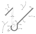
- FIG. 2 is a cross-sectional view showing the liquid receiver of the rotating electrical machine according to the first embodiment.
- the liquid receiver 20 has a spreading part 21 and a liquid holding / transferring part 22.
- the liquid holding / transferring portion 22 is configured to collect and hold the liquid received by the spreading portion 21 so as to be transferred. Further, the liquid holding / transferring portion 22 forms a long and narrow channel extending in the longitudinal direction and opened upward.
- the liquid holding / transferring portion 22 extends substantially horizontally, but has a function of transferring the stored liquid in the longitudinal direction, and thus has a flow gradient so as to form a flow path in the longitudinal direction.
- the liquid holding / transferring part 22 has a smooth curved surface in a direction perpendicular to the longitudinal direction.
- the spreading portion 21 is a plate having a spreading shape and extends along the liquid holding / transferring portion 22.
- the spreading part 21 is inclined with a large gradient in the direction in which the received liquid flows down toward the liquid holding and transferring part 22. That is, the lower side part 21a which is one side part of the spreading part 21 is lower than the upper side part 21b which is the other side part.
- the first side portion 22 a that is one side portion of the liquid holding / transferring portion 22 is connected to the lower side portion 21 a of the spreading portion 21.
- the tip of the second side portion 22b protrudes from the extended line from the spread portion 21. That is, as shown in FIG. 2, when ⁇ is a height at which the tip of the second side portion 22b protrudes from the extended surface from the widened portion 21, ⁇ is positive. As ⁇ increases, the liquid catching capacity of the liquid receiver 20 improves. On the other hand, as ⁇ increases, the resistance to the flow of the cooling gas increases. Therefore, since both are contradictory, by setting ⁇ having an appropriate dimension, it is possible to secure the liquid capturing ability while suppressing the resistance of the flow of the cooling gas.
- Adjacent liquid receptacles 20 overlap each other in the horizontal direction, and w in FIG. 2 is a positive value. That is, the liquid receiving unit 25 as viewed from above the liquid receiving unit 25 covers the front surface of the rotating electrical machine main body 8 below the liquid receiving unit 25.
- the liquid receiving unit 25 covers the rotating electrical machine main body 8 as viewed from above, the liquid such as the cooling liquid or the condensate does not fall directly on the rotating electrical machine main body 8.
- the liquid drops 20 fall on the spreading part 21 or the liquid holding / transferring part 22.
- the liquid dropped on the spreading part 21 flows down into the liquid holding / transferring part 22 along the inclination of the spreading part 21.
- the liquid that has flowed down from the spreading portion 21 to the liquid holding / transferring portion 22 and the liquid that has dropped directly to the liquid holding / transferring portion 22 are transferred through the flow path in the longitudinal direction of the liquid holding / transferring portion 22.
- the cooling gas sent from the upper part to the liquid receiving unit 25 changes its direction along the spreading part 21 after flowing between the liquid receiving parts 20 adjacent to each other as shown by a solid line A in FIG.
- the cooling gas changes its direction downward as shown by a solid line B in FIG. 2 when passing over the liquid holding / transferring part 22 after passing over the spreading part 21 and passing over the liquid holding / transferring part 22. It flows out from the liquid receiving unit 25 downward.
- the cooling gas passes over the spreading part 21, there is a possibility that the liquid flowing down on the spreading part 21 is accompanied.
- the cooling gas accompanied by the liquid on the surface of the spreading part 21 flowing down the spreading part 21 flows along the surface of the spreading part 21.
- the second side portion 22 b of the liquid holding / transferring portion 22 protrudes from the extended surface of the spreading portion 21. Therefore, the cooling gas accompanied by the liquid on the surface of the spreading part 21 collides with the second side part 22 b of the liquid holding / transferring part 22.
- the tangential direction of the second side portion 22 b of the liquid holding and transporting portion 22 opposite to the first side portion 22 a, and the extension line from the spreading portion 21 Is formed to be smaller than 90 degrees.
- the liquid accompanying the cooling gas colliding with the second side portion 22b of the liquid holding / transferring portion 22 retains the liquid rather than being accompanied again by the cooling gas flow from the liquid holding / transferring portion 22. It is hold
- the liquid such as the leaked cooling liquid or the condensate condensed with the moisture of the cooling gas is reliably captured and transferred.
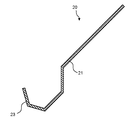
- FIG. 3 is a cross-sectional view showing a liquid receiver of a rotating electrical machine according to the second embodiment.
- This embodiment is a modification of the first embodiment.
- the liquid holding / transferring portion 23 according to the first embodiment is formed to have a smooth curved surface in a direction perpendicular to the longitudinal direction.
- the liquid holding / transferring portion 23 in the second embodiment is formed to have a plurality of planes connected to each other in a direction perpendicular to the longitudinal direction.
- the burden of designing and manufacturing the liquid receiver 20 can be reduced and the cost can be reduced.
- the features of each embodiment may be combined.
- the shape of the liquid holding and transporting section in the cross section is formed so as to have the smooth curve of the first embodiment and linearly configured in the second embodiment. It may be possible to have a curved portion and a straight line portion in combination with the feature of being.
Landscapes
- Engineering & Computer Science (AREA)
- Power Engineering (AREA)
- Chemical & Material Sciences (AREA)
- Combustion & Propulsion (AREA)
- Mechanical Engineering (AREA)
- General Engineering & Computer Science (AREA)
- Motor Or Generator Cooling System (AREA)
- Motor Or Generator Frames (AREA)
Abstract
Description
図1は、第1の実施形態に係る回転電機の構成を示す立断面図である。回転電機10は、回転子1、固定子2を有する。回転子1および固定子2からなる回転電機本体8は、ケーシング5内に収納されている。回転子1は、軸方向に延びるシャフト1aの径方向の周囲に配され、シャフト1aの回転とともに回転する。シャフト1aは、その軸方向の両端でケーシング5を貫通しており、ケーシング5にそれぞれ固定された両側の軸受4によって回転可能に軸支されている。固定子2は、回転子1の外周に回転子1と半径方向に間隔を空けて配設されている。固定子2は、固定子鉄心2aおよび固定子鉄心2aに巻回された固定子巻線3を有する。
図3は、第2の実施形態に係る回転電機の液受けを示す横断面図である。本実施形態は第1の実施形態の変形である。第1の実施形態に係る液保持移送部23は、長手方向に垂直な方向に滑らかな曲面を有するように形成されている。一方、本第2の実施形態における液保持移送部23は、長手方向に垂直な方向に、互いに接続された複数の平面を有するように形成されている。
以上、本発明のいくつかの実施形態を説明したが、これらの実施形態は、例として提示したものであり、発明の範囲を限定することは意図していない。たとえば、取扱い対象がドラム缶の場合を示したが、周囲から把持することによって移動可能な形状であれば、その他の容器でもよい。
Claims (6)
- 密閉容器と、
回転可能に軸支された回転子と、前記回転子の外周に前記回転子と間隔を空けて配設された固定子とを有し、前記密閉容器内に配された回転電機本体と、
前記密閉容器内にあって、前記回転電機本体を冷却する冷却用気体を外部から供給される冷却液により冷却する熱交換器と、
前記密閉容器内にあって、前記冷却用気体を循環させるファンと、
前記熱交換器の下方であって前記回転電機本体の上方に配されて、長手方向に微小な流れ勾配をもって延びており、互いに平行で水平に並んでおり、前記熱交換器において漏えいが生じたときに漏えいした冷却液または前記冷却用気体の湿分が凝縮した凝縮液を受けて移送する複数の液受けを有する液受けユニットと、
を備え、
前記複数の液受けのそれぞれは、
前記冷却液および前記凝縮液を保持可能に形成され、前記長手方向に延びて上方に開放された流路を形成する液保持移送部と、
広がりを持った板状で、前記冷却液または前記凝縮液を受けて前記液保持移送部に向かって流下させる方向に前記液受けの流れ勾配よりも大きな勾配で傾斜している広がり部と、
を具備し、
前記液保持移送部の一方の側部である第1の側部は前記広がり部の下側側部と接続しており、前記長手方向に垂直な横断面において、前記第1の側部と反対側の前記液保持移送部の第2の側部の接線方向と、前記広がり部からの延長線とのなす角は90度よりも小さく形成されている、
ことを特徴とする回転電機。 - 隣接する液受けどうしは、互いに水平方向に重複していることを特徴とする請求項1に記載の回転電機。
- 前記横断面において、前記第2の側部の先端は、前記広がり部からの延長線より突出していることを特徴とする請求項1または請求項2に記載の回転電機。
- 前記液保持移送部は、前記長手方向に垂直な方向に滑らかな曲面を有するように形成されていることを特徴とする請求項1ないし請求項3のいずれか一項に記載の回転電機。
- 前記液保持移送部は、前記長手方向に垂直な方向に互いに接続された複数の平面を有するように形成されていることを特徴とする請求項1ないし請求項4のいずれか一項に記載の回転電機。
- 回転子と固定子とを有し密閉容器内に配された回転電機本体を冷却する冷却用気体を冷却する熱交換器を備える回転電機の前記熱交換器において漏えいが生じたときに漏えいした冷却液または前記冷却用気体の湿分が凝縮した凝縮液を受けて移送する複数の液受けを有する液受けユニットであって、前記液受けのそれぞれは、
前記冷却液および前記凝縮液を保持可能に形成され、前記長手方向に延びて上方に開放された流路を形成する液保持移送部と、
広がりを持った板状で、前記冷却液または前記凝縮液を受けて前記液保持移送部に向かって流下させる方向に傾斜している広がり部と、
を具備し、
前記液保持移送部の一方の側部である第1の側部は前記広がり部の下側側部と接続しており、前記長手方向に垂直な横断面において、前記第1の側部と反対側の前記液保持移送部の第2の側部の接線方向と、前記広がり部からの延長線とのなす角は90度よりも小さく形成されている、
ことを特徴とする液受けユニット。
Priority Applications (3)
| Application Number | Priority Date | Filing Date | Title |
|---|---|---|---|
| CN201380079678.7A CN105556805A (zh) | 2013-09-30 | 2013-09-30 | 贮液单元及旋转电机 |
| JP2015538641A JP6193386B2 (ja) | 2013-09-30 | 2013-09-30 | 液受けユニットおよび回転電機 |
| PCT/JP2013/005813 WO2015044985A1 (ja) | 2013-09-30 | 2013-09-30 | 液受けユニットおよび回転電機 |
Applications Claiming Priority (1)
| Application Number | Priority Date | Filing Date | Title |
|---|---|---|---|
| PCT/JP2013/005813 WO2015044985A1 (ja) | 2013-09-30 | 2013-09-30 | 液受けユニットおよび回転電機 |
Publications (1)
| Publication Number | Publication Date |
|---|---|
| WO2015044985A1 true WO2015044985A1 (ja) | 2015-04-02 |
Family
ID=52742200
Family Applications (1)
| Application Number | Title | Priority Date | Filing Date |
|---|---|---|---|
| PCT/JP2013/005813 Ceased WO2015044985A1 (ja) | 2013-09-30 | 2013-09-30 | 液受けユニットおよび回転電機 |
Country Status (3)
| Country | Link |
|---|---|
| JP (1) | JP6193386B2 (ja) |
| CN (1) | CN105556805A (ja) |
| WO (1) | WO2015044985A1 (ja) |
Cited By (1)
| Publication number | Priority date | Publication date | Assignee | Title |
|---|---|---|---|---|
| JP2017158398A (ja) * | 2016-03-04 | 2017-09-07 | 東芝三菱電機産業システム株式会社 | 回転電機 |
Families Citing this family (2)
| Publication number | Priority date | Publication date | Assignee | Title |
|---|---|---|---|---|
| US11044834B1 (en) * | 2020-02-21 | 2021-06-22 | Google Llc | Inverted liquid cooling system |
| CN112583190B (zh) * | 2020-11-03 | 2022-04-19 | 超音速智能技术(杭州)有限公司 | 一种单相单绕组同步电机 |
Citations (4)
| Publication number | Priority date | Publication date | Assignee | Title |
|---|---|---|---|---|
| JPS5717260U (ja) * | 1980-06-24 | 1982-01-28 | ||
| JPH04161U (ja) * | 1990-04-18 | 1992-01-06 | ||
| JPH0464081U (ja) * | 1990-10-08 | 1992-06-01 | ||
| JPH0644379U (ja) * | 1992-11-11 | 1994-06-10 | 株式会社東芝 | 全閉空気冷却器付回転電機 |
Family Cites Families (3)
| Publication number | Priority date | Publication date | Assignee | Title |
|---|---|---|---|---|
| CN102222998B (zh) * | 2010-04-13 | 2013-01-09 | 上海电气集团上海电机厂有限公司 | 用于电机上空水冷却器的漏水报警装置 |
| CN102035285B (zh) * | 2010-10-29 | 2012-09-05 | 中电电机股份有限公司 | 紧凑型空水冷却器 |
| CN202616932U (zh) * | 2012-03-18 | 2012-12-19 | 杭州银轮科技有限公司 | 一种智能化风力发电机组冷却器 |
-
2013
- 2013-09-30 WO PCT/JP2013/005813 patent/WO2015044985A1/ja not_active Ceased
- 2013-09-30 CN CN201380079678.7A patent/CN105556805A/zh active Pending
- 2013-09-30 JP JP2015538641A patent/JP6193386B2/ja not_active Expired - Fee Related
Patent Citations (4)
| Publication number | Priority date | Publication date | Assignee | Title |
|---|---|---|---|---|
| JPS5717260U (ja) * | 1980-06-24 | 1982-01-28 | ||
| JPH04161U (ja) * | 1990-04-18 | 1992-01-06 | ||
| JPH0464081U (ja) * | 1990-10-08 | 1992-06-01 | ||
| JPH0644379U (ja) * | 1992-11-11 | 1994-06-10 | 株式会社東芝 | 全閉空気冷却器付回転電機 |
Cited By (2)
| Publication number | Priority date | Publication date | Assignee | Title |
|---|---|---|---|---|
| JP2017158398A (ja) * | 2016-03-04 | 2017-09-07 | 東芝三菱電機産業システム株式会社 | 回転電機 |
| CN107154694A (zh) * | 2016-03-04 | 2017-09-12 | 东芝三菱电机产业系统株式会社 | 旋转电机 |
Also Published As
| Publication number | Publication date |
|---|---|
| JP6193386B2 (ja) | 2017-09-06 |
| CN105556805A (zh) | 2016-05-04 |
| JPWO2015044985A1 (ja) | 2017-03-02 |
Similar Documents
| Publication | Publication Date | Title |
|---|---|---|
| US20110227431A1 (en) | Dynamoelectric machine | |
| US10026541B2 (en) | Molded stationary induction apparatus and method for manufacturing molded stationary induction apparatus | |
| CN105191077B (zh) | 带有轴承端盖的电机 | |
| US20150372565A1 (en) | Generator cooling arrangement | |
| JP6193386B2 (ja) | 液受けユニットおよび回転電機 | |
| US9742235B2 (en) | Star disk for an electric machine | |
| JP5342955B2 (ja) | 回転電機 | |
| US20130093272A1 (en) | Rotary electric machine | |
| JP2010258318A (ja) | 吸湿呼吸装置 | |
| CN104505970A (zh) | 具有三风扇全循环冷却风路系统的三相异步电动机 | |
| CN204334189U (zh) | 具有三风扇全循环冷却风路系统的三相异步电动机 | |
| CN105071598A (zh) | 一种双冷却电机的内风路结构 | |
| US20110169379A1 (en) | Heat insulation structure for cooling fan | |
| CA2863921A1 (en) | Electric machine with closed circuit air cooling | |
| US10666115B2 (en) | Electric machine | |
| CN105324920B (zh) | 绕组型旋转电机 | |
| JP5550506B2 (ja) | 立軸回転電機 | |
| CN107769417A (zh) | 电动机 | |
| CN204316260U (zh) | 一种电机 | |
| CN211530707U (zh) | 一种高压电缆分线箱 | |
| JP2014526633A (ja) | 周囲の空気を案内するための塔壁補強部を具備する風力タービン塔 | |
| CN209627153U (zh) | 一种耐高温电动机 | |
| CN104578596A (zh) | 一种电机及其定子结构的加工方法 | |
| CN209497118U (zh) | 电力柜 | |
| WO2017081945A1 (ja) | 回転電機 |
Legal Events
| Date | Code | Title | Description |
|---|---|---|---|
| WWE | Wipo information: entry into national phase |
Ref document number: 201380079678.7 Country of ref document: CN |
|
| 121 | Ep: the epo has been informed by wipo that ep was designated in this application |
Ref document number: 13894351 Country of ref document: EP Kind code of ref document: A1 |
|
| ENP | Entry into the national phase |
Ref document number: 2015538641 Country of ref document: JP Kind code of ref document: A |
|
| NENP | Non-entry into the national phase |
Ref country code: DE |
|
| 122 | Ep: pct application non-entry in european phase |
Ref document number: 13894351 Country of ref document: EP Kind code of ref document: A1 |