WO2015037682A1 - Network connection system and method therefor - Google Patents
Network connection system and method therefor Download PDFInfo
- Publication number
- WO2015037682A1 WO2015037682A1 PCT/JP2014/074146 JP2014074146W WO2015037682A1 WO 2015037682 A1 WO2015037682 A1 WO 2015037682A1 JP 2014074146 W JP2014074146 W JP 2014074146W WO 2015037682 A1 WO2015037682 A1 WO 2015037682A1
- Authority
- WO
- WIPO (PCT)
- Prior art keywords
- application
- network connection
- information terminal
- portable information
- communication
- Prior art date
Links
Images


Classifications
-
- H—ELECTRICITY
- H04—ELECTRIC COMMUNICATION TECHNIQUE
- H04L—TRANSMISSION OF DIGITAL INFORMATION, e.g. TELEGRAPHIC COMMUNICATION
- H04L47/00—Traffic control in data switching networks
- H04L47/10—Flow control; Congestion control
- H04L47/24—Traffic characterised by specific attributes, e.g. priority or QoS
- H04L47/2408—Traffic characterised by specific attributes, e.g. priority or QoS for supporting different services, e.g. a differentiated services [DiffServ] type of service
-
- H—ELECTRICITY
- H04—ELECTRIC COMMUNICATION TECHNIQUE
- H04L—TRANSMISSION OF DIGITAL INFORMATION, e.g. TELEGRAPHIC COMMUNICATION
- H04L47/00—Traffic control in data switching networks
- H04L47/10—Flow control; Congestion control
- H04L47/20—Traffic policing
-
- H—ELECTRICITY
- H04—ELECTRIC COMMUNICATION TECHNIQUE
- H04L—TRANSMISSION OF DIGITAL INFORMATION, e.g. TELEGRAPHIC COMMUNICATION
- H04L47/00—Traffic control in data switching networks
- H04L47/10—Flow control; Congestion control
- H04L47/24—Traffic characterised by specific attributes, e.g. priority or QoS
- H04L47/2475—Traffic characterised by specific attributes, e.g. priority or QoS for supporting traffic characterised by the type of applications
-
- H—ELECTRICITY
- H04—ELECTRIC COMMUNICATION TECHNIQUE
- H04L—TRANSMISSION OF DIGITAL INFORMATION, e.g. TELEGRAPHIC COMMUNICATION
- H04L65/00—Network arrangements, protocols or services for supporting real-time applications in data packet communication
- H04L65/60—Network streaming of media packets
- H04L65/75—Media network packet handling
- H04L65/765—Media network packet handling intermediate
-
- H—ELECTRICITY
- H04—ELECTRIC COMMUNICATION TECHNIQUE
- H04L—TRANSMISSION OF DIGITAL INFORMATION, e.g. TELEGRAPHIC COMMUNICATION
- H04L65/00—Network arrangements, protocols or services for supporting real-time applications in data packet communication
- H04L65/80—Responding to QoS
Definitions
- the present invention relates to a network connection system used in a mobile network, and more particularly to a network connection system for specifically controlling priority / band control of a connection communication band of a specific application installed in a terminal device on a mobile network and the same It is about the method.
- application software is configured to connect to a specific service server placed on the Internet and receive various information from the service server to present information requested by the user on the smartphone. .
- IP packets from application software are transferred on a best effort basis, and the IP packets cannot be preferentially controlled so as to be selected for each application. Therefore, for example, control of giving priority to communication of application software that handles voice information such as an IP phone cannot be performed over other application software, leading to dissatisfaction with smartphone users.
- IP address of a specific smartphone in the router it is possible to set the IP address of a specific smartphone in the router in advance and preferentially control the connection from that smartphone, but in that case, not only the IP phone but also the connection of all applications of that smartphone is prioritized. Will be.
- preferentially control only connections addressed to a specific service server for example, recent IP telephone services are provided in cooperation with a plurality of servers. It is difficult to grasp all the IP addresses and set them in the router in advance.
- the present invention has been made in view of such circumstances, and provides a high-quality service with a very simple configuration even when a plurality of different applications are executed on a portable information terminal.
- An object of the present invention is to provide a network connection system that can be used.
- a bandwidth control router placed between a mobile network and the Internet
- a network connection system configured such that a plurality of application software installed in a mobile information terminal on a mobile network is connected to a service server on the Internet via the bandwidth control router,
- This system An application communication environment management server provided on the Internet, which detects the type of application trying to connect to the service server from a specific portable information terminal, and determines a connection policy (bandwidth control, priority communication) according to the type of application.
- the bandwidth control router is configured to transfer packets from the specified portable information terminal with priority control or a predetermined priority communication bandwidth according to a connection policy received from the application communication environment management server.
- a network connection system is provided.
- the application connection server displays the detection of the type of application that is going to connect to the service server from a specific portable information terminal as the frontmost display on the portable information terminal. This is done by receiving the type of application that is running.
- the application connection server includes, in a packet transmitted from the mobile information terminal, detection of the type of application that is going to connect to the service server from a specific mobile information terminal. This is based on the tag to be used.
- the tag is a process ID of the application generated by an OS of the portable information terminal or an identifier related to the process ID.
- the bandwidth control router sets different IP addresses or / and port numbers for each application included in the packet. Accordingly, according to an individual connection policy, the packet from the specified portable information terminal is transferred with priority control or a predetermined priority communication band.
- the bandwidth control router when a plurality of types of the applications are detected at the same time, the IP address or / and the port number for each application included in the packet Accordingly, the packet from the specified portable information terminal is transferred with priority control or a predetermined priority communication band according to the individual connection policy.
- the application connection environment management server refers to a table storing a type of application to be preferentially connected or bandwidth controlled and a connection policy of the application. A connection policy corresponding to the type of software is extracted from the table and transmitted to the bandwidth control router.
- the connection policy includes a setting of a communication priority or a communication band that is different for each specific application.
- the system of the present invention monitors the data communication amount of each portable communication terminal by the bandwidth control router, and downloads for each application according to the type of application active in the portable information terminal.
- a data communication amount recording unit for recording the data communication amount;
- a traffic volume upper limit determination unit that determines whether the data traffic volume for each application recorded by the data traffic volume recording unit has reached a predetermined upper limit value.
- the system preferably includes a communication limiting unit that limits packet transfer from the portable information terminal by the bandwidth limiting router in accordance with the determination by the communication amount upper limit determination unit.
- a line communication congestion level for each application is calculated, and a congestion level display interface for displaying the congestion level to a user who generates the congestion level is generated. It is preferable to have a congestion degree display portion. Further, it is preferable to have a communication amount display unit for generating a data communication amount display interface for displaying the data communication amount for each application recorded by the data communication amount recording unit to the user. Furthermore, it is preferable to charge the user based on the data communication amount for each application recorded by the data communication amount recording unit.
- connection policy includes a setting of a data compression degree that differs for each specific application.
- the system of the present invention includes a data conversion method setting in which the data compression degree of the connection policy differs for each specific application.
- the connection policy includes a setting of a time zone and a location where communication is possible for each specific application.
- the information specifying the mobile information terminal is an IP address of the information mobile terminal.
- the system of the present invention includes a user billing information acquisition unit that receives user billing information and associates it with a portable information terminal.
- the type of application received from the portable information terminal specifies the type of service provided by the application.
- the system of the present invention generates a setting interface for setting a connection condition for a user and sets the setting through the interface.
- the application software to be preferentially connected or the type of service provided by the application software includes at least application software or service for voice call.
- the system of the present invention is installed in the portable information communication terminal, and causes the portable information terminal to detect the type of application that is actively displayed on the display of the portable information terminal.
- the system of the present invention comprises means for detecting a process ID of an application installed on the portable information communication terminal and started on the portable information terminal.
- it includes an application management software program that includes a specific tag that is different for each process, and has a means for transmitting the information to the bandwidth control system together with information for specifying the portable state terminal.
- the system of the present invention is installed in the portable information communication terminal, Means for causing the portable information terminal to detect an IP address or / and a port number of an application started on the portable information terminal; for allowing the portable information terminal to uniquely identify the portable information terminal on a communication network; Means for acquiring the portable information terminal specifying information; and including the IP address and / or port number in a packet transmitted from the application in the portable information terminal, together with information for specifying the portable state terminal, the band control system And having an application management software program having means for transmitting the data.
- the system of the present invention is installed in the portable information communication terminal, and causes the portable information terminal to receive a communication state for each application from the bandwidth control system.
- An application management software program having means for displaying on a display is provided.
- a plurality of application software having a bandwidth control router placed between a mobile network and the Internet and installed in a portable information terminal on the mobile network is provided with the bandwidth
- the type of application to be connected to the server from the information terminal is detected, and the connection policy (control bandwidth, compression presence / absence, etc.) according to the type of application software and the band (information such as IP address) specifying the portable information terminal Process to send to control router
- the bandwidth control router preferentially controls the packet from the specified portable information terminal according to the connection policy (control bandwidth, compression presence / absence, etc.) received from the application connection environment management server. And a transferring method.
- FIG. 1 is an overall schematic configuration diagram showing a data communication environment through a mobile network.
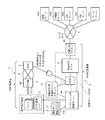
- FIG. 2 is an overall schematic configuration diagram showing a data communication environment according to an embodiment of the present invention.
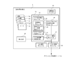
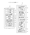
- FIG. 3 is a schematic diagram showing the application management software.
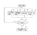
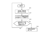
- FIG. 4 is a flowchart showing processing steps of the application management software.
- FIG. 5 is a schematic configuration diagram showing the application / infrastructure cooperation server.
- FIG. 6 is a flowchart showing processing steps of the application / infrastructure cooperation server.
- FIG. 7 is also a conceptual diagram for explaining a band control connection policy.
- FIG. 8 is also a conceptual diagram for explaining a band control connection policy.
- FIG. 9 is also a conceptual diagram for explaining a band control connection policy.
- FIG. 10 is also a conceptual diagram for explaining a band control connection policy.
- FIG. 10 is also a conceptual diagram for explaining a band control connection policy.
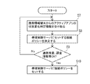
- FIG. 11 is a flowchart showing processing steps of the application / infrastructure cooperation server.
- FIG. 12 is also a diagram showing an example of a display screen of the portable information terminal.
- FIG. 13 is also a view showing a display screen example of the portable information terminal.
- FIG. 14 is also a flowchart showing a charging process performed by the charging server.
- FIG. 15 is a schematic diagram illustrating a bandwidth control method according to another embodiment.
- a network connection system including a bandwidth control router is a virtual mobile network operator (Mobile Virtual Network).
- Mobile Virtual Network An example provided by an operator (hereinafter referred to as “MVNO operator”) will be described.
- An MVNO operator does not own a physical mobile line network called a mobile network, but borrows it from a mobile communication operator (Mobile Network Operator, hereinafter referred to as “MNO operator”).
- MNO operator Mobile Network Operator
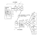
- FIG. 1 Data communication environment as a premise of the present invention
- a mobile network of the MNO operator is indicated by 1 in the figure
- a network connection system of the MVNO operator is indicated by 2.
- the service gateway 6 (SGW) on the MVO operator side is connected to the MVNO operator side. It is routed to the network connection system 2 of the MVNO operator via the packet data network gateway 7 (PGG), and then connected to various servers 10a to 10e on the Internet by the router 8 provided in the network connection system 2. It has become. Between the service gateway 6 on the MVO carrier side and the packet gateway 7 on the MVNO carrier side, a communication band based on a contract between the MVO carrier and the MVNO carrier, for example, 100 Mbps is secured. Yes.
- the user's portable information terminal 3 is a so-called smartphone, and has a CPU, a RAM, and a ROM (not shown).
- the operating system software program (hereinafter referred to as “OS”) such as iOS (trade name) and Android (trade name) and various application software programs (hereinafter simply referred to as “applications”) 3a to 3e are installed in the ROM.
- OS operating system software program
- applications application software programs
- data used by these OS and applications 3a to 3e is stored.
- the applications 3a to 3e installed in the user's portable information terminal 3 include video software 3a, IP phone 3b, SNS 3c, browser 3d, mailer 3e, etc., but the user can freely add additional applications according to his / her preference. It can be installed.
- the applications 3a to 3e on the portable information terminal 3 are appropriately called and expanded and executed on the RAM by the CPU, so that the mobile network 5 of the MNO carrier and the network connection system 2 of the MVNO carrier are used.
- various processes are performed by connecting to various servers 10a to 10e on the Internet 9 and performing necessary data communication with these servers 10a to 10e as appropriate.
- the router 8 provided in the network connection system 2 appropriately sends the packets 3a to 3e to the destination servers 10a to 10e based on the destination IP address included in the header information of the packet from the portable information terminal 3. It is supposed to transfer.
- the router 8 has a bandwidth control function 12 for controlling the transfer order and transfer speed of packets passing based on the IP address of the portable information terminal 3.
- the bandwidth control function is also called a QoS function, and can be roughly classified into “priority control” and “bandwidth control”.
- the priority control method is a method of distinguishing application types based on transmission source IP addresses for packets flowing on the network, and assigning absolute priority for each application. This is a method of assigning an upper limit of a communication band that can be used for each application.
- high priority application packets are always output with priority, or a larger communication bandwidth can be used, and packets related to high priority services can be transferred stably. Is possible.
- the router 8 needs to specify only the IP packets of the moving image software and the IP phone from the received many packets. The identification of this IP packet is generally performed based on the IP address and transfer port number of the source and destination.
- the target packet can be reliably identified by specifying the IP address of the terminal device at the source. It is done.
- this method cannot be used in the case where a plurality of apps with different priorities are running on the same terminal, such as the portable information terminal 3 described above. That is, if it is attempted to identify a packet using only IP address information, priority control / bandwidth control is performed even for communications that do not need to be prioritized. Further, in an environment in which an IP address is automatically allocated to a portable information terminal by DHCP, it is impossible to determine which terminal is the original by looking at the IP address.
- the application type may be identified based on the IP addresses of the destination servers 10a to 10e. For example, when a packet from the portable information terminal 3 is always connected to a specific IP telephone server 10b, the service type to which the target packet belongs can be assured by specifying the IP address of the IP telephone server 10b. Can be distinguished. However, some recent applications connect to many different servers in one application, and it has been difficult and practically impossible to specify addresses of all these servers.
- the system 2 of the MVNO operator has the present invention in addition to the bandwidth control router 8 having basically the same configuration and function as shown in FIG.
- Application / infrastructure cooperation server 14 (“application connection environment management server” of the present invention) corresponding to the functions of the network, line status / use amount sensing server 15 for monitoring the line market status, and charging according to the bandwidth used. It has a billing server 17 to be managed, a compression conversion proxy server 19, and application management software 16 installed in the portable information terminal 3.
- the system 2 on the MVNO provider side including the bandwidth control router 8 is referred to as a “bandwidth control system”.
- the application management software 16 is installed in the portable information terminal 3.
- the application management software 16 stores information on the types of applications 3a to 3e activated on the portable information terminal 3 together with the IP address / port number for identifying the portable state terminal 3 in the application / infrastructure linking server. 14 is transmitted.
- the application / infrastructure cooperation server 14 is provided in the system 2 of the MVNO operator and is designed to cooperate with the application management software 16 installed in the portable information terminal 3.
- the type of the applications 3a to 3e active on the information terminal 3 is detected, and the connection policy corresponding to the type of the applications 3a to 3e is sent to the bandwidth control router 8 together with the IP address / port number for specifying the portable information terminal 3 Has the function to set.
- the bandwidth control router 8 transfers packets from the specified mobile information terminal 3 with priority control or a predetermined priority communication bandwidth in accordance with the connection policy received from the application / infrastructure cooperation server 14. As a result, communication is performed with priority control according to the types of the applications 3a to 3e or with a predetermined priority communication band.
- the line status / usage monitoring server 15 monitors packets passing through the packet gateway 7 (PGW) provided in the system 2 on the MVNO provider side, and associates them with the IP address / port number of the portable information terminal 3. The amount of data communication is output and notified to the application / infrastructure cooperation server 14.
- PGW packet gateway 7
- FIG. 3 is a schematic diagram showing the portable information terminal 3 of the user.
- an OS (not shown), a plurality of different applications 3a to 3e, and application management software 16 of the present invention are installed.
- the application management software 16 includes an application detection module 22 that detects that a specific application is activated and activated in cooperation with an OS (not shown) of the portable information terminal 3, and a GPS or the like mounted on the portable information terminal 3.
- a position detection module 23 that detects the geographical position of the portable information terminal 3 in cooperation with the position detection device 21, and a terminal IP address / port number that detects the IP address and port number of the portable information terminal 3 in cooperation with the OS.
- the communication state of the active application of the mobile information terminal 3, the communication state of each application received from the server 14, and the line congestion state are transmitted to the server communication module 27 that transmits the state change determined by the mobile application state change determination module 25.
- an application communication state display unit 28 that displays on the display screen 29 of the portable information terminal 3.
- the application management software 16 is implemented in the form of an API for the OS.
- Reference numerals S1 to S6 in the figure are for referring to the steps, and correspond to steps S1 to S6 in the following description.
- the application activation detection module 22 is activated, and any of the applications 3a to 3e installed in the portable information terminal 3 is activated and activated on the display screen 29 of the portable information terminal 3 Is monitored (step S1 shown in the figure).
- “active” means that the activated application is displayed on the foreground of the display screen 29 of the terminal 3 and acquires the user's focus.
- the application activation detection module 22 monitors whether the application is active at certain time intervals or whether another application is activated and activated. When a specific application is active, the application activation detection module 22 outputs an application name (a unique name of an application output by the OS) and sends it to the active application state change determination module 26.
- the active application state change determination module 26 determines that the “active application state change” has occurred when the application name received from the application activation detection module 22 changes, that is, when the active application changes ( Step S2).
- the position detection module 23 monitors the signal from the location signal detection device 21 (step S3), and sends the current position coordinates of the mobile information terminal 3 to the active application state change determination module 26.
- the active application state change determination module 26 determines that an “active application state change” has occurred when the position coordinate information received from the position detection module fluctuates more than a certain value or when a certain condition is met (step S2).
- the terminal IP address / port number detection module 24 monitors the current IP address of the portable information terminal 3 and the number of the communication port currently used in conjunction with the communication module 30 of the portable information terminal 3.
- the acquired information is sent to the state change determination module 26 of the active application.
- the active application state change determination module 26 determines that an “active application state change” has occurred when the IP address or port name received from the terminal IP address / port number detection module changes (step S2).
- the application / parameter acquisition module 25 is linked with a specific application, acquires parameters associated with the application (step S5), and sends the parameters to the active application state change determination module 26.
- a connection destination URL corresponds to a browser
- a connection destination telephone number corresponds to an IP phone.
- the active application state change determination module 26 determines that “active application state change” has occurred when the parameter fluctuates (step S2).
- step S6 When the state change determination module 26 of the active application determines whether it is a “state change of the active application” based on the information received from each of the modules 22 to 25 as described above, Only the determination result is sent to the application / infrastructure cooperation server 14 (step S6).
- FIG. 5 is a schematic diagram showing a configuration of the application / infrastructure cooperation server 14 that receives the state change state.
- the application / infrastructure cooperation server 14 has an OS, RAM, various input / output interfaces (not shown), and a data storage unit 30 and a program storage unit 31 shown in FIG.
- the data storage unit 30 stores user information 32, application information 33 for bandwidth control in this system, and a user / application bandwidth control connection policy 34 set based on the terminal state change determination information. Yes.
- the application state change information acquisition module 36 that receives change information of the communication state of the application on the terminal 3 from the portable information terminal 3, and the information acquired by the application state change information acquisition module 36 Based on the policy setting unit 38 that acquires the communication band control / connection policy 34 for each user / application and transmits it to the communication band control router 8, and acquires the communication volume of the terminal 3 from the line status / usage sensing server 15.
- a data communication amount recording unit 39 stored in the data storage unit 30 in association with the user / application, and a communication upper limit for determining the communication upper limit by applying the communication amount for each application to the communication bandwidth control connection policy for each user / application.
- the application management software communication module 42 communicates with the server communication module 27, whereby communication with the portable information terminal 3 is performed.
- the application state change information acquisition module 36 receives the state change information transmitted from the application management software 16 of the portable information terminal 3 through the application management software communication module 42.
- this state information includes the application name, domain name base, coordinate position, application parameters of the application that is active on the user's terminal 3, and the IP address / port number used of the portable terminal 3.
- the communication band control policy setting unit 38 sets a control band connection policy for each user / application based on the state change information.
- the user information 32 (FIG. 5) is information for associating the portable information terminal 3 with the attributes of the user. Examples of such user information include the IP address and port number received from the terminal 3 above. Can be stored, and information on whether the user has a specific contract regarding the communication band can be included. When the specific contract is charged, the charging server 17 performs charging processing for the user through the charging processing module 43 as will be described later.
- the communication band control policy setting unit 38 recognizes that the state change information received from the terminal 3 is linked to a specific user by the user information 32.
- the application information 33 (FIG. 5) stores identification information of a specific application to be bandwidth controlled in this system.
- the application information 33 stores identification information of a specific application to be bandwidth controlled in this system.
- only a part of applications installed in the portable information terminal 3 are identified and band control connection is made, and the application name of band control target is registered in the application information 33.
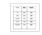
- information unique to the application information 33 is recognized in the application information 33 so as to recognize each software of a web browser, YouTube, Gmail, Facebook, Twitter, Yahoo (all are registered trademarks) and 050 (IP phone). Is stored.
- the communication band control policy setting unit 38 recognizes whether the application is a control target application based on the application information 33.
- the communication bandwidth control policy setting unit 38 specifies the connection policy for each user / application from the postscript bandwidth control connection policy 34 for each user / application by referring to the state change information, the user information 32, and the application information 33. Then, it is set in the bandwidth control router 8 (the compression degree is the compression conversion proxy 19 (hereinafter, description of the setting of the compression conversion proxy 19 is omitted as being included in the bandwidth control setting)).
- the specific connection policy 34 includes a communication band 34a, a data compression degree 34b, a communicable time zone 34c, a communicable place 34d, a data communication amount upper limit 34e, and a data communication remaining amount 34f.
- FIG. 7 to 10 are schematic diagrams for explaining the concept of the connection policy set in this embodiment.
- FIG. 7 is a conceptual diagram showing an example of policy setting related to the user application and the line speed (communication bandwidth) (34a).
- the default connection speed (connection bandwidth) other than the specific application described above is set to 100 kbps, and the LTE speed is set for the specific application.
- connection bandwidth connection bandwidth
- the LTE speed is set for the specific application.
- mobile connection is not permitted, and only WiFi connection is possible.
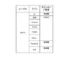
- FIG. 8 is a conceptual diagram showing an example of policy setting related to the user application and the remaining download amount (34e, 34f) for each application.
- the default is unlimited, a specific application whose connection speed is set to the LTE speed is initially set to 100 MB.
- the user can set an option to increase the upper limit, and in this case, the billing server 17 can perform billing processing for the usage exceeding the initial setting. ing.
- the billing method is not limited to this, and various methods can be adopted.
- the main connection policy is to set the line speed (bandwidth control) and the remaining download amount as described above.
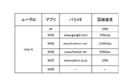
- various policies can be set. FIG. 9 comprehensively shows such examples.
- bandwidth control based on parameters specific to the application can be performed.
- a line speed is defined for each connection destination URL of the browser. This information is also stored in the data storage unit 30 as the connection policy 34.
- the server 14 receives the state change signal received from the application management software 16 by the application state change information acquisition module 36. (Step S7), identifies the user from the IP address and port number, applies the application name and user name to the user information 32, application information 33 and policy 34, and identifies the connection policy for the application (step S7). S8).
- connection policy shown above as a default is set
- the communication speed is 100 kbps
- the communication upper limit is set to unlimited regardless of the location and time.
- the connection policy specified by the YouTube in FIG. 9 is specified (step S8).
- the communication band control policy setting unit 38 checks other conditions, in this embodiment, the remaining communication amount (step S9). If the condition is cleared, the connection policy determined above is sent to the band control router 8. Transmit and set (step S10). This policy is set in the bandwidth control router 8 together with information for specifying the terminal 3, in this example, an IP address and a port number.
- the bandwidth control router 8 executes bandwidth control based on the connection policy corresponding to the IP address and port number of the transmission source included in the packet.
- the bandwidth control router 8 performs bandwidth control for all packets from the specific portable information terminal 3 at a time, and the bandwidth based on the application (in this case, the YouTube) that the user is actively using at that time. As a result, the speed band that matches the type of application is secured.
- the time lag from when the user switches the active application on the terminal 3 to when the bandwidth control is set becomes important.
- the time lag is 10 seconds or less. Yes, a new band will be set while the application is loaded, so the user will not experience the set delay. (Operation during bandwidth control communication)
- the operation of the application / infrastructure cooperation server 14 during the bandwidth control communication will be described with reference to FIG.
- the data communication amount recording unit 39 (shown in FIG. 5) of the server 14 monitors the communication state through the line status / use amount sensing server 15, and the unit time of the portable information terminal 3 of the specific user.
- Each traffic volume is recorded in association with the application that is communicating at that time (steps S11 and S12). As shown in the schematic diagram of FIG. 8, this recording is executed by appropriately updating the communication remaining amount (currently 50 MB in the example of the YouTube) of the communication band control connection policy 34 for each user / application.
- the communication upper limit determination unit 40 determines whether or not the remaining communication capacity of the user / application communication bandwidth control connection policy 34 has reached the upper limit (1G in the example of the YouTube) (step S13). If the current communication is continued and reached, the bandwidth control is returned to the default value and set in the control bandwidth server (step S14). As a result, the priority bandwidth control (75 Mbps in this example) of the application (in this example, youtube) is terminated, and the default (default) line speed is limited to 100 kbps.
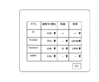
- the data communication state display processing unit 41 shown in FIG. 5 has a function of presenting the data communication amount and the line congestion level for each application to the user's portable information terminal 3. Specifically, the data communication state display processing unit 41 transmits time series data for each application to be presented to the user in response to a request from the terminal 3 of the user. This data is displayed on the screen as shown in FIGS. 12 and 13 by the communication status display unit 28 for each application provided in the application management software of the terminal 3 of the user.
- FIG. 12 is an interface showing the degree of line congestion for each application. According to this figure, although the Web connection is congested, it can be seen that YouTube still has room. By looking at such an interface, the user can know which software can perform comfortable communication.
- FIG. 13 shows a user interface for setting a connection policy for each application. From this screen, the user can set the connection speed, data compression degree, and download remaining amount for each application. That is, each setting value can be selected and set in a pull-down manner, and the setting can be made by pressing the OK button on this screen.
- the set value is written and updated in the data storage unit 30 (34) by the communication band control policy setting unit 38 of the application / infrastructure cooperation server 14. (Billing process)
- the billing server 17 is configured to perform billing according to the user's data usage and bandwidth.
- the billing server 17 cooperates with the billing processing module 43 of the app / infrastructure linking server 14, and the bandwidth control / connection policy for each user / application in the data storage unit 30. 34 is searched, and the registered communication band and usage (remaining amount) are acquired (S15).
- the billing processing module 43 transmits the information to the billing server 17 together with information specifying the user.
- the charging server 17 holds a charging policy (indicated by 17a in FIG. 2), and specifies a charging policy for each user based on the user information acquired from the cooperation server 14 (step S16).
- a charging policy for example, a user YouTube or the like can be set to have a low data communication fee for moving images and a high data communication fee such as WEB. Thereby, it is possible to perform a billing process according to the connection bandwidth and the usage amount for each application for the user (step S17).
- the present invention is not limited to the above-described embodiment, and various modifications can be made without changing the gist of the invention.
- connection band control of the terminal 3 is performed based on the type of application that is actively displayed on the forefront of the display screen 29 of the terminal 3 and gains the user's focus.
- bandwidth control may be performed based on the types of a plurality of applications 3a and 3b including applications that operate in the background.
- the OS for example, Android (registered trademark)
- the portable information terminal 3 When the OS (for example, Android (registered trademark)) of the portable information terminal 3 starts an application on the terminal 3, it also starts a process and outputs a unique process ID for each application.
- This process ID is detected by the IP address / port number detection module 25 of the application management software 50, and based on this, the per-process communication tag assignment module indicated by 50 in FIG. 15 assigns a different tag for each process number to the packet. To do.
- This tag may be the process ID itself of the above embodiment, the application name, or another identifier related to the process ID.
- a tag release module 51 provided in the system 2 of the MVNO operator, and is configured to delete the tag after bandwidth control.
- the application state change information acquisition module 36 receives the state change information transmitted from the application management software 16 of the portable information terminal 3 through the application management software communication module 42. receive.
- a tag assigned based on the process ID of each application started on the user's terminal 3 (in the above embodiment, the application name is output based on whether it is active). Domain name base, coordinate position, application parameters, process name, IP address / port number of the mobile terminal 3 are included.
- step S8 the communication band control policy setting unit 38 sets a control band connection policy for each user / application based on the state change information.
- the communication band control policy setting unit 38 sets a control band connection policy for each user / application based on the state change information.
- it is necessary to transmit the association between the tag and the application name to the application infrastructure cooperation server 14 in advance. Is executed by the state change determination module 26.
- the tunnel connection may be established by assigning a different port number or assigning a different IP address (virtual IP address) in addition to attaching a tag for each application.
- This function is executed by the function 50 of the tag addition module and the network stack. According to such a configuration, even when a plurality of applications are simultaneously communicating on the terminal 3, it is possible to individually control (band control, priority control) the communication band of each application packet. It should be noted that when the priority order is determined between applications, the connection policy determined on the management server side is used. In this case, the tunnel connection is executed by the tag cancellation module 51, and the IP address or / and port number for each application is deleted from each packet.
- connection policy 34 is not limited to that of the above embodiment, and other policies can be included.
- a specific image conversion method or moving image conversion method can be defined. For example, if the image is converted to black and white, it can be converted to high definition or set.
- the bandwidth control function is provided by a method of assigning a specific line speed value by bandwidth control.
- priority control relative rather than absolute value of the line speed
- This function may be provided by priority assignment).
- the connection policy is directly set in the bandwidth control router 8, but the present invention is not limited to this. It may be performed indirectly, such as through the PGW 7.
Abstract
[Solution] The present invention has an application-infrastructure cooperation server (14), provided on the Internet, for detecting the type of an application active on a specific portable information terminal (3) and setting, in a band control router (8), a connection policy corresponding to the type of the application along with information for specifying the portable information terminal (3), the band control router (8) transferring a packet from the specified portable information terminal (3) by priority control or by a prescribed priority communication band in accordance with the connection policy set by the application-infrastructure cooperation server (14).
Description
この発明は、モバイルネットワークで使用されるネットワーク接続システムに関し、特に、モバイルネットワーク上の端末機器にインストールされた特定アプリケーションの接続通信帯域を特異的に優先制御/帯域制御するためのネットワーク接続システム及びその方法に関するものである。
The present invention relates to a network connection system used in a mobile network, and more particularly to a network connection system for specifically controlling priority / band control of a connection communication band of a specific application installed in a terminal device on a mobile network and the same It is about the method.
近年、携帯情報端末、いわゆるスマートフォンの性能が向上し、ユーザが必要なアプリケーションソフトウェアを自由に選択しインストールすることができるようになってきている。ここで、多くのアプリケーションソフトウェアは、インターネット上に置かれた特定のサービスサーバと接続し、このサービスサーバから各種情報を受け取ることで、スマートフォン上にユーザが求める情報を提示するように構成されている。
In recent years, the performance of portable information terminals, so-called smartphones, has improved, and users can freely select and install necessary application software. Here, many application software is configured to connect to a specific service server placed on the Internet and receive various information from the service server to present information requested by the user on the smartphone. .
ここで、通常のネットワーク接続構成においては、アプリケーションソフトウェアからのIPパケットは、ベストエフォートで転送されるようになっており、アプリケーション毎に取捨選択するようにIPパケットを優先制御することはできない。したがって、例えば、IP電話のような音声情報を扱うようなアプリケーションソフトウェアの通信を他のアプリケーションソフトウェアよりも優先させるといった制御は行えず、スマートフォンのユーザの不満に繋がっていた。
Here, in a normal network connection configuration, IP packets from application software are transferred on a best effort basis, and the IP packets cannot be preferentially controlled so as to be selected for each application. Therefore, for example, control of giving priority to communication of application software that handles voice information such as an IP phone cannot be performed over other application software, leading to dissatisfaction with smartphone users.
一方、特定のスマートフォンのIPアドレスを予めルータに設定してそのスマートフォンからの接続を優先制御することは可能であるが、その場合、IP電話だけでなくそのスマートフォンの全てのアプリケーションの接続が優先制御されることになる。また、特定のサービスサーバ宛の接続のみを優先制御することは可能であるが、例えば最近のIP電話サービスは、複数のサーバを連携させて提供されるようになっているため、これら複数のサーバの全IPアドレスを、すべて把握して、予めルータに設定することは困難である。
On the other hand, it is possible to set the IP address of a specific smartphone in the router in advance and preferentially control the connection from that smartphone, but in that case, not only the IP phone but also the connection of all applications of that smartphone is prioritized. Will be. In addition, although it is possible to preferentially control only connections addressed to a specific service server, for example, recent IP telephone services are provided in cooperation with a plurality of servers. It is difficult to grasp all the IP addresses and set them in the router in advance.
すなわち、従来のモバイルキャリアのネットワーク接続システムでは、例えばIP電話アプリケーションのIPパケットだけを優先制御/帯域制御することで、ユーザに高品質な電話サービスを提供したいという希望に応えることが困難であった。
That is, in the conventional mobile carrier network connection system, for example, it is difficult to respond to the desire to provide a high-quality telephone service to the user by performing priority control / bandwidth control only for IP packets of IP telephone applications, for example. .
この発明は、このような事情を鑑みてなされたものであり、携帯情報端末上で異なる複数のアプリケーションが実行される場合であっても、非常に簡易な構成で高品質なサービスを提供することができるネットワーク接続システムを提供することを目的とする。
The present invention has been made in view of such circumstances, and provides a high-quality service with a very simple configuration even when a plurality of different applications are executed on a portable information terminal. An object of the present invention is to provide a network connection system that can be used.
上記目的を達成するため、この発明の第1の主要な観点によれば、モバイルネットワークとインターネットとの間に置かれた帯域制御ルータを有し、
モバイルネットワーク上の携帯情報端末にインストールされた複数のアプリケーションソフトウェアが、上記帯域制御ルータを介して上記インターネット上にあるサービスサーバに接続されるように構成されているネットワーク接続システムであって、
このシステムは、
インターネット上に設けられたアプリケーション通信環境管理サーバであって、特定の携帯情報端末から上記サービスサーバに接続しようとしているアプリケーションの種類を検出し、アプリケーションの種類に応じた接続ポリシー(帯域制御、優先通信、圧縮変換方法等)を上記携帯情報端末を特定する情報(IPアドレス、ポート番号等)と共に前記帯域制御ルータにセットするアプリケーション通信環境管理サーバを有し、
前記帯域制御ルータは、前記アプリケーション通信環境管理サーバから受け取った接続ポリシーに応じ、前記特定された携帯情報端末からのパケットを優先制御若しくは所定の優先通信帯域で転送するものである
ことを特徴とするネットワーク接続システムが提供される。 In order to achieve the above object, according to a first main aspect of the present invention, there is provided a bandwidth control router placed between a mobile network and the Internet,
A network connection system configured such that a plurality of application software installed in a mobile information terminal on a mobile network is connected to a service server on the Internet via the bandwidth control router,
This system
An application communication environment management server provided on the Internet, which detects the type of application trying to connect to the service server from a specific portable information terminal, and determines a connection policy (bandwidth control, priority communication) according to the type of application. And an application communication environment management server for setting the bandwidth control router together with information (IP address, port number, etc.) for identifying the portable information terminal),
The bandwidth control router is configured to transfer packets from the specified portable information terminal with priority control or a predetermined priority communication bandwidth according to a connection policy received from the application communication environment management server. A network connection system is provided.
この発明の一の実施形態によれば、前記アプリケーション接続サーバは、特定の携帯情報端末から上記サービスサーバに接続しようとしているアプリケーションの種類の検出を、前記携帯情報端末上で最前面にアクティブ表示されているアプリケーションの種類を受信することで行うものである。
According to one embodiment of the present invention, the application connection server displays the detection of the type of application that is going to connect to the service server from a specific portable information terminal as the frontmost display on the portable information terminal. This is done by receiving the type of application that is running.
この発明の別の一の実施形態によれば、前記アプリケーション接続サーバは、特定の携帯情報端末から上記サービスサーバに接続しようとしているアプリケーションの種類の検出を、携帯情報端末から送信されたパケットに含まれるタグに基づいて行うものである。
According to another embodiment of the present invention, the application connection server includes, in a packet transmitted from the mobile information terminal, detection of the type of application that is going to connect to the service server from a specific mobile information terminal. This is based on the tag to be used.
この発明のさらなる別の一の実施形態によれば、前記タグは、前記携帯情報端末のOSが生成した前記アプリケーションのプロセスID若しくはこのプロセスIDに関連する識別子である。
According to still another embodiment of the present invention, the tag is a process ID of the application generated by an OS of the portable information terminal or an identifier related to the process ID.
この発明の更なる別の一の実施形態によれば、前記帯域制御ルータは、同時に複数種類の前記アプリケーションが検出された場合、前記パケットに含まれるアプリケーション毎に異なるIPアドレス若しくは/及びポート番号に応じて、個別の接続ポリシーに応じ、前記特定された携帯情報端末からのパケットを優先制御若しくは所定の優先通信帯域で転送するものである。
According to still another embodiment of the present invention, when a plurality of types of the applications are detected at the same time, the bandwidth control router sets different IP addresses or / and port numbers for each application included in the packet. Accordingly, according to an individual connection policy, the packet from the specified portable information terminal is transferred with priority control or a predetermined priority communication band.
この発明の更なる別の一の実施形態によれば、前記帯域制御ルータは、同時に複数種類の前記アプリケーションが種類が検出された場合、前記パケットに含まれるアプリケーション毎のIPアドレス若しくは/及びポート番号に応じて、個別の接続ポリシーに応じ、前記特定された携帯情報端末からのパケットを優先制御若しくは所定の優先通信帯域で転送するものである。
この発明の更なる別の一実施形態によれば、前記アプリケーション接続環境管理サーバは、優先接続若しくは帯域制御するべきアプリケーションの種類とそのアプリケーションの接続ポリシーとが格納されているテーブルを参照し、アプリケーションソフトウェアの種類に応じた接続ポリシーを上記テーブルから取り出して上記帯域制御ルータに送信するものである。 According to still another embodiment of the present invention, the bandwidth control router, when a plurality of types of the applications are detected at the same time, the IP address or / and the port number for each application included in the packet Accordingly, the packet from the specified portable information terminal is transferred with priority control or a predetermined priority communication band according to the individual connection policy.
According to still another embodiment of the present invention, the application connection environment management server refers to a table storing a type of application to be preferentially connected or bandwidth controlled and a connection policy of the application. A connection policy corresponding to the type of software is extracted from the table and transmitted to the bandwidth control router.
また別の一実施形態によれば、この発明のシステムは、前記接続ポリシーは、特定のアプリケーション毎に異なる通信優先度若しくは通信帯域の設定を含むものである。
According to another embodiment, in the system of the present invention, the connection policy includes a setting of a communication priority or a communication band that is different for each specific application.
更なる別の一実施形態によれば、この発明のシステムは、帯域制御ルータによる携帯通信端末毎のデータ通信量を監視し、携帯情報端末でアクティブなアプリケーションの種類に応じて、アプリケーション毎のダウンロードデータ通信量を記録するデータ通信量記録部を有する。この場合、上記携帯情報端末でアクティブなアプリケーションの種類に応じ、前記データ通信量記録部で記録されたアプリケーション毎のデータ通信量が所定の上限値に達したかを判断する通信量上限判断部を有するものであり、このシステムは、上記通信量上限判断部の判断に応じて前記帯域制限ルータによる当該携帯情報端末からのパケットの転送を制限する通信制限部を有することが好ましい。
According to still another embodiment, the system of the present invention monitors the data communication amount of each portable communication terminal by the bandwidth control router, and downloads for each application according to the type of application active in the portable information terminal. A data communication amount recording unit for recording the data communication amount; In this case, according to the type of application active in the portable information terminal, a traffic volume upper limit determination unit that determines whether the data traffic volume for each application recorded by the data traffic volume recording unit has reached a predetermined upper limit value. The system preferably includes a communication limiting unit that limits packet transfer from the portable information terminal by the bandwidth limiting router in accordance with the determination by the communication amount upper limit determination unit.
また、前記データ通信量記録部で記録されたアプリケーション毎のデータ通信量に基づき、アプリケーション毎の回線通信混雑度を算出し、前記混雑度を表示するユーザに表示するための混雑度表示インタフェースを生成する混雑度表示部を有することが好ましい。また、前記データ通信量記録部で記録されたアプリケーション毎のデータ通信量をユーザに表示するためのデータ通信量表示インタフェースを生成する通信量表示部を有することが好ましい。さらに、前記データ通信量記録部で記録されたアプリケーション毎のデータ通信量に基づき、ユーザ課金することが好ましい。
Further, based on the data traffic volume for each application recorded by the data traffic volume recording unit, a line communication congestion level for each application is calculated, and a congestion level display interface for displaying the congestion level to a user who generates the congestion level is generated. It is preferable to have a congestion degree display portion. Further, it is preferable to have a communication amount display unit for generating a data communication amount display interface for displaying the data communication amount for each application recorded by the data communication amount recording unit to the user. Furthermore, it is preferable to charge the user based on the data communication amount for each application recorded by the data communication amount recording unit.
更なる別の一実施形態によれば、この発明のシステムは、前記接続ポリシーは、特定のアプリケーション毎に異なるデータ圧縮度の設定を含むものである。
According to still another embodiment, in the system of the present invention, the connection policy includes a setting of a data compression degree that differs for each specific application.
更なる別の一実施形態によれば、この発明のシステムは、前記接続ポリシーのデータ圧縮度は、特定のアプリケーション毎に異なるデータ変換方法の設定を含むものである。
According to still another embodiment, the system of the present invention includes a data conversion method setting in which the data compression degree of the connection policy differs for each specific application.
更なる別の一実施形態によれば、この発明のシステムは、前記接続ポリシーは、特定のアプリケーション毎に異なる通信可能な時間帯、場所の設定を含むものである。
According to still another embodiment, in the system of the present invention, the connection policy includes a setting of a time zone and a location where communication is possible for each specific application.
更なる別の一実施形態によれば、この発明のシステムは、前記携帯情報端末を特定する情報は、前記情報携帯端末のIPアドレスである。
According to still another embodiment, in the system of the present invention, the information specifying the mobile information terminal is an IP address of the information mobile terminal.
更なる別の一実施形態によれば、この発明のシステムは、ユーザ課金情報を受け取り、携帯情報端末に関連付けるユーザ課金情報取得部を有する。
According to still another embodiment, the system of the present invention includes a user billing information acquisition unit that receives user billing information and associates it with a portable information terminal.
更なる別の一実施形態によれば、この発明のシステムは、前記携帯情報端末から受け取るアプリケーションの種類は、当該アプリケーションが提供するサービスの種類を特定するものである。
According to still another embodiment, in the system of the present invention, the type of application received from the portable information terminal specifies the type of service provided by the application.
更なる別の一実施形態によれば、この発明のシステムは、ユーザに、接続条件を設定するための設定インタフェースを生成し、そのインタフェースを通して設定するようにするものである。
According to still another embodiment, the system of the present invention generates a setting interface for setting a connection condition for a user and sets the setting through the interface.
更なる別の一実施形態によれば、この発明のシステムは、前記優先接続するべきアプリケーションソフトウェア若しくはそのアプリケーションソフトウェアが提供するサービスの種別は、音声通話のためのアプリケーションソフトウェア若しくはサービスを少なくとも含むものである。
According to still another embodiment, in the system of the present invention, the application software to be preferentially connected or the type of service provided by the application software includes at least application software or service for voice call.
更なる別の一実施形態によれば、この発明のシステムは、前記携帯情報通信端末にインストールされ、前記携帯情報端末に、この携帯情報端末のディスプレイ上にアクティブ表示されたアプリケーションの種類を検出させる手段と;前記携帯情報端末に、この携帯情報端末を通信ネットワーク上でユニークに特定するための携帯情報端末特定情報を取得させる手段と;前記携帯情報端末に、上記アプリケーションの種別を携帯状態端末を特定する情報と共に前記帯域制御システムに送信させる手段とを有するアプリケーション管理ソフトウエアプログラムを有するものである。
According to still another embodiment, the system of the present invention is installed in the portable information communication terminal, and causes the portable information terminal to detect the type of application that is actively displayed on the display of the portable information terminal. Means for causing the portable information terminal to acquire portable information terminal identification information for uniquely identifying the portable information terminal on a communication network; and And an application management software program having means for transmitting to the bandwidth control system together with information to be specified.
更なる別の一実施形態によれば、この発明のシステムは、 前記携帯情報通信端末にインストールされ、前記携帯情報端末に、この携帯情報端末上で起動されたアプリケーションのプロセスIDを検出させる手段と;前記携帯情報端末に、この携帯情報端末を通信ネットワーク上でユニークに特定するための携帯情報端末特定情報を取得させる手段と;前記携帯情報端末に、上記アプリケーションから送信されるパケットに上記プロセスID若しくはプロセス毎に異なる特定のタグを含ませ、携帯状態端末を特定する情報と共に前記帯域制御システムに送信させる手段とを有するアプリケーション管理ソフトウエアプログラムを有するものである。
According to yet another embodiment, the system of the present invention comprises means for detecting a process ID of an application installed on the portable information communication terminal and started on the portable information terminal. Means for causing the portable information terminal to acquire portable information terminal identification information for uniquely identifying the portable information terminal on a communication network; and the process ID in a packet transmitted from the application to the portable information terminal; Alternatively, it includes an application management software program that includes a specific tag that is different for each process, and has a means for transmitting the information to the bandwidth control system together with information for specifying the portable state terminal.
更なる別の一実施形態によれば、この発明のシステムは、前記携帯情報通信端末にインストールされ、
前記携帯情報端末に、この携帯情報端末上で起動されたアプリケーションのIPアドレス若しくは/及びポート番号を検出させる手段と;前記携帯情報端末に、この携帯情報端末を通信ネットワーク上でユニークに特定するための携帯情報端末特定情報を取得させる手段と;前記携帯情報端末に、上記アプリケーションから送信されるパケットに上記IPアドレス及び/若しくはポート番号を含ませ、携帯状態端末を特定する情報と共に前記帯域制御システムに送信させる手段とを有するアプリケーション管理ソフトウエアプログラムを有するものである。 According to yet another embodiment, the system of the present invention is installed in the portable information communication terminal,
Means for causing the portable information terminal to detect an IP address or / and a port number of an application started on the portable information terminal; for allowing the portable information terminal to uniquely identify the portable information terminal on a communication network; Means for acquiring the portable information terminal specifying information; and including the IP address and / or port number in a packet transmitted from the application in the portable information terminal, together with information for specifying the portable state terminal, the band control system And having an application management software program having means for transmitting the data.
更なる別の一実施形態によれば、この発明のシステムは、前記携帯情報通信端末にインストールされ、前記携帯情報端末に、前記帯域制御システムからアプリケーション毎の通信状態を受け取らせこの携帯状態端末のディスプレイ上に表示する手段を有するアプリケーション管理ソフトウエアプログラムを有するものである。
According to still another embodiment, the system of the present invention is installed in the portable information communication terminal, and causes the portable information terminal to receive a communication state for each application from the bandwidth control system. An application management software program having means for displaying on a display is provided.
この発明の第2の主要な観点によれば、モバイルネットワークとインターネットとの間に置かれた帯域制御ルータを有し、モバイルネットワーク上の携帯情報端末にインストールされた複数のアプリケーションソフトウェアが、上記帯域制御ルータを介して上記インターネット上にあるサービスサーバに接続されるように構成されているネットワーク接続システムにより実行される方法であって、インターネット上に設けられたアプリケーション接続環境管理サーバで、特定の携帯情報端末から前記サーバに接続しようとするアプリケーションの種類を検出し、アプリケーションソフトウェアの種類に応じた接続ポリシー(制御帯域・圧縮有無等)を上記携帯情報端末を特定する情報(IPアドレス等)と共に帯域制御ルータに送信する工程と、前記帯域制御ルータが、前記アプリケーション接続環境管理サーバから受け取った接続ポリシー(制御帯域・圧縮有無等)に応じ、前記特定された携帯情報端末からのパケットを優先制御若しくは所定の優先通信帯域で転送する工程とを有することを特徴とする方法が提供される。
According to a second main aspect of the present invention, a plurality of application software having a bandwidth control router placed between a mobile network and the Internet and installed in a portable information terminal on the mobile network is provided with the bandwidth A method executed by a network connection system configured to be connected to a service server on the Internet via a control router, wherein the application connection environment management server provided on the Internet The type of application to be connected to the server from the information terminal is detected, and the connection policy (control bandwidth, compression presence / absence, etc.) according to the type of application software and the band (information such as IP address) specifying the portable information terminal Process to send to control router And the bandwidth control router preferentially controls the packet from the specified portable information terminal according to the connection policy (control bandwidth, compression presence / absence, etc.) received from the application connection environment management server. And a transferring method.
この発明の上記特許請求の範囲に記載していない他の特徴については、この後の発明の最良の実施形態及び図面中に明らかにされる。
Other features not described in the claims of the present invention will be clarified in the best embodiment of the present invention and the drawings.
この実施形態では、帯域制御ルータを含むネットワーク接続システムが、仮想移動体通信事業者(Mobile Virtual Network
Operator、以下「MVNO事業者」という)によって提供される場合を例にとって説明する。 In this embodiment, a network connection system including a bandwidth control router is a virtual mobile network operator (Mobile Virtual Network).
An example provided by an operator (hereinafter referred to as “MVNO operator”) will be described.
Operator、以下「MVNO事業者」という)によって提供される場合を例にとって説明する。 In this embodiment, a network connection system including a bandwidth control router is a virtual mobile network operator (Mobile Virtual Network).
An example provided by an operator (hereinafter referred to as “MVNO operator”) will be described.
MVNO事業者とは、モバイルネットワークという物理的な移動体回線網を自社では持たず、実際に保有する移動体通信事業者(Mobile Network Operator、以下「MNO事業者」という)から借りて、自社ブランドで通信サービスを行う事業者のことをいう。
An MVNO operator does not own a physical mobile line network called a mobile network, but borrows it from a mobile communication operator (Mobile Network Operator, hereinafter referred to as “MNO operator”). A business operator that provides communication services.
本発明の特徴的構成の説明をする前に、本発明の理解の便宜のため、まず図1を参照して、モバイルネットワークを通したデータ通信環境の一例について説明する。
(本願発明の前提となるデータ通信環境)
図1中、図に1で示すのがMNO事業者のモバイルネットワークであり、2で示すのがMVNO事業者のネットワーク接続システムである。 Before describing the characteristic configuration of the present invention, an example of a data communication environment through a mobile network will be described first with reference to FIG. 1 for the convenience of understanding the present invention.
(Data communication environment as a premise of the present invention)
In FIG. 1, a mobile network of the MNO operator is indicated by 1 in the figure, and a network connection system of the MVNO operator is indicated by 2.
MVNO事業者と契約したユーザの携帯情報端末3は、基地局4を介してMNO事業者のモバイルネットワーク5に接続された後、MVO事業者側のサービスゲートウェイ6(SGW)からMVNO事業者側のパケットデータネットワークゲートウェイ7(PGG)を介してMVNO事業者のネットワーク接続システム2にルーティングされ、ついで、このネットワーク接続システム2に設けられたルータ8によってインターネットの各種サーバ10a~10eに接続されるようになっている。これらMVO事業者側のサービスゲートウェイ6とMVNO事業者側のパケットゲートウェイ7の間には、MVO事業者とMVNO事業者との契約に基づいた通信帯域、例えば100Mbpsが確保されるように構成されている。
After the mobile information terminal 3 of the user who has contracted with the MVNO operator is connected to the mobile network 5 of the MNO operator via the base station 4, the service gateway 6 (SGW) on the MVO operator side is connected to the MVNO operator side. It is routed to the network connection system 2 of the MVNO operator via the packet data network gateway 7 (PGG), and then connected to various servers 10a to 10e on the Internet by the router 8 provided in the network connection system 2. It has become. Between the service gateway 6 on the MVO carrier side and the packet gateway 7 on the MVNO carrier side, a communication band based on a contract between the MVO carrier and the MVNO carrier, for example, 100 Mbps is secured. Yes.
前記ユーザの携帯情報端末3は、いわゆるスマートフォンであって、図示しないCPU、RAM、及びROMを有する。ROMにはiOS(商品名)やAndroid(商品名)等のオペレーションシステムソフトウェアプログラム(以下「OS」という)と、各種アプリケーションソフトウェアプログラム(以下、単に「アプリケーション」という)3a~3eがインストールされている他、これらのOSやアプリ3a~3eで利用するデータが格納されるようになっている。
The user's portable information terminal 3 is a so-called smartphone, and has a CPU, a RAM, and a ROM (not shown). The operating system software program (hereinafter referred to as “OS”) such as iOS (trade name) and Android (trade name) and various application software programs (hereinafter simply referred to as “applications”) 3a to 3e are installed in the ROM. In addition, data used by these OS and applications 3a to 3e is stored.
このユーザの携帯情報端末3にインストールされたアプリケーション3a~3eとしては、動画ソフト3a、IP電話3b、SNS3c、ブラウザ3d、メーラ3e等があるが、ユーザが自己の好みで追加のアプリケーションを自由にインストールできるようになっている。これら携帯情報端末3上のアプリ3a~3eは、CPUにより適宜RAM上に呼び出されて展開され実行されることで、上記MNO事業者のモバイルネットワーク5とMVNO事業者のネットワーク接続システム2を介して、インターネット9上にある各種サーバ10a~10eに接続し、これらサーバ10a~10eとの間で適宜必要なデータ通信を行うことで各種処理を行うようになっている。
The applications 3a to 3e installed in the user's portable information terminal 3 include video software 3a, IP phone 3b, SNS 3c, browser 3d, mailer 3e, etc., but the user can freely add additional applications according to his / her preference. It can be installed. The applications 3a to 3e on the portable information terminal 3 are appropriately called and expanded and executed on the RAM by the CPU, so that the mobile network 5 of the MNO carrier and the network connection system 2 of the MVNO carrier are used. In addition, various processes are performed by connecting to various servers 10a to 10e on the Internet 9 and performing necessary data communication with these servers 10a to 10e as appropriate.
この図に示すように上記携帯情報端末のアプリ3a~3eは、実行されるとき、異なるIPアドレスを有する複数のサーバ10a~10eと接続される。この場合、前記ネットワーク接続システム2に設けられたルータ8は、上記携帯情報端末3からのパケットのヘッダ情報に含まれる宛先IPアドレスに基づき、当該パケット3a~3eを宛先のサーバ10a~10eに適宜転送するようになっている。
As shown in this figure, when the applications 3a to 3e of the portable information terminal are executed, they are connected to a plurality of servers 10a to 10e having different IP addresses. In this case, the router 8 provided in the network connection system 2 appropriately sends the packets 3a to 3e to the destination servers 10a to 10e based on the destination IP address included in the header information of the packet from the portable information terminal 3. It is supposed to transfer.
このルータ8は、携帯情報端末3のIPアドレスに基づいて通過するパケットの転送順序や転送速度を制御するための帯域制御機能12を備えている。帯域制御機能は、QoS機能とも呼ばれ、大きく、「優先制御」と「帯域制御」の二つに区別できる。この発明に当てはめた場合、優先制御方式は、ネットワーク上に流れているパケットについて送出元IPアドレスによりアプリケーション種別を区別し、アプリケーション毎に絶対的な優先度を割り当てる方法であり、帯域制御機能とは、アプリケーション毎に使用できる通信帯域の上限を割り当てる方式である。
The router 8 has a bandwidth control function 12 for controlling the transfer order and transfer speed of packets passing based on the IP address of the portable information terminal 3. The bandwidth control function is also called a QoS function, and can be roughly classified into “priority control” and “bandwidth control”. When applied to the present invention, the priority control method is a method of distinguishing application types based on transmission source IP addresses for packets flowing on the network, and assigning absolute priority for each application. This is a method of assigning an upper limit of a communication band that can be used for each application.
この帯域制御によれば、優先度の高いアプリケーションのパケットが常に優先して出力されるか、若しくはより大きい通信帯域を使用できることができ、優先度の高いサービスに係るパケットを安定して転送することが可能になる。
According to this bandwidth control, high priority application packets are always output with priority, or a larger communication bandwidth can be used, and packets related to high priority services can be transferred stably. Is possible.
これらQoS制御においては、受け取ったIPパケットからアプリケーションの種類を正確に識別することが重要になる。一般に、動画ソフトやIP電話ソフトからの動画・音声のパケットは、品質を維持するために優先制御されるか広い通信帯域で転送される必要がある。この場合、上記ルータ8は、受け取った多くのパケットから動画ソフトやIP電話のIPパケットのみを特定する必要がある。このIPパケットの識別は一般に発信元や宛先のIPアドレスや転送ポート番号に基づいて行われる。
In these QoS controls, it is important to accurately identify the type of application from the received IP packet. Generally, moving image / sound packets from moving image software and IP phone software need to be preferentially controlled or transferred over a wide communication band in order to maintain quality. In this case, the router 8 needs to specify only the IP packets of the moving image software and the IP phone from the received many packets. The identification of this IP packet is generally performed based on the IP address and transfer port number of the source and destination.
例えば、IP電話専用機やVoIPゲートウエイなど、特定の端末装置が固定のIPアドレスで使用されている場合には、発信元の端末措置のIPアドレスを指定することで、対象のパケットを確実に見分けられる。
For example, when a specific terminal device is used with a fixed IP address, such as a dedicated IP phone or a VoIP gateway, the target packet can be reliably identified by specifying the IP address of the terminal device at the source. It is done.
しかしながら、上述した携帯情報端末3のように同一の端末上で優先度の違う複数のアプリが動いているようなケースではこの方法は利用できない。すなわち、IPアドレスの情報だけでパケットを識別しようとすると、優先する必要のない通信まで優先制御/帯域制御してしまうことになる。また、携帯情報端末に対してDHCPでIPアドレスを自動的に割り振る環境の場合、そもそもIPアドレスを見てもどの端末か判断できない。
However, this method cannot be used in the case where a plurality of apps with different priorities are running on the same terminal, such as the portable information terminal 3 described above. That is, if it is attempted to identify a packet using only IP address information, priority control / bandwidth control is performed even for communications that do not need to be prioritized. Further, in an environment in which an IP address is automatically allocated to a portable information terminal by DHCP, it is impossible to determine which terminal is the original by looking at the IP address.
一方、宛先サーバ10a~10eのIPアドレスに基づいてアプリケーション種別を識別する場合も考えられる。例えば、携帯情報端末3からのパケットが常に特定のIP電話サーバ10bに接続される場合、IP電話用サーバ10bのIPアドレスを指定することで、対象のパケットがどのサービス種別に属するかを確実に見分けることができる。しかし、近時のアプリケーションは、1つのアプリケーションで多数の異なるサーバに接続するものもあり、このすべてのサーバのアドレスを指定することは困難で実質的に不可能であるということがあった。
On the other hand, it may be possible to identify the application type based on the IP addresses of the destination servers 10a to 10e. For example, when a packet from the portable information terminal 3 is always connected to a specific IP telephone server 10b, the service type to which the target packet belongs can be assured by specifying the IP address of the IP telephone server 10b. Can be distinguished. However, some recent applications connect to many different servers in one application, and it has been difficult and practically impossible to specify addresses of all these servers.
前述したように、この発明は、このような事情に鑑みてなされたものである。
(この発明の特徴的構成)
以下、本願発明の特徴的構成を上記図1で説明したモバイル通信環境に適用した例について、図2~図14に基づいて説明する。ただし、図1のものと同様の構成要素については、同一の符号を用いて詳しい説明は省略する。 As described above, the present invention has been made in view of such circumstances.
(Characteristic configuration of the present invention)
Hereinafter, an example in which the characteristic configuration of the present invention is applied to the mobile communication environment described with reference to FIG. 1 will be described with reference to FIGS. However, the same components as those in FIG. 1 are denoted by the same reference numerals, and detailed description thereof is omitted.
まず、図2に示すように、この実施形態では、MVNO事業者のシステム2が、上記図1に示したのと基本的に同様の構成及び機能を有する帯域制御ルータ8に加えて、本発明の機能に対応したアプリ・インフラ連携サーバ14(本発明の「アプリケーション接続環境管理サーバ」)と、回線市場状況をモニターするための回線状況/使用量センシングサーバ15と、使用帯域に応じた課金を管理する課金サーバ17と、圧縮変換プロキシサーバ19と、前記携帯情報端末3にインストールされたアプリ管理ソフト16とを有することを特徴とするものである。なお、この発明では、上記帯域制御ルータ8を含め、MVNO事業者側のシステム2を「帯域制御システム」と称している。
First, as shown in FIG. 2, in this embodiment, the system 2 of the MVNO operator has the present invention in addition to the bandwidth control router 8 having basically the same configuration and function as shown in FIG. Application / infrastructure cooperation server 14 (“application connection environment management server” of the present invention) corresponding to the functions of the network, line status / use amount sensing server 15 for monitoring the line market status, and charging according to the bandwidth used. It has a billing server 17 to be managed, a compression conversion proxy server 19, and application management software 16 installed in the portable information terminal 3. In the present invention, the system 2 on the MVNO provider side including the bandwidth control router 8 is referred to as a “bandwidth control system”.
まず、アプリ管理ソフト16は、携帯情報端末3にインストールされている。このアプリケーション管理ソフト16は、当該携帯情報端末3上でアクティブになったアプリケーション3a~3eの種類に関する情報を、当該携帯状態端末3を特定するためのIPアドレス・ポート番号と共に前記アプリ・インフラ連携サーバ14に送信するものである。
First, the application management software 16 is installed in the portable information terminal 3. The application management software 16 stores information on the types of applications 3a to 3e activated on the portable information terminal 3 together with the IP address / port number for identifying the portable state terminal 3 in the application / infrastructure linking server. 14 is transmitted.
上記アプリ・インフラ連携サーバ14は、MVNO事業者のシステム2に設けられており、かつ、上記携帯情報端末3にインストールされたアプリ管理ソフト16と協働するように設計されたもので、上記携帯情報端末3上でアクティブなアプリケーション3a~3eの種類を検出し、アプリケーション3a~3eの種類に応じた接続ポリシーを上記携帯情報端末3を特定するためのIPアドレス・ポート番号と共に帯域制御ルータ8にセットする機能を有する。
The application / infrastructure cooperation server 14 is provided in the system 2 of the MVNO operator and is designed to cooperate with the application management software 16 installed in the portable information terminal 3. The type of the applications 3a to 3e active on the information terminal 3 is detected, and the connection policy corresponding to the type of the applications 3a to 3e is sent to the bandwidth control router 8 together with the IP address / port number for specifying the portable information terminal 3 Has the function to set.
上記帯域制御ルータ8は、上記アプリ・インフラ連携サーバ14から受け取った接続ポリシーに応じ、前記特定された携帯情報端末3からのパケットを優先制御若しくは所定の優先通信帯域で転送するものである。この結果、アプリケーション3a~3eの種類に応じた優先制御若しくは所定の優先通信帯域で通信が行われることになる。
The bandwidth control router 8 transfers packets from the specified mobile information terminal 3 with priority control or a predetermined priority communication bandwidth in accordance with the connection policy received from the application / infrastructure cooperation server 14. As a result, communication is performed with priority control according to the types of the applications 3a to 3e or with a predetermined priority communication band.
上記回線状況/使用量モニタリングサーバ15は、上記MVNO事業者側のシステム2に設けられたパケットゲートウェイ7(PGW)を通過するパケットを監視し、携帯情報端末3のIPアドレス・ポート番号に関連付けてデータ通信量を出力し、上記アプリ・インフラ連携サーバ14に通知するものである。
The line status / usage monitoring server 15 monitors packets passing through the packet gateway 7 (PGW) provided in the system 2 on the MVNO provider side, and associates them with the IP address / port number of the portable information terminal 3. The amount of data communication is output and notified to the application / infrastructure cooperation server 14.
以下、この発明のアプリ・インフラ連携サーバ14及びアプリ管理ソフト16の構成を詳しく説明する。
(アプリ管理ソフト)
図3は、ユーザの携帯情報端末3を示す模式図である。 Hereinafter, the configuration of the application /infrastructure cooperation server 14 and the application management software 16 of the present invention will be described in detail.
(Application management software)
FIG. 3 is a schematic diagram showing theportable information terminal 3 of the user.
(アプリ管理ソフト)
図3は、ユーザの携帯情報端末3を示す模式図である。 Hereinafter, the configuration of the application /
(Application management software)
FIG. 3 is a schematic diagram showing the
この携帯情報端末3には、図示しないOSと、複数の異なるアプリケーション3a~3eと、この発明のアプリ管理ソフト16とがインストールされている。
In this portable information terminal 3, an OS (not shown), a plurality of different applications 3a to 3e, and application management software 16 of the present invention are installed.
このアプリ管理ソフト16は、携帯情報端末3の図示しないOSと連携し特定のアプリケーションが起動されアクティブになったことを検出するアプリ検出モジュール22と、この携帯情報端末3に搭載されたGPS等の位置検出デバイス21と連携しこの携帯情報端末3の地理的位置の検出を行う位置検出モジュール23と、OSと連携しこの携帯情報端末3のIPアドレスおよびポート番号を検出する端末IPアドレス・ポート番号検出モジュール24と、アプリケーション3a~3eのパラメータを検出するアプリパラメータ検出部25と、前記検出モジュール22~25の検出結果に基づいてアクティブアプリの状態変化を判定するアクティブアプリ状態変化判定モジュール26と、アプリ・インフラ連携サーバ14に上記アクティブアプリ状態変化判定モジュール25で判定された状態変化を送信するサーバ通信モジュール27と、この携帯情報端末3のアクティブアプリケーションの通信状態及び上記サーバ14から受けとったアプリ毎の通信状態及び回線混雑状態をこの携帯情報端末3の表示画面29に表示するアプリ通信状態表示部28とを有する。この実施形態においては、このアプリ管理ソフト16は、OSに対するAPIの形で実装されている。
The application management software 16 includes an application detection module 22 that detects that a specific application is activated and activated in cooperation with an OS (not shown) of the portable information terminal 3, and a GPS or the like mounted on the portable information terminal 3. A position detection module 23 that detects the geographical position of the portable information terminal 3 in cooperation with the position detection device 21, and a terminal IP address / port number that detects the IP address and port number of the portable information terminal 3 in cooperation with the OS. A detection module 24, an application parameter detection unit 25 that detects parameters of the applications 3a to 3e, an active application state change determination module 26 that determines a state change of the active application based on detection results of the detection modules 22 to 25, The above-mentioned act is applied to the application / infrastructure cooperation server 14. The communication state of the active application of the mobile information terminal 3, the communication state of each application received from the server 14, and the line congestion state are transmitted to the server communication module 27 that transmits the state change determined by the mobile application state change determination module 25. And an application communication state display unit 28 that displays on the display screen 29 of the portable information terminal 3. In this embodiment, the application management software 16 is implemented in the form of an API for the OS.
以下、図4を参照してこのアプリ管理ソフト16の基本的動作を説明する。なお、図中の符号S1~S6は工程を参照するためのものであり、以下の説明中のステップS1~S6に対応する。
Hereinafter, the basic operation of the application management software 16 will be described with reference to FIG. Reference numerals S1 to S6 in the figure are for referring to the steps, and correspond to steps S1 to S6 in the following description.
まずこの管理ソフト16が起動すると、前記アプリ起動検出モジュール22が動作し、携帯情報端末3にインストールされたいずれかのアプリケーション3a~3eが起動され、この携帯情報端末3の表示画面29上でアクティブになったかを監視する(図に示すステップS1)。この実施形態で「アクティブ」とは、起動されたアプリケーションが端末3の表示画面29の最前面に表示されユーザのフォーカスを取得したことを意味する。一旦アプリケーションが起動された後は、このアプリ起動検出モジュール22は一定の時間間隔で当該アプリケーションがアクティブであるか、別のアプリケーションが起動されてアクティブになったかを監視する。特定のアプリケーションがアクティブな場合、このアプリ起動検出モジュール22は、アプリケーション名(OSが出力するアプリケーションのユニークな名前)を出力し、アクティブアプリの状態変化判定モジュール26に送る。
First, when the management software 16 is activated, the application activation detection module 22 is activated, and any of the applications 3a to 3e installed in the portable information terminal 3 is activated and activated on the display screen 29 of the portable information terminal 3 Is monitored (step S1 shown in the figure). In this embodiment, “active” means that the activated application is displayed on the foreground of the display screen 29 of the terminal 3 and acquires the user's focus. Once the application is activated, the application activation detection module 22 monitors whether the application is active at certain time intervals or whether another application is activated and activated. When a specific application is active, the application activation detection module 22 outputs an application name (a unique name of an application output by the OS) and sends it to the active application state change determination module 26.
このアクティブアプリ状態変化判定モジュール26は、上記アプリ起動検出モジュール22から受け取ったアプリケーション名が変動した時、すなわち、アクティブなアプリケーションが変化したときに、「アクティブアプリの状態変化」が生じたと判定する(ステップS2)。
The active application state change determination module 26 determines that the “active application state change” has occurred when the application name received from the application activation detection module 22 changes, that is, when the active application changes ( Step S2).
一方、上記位置検出モジュール23は、上記場所信号検出デバイス21からの信号を監視し(ステップS3)、当該携帯情報端末3の現在の位置座標を上記アクティブアプリ状態変化判定モジュール26に送る。このアクティブアプリ状態変化判定モジュール26は、上記位置検出モジュールから受け取った位置座標情報が一定以上変動したとき若しくは一定の条件に合致した場合に、「アクティブアプリの状態変化」が生じたと判定する(ステップS2)。
On the other hand, the position detection module 23 monitors the signal from the location signal detection device 21 (step S3), and sends the current position coordinates of the mobile information terminal 3 to the active application state change determination module 26. The active application state change determination module 26 determines that an “active application state change” has occurred when the position coordinate information received from the position detection module fluctuates more than a certain value or when a certain condition is met (step S2).
さらに、上記端末IPアドレス・ポート番号検出モジュール24は、この携帯情報端末3の通信モジュール30と連動して、この携帯情報端末3の現在のIPアドレスおよび現在使用している通信ポートの番号を監視し(ステップS4)、取得した情報を上記記アクティブアプリの状態変化判定モジュール26に送る。このアクティブアプリ状態変化判定モジュール26は、上記端末IPアドレス・ポート番号検出モジュールから受け取ったIPアドレス若しくはポート名が変動した時、「アクティブアプリの状態変化」が生じたと判定する(ステップS2)。
Furthermore, the terminal IP address / port number detection module 24 monitors the current IP address of the portable information terminal 3 and the number of the communication port currently used in conjunction with the communication module 30 of the portable information terminal 3. In step S4, the acquired information is sent to the state change determination module 26 of the active application. The active application state change determination module 26 determines that an “active application state change” has occurred when the IP address or port name received from the terminal IP address / port number detection module changes (step S2).
さらに、上記アプリ・パラメータ取得モジュール25は、特定のアプリケーションと連動し、そのアプリケーションに関連付けられたパラメータを取得し(ステップS5)、上記記アクティブアプリの状態変化判定モジュール26に送る。パラメータの例としては、ブラウザの場合には接続先URLが、IP電話の場合には接続先電話番号が該当する。上記アクティブアプリ状態変化判定モジュール26は、上記パラメータが変動した時、「アクティブアプリの状態変化」が生じたと判定する(ステップS2)。
Further, the application / parameter acquisition module 25 is linked with a specific application, acquires parameters associated with the application (step S5), and sends the parameters to the active application state change determination module 26. As an example of the parameter, a connection destination URL corresponds to a browser, and a connection destination telephone number corresponds to an IP phone. The active application state change determination module 26 determines that “active application state change” has occurred when the parameter fluctuates (step S2).
アクティブアプリの状態変化判定モジュール26は、上記各モジュール22~25から受け取った情報に基づいて、上述したように「アクティブアプリの状態変化」であるかを判別し、状態変化であると判別した場合のみ、その判定結果をアプリ・インフラ連携サーバ14に送る(ステップS6)。
When the state change determination module 26 of the active application determines whether it is a “state change of the active application” based on the information received from each of the modules 22 to 25 as described above, Only the determination result is sent to the application / infrastructure cooperation server 14 (step S6).
この時アプリ・インフラ連携サーバ14に送られる情報は、例えば、アプリ名、ドメイン名ベース、座標位置、アプリのパラメータ、携帯端末のIPアドレス・使用ポート番号である。この情報は、回線使用帯域を確保するため、状態変化が生じたと判定された場合のみ送られるようになっている。
(アプリ・インフラ連携サーバ)
図5は、上記状態変化状を受け取るアプリ・インフラ連携サーバ14の構成を示す模式図である。 Information sent to the application /infrastructure cooperation server 14 at this time is, for example, an application name, a domain name base, a coordinate position, an application parameter, and an IP address / port number used of the mobile terminal. This information is sent only when it is determined that a state change has occurred in order to secure a line use band.
(Application / infrastructure linkage server)
FIG. 5 is a schematic diagram showing a configuration of the application /infrastructure cooperation server 14 that receives the state change state.
(アプリ・インフラ連携サーバ)
図5は、上記状態変化状を受け取るアプリ・インフラ連携サーバ14の構成を示す模式図である。 Information sent to the application /
(Application / infrastructure linkage server)
FIG. 5 is a schematic diagram showing a configuration of the application /
このアプリ・インフラ連携サーバ14は、図示しないOS,RAM、各種入出力インタフェースと、この図に示されたデータ格納部30とプログラム格納部31とを有する。
The application / infrastructure cooperation server 14 has an OS, RAM, various input / output interfaces (not shown), and a data storage unit 30 and a program storage unit 31 shown in FIG.
データ格納部30には、ユーザ情報32と、このシステムで帯域制御するアプリケーション情報33と、上記端末の状態変化判別情報に基づいて設定されるユーザ・アプリ毎帯域制御接続ポリシー34とが格納されている。
The data storage unit 30 stores user information 32, application information 33 for bandwidth control in this system, and a user / application bandwidth control connection policy 34 set based on the terminal state change determination information. Yes.
プログラム格納部31には、上記携帯情報端末3からこの端末3上でのアプリの通信状態の変化情報を受け取るアプリ状態変化情報取得モジュール36と、上記アプリ状態変化情報取得モジュール36で取得した情報に基づき上記ユーザ・アプリ毎通信帯域制御・接続ポリシー34を取得し上記通信帯域制御ルータ8に送信するポリシー設定部38と、上記回線状況・使用量センシングサーバ15から上記端末3の通信量を取得しユーザ・アプリに関連付けて上記データ格納部30に格納するデータ通信量記録部39と、上記アプリ毎の通信量をユーザ・アプリ毎の通信帯域制御接続ポリシーに適用し、通信上限を判別する通信上限判別部40と、データ通信状態を上記携帯端末3に対して表示するためのインタフェースを生成するデータ通信状態表示処理部41と、上記アプリ管理ソフト16と連携するためにアプリ管理ソフト16のサーバ送信モジュール27と通信するアプリ管理ソフト通信モジュール42と、ユーザのアプリケーション毎の使用帯域・通信量に応じた課金処理を行うための課金処理モジュール43と、を有する。
In the program storage unit 31, the application state change information acquisition module 36 that receives change information of the communication state of the application on the terminal 3 from the portable information terminal 3, and the information acquired by the application state change information acquisition module 36 Based on the policy setting unit 38 that acquires the communication band control / connection policy 34 for each user / application and transmits it to the communication band control router 8, and acquires the communication volume of the terminal 3 from the line status / usage sensing server 15. A data communication amount recording unit 39 stored in the data storage unit 30 in association with the user / application, and a communication upper limit for determining the communication upper limit by applying the communication amount for each application to the communication bandwidth control connection policy for each user / application. Data for generating an interface for displaying the data communication state on the portable terminal 3 with the determination unit 40 The communication status display processing unit 41, the application management software communication module 42 that communicates with the server transmission module 27 of the application management software 16 in order to cooperate with the application management software 16, and the usage bandwidth and communication amount of each user application A billing processing module 43 for performing billing processing.
以下、図6以下を参照してこのアプリ・インフラ連携サーバ14の基本的動作を説明する。図中のS7~S17の符号は、以下の説明中のステップS7~ステップS17に対応する。
Hereinafter, the basic operation of the application / infrastructure cooperation server 14 will be described with reference to FIG. Reference numerals S7 to S17 in the figure correspond to steps S7 to S17 in the following description.
このアプリ・インフラ連携サーバ14では、上記アプリ管理ソフト通信モジュール42が上記サーバ通信モジュール27と通信することで、前記携帯情報端末3との通信が行われる。
In the application / infrastructure cooperation server 14, the application management software communication module 42 communicates with the server communication module 27, whereby communication with the portable information terminal 3 is performed.
まず図6のステップS7で、前記アプリ状態変化情報取得モジュール36が、上記アプリ管理ソフト通信モジュール42を通して、上記携帯情報端末3の前記アプリ管理ソフト16から送信された状態変化情報を受け取る。この状態情報には、前述したように、ユーザの端末3上でアクティブなアプリケーションのアプリ名、ドメイン名ベース、座標位置、アプリのパラメータ、携帯端末3のIPアドレス・使用ポート番号が含まれる。ついで、ステップS8で、前記通信帯域制御ポリシー設定部38が、上記状態変化情報に基づいて、ユーザ・アプリ毎の制御帯域接続ポリシーを設定する。
First, in step S7 of FIG. 6, the application state change information acquisition module 36 receives the state change information transmitted from the application management software 16 of the portable information terminal 3 through the application management software communication module 42. As described above, this state information includes the application name, domain name base, coordinate position, application parameters of the application that is active on the user's terminal 3, and the IP address / port number used of the portable terminal 3. In step S8, the communication band control policy setting unit 38 sets a control band connection policy for each user / application based on the state change information.
ここで、前記ユーザ情報32(図5)は、上記携帯情報端末3とユーザの属性を結びつけるための情報であり、そのようなユーザ情報としては、上記で端末3から受信したIPアドレス・ポート番号が格納される他、当該ユーザが通信帯域に関する特定の契約をしているかの情報も含むことが可能である。また、その特定の契約が有料の場合には、後で説明するように課金処理モジュール43を通して前記課金サーバ17によってユーザに対する課金処理が行われるようになっている。上記通信帯域制御ポリシー設定部38は、このユーザ情報32によって上記端末3から受け取った状態変化情報を特定のユーザに結び付けるように認識する。
Here, the user information 32 (FIG. 5) is information for associating the portable information terminal 3 with the attributes of the user. Examples of such user information include the IP address and port number received from the terminal 3 above. Can be stored, and information on whether the user has a specific contract regarding the communication band can be included. When the specific contract is charged, the charging server 17 performs charging processing for the user through the charging processing module 43 as will be described later. The communication band control policy setting unit 38 recognizes that the state change information received from the terminal 3 is linked to a specific user by the user information 32.
また、アプリ情報33(図5)は、このシステムで帯域制御接続する特定のアプリケーションの識別情報を格納している。この実施形態では、上記携帯情報端末3にインストールされた一部のアプリケーションのみを識別して帯域制御接続するものであり、上記アプリ情報33には帯域制御対象のアプリケーション名が登録されている。この実施例では、ウェブブラウザ、youtube、Gmail、Facebook、Twitter,Yahoo(以上、いずれも登録商標)、050(IP電話)の各ソフトを認識するように、このアプリ情報33にそれらにユニークな情報が格納されている。上記通信帯域制御ポリシー設定部38は、このアプリ情報33に基づいて、制御対象アプリケーションであるかを認識するようになっている。
In addition, the application information 33 (FIG. 5) stores identification information of a specific application to be bandwidth controlled in this system. In this embodiment, only a part of applications installed in the portable information terminal 3 are identified and band control connection is made, and the application name of band control target is registered in the application information 33. In this embodiment, information unique to the application information 33 is recognized in the application information 33 so as to recognize each software of a web browser, YouTube, Gmail, Facebook, Twitter, Yahoo (all are registered trademarks) and 050 (IP phone). Is stored. The communication band control policy setting unit 38 recognizes whether the application is a control target application based on the application information 33.
通信帯域制御ポリシー設定部38は、上記状態変化情報、上記ユーザ情報32、アプリ情報33を参照することで、上記ユーザ・アプリ毎の追伸帯域制御接続ポリシー34からユーザ・アプリ毎の接続ポリシーを特定し、前記帯域制御ルータ8(圧縮度については圧縮変換プロキシ19(以下、圧縮変換プロキシ19の設定については帯域制御の設定に含めるとして説明は省略する))にセットする。具体的な接続ポリシー34は、この実施例では、通信帯域34a、データ圧縮度34b、通信可能時間帯34c、通信可能場所34d、データ通信量上限34e、データ通信残量34fが含まれる。
The communication bandwidth control policy setting unit 38 specifies the connection policy for each user / application from the postscript bandwidth control connection policy 34 for each user / application by referring to the state change information, the user information 32, and the application information 33. Then, it is set in the bandwidth control router 8 (the compression degree is the compression conversion proxy 19 (hereinafter, description of the setting of the compression conversion proxy 19 is omitted as being included in the bandwidth control setting)). In this embodiment, the specific connection policy 34 includes a communication band 34a, a data compression degree 34b, a communicable time zone 34c, a communicable place 34d, a data communication amount upper limit 34e, and a data communication remaining amount 34f.
図7~図10は、この実施形態で設定される接続ポリシーの概念を説明するための模式図である。
7 to 10 are schematic diagrams for explaining the concept of the connection policy set in this embodiment.
図7は、ユーザ・アプリと回線速度(通信帯域)(34a)に関するポリシー設定例を示す概念図である。上記で述べた特定のアプリケーション以外のデフォルトの接続速度(接続帯域)は100kbpsに設定されおり、特定のアプリケーションについてはLTE速度が設定されている。また、この例では、一部のアプリケーションについてはモバイル接続が許可されずWifi接続のみ可能な設定になっている。
FIG. 7 is a conceptual diagram showing an example of policy setting related to the user application and the line speed (communication bandwidth) (34a). The default connection speed (connection bandwidth) other than the specific application described above is set to 100 kbps, and the LTE speed is set for the specific application. In this example, for some applications, mobile connection is not permitted, and only WiFi connection is possible.
図8は、ユーザ・アプリとアプリケーション毎のダウンロード残量(34e,34f)に関するポリシー設定例を示す概念図である。デフォルトについては無制限となっているが、接続速度がLTE速度に設定されている特定のアプリケーションについては100MBに初期設定されている。この実施形態においては、ユーザ自身がこの上限を増やすオプション設定を行うことができ、この場合、上記課金サーバ17によって初期設定を超えた使用量に対して課金処理を行うことができるように構成されている。なお、課金方法については、これに限定されるものではなく、様々な方法を採ることが可能である。
FIG. 8 is a conceptual diagram showing an example of policy setting related to the user application and the remaining download amount (34e, 34f) for each application. Although the default is unlimited, a specific application whose connection speed is set to the LTE speed is initially set to 100 MB. In this embodiment, the user can set an option to increase the upper limit, and in this case, the billing server 17 can perform billing processing for the usage exceeding the initial setting. ing. The billing method is not limited to this, and various methods can be adopted.
上記した回線速度(帯域制御)とダウンロード残量の設定が主な接続ポリシーとなるが、この実施形態は、上記回線速度に加えて様々なポリシー(上記データ圧縮度34b、通信可能時間帯34c、通信可能場所34d)を設定することができる。図9は、その例を総合的に示すものである。
The main connection policy is to set the line speed (bandwidth control) and the remaining download amount as described above. In this embodiment, in addition to the line speed, various policies (the data compression level 34b, the communicable time zone 34c, A communicable place 34d) can be set. FIG. 9 comprehensively shows such examples.
この図9に示すように、デフォルト(allで示す)では、100kbps、圧縮度「中」、ダウンロード残量が100MB、使える時間帯や場所については定めがなく、月間容量が100MBと設定されている。また、特定のアプリケーションについてはこの表に示すように設定される。
As shown in FIG. 9, by default (indicated by “all”), 100 kbps, compression level “medium”, download remaining amount is 100 MB, usable time zone and place are not defined, and monthly capacity is set to 100 MB. . The specific application is set as shown in this table.
また、この例では、図10の概念図に示すように、アプリケーションに特有のパラメータに基づいた帯域制御も行えるようになっている。この例では、ブラウザの接続先URL毎に回線速度が定義されている。この情報についても、上記接続ポリシー34として、前記データ格納部30内に格納されている。
Also, in this example, as shown in the conceptual diagram of FIG. 10, bandwidth control based on parameters specific to the application can be performed. In this example, a line speed is defined for each connection destination URL of the browser. This information is also stored in the data storage unit 30 as the connection policy 34.
図6に示すように、このようなポリシー34を、上記帯域制御ルータ8に設定する場合、このサーバ14は、前記アプリ状態変化情報取得モジュール36が、上記アプリ管理ソフト16から受け取った状態変化信号を受け取り(ステップS7)、IPアドレスおよびポート番号からユーザを特定し、アプリ名とユーザ名を上記ユーザ情報32、アプリ情報33及びポリシー34に適用し、当該アプリケーションについての接続ポリシーを特定する(ステップS8)。
As shown in FIG. 6, when such a policy 34 is set in the bandwidth control router 8, the server 14 receives the state change signal received from the application management software 16 by the application state change information acquisition module 36. (Step S7), identifies the user from the IP address and port number, applies the application name and user name to the user information 32, application information 33 and policy 34, and identifies the connection policy for the application (step S7). S8).
具体的には、当初は、上記でデフォルトで示した接続ポリシーが設定されており、場所や時間に関わらず、通信速度100kbps、通信上限は無制限が設定されている。しかし、上記携帯情報端末3で、youtubeが起動されアクティブになったことが検出されると、上記図9でyoutubeで特定される接続ポリシーを特定する(ステップS8)。
Specifically, initially, the connection policy shown above as a default is set, the communication speed is 100 kbps, and the communication upper limit is set to unlimited regardless of the location and time. However, when the mobile information terminal 3 detects that the YouTube is activated and activated, the connection policy specified by the YouTube in FIG. 9 is specified (step S8).
ついで、上記通信帯域制御ポリシー設定部38は、その他の条件、この実施形態では通信残量をチェックし(ステップS9)、その条件をクリアした場合、上記で決定した接続ポリシーを帯域制御ルータ8に送信し、セットする(ステップS10)。このポリシーは、上記端末3を特定する情報、この例ではIPアドレスおよびポート番号と共に上記帯域制御ルータ8にセットされる。
Next, the communication band control policy setting unit 38 checks other conditions, in this embodiment, the remaining communication amount (step S9). If the condition is cleared, the connection policy determined above is sent to the band control router 8. Transmit and set (step S10). This policy is set in the bandwidth control router 8 together with information for specifying the terminal 3, in this example, an IP address and a port number.
この帯域制御ルータ8は、パケットに含まれる発信元のIPアドレスおよびポート番号に基づいて、それに対応する接続ポリシーに基づいて帯域制御を実行する。この帯域制御ルータ8は、上記特定の携帯情報端末3からのすべてのパケットを一括で帯域制御することになるが、その時にユーザがアクティブに使っているアプリケーション(この場合にはyoutube)に基づく帯域制御であるので、結果として上記アプリケーションの種類に合致した速度帯域が確保されることになる。
The bandwidth control router 8 executes bandwidth control based on the connection policy corresponding to the IP address and port number of the transmission source included in the packet. The bandwidth control router 8 performs bandwidth control for all packets from the specific portable information terminal 3 at a time, and the bandwidth based on the application (in this case, the YouTube) that the user is actively using at that time. As a result, the speed band that matches the type of application is secured.
この場合、上記端末3上でユーザがアクティブなアプリケーションを切り替えてから帯域制御がセットされるまでのタイムラグが重要になるが、この実施形態の環境の下でそのタイムラグの長さは10秒以下であり、アプリケーションがロードされる間に新しい帯域がセットされることになるので、ユーザはセットの遅れを体感することはないと思われる。
(帯域制御通信中の動作)
次に、図11以下を参照して、帯域制御通信中の上記アプリ・インフラ連携サーバ14の動作について説明する。 In this case, the time lag from when the user switches the active application on theterminal 3 to when the bandwidth control is set becomes important. Under the environment of this embodiment, the time lag is 10 seconds or less. Yes, a new band will be set while the application is loaded, so the user will not experience the set delay.
(Operation during bandwidth control communication)
Next, the operation of the application /infrastructure cooperation server 14 during the bandwidth control communication will be described with reference to FIG.
(帯域制御通信中の動作)
次に、図11以下を参照して、帯域制御通信中の上記アプリ・インフラ連携サーバ14の動作について説明する。 In this case, the time lag from when the user switches the active application on the
(Operation during bandwidth control communication)
Next, the operation of the application /
通信中、このサーバ14の前記データ通信量記録部39(図5に示す)は、前記回線状況/使用量センシングサーバ15を通して通信状態をモニターし、上記特定のユーザの携帯情報端末3の単位時間ごとの通信量をその時通信しているアプリケーションに関連付けて記録する(ステップS11,S12)。この記録は、図8の模式図に示すように、前記ユーザ・アプリ毎通信帯域制御接続ポリシー34の通信残量(youtubeの例では現在50MB)を適宜更新することで実行される。
During communication, the data communication amount recording unit 39 (shown in FIG. 5) of the server 14 monitors the communication state through the line status / use amount sensing server 15, and the unit time of the portable information terminal 3 of the specific user. Each traffic volume is recorded in association with the application that is communicating at that time (steps S11 and S12). As shown in the schematic diagram of FIG. 8, this recording is executed by appropriately updating the communication remaining amount (currently 50 MB in the example of the YouTube) of the communication band control connection policy 34 for each user / application.
ついで、通信上限判断部40が、ユーザ・アプリ毎通信帯域制御接続ポリシー34の通信残量が上限(youtubeの例では1G)に達していないかを判断し(ステップS13)、達していない場合には、現在の通信を継続し、達している場合には、帯域制御をデフォルトの値に戻して上記制御帯域サーバにセットする(ステップS14)。このことで、当該アプリケーション(この例ではyoutube)の優先帯域制御(この例では75Mbps)は終了し、初期設定(デフォルト)の回線速度100kbpsに制限されることになる。
Next, the communication upper limit determination unit 40 determines whether or not the remaining communication capacity of the user / application communication bandwidth control connection policy 34 has reached the upper limit (1G in the example of the YouTube) (step S13). If the current communication is continued and reached, the bandwidth control is returned to the default value and set in the control bandwidth server (step S14). As a result, the priority bandwidth control (75 Mbps in this example) of the application (in this example, youtube) is terminated, and the default (default) line speed is limited to 100 kbps.
なお、通信の途中で、別のアプリケーションがアクティブになった場合には、通信の途中でも、図4及び図6に示す動作が実行され、異なるアプリケーションに適合した帯域制御が実行されることになる。
(回線状況の表示)
また、この実施形態では、図5に示すデータ通信状態表示処理部41が、アプリ毎のデータ通信量及び回線混雑度をユーザの携帯情報端末3に提示する機能を有する。具体的には、このデータ通信状態表示処理部41がユーザに提示するべきアプリ毎の時系列データをユーザの端末3からの求めにより送信する。このデータは、ユーザの端末3のアプリ管理ソフトに設けられたアプリ毎通信状態表示部28によって、図12及び図13に示すように画面上に表示される。 If another application becomes active during communication, the operations shown in FIGS. 4 and 6 are executed even during communication, and bandwidth control suitable for different applications is executed. .
(Display of line status)
In this embodiment, the data communication statedisplay processing unit 41 shown in FIG. 5 has a function of presenting the data communication amount and the line congestion level for each application to the user's portable information terminal 3. Specifically, the data communication state display processing unit 41 transmits time series data for each application to be presented to the user in response to a request from the terminal 3 of the user. This data is displayed on the screen as shown in FIGS. 12 and 13 by the communication status display unit 28 for each application provided in the application management software of the terminal 3 of the user.
(回線状況の表示)
また、この実施形態では、図5に示すデータ通信状態表示処理部41が、アプリ毎のデータ通信量及び回線混雑度をユーザの携帯情報端末3に提示する機能を有する。具体的には、このデータ通信状態表示処理部41がユーザに提示するべきアプリ毎の時系列データをユーザの端末3からの求めにより送信する。このデータは、ユーザの端末3のアプリ管理ソフトに設けられたアプリ毎通信状態表示部28によって、図12及び図13に示すように画面上に表示される。 If another application becomes active during communication, the operations shown in FIGS. 4 and 6 are executed even during communication, and bandwidth control suitable for different applications is executed. .
(Display of line status)
In this embodiment, the data communication state
図12は、アプリ毎の回線混雑度を示すインタフェースである。この図によれば、Web接続は混雑しているが、Youtubeにはまだ余裕があることがわかる。このようなインタフェースを見ることで、ユーザは、どのソフトについて快適な通信が行えるのかを知ることができる。
FIG. 12 is an interface showing the degree of line congestion for each application. According to this figure, although the Web connection is congested, it can be seen that YouTube still has room. By looking at such an interface, the user can know which software can perform comfortable communication.
図13は、アプリ毎の接続ポリシーを設定するためのユーザインタフェースである。ユーザはこの画面から、アプリ毎の接続速度、データ圧縮度、ダウンロード残量を設定することができる。すなわち、各設定値をプルダウン式に選択設定し、この画面上でOKボタンを押すことにより、設定が可能になる。設定された値は、上記アプリ・インフラ連携サーバ14の通信帯域制御ポリシー設定部38によって上記データ格納部30(34)に書き込まれ更新される。
(課金処理)
この実施形態では、前記課金サーバ17がユーザのデータ使用量と使用帯域に応じた課金を行うように構成されている。 FIG. 13 shows a user interface for setting a connection policy for each application. From this screen, the user can set the connection speed, data compression degree, and download remaining amount for each application. That is, each setting value can be selected and set in a pull-down manner, and the setting can be made by pressing the OK button on this screen. The set value is written and updated in the data storage unit 30 (34) by the communication band control policy setting unit 38 of the application /infrastructure cooperation server 14.
(Billing process)
In this embodiment, thebilling server 17 is configured to perform billing according to the user's data usage and bandwidth.
(課金処理)
この実施形態では、前記課金サーバ17がユーザのデータ使用量と使用帯域に応じた課金を行うように構成されている。 FIG. 13 shows a user interface for setting a connection policy for each application. From this screen, the user can set the connection speed, data compression degree, and download remaining amount for each application. That is, each setting value can be selected and set in a pull-down manner, and the setting can be made by pressing the OK button on this screen. The set value is written and updated in the data storage unit 30 (34) by the communication band control policy setting unit 38 of the application /
(Billing process)
In this embodiment, the
この場合、図14のフローチャートに示すように、前記課金サーバ17が、上記アプリ・インフラ連携サーバ14の課金処理モジュール43と連携し、上記データ格納部30内のユーザ・アプリ毎帯域制御・接続ポリシー34を検索し、登録された通信帯域及び使用量(残量)を取得する(S15)。この課金処理モジュール43は、その情報を、ユーザを特定する情報と共に前記課金サーバ17に送信する。
In this case, as shown in the flowchart of FIG. 14, the billing server 17 cooperates with the billing processing module 43 of the app / infrastructure linking server 14, and the bandwidth control / connection policy for each user / application in the data storage unit 30. 34 is searched, and the registered communication band and usage (remaining amount) are acquired (S15). The billing processing module 43 transmits the information to the billing server 17 together with information specifying the user.
前記課金サーバ17は、課金ポリシー(図2に17aで示す)を保持しており、前記連携サーバ14から取得したユーザ情報に基づいてユーザ毎の課金ポリシーを特定する(ステップS16)。課金ポリシーとしては、例えば、ユーザYoutube等、動画のデータ通信料は安く、WEBなどデータ通信料は高く設定することが可能である。これにより、ユーザに関し、アプリ毎の接続帯域及び使用量に応じた課金処理を行うことができる(ステップS17)。
The charging server 17 holds a charging policy (indicated by 17a in FIG. 2), and specifies a charging policy for each user based on the user information acquired from the cooperation server 14 (step S16). As a charging policy, for example, a user YouTube or the like can be set to have a low data communication fee for moving images and a high data communication fee such as WEB. Thereby, it is possible to perform a billing process according to the connection bandwidth and the usage amount for each application for the user (step S17).
以上説明した構成によれば、携帯情報端末3にネットワーク情報通信を行う複数のアプリケーションがインストールされている場合であっても、アプリケーション毎に異なる制御帯域で通信制御を行うことが可能になる。
According to the configuration described above, even if a plurality of applications that perform network information communication are installed in the portable information terminal 3, communication control can be performed with different control bands for each application.
なお、この発明は上記一実施形態に限定されるものではなく、発明の要旨を変更しない範囲で種々変形可能である。
The present invention is not limited to the above-described embodiment, and various modifications can be made without changing the gist of the invention.
まず、上記一実施形態においては、端末3の表示画面29の最前面にアクティブ表示され、ユーザのフォーカスを得たアプリケーションの種類に基づいて端末3の接続帯域制御を行っていたが、これに限定されるものではなく、図15に示すように、バックグラウンドで動作するアプリケーションを含む複数のアプリケーション3a、3bの種類に基づいて帯域制御するものであってもよい。以下、この場合の制御を、図15に基づいて詳しく説明する。
First, in the above-described embodiment, the connection band control of the terminal 3 is performed based on the type of application that is actively displayed on the forefront of the display screen 29 of the terminal 3 and gains the user's focus. Instead, as shown in FIG. 15, bandwidth control may be performed based on the types of a plurality of applications 3a and 3b including applications that operate in the background. Hereinafter, the control in this case will be described in detail with reference to FIG.
携帯情報端末3のOS(例えばアンドロイド(登録商標)等)は、端末3上でアプリケーションを起動すると、プロセスも起動し、アプリケーション毎のユニークなプロセスIDを出力する。このプロセスIDは、上記アプリ管理ソフト50のIPアドレス・ポート番号検出モジュール25によって検出され、それに基づき図15中に50で示すプロセス毎通信タグ付与モジュールが、プロセス番号毎に異なるタグをパケットに付与する。このタグは、上記実施形態のプロセスID自体であっても良いし、前記アプリ名であっても良いし、プロセスIDと関連するその他の識別子であっても良い。このようにパケットにタグを付すことにより、同一の端末3による同一セッションの通信であっても、どのアプリケーションにより送出されたパケットであるかを判別することが可能になり、端末3の最前面で動作するアプリ以外にも、バックグラウンドで動作するアプリがパケットを送信している場合でも、そのバックグラウンドで動作するアプリを判別することが可能になる。そして、この接続は、上記MVNO事業者のシステム2に設けられたタグ解除モジュール51で終端され、帯域制御後に上記タグを削除するように構成されている。
When the OS (for example, Android (registered trademark)) of the portable information terminal 3 starts an application on the terminal 3, it also starts a process and outputs a unique process ID for each application. This process ID is detected by the IP address / port number detection module 25 of the application management software 50, and based on this, the per-process communication tag assignment module indicated by 50 in FIG. 15 assigns a different tag for each process number to the packet. To do. This tag may be the process ID itself of the above embodiment, the application name, or another identifier related to the process ID. By tagging a packet in this way, it becomes possible to determine which application is sending the packet even in the same session communication by the same terminal 3. In addition to the application that operates, even when an application that operates in the background transmits a packet, it is possible to determine the application that operates in the background. This connection is terminated by a tag release module 51 provided in the system 2 of the MVNO operator, and is configured to delete the tag after bandwidth control.
このような構成によれば、端末3上で複数のアプリケーションが同時に通信している場合でも、それぞれの接続について異なる接続ポリシーに基づく帯域制御・優先制御を行うこともできる。具体的には、図6のステップS7で、前記アプリ状態変化情報取得モジュール36が、上記アプリ管理ソフト通信モジュール42を通して、上記携帯情報端末3の前記アプリ管理ソフト16から送信された状態変化情報を受け取る。この状態情報には、前述したのと同様に、ユーザの端末3上で起動されたアプリケーション毎のプロセスIDに基づいて付与されたタグ(前記実施例ではアクティブかに基づいてそのアプリケーション名を出力していた)、ドメイン名ベース、座標位置、アプリのパラメータ、プロセス名、携帯端末3のIPアドレス・使用ポート番号が含まれる。ついで、ステップS8で、前記通信帯域制御ポリシー設定部38が、上記状態変化情報に基づいて、ユーザ・アプリ毎の制御帯域接続ポリシーを設定する。なお、タグに基づいてどのアプリによるパケットかを判別する場合には、あらかじめ当該タグとアプリ名との関連付けをアプリインフラ連携サーバ14に送信しておく必要があるが、この実施形態では、この送信は前記状態変化判定モジュール26によって実行される。
According to such a configuration, even when a plurality of applications are communicating at the same time on the terminal 3, bandwidth control / priority control based on different connection policies can be performed for each connection. Specifically, in step S7 of FIG. 6, the application state change information acquisition module 36 receives the state change information transmitted from the application management software 16 of the portable information terminal 3 through the application management software communication module 42. receive. As described above, in this status information, a tag assigned based on the process ID of each application started on the user's terminal 3 (in the above embodiment, the application name is output based on whether it is active). Domain name base, coordinate position, application parameters, process name, IP address / port number of the mobile terminal 3 are included. In step S8, the communication band control policy setting unit 38 sets a control band connection policy for each user / application based on the state change information. In order to determine which application uses the packet based on the tag, it is necessary to transmit the association between the tag and the application name to the application infrastructure cooperation server 14 in advance. Is executed by the state change determination module 26.
上記のような構成によれば、特定のパケットに含まれるタグによりどのアプリケーションにより送出されたパケットであるかが識別できるから、端末3の最前面にアクティブ表示されているアプリだけでなく、バックグラウンドで通信しているものの帯域制御、たとえば、帯域を絞ったり接続を遮断する事も可能となる。
According to the configuration as described above, it is possible to identify which application the packet is transmitted by the tag included in the specific packet, so not only the application that is actively displayed on the forefront of the terminal 3, but also the background It is also possible to control the bandwidth of what is being communicated by, for example, narrowing the bandwidth or blocking the connection.
なお、アプリケーション毎にタグを付す場合だけでなく、異なるポート番号を割り当てたり異なるIPアドレス(仮想IPアドレス)を割り当ててトンネル接続を確立するようにしてもよい。この機能は、前記タグ付与モジュール、ネットワークスタックの機能50により実行される。このような構成によれば、複数のアプリケーションが上記端末3上で同時に通信している場合でも、それぞれのアプリのパケットの通信帯域を個別に制御(帯域制御、優先制御)することができる。なお、アプリ間で優先順位を決める場合、前記管理サーバ側で決められた接続ポリシーで実施することになる。また、この場合、上記トンネル接続は、前記タグ解除モジュール51で実行され、各パケットからアプリ毎のIPアドレス若しくは/及びポート番号が削除される。また、更なる別の実施形態として、上記接続ポリシー34としては、上記実施形態のものに限定されるものではなく、他のポリシーを含ませることも可能である。例えば、上記圧縮プロキシサーバ19で実行されるデータ圧縮方法として、具体的な画像変換方法や動画変換方法を規定することも可能である。たとえば白黒に変換したら、高精細に変換したりすることも設定することも可能である。
It should be noted that the tunnel connection may be established by assigning a different port number or assigning a different IP address (virtual IP address) in addition to attaching a tag for each application. This function is executed by the function 50 of the tag addition module and the network stack. According to such a configuration, even when a plurality of applications are simultaneously communicating on the terminal 3, it is possible to individually control (band control, priority control) the communication band of each application packet. It should be noted that when the priority order is determined between applications, the connection policy determined on the management server side is used. In this case, the tunnel connection is executed by the tag cancellation module 51, and the IP address or / and port number for each application is deleted from each packet. As still another embodiment, the connection policy 34 is not limited to that of the above embodiment, and other policies can be included. For example, as the data compression method executed by the compression proxy server 19, a specific image conversion method or moving image conversion method can be defined. For example, if the image is converted to black and white, it can be converted to high definition or set.
また、上記一実施形態では、帯域制御により具体的な回線速度の値を割り当てる方法で帯域制御機能を提供していたが、帯域制御に変えて、優先制御(回線速度の絶対値ではなく相対的優先度の割り当て)によりこの機能を提供するようにしてもよい。
また、上記一実施形態では、接続ポリシーを直接帯域制御ルータ8にセットしたが、これに限定されない。PGW7を介して行う等、間接的に行ってもよい。 In the above embodiment, the bandwidth control function is provided by a method of assigning a specific line speed value by bandwidth control. However, instead of the bandwidth control, priority control (relative rather than absolute value of the line speed) is provided. This function may be provided by priority assignment).
In the above-described embodiment, the connection policy is directly set in thebandwidth control router 8, but the present invention is not limited to this. It may be performed indirectly, such as through the PGW 7.
また、上記一実施形態では、接続ポリシーを直接帯域制御ルータ8にセットしたが、これに限定されない。PGW7を介して行う等、間接的に行ってもよい。 In the above embodiment, the bandwidth control function is provided by a method of assigning a specific line speed value by bandwidth control. However, instead of the bandwidth control, priority control (relative rather than absolute value of the line speed) is provided. This function may be provided by priority assignment).
In the above-described embodiment, the connection policy is directly set in the
さらに、上記帯域制御通信中の動作(図11)において、上記一実施例では、ユーザ・アプリ毎通信帯域制御接続ポリシー34の通信残量が上限(youtubeの例では1G)に達した場合に、帯域制御をデフォルトの値(100kbps)に戻して上記制御帯域サーバ8にセットする(図11のステップS14)ようにしていたが、通信(ルーティング)自体をブロックするようにしてもよい。
Further, in the operation during the band control communication (FIG. 11), in the above embodiment, when the remaining communication amount of the user / application communication band control connection policy 34 reaches the upper limit (1G in the example of the YouTube), Although the bandwidth control is returned to the default value (100 kbps) and set in the control bandwidth server 8 (step S14 in FIG. 11), the communication (routing) itself may be blocked.
3…携帯情報端末
3a~3e…各種アプリケーション
2…ネットワーク接続システム
4…基地局
5…モバイルネットワーク
6…SWG
7…PWG
8…帯域制御ルータ
9…インターネット
10a~10e…各種サービスサーバ
14…アプリ・インフラ連携サーバ
15…回線状況/使用量センシングサーバ
16…アプリ管理ソフト
19…圧縮変換プロキシサーバ 3 ...Mobile information terminals 3a to 3e ... Various applications 2 ... Network connection system 4 ... Base station 5 ... Mobile network 6 ... SWG
7 ... PWG
8 ...Bandwidth control router 9 ... Internet 10a to 10e ... Various service servers 14 ... Application / infrastructure cooperation server 15 ... Line status / usage sensing server 16 ... Application management software 19 ... Compression conversion proxy server
3a~3e…各種アプリケーション
2…ネットワーク接続システム
4…基地局
5…モバイルネットワーク
6…SWG
7…PWG
8…帯域制御ルータ
9…インターネット
10a~10e…各種サービスサーバ
14…アプリ・インフラ連携サーバ
15…回線状況/使用量センシングサーバ
16…アプリ管理ソフト
19…圧縮変換プロキシサーバ 3 ...
7 ... PWG
8 ...
Claims (50)
- モバイルネットワークとインターネットとの間に置かれた帯域制御ルータを有し、
モバイルネットワーク上の携帯情報端末にインストールされた複数のアプリケーションソフトウェアが、上記帯域制御ルータを介して上記インターネット上にあるサービスサーバに接続されるように構成されている
ネットワーク接続システムであって、
このシステムは、
インターネット上に設けられたアプリケーション接続環境管理サーバであって、特定の携帯情報端末から上記サービスサーバに接続しようとしているアプリケーションの種類を検出し、アプリケーションの種類に応じた接続ポリシーを上記携帯情報端末を特定する情報と共に帯域制御ルータに送信するアプリケーション接続環境管理サーバを有し、
前記帯域制御ルータは、前記アプリケーション接続環境管理サーバから受け取った接続ポリシーに応じ、前記特定された携帯情報端末からのパケットを優先制御若しくは所定の優先通信帯域で転送するものである
ことを特徴とするネットワーク接続システム。 A bandwidth control router located between the mobile network and the Internet,
A network connection system configured such that a plurality of application software installed in a mobile information terminal on a mobile network is connected to the service server on the Internet via the bandwidth control router,
This system
An application connection environment management server provided on the Internet, which detects the type of application that is trying to connect to the service server from a specific portable information terminal, and sets the connection policy according to the type of application to the portable information terminal It has an application connection environment management server that sends it to the bandwidth control router together with information to identify
The bandwidth control router is configured to transfer a packet from the specified portable information terminal with priority control or a predetermined priority communication bandwidth according to a connection policy received from the application connection environment management server. Network connection system. - 請求項1記載のネットワーク接続システムにおいて、
前記アプリケーション接続サーバは、特定の携帯情報端末から上記サービスサーバに接続しようとしているアプリケーションの種類の検出を、前記携帯情報端末上で最前面にアクティブ表示されているアプリケーションの種類を受信することで行うものである
ことを特徴とするネットワーク接続システム。 The network connection system according to claim 1, wherein
The application connection server detects the type of application that is going to connect to the service server from a specific portable information terminal by receiving the type of application that is actively displayed on the forefront on the portable information terminal. Network connection system characterized by being a thing. - 請求項1記載のネットワーク接続システムにおいて、
前記アプリケーション接続サーバは、特定の携帯情報端末から上記サービスサーバに接続しようとしているアプリケーションの種類の検出を、携帯情報端末から送信されたパケットに含まれるタグに基づいて行うものである
ことを特徴とするネットワーク接続システム。 The network connection system according to claim 1, wherein
The application connection server is configured to detect the type of an application to be connected to the service server from a specific portable information terminal based on a tag included in a packet transmitted from the portable information terminal. Network connection system. - 請求項3記載のネットワーク接続システムにおいて、
前記タグは、前記携帯情報端末のOSが生成した前記アプリケーションのプロセスID若しくはこのプロセスIDに関連する識別子である
ことを特徴とするネットワーク接続システム。 The network connection system according to claim 3, wherein
The network connection system, wherein the tag is a process ID of the application generated by an OS of the portable information terminal or an identifier related to the process ID. - 請求項1記載のネットワーク接続システムにおいて、 前記帯域制御ルータは、同時に複数種類の前記アプリケーションが検出された場合、前記パケットに含まれるアプリケーション毎に異なるIPアドレス若しくは/及びポート番号に応じて、個別の接続ポリシーに応じ、前記特定された携帯情報端末からのパケットを優先制御若しくは所定の優先通信帯域で転送するものである
ことを特徴とするネットワーク接続システム。 2. The network connection system according to claim 1, wherein when a plurality of types of the applications are detected at the same time, the bandwidth control router is configured according to an IP address or / and a port number that is different for each application included in the packet. According to a connection policy, a packet from the specified portable information terminal is transferred with priority control or a predetermined priority communication band. - 請求項1記載のネットワーク接続システムにおいて、
前記帯域制御ルータは、同時に複数種類の前記アプリケーションが種類が検出された場合、前記パケットに含まれるアプリケーション毎のIPアドレス若しくは/及びポート番号に応じて、個別の接続ポリシーに応じ、前記特定された携帯情報端末からのパケットを優先制御若しくは所定の優先通信帯域で転送するものである
ことを特徴とするネットワーク接続システム。 The network connection system according to claim 1, wherein
The bandwidth control router is configured according to an individual connection policy according to an IP address or / and a port number for each application included in the packet when a plurality of types of the applications are detected at the same time. A network connection system characterized in that a packet from a portable information terminal is transferred with priority control or a predetermined priority communication band. - 請求項1記載のネットワーク接続システムにおいて、
前記アプリケーション接続環境管理サーバは、
優先接続若しくは帯域制御するべきアプリケーションの種類とそのアプリケーションの接続ポリシーとが格納されているテーブルを参照し、アプリケーションソフトウェアの種類に応じた接続ポリシーを上記テーブルから取り出して上記帯域制御ルータに送信するものである
ことを特徴とするネットワーク接続システム。 The network connection system according to claim 1, wherein
The application connection environment management server
Refers to a table storing the type of application to be preferentially connected or bandwidth controlled and the connection policy of that application, and extracts the connection policy corresponding to the type of application software from the table and sends it to the bandwidth control router. A network connection system characterized by - 請求項1記載のネットワーク接続システムにおいて、
前記接続ポリシーは、特定のアプリケーション毎に異なる通信優先度若しくは通信帯域の設定を含むものである
ことを特徴とするネットワーク接続システム。 The network connection system according to claim 1, wherein
The network connection system, wherein the connection policy includes a setting of a communication priority or a communication band that is different for each specific application. - 請求項1記載のネットワーク接続システムにおいて、
帯域制御ルータによる携帯通信端末毎のデータ通信量を監視し、携帯情報端末で通信しているアプリケーションの種類に応じて、アプリケーション毎のダウンロードデータ通信量を記録するデータ通信量記録部を有する
を有することを特徴とするネットワーク接続システム。 The network connection system according to claim 1, wherein
It has a data communication volume recording unit that monitors the data communication volume for each mobile communication terminal by the bandwidth control router and records the download data communication volume for each application according to the type of application communicating with the mobile information terminal. A network connection system characterized by that. - 請求項9記載のネットワーク接続システムにおいて、
上記携帯情報端末で起動されたアプリケーションの種類に応じ、前記データ通信量記録部で記録されたアプリケーション毎のデータ通信量が所定の上限値に達したかを判断する通信量上限判断部を有するものであり、
このシステムは、上記通信量上限判断部の判断に応じて前記帯域制限ルータによる当該携帯情報端末からのパケットの転送を制限する通信制限部を有する
ことを特徴とするネットワーク接続システム。 The network connection system according to claim 9, wherein
A communication amount upper limit determination unit that determines whether the data communication amount of each application recorded by the data communication amount recording unit has reached a predetermined upper limit value according to the type of application started on the portable information terminal And
The network connection system according to claim 1, further comprising: a communication restriction unit that restricts transfer of packets from the portable information terminal by the bandwidth restriction router according to the determination of the communication amount upper limit determination unit. - 請求項9記載のネットワーク接続システムにおいて、
前記データ通信量記録部で記録されたアプリケーション毎のデータ通信量に基づき、アプリケーション毎の回線通信混雑度を算出し、
前記混雑度を表示するユーザに表示するための混雑度表示インタフェースを生成する混雑度表示部を有する
ことを特徴とするネットワーク接続システム。 The network connection system according to claim 9, wherein
Based on the data traffic volume for each application recorded in the data traffic volume recording unit, calculate the line communication congestion level for each application,
A network connection system, comprising: a congestion level display unit for generating a congestion level display interface for displaying to the user who displays the congestion level. - 請求項9記載のネットワーク接続システムにおいて、
前記データ通信量記録部で記録されたアプリケーション毎のデータ通信量をユーザに表示するためのデータ通信量表示インタフェースを生成する通信量表示部を有する
ことを特徴とするネットワーク接続システム。 The network connection system according to claim 9, wherein
A network connection system, comprising: a communication amount display unit that generates a data communication amount display interface for displaying a data communication amount for each application recorded by the data communication amount recording unit to a user. - 請求項9記載のネットワーク接続システムにおいて、
前記データ通信量記録部で記録されたアプリケーション毎のデータ通信量に基づき、ユーザ課金することを特徴とするネットワーク接続システム。 The network connection system according to claim 9, wherein
A network connection system, characterized in that a user is charged based on a data communication amount for each application recorded by the data communication amount recording unit. - 請求項1記載のネットワーク接続システムにおいて、
前記接続ポリシーは、特定のアプリケーション毎に異なるデータ圧縮度の設定を含むものである
ことを特徴とするネットワーク接続システム。 The network connection system according to claim 1, wherein
The network connection system, wherein the connection policy includes a setting of a different data compression level for each specific application. - 請求項14記載のネットワーク接続システムにおいて、
前記接続ポリシーのデータ圧縮度は、特定のアプリケーション毎に異なるデータ変換方法の設定を含むものである
ことを特徴とするネットワーク接続システム。 The network connection system according to claim 14, wherein
The network connection system, wherein the data compression degree of the connection policy includes a setting of a data conversion method that differs for each specific application. - 請求項1記載のネットワーク接続システムにおいて、
前記接続ポリシーは、特定のアプリケーション毎に異なる通信可能な時間帯、場所の設定を含むものである
ことを特徴とするネットワーク接続システム。 The network connection system according to claim 1, wherein
The network connection system, wherein the connection policy includes a setting of a time zone and a place where communication can be performed for each specific application. - 請求項1記載のネットワーク接続システムにおいて、
前記携帯情報端末を特定する情報は、前記情報携帯端末のIPアドレスである
ことを特徴とするネットワーク接続システム。 The network connection system according to claim 1, wherein
The information for specifying the portable information terminal is an IP address of the portable information terminal. - 請求項1記載のネットワーク接続システムにおいて、
ユーザ課金情報を受け取り、携帯情報端末に関連付けるユーザ課金情報取得部を有する
ことを特徴とするネットワーク接続システム。 The network connection system according to claim 1, wherein
A network connection system comprising: a user billing information acquisition unit that receives user billing information and associates the billing information with a portable information terminal. - 請求項1記載のネットワーク接続システムにおいて、
前記携帯情報端末から受け取るアプリケーションの種類は、当該アプリケーションが提供するサービスの種類を特定するものである
ことを特徴とするネットワーク接続システム。 The network connection system according to claim 1, wherein
The network connection system, wherein the type of application received from the portable information terminal specifies a type of service provided by the application. - 請求項1記載のネットワーク接続システムにおいて、
ユーザに、接続条件を設定するための設定インタフェースを生成し、そのインタフェースを通して設定するようにする
ことを特徴とするネットワーク接続システム。 The network connection system according to claim 1, wherein
A network connection system characterized in that a setting interface for setting connection conditions is generated for a user and set through the interface. - 請求項1記載のネットワーク接続システムにおいて、
前記優先接続するべきアプリケーションソフトウェア若しくはそのアプリケーションソフトウェアが提供するサービスの種別は、音声通話のためのアプリケーションソフトウェア若しくはサービスを少なくとも含む
ことを特徴とするネットワーク接続システム。 The network connection system according to claim 1, wherein
The network connection system, wherein the application software to be preferentially connected or the type of service provided by the application software includes at least application software or service for voice calls. - 請求項1記載のネットワーク接続システムにおいて、
前記携帯情報通信端末にインストールされ、
前記携帯情報端末に、この携帯情報端末のディスプレイ上にアクティブ表示されたアプリケーションの種類を検出させる手段と;
前記携帯情報端末に、この携帯情報端末を通信ネットワーク上でユニークに特定するための携帯情報端末特定情報を取得させる手段と;
前記携帯情報端末に、上記アプリケーションの種別を携帯状態端末を特定する情報と共に前記帯域制御システムに送信させる手段と
を有するアプリケーション管理ソフトウエアプログラムを有することを特徴とするネットワーク接続システム。 The network connection system according to claim 1, wherein
Installed in the portable information communication terminal;
Means for causing the portable information terminal to detect the type of application that is actively displayed on the display of the portable information terminal;
Means for causing the portable information terminal to acquire portable information terminal identification information for uniquely identifying the portable information terminal on a communication network;
A network connection system comprising: an application management software program including: a means for causing the portable information terminal to transmit the type of application to the bandwidth control system together with information for identifying a portable state terminal. - 請求項1記載のネットワーク接続システムにおいて、
前記携帯情報通信端末にインストールされ、
前記携帯情報端末に、この携帯情報端末上で起動されたアプリケーションのプロセスIDを検出させる手段と;
前記携帯情報端末に、この携帯情報端末を通信ネットワーク上でユニークに特定するための携帯情報端末特定情報を取得させる手段と;
前記携帯情報端末に、上記アプリケーションから送信されるパケットに上記プロセスID若しくはプロセス毎に異なる特定のタグを含ませ、携帯状態端末を特定する情報と共に前記帯域制御システムに送信させる手段と
を有するアプリケーション管理ソフトウエアプログラムを有することを特徴とするネットワーク接続システム。 The network connection system according to claim 1, wherein
Installed in the portable information communication terminal;
Means for causing the portable information terminal to detect a process ID of an application started on the portable information terminal;
Means for causing the portable information terminal to acquire portable information terminal identification information for uniquely identifying the portable information terminal on a communication network;
Means for causing the portable information terminal to include a process ID or a specific tag that is different for each process in a packet transmitted from the application, and to transmit the packet to the bandwidth control system together with information identifying the portable state terminal. A network connection system comprising a software program. - 請求項1記載のネットワーク接続システムにおいて、
前記携帯情報通信端末にインストールされ、
前記携帯情報端末に、この携帯情報端末上で起動されたアプリケーションのIPアドレス若しくは/及びポート番号を検出させる手段と;
前記携帯情報端末に、この携帯情報端末を通信ネットワーク上でユニークに特定するための携帯情報端末特定情報を取得させる手段と;
前記携帯情報端末に、上記アプリケーションから送信されるパケットに上記IPアドレス及び/若しくはポート番号を含ませ、携帯状態端末を特定する情報と共に前記帯域制御システムに送信させる手段と
を有するアプリケーション管理ソフトウエアプログラムを有することを特徴とするネットワーク接続システム。 The network connection system according to claim 1, wherein
Installed in the portable information communication terminal,
Means for causing the portable information terminal to detect an IP address or / and a port number of an application started on the portable information terminal;
Means for causing the portable information terminal to acquire portable information terminal identification information for uniquely identifying the portable information terminal on a communication network;
An application management software program comprising: means for causing the portable information terminal to include the IP address and / or port number in a packet transmitted from the application and transmitting the information to the bandwidth control system together with information specifying the portable state terminal A network connection system comprising: - 請求項1記載のネットワーク接続システムにおいて、
前記携帯情報通信端末にインストールされ、
前記携帯情報端末に、前記帯域制御システムからアプリケーション毎の通信状態を受け取らせこの携帯状態端末のディスプレイ上に表示する手段
を有するアプリケーション管理ソフトウエアプログラムを有することを特徴とするネットワーク接続システム。 The network connection system according to claim 1, wherein
Installed in the portable information communication terminal,
A network connection system comprising: an application management software program having means for causing the portable information terminal to receive a communication state for each application from the bandwidth control system and displaying the communication state on a display of the portable state terminal. - モバイルネットワークとインターネットとの間に置かれた帯域制御ルータを有し、
モバイルネットワーク上の携帯情報端末にインストールされた複数のアプリケーションソフトウェアが、上記帯域制御ルータを介して上記インターネット上にあるサービスサーバに接続されるように構成されている
ネットワーク接続方法であって、
この方法は、
アプリケーション接続環境管理サーバが、インターネット上に設けられたアプリケーション接続環境管理サーバであって、特定の携帯情報端末から上記サービスサーバに接続しようとしているアプリケーションの種類を検出し、アプリケーションの種類に応じた接続ポリシーを上記携帯情報端末を特定する情報と共に帯域制御ルータに送信し、
前記帯域制御ルータが、前記アプリケーション接続環境管理サーバから受け取った接続ポリシーに応じ、前記特定された携帯情報端末からのパケットを優先制御若しくは所定の優先通信帯域で転送する
ことを特徴とするネットワーク接続方法。 A bandwidth control router located between the mobile network and the Internet,
A plurality of application software installed in a mobile information terminal on a mobile network is configured to be connected to a service server on the Internet via the bandwidth control router,
This method
The application connection environment management server is an application connection environment management server provided on the Internet, and detects the type of application trying to connect to the service server from a specific portable information terminal, and connects according to the type of application. A policy is transmitted to the bandwidth control router together with information for identifying the portable information terminal,
The network control method, wherein the bandwidth control router forwards packets from the specified portable information terminal with priority control or a predetermined priority communication bandwidth according to a connection policy received from the application connection environment management server. . - 請求項26記載のネットワーク接続方法において、
前記アプリケーション接続サーバは、特定の携帯情報端末から上記サービスサーバに接続しようとしているアプリケーションの種類の検出を、前記携帯情報端末上で最前面にアクティブ表示されているアプリケーションの種類を受信することで行うものである
ことを特徴とするネットワーク接続方法。 The network connection method according to claim 26, wherein
The application connection server detects the type of application that is going to connect to the service server from a specific portable information terminal by receiving the type of application that is actively displayed on the forefront on the portable information terminal. A network connection method characterized by being a thing. - 請求項26記載のネットワーク接続方法において、
前記アプリケーション接続サーバは、特定の携帯情報端末から上記サービスサーバに接続しようとしているアプリケーションの種類の検出を、携帯情報端末から送信されたパケットに含まれるタグに基づいて行うものである
ことを特徴とするネットワーク接続方法。 The network connection method according to claim 26, wherein
The application connection server is configured to detect the type of an application to be connected to the service server from a specific portable information terminal based on a tag included in a packet transmitted from the portable information terminal. Network connection method. - 請求項3記載のネットワーク接続方法において、
前記タグは、前記携帯情報端末のOSが生成した前記アプリケーションのプロセスID若しくはこのプロセスIDに関連する識別子である
ことを特徴とするネットワーク接続方法。 The network connection method according to claim 3, wherein
The network connection method, wherein the tag is a process ID of the application generated by an OS of the portable information terminal or an identifier related to the process ID. - 請求項26記載のネットワーク接続方法において、 前記帯域制御ルータは、同時に複数種類の前記アプリケーションが検出された場合、前記パケットに含まれるアプリケーション毎に異なるIPアドレス若しくは/及びポート番号に応じて、個別の接続ポリシーに応じ、前記特定された携帯情報端末からのパケットを優先制御若しくは所定の優先通信帯域で転送するものである
ことを特徴とするネットワーク接続方法。 27. The network connection method according to claim 26, wherein when a plurality of types of the applications are detected at the same time, the bandwidth control router is configured to provide individual IP addresses or / and port numbers that are different for each application included in the packet. A network connection method, characterized in that, according to a connection policy, a packet from the specified portable information terminal is transferred with priority control or a predetermined priority communication band. - 請求項26記載のネットワーク接続方法において、
前記帯域制御ルータは、同時に複数種類の前記アプリケーションが種類が検出された場合、前記パケットに含まれるアプリケーション毎のIPアドレス若しくは/及びポート番号に応じて、個別の接続ポリシーに応じ、前記特定された携帯情報端末からのパケットを優先制御若しくは所定の優先通信帯域で転送するものである
ことを特徴とするネットワーク接続方法。 The network connection method according to claim 26, wherein
The bandwidth control router is configured according to an individual connection policy according to an IP address or / and a port number for each application included in the packet when a plurality of types of the applications are detected at the same time. A network connection method, wherein packets from a portable information terminal are transferred with priority control or a predetermined priority communication band. - 請求項26記載のネットワーク接続方法において、
前記アプリケーション接続環境管理サーバは、
優先接続若しくは帯域制御するべきアプリケーションの種類とそのアプリケーションの接続ポリシーとが格納されているテーブルを参照し、アプリケーションソフトウェアの種類に応じた接続ポリシーを上記テーブルから取り出して上記帯域制御ルータに送信するものである
ことを特徴とするネットワーク接続方法。 The network connection method according to claim 26, wherein
The application connection environment management server
Refers to a table storing the type of application to be preferentially connected or bandwidth controlled and the connection policy of that application, and extracts the connection policy corresponding to the type of application software from the table and sends it to the bandwidth control router. A network connection method characterized by the above. - 請求項26記載のネットワーク接続方法において、
前記接続ポリシーは、特定のアプリケーション毎に異なる通信優先度若しくは通信帯域の設定を含むものである
ことを特徴とするネットワーク接続方法。 The network connection method according to claim 26, wherein
The network connection method, wherein the connection policy includes a setting of a communication priority or a communication band that is different for each specific application. - 請求項26記載のネットワーク接続方法において、
帯域制御ルータによる携帯通信端末毎のデータ通信量を監視し、携帯情報端末で通信しているアプリケーションの種類に応じて、アプリケーション毎のダウンロードデータ通信量を記録するデータ通信量記録部を有する
を有することを特徴とするネットワーク接続方法。 The network connection method according to claim 26, wherein
It has a data communication volume recording unit that monitors the data communication volume for each mobile communication terminal by the bandwidth control router and records the download data communication volume for each application according to the type of application communicating with the mobile information terminal. A network connection method characterized by the above. - 請求項34記載のネットワーク接続方法において、
上記携帯情報端末で起動されたアプリケーションの種類に応じ、前記データ通信量記録部で記録されたアプリケーション毎のデータ通信量が所定の上限値に達したかを判断する通信量上限判断部を有するものであり、
この方法は、上記通信量上限判断部の判断に応じて前記帯域制限ルータによる当該携帯情報端末からのパケットの転送を制限する通信制限部を有する
ことを特徴とするネットワーク接続方法。 The network connection method according to claim 34, wherein
A communication amount upper limit determination unit that determines whether the data communication amount of each application recorded by the data communication amount recording unit has reached a predetermined upper limit value according to the type of application started on the portable information terminal And
This method includes a communication restriction unit that restricts transfer of packets from the portable information terminal by the bandwidth restriction router according to the determination of the communication amount upper limit determination unit. - 請求項34記載のネットワーク接続方法において、
前記データ通信量記録部で記録されたアプリケーション毎のデータ通信量に基づき、アプリケーション毎の回線通信混雑度を算出し、
前記混雑度を表示するユーザに表示するための混雑度表示インタフェースを生成する混雑度表示部を有する
ことを特徴とするネットワーク接続方法。 The network connection method according to claim 34, wherein
Based on the data traffic volume for each application recorded in the data traffic volume recording unit, calculate the line communication congestion level for each application,
A network connection method comprising: a congestion level display unit that generates a congestion level display interface for displaying the congestion level to a user who displays the congestion level. - 請求項34記載のネットワーク接続方法において、
前記データ通信量記録部で記録されたアプリケーション毎のデータ通信量をユーザに表示するためのデータ通信量表示インタフェースを生成する通信量表示部を有する
ことを特徴とするネットワーク接続方法。 The network connection method according to claim 34, wherein
A network connection method, comprising: a communication amount display unit that generates a data communication amount display interface for displaying a data communication amount for each application recorded by the data communication amount recording unit to a user. - 請求項34記載のネットワーク接続方法において、
前記データ通信量記録部で記録されたアプリケーション毎のデータ通信量に基づき、ユーザ課金することを特徴とするネットワーク接続方法。 The network connection method according to claim 34, wherein
A network connection method characterized in that a user is charged based on a data communication amount for each application recorded by the data communication amount recording unit. - 請求項26記載のネットワーク接続方法において、
前記接続ポリシーは、特定のアプリケーション毎に異なるデータ圧縮度の設定を含むものである
ことを特徴とするネットワーク接続方法。 The network connection method according to claim 26, wherein
The network connection method, wherein the connection policy includes a setting of a different data compression level for each specific application. - 請求項39記載のネットワーク接続方法において、
前記接続ポリシーのデータ圧縮度は、特定のアプリケーション毎に異なるデータ変換方法の設定を含むものである
ことを特徴とするネットワーク接続方法。 40. The network connection method according to claim 39, wherein
The data compression degree of the connection policy includes a setting of a data conversion method that differs for each specific application. - 請求項26記載のネットワーク接続方法において、
前記接続ポリシーは、特定のアプリケーション毎に異なる通信可能な時間帯、場所の設定を含むものである
ことを特徴とするネットワーク接続方法。 The network connection method according to claim 26, wherein
The network connection method, wherein the connection policy includes a setting of a time zone and a place where communication is possible for each specific application. - 請求項26記載のネットワーク接続方法において、
前記携帯情報端末を特定する情報は、前記情報携帯端末のIPアドレスである
ことを特徴とするネットワーク接続方法。 The network connection method according to claim 26, wherein
The information for specifying the portable information terminal is an IP address of the portable information terminal. - 請求項26記載のネットワーク接続方法において、
ユーザ課金情報を受け取り、携帯情報端末に関連付けるユーザ課金情報取得部を有する
ことを特徴とするネットワーク接続方法。 The network connection method according to claim 26, wherein
A network connection method comprising: a user billing information acquisition unit that receives user billing information and associates the billing information with a portable information terminal. - 請求項26記載のネットワーク接続方法において、
前記携帯情報端末から受け取るアプリケーションの種類は、当該アプリケーションが提供するサービスの種類を特定するものである
ことを特徴とするネットワーク接続方法。 The network connection method according to claim 26, wherein
The network connection method, wherein the type of application received from the portable information terminal specifies a type of service provided by the application. - 請求項26記載のネットワーク接続方法において、
ユーザに、接続条件を設定するための設定インタフェースを生成し、そのインタフェースを通して設定するようにする
ことを特徴とするネットワーク接続方法。 The network connection method according to claim 26, wherein
A network connection method characterized by generating a setting interface for setting a connection condition for a user and setting the setting through the interface. - 請求項26記載のネットワーク接続方法において、
前記優先接続するべきアプリケーションソフトウェア若しくはそのアプリケーションソフトウェアが提供するサービスの種別は、音声通話のためのアプリケーションソフトウェア若しくはサービスを少なくとも含む
ことを特徴とするネットワーク接続方法。 The network connection method according to claim 26, wherein
The network connection method, wherein the application software to be preferentially connected or the type of service provided by the application software includes at least application software or service for voice calls. - 請求項26記載のネットワーク接続方法において、
前記携帯情報端末が、この携帯情報端末のディスプレイ上にアクティブ表示されたアプリケーションの種類を検出する工程と;
前記携帯情報端末が、この携帯情報端末を通信ネットワーク上でユニークに特定するための携帯情報端末特定情報を取得する工程と;
前記携帯情報端末が、上記アプリケーションの種別を携帯状態端末を特定する情報と共に前記帯域制御方法に送信する工程と
ことを特徴とするネットワーク接続方法。 The network connection method according to claim 26, wherein
The portable information terminal detecting the type of application that is actively displayed on the display of the portable information terminal;
The portable information terminal acquiring portable information terminal identification information for uniquely identifying the portable information terminal on a communication network;
The mobile information terminal transmits the application type to the bandwidth control method together with information for identifying the mobile state terminal. - 請求項26記載のネットワーク接続方法において、
前記携帯情報端末が、この携帯情報端末上で起動されたアプリケーションのプロセスIDを検出する工程と;
前記携帯情報端末が、この携帯情報端末を通信ネットワーク上でユニークに特定するための携帯情報端末特定情報を取得する工程と;
前記携帯情報端末が、上記アプリケーションから送信されるパケットに上記プロセスID若しくはプロセス毎に異なる特定のタグを含ませ、携帯状態端末を特定する情報と共に前記帯域制御方法に送信する工程と
を有することを特徴とするネットワーク接続方法。 The network connection method according to claim 26, wherein
The portable information terminal detecting a process ID of an application started on the portable information terminal;
The portable information terminal acquiring portable information terminal identification information for uniquely identifying the portable information terminal on a communication network;
The portable information terminal includes the process ID or a specific tag that is different for each process in the packet transmitted from the application, and transmits the packet to the bandwidth control method together with information for identifying the portable state terminal. A characteristic network connection method. - 請求項26記載のネットワーク接続方法において、
前記携帯情報端末が、この携帯情報端末上で起動されたアプリケーションのIPアドレス若しくは/及びポート番号を検出する工程と;
前記携帯情報端末が、この携帯情報端末を通信ネットワーク上でユニークに特定するための携帯情報端末特定情報を取得する工程と;
前記携帯情報端末が、上記アプリケーションから送信されるパケットに上記IPアドレス及び/若しくはポート番号を含ませ、携帯状態端末を特定する情報と共に前記帯域制御方法に送信する工程と
を有することを特徴とするネットワーク接続方法。 The network connection method according to claim 26, wherein
The portable information terminal detecting an IP address or / and a port number of an application started on the portable information terminal;
The portable information terminal acquiring portable information terminal identification information for uniquely identifying the portable information terminal on a communication network;
The portable information terminal includes a step of including the IP address and / or port number in a packet transmitted from the application and transmitting the packet to the bandwidth control method together with information specifying the portable state terminal. Network connection method. - 請求項26記載のネットワーク接続方法において、
前記携帯情報端末が、前記帯域制御方法からアプリケーション毎の通信状態を受け取らせこの携帯状態端末のディスプレイ上に表示する工程
を有することを特徴とするネットワーク接続方法。 The network connection method according to claim 26, wherein
A network connection method comprising the step of: the portable information terminal receiving a communication state for each application from the bandwidth control method and displaying the communication state on a display of the portable state terminal.
Priority Applications (1)
| Application Number | Priority Date | Filing Date | Title |
|---|---|---|---|
| JP2015536635A JP6055104B2 (en) | 2013-09-11 | 2014-09-11 | Network connection system and method |
Applications Claiming Priority (2)
| Application Number | Priority Date | Filing Date | Title |
|---|---|---|---|
| JP2013188736 | 2013-09-11 | ||
| JP2013-188736 | 2013-09-11 |
Publications (1)
| Publication Number | Publication Date |
|---|---|
| WO2015037682A1 true WO2015037682A1 (en) | 2015-03-19 |
Family
ID=52665782
Family Applications (1)
| Application Number | Title | Priority Date | Filing Date |
|---|---|---|---|
| PCT/JP2014/074146 WO2015037682A1 (en) | 2013-09-11 | 2014-09-11 | Network connection system and method therefor |
Country Status (2)
| Country | Link |
|---|---|
| JP (4) | JP6055104B2 (en) |
| WO (1) | WO2015037682A1 (en) |
Cited By (2)
| Publication number | Priority date | Publication date | Assignee | Title |
|---|---|---|---|---|
| WO2017138403A1 (en) * | 2016-02-09 | 2017-08-17 | 日本電気株式会社 | Control device, control method, and storage medium for storing program |
| JP7318145B1 (en) | 2023-01-27 | 2023-07-31 | Kddi株式会社 | Information processing device, information processing method and program |
Families Citing this family (2)
| Publication number | Priority date | Publication date | Assignee | Title |
|---|---|---|---|---|
| KR20210099832A (en) | 2020-02-05 | 2021-08-13 | 삼성전자주식회사 | Display device and communication method thereof |
| JP7144636B1 (en) * | 2022-03-22 | 2022-09-29 | Kddi株式会社 | Communication system, in-vehicle communication terminal, relay device, communication method and program |
Citations (9)
| Publication number | Priority date | Publication date | Assignee | Title |
|---|---|---|---|---|
| JP2005204309A (en) * | 2005-01-07 | 2005-07-28 | Hitachi Ltd | Satellite communication service system, and satellite communication terminal |
| WO2006095438A1 (en) * | 2005-03-11 | 2006-09-14 | Fujitsu Limited | Access control method, access control system, and packet communication apparatus |
| JP2012138904A (en) * | 2010-12-27 | 2012-07-19 | Pantech Co Ltd | Terminal which measures data usage, and control method of the same |
| US20120260179A1 (en) * | 2011-04-08 | 2012-10-11 | Reshadi Mehrdad Mohammad H | Method and apparatus for optimized execution using resource utilization maps |
| JP2012215943A (en) * | 2011-03-31 | 2012-11-08 | Kddi Corp | Service control device and service control program |
| JP2013058994A (en) * | 2011-09-09 | 2013-03-28 | Actis:Kk | Communication speed control system |
| JP2013131940A (en) * | 2011-12-21 | 2013-07-04 | Fujitsu Ltd | Portable terminal device, and control program and control method of portable terminal device |
| JP2013207504A (en) * | 2012-03-28 | 2013-10-07 | Panasonic Corp | Radio communication device |
| JP2014146950A (en) * | 2013-01-29 | 2014-08-14 | Freebit Co Ltd | Network communication system |
Family Cites Families (8)
| Publication number | Priority date | Publication date | Assignee | Title |
|---|---|---|---|---|
| JP3486125B2 (en) * | 1999-01-14 | 2004-01-13 | 富士通株式会社 | Network device control system and device |
| JP4657433B2 (en) * | 2000-10-02 | 2011-03-23 | 富士通株式会社 | Bandwidth control service management device |
| JP5157472B2 (en) * | 2008-01-22 | 2013-03-06 | 富士通株式会社 | Load distribution apparatus having bandwidth control function and setting method thereof |
| EP2624503B1 (en) * | 2008-10-31 | 2018-04-18 | Telefonaktiebolaget LM Ericsson (publ) | Policy and charging control user terminal |
| JP2010206376A (en) * | 2009-03-02 | 2010-09-16 | Seiko Epson Corp | Band control system |
| US8499087B2 (en) * | 2009-11-30 | 2013-07-30 | At&T Mobility Ii Llc | Service-based routing for mobile core network |
| JP4935911B2 (en) * | 2010-01-28 | 2012-05-23 | 沖電気工業株式会社 | Communication control device |
| WO2013063142A2 (en) * | 2011-10-24 | 2013-05-02 | Qualcomm Incorporated | Technique for prioritizing traffic at a router |
-
2014
- 2014-09-11 JP JP2015536635A patent/JP6055104B2/en active Active
- 2014-09-11 WO PCT/JP2014/074146 patent/WO2015037682A1/en active Application Filing
-
2016
- 2016-12-01 JP JP2016234051A patent/JP6272980B2/en active Active
-
2018
- 2018-01-04 JP JP2018000138A patent/JP6585740B2/en active Active
-
2019
- 2019-09-05 JP JP2019162098A patent/JP7026085B2/en active Active
Patent Citations (9)
| Publication number | Priority date | Publication date | Assignee | Title |
|---|---|---|---|---|
| JP2005204309A (en) * | 2005-01-07 | 2005-07-28 | Hitachi Ltd | Satellite communication service system, and satellite communication terminal |
| WO2006095438A1 (en) * | 2005-03-11 | 2006-09-14 | Fujitsu Limited | Access control method, access control system, and packet communication apparatus |
| JP2012138904A (en) * | 2010-12-27 | 2012-07-19 | Pantech Co Ltd | Terminal which measures data usage, and control method of the same |
| JP2012215943A (en) * | 2011-03-31 | 2012-11-08 | Kddi Corp | Service control device and service control program |
| US20120260179A1 (en) * | 2011-04-08 | 2012-10-11 | Reshadi Mehrdad Mohammad H | Method and apparatus for optimized execution using resource utilization maps |
| JP2013058994A (en) * | 2011-09-09 | 2013-03-28 | Actis:Kk | Communication speed control system |
| JP2013131940A (en) * | 2011-12-21 | 2013-07-04 | Fujitsu Ltd | Portable terminal device, and control program and control method of portable terminal device |
| JP2013207504A (en) * | 2012-03-28 | 2013-10-07 | Panasonic Corp | Radio communication device |
| JP2014146950A (en) * | 2013-01-29 | 2014-08-14 | Freebit Co Ltd | Network communication system |
Non-Patent Citations (3)
| Title |
|---|
| "Honban! Enterprise Smartphone Jirei Kenkyu (2) Suntory User Kigyo ga Shudoken o Nigiru Dokuji Apuri de Android o Secure ni", NIKKEI COMMUNICATIONS, no. 570, 1 July 2011 (2011-07-01), pages 20 - 21 * |
| "Toshitaikoka no Takai WAN Application Haishin Kiki no Sentakuho", NIKKEI COMMUNICATIONS, no. 502, 15 January 2008 (2008-01-15), pages 14 - 15 * |
| HIDEO KOBAYASHI: "UTM (Togo Kyoi Kanri) Appliance Tanmatsu·Apuri Riyo Keitai ni Ojite Shinka", TELECOMMUNICATION, vol. 30, no. 1, 25 December 2012 (2012-12-25), pages 46 - 50 * |
Cited By (2)
| Publication number | Priority date | Publication date | Assignee | Title |
|---|---|---|---|---|
| WO2017138403A1 (en) * | 2016-02-09 | 2017-08-17 | 日本電気株式会社 | Control device, control method, and storage medium for storing program |
| JP7318145B1 (en) | 2023-01-27 | 2023-07-31 | Kddi株式会社 | Information processing device, information processing method and program |
Also Published As
| Publication number | Publication date |
|---|---|
| JP2017063488A (en) | 2017-03-30 |
| JP2020014226A (en) | 2020-01-23 |
| JP6585740B2 (en) | 2019-10-02 |
| JP6272980B2 (en) | 2018-01-31 |
| JP7026085B2 (en) | 2022-02-25 |
| JP2018078634A (en) | 2018-05-17 |
| JPWO2015037682A1 (en) | 2017-03-02 |
| JP6055104B2 (en) | 2016-12-27 |
Similar Documents
| Publication | Publication Date | Title |
|---|---|---|
| JP6786558B2 (en) | Application state change notification program and its method | |
| JP7026085B2 (en) | Network connection system and its method | |
| US10616120B2 (en) | Service layer southbound interface and quality of service | |
| JP2017098962A5 (en) | ||
| CN102598633B (en) | The packet filter controlled in subscriber equipment is installed | |
| JP5637471B2 (en) | Service control method and system, evolved node B, and packet data network gateway | |
| EP2890062B1 (en) | Packet processing method, deep packet inspection requesting network element, and deep packet inspection device | |
| US20140376470A1 (en) | Policy and charging control (pcc) for nat64 and dns64 | |
| CN111052677A (en) | Method for charging data of applications routed on a slice of a communication network | |
| CN105515796B (en) | Method and apparatus for controlling traffic in wireless communication system | |
| JP2017063488A5 (en) | ||
| JP6137848B2 (en) | Network communication system | |
| JP2018078634A5 (en) | ||
| EP2919509B1 (en) | Method and device for hosting application by access node | |
| EP3641248B1 (en) | Traffic optimization device, communication system, traffic optimization method, and program | |
| JP2016034116A (en) | Path setting device, path setting method, path setting program, and communication system | |
| KR102315347B1 (en) | HSS(Home Subscriber Server) and HSS control method | |
| JP6933883B2 (en) | Information processing equipment, information processing methods, and programs | |
| WO2017088163A1 (en) | Method and apparatus for transmitting information contents |
Legal Events
| Date | Code | Title | Description |
|---|---|---|---|
| 121 | Ep: the epo has been informed by wipo that ep was designated in this application |
Ref document number: 14844457 Country of ref document: EP Kind code of ref document: A1 |
|
| DPE1 | Request for preliminary examination filed after expiration of 19th month from priority date (pct application filed from 20040101) | ||
| ENP | Entry into the national phase |
Ref document number: 2015536635 Country of ref document: JP Kind code of ref document: A |
|
| NENP | Non-entry into the national phase |
Ref country code: DE |
|
| 122 | Ep: pct application non-entry in european phase |
Ref document number: 14844457 Country of ref document: EP Kind code of ref document: A1 |