WO2015037359A1 - 撮像装置および撮像装置の制御方法 - Google Patents
撮像装置および撮像装置の制御方法 Download PDFInfo
- Publication number
- WO2015037359A1 WO2015037359A1 PCT/JP2014/070270 JP2014070270W WO2015037359A1 WO 2015037359 A1 WO2015037359 A1 WO 2015037359A1 JP 2014070270 W JP2014070270 W JP 2014070270W WO 2015037359 A1 WO2015037359 A1 WO 2015037359A1
- Authority
- WO
- WIPO (PCT)
- Prior art keywords
- face
- group
- faces
- detection unit
- unit
- Prior art date
- Legal status (The legal status is an assumption and is not a legal conclusion. Google has not performed a legal analysis and makes no representation as to the accuracy of the status listed.)
- Ceased
Links
Images












Classifications
-
- G—PHYSICS
- G06—COMPUTING OR CALCULATING; COUNTING
- G06V—IMAGE OR VIDEO RECOGNITION OR UNDERSTANDING
- G06V40/00—Recognition of biometric, human-related or animal-related patterns in image or video data
- G06V40/10—Human or animal bodies, e.g. vehicle occupants or pedestrians; Body parts, e.g. hands
- G06V40/16—Human faces, e.g. facial parts, sketches or expressions
- G06V40/161—Detection; Localisation; Normalisation
- G06V40/166—Detection; Localisation; Normalisation using acquisition arrangements
-
- H—ELECTRICITY
- H04—ELECTRIC COMMUNICATION TECHNIQUE
- H04N—PICTORIAL COMMUNICATION, e.g. TELEVISION
- H04N23/00—Cameras or camera modules comprising electronic image sensors; Control thereof
- H04N23/60—Control of cameras or camera modules
- H04N23/61—Control of cameras or camera modules based on recognised objects
- H04N23/611—Control of cameras or camera modules based on recognised objects where the recognised objects include parts of the human body
-
- G—PHYSICS
- G06—COMPUTING OR CALCULATING; COUNTING
- G06V—IMAGE OR VIDEO RECOGNITION OR UNDERSTANDING
- G06V40/00—Recognition of biometric, human-related or animal-related patterns in image or video data
- G06V40/10—Human or animal bodies, e.g. vehicle occupants or pedestrians; Body parts, e.g. hands
- G06V40/16—Human faces, e.g. facial parts, sketches or expressions
- G06V40/161—Detection; Localisation; Normalisation
-
- G—PHYSICS
- G06—COMPUTING OR CALCULATING; COUNTING
- G06V—IMAGE OR VIDEO RECOGNITION OR UNDERSTANDING
- G06V40/00—Recognition of biometric, human-related or animal-related patterns in image or video data
- G06V40/10—Human or animal bodies, e.g. vehicle occupants or pedestrians; Body parts, e.g. hands
- G06V40/16—Human faces, e.g. facial parts, sketches or expressions
- G06V40/172—Classification, e.g. identification
-
- G—PHYSICS
- G06—COMPUTING OR CALCULATING; COUNTING
- G06T—IMAGE DATA PROCESSING OR GENERATION, IN GENERAL
- G06T2207/00—Indexing scheme for image analysis or image enhancement
- G06T2207/10—Image acquisition modality
- G06T2207/10004—Still image; Photographic image
-
- G—PHYSICS
- G06—COMPUTING OR CALCULATING; COUNTING
- G06T—IMAGE DATA PROCESSING OR GENERATION, IN GENERAL
- G06T2207/00—Indexing scheme for image analysis or image enhancement
- G06T2207/30—Subject of image; Context of image processing
- G06T2207/30196—Human being; Person
- G06T2207/30201—Face
Definitions
- the present invention relates to an imaging apparatus and a method for controlling the imaging apparatus.
- Patent Document 1 discloses a camera control system capable of capturing an image of an entire group composed of a plurality of subjects or a combination of only subjects within the group.
- the face recognition technology described above can be applied.
- the present invention has been made in view of the above, and relates to an imaging apparatus capable of appropriately forming a group of persons included in a captured image and a method for controlling the imaging apparatus.
- the present invention provides an imaging unit that captures an image of a subject and outputs a captured image, recognizes a face included in the captured image, and recognizes the orientation and position of the recognized face. And a group detection unit that detects a group of faces included in the captured image based on the orientation and position of two adjacent faces among the faces included in the captured image. It is characterized by that.
- FIG. 1 is a diagram illustrating an appearance example of a camera that is an imaging apparatus according to each embodiment.
- FIG. 2 is a block diagram illustrating a configuration of an example of a camera according to each embodiment.
- FIG. 3 is a diagram for explaining an example of a method for obtaining a direction from the imaging lens according to each embodiment.
- FIG. 4 is a diagram illustrating an example of an imaging region by the imaging device according to each embodiment.
- FIG. 5 is a diagram illustrating an example of a face display according to the first embodiment.
- FIG. 6 is a diagram for explaining the definition of the face direction.
- FIG. 7 is a diagram for explaining the definition of the face direction.
- FIG. 8 is a diagram for explaining the relationship between the imaging range of the camera and the position of the face.
- FIG. 1 is a diagram illustrating an appearance example of a camera that is an imaging apparatus according to each embodiment.
- FIG. 2 is a block diagram illustrating a configuration of an example of a camera according to each embodiment.
- FIG. 9 is a diagram for explaining the relationship between the imaging range of the camera and the position of the face.
- FIG. 10 is a diagram illustrating an example in which each face included in the effective pixel region does not form a group according to the first embodiment.
- FIG. 11 is a diagram illustrating an example in which each face included in the effective pixel area does not form a group according to the first embodiment.
- FIG. 12 is a diagram illustrating an example in which each face included in the effective pixel area forms a group according to the first embodiment.
- FIG. 13 is a flowchart illustrating an example of group detection processing according to the first embodiment.
- FIG. 14 is a diagram for explaining that a group is expanded according to the first embodiment.
- FIG. 15 is a diagram for describing an imaging operation focused on a group according to the first embodiment.
- FIG. 16 is a diagram for describing an imaging operation focusing on a group according to the first embodiment.
- FIG. 17 is a flowchart illustrating an example of an imaging operation focusing on groups according to the first embodiment.
- FIG. 18 is a diagram for describing an imaging operation focused on a group according to the first embodiment.
- FIG. 19 is a diagram for describing an imaging operation focused on a group according to the first embodiment.
- FIG. 20 is a diagram for describing an imaging operation focused on a group according to the first embodiment.
- FIG. 21 is a diagram for explaining group formation according to the second embodiment.
- FIG. 22 is a flowchart illustrating an example of group detection processing according to the second embodiment.
- FIG. 23 is a flowchart illustrating an example of the group detection process when the target face is facing the front according to the second embodiment.
- FIG. 24 is a flowchart illustrating an example of group detection processing when the target face is facing left, according to the second embodiment.
- FIG. 25 is a flowchart illustrating an example of group detection processing when the target face is facing right according to the second embodiment.
- FIG. 26 is a flowchart illustrating an example of an imaging operation focusing on a group including a target face according to the second embodiment.
- FIG. 27 is a diagram illustrating an example of grouping according to the third embodiment.
- FIG. 28 is a diagram illustrating an example of a face size distribution in association with the position of each face.
- FIG. 29 is a diagram for explaining an imaginary line according to a modified example of the third embodiment.
- FIG. 1 shows an example of the appearance of a camera 1 that is an imaging apparatus according to each embodiment.
- the camera 1 includes a camera body 10 and a base 20.
- the camera body 10 is provided with an imaging lens 11, converts light from a subject incident on the imaging lens 11 into an electrical signal, performs predetermined signal processing on the electrical signal, and captures a moving image of digital data. Get an image.
- the captured image is subjected to predetermined image processing, and is output to the outside as an output image 121 from, for example, the camera body 10.
- the base 20 holds the camera body 10 so as to be rotatable in the horizontal and vertical directions by the horizontal rotating unit 21 and the vertical rotating unit 22, respectively.
- the horizontal rotation unit 21 and the vertical rotation unit 22 are driven, for example, according to control from the camera body 10 and rotate the camera body 10 in a predetermined angular range in the horizontal and vertical directions.
- the horizontal rotation unit 21 and the vertical rotation unit 22 can also be driven by an external control signal.
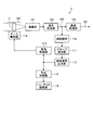
- FIG. 2 shows an exemplary configuration of the camera 1 according to each embodiment.
- the camera 1 includes an optical unit 100, an imaging unit 101, a signal processing unit 102, an image processing unit 103, a zoom driving unit 114, and a pan / tilt driving unit 116.
- the optical unit 100 includes an imaging lens 11 including one or more lenses, a lens driving mechanism that drives the imaging lens 11, and the like. Light from the subject enters the imaging lens 11 and is output to the imaging unit 101 via the optical unit 100.
- the imaging unit 101 includes an imaging element such as a CCD (Charge Coupled Device) or a CMOS (Complementary Metal Oxide Semiconductor) imager, and converts the light incident from the optical unit 100 into an electrical signal by photoelectric conversion and outputs the electrical signal.
- CCD Charge Coupled Device
- CMOS Complementary Metal Oxide Semiconductor
- the signal output from the imaging unit 101 according to the light incident on the imaging unit 101 is supplied to the signal processing unit 102.
- the signal processing unit 102 performs predetermined signal processing such as noise removal processing and gain adjustment processing on the signal supplied from the imaging unit 101, converts the signal into digital data by A / D conversion, and outputs the digital image as a captured image 120. This is supplied to the image processing unit 103 and a face recognition unit 110 described later.
- the signal processing unit 102 may be configured to be included in the imaging unit 101.
- the image processing unit 103 performs image processing such as white balance correction processing and gamma correction processing on the captured image 120 supplied from the signal processing unit 102, and outputs the processed image as an output image 121 to the outside of the camera 1.
- the present invention is not limited to this, and the camera 1 may be provided with storage means such as a memory, and the output image 121 output from the image processing unit 103 may be held in the memory.
- the zoom drive unit 114 controls the angle of view of the imaging lens 11 by driving a lens driving mechanism in accordance with an angle of view control signal from an angle of view control unit 113, which will be described later. ) To zoom in between.
- the pan / tilt driving unit 116 drives the horizontal rotation unit 21 and the vertical rotation unit 22 in accordance with a direction control signal from a direction control unit 115 described later to change the imaging direction of the imaging lens 11.
- the camera 1 further includes a face recognition unit 110, a group detection unit 111, a control signal output unit 112, an angle of view control unit 113, and a direction control unit 115.
- the face recognition unit 110 recognizes a face included in the captured image 120 supplied from the signal processing unit 102.
- the face recognition unit 110 can recognize a face included in the captured image 120 using a known method.
- the face recognition unit 110 may perform face recognition by detecting a face region and each facial organ from the captured image 120 by a subspace method using a face dictionary and pattern matching.
- the face recognition unit 110 further detects the direction in which the face recognized in the captured image 120 is facing.
- the face recognition unit 110 can detect the direction in which the face is facing based on the positional relationship between the face area of the recognized face and each facial organ (eyes, nose, mouth, etc.).
- the face recognition unit 110 outputs, for example, face position information indicating the position of each recognized face in the captured image 120 and face direction information indicating the direction of each face according to the face recognition result. In addition, the face recognition unit 110 outputs a captured image 120 on which face recognition has been performed. The face position information and face direction information output from the face recognition unit 110 and the captured image 120 are supplied to the group detection unit 111.
- the group detection unit 111 detects a group including a set of each face recognized in the captured image 120 based on the face position information and face direction information supplied from the face recognition unit 110 and the captured image 120.
- the group detection unit 111 supplies information on a set of faces included in the detected group and the captured image 120 to the control signal output unit 112.
- the control signal output unit 112 obtains the group direction with respect to the camera 1 based on the information of the face set included in the group and the captured image 120 supplied from the group detection unit 111. For example, based on each face included in the group, the group detection unit 111 obtains the barycentric position of the face of the group. For example, the control signal output unit 112 obtains the direction toward the obtained center of gravity from the imaging lens 11 of the camera 1 as the group direction, and outputs information indicating the direction.
- a virtual imaging surface 51 corresponding to a captured image captured by the camera 1 is considered, and the center of gravity position 50 is a point on the imaging surface 51.
- the virtual imaging surface 51 corresponds to, for example, an effective pixel area 202 described later with reference to FIG.
- a distance between the camera 1 and the imaging surface 51 is a distance D.
- the control signal output unit 112 acquires the angle of view ⁇ by the imaging lens 11 from the angle of view control unit 113 described later. Further, the control signal output unit 112 acquires distances L 1 and L 2 from the center of the captured image to the horizontal end and the center of gravity position on the imaging surface 51 from the captured image.
- control signal output unit 112 determines the position of the center of gravity of the camera 1 from the angle ⁇ which is a half of the angle of view ⁇ and the distances D, L 1 and L 2 according to the following equation (1).
- a direction angle ⁇ indicating the directed direction is obtained.
- the distance D is canceled out in the derivation process of the equation (1) and does not appear in the equation (1).
- ⁇ tan ⁇ 1 ⁇ (L 2 / L 1 ) tan ⁇ (1)
- control signal output unit 112 obtains the position of the center of gravity of the group as information indicating the direction of the group, this is an example, and the present invention is not limited to this example. That is, in practice, the control signal output unit 112 obtains information indicating the direction of each face constituting both ends of the group in the horizontal direction, and indicates the direction of the group together with information indicating the direction of the center of gravity position of the group. Output as information.
- the information indicating the direction of the group output from the control signal output unit 112 is supplied to the view angle control unit 113 and the direction control unit 115.
- the angle-of-view control unit 113 drives the zoom drive unit 114 according to the given information, and controls the angle of view by the imaging lens 11 to be a predetermined angle of view.
- the angle-of-view control unit 113 calculates the angle of view in accordance with the information indicating the group direction supplied from the control signal output unit 112. Then, the angle-of-view control unit 113 drives the zoom driving unit 114 to perform a zoom operation so that the angle of view by the imaging lens 11 becomes the calculated angle of view.
- the direction control unit 115 drives the pan / tilt driving unit 116 according to the given information to rotate the horizontal rotation unit 21 and the vertical rotation unit 22 so as to control the imaging direction of the camera 1 to be in a predetermined direction.
- the direction control unit 115 calculates the change amount of the imaging direction according to the information indicating the group direction supplied from the control signal output unit 112. Then, the direction control unit 115 drives the pan / tilt driving unit 116 to perform a pan operation so that the imaging direction of the camera 1 changes by the calculated change.
- the pan operation for changing the imaging direction in the horizontal direction and the tilt operation for changing the imaging direction in the vertical direction are collectively referred to as pan operation.
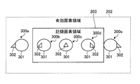
- FIG. 4 shows an example of an imaging region by the imaging device included in the imaging unit 101.
- the image sensor 200 includes, as pixel areas, a total pixel area 201 composed of all pixels on the image sensor 200, and an effective pixel area 202 that is an area that can be processed as an image signal in the total pixel area 201.
- an area outside the effective pixel area 202 is an area that cannot be used as an image signal output area such as an optical black area.
- the recording pixel area 203 is an image area that is processed as the output image 121 in the effective pixel area 202.
- an image signal corresponding to the entire effective pixel region 202 is output from the imaging unit 101.
- the signal processing unit 102 performs predetermined signal processing on the image signal supplied from the imaging unit 101 and outputs an image including all the pixels in the effective pixel region 202 as the captured image 120.
- the image processing unit 103 cuts out pixels in an area corresponding to the recording pixel area 203 from the captured image 120 supplied from the signal processing unit 102, and outputs it as an output image 121.
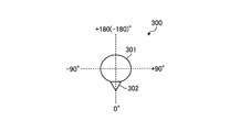
- FIG. 5 shows an example of face display according to the first embodiment.
- FIG. 5 shows a state in which the face 300 is viewed from directly above.
- the face 300 is simply indicated by a head 301 and a nose 302.
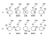
- FIG. 6 shows the definition of the face direction in the following description.
- FIG. 6A shows an example when the face is viewed from the camera 1 side.
- FIG. 6B shows an example of the direction when the face is viewed from directly above.
- the camera 1 is installed in the lower part of the drawing and the imaging lens 11 is directed upward.
- the orientation of the face is defined by the orientation of the nose 302 with respect to the head 301 as viewed from the camera 1.
- the face 300c faces the front.
- the face 300a of FIGS. 6A and 6B when the nose 302 is seen on the left side with respect to the head 301, it is assumed that the face 300a faces leftward, and the face 300b As shown in FIG. 5, when the nose 302 appears to be shifted to the left side in the head 301, it is assumed that the face 300b is directed obliquely to the left.
- the face 300a facing the left direction and the face 300b facing the left oblique direction are not distinguished, and the faces 300a and 300b are both treated as facing the left direction.
- FIG. 7 shows an example in which two faces are lined up, as seen from above.
- the faces 300c and 300c ′ face in directions 350 and 351 that are parallel to each other, the faces 300c and 300c ′ are not facing each other.
- the faces 300c and 300c ′ face the inner directions 352 and 353 with respect to the directions 350 and 351, the faces 300c and 300c ′ are assumed to face each other.
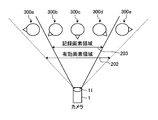
- the signal processing unit 102 obtains a captured image 120 of the effective pixel region 202 in the range of the angle of view by the imaging lens 11 from the image signal supplied from the imaging unit 101. As described above, in the captured image 120 by the effective pixel area 202, the recording pixel area 203 smaller than the effective pixel area 202 is cut out by the image processing in the image processing unit 103, and the image of the recording pixel area 203 is output as the output image. 121.
- the faces 300 a and 300 e are the targets of the face recognition process in the face recognition unit 110 and the group detection process in the group detection unit 111, like the faces 300b to 300d included in the recording pixel region 203.
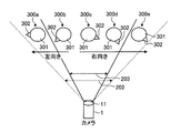
- FIG. 9 shows an example of a state in which each face 300a to 300e corresponding to the state of FIG. 8 is viewed from directly above.
- the horizontal region 202 of the effective pixel region 202 corresponds to the angle of view by the imaging lens 11 (optical unit 100) of the camera 1.
- the angle with respect to the imaging lens 11 is smaller than the angle of view.
- the group detection unit 11 detects a group to which a face belongs based on the direction and position of two adjacent faces. More specifically, the group detection unit 111 includes a set of faces including two faces facing each other among the faces recognized by the face recognition unit 110 from the captured image 120, that is, the effective pixel area 202. Are detected as a group.
- FIG. 10 and 11 show an example in which the faces 300a to 300e included in the effective pixel region 202 do not form a group according to the first embodiment.
- FIG. 10 is an example in which each of the faces 300a to 300e included in the effective pixel area 202 is directed to the left. In this case, since there is no set of faces facing each other in the faces 300a to 300e, the group detection unit 111 determines that no group exists.
- FIG. 11 is an example in which each face 300a to 300e included in the effective pixel region 202 has faces facing in different directions, and each face 300a to 300e does not form a group.
- the faces 300a and 300b face left, the faces 300c to 300e face right, and there is no face pair facing each other, so the group detection unit 111 determines that no group exists. To do.
- FIG. 12 shows an example in which the faces 300a to 300e included in the effective pixel area 202 form a group according to the first embodiment.
- the group detection unit 111 has a face 300b facing right and a face 300c adjacent to the face 300b facing left based on the face position information and face direction information supplied from the face recognition unit 110. It is determined that 300b and 300c face in the direction facing each other. Therefore, the group detection unit 111 detects the group 310a having the faces 300b and 300c as both ends. Furthermore, based on the face position information and the face direction information, the group detection unit 111 faces the face 300d to the right, the face 300e adjacent to the face 300d to the left, and the faces 300d and 300e to face each other. It is determined that Therefore, the group detection unit 111 detects the group 310b having the faces 300d and 300e as both ends.
- the group detecting unit 111 faces the left side, the face 300b adjacent to the face 300a faces the right side, and faces the direction where the faces 300a and 300b face each other. It is determined that no group is formed. Similarly, in the group detection unit 111, the face 300c faces left, the face 300d adjacent to the face 300c faces right, the faces 300c and 303d do not face each other, and no group is formed. Is determined.
- a face facing the front with respect to the camera 1 like the face 300c in FIG. 9 does not constitute the end of the group. Further, there may be a case where the face cannot be detected because the face is directed upward, downward or rearward with respect to the camera 1. In such a case, since the face is not detected in the first place, the face in these states does not constitute the end of the group.
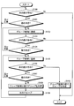
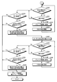
- FIG. 13 is a flowchart illustrating an example of group detection processing by the group detection unit 111 according to the first embodiment.
- the process according to the flowchart of FIG. 13 is repeatedly executed at a predetermined interval, for example, an interval of the frame period of the captured image 120.
- the group detection unit 111 detects the group by sequentially determining the direction of each face from one end in the horizontal direction in the effective pixel region 202 toward the other end.
- the group detection unit 111 determines the orientation of each face from the left end to the right end of the effective pixel region 202.
- step S100 the group detection unit 111 determines whether or not the next face exists to the right of the face currently determined. In the case of the first process for the effective pixel area 202, the group detection unit 111 determines whether or not a face exists in the effective pixel area 202. When the group detection unit 111 determines that the next face does not exist, the group detection unit 111 ends the series of processes in the flowchart of FIG.
- step S100 the group detection unit 111 sets the next face as a target face and shifts the processing to step S101.
- step S101 the group detection unit 111 determines the orientation of the target face. If the group detection unit 111 determines that the orientation of the target face is left or front, the process returns to step S100.
- step S101 determines in step S101 that the orientation of the target face is rightward
- step S102 shifts the processing to step S102 and registers the target face as a group candidate.
- step S103 the group detection unit 111 determines whether or not the next face exists to the right of the target face.
- the group detection unit 111 ends a series of processes according to the flowchart of FIG. In this case, the group candidate whose face is registered in step S102 is discarded.
- step S103 the group detection unit 111 sets the next face as a new target face, and shifts the processing to step S104.
- step S104 the group detection unit 111 determines the orientation of the target face. If the group detection unit 111 determines that the orientation of the target face is right or front, the process returns to step S102, and the target face is additionally registered as a group candidate.
- step S104 When the group detection unit 111 determines in step S104 that the target face is facing left, the group detection unit 111 shifts the process to step S105 and additionally registers the target face as a group candidate.
- step S106 the group detection unit 111 determines whether or not the next face exists to the right of the target face. If the group detection unit 111 determines that the next face does not exist, the group detection unit 111 shifts the processing to step S110 and forms a group with the faces registered in the group candidates. Then, a series of processes according to the flowchart of FIG.
- step S106 When the group detection unit 111 determines in step S106 that the next face exists, the group detection unit 111 sets the next face as a new target face, and shifts the processing to step S107. In step S107, the group detection unit 111 determines the orientation of the target face. If the group detection unit 111 determines that the orientation of the target face is left or front, the process returns to step S105, and the target face is additionally registered as a group candidate.
- the group detection unit 111 determines in step S107 that the orientation of the target face is rightward, the group detection unit 111 shifts the process to step S108, and forms a group with the faces registered in the group candidates. At this time, the group detection unit 111 gives identification information for identifying the group to the formed group.
- the identification information is a group number whose value is incremented from “1”.
- step S109 the group detection unit 111 increments the group number, for example, by 1, and prepares the next group detection process. Then, the group detection unit 111 returns the process to step S100, and determines whether or not the next face exists to the right of the face determined to exist in step S106.
- the group detection unit 111 can detect a group corresponding to a change in face orientation by repeatedly executing the processing according to the flowchart of FIG. 13 at predetermined time intervals. For example, when the face 300e changes to the right from the state of FIG. 12 described above, the group detection unit 111 detects a group of the faces 300a to 300e with the face 300e facing to the right. In this case, since both the faces 300d and 300e constituting the group 310b face rightward, the group 310b disappears. Therefore, the group detection unit 111 detects only the group 310a of the faces 300b and 300c according to the flowchart of FIG.
- the group detection unit 111 detects a group of the faces 300a to 300e with the face 300d facing left. That is, as illustrated in FIG. 14, when the face 300d faces left, the faces 300b and 300d face each other. Therefore, the group 310a formed by the faces 300b and 300c is expanded, and the faces 300b and 300d A group 310a ′ including a set of faces having both ends at 300d is formed. Therefore, the group detection unit 111 detects the group 310a ′ of the faces 300b, 300c, and 300d according to the flowchart of FIG.
- Imaging operation focusing on groups Next, an imaging operation focusing on groups according to the first embodiment will be described.
- imaging focusing on the group detected by the group detection unit 111 is performed by a zoom operation, a pan operation, or the like.
- the faces 300b and 300c among the faces 300a to 300e form a group 310c.
- the group 310c (faces 300b and 300c) and the face 300d are included in the recording pixel area 203, and the faces 300a to 300e are included in the effective pixel area 202.
- the camera 1 pans the camera 1 in the direction of the group 310c and zooms the lens 11 to the tele end side, so that the recording pixel area 203 displays the faces 300b and 300c. Imaging is performed so as not to include the included face 300d. Thereby, the camera 1 can obtain the output image 121 in which the group 310c, that is, the faces 300b and 300c is noticed.
- the camera 1 may perform the zoom operation and the pan operation so that the face 300b and the face 300c are within the angle of view, and the width of the face is considered in consideration of the vertical and horizontal widths of each face.
- the angle of view and the imaging direction may be set so as to have a predetermined ratio with respect to the recording pixel area 203.
- the camera 1 can shoot groups with various compositions such as a zoomed face image and a bust-up image.
- FIG. 17 is a flowchart illustrating an example of an imaging operation focusing on a group according to the first embodiment.
- the group detection unit 111 detects all groups included in the captured image 120, that is, the effective pixel region 202, according to the flowchart of FIG.
- the control signal output unit 112 outputs a control signal for panning so that the center of gravity of all groups detected in step S 120 is positioned at the center of the output image 121, that is, the recording pixel region 203.
- the direction control unit 115 controls the pan / tilt driving unit 116 according to the control signal to change the imaging direction of the camera 1.
- the center of gravity of a group is a value obtained by averaging the relative positions of each face included in the group.
- the center of gravity of all groups is a value obtained by averaging the centers of gravity of each group.
- the control signal output unit 112 determines whether the imaging mode of the camera 1 is the collective mode or the individual mode.
- the collective mode is an operation mode for collectively capturing all groups included in the captured image 120.
- the individual mode is an operation mode for capturing all groups included in the captured image 120 for each group. Note that the camera 1 can set the imaging mode in accordance with, for example, a user operation on an operation unit (not shown).
- step S122 When the control signal output unit 112 determines in step S122 that the operation mode of the camera 1 is the batch mode, the control signal output unit 112 shifts the process to step S123.
- step S123 the control signal output unit 112 determines the position of the leftmost face included in the leftmost group in all groups and the position of both ends in all groups configured by the rightmost face included in the rightmost group. Based on the angle of view by the imaging lens 11, it is determined whether or not all groups fit within the image, that is, within the recording pixel region 203 by the zoom operation.
- the control signal output unit 112 acquires the angle of view ⁇ when the imaging lens 11 is zoomed to the wide-angle end, and the positions on the virtual imaging surface 51 at both end positions in all groups, and the above-described formula ( It is conceivable to make the determination in step S123 based on 1).
- the control signal output unit 112 uses the position of the optical axis of the imaging lens 11 on the imaging surface 51 as a reference, and determines the distance from the optical axis of the face farther from the optical axis of the imaging lens 11 among the faces.
- the angle ⁇ is obtained from the above equation (1).
- the control signal output unit 112 determines whether or not all the groups fit in the image, that is, the recording pixel region 203 based on the result of comparing the angle ⁇ and the angle ( ⁇ / 2).
- step S123 When the control signal output unit 112 determines in step S123 that all groups are within the recording pixel area 203 when the angle of view of the imaging lens 11 is widened to a predetermined angle of view, for example, the wide angle end by zooming, the process is performed. The process proceeds to step S124.
- step S ⁇ b> 124 the control signal output unit 112 outputs a control signal for performing a zoom operation so that all the groups are within the image, that is, within the recording pixel region 203, and supplies the control signal to the view angle control unit 113. Then, a series of processes according to the flowchart of FIG.
- control signal output unit 112 generates a control signal for driving the imaging lens 11 so as to widen it to a predetermined angle of view.
- control signal output unit 112 may generate a control signal for controlling the angle of view of the imaging lens 11 based on the angle ⁇ obtained using the equation (1) in step S123 described above.
- step S123 If the control signal output unit 112 determines in step S123 that the entire group does not fit within the recording pixel area 203 when the angle of view of the imaging lens 11 is expanded to a predetermined angle of view by zooming, the process proceeds to step S125. Transition. In step S125, the control signal output unit 112 outputs a control signal for zooming the imaging lens 11 to a predetermined angle of view, for example, the wide angle end, and for panning the camera 1 for each group. 113 and the direction control unit 115.
- FIG. 18 shows an example in which two groups of the group 310d and the group 310e are formed in a relatively close distance in the effective pixel region 202.
- the camera 1 zooms the imaging lens 11 to, for example, the wide-angle end, and pans toward the center of gravity of the groups 310d and 310e, thereby including the groups 310d and 310e in the recording pixel region 203. be able to.
- control signal output unit 112 generates, for example, a control signal for performing a zoom operation at the wide angle end and supplies the control signal to the angle of view control unit 113.
- control signal output unit 112 generates a control signal for panning toward the center of gravity of the groups 310 d and 310 e and supplies the control signal to the direction control unit 115.
- FIG. 19 shows an example in which two groups 310 f and 310 g are formed at a relatively far distance in the effective pixel region 202.
- the camera 1 zooms the imaging lens 11 to, for example, the wide-angle end and pans toward the center of gravity of the groups 310f and 310g, a part of the groups 310f and 310g is recorded. It protrudes from the pixel region 203.
- the camera 1 zooms the imaging lens 11 to the wide-angle end, for example, and first pans toward the center of gravity of the group 310f, for example.
- the camera 1 pans toward the center of gravity of the group 310g while zooming the imaging lens 11 to the wide angle end, for example.
- the groups 310f and 310g can be sequentially included in the recording pixel region 203.
- control signal output unit 112 first generates, for example, a control signal for performing a zoom operation at the wide angle end and supplies the control signal to the view angle control unit 113, and performs a pan operation toward the center of gravity of the group 310f.
- a control signal is generated and supplied to the direction control unit 115.
- the control signal output unit 112 After a predetermined time of the pan operation, the control signal output unit 112 generates a control signal for performing the pan operation toward the center of gravity of the group 310g and supplies the control signal to the direction control unit 115.
- step S122 when the control signal output unit 112 determines that the operation mode of the camera 1 is the individual mode, the process proceeds to step S126.
- step S126 the control signal output unit 112 generates a control signal for panning the camera 1 for each group and for zooming the imaging lens 11 to the tele end side for each group. This is supplied to the view angle control unit 113.
- FIG. 20 shows an example in which a pan operation and a zoom operation are performed for each group in step S126.
- a group 310f is formed by faces 300b 'and 300c'
- a group 310g is formed by faces 300d 'and 300e' on the right side of the group 310f.
- the control signal output unit 112 When performing the pan operation in order from the left group, the control signal output unit 112 first obtains the direction of the center of gravity of the group 310f and on the virtual imaging surface 51 of the faces 300b ′ and 300c ′ included in the group 310f. Each position (position in the effective pixel area 202) is obtained, and each obtained position is located at, for example, both ends of the recording pixel area 203 (actually, each position considering the contours of the faces 300b ′ and 300c ′). The angle of view ⁇ 1 is calculated.
- the angle of view ⁇ 1 is, for example, the current angle of view ⁇ and the positions of the faces 300b ′ and 300c ′ on the imaging surface 51 and the imaging surfaces 51 of the faces 300b ′ and 300c ′ after zooming to the tele end. Can be calculated using the above-described equation (1).
- the control signal output unit 112 generates a control signal for panning in the direction of the center of gravity of the group 310f and supplies the control signal to the direction control unit 115. At the same time, a control signal for changing the angle of view of the imaging lens 11 to the calculated angle of view ⁇ 1 is generated and supplied to the angle of view control unit 113.
- the control signal output unit 112 obtains the direction of the center of gravity of the group 310g in the same manner as described above after a predetermined time after the pan operation and the zoom operation are performed according to the control signals by the direction control unit 115 and the view angle control unit 113, respectively. An angle of view ⁇ 2 for zooming with respect to 300d ′ and 300e ′ is calculated. Then, the control signal output unit 112 changes the direction of the center of gravity of the group 310g generates a control signal for causing the pan operation is supplied to the direction control unit 115, the angle gamma 2 calculated the angle of view of the imaging lens 11 A control signal for generating the image is generated and supplied to the view angle control unit 113.
- step S126 when the pan operation and the zoom operation are performed on all the groups included in the effective pixel area 202, a series of processes according to the flowchart of FIG. Not limited to this, the camera 1 may repeat the pan operation and the zoom operation for each group included in the effective pixel region 202.
- This phenomenon can be suppressed, for example, by applying a low-pass filter process to the execution timing of each operation in steps S124, S125, and S126 in FIG. That is, the low-pass filter process suppresses the reaction of each operation to a change in the face direction for a short time, and can realize a calm display.
- each face included in the captured image 120 can be appropriately grouped.
- panning and zooming operations can be performed according to the grouping result of each face, it is possible to focus on mutually related faces in the captured image 120 including a plurality of faces.
- a group is formed by determining the face orientation in order from either the left or right end of the effective pixel region 202.
- a group including the face designated as the target among the faces included in the effective pixel region 202 is formed.
- the face 320 is designated as a group formation target.
- the face 320 is referred to as a target 320.
- a group 321 (referred to as a target affiliation group 321) including a target 320 and a face facing the target 320 is formed. At this time, it does not matter whether the target 320 is facing left, diagonally left, front, diagonally right, or right.
- the target 320 is located at the center of each face included in the effective pixel region 202.
- the face 300 a located on the left side of the target 320 is leftward and does not face the target 320, and is not included in the target affiliation group 321.
- the face 300 b located on the left side of the target 320 faces rightward and faces the target 320, and is included in the target affiliation group 321.
- the faces 300d and 300e located on the right side of the target 320 are each facing left and facing the target 320, and are included in the target affiliation group 321.
- zoom operation and pan operation for the target affiliation group 321 are the same as those in the first embodiment described above, and thus the description thereof is omitted here.
- any of the faces in the effective pixel region 202 is designated as the target 320 to the group detection unit 111.
- the target 320 it may be possible to specify the target 320 by a user operation on an operation unit (not shown) provided in the camera 1.
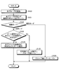
- the processing according to the flowcharts of FIGS. 22 to 25 is repeatedly executed at a predetermined interval, for example, an interval of the frame period of the captured image 120.
- step S200 the group detection unit 111 first registers the face of the target 320 as a group candidate.
- the group detection unit 111 sets the face of the target 320 as the face of interest.
- step S202 the group detection unit 111 determines whether the face direction of the target 320 is leftward, frontward, or rightward. When the group detection unit 111 determines in step S202 that the face direction of the target 320 is the front direction, the group detection unit 111 shifts the process to the process according to the flowchart of FIG.
- step S210 the group detection unit 111 determines whether a face exists to the left of the face of interest. If it is determined that it exists, the group detection unit 111 shifts the processing to step S211 and determines the orientation of the face that exists to the left of the face of interest. When the group detection unit 111 determines that the face existing to the left of the face of interest is facing either the right side or the front side, the group detection unit 111 shifts the processing to step S212, and the face existing to the left of the face of interest is grouped. Register as a candidate. Then, in the next step S213, the group detection unit 111 updates the attention face with the face existing on the left of the attention face as a new attention face. Then, the process returns to step S210.
- step S210 determines in step S210 described above that there is no face to the left of the target face, or in step S211 described above, the face existing to the left of the target face turns to the left. If it is determined that it is, the process proceeds to step S214.
- step S ⁇ b> 214 the group detection unit 111 determines whether a face exists on the left side of the face of the target 320. If it is determined that there is a face to the left of the face of the target 320, the group detection unit 111 shifts the processing to step S215.
- step S215 the group detection unit 111 determines whether a right-facing face is registered as a group candidate. If it is determined that the face is registered, the process proceeds to step S216.
- step S214 determines in step S214 that there is no face to the left of the face of the target 320, or if it is determined in step S215 that a right-facing face is not registered in the group candidate. The process proceeds to step S226.
- step S226 the group detection unit 111 deletes faces other than the face of the target 320 from the faces registered as group candidates. As a result, only the face of the target 320 is registered in the group candidate.
- the group detection unit 111 shifts the process to step S225 described later.
- step S216 the group detection unit 111 deletes the registration on the left side of the face facing to the left among the faces registered in the group candidates. As a result, among the faces registered in the group candidates, the front facing face is deleted from the left end side, and the right facing face is registered at the left end of the group candidate.
- the group detection unit 111 shifts the process to step S217, and sets the face of the target 320 as the target face again.
- step S218 the group detection unit 111 determines whether a face exists on the right side of the face of interest. If it is determined that it exists, the group detection unit 111 shifts the processing to step S219, and determines the orientation of the face that exists to the right of the face of interest.
- the group detection unit 111 determines that the face existing to the right of the target face is facing either the left side or the front side
- the group detection unit 111 shifts the processing to step S220, and the face existing to the right side of the target face is grouped. Register as a candidate.
- the group detection unit 111 updates the attention face with the face existing on the right of the attention face as a new attention face. Then, the process returns to step S218.
- step S218 the group detection unit 111 determines in step S218 described above that there is no face to the right of the target face, or in step S219 described above, the face that exists to the right of the target face turns to the right. If it is determined that it is, the process proceeds to step S222.
- step S222 the group detection unit 111 determines whether a face exists to the right of the face of the target 320. If it is determined that there is a face to the right of the face of the target 320, the group detection unit 111 shifts the processing to step S223. In step S223, the group detection unit 111 determines whether a left-facing face is registered as a group candidate. If it is determined that the face is registered, the process proceeds to step S224.
- the group detection unit 111 determines in step S222 that there is no face to the right of the face of the target 320, or determines in step S223 that no left-facing face is registered in the group candidate on the right side of the target. If so, the process proceeds to step S226, and faces other than the face of the target 320 are deleted from the faces registered as group candidates.
- step S224 the group detection unit 111 deletes the registration of the face on the right side from the left-facing face located at the rightmost among the faces registered in the group candidates.
- the front facing face is deleted from the right end side, and the left facing face is registered at the right end of the group candidate.
- the group detection unit 111 configures a group with faces registered as group candidates. Then, a series of processes in the case where the target 320 faces the front according to FIG.
- step S202 of the flowchart of FIG. 22 described above when the group detection unit 111 determines that the face of the target 320 is facing left, the group detection unit 111 shifts the process to the process of the flowchart of FIG.
- the process according to the flowchart of FIG. 24 is a process obtained by removing the process of step S226 from the process according to the flowchart of FIG. That is, in step S240, the group detection unit 111 determines whether or not there is a face to the left of the face of interest. If it is determined that the face is present, in step S241, the group detection unit 111 Determine the orientation. If the group detection unit 111 determines that the face existing to the left of the face of interest is facing either the right side or the front side, the group detection unit 111 shifts the processing to step S242 to group the face existing to the left of the face of interest. Register as a candidate. Then, in the next step S243, the group detection unit 111 updates the attention face with the face existing on the left of the attention face as a new attention face, and returns the process to step S240.
- the group detection unit 111 determines that there is no face to the left of the face of interest in step S240 described above, or the face existing to the left of the face of interest faces left in step S241 described above. If it is determined that the face is present, the process proceeds to step S244, and it is determined whether or not a face is present to the left of the face of the target 320. If it is determined that the group exists, the group detection unit 111 shifts the process to step S245, determines whether or not a right-facing face is registered as a group candidate, and if it is determined that the face is registered, the process proceeds to step S246. To migrate. In step S246, the group detection unit 111 deletes the registration of the face on the left side of the face facing rightmost among the faces registered in the group candidates.
- step S244 determines in step S244 that there is no face to the left of the face of the target 320, or if it is determined in step S245 that a right-facing face is not registered in the group candidate. The process proceeds to step S255 described later.
- the group detection unit 111 shifts the process to step S247, and sets the face of the target 320 as the face of interest again. Then, in the next step S248, the group detection unit 111 determines whether or not there is a face to the right of the face of interest. If it is determined that the face exists, the group detection unit 111 proceeds to the next step S249 and proceeds to the right of the face of interest. Determine the orientation of the face that exists. If the group detection unit 111 determines that the face existing to the right of the target face is facing either the left side or the front side, the group detection unit 111 shifts the processing to step S250, and the face existing to the right side of the target face is grouped. Register as a candidate. Then, in the next step S251, the group detection unit 111 updates the attention face with the face existing on the right of the attention face as a new attention face, and returns the process to step S248.
- step S248 determines in step S248 described above that there is no face to the right of the face of interest, or in step S249 described above, the face existing to the right of the face of interest turns to the right. If it is determined that the process has been performed, the process proceeds to step S252.
- step S252 the group detection unit 111 determines whether a face exists to the right of the face of the target 320. If it is determined that the face exists, the group detection unit 111 shifts the processing to step S253.
- step S253 the group detection unit 111 determines whether a left-facing face is registered as a group candidate. If it is determined that the face is registered, the process proceeds to step S254. In step S254, the group detection unit 111 deletes the registration of the face on the right side of the face facing leftmost among the faces registered in the group candidates.
- the group detection unit 111 configures a group with faces registered as group candidates. Then, a series of processes in the case where the target 320 is facing left is finished according to FIG.
- step S260 the group detection unit 111 determines whether or not there is a face to the right of the face of interest. If it is determined that the face is present, in step S261, the group detection unit 111 Determine the orientation. If the group detection unit 111 determines that the face existing to the right of the target face is facing either the left side or the front side, the group detection unit 111 shifts the processing to step S262, and the face existing to the right side of the target face is grouped. Register as a candidate. Then, in the next step S263, the group detection unit 111 updates the attention face with the face existing on the right of the attention face as a new attention face, and the process returns to step S260.
- the group detection unit 111 determines in step S260 described above that there is no face to the right of the face of interest, or in step S261 described above, the face present to the right of the face of interest turns to the right. If it is determined that the face is present, the process proceeds to step S264, and it is determined whether or not a face exists to the right of the face of the target 320. If it is determined that there is a group, the group detection unit 111 shifts the process to step S265, determines whether a left-facing face is registered as a group candidate, and if it is determined that the face is registered, the process proceeds to step S266. To migrate. In step S266, the group detection unit 111 deletes the registration of the face on the right side of the face facing leftmost among the faces registered in the group candidates.
- step S264 determines in step S264 that there is no face to the right of the face of the target 320, or if it is determined in step S265 that a left-facing face is not registered in the group candidate. The process proceeds to step S275 described later.
- step S266 the group detection unit 111 shifts the process to step S267, and sets the face of the target 320 as the target face again. Then, in the next step S268, the group detection unit 111 determines whether or not there is a face to the left of the face of interest. If it is determined that the face exists, the group detection unit 111 proceeds to the next step S269 and moves to the left of the face of interest. Determine the orientation of the face that exists. If the group detection unit 111 determines that the face existing to the left of the face of interest is facing either the right side or the front side, the group detection unit 111 shifts the processing to step S270 to group the face existing to the left of the face of interest. Register as a candidate. In next step S271, the group detection unit 111 updates the attention face with the face existing on the left of the attention face as a new attention face, and the process returns to step S268.
- step S268 determines in step S268 above that there is no face to the left of the target face, or in step S269 described above, the face existing to the left of the target face turns to the left. If it is determined that it is, the process proceeds to step S272.
- step S272 the group detection unit 111 determines whether or not there is a face to the left of the face of the target 320. If it is determined that the face exists, the process proceeds to step S273.
- step S273 the group detection unit 111 determines whether a right-facing face is registered as a group candidate. If it is determined that the face is registered, the process proceeds to step S274. In step S274, the group detection unit 111 deletes the registration of the face on the left side of the right-facing face that is positioned at the leftmost among the faces registered in the group candidates.
- the group detection unit 111 forms a group with the faces registered in the group candidates. Then, a series of processes in the case where the target 320 is facing the right according to FIG. 24 is ended.
- FIG. 26 is a flowchart illustrating an example of an imaging operation focusing on a group including a target face according to the second embodiment.
- step S150 any of the faces in the effective pixel region 202 is designated as a target for the group detection unit 111.
- the group detection unit 111 forms a target affiliation group including the target according to the process according to the flowchart of FIG.
- the group detection unit 111 detects all the groups formed by the faces included in the effective pixel area 202 in accordance with the processing according to the flowchart of FIG. At this time, the group detection unit 111 forms a group by excluding the faces included in the target affiliation group among the faces included in the effective pixel region 202.
- control signal output unit 112 outputs a control signal for panning so that the center of gravity of the target group detected in step S151 is located at the center of the output image 121, that is, the recording pixel region 203.
- the direction control unit 115 controls the pan / tilt driving unit 116 according to the control signal to change the imaging direction of the camera 1.
- step S154 the control signal output unit 112 determines whether the imaging mode of the camera 1 is the batch mode or the individual mode. If the control signal output unit 112 determines in step S154 that the operation mode of the camera 1 is the batch mode, the control signal output unit 112 shifts the process to step S155. In step S155, the control signal output unit 112 determines whether or not the target group belongs within the image, that is, within the recording pixel region 203 by the zoom operation. This determination can be performed in the same procedure as the process of step S123 in the flowchart of FIG.
- step S155 When the control signal output unit 112 determines in step S155 that the target group belongs within the recording pixel area 203 by the zoom operation, the process proceeds to step S156.
- step S 156 the control signal output unit 112 outputs a control signal for performing a zoom operation so that the target group belongs within the image, that is, within the recording pixel region 203, and supplies the control signal to the angle of view control unit 113. Then, a series of processes according to the flowchart of FIG.
- step S155 If the control signal output unit 112 determines in step S155 that the target group does not fit in the recording pixel area 203 by the zoom operation, the process proceeds to step S157.
- step S157 the control signal output unit 112 outputs a control signal for zooming the imaging lens 11 to, for example, the wide-angle end and panning the camera 1 so as to image the target group. This is supplied to the control unit 113 and the direction control unit 115. Then, a series of processes according to the flowchart of FIG.
- step S157 the camera 1 may perform a zoom operation so that the face of the target 320 is captured with an appropriate size instead of performing panning within the target group.
- step S154 When the control signal output unit 112 determines in step S154 that the operation mode of the camera 1 is the individual mode, the control signal output unit 112 shifts the process to step S158.
- step S158 the control signal output unit 112 determines whether or not the target group belongs within the image, that is, within the recording pixel region 203 by the zoom operation.
- step S158 When the control signal output unit 112 determines in step S158 that the target group belongs within the recording pixel area 203 by the zoom operation, the control signal output unit 112 shifts the process to step S159.
- step S159 the control signal output unit 112 zooms the imaging lens 11 so that the target group belongs within the image, that is, within the recording pixel region 203, and the camera 1 is set for every group including the target group.
- a control signal for panning is output and supplied to the angle of view control unit 113 and the direction control unit 115. Then, a series of processes according to the flowchart of FIG.
- the camera 1 can make the target belonging group more conspicuous in the captured image 120 by performing the imaging of the target belonging group by an operation different from the imaging operation of the other groups.
- an imaging operation only when the target group is imaged, the imaging lens 11 is imaged for a longer time than the other groups. It is conceivable to perform panning operation slower than other groups and take an image.
- step S158 When the control signal output unit 112 determines in step S158 that the target affiliation group does not fit in the recording pixel area 203 by the zoom operation, the control signal output unit 112 shifts the processing to step S160.
- step S160 the control signal output unit 112 outputs a control signal for zooming the imaging lens 11 to, for example, the wide-angle end and panning the camera 1 in the target group, and the angle-of-view control unit 113 and This is supplied to the direction control unit 115.
- the control signal output unit 112 outputs a control signal for performing the pan operation for each group and supplies the control signal to the direction control unit 115. Then, a series of processes according to the flowchart of FIG.
- step S160 the camera 1 may perform a zoom operation so that the face of the target 320 is captured with an appropriate size instead of performing panning within the target group.
- step S160 when the camera 1 performs a pan operation within the target affiliation group, the target face can be made more conspicuous by performing imaging of the target face by an operation different from the imaging operation of other faces.
- an imaging operation only when the target face is imaged, an image is taken for a longer time than the other face, and the imaging lens 11 is zoomed to the tele end side than the other face to image up. It may be possible to output a control signal such as performing a panning operation more slowly than other faces, and imaging the target face with a camera operation different from that of other faces.
- the camera 1 can designate not only one target face but also a plurality of target faces.
- the camera 1 performs an imaging operation that makes the target group noticeable for the plurality of groups to which the face of each target belongs. Also good.
- the camera 1 performs an imaging operation to make the target face stand out for each target face when panning the group. It may be.
- the second embodiment it is possible to form a group including a target face designated from each face included in the captured image 120. Therefore, since the pan operation and the zoom operation can be selectively performed on the group including the target face, the degree of attention of the group including the target face can be increased.
- each face included in the effective pixel region 202 is described as being linearly arranged on a plane substantially perpendicular to the optical axis of the camera 1. did.
- the face included in the effective pixel area 202 is two-dimensionally arranged on a plane substantially parallel to the optical axis of the camera 1 in a horizontal direction, that is, having a planar spread. It is an example of group formation when
- each face is arranged in the vertical direction of the image according to the distance from the camera 1.
- FIG. 27 shows an example of grouping according to the third embodiment.
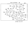
- the face recognition unit 110 recognizes the faces 300h to 300s in the effective pixel area 202, face position information indicating the positions of the faces 300h to 300s in the effective pixel area 202, and the faces 300h to 300s. Is output to the group detection unit 111. Further, the face recognition unit 110 acquires the size of each face 300h to 300s on the image during the recognition process of each face 300h to 300s in the effective pixel region 202. Then, the face recognition unit 110 supplies face size information indicating the size of each of the acquired faces 300h to 300s to the group detection unit 111.
- the group detection unit 111 groups the faces 300h to 300s existing in the effective pixel region 202 based on the face position information and face size information supplied from the face recognition unit 110.
- the group detection unit 111 obtains a distance between the faces 300h to 300s based on the face position information, and forms a group of faces having a close distance. For example, the group detection unit 111 obtains the distance between adjacent faces for each of the faces 300h to 300s. When the distance between each face 300h to 300s and the adjacent face is obtained, the group detection unit 111 sets a threshold based on the obtained distance, and each face 300h to 300s is compared with each other face. Each distance is obtained, and faces whose distance is within the threshold are sequentially extracted to form a group.
- a group formed based on the size and distance of each face 300h to 300s included in the effective pixel region 202 is referred to as a provisional group.
- the group detection unit 111 obtains the distances of the face 300h from the other faces 300i to 300s, and extracts faces whose distances are within the threshold.
- the face 300i is a face whose distance from the face 300h is within a threshold value.
- the group detection unit 111 obtains the distance between the face 300i and each of the other faces 300j to 300s excluding the face 300h, and extracts a face whose distance is within the threshold.
- the face 300j is a face whose distance from the face 300i is within a threshold value.
- the group detection unit 111 obtains the distance between the face 300j and each of the other faces 300k to 300s excluding the faces 300h and 300i, and extracts a face whose distance is within the threshold. For example, when a face whose distance is within the threshold with respect to the face 300j cannot be extracted, the group detection unit 111 forms a temporary group 330a with the faces 300h to 300j whose distance is within the threshold, and starts from the next face, for example, the face 300k.
- the provisional group 330b is formed based on the distance of other faces.
- the group detection unit 111 performs the formation of the provisional group 330c in the same manner.
- the group detection unit 111 performs provisional group formation based on the distance for each face 300 k to 300 s in the effective pixel region 202. In the example of FIG. 27, it is assumed that three provisional groups 330a to 330c are formed in the effective pixel region 202.
- the group detection unit 111 can perform group classification based on the face size information of each face 300h to 300s. For example, the group detection unit 111 obtains a size distribution of each face 300h to 300s based on the face size information, and classifies faces having similar sizes into groups from the obtained distribution.
- the effective pixel area 202 includes a plurality of faces 300 h to 300 s, and the size of each face 300 h to 300 s is larger below the effective pixel area 202 closer to the camera 1 and farther from the camera 1. It can be seen that it is smaller on the upper side of the effective pixel region 202.
- FIG. 28 shows an example of face size distribution in the face arrangement of the example of FIG. 27 in association with the positions of the faces 300h to 300s.
- the vertical axis indicates the size of the face in the effective pixel region 202, and the size of the face decreases in the direction of the arrow.
- the horizontal axis indicates the arrangement of the faces 300h to 300s in the effective pixel region 202, with the indexes h to s corresponding to the faces 300h to 300s, respectively.
- the shape of the group based on the position of the face is often arranged in a substantially circular shape or a substantially arc shape as shown in FIG.
- this group is imaged with the camera 1 in a bird's-eye view
- the size of the face in the captured image 120 is the largest in the back (backward) face located on the near side of the group as viewed from the camera 1.
- the faces at both ends then become larger, and the face at the back of the group becomes the smallest.
- the face behind the head is ignored and the size distribution of the faces located at both ends and back of the group is considered.
- the shape of the group is a substantially circular shape or a substantially arc shape
- the face on the back side of the group is smaller than the faces on both ends, and the distribution of the face size is as shown by the broken lines in FIG.
- the distribution is an upward convex bow shape. That is, the possibility that the size of the face in the central part of the group is larger than the size of the faces at both ends of the group is small.
- Each face 300h to 300s can be classified into groups based on the distribution of face sizes in the group.
- the group classification of the face performed by the group detection unit 111 is not limited to the method performed based on the distribution of the bow shape.
- the group detection unit 111 can classify the face into a group in the captured image 120 that is directly above the group and in a positional relationship facing the face.
- the group detection unit 111 detects whether or not the size of the face is distributed in an upward convex bow shape, thereby improving the classification accuracy of the provisional group. it can.
- the group detection unit 111 forms a group of faces for each of the formed temporary groups 330a to 330c in the same manner as in the first embodiment or the second embodiment described above.
- the provisional group 330c includes five faces 300o to 300s. Of the faces 300o to 300s, the faces 300r and 300s are faces facing obliquely behind the camera 1. Even in this case, if the nose 302 is detected in the faces 300r and 300s, You can get the direction.
- the group detection unit 111 may form a group based on the orientation of any face belonging to the provisional group. it can. At this time, it is conceivable that the group detection unit 111 performs face orientation determination in an order corresponding to the horizontal position of each face in the effective pixel region 202. In the example of FIG. 27, the faces 300o, 300p, and 300s are facing right, and the faces 300q and 300r are facing left, respectively.
- the group forming method of the first embodiment assuming that group formation is performed from the leftmost face 300o of the temporary group 330c, for example, according to the flowchart of FIG. It is formed.
- the group detection unit 111 may form a group based on the center of gravity of each face belonging to the provisional group. That is, the group detection unit 111 forms a group with faces facing the direction of the center of gravity among the faces belonging to the provisional group.
- the control signal output unit 112 can perform the pan operation and the zoom operation for each group as described above for the group formed in this way according to the third embodiment.
- the group detection unit 111 may exclude a face facing backward or obliquely backward, such as the faces 300r and 300s, from the group formation determination. That is, even if a person who is looking backward or obliquely backward is picked up by, for example, panning and zooming, only the back of the head is picked up and the priority is considered low.
- each face according to the above-described third embodiment is arranged with a two-dimensional spread on a plane substantially parallel to the optical axis of the camera 1 in the horizontal direction. In this case, a virtual line connecting the faces is introduced.
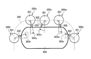
- FIG. 29 is an example of a state in which five faces 300t to 300x are arranged around the table 400 as viewed from directly above the table 400.
- a virtual line 340 that connects the centers of the faces 300t to 300x in order is defined, and the orientation of each face 300t to 300x is defined based on the normal at the position of the face with respect to the virtual line 340. In this way, the orientation of each face 300t to 300x is defined, and the group detection process according to the first embodiment or the second embodiment described above is performed.
- the face recognition unit 110 recognizes each face in the effective pixel area 202, face position information indicating the position of each recognized face in the effective pixel area 202, and each face in the effective pixel area 202. Face direction information indicating the orientation and face size information indicating the size of each face on the image are acquired. At this time, the face recognizing unit 110 acquires the direction of each face including a side face and a diagonally backward direction. For example, the face recognizing unit 110 acquires the face direction including the side face and the obliquely backward direction from the positional relationship between the face area of the face and each facial organ (eyes, nose, mouth, etc.). The face recognition unit 110 supplies the acquired face position information, face direction information, and face size information of each face to the group detection unit 111.
- the group detection unit 111 forms a provisional group based on the face position information and face size information of each face supplied from the face recognition unit 110.
- a temporary group is formed by the faces 300t to 300x shown in FIG.
- the group detection unit 111 connects the centers of the faces 300t to 300x belonging to the provisional group with a virtual line 340.
- the group detection unit 111 ignores the faces that are directly behind the camera 1 among the faces included in the provisional group.
- the group detection unit 111 uses any one of the faces 300t to 300x belonging to the temporary group, for example, the face 300t at the end as a starting point, and sets the faces 300u to 300x included in the temporary group in a predetermined direction, for example, A virtual line 340 is connected clockwise.
- the group detection unit 111 configures a virtual line 340 that smoothly connects the faces 300t to 300x using a Bezier curve or the like.
- the group detection unit 111 obtains the normal of each face 300t to 300x on the virtual line 340 for each face 300t to 300x connected by the virtual line 340. More specifically, the group detection unit 111 obtains a tangent to the virtual line 340 at the position of each face 300t to 300x on the virtual line 340, and obtains a normal to this tangent as a normal to each face 300t to 300x. . Then, the group detection unit 111 estimates the face orientation with respect to the normal line for each of the faces 300t to 300x.
- each face 300t to 300x is the normal line. It is estimated that the faces 300t, 300u and 300w are facing right according to the directions 303t, 303u and 303w with respect to. Further, it is estimated that the faces 300v and 300x are facing left in accordance with the directions 303v and 303x with respect to the normal.
- the group detection unit 111 follows any orientation of each face 300t to 300x detected according to the virtual line 340, as in the first embodiment or the second embodiment described above.
- a group can be formed based on the orientation of the face. For example, in the case of the group formation method of the first embodiment, assuming that group formation is performed from the leftmost face 300t in the virtual line 340, for example, the group detection unit 111 performs the face 300t, 300u, and 300v according to the flowchart of FIG. To form a first group, and the faces 300w and 300x form a second group.
- control signal output unit 112 can perform the pan operation and the zoom operation for each group formed in this way according to the modification of the third embodiment.
- the group detection unit 111 since the group detection unit 111 places the virtual line 340 in the three-dimensional space on the imaging surface that is a two-dimensional plane, the orientation of each face cannot be accurately determined. There is a case. Therefore, for example, the group detecting unit 111 may correct the orientation of each face based on the angle between the direction of the optical axis of the camera 1 and the plane on which the virtual line 340 is formed in the three-dimensional space.
Landscapes
- Engineering & Computer Science (AREA)
- Multimedia (AREA)
- Health & Medical Sciences (AREA)
- General Health & Medical Sciences (AREA)
- Oral & Maxillofacial Surgery (AREA)
- Human Computer Interaction (AREA)
- Physics & Mathematics (AREA)
- General Physics & Mathematics (AREA)
- Theoretical Computer Science (AREA)
- Signal Processing (AREA)
- Studio Devices (AREA)
Abstract
顔認識部(110)が、被写体を撮像した撮像画像に含まれる顔を認識する。そして、顔認識部は、認識された顔の向きと位置とをそれぞれ検出する。グループ検出部(111)は、撮像画像に含まれる顔のうち、顔認識部で検出された、互いに隣接する2つの顔の向きと位置とに基づき、撮像画像に含まれる顔によるグループを検出する。制御信号出力部(112)は、グループ検出部により検出されたグループの方向を示す制御信号を出力する。
Description
本発明は、撮像装置および撮像装置の制御方法に関する。
従来から、被写体を撮像した撮像画像に対して画像処理を施して、撮像画像から人間の顔を認識し、認識された人間の顔に対して自動的に合焦させるようにした撮像装置が知られている。また、撮像画像から認識した特定の顔を追尾するようにした撮像装置も、知られている。
一方、特許文献1には、複数の被写体が集まって構成されているグループ全体の映像や、グループ内の被写体のみの組み合わせの映像を撮像することが可能なカメラ制御システムが開示されている。この特許文献1において被写体を特定するための手法として、上述した顔認識技術を適用することが可能である。
ここで、撮像画像に被写体として含まれる複数の人物がグループを構成する場合、あるグループに含まれる各人物の間には、一定の関係が存在するものと考えられる。上述の特許文献1の技術においては、グループを被写体の大きさから求めた被写体間の距離に基づき形成している。
しかしながら、各被写体間の距離は、各被写体間に一定の関係が存在するか否かを判定する要因としては不十分であるという問題点があった。例えば、極めて近い距離にいる2の人物が互いに背を向けあっている場合、これら2の人物の間に一定の関係が存在すると画像から判定することは、困難であると考えられる。
本発明は、上記に鑑みてなされたものであって、撮像画像に含まれる人物によるグループを適切に形成可能な撮像装置および撮像装置の制御方法に関する。
上述した課題を解決し、目的を達成するために、本発明は、被写体を撮像して撮像画像を出力する撮像部と、撮像画像に含まれる顔を認識し、認識された顔の向きと位置とを検出する顔認識部と、撮像画像に含まれる顔のうち、互いに隣接する2の顔の向きと位置とに基づき、前記撮像画像に含まれる顔によるグループを検出するグループ検出部とを有することを特徴とする。
本発明によれば、撮像画像に含まれる人物によるグループを適切に形成可能となるという効果を奏する。
以下に図面を参照しながら、本発明に係る撮像装置および撮像装置の制御方法の好適な実施形態を説明する。係る実施形態に示す具体的な数値および外観構成などは、本発明の理解を容易とするための例示にすぎず、特に断る場合を除き、本発明を限定するものではない。なお、本発明に直接関係のない要素は詳細な説明および図示を省略している。
(第1の実施形態)
先ず、第1の実施形態について説明する。図1は、各実施形態に係る撮像装置であるカメラ1の外観例を示す。カメラ1は、カメラ本体10と基台20とを備える。カメラ本体10は、撮像レンズ11が設けられ、撮像レンズ11に入射された被写体からの光を電気信号に変換し、この電気信号に対して所定の信号処理を施してディジタルデータの動画像による撮像画像を得る。撮像画像は、所定の画像処理を施されて、例えばカメラ本体10から出力画像121として外部に出力される。
先ず、第1の実施形態について説明する。図1は、各実施形態に係る撮像装置であるカメラ1の外観例を示す。カメラ1は、カメラ本体10と基台20とを備える。カメラ本体10は、撮像レンズ11が設けられ、撮像レンズ11に入射された被写体からの光を電気信号に変換し、この電気信号に対して所定の信号処理を施してディジタルデータの動画像による撮像画像を得る。撮像画像は、所定の画像処理を施されて、例えばカメラ本体10から出力画像121として外部に出力される。
基台20は、水平回転部21と垂直回転部22とでカメラ本体10を水平および垂直方向にそれぞれ回転可能に保持する。水平回転部21および垂直回転部22は、例えばカメラ本体10からの制御に従い駆動され、カメラ本体10を水平および垂直方向に所定の角度範囲で回転させる。水平回転部21および垂直回転部22は、外部からの制御信号によって駆動することもできる。
図2は、各実施形態に係るカメラ1の一例の構成を示す。カメラ1は、光学部100と、撮像部101と、信号処理部102と、画像処理部103と、ズーム駆動部114と、パン・チルト駆動部116とを有する。
光学部100は、1以上のレンズを含む撮像レンズ11と、撮像レンズ11を駆動するレンズ駆動機構などを備える。被写体からの光は、撮像レンズ11に入射され、光学部100を介して撮像部101に出力される。撮像部101は、例えばCCD(Charge Coupled Device)やCMOS(Complementary Metal Oxide Semiconductor)イメージャなどの撮像素子を備え、光学部100から入射された光を光電変換により電気信号に変換して出力する。
撮像部101に入射された光に応じて撮像部101から出力された信号は、信号処理部102に供給される。信号処理部102は、撮像部101から供給された信号に対してノイズ除去処理やゲイン調整処理など所定の信号処理を施し、A/D変換によりディジタルデータに変換して撮像画像120として出力し、画像処理部103と、後述する顔認識部110とに供給する。信号処理部102は、撮像部101に含まれる構成としてもよい。画像処理部103は、信号処理部102から供給された撮像画像120に対してホワイトバランス補正処理やガンマ補正処理などの画像処理を施し、出力画像121としてカメラ1の外部に出力する。これに限らず、カメラ1にメモリなど記憶手段を設け、画像処理部103から出力された出力画像121をメモリに保持してもよい。
ズーム駆動部114は、後述する画角制御部113からの画角制御信号に従いレンズ駆動機構を駆動して撮像レンズ11の画角を制御し、ワイド端(広角端)およびテレ端(狭角端)との間でズーム動作を行う。パン・チルト駆動部116は、後述する方向制御部115からの方向制御信号に従い水平回転部21および垂直回転部22を駆動して、撮像レンズ11による撮像方向を変える。
カメラ1は、さらに、顔認識部110と、グループ検出部111と、制御信号出力部112と、画角制御部113と、方向制御部115とを有する。
顔認識部110は、信号処理部102から供給された撮像画像120に含まれる顔の認識を行う。顔認識部110は、撮像画像120に含まれる顔の認識を、既知の方法を用いて行うことができる。例えば、顔認識部110は、顔辞書とパターンマッチングを用いた部分空間法により、撮像画像120から顔領域および各顔器官を検出して、顔認識を行うことが考えられる。顔認識部110は、さらに、撮像画像120において認識された顔が向いている方向を検出する。顔認識部110は、例えば、認識された顔の顔領域および各顔器官(目、鼻、口など)の位置関係に基づき、当該顔が向いている方向を検出することができる。
顔認識部110は、例えば、顔認識結果に従い、認識された各顔の撮像画像120内での位置を示す顔位置情報と、各顔の向きを示す顔方向情報とを出力する。また、顔認識部110は、顔認識を行った撮像画像120を出力する。顔認識部110から出力された顔位置情報および顔方向情報と、撮像画像120とがグループ検出部111に供給される。
グループ検出部111は、顔認識部110から供給された顔位置情報および顔方向情報と、撮像画像120とに基づき、撮像画像120内で認識された各顔の組を含むグループを検出する。グループ検出部111は、検出したグループに含まれる顔の組の情報と撮像画像120とを制御信号出力部112に供給する。
制御信号出力部112は、グループ検出部111から供給された、グループに含まれる顔の組の情報と、撮像画像120とに基づき、カメラ1に対するグループの方向を求める。例えば、グループ検出部111は、グループに含まれる各顔に基づき、当該グループの顔による重心位置を求める。制御信号出力部112は、例えば、カメラ1の撮像レンズ11から、この求めた重心位置に向けた方向を、グループの方向として求め、方向を示す情報を出力する。
一例として、図3に例示されるように、カメラ1により撮像される撮像画像に対応する仮想的な撮像面51を考え、重心位置50がこの撮像面51上の点であるものとする。この仮想的な撮像面51は、例えば図4で後述する有効画素領域202に対応する。また、カメラ1と撮像面51との間の距離を距離Dとする。制御信号出力部112は、後述する画角制御部113から、撮像レンズ11による画角αを取得する。また、制御信号出力部112は、撮像画像から、撮像面51上における、撮像画像の中心から水平方向の端および重心位置までの各距離L1およびL2を取得する。
そして、制御信号出力部112は、画角αの1/2の角度である角度θと、各距離D、L1およびL2とから、下記の式(1)に従い、カメラ1の重心位置に向けた方向を示す方向角ψを求める。なお、距離Dは、式(1)の導出過程において相殺され式(1)には出現しない。
ψ=tan-1{(L2/L1)tanθ} …(1)
ψ=tan-1{(L2/L1)tanθ} …(1)
ここでは、制御信号出力部112がグループの重心位置をグループの方向を示す情報として求めるように説明したが、これは一例であって、この例に限定されない。すなわち、実際には、制御信号出力部112は、グループの水平方向の両端を構成する各顔の方向を示す情報をそれぞれ求め、グループの重心位置の方向を示す情報と共に、そのグループの方向を示す情報として出力する。
制御信号出力部112から出力された、グループの方向を示す情報は、画角制御部113と方向制御部115とに供給される。画角制御部113は、与えられた情報に従いズーム駆動部114を駆動して、撮像レンズ11による画角が所定の画角になるように制御する。例えば、画角制御部113は、制御信号出力部112から供給されたグループの方向を示す情報に従い、画角を算出する。そして、画角制御部113は、撮像レンズ11による画角が算出された画角になるように、ズーム駆動部114を駆動し、ズーム動作を行う。
方向制御部115は、与えられた情報に従いパン・チルト駆動部116を駆動して水平回転部21および垂直回転部22を回転させ、カメラ1による撮像方向が所定の方向を向くように制御する。例えば、方向制御部115は、制御信号出力部112から供給されたグループの方向を示す情報に従い、撮像方向の変化分を算出する。そして、方向制御部115は、カメラ1の撮像方向が算出された変化分だけ変化するように、パン・チルト駆動部116を駆動し、パン動作を行う。なお、ここでは、撮像方向を水平方向に変化させるパン動作と、撮像方向を垂直方向に変化させるチルト動作とを、纏めてパン動作と呼ぶ。
(用語などの定義)
次に、第1の実施形態に係るグループ検出について、より詳細に説明する。先ず、グループ検出の説明に先んじて、以下の説明に用いる各用語や図面表記などの定義を行う。図4は、撮像部101が有する撮像素子による撮像領域の例を示す。図4において、撮像素子200は、画素領域として、撮像素子200上の全ての画素で構成される総画素領域201と、総画素領域201内において画像信号として処理可能な領域である有効画素領域202とを含む。総画素領域201において、有効画素領域202外の領域は、オプチカルブラック領域などの画像信号を出力する領域として使用できない領域である。また、記録画素領域203は、有効画素領域202内で、出力画像121として処理される画像領域である。
次に、第1の実施形態に係るグループ検出について、より詳細に説明する。先ず、グループ検出の説明に先んじて、以下の説明に用いる各用語や図面表記などの定義を行う。図4は、撮像部101が有する撮像素子による撮像領域の例を示す。図4において、撮像素子200は、画素領域として、撮像素子200上の全ての画素で構成される総画素領域201と、総画素領域201内において画像信号として処理可能な領域である有効画素領域202とを含む。総画素領域201において、有効画素領域202外の領域は、オプチカルブラック領域などの画像信号を出力する領域として使用できない領域である。また、記録画素領域203は、有効画素領域202内で、出力画像121として処理される画像領域である。
例えば、撮像部101から、有効画素領域202の全域に対応する画像信号が出力される。信号処理部102は、撮像部101から供給されたこの画像信号に対して所定の信号処理を施して、有効画素領域202の全画素を含む画像を撮像画像120として出力する。画像処理部103は、信号処理部102から供給された撮像画像120から、記録画素領域203に対応する領域の画素を切り取り、出力画像121として出力する。
図5は、第1の実施形態に係る、顔の表示の例を示す。図5は、顔300を真上から見た状態を示す。図5において、顔300は、頭部301と鼻302とで簡略的に示されている。顔300は、鼻302が向いている方向を正面とし、正面を角度φ=0°と定義する。また、図において、角度は、反時計回りに0°から180°まで正方向に変化し、時計回りに0°から-180°まで負方向に変化する。
図6は、以下の説明における顔の方向の定義を示す。図6(a)は、顔をカメラ1側から見た場合の例を示す。また、図6(b)は、顔を真上から見た場合の方向の例を示す。図6(b)の場合、カメラ1は、図の下方に設置され、撮像レンズ11が上方を向けられているものとする。図6(a)および図6(b)に示すように、以下では、顔の向きをカメラ1から見た、頭部301に対する鼻302の向きによって定義するものとする。
例えば、図6(a)および図6(b)の顔300cに示すように、鼻302が頭部301の略中央にある場合に、顔300cが正面を向いているものとする。また、図6(a)および図6(b)の顔300aに示すように、鼻302が頭部301に対して左側に見える場合に、顔300aが左方向を向いているものとし、顔300bに示すように、鼻302が頭部301において左側にずれて見える場合に、顔300bが左斜め方向を向いているものとする。なお、以下では、左方向を向いている顔300aと、左斜め方向を向いている顔300bとを区別せず、顔300aおよび300bが共に左方向を向いているものとして扱う。
右方向を向いている顔300dおよび300eについても、同様である。すなわち、右斜め方向を向いている顔300dと、右方向を向いている顔300eとを区別せず、顔300dおよび300eが共に右方向を向いているものとして扱う。
また、2の顔が並んでいる場合、これら2の顔は、互いに向き合っている状態と向き合っていない状態との2の状態が定義される。図7を用いて、この2の状態について説明する。図7は、2の顔が並んでいる状態を、顔を上から見た例を示す。図7に例示されるように、顔300cおよび300c’が、互いに平行な方向350および351をそれぞれ向いている場合には、これら顔300cおよび300c’は、向き合っていないものとする。一方、顔300cおよび300c’が、方向350および351に対して内側の方向352および353をそれぞれ向いている場合には、これら顔300cおよび300c’は、向き合っているものとする。
実際には、互いに平行とされる方向に対してマージンを持たせ、2の顔の向きが平行から所定範囲内でぶれても、当該2の顔が平行であると見做すようにすると、好ましい。
図8および図9を用いて、カメラ1の撮像範囲と顔の位置との関係について説明する。信号処理部102は、撮像部101から供給される画像信号から、撮像レンズ11による画角の範囲において有効画素領域202の撮像画像120を得る。上述したように、この有効画素領域202による撮像画像120は、画像処理部103における画像処理により、有効画素領域202よりも小さい記録画素領域203が切り取られ、この記録画素領域203の画像が出力画像121とされる。
ここで、図8に例示されるように、有効画素領域202内に5の顔300a~300eが撮像され、そのうち3の顔300b~300dが記録画素領域203に含まれる場合について考える。信号処理部102から出力された撮像画像120は、画像処理部103と顔認識部110とに供給される。そのため、有効画素領域202に含まれ、且つ、記録画素領域203に含まれない顔300aおよび300eは、出力画像121には含まれない。その一方で、顔300aおよび300eは、記録画素領域203に含まれる顔300b~300dと同様に、顔認識部110における顔認識処理や、グループ検出部111におけるグループ検出処理の対象となる。
図9は、図8の状態に対応する、各顔300a~300eを真上から見た状態の例を示す。有効画素領域202の水平方向の領域202は、カメラ1の撮像レンズ11(光学部100)による画角に対応する。また、記録画素領域203の水平方向の領域203は、撮像レンズ11に対する角度が画角より小さい。
(グループ検出処理)
次に、第1の実施形態に係る、顔が属するグループの検出方法について説明する。第1の実施形態では、グループ検出部11は、互いに隣接する2の顔の向きと位置とに基づき、顔が属するグループを検出する。より具体的には、グループ検出部111は、顔認識部110で撮像画像120すなわち有効画素領域202から認識された各顔のうち、互いに向き合う方向を向いた2の顔を両端に含む顔の組を、グループとして検出する。
次に、第1の実施形態に係る、顔が属するグループの検出方法について説明する。第1の実施形態では、グループ検出部11は、互いに隣接する2の顔の向きと位置とに基づき、顔が属するグループを検出する。より具体的には、グループ検出部111は、顔認識部110で撮像画像120すなわち有効画素領域202から認識された各顔のうち、互いに向き合う方向を向いた2の顔を両端に含む顔の組を、グループとして検出する。
図10および図11は、第1の実施形態に係る、有効画素領域202に含まれる各顔300a~300eがグループを形成しない例について示す。図10は、有効画素領域202に含まれる各顔300a~300eが全て左を向いている例である。この場合、各顔300a~300eにおいて互いに向き合う方向を向いた顔の組が存在しないため、グループ検出部111は、グループが存在しないと判定する。
図11は、有効画素領域202に含まれる各顔300a~300eにおいて、互いに異なる方向を向いている顔が存在し、且つ、各顔300a~300eがグループを形成しない例である。図11において、顔300aおよび300bが左を向き、顔300c~300eが右を向いており、互いに向き合う方向を向いた顔の組が存在しないため、グループ検出部111は、グループが存在しないと判定する。
図12は、第1の実施形態に係る、有効画素領域202に含まれる各顔300a~300eがグループを形成する例について示す。図12において、グループ検出部111は、顔認識部110から供給された顔位置情報および顔方向情報に基づき、顔300bが右を向き、顔300bに隣接する顔300cが左を向いており、顔300bおよび300cが互いに向き合う方向を向いていると判定する。したがって、グループ検出部111は、顔300bおよび300cを両端とするグループ310aを検出する。さらに、グループ検出部111は、顔位置情報および顔方向情報に基づき、顔300dが右を向き、顔300dに隣接する顔300eが左を向いており、顔300dおよび300eが互いに向き合う方向を向いていると判定する。したがって、グループ検出部111は、顔300dおよび300eを両端とするグループ310bを検出する。
一方、グループ検出部111は、顔位置情報および顔方向情報に基づき、顔300aが左を向き、顔300aに隣接する顔300bが右を向いており、顔300aおよび300bが互いに向き合う方向を向いておらず、グループを形成していないと判定する。同様に、グループ検出部111は、顔300cが左を向き、顔300cに隣接する顔300dが右を向いており、顔300cおよび303dが互いに向き合う方向を向いておらず、グループを形成してないと判定する。
なお、例えば図9における顔300cのように、カメラ1に対して正面を向いている顔は、グループの端を構成しないものとする。また、顔がカメラ1に対して上方、下方または後ろなどを向き、顔検出できない場合も有り得る。このような場合は、そもそも顔が検出されないため、これらの状態の顔はグループの端を構成しない。
図13は、第1の実施形態に係るグループ検出部111によるグループ検出処理の例を示すフローチャートである。図13のフローチャートによる処理は、所定の間隔、例えば撮像画像120のフレーム周期の間隔で繰り返して実行される。第1の実施形態では、グループ検出部111は、有効画素領域202における水平方向の一方の端から他方の端に向けて、順次各顔の方向を判定し、グループを検出する。以下の例では、グループ検出部111は、有効画素領域202の左端から右端に向けて、各顔の向きを判定するものとする。
図13において、ステップS100で、グループ検出部111は、現在判定対象としている顔の右に次の顔が存在するか否かを判定する。有効画素領域202に対する最初の処理である場合には、グループ検出部111は、当該有効画素領域202内に顔が存在するか否かを判定することになる。グループ検出部111は、次の顔が存在しないと判定した場合、有効画素領域202内にグループが存在しないとして、図13のフローチャートにおける一連の処理を終了する。
グループ検出部111は、ステップS100で次の顔が存在すると判定した場合、当該次の顔を対象の顔として、処理をステップS101に移行させる。ステップS101で、グループ検出部111は、対象の顔の向きを判定する。グループ検出部111は、対象の顔の向きが左または正面向きであると判定した場合、処理をステップS100に戻す。
グループ検出部111は、ステップS101で、対象の顔の向きが右向きであると判定した場合、処理をステップS102に移行させ、当該対象の顔をグループ候補に登録する。グループ検出部111は、次のステップS103で、対象の顔の右に次の顔が存在するか否かを判定する。グループ検出部111は、次の顔が存在しないと判定した場合、図13のフローチャートによる一連の処理を終了する。この場合、ステップS102で顔が登録されたグループ候補は、破棄される。
グループ検出部111は、ステップS103で次の顔が存在すると判定した場合、当該次の顔を新たな対象の顔として、処理をステップS104に移行させる。ステップS104で、グループ検出部111は、対象の顔の向きを判定する。グループ検出部111は、対象の顔の向きが右または正面向きであると判定した場合、処理をステップS102に戻し、当該対象の顔をグループ候補に追加登録する。
グループ検出部111は、ステップS104で、対象の顔の向きが左向きであると判定した場合、処理をステップS105に移行させ、当該対象の顔をグループ候補に追加登録する。グループ検出部111は、次のステップS106で、対象の顔の右に次の顔が存在するか否かを判定する。グループ検出部111は、次の顔が存在しないと判定した場合、処理をステップS110に移行させ、グループ候補に登録された顔でグループを形成する。そして、図13のフローチャートによる一連の処理を終了する。
グループ検出部111は、ステップS106で次の顔が存在すると判定した場合、当該次の顔を新たな対象の顔として、処理をステップS107に移行させる。ステップS107で、グループ検出部111は、対象の顔の向きを判定する。グループ検出部111は、対象の顔の向きが左または正面向きであると判定した場合、処理をステップS105に戻し、当該対象の顔をグループ候補に追加登録する。
グループ検出部111は、ステップS107で、対象の顔の向きが右向きであると判定した場合、処理をステップS108に移行させ、グループ候補に登録された顔でグループを形成する。このとき、グループ検出部111は、形成したグループに、当該グループを識別する識別情報を付与する。ここでは、識別情報を、値が「1」からインクリメントされるグループ番号であるものとする。
グループ検出部111は、次のステップS109で、グループ番号を例えば1だけインクリメントして、次のグループの検出処理を準備する。そして、グループ検出部111は、処理をステップS100に戻し、ステップS106で存在すると判定した顔の右に次の顔が存在するか否かを判定する。
グループ検出部111は、この図13のフローチャートによる処理を、所定の時間間隔で繰り返して実行することにより、顔の向きの変化に対応してグループを検出することができる。例えば、上述した図12の状態から顔300eが右向きに変化した場合、グループ検出部111は、顔300eが右向きの状態で、各顔300a~300eによるグループを検出する。この場合には、グループ310bを構成していた顔300dおよび300eが共に右向きとなってしまうため、グループ310bが消滅する。したがって、グループ検出部111は、図13のフローチャートに従い、顔300bおよび300cによるグループ310aのみを検出することになる。
また、図12の状態から、顔300dの向きが左向きに変化した場合、グループ検出部111は、顔300dが左向きの状態で、各顔300a~300eによるグループを検出する。すなわち、図14に例示されるように、顔300dが左を向くことで、顔300bおよび300dが互いに向き合う方向を向くため、顔300bおよび300cにより形成されるグループ310aが拡張され、これら顔300bおよび300dを両端とする顔の組を含むグループ310a’が形成される。したがって、グループ検出部111は、図13のフローチャートに従い、顔300b、300cおよび300dによるグループ310a’を検出することになる。
(グループに注目した撮像動作)
次に、第1の実施形態に係る、グループに注目した撮像動作について説明する。第1の実施形態では、ズーム動作やパン動作などにより、グループ検出部111が検出したグループに注目した撮像を行う。
次に、第1の実施形態に係る、グループに注目した撮像動作について説明する。第1の実施形態では、ズーム動作やパン動作などにより、グループ検出部111が検出したグループに注目した撮像を行う。
一例として、図15に示されるように、顔300a~300eのうち顔300bおよび300cがグループ310cを形成しているものとする。また、図15において、グループ310c(顔300bおよび300c)と、顔300dとが記録画素領域203に含まれ、顔300a~300eが有効画素領域202に含まれているものとする。
この状態において、図16に例示されるように、カメラ1は、カメラ1をグループ310cの方向にパンすると共に、レンズ11をテレ端側にズームして、記録画素領域203が顔300bおよび300cを含み顔300dを含まないように撮像を行う。これにより、カメラ1は、グループ310cすなわち顔300bおよび300cが注目された出力画像121を得ることができる。
このとき、カメラ1は、顔300bおよび顔300cが最大限に画角内に収まるようにズーム動作およびパン動作を行なってもよいし、それぞれの顔の縦横の幅を考慮して、顔の幅を記録画素領域203に対して所定の割合になるように画角および撮像方向を設定してもよい。これによって、カメラ1は、顔のズーム映像やバストアップ映像など様々な構図でグループを撮影できる。
図17は、第1の実施形態に係る、グループに注目した撮像動作の例を示すフローチャートである。図17において、ステップS120で、グループ検出部111は、上述した図13のフローチャートに従い、撮像画像120すなわち有効画素領域202に含まれる全グループの検出を行う。次のステップS121で、制御信号出力部112は、ステップS120で検出された全グループによる重心が出力画像121すなわち記録画素領域203の中心に位置するようにパンさせるための制御信号を出力する。方向制御部115は、この制御信号に従いパン・チルト駆動部116を制御して、カメラ1の撮像方向を変更させる。
ここで、重心は、例えばグループの重心の場合、グループに含まれる各顔のグループ内での相対位置を平均した値である。また、全グループによる重心は、各グループの重心を平均した値である。
次のステップS122で、制御信号出力部112は、カメラ1の撮像モードが一括モードおよび個別モードの何れであるかを判定する。一括モードは、撮像画像120に含まれる全グループを一括して撮像するための動作モードである。また、個別モードは、撮像画像120に含まれる全グループを、グループ毎に撮像するための動作モードである。なお、カメラ1は、例えば、図示されない操作部に対するユーザ操作に応じて撮像モードを設定可能とされている。
制御信号出力部112は、ステップS122で、カメラ1の動作モードが一括モードであると判定した場合、処理をステップS123に移行させる。ステップS123で、制御信号出力部112は、全グループにおける最も左にあるグループに含まれる左端の顔の位置と、最も右にあるグループに含まれる右端の顔によって構成される全グループにおける両端位置と、撮像レンズ11による画角に基づき、ズーム動作により全グループが画像内すなわち記録画素領域203内に収まるか否かを判定する。
例えば、制御信号出力部112は、撮像レンズ11を広角端にズーム動作した場合の画角βと、全グループにおける両端位置の仮想的な撮像面51における位置とを取得して、上述した式(1)に基づきステップS123による判定を行うことが考えられる。この場合、制御信号出力部112は、撮像レンズ11の光軸の撮像面51における位置を基準として、当該各顔のうち撮像レンズ11の光軸から遠い方の顔の光軸との距離を距離L2として、上述の式(1)から角度ψを求める。そして、制御信号出力部112は、角度ψと角度(β/2)とを比較した結果に基づき、全グループが画像内すなわち記録画素領域203内に収まるか否かを判定する。
制御信号出力部112は、ステップS123において、ズーム動作により撮像レンズ11の画角を所定画角、例えば広角端に広げた場合に全グループが記録画素領域203内に収まると判定した場合、処理をステップS124に移行させる。ステップS124で、制御信号出力部112は、全グループが画像内すなわち記録画素領域203内に収まるようなズーム動作を行うための制御信号を出力し、画角制御部113に供給する。そして、図17のフローチャートによる一連の処理が終了する。
この場合、制御信号出力部112は、撮像レンズ11を所定画角に広げるように駆動するための制御信号を生成することが考えられる。これに限らず、制御信号出力部112は、撮像レンズ11の画角を上述したステップS123で式(1)を用いて求めた角度ψに基づき制御するための制御信号を生成してもよい。
制御信号出力部112は、ステップS123で、ズーム動作により撮像レンズ11の画角を所定画角に広げた場合に全グループが記録画素領域203内に収まらないと判定した場合、処理をステップS125に移行させる。ステップS125で、制御信号出力部112は、撮像レンズ11を所定画角、例えば広角端にズーム動作させ、且つ、カメラ1をグループ毎にパン動作させるための制御信号を出力し、画角制御部113および方向制御部115に供給する。
ステップS125の動作について、図18および図19を用いて説明する。図18は、有効画素領域202内に、グループ310dおよびグループ310eの2のグループが、比較的近い距離に形成された例を示す。この図18の例では、カメラ1は、撮像レンズ11を例えば広角端にズーム動作させ、グループ310dおよび310eの重心に向けてパン動作させることで、記録画素領域203にグループ310dおよび310eを含ませることができる。
この場合、制御信号出力部112は、例えば広角端にズーム動作をさせるための制御信号を生成して画角制御部113に供給する。それと共に、制御信号出力部112は、グループ310dおよび310eの重心に向けてパン動作させるための制御信号を生成して方向制御部115に供給する。
一方、図19は、有効画素領域202内に、グループ310fおよびグループ310gの2のグループが、比較的遠い距離に形成された例を示す。この図19の例では、カメラ1は、撮像レンズ11を例えば広角端にズーム動作させ、且つ、グループ310fおよび310gの重心に向けてパン動作させても、グループ310fおよび310gのうち一部が記録画素領域203からはみ出てしまう。この場合、カメラ1は、撮像レンズ11を例えば広角端にズーム動作させ、先ず、例えばグループ310fの重心に向けてパン動作させる。次に、カメラ1は、撮像レンズ11を例えば広角端にズーム動作させたまま、グループ310gの重心に向けてパン動作させる。これにより、記録画素領域203に、グループ310fおよび310gを順次、含ませることができる。
この場合、制御信号出力部112は、先ず、例えば広角端にズーム動作をさせるための制御信号を生成して画角制御部113に供給すると共に、グループ310fの重心に向けてパン動作させるための制御信号を生成して方向制御部115に供給する。そのパン動作の所定時間後に、制御信号出力部112は、グループ310gの重心に向けてパン動作させるための制御信号を生成して方向制御部115に供給する。その後、図17のフローチャートによる一連の処理が終了される。
上述のステップS122で、制御信号出力部112は、カメラ1の動作モードが個別モードであると判定した場合、処理をステップS126に移行させる。ステップS126で、制御信号出力部112は、カメラ1をグループ毎にパン動作させ、且つ、撮像レンズ11をグループ毎にテレ端側にズーム動作させるための制御信号を生成し、方向制御部115および画角制御部113に供給する。
図20は、このステップS126による、グループ毎にパン動作およびズーム動作を行う場合の例を示す。図20において、顔300b’および300c’によりグループ310fが形成され、グループ310fの右側に顔300d’および300e’によりグループ310gが形成されている。
左側のグループから順にパン動作を行う場合、制御信号出力部112は、先ず、グループ310fの重心の方向を求めると共に、グループ310fに含まれる顔300b’および300c’の仮想的な撮像面51上の各位置(有効画素領域202における位置)を求め、求めた各位置が記録画素領域203の例えば両端(実際には、各顔300b’および300c’の輪郭を考慮した各位置)に位置するような画角γ1を算出する。この場合、画角γ1は、例えば現在の画角αと顔300b’および300c’の撮像面51上の位置と、テレ端へのズーム動作後の顔300b’および300c’の撮像面51上の位置とに基づき、上述した式(1)を用いて算出することができる。
制御信号出力部112は、グループ310fの重心の方向にパン動作させるための制御信号を生成して方向制御部115に供給する。それと共に、撮像レンズ11の画角を算出した画角γ1に変更させるための制御信号を生成して画角制御部113に供給する。
制御信号出力部112は、方向制御部115および画角制御部113によりそれぞれ制御信号に従いパン動作およびズーム動作がなされた所定時間後に、上述と同様にして、グループ310gの重心の方向を求め、顔300d’および300e’に対してズーム動作をさせるための画角γ2を算出する。そして、制御信号出力部112は、グループ310gの重心の方向にパン動作させるための制御信号を生成して方向制御部115に供給し、撮像レンズ11の画角を算出した画角γ2に変更させるための制御信号を生成して画角制御部113に供給する。
ステップS126において、有効画素領域202に含まれる全てのグループに対してパン動作およびズーム動作が行われたら、図17のフローチャートによる一連の処理が終了される。これに限らず、カメラ1は、有効画素領域202に含まれる各グループに対するパン動作およびズーム動作を繰り返してもよい。
ここで、有効画素領域202に含まれる各顔のうち例えば1つの顔が、極めて短時間、方向を変えた場合について考える。上述した図13のフローチャートによる処理を、フレーム周期など所定周期で繰り返して実行する場合、顔の短時間の方向変化が検出されてしまい、方向変化の検出毎にグループ構成が変化するおそれがある。方向変化の検出毎にグループ構成が変化した場合、カメラ1は、方向変化の検出毎に図17のフローチャートに従ったパン動作およびズーム動作を実行し、出力画像121による表示などが落ち着かないものとなってしまう可能性がある。
この現象は、例えば、図17のステップS124、ステップS125およびステップS126の各動作の実行タイミングに対してローパスフィルタ処理を施すことで抑制可能である。すなわち、ローパスフィルタ処理により、短時間の顔の向きの変化に対する各動作の反応が抑制され、落ち着いた表示を実現できる。
以上説明したように、第1の実施形態によれば、撮像画像120に含まれる各顔を適切にグルーピングできる。また、各顔のグルーピング結果に応じてパン動作およびズーム動作を実行できるため、複数の顔が含まれる撮像画像120において、互いに関連する顔に注目することができる。
(第2の実施形態)
次に、第2の実施形態について説明する。上述の第1の実施形態では、有効画素領域202の左右の何れかの端から順に顔の向きを判定してグループを形成していた。これに対して、第2の実施形態では、有効画素領域202に含まれる顔のうち、ターゲットとして指定された顔を含むグループを形成する。
次に、第2の実施形態について説明する。上述の第1の実施形態では、有効画素領域202の左右の何れかの端から順に顔の向きを判定してグループを形成していた。これに対して、第2の実施形態では、有効画素領域202に含まれる顔のうち、ターゲットとして指定された顔を含むグループを形成する。
図21を用いて、第2の実施形態によるグループ形成について説明する。図21において、有効画素領域202内に含まれる顔300a、300b、320、300dおよび300eのうち、顔320を、グループ形成のターゲットとして指定する。以下、顔320をターゲット320と呼ぶ。
第2の実施形態では、有効画素領域202に含まれる顔のうち、ターゲット320と、ターゲット320の方を向いている顔とを含むグループ321(ターゲット所属グループ321と呼ぶ)を形成する。このとき、ターゲット320が左、左斜め、正面、右斜めおよび右の何れの方向を向いているかは、問わない。
図21の例では、ターゲット320は、有効画素領域202に含まれる各顔の中央に位置する。これに対して、ターゲット320の左側に位置する顔300aは、左向きであってターゲット320の方を向いておらず、ターゲット所属グループ321に含まれない。一方、ターゲット320の左側に位置する顔300bは、右向きであって、ターゲット320の方を向いており、ターゲット所属グループ321に含まれる。また、ターゲット320の右側に位置する顔300dおよび300eは、それぞれ左向きであって、ターゲット320の方を向いており、ターゲット所属グループ321に含まれる。
なお、ターゲット所属グループ321に対するズーム動作やパン動作は、上述した第1の実施形態と同様であるので、ここでの説明を省略する。
図22~図25のフローチャートを用いて、第2の実施形態に係るグループ検出部111によるグループ検出処理の例について説明する。なお、図22~図25において、符号「A」、「B」および「C」は、対応する符号に処理が移行されることを示す。また、以下において、ターゲット320は、必ずグループに属するものとする。換言すれば、1のターゲット320のみが所属するグループも形成可能である。
以下に説明する図22~図25のフローチャートによる処理に先んじて、グループ検出部111に対して、有効画素領域202内の顔のうち何れかがターゲット320として指定される。例えば、カメラ1に設けられた図示されない操作部に対するユーザ操作により、ターゲット320を指定することが考えられる。図22~図25のフローチャートによる処理は、所定の間隔、例えば撮像画像120のフレーム周期の間隔で繰り返して実行される。
図22において、ステップS200で、グループ検出部111は、先ずターゲット320の顔をグループの候補に登録する。次のステップS201で、グループ検出部111は、ターゲット320の顔を注目の顔として設定する。そして、次のステップS202で、グループ検出部111は、ターゲット320の顔の向きが左向き、正面向きおよび右向きの何れであるかを判定する。グループ検出部111は、ステップS202でターゲット320の顔の向きが正面向きであると判定した場合、符号「B」に従い、処理を図23のフローチャートによる処理に移行させる。
処理が図23のフローチャートに移行されると、ステップS210で、グループ検出部111は、注目の顔の左に顔が存在するか否かを判定する。若し、存在すると判定した場合、グループ検出部111は、処理をステップS211に移行させ、注目の顔の左に存在する顔の向きを判定する。グループ検出部111は、注目の顔の左に存在する顔が右および正面の何れかを向いていると判定した場合、処理をステップS212に移行させ、注目の顔の左に存在する顔をグループ候補に登録する。そして、次のステップS213で、グループ検出部111は、この注目の顔の左に存在する顔を新たな注目の顔として、注目の顔を更新する。そして、処理をステップS210に戻す。
一方、グループ検出部111は、上述のステップS210で、注目の顔の左に顔が存在しないと判定した場合、または、上述のステップS211で、注目の顔の左に存在する顔が左を向いていると判定した場合、処理をステップS214に移行させる。ステップS214で、グループ検出部111は、ターゲット320の顔の左に顔が存在するか否かを判定する。若し、ターゲット320の顔の左に顔が存在すると判定した場合、グループ検出部111は、処理をステップS215に移行させる。ステップS215で、グループ検出部111は、グループ候補に右向きの顔が登録されているか否かを判定し、登録されていると判定した場合、処理をステップS216に移行させる。
一方、グループ検出部111は、ステップS214でターゲット320の顔の左に顔が存在しないと判定するか、または、ステップS215でグループ候補に右向きの顔が登録されていないと判定した場合、処理をステップS226に移行させる。
ステップS226で、グループ検出部111は、グループ候補に登録されている顔のうち、ターゲット320の顔以外の顔を削除する。これにより、グループ候補には、ターゲット320の顔のみが登録されている状態になる。グループ検出部111は、ステップS226の処理が終了すると、処理を後述するステップS225に移行させる。
ステップS216で、グループ検出部111は、グループ候補に登録されている顔のうち最も左に位置する右向きの顔よりも左側の登録を削除する。これにより、グループ候補に登録されている顔のうち、正面向きの顔が左端側から削除され、グループ候補の左端には、右向きの顔が登録されることになる。
次に、グループ検出部111は、処理をステップS217に移行させ、再びターゲット320の顔を注目の顔に設定する。そして、次のステップS218で、グループ検出部111は、注目の顔の右に顔が存在するか否かを判定する。若し、存在すると判定した場合、グループ検出部111は、処理をステップS219に移行させ、注目の顔の右に存在する顔の向きを判定する。グループ検出部111は、注目の顔の右に存在する顔が左および正面の何れかを向いていると判定した場合、処理をステップS220に移行させ、注目の顔の右に存在する顔をグループ候補に登録する。そして、次のステップS221で、グループ検出部111は、この注目の顔の右に存在する顔を新たな注目の顔として、注目の顔を更新する。そして、処理をステップS218に戻す。
一方、グループ検出部111は、上述のステップS218で、注目の顔の右に顔が存在しないと判定した場合、または、上述のステップS219で、注目の顔の右に存在する顔が右を向いていると判定した場合、処理をステップS222に移行させる。ステップS222で、グループ検出部111は、ターゲット320の顔の右に顔が存在するか否かを判定する。若し、ターゲット320の顔の右に顔が存在すると判定した場合、グループ検出部111は、処理をステップS223に移行させる。ステップS223で、グループ検出部111は、グループ候補に左向きの顔が登録されているか否かを判定し、登録されていると判定した場合、処理をステップS224に移行させる。
一方、グループ検出部111は、ステップS222でターゲット320の顔の右に顔が存在しないと判定するか、または、ステップS223でグループ候補に、ターゲットより右側に左向きの顔が登録されていないと判定した場合、処理をステップS226に移行させ、グループ候補に登録された顔のうちターゲット320の顔以外の顔を削除する。
ステップS224で、グループ検出部111は、グループ候補に登録されている顔のうち、最も右に位置する左向きの顔よりも右側にある顔の登録を削除する。これにより、グループ候補に登録されている顔のうち、正面向きの顔が右端側から削除され、グループ候補の右端には、左向きの顔が登録されることになる。
次のステップS225で、グループ検出部111は、グループ候補に登録されている顔でグループを構成する。そして、図23による、ターゲット320が正面を向いている場合の一連の処理が終了される。
上述した図22のフローチャートのステップS202で、グループ検出部111は、ターゲット320の顔の向きが左向きであると判定した場合、符号「A」に従い、処理を図24のフローチャートによる処理に移行させる。
図24のフローチャートによる処理は、上述した図23のフローチャートによる処理からステップS226の処理を取り去った処理となる。すなわち、グループ検出部111は、ステップS240で、注目の顔の左に顔が存在するか否かを判定し、存在すると判定した場合、次のステップS241で注目の顔の左に存在する顔の向きを判定する。グループ検出部111は、注目の顔の左に存在する顔が右および正面の何れかを向いていると判定した場合、処理をステップS242に移行させ、注目の顔の左に存在する顔をグループ候補に登録する。そして、次のステップS243で、グループ検出部111は、この注目の顔の左に存在する顔を新たな注目の顔として注目の顔を更新し、処理をステップS240に戻す。
一方、グループ検出部111は、上述のステップS240で、注目の顔の左に顔が存在しないと判定した場合、または、上述のステップS241で、注目の顔の左に存在する顔が左を向いていると判定した場合、処理をステップS244に移行させ、ターゲット320の顔の左に顔が存在するか否かを判定する。存在すると判定した場合、グループ検出部111は、処理をステップS245に移行させ、グループ候補に右向きの顔が登録されているか否かを判定し、登録されていると判定した場合、処理をステップS246に移行させる。ステップS246で、グループ検出部111は、グループ候補に登録されている顔のうち、最も左に位置する右向きの顔よりも左側にある顔の登録を削除する。
一方、グループ検出部111は、ステップS244でターゲット320の顔の左に顔が存在しないと判定するか、または、ステップS245でグループ候補に右向きの顔が登録されていないと判定した場合、処理を後述するステップS255に移行させる。
ステップS246の処理の後、グループ検出部111は、処理をステップS247に移行させ、再びターゲット320の顔を注目の顔に設定する。そして、次のステップS248で、グループ検出部111は、注目の顔の右に顔が存在するか否かを判定し、存在すると判定した場合、次のステップS249に移行で、注目の顔の右に存在する顔の向きを判定する。グループ検出部111は、注目の顔の右に存在する顔が左および正面の何れかを向いていると判定した場合、処理をステップS250に移行させ、注目の顔の右に存在する顔をグループ候補に登録する。そして、次のステップS251で、グループ検出部111は、この注目の顔の右に存在する顔を新たな注目の顔として注目の顔を更新し、処理をステップS248に戻す。
一方、グループ検出部111は、上述のステップS248で、注目の顔の右に顔が存在しないと判定した場合、または、上述のステップS249で、注目の顔の右に存在する顔が右を向いていると判定した場合、処理をステップS252に移行させる。ステップS252で、グループ検出部111は、ターゲット320の顔の右に顔が存在するか否かを判定し、存在すると判定した場合、処理をステップS253に移行させる。ステップS253で、グループ検出部111は、グループ候補に左向きの顔が登録されているか否かを判定し、登録されていると判定した場合、処理をステップS254に移行させる。ステップS254で、グループ検出部111は、グループ候補に登録されている顔のうち、最も右に位置する左向きの顔よりも右側にある顔の登録を削除する。
次のステップS255で、グループ検出部111は、グループ候補に登録されている顔でグループを構成する。そして、図24による、ターゲット320が左を向いている場合の一連の処理が終了される。
上述した図22のフローチャートのステップS202で、グループ検出部111は、ターゲット320の顔の向きが右向きであると判定した場合、符号「C」に従い、処理を図25のフローチャートによる処理に移行させる。
図25のフローチャートによる処理は、上述した図24のフローチャートによる処理において左右の記述を入れ替えたものになる。すなわち、グループ検出部111は、ステップS260で、注目の顔の右に顔が存在するか否かを判定し、存在すると判定した場合、次のステップS261で注目の顔の右に存在する顔の向きを判定する。グループ検出部111は、注目の顔の右に存在する顔が左および正面の何れかを向いていると判定した場合、処理をステップS262に移行させ、注目の顔の右に存在する顔をグループ候補に登録する。そして、次のステップS263で、グループ検出部111は、この注目の顔の右に存在する顔を新たな注目の顔として注目の顔を更新し、処理をステップS260に戻す。
一方、グループ検出部111は、上述のステップS260で、注目の顔の右に顔が存在しないと判定した場合、または、上述のステップS261で、注目の顔の右に存在する顔が右を向いていると判定した場合、処理をステップS264に移行させ、ターゲット320の顔の右に顔が存在するか否かを判定する。存在すると判定した場合、グループ検出部111は、処理をステップS265に移行させ、グループ候補に左向きの顔が登録されているか否かを判定し、登録されていると判定した場合、処理をステップS266に移行させる。ステップS266で、グループ検出部111は、グループ候補に登録されている顔のうち、最も右に位置する左向きの顔よりも右側にある顔の登録を削除する。
一方、グループ検出部111は、ステップS264でターゲット320の顔の右に顔が存在しないと判定するか、または、ステップS265でグループ候補に左向きの顔が登録されていないと判定した場合、処理を後述するステップS275に移行させる。
ステップS266の処理の後、グループ検出部111は、処理をステップS267に移行させ、再びターゲット320の顔を注目の顔に設定する。そして、次のステップS268で、グループ検出部111は、注目の顔の左に顔が存在するか否かを判定し、存在すると判定した場合、次のステップS269に移行で、注目の顔の左に存在する顔の向きを判定する。グループ検出部111は、注目の顔の左に存在する顔が右および正面の何れかを向いていると判定した場合、処理をステップS270に移行させ、注目の顔の左に存在する顔をグループ候補に登録する。そして、次のステップS271で、グループ検出部111は、この注目の顔の左に存在する顔を新たな注目の顔として注目の顔を更新し、処理をステップS268に戻す。
一方、グループ検出部111は、上述のステップS268で、注目の顔の左に顔が存在しないと判定した場合、または、上述のステップS269で、注目の顔の左に存在する顔が左を向いていると判定した場合、処理をステップS272に移行させる。ステップS272で、グループ検出部111は、ターゲット320の顔の左に顔が存在するか否かを判定し、存在すると判定した場合、処理をステップS273に移行させる。ステップS273で、グループ検出部111は、グループ候補に右向きの顔が登録されているか否かを判定し、登録されていると判定した場合、処理をステップS274に移行させる。ステップS274で、グループ検出部111は、グループ候補に登録されている顔のうち、最も左に位置する右向きの顔よりも左側にある顔の登録を削除する。
次のステップS275で、グループ検出部111は、グループ候補に登録されている顔でグループを構成する。そして、図24による、ターゲット320が右を向いている場合の一連の処理が終了される。
図26は、第2の実施形態に係る、ターゲットの顔を含むグループに注目した撮像動作の例を示すフローチャートである。図26において、ステップS150で、グループ検出部111に対して、有効画素領域202内の顔のうち何れかがターゲットとして指定される。次のステップS151で、グループ検出部111は、上述の図22のフローチャートよる処理に従って、ターゲットを含むターゲット所属グループを形成する。
次のステップS152で、グループ検出部111は、上述の図13のフローチャートによる処理に従い、有効画素領域202に含まれる顔により形成される全てのグループを検出する。このとき、グループ検出部111は、有効画素領域202に含まれる各顔のうち、ターゲット所属グループに含まれる顔を除外して、グループを形成する。
次のステップS153で、制御信号出力部112は、ステップS151で検出されたターゲット所属グループの重心が出力画像121すなわち記録画素領域203の中心に位置するようにパンさせる制御信号を出力する。方向制御部115は、この制御信号に従い、パン・チルト駆動部116を制御して、カメラ1の撮像方向を変更させる。
次のステップS154で、制御信号出力部112は、カメラ1の撮像モードが一括および個別モードの何れであるかを判定する。制御信号出力部112は、ステップS154で、カメラ1の動作モードが一括モードであると判定した場合、処理をステップS155に移行させる。ステップS155で、制御信号出力部112は、ズーム動作によりターゲット所属グループが画像内すなわち記録画素領域203内に収まるか否かを判定する。ここでの判定は、上述した図17のフローチャートにおけるステップS123の処理と同様の手順にて実行可能である。
制御信号出力部112は、ステップS155において、ズーム動作によりターゲット所属グループが記録画素領域203内に収まると判定した場合、処理をステップS156に移行させる。ステップS156で、制御信号出力部112は、ターゲット所属グループが画像内すなわち記録画素領域203内に収まるようなズーム動作を行うための制御信号を出力し、画角制御部113に供給する。そして、図23のフローチャートによる一連の処理が終了する。
制御信号出力部112は、ステップS155で、ズーム動作によりターゲット所属グループが記録画素領域203内に収まらないと判定した場合、処理をステップS157に移行させる。ステップS157で、制御信号出力部112は、撮像レンズ11を例えば広角端にズーム動作させ、且つ、ターゲット所属グループ内を撮像するようにカメラ1をパン動作させるための制御信号を出力し、画角制御部113および方向制御部115に供給する。そして、図26のフローチャートによる一連の処理が終了する。
なお、図22~図25のフローチャートで説明したように、ターゲット所属グループ内にターゲット320の顔のみが存在する場合が有り得る。このような場合、カメラ1は、ステップS157において、ターゲット所属グループ内のパンを行う代わりに、ターゲット320の顔が適切な大きさで撮像されるようにズーム動作を行うとよい。
制御信号出力部112は、ステップS154において、カメラ1の動作モードが個別モードであると判定した場合、処理をステップS158に移行させる。ステップS158で、制御信号出力部112は、ズーム動作によりターゲット所属グループが画像内すなわち記録画素領域203内に収まるか否かを判定する。
制御信号出力部112は、ステップS158において、ズーム動作によりターゲット所属グループが記録画素領域203内に収まると判定した場合、処理をステップS159に移行させる。ステップS159で、制御信号出力部112は、ターゲット所属グループが画像内すなわち記録画素領域203内に収まるように撮像レンズ11をズーム動作させ、且つ、カメラ1を、ターゲット所属グループを含む全てのグループ毎にパン動作させるための制御信号を出力し、画角制御部113および方向制御部115に供給する。そして、図26のフローチャートによる一連の処理が終了する。
このとき、ステップS159において、カメラ1は、ターゲット所属グループの撮像を他のグループの撮像動作と異なる動作で行うことで、撮像画像120においてターゲット所属グループをより目立たせることができる。このような撮像動作の例としては、ターゲット所属グループを撮像する場合のみ、他のグループと比べて長い時間撮像する、他のグループよりも撮像レンズ11をテレ端側にズーム動作させてアップで撮像する、他のグループよりもゆっくりパン動作して撮像する、などが考えられる。
制御信号出力部112は、ステップS158において、ズーム動作によりターゲット所属グループが記録画素領域203内に収まらないと判定した場合、処理をステップS160に移行させる。ステップS160で、制御信号出力部112は、撮像レンズ11を例えば広角端にズーム動作させ、且つ、カメラ1をターゲット所属グループ内でパン動作させるための制御信号を出力し、画角制御部113および方向制御部115に供給する。さらに、制御信号出力部112は、カメラ1のターゲット所属グループ内のパン動作が終了すると、各グループ毎にパン動作させるための制御信号を出力し、方向制御部115に供給する。そして、図26のフローチャートによる一連の処理が終了する。
なお、上述したように、ターゲット所属グループ内にターゲット320の顔のみが存在する場合が有り得る。このような場合、カメラ1は、ステップS160において、ターゲット所属グループ内のパンを行う代わりに、ターゲット320の顔が適切な大きさで撮像されるようにズーム動作を行うとよい。
ステップS160において、カメラ1は、ターゲット所属グループ内をパン動作させる際に、ターゲットの顔の撮像を他の顔の撮像動作と異なる動作で行うことで、ターゲットの顔をより目立たせることができる。このような撮像動作の例としては、ターゲットの顔を撮像する場合のみ、他の顔と比べて長い時間撮像する、他の顔よりも撮像レンズ11をテレ端側にズーム動作させてアップで撮像する、他の顔よりもゆっくりパン動作させる、などの制御信号を出力して、ターゲットの顔を他の顔と異なるカメラ動作で撮像を行う、などが考えられる。
カメラ1は、ターゲットの顔を、1つに限らず、複数指定することができる。複数のグループにわたって各ターゲットの顔が所属している場合には、カメラ1は、各ターゲットの顔が所属する複数のグループに対して、上述したターゲット所属グループを目立たせる撮像動作を行なうようにしてもよい。また、1つのグループに複数のターゲットとして指定された顔が所属する場合、カメラ1は、グループ内をパン動作するときに、ターゲットの顔毎に上記のターゲットの顔を目立たせる撮像動作を行なうようにしてもよい。
以上説明したように、第2の実施形態によれば、撮像画像120に含まれる各顔から指定されたターゲットの顔を含むグループを形成することができる。そのため、ターゲットの顔を含むグループに対して選択的にパン動作およびズーム動作を実行できるため、ターゲットの顔を含むグループの注目度を上げることができる。
(第3の実施形態)
次に、第3の実施形態について説明する。上述の第1の実施形態および第2の実施形態では、有効画素領域202内に含まれる各顔が、カメラ1の光軸に対して略垂直な面に直線的に配置されているものとして説明した。第3の実施形態では、有効画素領域202内に含まれる顔が、カメラ1の光軸に対して水平方向に略平行な面に、2次元的に、すなわち面状の広がりを持って配置されている場合のグループ形成の例である。
次に、第3の実施形態について説明する。上述の第1の実施形態および第2の実施形態では、有効画素領域202内に含まれる各顔が、カメラ1の光軸に対して略垂直な面に直線的に配置されているものとして説明した。第3の実施形態では、有効画素領域202内に含まれる顔が、カメラ1の光軸に対して水平方向に略平行な面に、2次元的に、すなわち面状の広がりを持って配置されている場合のグループ形成の例である。
例えば、多数の人がいる場所において、カメラ1を、各人の顔の位置より高い位置から俯瞰して撮像を行う場合に、各顔が、奥行き方向に面状の広がりを持って撮像画像120に配置される。このとき、各顔は、カメラ1からの距離に応じて、画像の垂直方向に配置される。
撮像画像120において顔が2次元的に配置されている場合、各顔のグルーピングは、各顔間の距離と各顔の画像上の大きさとに基づき行うことが考えられる。図27は、第3の実施形態によるグルーピングの例を示す。
図27において、顔認識部110は、有効画素領域202内の顔300h~300sを認識し、各顔300h~300sの有効画素領域202内での位置を示す顔位置情報と、各顔300h~300sの向きを示す顔方向情報とを出力し、グループ検出部111に供給する。さらに、顔認識部110は、有効画素領域202内の各顔300h~300sの認識処理の際に、各顔300h~300sの画像上での大きさを取得する。そして、顔認識部110は、取得した各顔300h~300sの大きさを示す顔サイズ情報をグループ検出部111に供給する。
グループ検出部111は、顔認識部110から供給された顔位置情報および顔サイズ情報に基づき、有効画素領域202内に存在する各顔300h~300sをグルーピングする。
先ず、グループ検出部111は、顔位置情報に基づき、各顔300h~300s間の距離を求め、距離の近い顔同士でグループを形成する。例えば、グループ検出部111は、各顔300h~300sについて、隣接する顔との距離を求める。そして、グループ検出部111は、各顔300h~300sについて隣接する顔との距離が求められると、求められた各距離に基づき閾値を設定し、各顔300h~300sについて、他の各顔との距離をそれぞれ求め、距離が閾値以内の顔を順次抽出してグループを形成する。
このように、有効画素領域202内に含まれる各顔300h~300sについて、顔の大きさと距離とに基づき形成したグループを、暫定グループと呼ぶ。
図27を例にとって説明すると、例えば、グループ検出部111は、顔300hについて他の各顔300i~300sとの距離をそれぞれ求め、距離が閾値以内の顔を抽出する。ここでは、顔300iが、顔300hとの距離が閾値以内の顔であるものとする。次に、グループ検出部111は、顔300iと、顔300hを除いた他の各顔300j~300sとの距離をそれぞれ求め、距離が閾値以内の顔を抽出する。ここでは、顔300jが、顔300iとの距離が閾値以内の顔であるものとする。
次に、グループ検出部111は、顔300jと、顔300hおよび300iを除いた他の各顔300k~300sとの距離をそれぞれ求め、距離が閾値以内の顔を抽出する。例えば、顔300jに対して距離が閾値以内の顔が抽出できない場合、グループ検出部111は、それぞれ距離が閾値以内の顔300h~300jで暫定グループ330aを形成し、次の顔、例えば顔300kから、他の顔の距離に基づく暫定グループ330bの形成を行う。グループ検出部111は、暫定グループ330cの形成も同様にして行う。
グループ検出部111は、同様にして、有効画素領域202内の各顔300k~300sに対して距離に基づく暫定グループ形成を行う。図27の例では、有効画素領域202内に、3の暫定グループ330a~330cが形成されたものとする。
さらに、グループ検出部111は、各顔300h~300sの顔サイズ情報に基づくグループ分類を行うことができる。例えば、グループ検出部111は、顔サイズ情報に基づき、各顔300h~300sの大きさの分布を求め、求めた分布から大きさの近い顔同士をグループに分類する。
ここで、大きさの近い顔同士をグループに分類する方法の一例について説明する。図27において、有効画素領域202内に複数の顔300h~300sが含まれ、各顔300h~300sの大きさが、カメラ1により近い有効画素領域202の下側でより大きく、カメラ1からより遠い有効画素領域202の上側でより小さいのが分かる。図28は、図27の例の顔の配置における顔の大きさの分布の例を、各顔300h~300sの位置に関連付けて示す。図28において、縦軸は、有効画素領域202内での顔の大きさを示し、矢印の方向に向けて顔の大きさが小さくなる。また、横軸は、インデクスh~sが各顔300h~300sにそれぞれ対応し、有効画素領域202内における各顔300h~300sの配列を示す。
一般的に、複数人数で会話するときには、顔の位置に基づくグループの形状は、図27に示すように、略円状または略弧状の配置になることが多い。このグループをカメラ1で俯瞰的に撮像した場合、撮像画像120における顔の大きさは、カメラ1から見てグループの手前側に位置する、後ろ頭(後ろ向き)となる顔が最も大きくなり、グループ両端の顔が次いで大きくなり、グループ奥側の顔が最も小さくなる。
ここで、後ろ頭となる顔を無視し、グループの両端および奥側に位置する顔の大きさの分布について考える。この場合、グループの形状が略円状または略弧状であれば、グループ奥側の顔が両端の顔よりも小さくなり、顔の大きさの分布は、図28に破線で示されるように、各グループ330a、330bおよび330cにおいて、上の凸の弓なり形状の分布となる。すなわち、グループの中央部分にある顔の大きさが、グループの両端の顔の大きさよりも大きくなる可能性は、小さい。この、グループにおける顔の大きさの分布の様子に基づき、各顔300h~300sをグループに分類することができる。
このとき、グループのうちの後ろ頭に近い向きになる顔を認識した場合は、グループ検出部111が行う当該顔のグループ分類は、弓なり形状の分布の様子に基づき行う方法に限られない。この場合、グループ検出部111は、例えば、当該顔を、撮像画像120において当該グループの直上の、当該顔と向かい合う位置関係にあるグループに分類することができる。
グループ検出部111は、上述の暫定グループを形成する際に、この顔の大きさが上の凸の弓なり形状に分布しているか否かを検出することで、暫定グループの分類精度を高めることができる。
グループ検出部111は、形成された各暫定グループ330a~330cについて、上述の第1の実施形態または第2の実施形態と同様にして、それぞれ顔によるグループを形成する。
図27に例示される暫定グループ330cを例にとってグループ形成について説明する。図27に示されるように、暫定グループ330cは、顔300o~300sの5の顔を含む。なお、各顔300o~300sのうち、顔300rおよび300sは、カメラ1に対して斜め後ろを向いている顔であり、この場合でも、顔300rおよび300sにおいて鼻302が検出されていれば、顔の向きを取得できる。
第3の実施形態の場合、上述した第1の実施形態や第2の実施形態のように、グループ検出部111は、暫定グループに所属する何れかの顔の向きに基づきグループを形成することができる。このとき、グループ検出部111は、顔の向きの判定を、有効画素領域202における各顔の水平方向の位置に応じた順序で実行することが考えられる。図27の例では、顔300o、300pおよび300sがそれぞれ右向き、顔300qおよび300rがそれぞれ左向きとなっている。例えば、第1の実施形態のグループ形成方法の場合、例えば暫定グループ330cの左端の顔300oからグループ形成を行うものとすると、図13のフローチャートに従い、顔300o~300sの5の顔により、グループが形成される。
これに限らず、グループ検出部111は、暫定グループに所属する各顔による重心に基づきグループを形成してもよい。すなわち、グループ検出部111は、暫定グループに所属する各顔のうち、重心の方向を向いている顔によりグループを形成する。
制御信号出力部112は、第3の実施形態によりこのようにして形成されたグループについて、上述したように、グループ毎などのパン動作およびズーム動作を行うことができる。
なお、グループ検出部111は、例えば顔300rおよび300sのように、後ろまたは斜め後ろを向いた顔については、グループ形成の判定から外してもよい。すなわち、後ろまたは斜め後ろを向いている人は、例えばパン動作およびズーム動作により注目して撮像しても、後ろ頭が撮像されるだけであり、優先度が低いと考えられるからである。
(第3の実施形態の変形例)
次に、第3の実施形態の変形例について説明する。第3の実施形態の変形例では、上述した第3の実施形態による、各顔がカメラ1の光軸に対して水平方向に略平行な面に、2次元的な広がりを持って配置されている場合において、各顔を結ぶ仮想線を導入したものである。
次に、第3の実施形態の変形例について説明する。第3の実施形態の変形例では、上述した第3の実施形態による、各顔がカメラ1の光軸に対して水平方向に略平行な面に、2次元的な広がりを持って配置されている場合において、各顔を結ぶ仮想線を導入したものである。
図29を用いて、第3の実施形態の変形例に係る仮想線について説明する。図29は、テーブル400の周囲に5の顔300t~300xが配されている状態を、テーブル400の真上から見た場合の例である。このとき、各顔300t~300xの中心を順に結ぶ仮想線340を定義し、各顔300t~300xの向きを、仮想線340に対する顔の位置における法線に基づき定義する。このようにして各顔300t~300xの向きを定義して、上述の第1の実施形態または第2の実施形態によるグループ検出処理を行う。
第3の実施形態の変形例によるグループ検出処理について、より詳細に説明する。先ず、顔認識部110は、有効画素領域202内の各顔を認識し、認識した各顔の有効画素領域202内での位置を示す顔位置情報と、各顔の有効画素領域202内での向きを示す顔方向情報と、各顔の画像上での大きさを示す顔サイズ情報とを取得する。このとき、顔認識部110は、各顔の方向を、横顔や斜め後ろ向きを含めて取得する。例えば、顔認識部110は、顔の顔領域および各顔器官(目、鼻、口など)の位置関係から、横顔や斜め後ろ向きを含めた顔の方向を取得する。顔認識部110は、取得した各顔の顔位置情報、顔方向情報および顔サイズ情報を、グループ検出部111に供給する。
グループ検出部111は、第3の実施形態で説明したように、顔認識部110から供給された各顔の顔位置情報および顔サイズ情報に基づき暫定グループを形成する。ここでは、図26に示した顔300t~300xにより暫定グループが形成されるものとする。
次に、グループ検出部111は、暫定グループに所属する各顔300t~300xの中心を仮想線340で結ぶ。このとき、グループ検出部111は、暫定グループに含まれる各顔のうち、カメラ1に対して真後ろに向いている顔は、無視するものとする。例えば、グループ検出部111は、暫定グループに所属する各顔300t~300xのうち何れか、例えば端にある顔300tを起点として、当該暫定グループに含まれる各顔300u~300xを所定の方向、例えば時計回りに仮想線340で結んでいく。グループ検出部111は、各顔300t~300xを、ベジエ曲線などを用いて滑らかに結ぶ仮想線340を構成する。
次に、グループ検出部111は、仮想線340で結んだ各顔300t~300xについて、仮想線340上の各顔300t~300xの法線を求める。より具体的には、グループ検出部111は、仮想線340上の各顔300t~300xの位置における仮想線340に対する接線を求め、この接線に対する法線を、各顔300t~300xの法線として求める。そして、グループ検出部111は、各顔300t~300xについて、法線に対する顔の向きを推定する。
図26の例において、法線に対して時計回りに変化する方向を左方向、法線に対して反時計回りに変化する方向を右方向とすると、各顔300t~300xの向きは、法線に対する方向303t、303uおよび303wに従い、顔300t、300uおよび300wが右向きであると推定される。また、法線に対する方向303vおよび303xに従い、顔300vおよび300xが左向きであると推定される。
グループ検出部111は、このようにして、仮想線340に従い検出された各顔300t~300xの向きに従い、上述した第1の実施形態や第2の実施形態のように、暫定グループに所属する何れかの顔の向きに基づきグループを形成することができる。例えば、第1の実施形態のグループ形成方法の場合、例えば仮想線340における左端の顔300tからグループ形成を行うものとすると、図13のフローチャートに従い、グループ検出部111は、顔300t、300uおよび300vにより第1のグループを形成し、さらに、顔300wおよび300xにより第2のグループを形成する。
制御信号出力部112は、第3の実施形態の変形例によりこのようにして形成された各グループについて、上述したように、グループ毎などのパン動作およびズーム動作を行うことができる。
なお、第3の実施形態の変形例では、グループ検出部111は、3次元空間における仮想線340を、2次元平面である撮像面に配置してしまうため、各顔の向きを正確に判定できない場合がある。そのため、グループ検出部111は、例えば、カメラ1の光軸の方向と、3次元空間において仮想線340が構成される面との角度に基づき、各顔の向きを補正することが考えられる。
以上説明したように、第3の実施形態および第3の実施形態の変形例によれば、各顔が2次元的に配置されている場合であっても、適切にグループを形成することができる。
1 カメラ
10 カメラ本体
11 撮像レンズ
20 基台
21 水平回転部
22 垂直回転部
100 光学部
101 撮像部
102 信号処理部
103 画像処理部
110 顔認識部
111 グループ検出部
112 制御信号出力部
113 画角制御部
114 ズーム駆動部
115 方向制御部
116 パン・チルト駆動部
200 撮像素子
202 有効画素領域
203 記録画素領域
300,300a~300x 顔
301 頭部
302 鼻
310a,310a’,310b,310c,310d,310e,310f,310g グループ
320 ターゲット
321 ターゲット所属グループ
330a,330b,330c 暫定グループ
340 仮想線
10 カメラ本体
11 撮像レンズ
20 基台
21 水平回転部
22 垂直回転部
100 光学部
101 撮像部
102 信号処理部
103 画像処理部
110 顔認識部
111 グループ検出部
112 制御信号出力部
113 画角制御部
114 ズーム駆動部
115 方向制御部
116 パン・チルト駆動部
200 撮像素子
202 有効画素領域
203 記録画素領域
300,300a~300x 顔
301 頭部
302 鼻
310a,310a’,310b,310c,310d,310e,310f,310g グループ
320 ターゲット
321 ターゲット所属グループ
330a,330b,330c 暫定グループ
340 仮想線
Claims (14)
- 被写体を撮像して撮像画像を出力する撮像部と、
前記撮像画像に含まれる顔を認識し、認識された顔の向きと位置とを検出する顔認識部と、
前記撮像画像に含まれる顔のうち、互いに隣接する2の顔の向きと位置とに基づき、前記撮像画像に含まれる顔によるグループを検出するグループ検出部と
を有する
ことを特徴とする撮像装置。 - 前記グループ検出部は、
前記撮像画像の一端にあり、且つ、該一端からみて該撮像画像の中心方向である第1の方向を向いている第1の顔を検出する第1の顔検出処理と、
前記第1の顔に対して前記第1の方向に隣接する第2の顔を検出する第2の顔検出処理と、
該第2の顔に対して前記第1の方向に隣接する第3の顔を検出する第3の顔検出処理と、
該第3の顔が前記第1の方向を向いており、且つ、該第2の顔が前記撮像画像の中心方向から前記一端に向けた方向である第2の方向を向いている場合と、該第3の顔が検出されず、且つ、該第2の顔が前記第2の方向を向いている場合とにおいて、前記第1の検出処理および前記第2の検出処理で検出された各顔を含むグループを検出し、
該第3の顔および該第2の顔が前記第1の方向を向いている場合に、該第3の顔を新たな第1の顔として前記第2の顔検出処理により第2の顔を検出し、
該第3の顔が前記第2の方向を向いている場合に、該第3の顔を新たな第1の顔として前記第2の顔検出処理により第2の顔を検出するグループ検出処理と
を行う
ことを特徴とする請求項1に記載の撮像装置。 - 前記グループ検出部は、
前記撮像画像に含まれる顔のうち、指定された顔と該指定された顔の方を向いている顔とのうち、少なくとも該指定された顔を含む前記グループを検出する
ことを特徴とする請求項1に記載の撮像装置。 - 前記グループ検出部は、
前記指定された顔に対して第1の方向に隣接し、且つ、該指定された顔の方向を向いている第1の顔を検出し、前記指定された顔と該第1の顔とを含むグループを検出するグループ検出処理と、
該第1の顔に対して前記第1の方向に隣接する第2の顔を検出する第1の顔検出処理と、
該第2の顔が前記指定された顔の方向を向いている場合に、該第2の顔を前記グループに追加し、該第2の顔を新たな第1の顔として前記第1の検出処理により第2の顔を検出する第1のグループ追加処理と、
該第2の顔が前記指定された顔の方向を向いていないか、または、該第2の顔が検出されない場合に、前記指定された顔に対して前記第1の方向と異なる第2の方向に隣接し、且つ、前記指定された顔の方向を向いている第3の顔を検出して前記グループに追加する第3の顔検出処理と、
該第3の顔に対して前記第2の方向に隣接する第4の顔を検出する第4の顔検出処理と、
該第4の顔が前記指定された顔の方向を向いている場合に、該第4の顔を前記グループに追加し、該第4の顔を新たな第3の顔として前記第4の顔検出処理により第4の顔を検出する第2のグループ追加処理と
を行う
ことを特徴とする請求項3に記載の撮像装置。 - 前記グループの方向を示す制御信号を出力する制御信号出力部と、
前記撮像部による撮像の画角を制御する画角制御部と
をさらに有し、
前記画角制御部は、
前記制御信号に基づき、前記グループに含まれる顔が前記撮像画像に含まれるように前記画角を制御する
ことを特徴とする請求項1乃至請求項4の何れか1項に記載の撮像装置。 - 前記撮像部による撮像方向を制御する方向制御部をさらに有し、
前記方向制御部は、前記制御信号に基づき、前記グループに含まれる顔が前記撮像画像に含まれるように前記撮像方向を制御する
ことを特徴とする請求項5に記載の撮像装置。 - 前記画角制御部は、
前記グループ検出部が前記撮像画像から複数の前記グループを検出した場合に、前記制御信号に基づき、前記グループ検出部が検出した複数の前記グループに含まれる顔が前記撮像画像に含まれるように前記画角を制御する
ことを特徴とする請求項5または請求項6に記載の撮像装置。 - 前記方向制御部は、
前記グループ検出部が前記撮像画像から複数の前記グループを検出した場合に、前記制御信号に基づき、前記撮像方向を、複数の前記グループ毎に切り替える制御を行う
ことを特徴とする請求項6に記載の撮像装置。 - 前記方向制御部は、
前記グループ検出部が前記撮像画像から複数の前記グループを検出し、前記画角制御部が前記画角を所定画角に広げる制御を行なった際に前記グループ検出部が検出した複数の前記グループに含まれる全ての顔が前記撮像画像に含まれない場合に、前記制御信号に基づき、前記撮像方向を、複数の前記グループ毎に切り替える制御を行う
ことを特徴とする請求項7または請求項8に記載の撮像装置。 - 前記グループ検出部は、
隣接する顔との間の距離が所定以内であって、且つ、隣接する顔に対する大きさが所定範囲内である顔の組を暫定グループとして検出し、該暫定グループに含まれる各顔から前記グループを検出する
ことを特徴とする請求項1乃至請求項9の何れか1項に記載の撮像装置。 - 前記グループ検出部は、
前記暫定グループに含まれる顔の組のうち、該暫定グループの両端の顔と、該両端の顔よりも小さい顔との組を前記グループとして検出する
ことを特徴とする請求項10に記載の撮像装置。 - 前記グループ検出部は、
前記暫定グループに含まれる互いに隣接する各顔を順次に結んだ仮想線に対する該各顔の方向に基づき前記グループを検出する
ことを特徴とする請求項10または請求項11に記載の撮像装置。 - 前記グループ検出部は、
検出された前記グループに含まれる顔の向きの変化の検出タイミングに対してローパスフィルタ処理を施す
ことを特徴とする請求項1乃至請求項12の何れか1項に記載の撮像装置。 - 被写体を撮像して撮像画像を出力する撮像ステップと、
前記撮像画像に含まれる顔を認識し、認識された顔の向きと位置とを検出する顔認識ステップと、
前記撮像画像に含まれる顔のうち、互いに隣接する2の顔の向きと位置とに基づき、前記撮像画像に含まれる顔によるグループを検出するグループ検出ステップと
を有する
ことを特徴とする撮像装置の制御方法。
Priority Applications (1)
| Application Number | Priority Date | Filing Date | Title |
|---|---|---|---|
| US14/989,172 US9832371B2 (en) | 2013-09-10 | 2016-01-06 | Imaging device and method for controlling imaging device |
Applications Claiming Priority (2)
| Application Number | Priority Date | Filing Date | Title |
|---|---|---|---|
| JP2013187662A JP6136790B2 (ja) | 2013-09-10 | 2013-09-10 | 撮像装置および撮像装置の制御方法 |
| JP2013-187662 | 2013-09-10 |
Related Child Applications (1)
| Application Number | Title | Priority Date | Filing Date |
|---|---|---|---|
| US14/989,172 Continuation US9832371B2 (en) | 2013-09-10 | 2016-01-06 | Imaging device and method for controlling imaging device |
Publications (1)
| Publication Number | Publication Date |
|---|---|
| WO2015037359A1 true WO2015037359A1 (ja) | 2015-03-19 |
Family
ID=52665479
Family Applications (1)
| Application Number | Title | Priority Date | Filing Date |
|---|---|---|---|
| PCT/JP2014/070270 Ceased WO2015037359A1 (ja) | 2013-09-10 | 2014-07-31 | 撮像装置および撮像装置の制御方法 |
Country Status (3)
| Country | Link |
|---|---|
| US (1) | US9832371B2 (ja) |
| JP (1) | JP6136790B2 (ja) |
| WO (1) | WO2015037359A1 (ja) |
Cited By (1)
| Publication number | Priority date | Publication date | Assignee | Title |
|---|---|---|---|---|
| JP2019066700A (ja) * | 2017-10-02 | 2019-04-25 | 株式会社ぐるなび | 制御方法、情報処理装置及び制御プログラム |
Families Citing this family (3)
| Publication number | Priority date | Publication date | Assignee | Title |
|---|---|---|---|---|
| US10372989B2 (en) * | 2015-10-30 | 2019-08-06 | Canon Kabushiki Kaisha | Control apparatus and control method for determining relation of persons included in an image, and storage medium storing a program therefor |
| JP6769475B2 (ja) * | 2018-12-04 | 2020-10-14 | 日本電気株式会社 | 情報処理システム、認証対象の管理方法、及びプログラム |
| JP2021179721A (ja) * | 2020-05-12 | 2021-11-18 | 富士通株式会社 | 会話情報推定装置、方法、及びプログラム |
Citations (4)
| Publication number | Priority date | Publication date | Assignee | Title |
|---|---|---|---|---|
| JP2008252713A (ja) * | 2007-03-30 | 2008-10-16 | Nikon Corp | 撮像装置 |
| JP2011035634A (ja) * | 2009-07-31 | 2011-02-17 | Casio Computer Co Ltd | 画像処理装置及び方法 |
| JP2011248548A (ja) * | 2010-05-25 | 2011-12-08 | Fujitsu Ltd | コンテンツ決定プログラムおよびコンテンツ決定装置 |
| JP2012123218A (ja) * | 2010-12-09 | 2012-06-28 | Sony Corp | 撮像方法、および撮像装置 |
Family Cites Families (3)
| Publication number | Priority date | Publication date | Assignee | Title |
|---|---|---|---|---|
| US7634106B2 (en) * | 2004-09-22 | 2009-12-15 | Fujifilm Corporation | Synthesized image generation method, synthesized image generation apparatus, and synthesized image generation program |
| JP2009004873A (ja) | 2007-06-19 | 2009-01-08 | Canon Inc | カメラ制御システム及び方法、並びにプログラム及び記憶媒体 |
| US20120148160A1 (en) * | 2010-07-08 | 2012-06-14 | Honeywell International Inc. | Landmark localization for facial imagery |
-
2013
- 2013-09-10 JP JP2013187662A patent/JP6136790B2/ja active Active
-
2014
- 2014-07-31 WO PCT/JP2014/070270 patent/WO2015037359A1/ja not_active Ceased
-
2016
- 2016-01-06 US US14/989,172 patent/US9832371B2/en active Active
Patent Citations (4)
| Publication number | Priority date | Publication date | Assignee | Title |
|---|---|---|---|---|
| JP2008252713A (ja) * | 2007-03-30 | 2008-10-16 | Nikon Corp | 撮像装置 |
| JP2011035634A (ja) * | 2009-07-31 | 2011-02-17 | Casio Computer Co Ltd | 画像処理装置及び方法 |
| JP2011248548A (ja) * | 2010-05-25 | 2011-12-08 | Fujitsu Ltd | コンテンツ決定プログラムおよびコンテンツ決定装置 |
| JP2012123218A (ja) * | 2010-12-09 | 2012-06-28 | Sony Corp | 撮像方法、および撮像装置 |
Cited By (1)
| Publication number | Priority date | Publication date | Assignee | Title |
|---|---|---|---|---|
| JP2019066700A (ja) * | 2017-10-02 | 2019-04-25 | 株式会社ぐるなび | 制御方法、情報処理装置及び制御プログラム |
Also Published As
| Publication number | Publication date |
|---|---|
| JP2015056701A (ja) | 2015-03-23 |
| US20160119535A1 (en) | 2016-04-28 |
| US9832371B2 (en) | 2017-11-28 |
| JP6136790B2 (ja) | 2017-05-31 |
Similar Documents
| Publication | Publication Date | Title |
|---|---|---|
| CN112346073B (zh) | 一种动态视觉传感器与激光雷达数据融合方法 | |
| JP5829679B2 (ja) | 撮像装置、撮像装置の合焦制御方法、及び集積回路 | |
| EP2849148B1 (en) | Three-dimensional printing system and method for three-dimensional printing | |
| CN105376474B (zh) | 图像采集装置及其自动对焦方法 | |
| CN101770139B (zh) | 对焦控制系统及方法 | |
| US10404912B2 (en) | Image capturing apparatus, image processing apparatus, image capturing system, image processing method, and storage medium | |
| CN105282443B (zh) | 一种全景深全景图像成像方法 | |
| CN107369159B (zh) | 基于多因素二维灰度直方图的阈值分割方法 | |
| CN107787463B (zh) | 优化对焦堆栈的捕获 | |
| CN107005655B (zh) | 图像处理方法 | |
| CN101276415A (zh) | 用多定焦摄像机实现多分辨率图像采集的装置和方法 | |
| CN102291569A (zh) | 双摄像机自动协同多目标鹰眼观测系统及其观测方法 | |
| CN105744163A (zh) | 一种基于深度信息跟踪对焦的摄像机及摄像方法 | |
| JP6136790B2 (ja) | 撮像装置および撮像装置の制御方法 | |
| CN112261292B (zh) | 图像获取方法、终端、芯片及存储介质 | |
| US9031355B2 (en) | Method of system for image stabilization through image processing, and zoom camera including image stabilization function | |
| JP2016063248A (ja) | 画像処理装置および画像処理方法 | |
| CN103312972A (zh) | 电子装置及其焦距调整方法 | |
| JP2004239791A (ja) | ズームによる位置計測方法 | |
| JP6447659B2 (ja) | 撮像装置および撮像装置の制御方法 | |
| WO2017101292A1 (zh) | 自动对焦的方法、装置和系统 | |
| JP2018197945A (ja) | 障害物検出装置および障害物検出方法 | |
| CN106556961A (zh) | 摄像装置及其操作方法 | |
| CN110009636A (zh) | 一种集成式的公路隧道可变焦视觉检测系统 | |
| TW201236448A (en) | Auto-focusing camera and method for automatically focusing of the camera |
Legal Events
| Date | Code | Title | Description |
|---|---|---|---|
| 121 | Ep: the epo has been informed by wipo that ep was designated in this application |
Ref document number: 14843354 Country of ref document: EP Kind code of ref document: A1 |
|
| NENP | Non-entry into the national phase |
Ref country code: DE |
|
| 122 | Ep: pct application non-entry in european phase |
Ref document number: 14843354 Country of ref document: EP Kind code of ref document: A1 |