WO2015033398A1 - 燃料供給ポンプ - Google Patents
燃料供給ポンプ Download PDFInfo
- Publication number
- WO2015033398A1 WO2015033398A1 PCT/JP2013/073764 JP2013073764W WO2015033398A1 WO 2015033398 A1 WO2015033398 A1 WO 2015033398A1 JP 2013073764 W JP2013073764 W JP 2013073764W WO 2015033398 A1 WO2015033398 A1 WO 2015033398A1
- Authority
- WO
- WIPO (PCT)
- Prior art keywords
- ceramic member
- cylinder
- fuel supply
- plunger
- supply pump
- Prior art date
- Legal status (The legal status is an assumption and is not a legal conclusion. Google has not performed a legal analysis and makes no representation as to the accuracy of the status listed.)
- Ceased
Links
Images

Classifications
-
- F—MECHANICAL ENGINEERING; LIGHTING; HEATING; WEAPONS; BLASTING
- F04—POSITIVE - DISPLACEMENT MACHINES FOR LIQUIDS; PUMPS FOR LIQUIDS OR ELASTIC FLUIDS
- F04B—POSITIVE-DISPLACEMENT MACHINES FOR LIQUIDS; PUMPS
- F04B53/00—Component parts, details or accessories not provided for in, or of interest apart from, groups F04B1/00 - F04B23/00 or F04B39/00 - F04B47/00
- F04B53/10—Valves; Arrangement of valves
- F04B53/12—Valves; Arrangement of valves arranged in or on pistons
Definitions
- the present invention relates to a fuel supply pump that pressurizes and discharges fuel.
- a diesel engine fuel injection device using a common rail system is known.
- the fuel sent from the fuel tank is made high pressure by the fuel supply pump, this high-pressure fuel is stored in the rail (accumulation chamber), and each injector is controlled from the injector in a timely manner under the control of the ECU (engine control unit).
- fuel can be atomized by a high fuel injection pressure, and by reducing the fuel particles, there is no unburned residue at the center of the fuel particles, thereby suppressing the generation of particulate matter. Will be able to.
- JP 2000-320450 A and JP 2004-518901 A disclose various examples of fuel supply pumps used in a common rail system.
- the common rail system has been increased in pressure, and the fuel injection pressure of the common rail system is currently about 200 MPa, but in the future about 350 to It is expected to increase to about 400 MPa.
- the pressure of the common rail system is increased and the material such as the plunger and cylinder constituting the fuel supply pump is a metal material such as an aluminum alloy or steel, the pressure deformation or temperature expansion of the metal material, A gap (clearance) between the plunger and the cylinder becomes large due to wear loss or the like, and there is a possibility that the pump efficiency may be lowered due to fuel leakage or the like.
- the material such as the plunger or cylinder constituting the fuel supply pump is a metal material, there arises a problem of corrosion resistance against the fuel under high pressure conditions.
- Japanese Patent Laid-Open No. 2-227553 an electroless nickel plating film is formed on the surface of a plunger at a low temperature in a fuel supply pump, and hard fine particles such as metal oxides and metal carbides are dispersed in the nickel plating film.
- a technique for precipitation is disclosed.
- Japanese Patent Application Laid-Open No. 8-109884 discloses a technique in which a ball made of a ceramic material such as silicon nitride is disposed between a cam and a plunger in a hydraulic pump.
- 11-31164 discloses a technique in which a plunger is formed of a ceramic material having a high thermal expansion coefficient and a hardness higher than a predetermined value in a high-pressure fuel device for an internal combustion engine and having a hardness higher than a predetermined value. Is disclosed.
- Japanese Patent Application Laid-Open No. 2001-50137 discloses a technique in which a plunger is formed of ceramics integrally formed in a fuel supply pump.
- Japanese Unexamined Patent Publication No. 2009-191731 discloses a technique in which a ceramic layer is formed on the outer peripheral surface of a plunger in a fuel pump.
- the cylinder material is a metal material such as an aluminum alloy or steel
- the pressure between the metal material, temperature expansion, wear loss, etc. can cause a gap between the plunger and the cylinder.
- the problem that the pump efficiency is reduced due to fuel leakage or the like cannot be solved.
- the material of the cylinder is a metal material, there arises a problem of corrosion resistance against fuel under high pressure conditions.
- an object of the present invention is to provide a fuel supply pump that can prevent the pump efficiency from being lowered even if the pressure of the common rail system is increased.
- a fuel supply pump includes a cylinder and a plunger that pressurizes fuel in a pressurizing chamber by reciprocating in the cylinder, and a ceramic member is disposed on at least an inner surface of the cylinder. It is characterized by that.
- the ceramic member disposed on at least the inner surface of the cylinder may be combined with other types of members constituting the cylinder.
- the ceramic member disposed on at least the inner surface of the cylinder may be combined with a metal material constituting the cylinder.
- the ceramic member may be combined with other types of members constituting the cylinder by mechanical bonding, joining, shrink fitting, press fitting, or casting.
- the ceramic member may be formed by die molding, CIP molding, extrusion molding, injection molding, cast molding, or gel cast molding.
- a ceramic member may be disposed on at least the outer surface of the plunger.
- the ceramic member disposed on at least the outer surface of the plunger may be combined with another type of member constituting the plunger.
- the ceramic member disposed on at least the outer surface of the plunger may be combined with a metal material constituting the plunger.
- the ceramic member may be combined with other types of members constituting the plunger by mechanical bonding, joining, shrink fitting, press fitting or casting.
- the ceramic member may be formed by die molding, CIP molding, extrusion molding, injection molding, cast molding, or gel cast molding.
- the ceramic member in the plunger, may be disposed at least at a location facing the inner surface of the cylinder.
- the ceramic member disposed on at least the inner surface of the cylinder may be made of the same material as the ceramic member disposed on at least the outer surface of the plunger.
- sialon, alumina, stabilized zirconia, silicon carbide, or silicon nitride is used as the ceramic member disposed on at least the inner surface of the cylinder and the ceramic member disposed on at least the outer surface of the plunger, respectively. May be.
- the ceramic member disposed on at least the inner surface of the cylinder may be made of a material different from that of the ceramic member disposed on at least the outer surface of the plunger.
- the material of the ceramic member disposed on at least the outer surface of the plunger may be higher in hardness than the material of the ceramic member disposed on at least the inner surface of the cylinder.
- silicon carbide is used as a material for the ceramic member disposed on at least the outer surface of the plunger
- sialon or silicon nitride is used as a material for the ceramic member disposed on at least the inner surface of the cylinder. May be.
- a member having a Young's modulus of 200 GPa or more may be used as the ceramic member disposed on at least the inner surface of the cylinder.
- a material having a Young's modulus of 200 GPa or more may be used as the material for the ceramic member disposed on at least the outer surface of the plunger.
- the ceramic member disposed on at least the inner surface of the cylinder a member having a hardness of 1000 Hv or more may be used.
- a material having a hardness of 1000 Hv or more may be used as a material for the ceramic member disposed on at least the outer surface of the plunger.
- the fuel injection pressure of the common rail system provided with the fuel supply pump may be 200 MPa or more.
- the fuel injection pressure of the common rail system provided with the fuel supply pump may be 250 MPa or more.
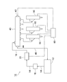
- FIG. 1 is a configuration diagram showing a schematic configuration of a common rail system provided with a fuel supply pump according to an embodiment of the present invention. It is a longitudinal cross-sectional view which shows the structure of the fuel supply pump by embodiment of this invention. It is a longitudinal cross-sectional view which shows an example of a structure of the cylinder and plunger in the fuel supply pump shown in FIG. It is a longitudinal cross-sectional view which shows the other example of a structure of the cylinder and plunger in the fuel supply pump shown in FIG. It is a longitudinal cross-sectional view which shows the structure of the cylinder and plunger in the fuel supply pump of a prior art as a comparison object. It is a table
- surface which shows the characteristic of the material of members, such as a cylinder and a plunger used with the fuel supply pump by embodiment of this invention, and the fuel supply pump of a prior art.
- FIG. 1 to 6 are views showing a fuel supply pump according to the present embodiment and a common rail system provided with the fuel supply pump.
- FIG. 1 is a configuration diagram showing a schematic configuration of a common rail system provided with a fuel supply pump according to the present embodiment
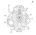
- FIG. 2 is a longitudinal section showing a configuration of the fuel supply pump according to the present embodiment
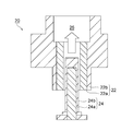
- 3 and 4 are longitudinal sectional views showing various examples of the configuration of the cylinder and the plunger in the fuel supply pump shown in FIG.
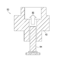
- FIG. 5 is a longitudinal sectional view showing the configuration of a cylinder and a plunger in a conventional fuel supply pump as a comparison object.
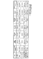
- FIG. 6 is a table showing characteristics of materials of members such as a cylinder and a plunger used in the fuel supply pump according to the present embodiment and the fuel supply pump of the prior art.
- the common rail system 10 includes a fuel tank 12, a fuel supply pump 20 that pressurizes fuel sent from the fuel tank 12 to generate high-pressure fuel, and a high-pressure fuel generated by the fuel supply pump 20.
- the rail 40 is a pressure accumulating chamber for accumulating pressure, and the injector 50 for injecting the high-pressure fuel sent from the rail 40 into each cylinder of the diesel engine.
- the common rail system 10 is provided with an ECU (engine control unit) 60, and the ECU 60 controls the fuel supply pump 20, the rail 40, the injector 50, and the like.
- the fuel sent from the fuel tank 12 is made high-pressure by the fuel supply pump 20, and this high-pressure fuel is stored in the rail 40, and is controlled from the injector 50 to the diesel under the control of the ECU 60.
- An appropriate amount of high pressure fuel is injected into each cylinder of the engine.
- fuel can be finely divided by a high fuel injection pressure, and by reducing the fuel particle, there is no unburned residue in the center of the fuel particle, and the particulate matter Occurrence can be suppressed.
- a fuel supply pipe 14 is provided between the fuel tank 12 and the fuel supply pump 20, and fuel is sent from the fuel tank 12 to the fuel supply pump 20 through the fuel supply pipe 14. It has become.
- the fuel supply pipe 14 is provided with a fuel filter 16, and impurities and the like contained in the fuel sent from the fuel tank 12 are removed by the fuel filter 16.
- a high-pressure fuel supply pipe 18 is provided between the fuel supply pump 20 and the rail 40, and high-pressure fuel that is high pressure fuel by the fuel supply pump 20 is sent to the rail 40 through the high-pressure fuel supply pipe 18. And is stored in the rail 40.
- a fuel pressure sensor 42 is provided in the rail 40 that is a pressure accumulation chamber, and the pressure of the high-pressure fuel in the rail 40 is detected by the fuel pressure sensor 42. .
- Information related to the detection result by the fuel pressure sensor 42 is sent to the ECU 60.
- the rail 40 is provided with a pressure limiter 44, and the pressure of the high-pressure fuel in the rail 40 detected by the fuel pressure sensor 42 is set to a predetermined pressure (limit pressure) preset based on the pressure resistance of the rail 40. ),
- the pressure limiter 44 is mechanically opened, and the high-pressure fuel in the rail 40 is discharged by the pressure limiter 44 and returned to the fuel tank 12 by the fuel return pipe 46.
- a plurality of injectors 50 are connected to the rail 40, and the high-pressure fuel in the rail 40 is supplied to each injector 50.
- Each injector 50 injects high-pressure fuel supplied from the rail 40 into each cylinder of the diesel engine.
- FIG. 2 is a longitudinal sectional view showing the configuration of the fuel supply pump 20 according to the present embodiment
- FIGS. 3 and 4 show the cylinder 22 and the plunger 24 in the fuel supply pump 20 shown in FIG.
- FIG. 2 is a longitudinal cross-sectional view which shows the various examples of a structure.
- the fuel supply pump 20 according to the present embodiment has a cylinder 22 and a plunger 24 that reciprocates in the vertical direction in FIGS. 2 to 4 within the cylinder 22.
- the plunger 24 reciprocates in the vertical direction in FIGS. 2 to 4 in the cylinder 22 so that the fuel is pressurized in the pressurizing chamber 26 provided in the upper part of the fuel supply pump 20. It has become.
- an eccentric cam 30 is provided below the plunger 24 in the housing 34 of the fuel supply pump 20.
- the eccentric cam 30 is formed in a columnar shape extending in a direction orthogonal to the paper surface of FIG. 2 and is rotated by a drive shaft 35.
- the central axis of the eccentric cam 30 is eccentric with respect to the central axis of the drive shaft 35.
- a cam ring 32 that revolves around the drive shaft 35 without rotating is provided on the outer periphery of the eccentric cam 30.
- the cam ring 32 has a substantially quadrangular prism shape, and a cylindrical through hole 33 is formed in the cam ring 32.
- the eccentric cam 30 is inserted into the through hole 33 so as to be movable relative to the cam ring 32 in the circumferential direction while the outer wall surface of the eccentric cam 30 and the inner wall surface of the through hole 33 are in contact with each other. Further, the end of the plunger 24 on the cam ring 32 side is always pressed against one of the four planes of the cam ring 32 by a biasing means (not shown).
- the eccentric cam 30 is rotationally driven, the cam ring 32 revolves around the central axis of the drive shaft 35 without rotating about the central axis of the eccentric cam 30. As the cam ring 32 revolves in this way, the plunger 24 reciprocates in the cylinder 22 in the vertical direction in FIGS. 2 to 4.
- a suction adjustment valve 36 is provided on the fuel suction side of the fuel supply pump 20, and the flow rate of fuel sent from the fuel supply pipe 14 to the fuel supply pump 20 is controlled by the suction adjustment valve 36. It has come to be adjusted.
- a high-pressure fuel discharge port 38 is provided on the fuel discharge side of the fuel supply pump 20, and high-pressure fuel generated by pressurizing the fuel by the plunger 24 in the fuel chamber 26 is discharged from the high-pressure fuel discharge port 38. It is discharged and sent to the high-pressure fuel supply pipe 18.
- a ceramic member 24a is disposed on at least the outer surface of the plunger 24 (specifically, the side surface of the plunger 24). More specifically, in the example of the fuel supply pump 20 shown in FIG. 3, the plunger 24 is entirely composed of a ceramic member 24a. In the example of the fuel supply pump 20 shown in FIG. 4, the plunger 24 is formed by combining a ceramic member 24a on the outer surface of a columnar base portion made of a steel material 24b.
- composite the ceramic member 24a means that a ceramic material is combined with the outer surface of the base portion made of the steel material 24b to form a bulk ceramic member 24a having a thickness of several millimeters. That means.
- a ceramic coating such as CrN.
- the film thickness is about several microns, there is a problem that the film is easily peeled off because a large shear stress is generated on the film when the pump is operated as the common rail pressure increases.
- a bulk ceramic member 24a which is thicker than the coating film and difficult to peel off and which has a strong shearing force.
- the composite method include mechanical bonding, joining, shrink fitting, press fitting, and cast-in.
- the interface strength due to thermal stress is required, so in order to maintain the strength, the surface of the ceramic member 24a to be composited is roughened to provide an anchor effect. It can be increased, coated with an active metal, or an intermediate material added to grade the thermal expansion. Note that, among the above-described composite methods, a cast-in is particularly preferable.
- the ceramic member 24a disposed on at least the outer surface of the plunger 24 can be manufactured by various ceramic forming methods.
- various ceramic forming methods there are mold molding, CIP molding (rubber press molding), extrusion molding, injection molding, casting molding, and gel cast molding.
- processing may be performed after molding or baking.
- gel cast molding is particularly preferable.
- the gel cast molding means that a ceramic slurry containing ceramic powder, a dispersion medium and a gelling agent is formed in a molding space of the mold (a space for filling the slurry and molding, a space having the same shape as a desired ceramic molded body). ), And the ceramic slurry is cured and dried to obtain a ceramic molded body.
- the ceramic member 24a When the ceramic member 24a is formed by such gel casting, the ceramic slurry is poured into the forming space of the forming die and hardened as it is, so that a complicated shape can be formed as it is, and the density distribution varies or deforms. The advantage that it is difficult to occur is obtained. Furthermore, gel cast molding is advantageous in that it can be molded into a complex shape, thus reducing the processing cost of hard ceramics. As shown in FIG. 4, the ceramic member 24 a may be disposed not only on the side surface of the plunger 24 but also on the upper surface.
- sialon (SiAlON), alumina (Al 2 O 3 ), stabilized zirconia (ZrO 2 ), silicon carbide (SiC), or nitride is used as the ceramic member 24 a disposed on at least the outer surface of the plunger 24.
- Silicon (Si 3 N 4 ) is used. The characteristics of such materials of sialon (SiAlON), alumina (Al 2 O 3 ), stabilized zirconia (ZrO 2 ), silicon carbide (SiC), and silicon nitride (Si 3 N 4 ) will be described later.
- the ceramic member 22 a is also disposed on at least the inner surface of the cylinder 22. More specifically, like the plunger 24, the cylinder 22 is formed by combining a ceramic member 22a on the inner surface of a base portion made of a steel material 22b.
- composite the ceramic member 22a means that the ceramic material is combined with the inner surface of the base portion made of the steel material 22b to form a bulk ceramic member 22a having a thickness of several millimeters. That means. Examples of the composite method include mechanical bonding, joining, shrink fitting, press fitting, and cast-in.
- the interface strength due to thermal stress is required.
- the surface of the ceramic member 22a to be compounded is roughened to provide an anchor effect. It can be increased, coated with an active metal, or an intermediate material added to grade the thermal expansion. Note that, among the above-described composite methods, a cast-in is particularly preferable.
- the ceramic member 22a disposed on at least the inner surface of the cylinder 22 can be manufactured by various ceramic forming methods.
- various ceramic forming methods there are mold molding, CIP molding (rubber press molding), extrusion molding, injection molding, casting molding, and gel cast molding.
- processing may be performed after molding or baking.
- gel cast molding is preferable.
- the ceramic member 22a is formed by gel casting, the ceramic slurry is poured into the forming space of the forming die and hardened as it is, so that a complicated shape can be formed as it is and the density distribution varies.
- gel cast molding is advantageous in that it can be molded into a complex shape, thereby reducing the processing cost of hard ceramics.
- the ceramic member 24 a in the plunger 24 is at least a portion facing the inner surface of the cylinder 22, more specifically, the cylinder 22. It comes to be disposed at a location facing the ceramic member 22a disposed on the inner surface.
- the ceramic member 22a disposed on at least the inner surface of the cylinder 22 may be made of the same material as the ceramic member 24a disposed on at least the outer surface of the plunger 24, or may be made of a material different from the ceramic member 24a. It may be. Specifically, when the ceramic member 22 a disposed on at least the inner surface of the cylinder 22 is made of the same material as the ceramic member 24 a disposed on at least the outer surface of the plunger 24, these ceramic members are used.
- sialon (SiAlON), alumina (Al 2 O 3 ), stabilized zirconia (ZrO 2 ), silicon carbide (SiC), or silicon nitride (Si 3 N 4 ) is used as the member 22a and the ceramic member 24a.
- the ceramic member 24a of the plunger 24 is provided. Is preferably made of a material having a hardness higher than that of the ceramic member 22a of the cylinder 22. Since the plunger 24 that pressurizes the fuel in the pressurizing chamber 26 by reciprocating in the cylinder 22 is more easily worn than the cylinder 22, as the ceramic member 24 a disposed on at least the outer surface of the plunger 24, This is because a material with higher hardness is required.
- silicon carbide (SiC) having a hardness of 2200 Hv is used as the material of the ceramic member 24 a disposed on at least the outer surface of the plunger 24, and the ceramic member 22 a disposed on at least the inner surface of the cylinder 22.
- silicon nitride (Si 3 N 4 ) whose hardness is 1400 Hv or sialon (SiAlON) whose hardness is 1600 Hv may be used.
- the configuration of the cylinder 82 and the plunger 84 in the conventional fuel supply pump 80 is shown in FIG. Also in the conventional fuel supply pump 80 as shown in FIG. 5, the plunger 84 reciprocates in the vertical direction in FIG. 5 in the cylinder 82, so that the inside of the pressurizing chamber 86 provided at the upper part of the fuel supply pump 80.
- the plunger 84 is made of alloy tool steel (SKD) or the like, and the cylinder 82 is made of forged steel or the like.
- the material of the plunger 84 or the cylinder 82 is a metal material such as alloy tool steel or forged steel, such a metal material has low hardness and Young's modulus and low corrosion resistance compared to a ceramic member, Further, since the coefficient of thermal expansion is large, when the common rail system 10 is increased in pressure (that is, when high pressure fuel having a higher pressure is generated in the fuel supply pump 80), pressure deformation or temperature expansion of the metal material is caused. The gap (clearance) between the plunger 84 and the cylinder 82 increases due to wear loss during long-time use, and the pump efficiency may decrease due to fuel leakage or the like.
- the material such as the plunger 84 or the cylinder 82 is a metal material
- an aluminum alloy as a material for the plunger 84 and the cylinder 82. Even in such a case, when the pressure of the common rail system 10 is increased. In addition, there is a problem that the aluminum alloy is not satisfactory in strength.
- ceramic members are used as the material of the plunger 24 and the cylinder 22.
- the ceramic member when the hardness and Young's modulus of the ceramic member are relatively large, the corrosion resistance is high, and the thermal expansion coefficient is relatively small, when the common rail system 10 is increased in pressure (that is, in the fuel supply pump 20).
- the ceramic member When an attempt is made to produce a high-pressure fuel with a higher pressure), the ceramic member is less susceptible to pressure deformation, temperature expansion, wear loss during long-time use, and the like, and can be given corrosion resistance to the fuel.
- a change in the gap (clearance) between the plunger 24 and the cylinder 22 is suppressed, and thus a decrease in pump efficiency due to fuel leakage or the like can be suppressed.
- the ceramic members 24 a and 22 a are not always necessary to dispose the ceramic members 24 a and 22 a on at least the outer surface of the plunger 24 and at least the inner surface of the cylinder 22. If the ceramic member 22a can be disposed on at least the inner surface of the cylinder 22, when the pressure of the common rail system 10 is increased, pressure deformation, temperature expansion, wear loss, etc. of the ceramic member 22a of the cylinder 22 hardly occur. Therefore, it is possible to suppress a change in the gap (clearance) between the plunger 24 and the cylinder 22, and thus it is possible to suppress a decrease in pump efficiency due to fuel leakage or the like.
- the table of FIG. 6 is used for the characteristics of silicon carbide (SiC), sialon (SiAlON), silicon nitride (Si 3 N 4 ), alumina (Al 2 O 3 ) and stabilized zirconia (ZrO 2 ) used as materials. I will explain. As shown in the table of FIG.
- the Young's modulus of silicon carbide (SiC), sialon (SiAlON), and silicon nitride (Si 3 N 4 ) is sufficiently larger than the Young's modulus of aluminum alloys and steels. Even when the pressure is increased, silicon carbide (SiC), sialon (SiAlON), and silicon nitride (Si 3 N 4 ) are less susceptible to pressure deformation than aluminum alloys and steel.
- the hardness of silicon carbide (SiC), sialon (SiAlON), silicon nitride (Si 3 N 4 ), alumina (Al 2 O 3 ) and stabilized zirconia (ZrO 2 ) is sufficiently higher than the hardness of aluminum alloys and steels Even when the fuel supply pumps 20, 80 are used for a long time, silicon carbide (SiC), sialon (SiAlON), silicon nitride (Si 3 N 4 ), alumina (Al 2 O 3 ), and stabilized zirconia (ZrO) As for 2 ), the wear loss at the time of long time use is suppressed rather than aluminum alloy and steel.
- the clearance (clearance) between the plunger 24 and the cylinder 22 is, for example, ⁇ 1 to 2 ⁇ m or less. It can be maintained, and a decrease in pump efficiency due to fuel leakage or the like can be suppressed.
- the ceramic member 24a of the plunger 24 is provided. Even if silicon carbide (SiC) is used as the material for the cylinder and silicon nitride (Si 3 N 4 ) or sialon (SiAlON) is used as the material for the ceramic member 22a of the cylinder 22, the difference in expansion due to temperature change between the two Therefore, even when a temperature change occurs in the fuel supply pump 20, it is possible to suppress a change in the gap (clearance) between the plunger 24 and the cylinder 22.
- Example 1 Using a die simulating the members arranged on the inner surface of the plunger 24 and the cylinder 22 for the diesel high pressure fuel pump shown in FIG. 3, slurry containing silicon nitride powder is injected into the die, and molding is performed by gel cast molding. The body was made. Thereafter, the formed body was fired in a nitrogen atmosphere to obtain a densified silicon nitride fired body. Next, only the portion inserted into the inner surface of the cylinder 22 was obtained for the obtained plunger 24, and only the inner surface into which the plunger 24 was inserted was applied to the cylinder 22 to optimize the clearance amount between both members.
- the cylinder 22 was subjected to pre-heat treatment before casting after placing the above-mentioned fired body of silicon nitride in a cast iron casting mold. Then, cast iron melted in a mold was cast, and the sample of cylinder 22 in which silicon nitride and cast iron were combined was produced by controlling cooling while casting the aforementioned sintered body of silicon nitride.
- FCD450 JIS standard
- FCD450 JIS standard
- Example 5 Samples in which the inner surface of the cylinder 22 and the plunger 24 were formed of sialon, stabilized zirconia, silicon carbide, and alumina, respectively, instead of silicon nitride were produced by the same method as in Example 1 above.
- Example 6 Using a die simulating the members arranged on the inner surface of the plunger 24 and the cylinder 22 for the diesel high pressure fuel pump shown in FIG. 4, a slurry containing silicon nitride powder is injected into the die and molded by gel casting. The body was made. Thereafter, the formed body was fired in a nitrogen atmosphere to obtain a densified silicon nitride fired body. Next, only the portion inserted into the inner surface of the cylinder 22 was obtained for the obtained plunger 24, and only the inner surface into which the plunger 24 was inserted was applied to the cylinder 22 to optimize the clearance amount between both members.
- the above-mentioned silicon nitride fired body was placed in a cast iron casting mold, and then pre-heat treatment before casting was performed. Then, cast iron melted in a mold was cast, and the above-mentioned sintered body of silicon nitride was controlled and cooled, so that a sample of plunger 24 in which silicon nitride was compounded on the outer peripheral surface of cast iron was produced.
- the cylinder 22 was subjected to pre-heat treatment before casting after the fired body of silicon nitride described above was placed in a mold for cast iron casting. Then, cast iron melted in a mold was cast, and the sample of cylinder 22 in which silicon nitride and cast iron were combined was produced by controlling cooling while casting the aforementioned sintered body of silicon nitride.
- FCD450 JIS standard
- FCD450 JIS standard
- Example 7 Samples in which the inner surface of the cylinder 22 and the outer peripheral surface of the plunger 24 were formed of sialon, stabilized zirconia, silicon carbide, and alumina, respectively, instead of silicon nitride were prepared by the same method as in Example 6 above.
- Example 11 A sample in which the inner surface of the cylinder 22 and the material of the plunger 24 were changed as shown in Table 1 by the same method as in Example 1 was prepared.
- Characteristic evaluation test 1 As an evaluation for simulating the amount of fuel leakage during use, the amount of liquid fuel leakage was evaluated under pressurized (200 to 400 MPa) and non-pressurized cycle conditions.
- Characteristic evaluation test 2 As an evaluation for simulating the wear resistance during use, a frictional wear test under pressure was performed for a long time while dropping fuel, and the amount of thinning due to wear before and after the test was investigated.
- ⁇ and ⁇ indicate the case where liquid fuel does not leak in the characteristic evaluation test 1 described above and the amount of thinning due to wear is small in the characteristic evaluation test 2 described above.
- the case where the liquid fuel leaks or the case where the thinning amount due to wear is large in the characteristic evaluation test 2 is indicated by “ ⁇ ” and “X”.
- the ceramic member 22a is disposed on at least the inner surface of the cylinder 22, so that the cylinder 22 can be obtained by the high Young's modulus of the ceramic member 22a. Since the ceramic member 22a has a small coefficient of thermal expansion, the cylinder 22 has a small amount of expansion due to temperature change, and the ceramic member 22a has a high hardness and is not easily worn. Wear loss is suppressed even when used for a long time. And because of these advantages, deformation of the cylinder 22 prevents the gap (clearance) between the plunger 24 and the cylinder 22 from increasing, and thus the occurrence of fuel leakage and the like is suppressed.
- the fuel efficiency of the vehicle equipped with the common rail system 10 according to the present embodiment can be improved, and the amount of exhaust gas such as CO 2 and NO X can be reduced. Further, as compared with the case where a metal material such as an aluminum alloy or steel is used as the plunger 84 as in the conventional fuel supply pump 80, the fuel supply pump 20 can be reduced in size and long-term durability. Become.
- the ceramic member 24a is also provided on at least the outer surface of the plunger 24 that pressurizes the fuel in the pressurizing chamber 26 by reciprocating in the cylinder 22. Is arranged. Accordingly, due to the high Young's modulus of the ceramic member 24a, the plunger 24 is not easily deformed by pressure, and since the ceramic member 24a has a small coefficient of thermal expansion, the plunger 24 also has a small amount of expansion due to temperature change, and the ceramic member Since the manufactured member 24a is hard and difficult to wear, the wear loss is suppressed even if the plunger 24 is used for a long time.
- the ceramic member 24a is disposed on at least the outer surface of the plunger 24.
- the ceramic member 22a is disposed on the inner surface of the cylinder 22.
- a fuel supply pump in which the ceramic member 24a is not disposed on at least the outer surface of the plunger 24 may be used.
- the ceramic member 22a disposed on at least the inner surface of the cylinder 22 is another type of member constituting the cylinder 22, specifically, It is combined with a metal material such as a steel material 22b.
- the ceramic member 22a is combined with other types of members constituting the cylinder 22 by mechanical bonding, joining, shrink fitting, press-fitting, or casting. This makes it possible to obtain a bulk ceramic member 22a that is thicker than the coating film and strong against shearing force.
- the ceramic member 22a is formed by die molding, CIP molding, extrusion molding, injection molding, cast molding, or gel cast molding.
- the ceramic slurry is poured into the forming space of the forming die and hardened as it is, so that a complicated shape can be formed according to the shape, and the density distribution varies or deforms.
- the advantage that it is difficult to occur is obtained.
- gel cast molding is advantageous in that it can be molded into a complex shape, thus reducing the processing cost of hard ceramics.
- the ceramic member 24a disposed on at least the outer surface of the plunger 24 is also combined with other types of members constituting the plunger 24, specifically, a metal material such as a steel material 24b. It is good also as what was made.
- the ceramic member 24a may be combined with other types of members constituting the plunger 24 by mechanical bonding, bonding, shrink fitting, press-fitting, or casting.
- the ceramic member 24a may be formed by die molding, CIP molding, extrusion molding, injection molding, cast molding, or gel cast molding.
- the ceramic member 24 a is disposed at a location facing at least the inner surface of the cylinder 22.
- the clearance (clearance) between the plunger 24 and the cylinder 22 that causes fuel leakage is based on the distance between the outer surface of the plunger 24 and the inner surface of the cylinder 22.
- the fuel supply pump 20 of the present embodiment having the above-described configuration when used, the occurrence of fuel leakage or the like is suppressed even when the common rail system 10 is increased in pressure, so the fuel of the common rail system 10
- the injection pressure can be 200 MPa or higher, more preferably 250 MPa or higher.
- the fuel supply pump 20 according to the present embodiment is not limited to the above-described mode, and various changes can be made.
- the ceramic member 24 a disposed on at least the outer surface of the plunger 24 and the ceramic member 22 a disposed on at least the inner surface of the cylinder 22 silicon carbide (SiC), sialon (SiAlON), silicon nitride
- SiC silicon carbide
- SiAlON sialon
- Si nitride silicon carbide
- other types of ceramic materials may be used as long as their Young's modulus is 200 GPa or more. . Even in this case, the Young's modulus of the ceramic material is sufficiently large, and even when the common rail system 10 is increased in pressure, the ceramic material is less susceptible to pressure deformation than a metal material such as an aluminum alloy or steel.
- the hardness of the ceramic member 24a disposed on at least the outer surface of the plunger 24 and the ceramic member 22a disposed on at least the inner surface of the cylinder 22 is 1000 Hv or more, other types of ceramic materials May be used. Even in this case, the hardness of the ceramic material is sufficiently large, and even when the fuel supply pump 20 is used for a long time, the ceramic material is less susceptible to wear loss than a metal material such as an aluminum alloy or steel.
Landscapes
- Engineering & Computer Science (AREA)
- Mechanical Engineering (AREA)
- General Engineering & Computer Science (AREA)
- Fuel-Injection Apparatus (AREA)
- Details Of Reciprocating Pumps (AREA)
Abstract
燃料供給ポンプ20は、シリンダ22と、シリンダ22内で往復移動を行うことにより加圧室26内で燃料を加圧するプランジャ24と、を備えており、シリンダ22の少なくとも内面にセラミック製部材22aが配設されている。
Description
本発明は、燃料を加圧して吐出する燃料供給ポンプに関する。
従来から、ディーゼルエンジンの燃料噴射装置としてコモンレールシステムを用いたものが知られている。コモンレールシステムとは、燃料タンクから送られた燃料を燃料供給ポンプで高圧にし、この高圧燃料をレール(蓄圧室)内に蓄え、ECU(エンジンコントロールユニット)による制御のもとにタイミングよくインジェクタから各気筒に適切な噴射量の高圧燃料を噴射するシステムのことをいう。このようなコモンレールシステムによれば、高い燃料噴射圧力により、燃料を微粒することができ、燃料の粒が小さくなることにより当該燃料の粒の中心部の燃え残りがなくなり粒子状物質の発生を抑えることができるようになる。特開2000-320450号公報や特表2004-518901号公報には、コモンレールシステムで用いられる燃料供給ポンプの様々な例が開示されている。
近年では、CO2やNOX等の排ガス量を低減するために、コモンレールシステムにおける高圧化が行われており、コモンレールシステムの燃料噴射圧力は現状で約200MPaであるところ将来的には約350~400MPa程度まで増加することが見込まれている。しかしながら、コモンレールシステムの高圧化を行った際に、燃料供給ポンプを構成するプランジャやシリンダ等の材料がアルミニウム合金や鉄鋼等の金属材料である場合には、この金属材料の圧力変形や温度膨張、摩耗ロス等によりプランジャとシリンダとの間の隙間(クリアランス)が大きくなってしまい、燃料漏れ等によりポンプ効率が低下してしまうおそれがある。さらに、燃料供給ポンプを構成するプランジャやシリンダ等の材料が金属材料である場合には、高圧条件下での燃料に対する耐食性の問題も生じてしまう。
また、特開平2-227553号公報には、燃料供給ポンプにおいてプランジャの表面に低温下で無電解ニッケルメッキ皮膜を形成し、このニッケルメッキ皮膜中に金属酸化物や金属炭化物等の硬質微粒子を分散析出させる技術が開示されている。また、特開平8-109884号公報には、油圧ポンプにおいてカムとプランジャとの間に窒化珪素等のセラミック材料からなるボールを配設した技術が開示されている。また、特開平11-311164号公報には、内燃機関の高圧燃料装置において所定値よりも大きい熱膨張係数および所定値よりも大きい硬度を有する高熱膨張、高硬度のセラミック材料によりプランジャを形成した技術が開示されている。また、特開2001-50137号公報には、燃料供給ポンプにおいて一体構成されたセラミックによりプランジャを形成した技術が開示されている。また、特開2009-191731号公報には、燃料ポンプにおいてプランジャの外周面にセラミック層を形成した技術が開示されている。しかしながら、上述した様々な技術をもってしても、シリンダの材料がアルミニウム合金や鉄鋼等の金属材料である場合には、この金属材料の圧力変形や温度膨張、摩耗ロス等によりプランジャとシリンダとの間の隙間(クリアランス)が大きくなってしまい、燃料漏れ等によりポンプ効率が低下してしまうという問題を解決することができなかった。また、シリンダの材料が金属材料である場合には、高圧条件下での燃料に対する耐食性の問題も生じてしまう。
本発明は、このような点を考慮してなされたものであり、プランジャとシリンダとの間の隙間(クリアランス)が大きくなってしまうことが抑制され、よって燃料漏れ等の発生が抑制されることにより、コモンレールシステムを高圧化してもポンプ効率が低下してしまうことを防止することができる燃料供給ポンプを提供することを目的とする。
本発明の燃料供給ポンプは、シリンダと、前記シリンダ内で往復移動を行うことにより加圧室内で燃料を加圧するプランジャと、を備え、前記シリンダの少なくとも内面にセラミック製部材が配設されていることを特徴とする。
本発明の燃料供給ポンプにおいては、前記シリンダの少なくとも内面に配設された前記セラミック製部材は、前記シリンダを構成する他の種類の部材と複合化されたものであってもよい。
この場合、前記シリンダの少なくとも内面に配設された前記セラミック製部材は、前記シリンダを構成する金属材料と複合化されたものであってもよい。
また、前記セラミック製部材は、機械的結合、接合、焼きばめ、圧入または鋳ぐるみされることにより前記シリンダを構成する他の種類の部材と複合化されていてもよい。
また、前記セラミック製部材は、金型成形、CIP成形、押出し成形、射出成形、鋳込み成形またはゲルキャスト成形により成形されたものであってもよい。
なお、本発明において用いられるゲルキャスト成形としては、特開2010-192889号公報、特開2011-046002号公報、特開2011-134537号公報等に開示される方法が用いられるようになっている。
本発明の燃料供給ポンプにおいては、前記プランジャの少なくとも外面にもセラミック製部材が配設されていてもよい。
この際に、前記プランジャの少なくとも外面に配設された前記セラミック製部材は、前記プランジャを構成する他の種類の部材と複合化されたものであってもよい。
この場合、前記プランジャの少なくとも外面に配設された前記セラミック製部材は、前記プランジャを構成する金属材料と複合化されたものであってもよい。
また、前記セラミック製部材は、機械的結合、接合、焼きばめ、圧入または鋳ぐるみされることにより前記プランジャを構成する他の種類の部材と複合化されていてもよい。
また、前記セラミック製部材は、金型成形、CIP成形、押出し成形、射出成形、鋳込み成形またはゲルキャスト成形により成形されたものであってもよい。
本発明の燃料供給ポンプにおいては、前記プランジャにおいて、前記セラミック製部材は、少なくとも前記シリンダの内面に対向する箇所に配設されていてもよい。
また、前記シリンダの少なくとも内面に配設された前記セラミック製部材は、前記プランジャの少なくとも外面に配設された前記セラミック製部材と同じ材料からなっていてもよい。
この場合、前記シリンダの少なくとも内面に配設された前記セラミック製部材および前記プランジャの少なくとも外面に配設された前記セラミック製部材として、それぞれサイアロン、アルミナ、安定化ジルコニア、炭化珪素または窒化珪素が用いられてもよい。
あるいは、前記シリンダの少なくとも内面に配設された前記セラミック製部材は、前記プランジャの少なくとも外面に配設された前記セラミック製部材と異なる材料からなっていてもよい。
この場合、前記プランジャの少なくとも外面に配設された前記セラミック製部材の材料は、前記シリンダの少なくとも内面に配設された前記セラミック製部材の材料よりも硬度が大きなものからなっていてもよい。
また、前記プランジャの少なくとも外面に配設された前記セラミック製部材の材料として炭化珪素が用いられるとともに、前記シリンダの少なくとも内面に配設された前記セラミック製部材の材料としてサイアロンまたは窒化珪素が用いられてもよい。
本発明の燃料供給ポンプにおいては、前記シリンダの少なくとも内面に配設された前記セラミック製部材として、そのヤング率が200GPa以上のものが用いられてもよい。
また、前記プランジャの少なくとも外面に配設された前記セラミック製部材の材料として、そのヤング率が200GPa以上のものが用いられてもよい。
また、前記シリンダの少なくとも内面に配設された前記セラミック製部材として、その硬度が1000Hv以上のものが用いられてもよい。
また、前記プランジャの少なくとも外面に配設された前記セラミック製部材の材料として、その硬度が1000Hv以上のものが用いられてもよい。
また、前記燃料供給ポンプが設けられたコモンレールシステムの燃料噴射圧力が200MPa以上であってもよい。
この場合、前記燃料供給ポンプが設けられたコモンレールシステムの燃料噴射圧力が250MPa以上であってもよい。
以下、図面を参照して本発明の実施の形態について説明する。図1乃至図6は、本実施の形態に係る燃料供給ポンプやこの燃料供給ポンプが設けられたコモンレールシステムを示す図である。このうち、図1は、本実施の形態による燃料供給ポンプが設けられたコモンレールシステムの概略の構成を示す構成図であり、図2は、本実施の形態による燃料供給ポンプの構成を示す縦断面図であり、図3および図4は、図2に示す燃料供給ポンプにおけるシリンダおよびプランジャの構成の様々な例を示す縦断面図である。また、図5は、比較対象として、従来技術の燃料供給ポンプにおけるシリンダおよびプランジャの構成を示す縦断面図である。また、図6は、本実施の形態による燃料供給ポンプや従来技術の燃料供給ポンプで用いられるシリンダやプランジャ等の部材の材料の特性を示す表である。
本実施の形態に係る燃料供給ポンプを説明するにあたり、まず、この燃料供給ポンプが設けられたコモンレールシステムの構成について図1を用いて説明する。図1に示すように、コモンレールシステム10は、燃料タンク12と、燃料タンク12から送られた燃料を加圧して高圧燃料を生成する燃料供給ポンプ20と、燃料供給ポンプ20により生成された高圧燃料を蓄圧する蓄圧室であるレール40と、レール40から送られた高圧燃料をディーゼルエンジンの各気筒に噴射するためのインジェクタ50とを備えている。また、コモンレールシステム10にはECU(エンジンコントロールユニット)60が設けられており、このECU60により燃料供給ポンプ20、レール40、インジェクタ50等の制御が行われるようになっている。このようなコモンレールシステム10では、燃料タンク12から送られた燃料が燃料供給ポンプ20で高圧にされ、この高圧燃料がレール40内に蓄えられ、ECU60による制御のもとにタイミングよくインジェクタ50からディーゼルエンジンの各気筒に適切な噴射量の高圧燃料が噴射されるようになっている。そして、このようなコモンレールシステム10によれば、高い燃料噴射圧力により、燃料を微粒することができ、燃料の粒が小さくなることにより当該燃料の粒の中心部の燃え残りがなくなり粒子状物質の発生を抑えることができるようになる。
図1に示すようなコモンレールシステム10について以下に詳しく説明する。図1に示すように、燃料タンク12と燃料供給ポンプ20との間には燃料供給管14が設けられており、この燃料供給管14により燃料タンク12から燃料供給ポンプ20に燃料が送られるようになっている。また、燃料供給管14には燃料フィルタ16が設けられており、この燃料フィルタ16により、燃料タンク12から送られた燃料に含まれる不純物等が除去されるようになっている。また、燃料供給ポンプ20とレール40との間には高圧燃料供給管18が設けられており、燃料供給ポンプ20により高圧にされた燃料である高圧燃料が高圧燃料供給管18によりレール40に送られ、当該レール40内に蓄えられるようになっている。
また、図1に示すように、蓄圧室であるレール40には燃料圧力センサ42が設けられており、この燃料圧力センサ42によりレール40内の高圧燃料の圧力が検出されるようになっている。燃料圧力センサ42による検知結果に係る情報はECU60に送られるようになっている。また、レール40にはプレッシャーリミッタ44が設けられており、燃料圧力センサ42により検出されたレール40内の高圧燃料の圧力が、当該レール40の耐圧に基づいて予め設定された所定圧(限界圧)を超えると、プレッシャーリミッタ44が機械的に開弁し、レール40内の高圧燃料が当該プレッシャーリミッタ44により排出されて燃料戻し管46により燃料タンク12に戻されるようになっている。
また、図1に示すように、レール40には複数のインジェクタ50が接続されており、レール40内の高圧燃料は各インジェクタ50に供給されるようになっている。そして、各インジェクタ50は、レール40から供給された高圧燃料をディーゼルエンジンの各気筒に噴射するようになっている。
次に、このようなコモンレールシステム10に設けられた燃料供給ポンプ20の構成の詳細について図2乃至図4を用いて説明する。前述したように、図2は、本実施の形態による燃料供給ポンプ20の構成を示す縦断面図であり、図3および図4は、図2に示す燃料供給ポンプ20におけるシリンダ22およびプランジャ24の構成の様々な例を示す縦断面図である。図2に示すように、本実施の形態による燃料供給ポンプ20は、シリンダ22と、シリンダ22内で図2乃至図4における上下方向に往復移動を行うプランジャ24とを有している。ここで、シリンダ22内でプランジャ24が図2乃至図4における上下方向に往復移動を行うことにより、燃料供給ポンプ20の上部に設けられた加圧室26内で燃料が加圧されるようになっている。
また、燃料供給ポンプ20のハウジング34内においてプランジャ24の下方には偏心カム30が設けられている。偏心カム30は図2の紙面に直交する方向に延びる円柱状に形成され、駆動軸35により回転させられるようになっている。ここで、図2に示すように、偏心カム30の中心軸は、駆動軸35の中心軸に対して偏心している。また、偏心カム30の外周には、駆動軸35の周りを自転せずに公転するカムリング32が設けられている。カムリング32は外形が略四角柱形状であり、当該カムリング32には円筒状の貫通孔33が形成されている。この貫通孔33には、偏心カム30が、当該偏心カム30の外壁面と貫通孔33の内壁面とが接しながらカムリング32と周方向に相対移動可能に挿入されている。また、プランジャ24におけるカムリング32側の端部は、図示しない付勢手段にて、カムリング32における四平面うちの一面に常に押し付けられている。そして、偏心カム30が回転駆動すると、カムリング32は偏心カム30の中心軸周りを自転せずに、駆動軸35の中心軸周りを公転する。このようにカムリング32が公転することにより、プランジャ24はシリンダ22内を図2乃至図4における上下方向に往復移動するようになる。
また、図2に示すように、燃料供給ポンプ20における燃料吸入側には吸入調整弁36が設けられており、燃料供給管14から燃料供給ポンプ20に送られる燃料の流量が吸入調整弁36により調整されるようになっている。また、燃料供給ポンプ20における燃料吐出側には高圧燃料吐出口38が設けられており、燃料室26においてプランジャ24により燃料が加圧されることにより生成された高圧燃料が高圧燃料吐出口38から吐出されて高圧燃料供給管18に送られるようになっている。
図2に示す燃料供給ポンプ20におけるシリンダ22およびプランジャ24の構成の詳細を図3および図4にそれぞれ示す。本実施の形態では、プランジャ24の少なくとも外面(具体的には、プランジャ24の側面)にセラミック製部材24aが配設されている。より詳細には、図3に示す燃料供給ポンプ20の例では、プランジャ24が全体的にセラミック製部材24aにより構成されている。また、図4に示す燃料供給ポンプ20の例では、プランジャ24は、鉄鋼材料24bからなる円柱形状の基体部分の外面にセラミック製部材24aを複合化することにより形成されている。ここで、プランジャ24において「セラミック製部材24aを複合化する」とは、鉄鋼材料24bからなる基体部分の外面にセラミック材料を組み合わせ、数ミリの厚さのバルク状のセラミック製部材24aを形成することをいう。従来のポンプでは、金属製のプランジャ本体にCrN等のセラミックスコーティングの表面処理をして、耐磨耗性の向上や、プランジャとシリンダの焼付け防止をすることが検討されている。しかしながら、セラミックスコーティングの場合、その膜厚は数ミクロン程度であるため、コモンレール圧力の増大に伴い、ポンプ稼動時に膜に対して大きなせん断応力が発生するため、膜が剥がれ易くなるという問題がある。このため、コーティング膜よりも膜厚が厚くて剥離し難くせん断力に強いバルク状のセラミック製部材24aを複合化することが望ましい。複合化する手法としては、機械的結合、接合、焼きばめ、圧入、鋳ぐるみ等が挙げられる。ここで、セラミック製部材24aを複合化する場合、熱応力による界面強度が要求されるため、その強度を維持するために、セラミック製部材24aの複合化する表面を、粗面にしてアンカー効果を高めたり、活性金属をコーティングしたり、中間材を追加して熱膨張を傾斜化することも可能である。なお、前記の複合化手法の中では、特に鋳ぐるみが好ましい。
また、本実施の形態では、プランジャ24の少なくとも外面に配設されたセラミック製部材24aは、各種のセラミックス成形方法で製造可能である。例えば、金型成形、CIP成形(ラバープレス成形)、押出し成形、射出成形、鋳込み成形、ゲルキャスト成形がある。前記成形方法において、成形や焼成後に加工を施しても良い。なお、前記成形方法の中では、特にゲルキャスト成形が好ましい。ここで、ゲルキャスト成形とは、セラミック粉体、分散媒およびゲル化剤を含むセラミックスラリーを成形型の成形空間(スラリーを充填して成形するための空間、所望のセラミック成形体と同形の空間)に投入し、投入されたセラミックスラリーを硬化・乾燥して、セラミック成形体を得る方法のことをいう。このようなゲルキャスト成形によりセラミック製部材24aを成形した場合には、成形型の成形空間にセラミックスラリーを流し込んでそのまま固められるので、複雑な形状も型通りに成形でき、密度分布のバラつきや変形が起こりにくくなるという利点が得られる。更に、ゲルキャスト成形では、複雑形状への成形が可能となるため、硬質なセラミックスの加工コストを抑える点でも利点がある。なお、図4に示すように、セラミック製部材24aはプランジャ24の側面のみならず上面にも配設されていてもよい。
本実施の形態では、プランジャ24の少なくとも外面に配設されたセラミック製部材24aとして、サイアロン(SiAlON)、アルミナ(Al2O3)、安定化ジルコニア(ZrO2)、炭化珪素(SiC)または窒化珪素(Si3N4)が用いられるようになっている。このようなサイアロン(SiAlON)、アルミナ(Al2O3)、安定化ジルコニア(ZrO2)、炭化珪素(SiC)、窒化珪素(Si3N4)の材料の特徴については後述する。
また、本実施の形態では、シリンダ22の少なくとも内面にもセラミック製部材22aが配設されている。より詳細には、プランジャ24と同様に、シリンダ22は、鉄鋼材料22bからなる基体部分の内面にセラミック製部材22aを複合化することにより形成されている。ここで、シリンダ22において「セラミック製部材22aを複合化する」とは、鉄鋼材料22bからなる基体部分の内面にセラミック材料を組み合わせ、数ミリの厚さのバルク状のセラミック製部材22aを形成することをいう。複合化する手法としては、機械的結合、接合、焼きばめ、圧入、鋳ぐるみ等が挙げられる。ここで、セラミック製部材22aを複合化する場合、熱応力による界面強度が要求されるため、その強度を維持するために、セラミック製部材22aの複合化する表面を、粗面にしてアンカー効果を高めたり、活性金属をコーティングしたり、中間材を追加して熱膨張を傾斜化することも可能である。なお、前記の複合化手法の中では、特に鋳ぐるみが好ましい。
また、本実施の形態では、シリンダ22の少なくとも内面に配設されたセラミック製部材22aは、各種のセラミックス成形方法で製造可能である。例えば、金型成形、CIP成形(ラバープレス成形)、押出し成形、射出成形、鋳込み成形、ゲルキャスト成形がある。前記成形方法において、成形や焼成後に加工を施しても良い。なお、前記成形方法の中では、ゲルキャスト成形が好ましい。前述したように、ゲルキャスト成形によりセラミック製部材22aを成形した場合には、成形型の成形空間にセラミックスラリーを流し込んでそのまま固められるので、複雑な形状も型通りに成形でき、密度分布のバラつきや変形が起こりにくくなるという利点が得られ、また、ゲルキャスト成形では、複雑形状への成形が可能となるため、硬質なセラミックスの加工コストを抑える点でも利点がある。また、シリンダ22の少なくとも内面にもセラミック製部材22aが配設されている場合には、プランジャ24において、セラミック製部材24aは、少なくともシリンダ22の内面に対向する箇所、より詳細にはシリンダ22の内面に配設されたセラミック製部材22aに対向する箇所に配設されるようになる。
シリンダ22の少なくとも内面に配設されたセラミック製部材22aは、プランジャ24の少なくとも外面に配設されたセラミック製部材24aと同じ材料からなっていてもよく、あるいは当該セラミック製部材24aと異なる材料からなっていてもよい。具体的には、シリンダ22の少なくとも内面に配設されたセラミック製部材22aが、プランジャ24の少なくとも外面に配設されたセラミック製部材24aと同じ材料からなっている場合には、これらのセラミック製部材22aおよびセラミック製部材24aとしてそれぞれサイアロン(SiAlON)、アルミナ(Al2O3)、安定化ジルコニア(ZrO2)、炭化珪素(SiC)または窒化珪素(Si3N4)が用いられる。
また、シリンダ22の少なくとも内面に配設されたセラミック製部材22aが、プランジャ24の少なくとも外面に配設されたセラミック製部材24aと異なる材料からなっている場合には、プランジャ24のセラミック製部材24aはシリンダ22のセラミック製部材22aよりも硬度が大きなものからなっていることが好ましい。シリンダ22内で往復移動を行うことにより加圧室26内で燃料を加圧するプランジャ24の方がシリンダ22よりも摩耗しやすいため、プランジャ24の少なくとも外面に配設されたセラミック製部材24aとして、より高硬度の材料が求められるからである。例えば、プランジャ24の少なくとも外面に配設されたセラミック製部材24aの材料としてその硬度が2200Hvである炭化珪素(SiC)が用いられるとともに、シリンダ22の少なくとも内面に配設されたセラミック製部材22aの材料としてその硬度が1400Hvである窒化珪素(Si3N4)やその硬度が1600Hvであるサイアロン(SiAlON)が用いられてもよい。ここで、後述するように、炭化珪素(SiC)と窒化珪素(Si3N4)やサイアロン(SiAlON)との間で熱膨張係数に大きな差がないため、プランジャ24のセラミック製部材24aの材料として炭化珪素(SiC)を用いるとともにシリンダ22のセラミック製部材22aの材料として窒化珪素(Si3N4)サイアロン(SiAlON)を用いても、両者の間で温度変化による膨張量の差は小さく、このため燃料供給ポンプ20において温度変化が生じた場合でも、プランジャ24とシリンダ22との間の隙間(クリアランス)が変化してしまうことを抑制することができる。
次に、比較対象として、従来技術の燃料供給ポンプ80におけるシリンダ82およびプランジャ84の構成を図5に示す。図5に示すような従来技術の燃料供給ポンプ80でも、シリンダ82内でプランジャ84が図5における上下方向に往復移動を行うことにより、燃料供給ポンプ80の上部に設けられた加圧室86内で燃料が加圧されるようになるが、プランジャ84は合金工具鋼(SKD)等から形成されているとともにシリンダ82は鍛造鋼等から形成されている。しかしながら、プランジャ84やシリンダ82の材料が合金工具鋼や鍛造鋼等の金属材料である場合には、このような金属材料はセラミック製部材と比較して硬度やヤング率が小さいとともに耐食性が低く、また熱膨張係数が大きいため、コモンレールシステム10の高圧化を行った際に(すなわち、燃料供給ポンプ80において圧力がより大きな高圧燃料を生成しようとした場合)、この金属材料の圧力変形や温度膨張、長時間使用時の摩耗ロス等によりプランジャ84とシリンダ82との間の隙間(クリアランス)が大きくなってしまい、燃料漏れ等によりポンプ効率が低下してしまうおそれがある。更に、プランジャ84やシリンダ82等の材料が金属材料である場合には、高圧条件下での燃料に対する耐食性の問題も生じてしまう。また、従来技術の燃料供給ポンプ80において軽量化を図るためにプランジャ84やシリンダ82の材料としてアルミニウム合金を用いることも考えられるが、このような場合でも、コモンレールシステム10の高圧化を行った際に、アルミニウム合金では強度的に満足しないという問題がある。
これに対して、本実施の形態の燃料供給ポンプ20では、プランジャ24やシリンダ22の材料としてセラミック製部材が用いられている。ここで、セラミック製部材の硬度やヤング率は比較的大きいとともに耐食性が高く、また熱膨張係数が比較的小さいことにより、コモンレールシステム10の高圧化を行った際に(すなわち、燃料供給ポンプ20において圧力がより大きな高圧燃料を生成しようとした場合)、セラミック製部材は圧力変形や温度膨張、長時間使用時の摩耗ロス等が生じにくくなるとともに燃料に対する耐食性を付与することができる。このことにより、プランジャ24とシリンダ22との間の隙間(クリアランス)が変化してしまうことが抑制され、よって燃料漏れ等によるポンプ効率の低下を抑制することができる。
なお、本実施の形態の燃料供給ポンプ20では、必ずしもプランジャ24の少なくとも外面およびシリンダ22の少なくとも内面に両方にセラミック製部材24a、22aを配設する必要はない。シリンダ22の少なくとも内面にセラミック製部材22aを配設することができれば、コモンレールシステム10の高圧化を行った際に、シリンダ22のセラミック製部材22aの圧力変形や温度膨張、摩耗ロス等が生じにくくなるためプランジャ24とシリンダ22との間の隙間(クリアランス)が変化してしまうことが抑制され、よって燃料漏れ等によるポンプ効率の低下を抑制することができるようになる。
従来技術の燃料供給ポンプ80においてプランジャ84やシリンダ82の材料として用いられるアルミニウム合金および鉄鋼、ならびに本実施の形態の燃料供給ポンプ20においてプランジャ24のセラミック製部材24aやシリンダ22のセラミック製部材22aの材料として用いられる炭化珪素(SiC)、サイアロン(SiAlON)、窒化珪素(Si3N4)、アルミナ(Al2O3)および安定化ジルコニア(ZrO2)の材料の特性について図6の表を用いて説明する。図6の表に示すように、炭化珪素(SiC)、サイアロン(SiAlON)、窒化珪素(Si3N4)のヤング率はアルミニウム合金や鉄鋼のヤング率よりも十分に大きいため、コモンレールシステム10の高圧化を行った場合でも、炭化珪素(SiC)、サイアロン(SiAlON)、窒化珪素(Si3N4)はアルミニウム合金や鉄鋼よりも圧力変形しにくくなる。また、炭化珪素(SiC)、サイアロン(SiAlON)、窒化珪素(Si3N4)、アルミナ(Al2O3)および安定化ジルコニア(ZrO2)の硬度はアルミニウム合金や鉄鋼の硬度よりも十分に大きいため、燃料供給ポンプ20、80を長時間使用した場合でも、炭化珪素(SiC)、サイアロン(SiAlON)、窒化珪素(Si3N4)、アルミナ(Al2O3)および安定化ジルコニア(ZrO2)はアルミニウム合金や鉄鋼よりも長時間使用時の摩耗ロスが抑制される。また、炭化珪素(SiC)、サイアロン(SiAlON)、窒化珪素(Si3N4)およびアルミナ(Al2O3)の熱膨張係数はアルミニウム合金や鉄鋼の熱膨張係数よりも十分に小さいため、燃料供給ポンプ20、80において温度変化が生じた場合でも、炭化珪素(SiC)、サイアロン(SiAlON)、窒化珪素(Si3N4)およびアルミナ(Al2O3)はアルミニウム合金や鉄鋼よりも熱膨張しにくくなる。このため、従来技術と比較して、本願発明の燃料供給ポンプ20ではコモンレールシステム10の高圧化を行った場合、プランジャ24とシリンダ22との間の隙間(クリアランス)を例えば±1~2μm以下に維持することができ、燃料漏れ等によるポンプ効率の低下を抑制することができるようになる。
また、図6の表に示すように、炭化珪素(SiC)、サイアロン(SiAlON)、窒化珪素(Si3N4)の間で熱膨張係数に大きな差がないため、プランジャ24のセラミック製部材24aの材料として炭化珪素(SiC)を用いるとともにシリンダ22のセラミック製部材22aの材料として窒化珪素(Si3N4)やサイアロン(SiAlON)を用いても、両者の間で温度変化による膨張量の差は小さく、このため燃料供給ポンプ20において温度変化が生じた場合でも、プランジャ24とシリンダ22との間の隙間(クリアランス)が変化してしまうことを抑制することができる。
次に、本実施の形態による燃料供給ポンプ20の実施例について下記の表1を用いて説明する。
(実施例1)
図3に示すディーゼル用高圧燃料ポンプ向けのプランジャ24およびシリンダ22の内面にそれぞれ配置する部材を模擬した金型を用い、そこに窒化珪素粉末を含んだスラリーを注入し、ゲルキャスト成形にて成形体を作製した。その後、作製された成形体を窒素雰囲気中で焼成し、緻密化した窒化珪素の焼成体を得た。次に、得られたプランジャ24についてはシリンダ22内面に挿入される部分のみ、またシリンダ22についてはプランジャ24が挿入される内面のみ表面加工を施し、両部材間のクリアランス量を最適化した。
図3に示すディーゼル用高圧燃料ポンプ向けのプランジャ24およびシリンダ22の内面にそれぞれ配置する部材を模擬した金型を用い、そこに窒化珪素粉末を含んだスラリーを注入し、ゲルキャスト成形にて成形体を作製した。その後、作製された成形体を窒素雰囲気中で焼成し、緻密化した窒化珪素の焼成体を得た。次に、得られたプランジャ24についてはシリンダ22内面に挿入される部分のみ、またシリンダ22についてはプランジャ24が挿入される内面のみ表面加工を施し、両部材間のクリアランス量を最適化した。
その後、シリンダ22については、鋳鉄鋳造用の金型中に前述の窒化珪素の焼成体を配置した後、鋳造前の予熱処理を行なった。そして、金型中に溶解した鋳鉄を鋳造し、前述の窒化珪素の焼成体を鋳ぐるみながら制御冷却することで窒化珪素と鋳鉄とが複合化されたシリンダ22のサンプルを作製した。なお、鋳ぐるみ用に使用した鋳鉄には球状黒鉛鋳鉄として知られるFCD450(JIS規格)材を選定した。
(実施例2~5)
上記の実施例1と同様な方法にて、シリンダ22の内面やプランジャ24を窒化珪素ではなくサイアロン、安定化ジルコニア、炭化珪素、アルミナでそれぞれ形成したようなサンプルを作製した。
上記の実施例1と同様な方法にて、シリンダ22の内面やプランジャ24を窒化珪素ではなくサイアロン、安定化ジルコニア、炭化珪素、アルミナでそれぞれ形成したようなサンプルを作製した。
(実施例6)
図4に示すディーゼル用高圧燃料ポンプ向けのプランジャ24およびシリンダ22の内面にそれぞれ配置する部材を模擬した金型を用い、そこに窒化珪素粉末を含んだスラリーを注入し、ゲルキャスト成形にて成形体を作製した。その後、作製された成形体を窒素雰囲気中で焼成し、緻密化した窒化珪素の焼成体を得た。次に、得られたプランジャ24についてはシリンダ22内面に挿入される部分のみ、またシリンダ22についてはプランジャ24が挿入される内面のみ表面加工を施し、両部材間のクリアランス量を最適化した。
図4に示すディーゼル用高圧燃料ポンプ向けのプランジャ24およびシリンダ22の内面にそれぞれ配置する部材を模擬した金型を用い、そこに窒化珪素粉末を含んだスラリーを注入し、ゲルキャスト成形にて成形体を作製した。その後、作製された成形体を窒素雰囲気中で焼成し、緻密化した窒化珪素の焼成体を得た。次に、得られたプランジャ24についてはシリンダ22内面に挿入される部分のみ、またシリンダ22についてはプランジャ24が挿入される内面のみ表面加工を施し、両部材間のクリアランス量を最適化した。
その後、プランジャ24については、鋳鉄鋳造用の金型中に前述の窒化珪素の焼成体を配置した後、鋳造前の予熱処理を行なった。そして、金型中に溶解した鋳鉄を鋳造し、前述の窒化珪素の焼成体を鋳ぐるみながら制御冷却することで、鋳鉄の外周面に窒化珪素が複合化されたプランジャ24のサンプルを作製した。
また、シリンダ22については、鋳鉄鋳造用の金型中に前述の窒化珪素の焼成体を配置した後、鋳造前の予熱処理を行なった。そして、金型中に溶解した鋳鉄を鋳造し、前述の窒化珪素の焼成体を鋳ぐるみながら制御冷却することで窒化珪素と鋳鉄とが複合化されたシリンダ22のサンプルを作製した。なお、鋳ぐるみ用に使用した鋳鉄には球状黒鉛鋳鉄として知られるFCD450(JIS規格)材を選定した。
(実施例7~10)
上記の実施例6と同様な方法にて、シリンダ22の内面やプランジャ24の外周面を窒化珪素ではなくサイアロン、安定化ジルコニア、炭化珪素、アルミナでそれぞれ形成したようなサンプルを作製した。
上記の実施例6と同様な方法にて、シリンダ22の内面やプランジャ24の外周面を窒化珪素ではなくサイアロン、安定化ジルコニア、炭化珪素、アルミナでそれぞれ形成したようなサンプルを作製した。
(実施例11~13)
上記の実施例1と同様な方法にて、シリンダ22の内面やプランジャ24の材料を下記の表1に示すように変えたようなサンプルを作製した。
上記の実施例1と同様な方法にて、シリンダ22の内面やプランジャ24の材料を下記の表1に示すように変えたようなサンプルを作製した。
(比較例1)
図5に示すディーゼル用高圧燃料ポンプ向けのプランジャ84とシリンダ82として、CrNコーティングされたSKD鋼と鍛造鋼を用い、サンプルを作製した。
図5に示すディーゼル用高圧燃料ポンプ向けのプランジャ84とシリンダ82として、CrNコーティングされたSKD鋼と鍛造鋼を用い、サンプルを作製した。
〔評価方法〕
上記の実施例1~13、及び比較例1により得られたサンプルを用い、特性評価として以下の2種類の評価を行った。この2種類の評価結果をまとめたものを表1に示す。
上記の実施例1~13、及び比較例1により得られたサンプルを用い、特性評価として以下の2種類の評価を行った。この2種類の評価結果をまとめたものを表1に示す。
特性評価試験1:使用時の燃料漏れ量を模擬する評価として、加圧(200~400MPa)と無加圧のサイクル条件での液体燃料の漏れ量の評価を行った。
特性評価試験2:使用時の耐摩耗性を模擬する評価として、燃料を滴下しながら、加圧下での摩擦磨耗試験を長期間行い、試験前後での磨耗に伴う減肉量を調査した。
下記の表1では、上述した特性評価試験1において液体燃料の漏れが生じず、かつ、上述した特性評価試験2において摩耗に伴う減肉量が少ない場合を「◎」「○」で示し、一方、特性評価試験1において液体燃料の漏れが生じてしまった場合や、特性評価試験2において摩耗に伴う減肉量が多い場合を「△」「×」で示している。

表1に示すように、比較例1の金属材料を用いたものでは、特性評価試験1では圧力による弾性変形が生じ、圧力を上げると共に、燃料漏れ量の増加傾向を示した。また、特性評価試験2では、圧力を上げると共に、比較例1では硬質CrNによって相手材の鉄鋼側での磨耗減肉が起こったのに対し、セラミックスを用いた場合では磨耗減肉は少ないものであった。
以上のような構成からなる本実施の形態の燃料供給ポンプ20によれば、シリンダ22の少なくとも内面にセラミック製部材22aが配設されていることにより、セラミック製部材22aの高ヤング率によってシリンダ22は圧力により変形し難くなり、また、セラミック製部材22aは熱膨張係数が小さいためシリンダ22は温度変化による膨張量も小さくなり、しかもセラミック製部材22aは硬度が大きく摩耗しにくいためシリンダ22は長時間使用しても摩耗ロスが抑制される。そして、これらの利点により、シリンダ22が変形することによりプランジャ24と当該シリンダ22との間の隙間(クリアランス)が大きくなってしまうことが抑制され、よって燃料漏れ等の発生が抑制されるので、コモンレールシステム10を高圧化してもポンプ効率が低下してしまうことを防止することができる。このことにより、本実施の形態によるコモンレールシステム10が搭載された車両の燃費を向上させることができ、またCO2やNOX等の排ガス量を低減することができるようになる。また、従来技術の燃料供給ポンプ80のような、プランジャ84としてアルミニウム合金や鉄鋼等の金属材料を用いる場合と比較して、燃料供給ポンプ20の小型化や長期耐久化も図ることができるようになる。
また、本実施の形態の燃料供給ポンプ20においては、前述したように、シリンダ22内で往復移動を行うことにより加圧室26内で燃料を加圧するプランジャ24の少なくとも外面にもセラミック製部材24aが配設されている。このことにより、セラミック製部材24aの高ヤング率によってプランジャ24は圧力により変形し難くなり、また、セラミック製部材24aは熱膨張係数が小さいためプランジャ24は温度変化による膨張量も小さくなり、しかもセラミック製部材24aは硬度が大きく摩耗しにくいためプランジャ24は長時間使用しても摩耗ロスが抑制される。そして、これらの利点により、プランジャ24が変形することにより当該プランジャ24とシリンダ22との間の隙間(クリアランス)が大きくなってしまうことがより一層抑制され、よって燃料漏れ等の発生がより一層抑制されるので、コモンレールシステム10を高圧化してもポンプ効率が低下してしまうことをより一層防止することができる。なお、本発明では、プランジャ24の少なくとも外面にセラミック製部材24aを配設するのはあくまで任意であり、本発明における他の態様として、シリンダ22の内面にセラミック製部材22aが配設されているがプランジャ24の少なくとも外面にセラミック製部材24aが配設されていないような燃料供給ポンプが用いられてもよい。
また、本実施の形態の燃料供給ポンプ20においては、前述したように、シリンダ22の少なくとも内面に配設されたセラミック製部材22aは、シリンダ22を構成する他の種類の部材、具体的には鉄鋼材料22b等の金属材料と複合化されたものとなっている。具体的には、セラミック製部材22aは、機械的結合、接合、焼きばめ、圧入または鋳ぐるみされることによりシリンダ22を構成する他の種類の部材と複合化されている。このことにより、コーティング膜よりも膜厚が厚くてせん断力に強いバルク状のセラミック製部材22aが得られるようになる。また、セラミック製部材22aは、金型成形、CIP成形、押出し成形、射出成形、鋳込み成形またはゲルキャスト成形により成形されたものとなっている。ここで、ゲルキャスト法によりセラミック製部材22aを成形した場合には、成形型の成形空間にセラミックスラリーを流し込んでそのまま固められるので、複雑な形状も型通りに成形でき、密度分布のバラつきや変形が起こりにくくなるという利点が得られる。更に、ゲルキャスト成形では、複雑形状への成形が可能となるため、硬質なセラミックスの加工コストを抑える点でも利点がある。
同様に、図4に示すように、プランジャ24の少なくとも外面に配設されたセラミック製部材24aも、プランジャ24を構成する他の種類の部材、具体的には鉄鋼材料24b等の金属材料と複合化されたものとしてもよい。この場合、セラミック製部材24aは、機械的結合、接合、焼きばめ、圧入または鋳ぐるみされることによりプランジャ24を構成する他の種類の部材と複合化されていてもよい。また、セラミック製部材24aは、金型成形、CIP成形、押出し成形、射出成形、鋳込み成形またはゲルキャスト成形により成形されたものとなっていてもよい。
また、本実施の形態の燃料供給ポンプ20においては、前述したように、プランジャ24において、セラミック製部材24aは、少なくともシリンダ22の内面に対向する箇所に配設されている。ここで、燃料漏れの原因となるプランジャ24とシリンダ22との間の隙間(クリアランス)は、プランジャ24の外面とシリンダ22の内面との間の距離に基づくものであるため、プランジャ24において、少なくともシリンダ22の内面に対向する箇所にセラミック製部材24aを配設することにより、このセラミック製部材24aは前述したように変形しにくくなるため、プランジャ24とシリンダ22との間の隙間が大きくなってしまうことが抑制されるようになる。
また、上述したような構成からなる本実施の形態の燃料供給ポンプ20を用いた場合には、コモンレールシステム10を高圧化しても燃料漏れ等の発生が抑制されるので、当該コモンレールシステム10の燃料噴射圧力を200MPa以上、より好ましくは250MPa以上とすることができるようになる。
なお、本実施の形態による燃料供給ポンプ20は、上述したような態様に限定されることはなく、様々な変更を加えることができる。
例えば、上記説明では、プランジャ24の少なくとも外面に配設されたセラミック製部材24aやシリンダ22の少なくとも内面に配設されたセラミック製部材22aとして、炭化珪素(SiC)やサイアロン(SiAlON)、窒化珪素(Si3N4)を用いた態様について述べたが、これらのセラミック製部材24a、22aの材料として、そのヤング率が200GPa以上のものであれば、他の種類のセラミック材料を用いてもよい。この場合でも、当該セラミック材料のヤング率は十分に大きく、コモンレールシステム10の高圧化を行った場合でも、このセラミック材料はアルミニウム合金や鉄鋼等の金属材料よりも圧力変形しにくくなる。
また、プランジャ24の少なくとも外面に配設されたセラミック製部材24aやシリンダ22の少なくとも内面に配設されたセラミック製部材22aとして、その硬度が1000Hv以上のものであれば、他の種類のセラミック材料を用いてもよい。この場合でも、当該セラミック材料の硬度は十分に大きく、燃料供給ポンプ20を長時間使用した場合でも、このセラミック材料はアルミニウム合金や鉄鋼等の金属材料よりも摩耗ロスが抑制される。
Claims (22)
- シリンダと、
前記シリンダ内で往復移動を行うことにより加圧室内で燃料を加圧するプランジャと、
を備え、
前記シリンダの少なくとも内面にセラミック製部材が配設されている、燃料供給ポンプ。 - 前記シリンダの少なくとも内面に配設された前記セラミック製部材は、前記シリンダを構成する他の種類の部材と複合化されたものである、請求項1記載の燃料供給ポンプ。
- 前記シリンダの少なくとも内面に配設された前記セラミック製部材は、前記シリンダを構成する金属材料と複合化されたものである、請求項2記載の燃料供給ポンプ。
- 前記セラミック製部材は、機械的結合、接合、焼きばめ、圧入または鋳ぐるみされることにより前記シリンダを構成する他の種類の部材と複合化されている、請求項2または3記載の燃料供給ポンプ。
- 前記セラミック製部材は、金型成形、CIP成形、押出し成形、射出成形、鋳込み成形またはゲルキャスト成形により成形されたものである、請求項4記載の燃料供給ポンプ。
- 前記プランジャの少なくとも外面にもセラミック製部材が配設されている、請求項1乃至5のいずれか一項に記載の燃料供給ポンプ。
- 前記プランジャの少なくとも外面に配設された前記セラミック製部材は、前記プランジャを構成する他の種類の部材と複合化されたものである、請求項6記載の燃料供給ポンプ。
- 前記プランジャの少なくとも外面に配設された前記セラミック製部材は、前記プランジャを構成する金属材料と複合化されたものである、請求項7記載の燃料供給ポンプ。
- 前記セラミック製部材は、機械的結合、接合、焼きばめ、圧入または鋳ぐるみされることにより前記プランジャを構成する他の種類の部材と複合化されている、請求項7または8記載の燃料供給ポンプ。
- 前記セラミック製部材は、金型成形、CIP成形、押出し成形、射出成形、鋳込み成形またはゲルキャスト成形により成形されたものである、請求項9記載の燃料供給ポンプ。
- 前記プランジャにおいて、前記セラミック製部材は、少なくとも前記シリンダの内面に対向する箇所に配設されている、請求項6乃至10のいずれか一項に記載の燃料供給ポンプ。
- 前記シリンダの少なくとも内面に配設された前記セラミック製部材は、前記プランジャの少なくとも外面に配設された前記セラミック製部材と同じ材料からなる、請求項6乃至11のいずれか一項に記載の燃料供給ポンプ。
- 前記シリンダの少なくとも内面に配設された前記セラミック製部材および前記プランジャの少なくとも外面に配設された前記セラミック製部材として、それぞれサイアロン、アルミナ、安定化ジルコニア、炭化珪素または窒化珪素が用いられる、請求項12記載の燃料供給ポンプ。
- 前記シリンダの少なくとも内面に配設された前記セラミック製部材は、前記プランジャの少なくとも外面に配設された前記セラミック製部材と異なる材料からなる、請求項6乃至11のいずれか一項に記載の燃料供給ポンプ。
- 前記プランジャの少なくとも外面に配設された前記セラミック製部材の材料は、前記シリンダの少なくとも内面に配設された前記セラミック製部材の材料よりも硬度が大きなものからなる、請求項14記載の燃料供給ポンプ。
- 前記プランジャの少なくとも外面に配設された前記セラミック製部材の材料として炭化珪素が用いられるとともに、前記シリンダの少なくとも内面に配設された前記セラミック製部材の材料としてサイアロンまたは窒化珪素が用いられる、請求項15記載の燃料供給ポンプ。
- 前記シリンダの少なくとも内面に配設された前記セラミック製部材として、そのヤング率が200GPa以上のものが用いられる、請求項1乃至16のいずれか一項に記載の燃料供給ポンプ。
- 前記プランジャの少なくとも外面に配設された前記セラミック製部材の材料として、そのヤング率が200GPa以上のものが用いられる、請求項6乃至16のいずれか一項に記載の燃料供給ポンプ。
- 前記シリンダの少なくとも内面に配設された前記セラミック製部材として、その硬度が1000Hv以上のものが用いられる、請求項1乃至16のいずれか一項に記載の燃料供給ポンプ。
- 前記プランジャの少なくとも外面に配設された前記セラミック製部材の材料として、その硬度が1000Hv以上のものが用いられる、請求項6乃至16のいずれか一項に記載の燃料供給ポンプ。
- 前記燃料供給ポンプが設けられたコモンレールシステムの燃料噴射圧力が200MPa以上である、請求項1乃至20のいずれか一項に記載の燃料供給ポンプ。
- 前記燃料供給ポンプが設けられたコモンレールシステムの燃料噴射圧力が250MPa以上である、請求項21記載の燃料供給ポンプ。
Priority Applications (1)
| Application Number | Priority Date | Filing Date | Title |
|---|---|---|---|
| PCT/JP2013/073764 WO2015033398A1 (ja) | 2013-09-04 | 2013-09-04 | 燃料供給ポンプ |
Applications Claiming Priority (1)
| Application Number | Priority Date | Filing Date | Title |
|---|---|---|---|
| PCT/JP2013/073764 WO2015033398A1 (ja) | 2013-09-04 | 2013-09-04 | 燃料供給ポンプ |
Publications (1)
| Publication Number | Publication Date |
|---|---|
| WO2015033398A1 true WO2015033398A1 (ja) | 2015-03-12 |
Family
ID=52627908
Family Applications (1)
| Application Number | Title | Priority Date | Filing Date |
|---|---|---|---|
| PCT/JP2013/073764 Ceased WO2015033398A1 (ja) | 2013-09-04 | 2013-09-04 | 燃料供給ポンプ |
Country Status (1)
| Country | Link |
|---|---|
| WO (1) | WO2015033398A1 (ja) |
Citations (4)
| Publication number | Priority date | Publication date | Assignee | Title |
|---|---|---|---|---|
| JPS58146879U (ja) * | 1982-03-30 | 1983-10-03 | 日産自動車株式会社 | 燃料噴射ポンプ |
| JP2008298061A (ja) * | 2007-06-04 | 2008-12-11 | Usui Kokusai Sangyo Kaisha Ltd | コモンレールおよびその製造方法 |
| JP2009191731A (ja) * | 2008-02-14 | 2009-08-27 | Denso Corp | ポンプ用プランジャおよびその製造方法 |
| JP2010229914A (ja) * | 2009-03-27 | 2010-10-14 | Denso Corp | 高圧ポンプ |
-
2013
- 2013-09-04 WO PCT/JP2013/073764 patent/WO2015033398A1/ja not_active Ceased
Patent Citations (4)
| Publication number | Priority date | Publication date | Assignee | Title |
|---|---|---|---|---|
| JPS58146879U (ja) * | 1982-03-30 | 1983-10-03 | 日産自動車株式会社 | 燃料噴射ポンプ |
| JP2008298061A (ja) * | 2007-06-04 | 2008-12-11 | Usui Kokusai Sangyo Kaisha Ltd | コモンレールおよびその製造方法 |
| JP2009191731A (ja) * | 2008-02-14 | 2009-08-27 | Denso Corp | ポンプ用プランジャおよびその製造方法 |
| JP2010229914A (ja) * | 2009-03-27 | 2010-10-14 | Denso Corp | 高圧ポンプ |
Similar Documents
| Publication | Publication Date | Title |
|---|---|---|
| JP6392232B2 (ja) | 内燃機関 | |
| CN102971517B (zh) | 往复式发动机的气缸衬套 | |
| CN101109347A (zh) | 高压燃料泵 | |
| CN102667077A (zh) | 用于内燃机的排气阀杆及其制造方法 | |
| JP3912206B2 (ja) | 筒内直接燃料噴射装置用燃料ポンプ | |
| US9193000B2 (en) | Metallic component for high-pressure applications | |
| JP6441934B2 (ja) | ポンプ要素 | |
| KR100320698B1 (ko) | 심 및 캠의 조합체 | |
| JPH03229958A (ja) | 内燃機関用クランク軸受部 | |
| JP4329810B2 (ja) | シリンダブロック | |
| JPS58143161A (ja) | 燃料噴射弁 | |
| WO2016037996A1 (en) | Cylinder liner for insertion into an engine block, and engine block | |
| US8523534B2 (en) | High-pressure pump for supplying fuel to an internal-combustion engine | |
| KR101538525B1 (ko) | 연료 공급 시스템의 밸브 유닛 | |
| CN105556108A (zh) | 用于直接燃料喷射的压电喷射器 | |
| JP3565746B2 (ja) | 流体ポンプ | |
| JP4376127B2 (ja) | 減圧鋳造用金型の製造方法 | |
| EP3161177A1 (en) | A coating system and method | |
| JPH11241649A (ja) | シリンダヘッドのノズルホルダ取付構造 | |
| KR100579995B1 (ko) | 자동차용 실린더 블록의 제조방법 | |
| Idzior et al. | Investigation of novel ceramic materials (Al2O3 and SSiC) for high-pressure pumps delivery sections | |
| CN110446845A (zh) | 内燃机的活塞以及内燃机的活塞的制造方法 | |
| CN102239331A (zh) | 共轨式高压泵 | |
| JP2022075382A (ja) | 内燃機関のカムシャフト | |
| US20040224143A1 (en) | Metal-ceramic composite material |
Legal Events
| Date | Code | Title | Description |
|---|---|---|---|
| 121 | Ep: the epo has been informed by wipo that ep was designated in this application |
Ref document number: 13893097 Country of ref document: EP Kind code of ref document: A1 |
|
| NENP | Non-entry into the national phase |
Ref country code: DE |
|
| 122 | Ep: pct application non-entry in european phase |
Ref document number: 13893097 Country of ref document: EP Kind code of ref document: A1 |
|
| NENP | Non-entry into the national phase |
Ref country code: JP |