WO2015032995A1 - Free-electron laser driven by a fibre-based laser feeding a laser plasma accelerator - Google Patents
Free-electron laser driven by a fibre-based laser feeding a laser plasma accelerator Download PDFInfo
- Publication number
- WO2015032995A1 WO2015032995A1 PCT/EP2014/069222 EP2014069222W WO2015032995A1 WO 2015032995 A1 WO2015032995 A1 WO 2015032995A1 EP 2014069222 W EP2014069222 W EP 2014069222W WO 2015032995 A1 WO2015032995 A1 WO 2015032995A1
- Authority
- WO
- WIPO (PCT)
- Prior art keywords
- laser
- electron
- undulator
- free
- pulse
- Prior art date
- Legal status (The legal status is an assumption and is not a legal conclusion. Google has not performed a legal analysis and makes no representation as to the accuracy of the status listed.)
- Ceased
Links
Classifications
-
- H—ELECTRICITY
- H01—ELECTRIC ELEMENTS
- H01S—DEVICES USING THE PROCESS OF LIGHT AMPLIFICATION BY STIMULATED EMISSION OF RADIATION [LASER] TO AMPLIFY OR GENERATE LIGHT; DEVICES USING STIMULATED EMISSION OF ELECTROMAGNETIC RADIATION IN WAVE RANGES OTHER THAN OPTICAL
- H01S3/00—Lasers, i.e. devices using stimulated emission of electromagnetic radiation in the infrared, visible or ultraviolet wave range
- H01S3/09—Processes or apparatus for excitation, e.g. pumping
- H01S3/0903—Free-electron laser
-
- H—ELECTRICITY
- H01—ELECTRIC ELEMENTS
- H01S—DEVICES USING THE PROCESS OF LIGHT AMPLIFICATION BY STIMULATED EMISSION OF RADIATION [LASER] TO AMPLIFY OR GENERATE LIGHT; DEVICES USING STIMULATED EMISSION OF ELECTROMAGNETIC RADIATION IN WAVE RANGES OTHER THAN OPTICAL
- H01S3/00—Lasers, i.e. devices using stimulated emission of electromagnetic radiation in the infrared, visible or ultraviolet wave range
- H01S3/05—Construction or shape of optical resonators; Accommodation of active medium therein; Shape of active medium
- H01S3/06—Construction or shape of active medium
- H01S3/063—Waveguide lasers, i.e. whereby the dimensions of the waveguide are of the order of the light wavelength
- H01S3/067—Fibre lasers
-
- H—ELECTRICITY
- H05—ELECTRIC TECHNIQUES NOT OTHERWISE PROVIDED FOR
- H05G—X-RAY TECHNIQUE
- H05G2/00—Apparatus or processes specially adapted for producing X-rays, not involving X-ray tubes, e.g. involving generation of a plasma
Definitions
- the invention relates to a new embodiment of a Free-Electron Laser ("FEL").
- FEL Free-Electron Laser
- the invention also relates to the use of such a Free-Electron Laser as an Extreme
- EUV Extreme Ultraviolet
- a Free-Electron laser is a type of laser that use a relativistic electron beam that moves freely through a magnetic structure, in order to create a beam consisting of coherent electromagnetic radiation that can reach high power.
- the free electron beam is the lasing medium.
- the free-electron laser has the widest frequency range of any laser type, and can be widely tunable, currently ranging in wavelength from microwaves, through terahertz radiation and infrared, to the visible spectrum, ultraviolet, and X-ray.
- a beam of electrons is accelerated to almost the speed of light.
- the beam passes through the Free-Electron Laser oscillator, a periodic transverse magnetic field produced by an arrangement of magnets with alternating poles within an optical cavity along the beam path.
- This array of magnets is commonly configured as an undulator, because it forces the electrons in the beam to follow a sinusoidal path.
- the acceleration of the electrons along this path results in the release of photons (synchrotron radiation). Since the electron motion is in phase with the field of the light already emitted, the fields add together coherently.
- the wavelength of the light emitted can be readily tuned by adjusting the energy of the electron beam or the magnetic field strength of the undulators.
- a free-electron laser requires the use of an electron accelerator, which is very voluminous, requires a high voltage supply, has a very low repetition rate and is expensive.
- EUV Extreme Ultraviolet
- EUV Extreme UltraViolet
- This technology called as extreme ultraviolet lithography (EUVL) is capable of providing resolution below 30 nm that had been impossible with conventional optical lithography that utilizes deep ultraviolet (DUV) light sources with wavelengths of 248 nm or 193 nm.
- DUV deep ultraviolet
- LPP laser produced plasma
- LPP laser produced plasma
- CO 2 lasers at the wavelength of 10.6 ⁇ provide certain advantages as a drive laser producing main pulses in the laser produced plasma (LPP) process thanks to the ability to produce a relatively high conversion efficiency, i.e., the ratio of output Extreme UltraViolet in-band to drive laser input power.
- the 13.5 nm radiation is collected by a mirror (either grazing incidence or normal incidence) and focused to an intermediate focal point where it is relayed to the scanner optics and, ultimately, the wafer.
- one apparatus currently being developed with the goal of producing about 100 W at the intermediate location contemplates the use of a pulsed, focused 10 - 12 kW CO 2 drive laser which is synchronized with a droplet generator to sequentially irradiate about 40 k - 100 k tin droplets per second.
- a pulsed, focused 10 - 12 kW CO 2 drive laser which is synchronized with a droplet generator to sequentially irradiate about 40 k - 100 k tin droplets per second.
- a relatively high repetition rate e.g. 40 - 100 kHz or more
- deliver the droplets to an irradiation site with high accuracy and good repeatability in terms of timing and position, i.e., with very small jitter, over a relatively long period of time.
- LPP laser produced plasma
- HVM high volume manufacturing
- Free-Electron Laser based radiation sources have evident advantages in wavelength tunability, high efficiency and high output power, compared to current laser produced plasma (LPP) radiation sources.
- LPP laser produced plasma
- the problem of debris mitigation does not exist at all. There is no need to use a multilayer coated reflective collector, of which reflectivity is limited to about 70%, since the radiation is produced in the diffraction limited volume. Hence, there is no problem with the transport of radiation to the exposure system.
- the Free-Electron Laser based Extreme UltraViolet radiation source may have an average output power of 0.5 kW at a repetition rate of at least 250 kHz for meeting the requirements of the light source at 13.5 nm for the next generation lithography.
- a proposed Free-Electron Laser based Free-Electron Laser producing a kW-level average output power of Extreme UltraViolet radiation utilizes high-energy electron beams of the order of 1 GeV generated from a radio-frequency (RF)-based linear accelerator that comprises a high-brightness electron injector typically composed of a photocathode RF gun or thermionic high-voltage DC gun and several buncher cavities for producing electron bunches, a several-stage magnetic bunch compressor system comprising a sequence of RF structure and bending magnets for compressing a bunch length and increasing a peak beam current and a main linac composed of a series of room-temperature or superconducting RF cavities with the accelerating gradient of the order of 10 MV/m and a beam transport system including beam focusing and defocusing electro-quadrupole magnets, lastly followed by undulators with a total length of 30 m, providing alternating magnetic fields to force electrons on a sinusoidal trajectory so that all electrons in a electron bunch emit coherently
- the overall size of a RF linac-driven Free-Electron Laser-based Extreme Ultraviolet light source may require a 250 m long facility for a linac-based light source or a 120 m long, 60 m wide area for a recirculator-based light source.
- the costs for construction and operation of such facility may turn out incredibly so large as to prevent the Free-Electron Laser-based Extreme Ultraviolet light sources from industrial realization of the next generation lithography technology.
- the objective of the present invention is to overcome the cited disadvantages of the prior art.
- an objective of the invention is to provide a new embodiment of Free Electron Laser, more compact and efficient, cheaper and having a higher repetition rate and a higher average power as the prior art Free Electron Lasers .
- Another objective of the invention is to provide an efficient Free-Electron Laser-based Extreme Ultraviolet light source, usable for industrial lithography technology.
- a Free Electron Laser source generating an electromagnetic beam presenting a wavelength, called Free Electron Laser wavelength, belonging to the range from 5nm to 15nm, said Free Electron Laser comprising:
- a fiber-based laser comprising a plurality of amplifying fibres wherein an initial laser pulse is distributed and amplified, and means for grouping together the elementary pulses amplified in the said fibre in order to form an a single amplified global laser pulse, and comprising a stretching device able to stretch out in time said initial laser pulse, according to the chirped pulse amplification technique and a grating pulse compressor able to compress in time the said single amplified global laser pulse, according to the chirped pulse amplification technique,
- said fiber-laser being tuned using at least one parameter, called fiber-based laser parameter, said at least one fiber-based laser parameter being obtained as a function of said Free Electron Laser wavelength;
- a laser plasma accelerator wherein, in a bubble regime of said plasma accelerator said global laser pulse generates relativistic electron beams
- said laser plasma accelerator being tuned using at least one parameter, called laser plasma accelerator parameter, said at least one laser plasma accelerator parameter being obtained as a function of said Free Electron Laser wavelength;
- a beam focusing system transporting electron beams from the laser plasma accelerator to an undulator
- said undulator being tuned using at least one parameter, called undulator parameter, said at least one undulator parameter being obtained as a function of said Free Electron Laser wavelength;
- the tuning of the components of said Free Electron Laser is optimised since at least one parameter of the fiber-based laser (e.g. the average fiber laser power, the required pulse duration, the match spot radius, the peak power, laser energy pulse, etc.), at least one parameter of the laser plasma accelerator (e .g . the electron beam energy , the plasma density , the accelerator length, etc.), and at least one parameter of the undulator (e.g. the Pierce Parameter, the saturation length, the total number of periods, etc .) are all tuned as a function of the Free Electron Laser wavelength, when the peak magnetic field and the period of the undulator have been previously set.
- the fiber-based laser e.g. the average fiber laser power, the required pulse duration, the match spot radius, the peak power, laser energy pulse, etc.
- at least one parameter of the laser plasma accelerator e .g . the electron beam energy , the plasma density , the accelerator length, etc.
- at least one parameter of the undulator e.g. the Pierce Parameter, the saturation
- Wiggins S . M. does not disclose that at least one parameter of the laser plasma accelerator, and at least one parameter of the undulator, are obtained as a function of said Free Electron Laser wavelength.
- the laser disclosed by Tarima which uses optical fibers (as the one according to the present invention), is not designed such that its major parameters depend all on the Free Electron Laser wavelength. Indeed, no FEL is disclosed by Tarima, who discloses only a use of such fiber-based laser to treat nuclear waste.
- the fiber-based laser can emit pulses of very high energy.
- said laser plasma accelerator comprises:
- Such a laser plasma accelerator is very efficient, with a very high repetition rate.
- said laser plasma accelerator comprise means for modifying the length of the said second gas cell.
- the wavelength of the electromagnetic beam emitted by the Free Electron Laser source can then be tuned.
- said beam separator system comprises a dipole magnet for bending electron beams and a beam dump.
- said electromagnetic beam is a Extreme Ultraviolet beam.
- UltraViolet source usable for lithography application.
- Such a Extreme Ultraviolet source is more compact and efficient, cheaper and having a higher repetition rate and a higher average power as the prior art Extreme UltraViolet sources .
- said Extreme UltraViolet beam wavelength is
- said Extreme UltraViolet beam wavelength is 6.7 nm.
- Fig.l shows a schematic diagram of a Free Electron Laser according to an embodiment of the invention, usable as an Extreme UltraViolet light source.
- Fig. 2 illustrates a schematic diagram of a coherent combining fiber-based drive laser used in the Free Electron Laser of Fig. 1.
- Fig. 3 shows the two-stage gas cell plasma accelerator of the Free Electron Laser of Fig. 1.
- Fig. 4 shows the laser plasma electron accelerator system of the Free Electron Laser of Fig. 1 , comprising the gas cell plasma accelerator of Fig. 3.
- Fig. 5 illustrates schematically electron acceleration mechanism due to laser wakefield.
- Fig. 6 shows a schematic view of a miniature permanent magnet quadrupole (PMQ).
- Fig. 7 shows an example of a beam focusing system comprising four permanent magnet quadrupoles (PMQ) of the type represented by Fig 6.
- Fig. 8 shows schematically a planar undulator made of pure permanent magnets producing a vertical field.
- Fig. 9 shows schematically a hybrid planar undulator made of permanent magnets and ferromagnetic material, e.g., iron or cobalt steel.
- Fig. 10A and 10B show a schematic assembly of the undulator used in the Free Electron Laser of Fig. 1.
- Fig. 11 A, 11B and 11C shows a monolithic beam dump system comprising a permanent magnet dipole separating electron beams from Extreme Ultraviolet radiation and a electron beam dump.
- Fig. 12 illustrates a setup of a compact self-amplified spontaneous emission (SASE) Free-Electron Laser system comprising the beam focusing system of Fig. 4, the compact undulator of Fig. 5 and the beam dump system of Fig. 6.
- SASE spontaneous emission
- Fig. 13 illustrates schematically the Extreme Ultraviolet light source of Fig. 1 , based on a compact Free-Electron Laser driven by a fiber laser-based plasma accelerator according to aspects of an embodiment of the present invention
- Fig. 14 illustrates how the parameters of each component constituting the Free-Electron Laser of Fig . 1 , are obtained as a function of the Free-Electron Laser wavelength according to aspects of an embodiment of the present invention
- the proposed Free-Electron Laser may include a drive laser system 1 for generating high energy laser pulses at a high repetition rate of the order of 1 MHz and delivering intense laser pulses 3 compressed through a pulse compressor chamber 2 into a laser plasma accelerator chamber 4.
- a laser-driven Free-Electron Laser can be used as an Extreme Ultraviolet light source.
- Fibre-type laser Figure 2 shows an item of drive laser system 1 for producing high-energy laser pulses .
- a low-energy laser pulse 810 is produced by an oscillator 81.
- This pulse 810 is then stretched out in time, according to the chirped pulse amplification (CPA) technique, by a stretching device 82, comprising a pair of diffraction gratings 821 and 822, having the effect of offsetting in time the various spectral components of the original low- energy pulse 810.
- the stretched pulse 820 then has a lower peak power and a longer duration of the pulse 810.
- This laser pulse 820 is then distributed in a plurality of amplifying fibres 831 forming a first amplifying stage 83 of the fibre-type laser amplifier.
- the various fibres are separated from one another so as to make it possible to cool them effectively.
- Each of the amplifying fibres 831 comprises a core made from doped material, and is optically pumped, so as to optically amplify the laser pulse flowing in the fibre.
- the pulse passing through each of these amplifying fibres 831 is then amplified, and is then itself distributed in a plurality of amplifying fibres 841 forming the second amplification stage 84 of the fibre-type laser amplifier.
- the pulse passing through each of these amplifying fibres 841 is amplified and is then itself distributed in a plurality of amplifying fibres 851 forming the third amplification stage 85 of the fibre-type laser amplifier.
- the pulse is amplified in a plurality of fibres independent of one another and then divided so that pulses of lower power are transmitted to each of the higher- level amplification fibres .
- the third and last amplification stage 85 then comprises a very large number of amplifying fibres , for example around 10 6 .
- Each of the amplifying fibres of this third stage is extended by a transmission fibre having a very low loss level.
- the transmission fibres are collected together in a cluster 86 so that the pulses emerging from each of the ends of these transmission fibres are emitted in parallel and juxtaposed. These pulses then form a single amplified global pulse 860.
- This amplified global pulse 860 is compressed timewise by a compressor 87, located in the pulse compressor chamber 2.
- This compressor 87 comprises a pair of diffraction gratings 871 and 872, grouping together in time the various spectral components of the pulse.
- the pulse 3 emerging from this temporal compressor 17 then has a very high energy and very short duration.
- the ultrashort intense laser pulse 3 is focused by an off-axis parabolic mirror 5 on the entrance of a two-stage gas cell 6, of which the first cell referred to an injector is filled with a mixed gas , e.g., helium gas mixed with nitrogen, and the second cell referred to as an accelerator is filled with a pure gas, e.g., hydrogen or helium.
- a mixed gas e.g., helium gas mixed with nitrogen
- an accelerator e.g., hydrogen or helium.
- the gases are fed through a gas flow control system 7 to the two-stage gas cell separately at the different pressures.
- the said laser pulse 3 excites large- amplitude plasma wakefields, of which an accelerating electric field can trap plasma electrons exclusively out of the inner shell electrons and accelerate them owing to ionization-induced injection.
- a pre-accelerated electron beam 10 from the injector is further accelerated to the relativistic energy of the order of 1 GeV in the accelerator stage of the gas cell 6, where the laser pulse generates plasma wakefields of the order of 1 GV/cm.
- a transmitted laser light is directed through a mirror with a beam hole 8 to a recovery box 9 that includes diagnostics and absorbers of the transmitted laser pulses .
- This plasma accelerator is particularly advantageous when it is combined with a fiber- based laser, a beam focusing system, an undulator and a beam separator system according to the invention.
- a laser plasma accelerator comprising a first gas cell filled with mixed gas, and a second gas cell filled with pure helium gas can also be combined with an other type of laser, for producing relativistic electron beams.
- the output electron beam 10 from the laser plasma accelerator chamber 4 is transported into an undulator 13 through a beam focusing system 12, installed in a radiation chamber 11.
- a beam focusing system 12 installed in a radiation chamber 11.
- the electron beam 10 focused by quadrupole magnetic field of the beam focusing system 12 generates the resonantly amplified Extreme UltraViolet radiation 14 due to self-amplified spontaneous emission (SASE) mechanism when passing through the alternating dipole magnetic fields of the undulator 13 that force the electron bunch on a sinusoidal trajectory.
- SASE self-amplified spontaneous emission
- the electron bunch After passing through the undulator 13 , the electron bunch is decelerated so strongly that it becomes non-resonant and could not contribute to the amplification of the Extreme UltraViolet radiation, i.e., the onset of saturation.
- the decelerated electron beam 10 is separated from the Extreme UltraViolet radiation 14 in the dipole magnetic field of the deflection magnet
- Fig. 3 shows schematically a two-stage gas cell 6 comprising an injector stage 21 and an accelerator stage 24 for efficient electron trapping and acceleration in laser wakefields .
- the two-stage gas cell is set up in a laser plasma accelerator chamber 4 and a compressed laser pulse 3 from the pulse compressor chamber 2 is focused on the entrance of the injector gas cell by an off-axis parabolic mirror 5 with a F-number, e.g., 20.
- the injector cell 21 is filled with a mixed gas, e.g., 98% He and 2% N 2 , fed through a gas feedthrough 20 from the gas flow control system 7.
- the accelerator cell 24 is filled with a pure gas, e.g. H 2 or He, fed through a gas feedthrough 24 from the gas flow control system 7.
- a length of the accelerator stage is variably adjusted with a bellows structure 25 driven by a motorized actuator 26. Such an adjustment can permit to reuse easily the accelerator stage, using said motorized actuator 26, for different Free-Electron laser wavelengths ranging from 5nm to 15nm.
- the laser plasma accelerator chamber 4 is pump out by a vacuum pump system 27 to keep an inside pressure of 10 "3 -10 "4 Pa.
- Fig. 5 illustrates schematically a physical process 100 for the wakefield excitation and electron trapping and acceleration in wakefields , which are generated when an intense laser pulse propagates a neutral mixed gas in the injector 21.
- the evolution of plasma electron density is shown in the upper plot 101 and the excited longitudinal wakefield is shown in the lower plot 102.
- He and the outer shell electrons up to N 5+ are fully ionized in the leading front of the laser pulse with intensity 1.5xl0 16 W/cm 2 to produce plasma electrons in the outer region of the laser pulse, of which the boundary is indicated by a thin dotted line 103.
- 109 indicates the evolution of ionization level of nitrogen (the electron number of ionized nitrogen atom) along the propagation axis .
- a boundary of the plasma region containing the inner shell electrons from ionized N 6+ and N 7+ is indicated by a thin dashed line 104.
- Plasma electrons contained in the boundary 103 are blown out by radiation pressure (ponderomotive force) of the laser pulse 3 with the relativistic intensity a Q » 1 and form a narrow dense electron sheath surrounding a spherical ion column behind the laser pulse, often referred to as a bubble 105.
- radiation pressure ponderomotive force
- a Q » 1 the relativistic intensity
- Such charge separation generates a strong longitudinal electric field
- the said inner shell electrons from ionized N 6+ and N 7+ are located near the bubble center on the propagation axis , where the wake potential is a maximum and the expelling ponderomotive force of the laser pulse is a minimum. Contrary to pre-ionized free electrons, whose trajectories move along a narrow sheath outside the bubble, the ionized electrons emitted from the inner shell move close to the bubble axis toward the back of the bubble where the wake potential is a minimum, and eventually trapped into the wakefield in condition that electrons gain a sufficient kinetic energy required for trapping, as shown in the electron trajectory 106, while the electron shown in the trajectory 107, ionized earlier and off-axis, slips over the potential well and is not trapped.
- This mechanism called as ionization-induced injection occurs at the intensity as low as the optical field ionization threshold for the inner shell electrons of impurity gas and significantly increases the trapped charge.
- amplitudes of the betatron oscillation after trapping decrease compared to the self-injection from the electron sheath.
- the number of trapped electrons scales as N ⁇ / ⁇ 2 1 ⁇ 8 x l0 7 « L (n I n ) m for ⁇ k p L mix ⁇ 2 .
- the maximum energy gain limited due to dephasing is given by
- the operating plasma density is determined by
- the accelerator length is set to be equal to the dephasing length as
- the pulse duration required for satisfying a dephasing length longer than a pump depletion length is T >i8[fs] 2 ( ⁇ ' ljUm )-(- 2 0 ⁇ 0MeV)
- the matched spot radius is given by r g3 .9[/m]- r ⁇ — (- ⁇ -)( * ) 1/2
- the loaded charge is given by ⁇ l - n ITM 1 200MeV L J a r ,, lum 200MeV
- Beam transport and imaging from the laser plasma accelerator 6 to the undulator 13 is provided by a beam focusing system 12 with short focal length.
- Fig. 6 illustrates schematically a twelve segments
- Halbach-type PMQ 31 , 32 of a set of the quadrupole magnet 36 including a housing 33 , 34 and a bracket 35 for supporting and positioning the PMQ.
- the quadrupole field is composed of four radially wedges of permanent magnet material 31 , e.g., Nd 2 Fe 14 B or SmCO , with a high remanent field, of which the direction of magnetization is indicated by arrows .
- the outer field closure is formed by eight wedges of permanent magnet material 32.
- the beam focusing system 12 comprises two to four permanent quadrupole magnets (PMQ), e.g. a doublet (FD) , a triplet (FDF) , or a quadruplet (FFDD) 36-39 installed into a housing chamber 46 with water cooling tubes 44.
- PMQ permanent quadrupole magnets
- the longitudinal position of each permanent quadrupole magnet (PMQ) along the electron beam axis is optimized with a computer controlled mover system 40-43 , comprising a vacuum linear motion manipulator driven by a stepping motor. Alignment of permanent quadrupole magnets (PMQ) is precisely constrained by a rail system 45.
- a planar undulator comprising alternating dipole magnets 52 is used , e .g . , a pure permanent magnet (PPM) undulator with Nd 2 Fe 14 B blocks 50 as shown in Fig . 8 or a hybrid undulator comprising pure permanent magnets 50 and ferromagnetic poles 51 as shown in Fig. 9 , e.g . a high saturation cobalt steel such as vanadium permendur or a simple iron.
- the thickness of the pole and magnet is optimized in order to maximize the peak field.
- the arrows represent the direction of magnetization in the magnet blocks , of which a period is X u .
- the minimum distance between the magnet jaws is a gap g .
- the undulator 13 comprises a rectangular box frame 53 , a gap adjusting mechanism 54 and cooling elements 55.
- the permanent magnet blocks 52 is attached to a thick base plate of the box frame 53 made of aluminium material.
- the alignment and gap of the undulator are adjusted by controlling the distance between two base plates of the box frame 53 with 4 or 6 adjusting mechanisms 54.
- Two monolithic water cooling elements 55 fabricated from tubing are connected to each magnet block 52.
- a decelerated electron beam 10 after saturation is bent by a dipole field of permanent magnet (a beam separator 16) made of NdFeB material and dumped to a beam dump 17 made of copper with a water cooling element 56.
- the permanent magnet dipole (PMD) 16 e.g., Halbach-type permanent magnet dipole, comprises 8 wedges of the NdFeB material, of which the magnetization direction is shown by the arrows in Fig . 11B .
- B r is the tip field strength
- r t is the bore radius
- r 0 is the outer radius of the PMD.
- B 1.45 T for NdFeB material
- B D A3A 1 .
- the mechanical precision and field accuracy of the permanent magnet dipole 16 can be achieved by the insertion of a nonmagnetic precision cylinder 57 into the center of the permanent magnet dipole and by the housing case 58 outside the permanent magnet dipole.
- the electron beam 10 bent by the permanent magnet dipole field 16 is dumped to the copper beam dump 17 , while the Extreme Ultraviolet radiation 14 is extracted through a narrow Extreme Ultraviolet output hole 59 machined in the beam dump 17 at the edge of the permanent magnet dipole bore.
- the Free -Electron Laser device comprising the beam focusing system 12 , the undulator 13 and the beam separator 16 and beam dump 17 is installed into vacuum chambers 1 1 , 15 with vacuum pumping systems 28 , 29 that maintain a pressure of the order of 10 "4 Pa inside the chamber.
- the beam dump 17 connected to the beam separator 16 forms a monolithic device.
- a design of Free-Electron Laser based Extreme UltraViolet light source is made by the one-dimensional Free-Electron Laser theory as follows .
- the Free -Electron Laser amplication takes place in the undulator with the undulator eriod X u at the resonant wavelength given by
- I b is the beam current
- a b is the root mean square (r.m.s) transverse size of the electron bunch
- ⁇ I ⁇ is the relative root mean square (r.m.s .) energy spread
- ⁇ is the r.m.s . transverse emittance
- ⁇ I ⁇ is the beta function provided by the guiding field (undulator plus external focusing)
- ⁇ ⁇ is the normalized emittance defined as ⁇ ⁇ ⁇ assuming that a beta function is constant along the length of the undulator.
- a saturation length L sat required to saturate the am lification can be expressed as
- n and saturated power P sat are related to an electron beam power P b according to sat ⁇ 1.37 AELJ P b exp(-0.82A 2 ) ,
- LP A Laser Plasma Accelerator
- a hybrid undulator comprising NdFeB materials with grade N52 , e.g ., VACODYM® 722HR, and ferromagnetic materials such as tempered Co-Fe alloys (vanadium permendur), e.g., VACOFLUX® 50, provide the peak magnetic field
- LP A Laser Plasma Accelerator
- N 100,72,68,68,69 .
- Peak magnetic field [T] 1.425 1.425 1.425 1.425 1.425 1.425 1.425 1.425 1.425 1.425
- a hybrid undulator comprising NdFeB materials with grade N52, e.g., VACODYM® 722HR, and ferromagnetic materials such as tempered Co-Fe alloys (vanadium permendur), e.g.,
- VACOFLUX® 50 provide the peak magnetic field
- LP A Laser Plasma Accelerator
- I b 50 kA with the number of electrons per wavelength
- N 142,102,96,96,98.
- Plasma density [10 17 cm ⁇ 3 ] 6.5 4.4 3.2 2.5 2.0
- Peak magnetic field [T] 1.425 1.425 1.425 1.425 1.425 1.425 1.425 1.425 1.425 1.425
- the FEL amplification takes place in the undulator with the undulator period ⁇ ⁇ at the resonant wavelength given by
- LP A Laser Plasma Accelerator
- Patent Literature (1) U.S. patent application No. 13/445,195, filed on Apr. 12, 2012, entitled LASER PRODUCED PLASMA EUV LIGHT SOURCE, Pub. No. US 2012/0228526 Al .
Landscapes
- Physics & Mathematics (AREA)
- Electromagnetism (AREA)
- Engineering & Computer Science (AREA)
- Plasma & Fusion (AREA)
- Optics & Photonics (AREA)
- Particle Accelerators (AREA)
- Lasers (AREA)
- Exposure And Positioning Against Photoresist Photosensitive Materials (AREA)
Abstract
The invention concerns a Free Electron Laser-FEL-EUV or Soft-X-Ray light source emitting between 5nm and 15nm comprising : a fiber-based laser (1), encompassing a plurality of amplifying fibres wherein an initial laser pulse is distributed and amplified, and means for grouping together the elementary pulses amplified in the said fibre in order to form an a single amplified global laser pulse (3); a laser plasma accelerator (6) wherein the said global laser pulse (3) generates relativistic electron beams (10), a beam focusing system (12) transporting electron beams (10) from the laser plasma accelerator, an undulator (13) wherein relativistic electron beams (10) generate an electromagnetic beams, and a beam separator system, wherein the said electron beam and the said electromagnetic beam are separated.
Description
FREE-ELECTRON LASER DRIVEN BY A FIBRE-BASED LASER FEEDING A LASER PLASMA
ACCELERATOR
1 Field of the invention
The invention relates to a new embodiment of a Free-Electron Laser ("FEL").
The invention also relates to the use of such a Free-Electron Laser as an Extreme
UltraViolet ("EUV") light sources for Extreme Ultraviolet lithography.
2. Background of the invention
Background of Free-Electron Lasers ("FEL")
A Free-Electron laser (FEL), is a type of laser that use a relativistic electron beam that moves freely through a magnetic structure, in order to create a beam consisting of coherent electromagnetic radiation that can reach high power. In this type of laser, the free electron beam is the lasing medium. The free-electron laser has the widest frequency range of any laser type, and can be widely tunable, currently ranging in wavelength from microwaves, through terahertz radiation and infrared, to the visible spectrum, ultraviolet, and X-ray.
To create a Free-Electron Laser, a beam of electrons is accelerated to almost the speed of light. The beam passes through the Free-Electron Laser oscillator, a periodic transverse magnetic field produced by an arrangement of magnets with alternating poles within an optical cavity along the beam path. This array of magnets is commonly configured as an undulator, because it forces the electrons in the beam to follow a sinusoidal path. The acceleration of the electrons along this path results in the release of photons (synchrotron radiation). Since the electron motion is in phase with the field of the light already emitted, the fields add together coherently. The wavelength of the light emitted can be readily tuned by adjusting the energy of the electron beam or the magnetic field strength of the undulators.
A free-electron laser requires the use of an electron accelerator, which is very voluminous, requires a high voltage supply, has a very low repetition rate and is expensive.
Background of Extreme Ultraviolet ("EUV") light sources
Extreme UltraViolet ("EUV") with wavelengths below about 50 nm and more specifically around and below 13.5 nm can be used in micro lithography processes to enhance the resolution of optical systems that are limited by the diffraction limit of light accompanying miniaturization of semiconductor integrated circuits. This technology called as extreme ultraviolet lithography (EUVL) is capable of providing resolution below 30 nm that had been impossible with conventional optical lithography that utilizes deep ultraviolet (DUV) light sources with wavelengths of 248 nm or 193 nm.
The current technologies for generating high power Extreme UltraViolet radiation at 13.5 nm, referred to as laser produced plasma (LPP), employs the deposition of laser energy into a source element, such as xenon (Xe), tin (Sn) or lithium (Li), creating ionized gas
microplasma at electron temperatures of several tens of electron volts. As these highly excited ions decay, energetic radiation is emitted in all directions of 4π radians.
One particular laser produced plasma (LPP) technique involves irradiating molten tin droplets with one or more pre-pulse(s) followed by a main pulse. In this regard, CO2 lasers at the wavelength of 10.6 μηι provide certain advantages as a drive laser producing main pulses in the laser produced plasma (LPP) process thanks to the ability to produce a relatively high conversion efficiency, i.e., the ratio of output Extreme UltraViolet in-band to drive laser input power.
For Extreme UltraViolet lithography, the 13.5 nm radiation is collected by a mirror (either grazing incidence or normal incidence) and focused to an intermediate focal point where it is relayed to the scanner optics and, ultimately, the wafer.
For example, one apparatus currently being developed with the goal of producing about 100 W at the intermediate location contemplates the use of a pulsed, focused 10 - 12 kW CO2 drive laser which is synchronized with a droplet generator to sequentially irradiate about 40 k - 100 k tin droplets per second. For this purpose, there is a need to produce a stable stream of droplets at a relatively high repetition rate (e.g. 40 - 100 kHz or more) and deliver the droplets to an irradiation site with high accuracy and good repeatability in terms of timing and position, i.e., with very small jitter, over a relatively long period of time.
The current laser produced plasma (LPP) radiation sources have a serious obstacle on the way to a high volume manufacturing (HVM) source such as small efficiency of the radiation source, a limited set of discrete wavelengths and the mitigation of the plasma debris required for the protection of Extreme UltraViolet optics.
Background of Free Electron Laser used as Extreme UltraViolet light sources
Free-Electron Laser based radiation sources have evident advantages in wavelength tunability, high efficiency and high output power, compared to current laser produced plasma (LPP) radiation sources. The problem of debris mitigation does not exist at all. There is no need to use a multilayer coated reflective collector, of which reflectivity is limited to about 70%, since the radiation is produced in the diffraction limited volume. Hence, there is no problem with the transport of radiation to the exposure system. Harnessing such advantages of Free- Electron Laser based Extreme UltraViolet radiation sources liberated from the debris mitigation and a mechanical targeting system such as a droplet generator, the Free-Electron Laser based Extreme UltraViolet radiation source may have an average output power of 0.5 kW at a repetition rate of at least 250 kHz for meeting the requirements of the light source at 13.5 nm for the next generation lithography.
A proposed Free-Electron Laser based Free-Electron Laser producing a kW-level average output power of Extreme UltraViolet radiation utilizes high-energy electron beams of the order of 1 GeV generated from a radio-frequency (RF)-based linear accelerator that
comprises a high-brightness electron injector typically composed of a photocathode RF gun or thermionic high-voltage DC gun and several buncher cavities for producing electron bunches, a several-stage magnetic bunch compressor system comprising a sequence of RF structure and bending magnets for compressing a bunch length and increasing a peak beam current and a main linac composed of a series of room-temperature or superconducting RF cavities with the accelerating gradient of the order of 10 MV/m and a beam transport system including beam focusing and defocusing electro-quadrupole magnets, lastly followed by undulators with a total length of 30 m, providing alternating magnetic fields to force electrons on a sinusoidal trajectory so that all electrons in a electron bunch emit coherently due to the microbunching process, called as self-amplified spontaneous emission (SASE) Free-Electron Laser. The overall size of a RF linac-driven Free-Electron Laser-based Extreme Ultraviolet light source may require a 250 m long facility for a linac-based light source or a 120 m long, 60 m wide area for a recirculator-based light source. The costs for construction and operation of such facility may turn out incredibly so large as to prevent the Free-Electron Laser-based Extreme Ultraviolet light sources from industrial realization of the next generation lithography technology.
3. Objective of the invention
The objective of the present invention is to overcome the cited disadvantages of the prior art.
More specifically, an objective of the invention is to provide a new embodiment of Free Electron Laser, more compact and efficient, cheaper and having a higher repetition rate and a higher average power as the prior art Free Electron Lasers .
Another objective of the invention is to provide an efficient Free-Electron Laser-based Extreme Ultraviolet light source, usable for industrial lithography technology.
4 . Summary of the invention
In order to attain these objectives the present invention provides
A Free Electron Laser source generating an electromagnetic beam presenting a wavelength, called Free Electron Laser wavelength, belonging to the range from 5nm to 15nm, said Free Electron Laser comprising:
a fiber-based laser, comprising a plurality of amplifying fibres wherein an initial laser pulse is distributed and amplified, and means for grouping together the elementary pulses amplified in the said fibre in order to form an a single amplified global laser pulse, and comprising a stretching device able to stretch out in time said initial laser pulse, according to the chirped pulse amplification technique and a grating pulse compressor able to compress in time the said single amplified global laser pulse, according to the chirped pulse amplification technique,
said fiber-laser being tuned using at least one parameter, called fiber-based laser parameter, said at least one fiber-based laser parameter being obtained as a function of
said Free Electron Laser wavelength;
a laser plasma accelerator wherein, in a bubble regime of said plasma accelerator said global laser pulse generates relativistic electron beams,
said laser plasma accelerator being tuned using at least one parameter, called laser plasma accelerator parameter, said at least one laser plasma accelerator parameter being obtained as a function of said Free Electron Laser wavelength;
a beam focusing system transporting electron beams from the laser plasma accelerator to an undulator;
said undulator wherein relativistic electron beams generate an electromagnetic beam, a peak magnetic field and a period of said undulator being previously set,
said undulator being tuned using at least one parameter, called undulator parameter, said at least one undulator parameter being obtained as a function of said Free Electron Laser wavelength;
a beam separator system, wherein the said electron beam and the said electromagnetic beam are separated.
Thanks to the particular combination of the elements constituting said Free Electron Laser, the Free Electron Laser source, or Free Electron Laser, according to the invention is more compact and efficient, cheaper and has a higher repetition rate and a higher average power as the prior art Free Electron Laser sources .
Such a result can only be obtained because of the particular tuning technique implemented according to the present invention. Indeed, as detailed in the following section 6.5 the tuning of the components of said Free Electron Laser is optimised since at least one parameter of the fiber-based laser (e.g. the average fiber laser power, the required pulse duration, the match spot radius, the peak power, laser energy pulse, etc.), at least one parameter of the laser plasma accelerator (e .g . the electron beam energy , the plasma density , the accelerator length, etc.), and at least one parameter of the undulator (e.g. the Pierce Parameter, the saturation length, the total number of periods, etc .) are all tuned as a function of the Free Electron Laser wavelength, when the peak magnetic field and the period of the undulator have been previously set.
Thus, all the essential components of the Free Electron Laser are tuned in synergy as a function of a same parameter, which corresponds to the Free Electron Laser wavelength. Such a relation between all the major parameters of the FEL is not trivial and requires an inventive step.
Such a synergy between the components constituting said Free Electron Laser is neither disclose nor suggest by the prior art, which does not give any concrete solution for designing and implementing a Free Electron Laser whose wavelength belongs to the range from 5nm to
Indeed, considering the disclosure of Wiggins S . M. and al. ("High Quality electron beams from a laser wakefield accelerator" , Conference on Lasers and Electro-Optics (CLEO) and Quantum Electronics and Laser science Conference (QELS), 2010 pages 1-2 XP031701440) , only a classical Laser-Plasma Accelerators towards X-rays combined with a classical undulator are disclosed. Such elements are designed to create an ALPHA-XL WFA line, which could be used for a FEL operation. It has to be noted that such a document discloses only beam transport simulations to illustrate how an FEL laser operating in the VUV using current 100-150Mev electron Beams can be implemented, and disclose only that a compact x- ray FEL should be possible by scaling the LWFA to the gigaelectronvolt range without disclosing any solution to achieve it. Thus , it can be noticed that no full and effective implementation of a FEL with a wavelength range from 5nm to 15nm is disclosed by Wiggins S . M, which underlines that, at the time of the publication of this document, proposing such an effective implementation is tricky and not trivial.
In addition, Wiggins S . M. does not disclose that at least one parameter of the laser plasma accelerator, and at least one parameter of the undulator, are obtained as a function of said Free Electron Laser wavelength.
Even if the one skilled in the art would replace the laser disclosed by Wiggins S . M. by the one disclosed by Tajima T ("ICAN: The next Laser Powerhouse" , Optics and Photonics news , & May 2013 , pages 36-43 XP0055101291), he would not obtained a FEL according to the present invention.
Indeed, the laser disclosed by Tajima, which uses optical fibers (as the one according to the present invention), is not designed such that its major parameters depend all on the Free Electron Laser wavelength. Indeed, no FEL is disclosed by Tajima, who discloses only a use of such fiber-based laser to treat nuclear waste.
Thus the combination of the Alpha-XLWFA beam line of Wiggins S . M. on the one hand with the laser disclosed by Tajima on the other hand would not lead to an effective and usable FEL with a wavelength ranging from 5nm to 15nm, since the laser plasma accelerator and the undulator of Wiggins are tuned for delivering 70-150Mev electron beams, independently from the laser disclosed by Tajima dedicated to treat nuclear waste.
Such a combination can not simply work since a laser able to deliver a gigaelectronvolt is not adapted to be combined with laser plasma accelerator and the undulator of Wiggins tuned for delivering 70-150Mev. Indeed, combining these elements is a tricky issue and no solution about a workable combination is disclosed or suggested.
Thus, such combination of prior art documents can not lead to achieve a concrete and efficient implementation of a FEL with a wavelength ranging from 5nm to 15nm.
Thanks to the particular tuning in synergy of all the elements constituting the FEL according to the invention, concrete compact and efficient FELs are designed (see Table 1 and
Table 2 in the following), which make them usable for industrial lithography. Thus, a great achievement is obtained regarding the prior art, which was aiming to obtain one day such an efficient FEL.
Furthermore, using this chirped pulse amplification technique (CPA), the fiber-based laser can emit pulses of very high energy.
Preferably, said laser plasma accelerator comprises:
a first gas cell filled with mixed gas, and
a second gas cell filled with pure helium gas.
a gas feeding system.
Such a laser plasma accelerator is very efficient, with a very high repetition rate.
Preferably, said laser plasma accelerator comprise means for modifying the length of the said second gas cell.
The wavelength of the electromagnetic beam emitted by the Free Electron Laser source can then be tuned.
Preferably said beam separator system comprises a dipole magnet for bending electron beams and a beam dump.
It has to be noticed that as detailed later the permanent magnet dipole length required for deflecting depends on the electron beam energy Eb , which depends itself on the FEL wavelength as detailed is section 6.5.
Advantageously, said electromagnetic beam is a Extreme Ultraviolet beam.
The Free Electron Laser according to this embodiment can provide a Extreme
UltraViolet source usable for lithography application. Such a Extreme Ultraviolet source is more compact and efficient, cheaper and having a higher repetition rate and a higher average power as the prior art Extreme UltraViolet sources .
According to a preferred embodiment, said Extreme UltraViolet beam wavelength is
13.5 nm.
According to an other possible embodiment, said Extreme UltraViolet beam wavelength is 6.7 nm.
5. Brief description of the drawings
The invention will become more fully understood from the following description of preferred but non-limiting embodiments thereof, described in connection with accompanying drawings, wherein:
Fig.l shows a schematic diagram of a Free Electron Laser according to an embodiment of the invention, usable as an Extreme UltraViolet light source.
- Fig. 2 illustrates a schematic diagram of a coherent combining fiber-based drive laser used in the Free Electron Laser of Fig. 1.
Fig. 3 shows the two-stage gas cell plasma accelerator of the Free Electron Laser of Fig. 1.
Fig. 4 shows the laser plasma electron accelerator system of the Free Electron Laser of Fig. 1 , comprising the gas cell plasma accelerator of Fig. 3.
Fig. 5 illustrates schematically electron acceleration mechanism due to laser wakefield. Fig. 6 shows a schematic view of a miniature permanent magnet quadrupole (PMQ). Fig. 7 shows an example of a beam focusing system comprising four permanent magnet quadrupoles (PMQ) of the type represented by Fig 6.
Fig. 8 shows schematically a planar undulator made of pure permanent magnets producing a vertical field.
Fig. 9 shows schematically a hybrid planar undulator made of permanent magnets and ferromagnetic material, e.g., iron or cobalt steel.
Fig. 10A and 10B show a schematic assembly of the undulator used in the Free Electron Laser of Fig. 1.
Fig. 11 A, 11B and 11C shows a monolithic beam dump system comprising a permanent magnet dipole separating electron beams from Extreme Ultraviolet radiation and a electron beam dump.
Fig. 12 illustrates a setup of a compact self-amplified spontaneous emission (SASE) Free-Electron Laser system comprising the beam focusing system of Fig. 4, the compact undulator of Fig. 5 and the beam dump system of Fig. 6.
Fig. 13 illustrates schematically the Extreme Ultraviolet light source of Fig. 1 , based on a compact Free-Electron Laser driven by a fiber laser-based plasma accelerator according to aspects of an embodiment of the present invention,
Fig. 14 illustrates how the parameters of each component constituting the Free-Electron Laser of Fig . 1 , are obtained as a function of the Free-Electron Laser wavelength according to aspects of an embodiment of the present invention
6. Detailed description of the preferred embodiments of the invention
6.1 General description of a Free-Electron Laser according to an embodiment of the invention
With initial reference to Fig. 1 , there is shown a schematic diagram of a proposed Free- Electron Laser according to one aspect of an embodiment. As shown in Fig. 1 , and described in further detailed below, the proposed Free -Electron Laser may include a drive laser system 1 for generating high energy laser pulses at a high repetition rate of the order of 1 MHz and delivering intense laser pulses 3 compressed through a pulse compressor chamber 2 into a laser plasma accelerator chamber 4. Such a laser-driven Free-Electron Laser can be used as an Extreme Ultraviolet light source.
Fibre-type laser
Figure 2 shows an item of drive laser system 1 for producing high-energy laser pulses .
In this drive laser system 1 , a low-energy laser pulse 810 is produced by an oscillator 81. This pulse 810 is then stretched out in time, according to the chirped pulse amplification (CPA) technique, by a stretching device 82, comprising a pair of diffraction gratings 821 and 822, having the effect of offsetting in time the various spectral components of the original low- energy pulse 810. The stretched pulse 820 then has a lower peak power and a longer duration of the pulse 810.
This laser pulse 820 is then distributed in a plurality of amplifying fibres 831 forming a first amplifying stage 83 of the fibre-type laser amplifier. The various fibres are separated from one another so as to make it possible to cool them effectively. Each of the amplifying fibres 831 comprises a core made from doped material, and is optically pumped, so as to optically amplify the laser pulse flowing in the fibre. The pulse passing through each of these amplifying fibres 831 is then amplified, and is then itself distributed in a plurality of amplifying fibres 841 forming the second amplification stage 84 of the fibre-type laser amplifier. Once again, the pulse passing through each of these amplifying fibres 841 is amplified and is then itself distributed in a plurality of amplifying fibres 851 forming the third amplification stage 85 of the fibre-type laser amplifier. Thus, in each amplification stage, the pulse is amplified in a plurality of fibres independent of one another and then divided so that pulses of lower power are transmitted to each of the higher- level amplification fibres .
The third and last amplification stage 85 then comprises a very large number of amplifying fibres , for example around 106. Each of the amplifying fibres of this third stage is extended by a transmission fibre having a very low loss level. The transmission fibres are collected together in a cluster 86 so that the pulses emerging from each of the ends of these transmission fibres are emitted in parallel and juxtaposed. These pulses then form a single amplified global pulse 860.
This amplified global pulse 860 is compressed timewise by a compressor 87, located in the pulse compressor chamber 2. This compressor 87 comprises a pair of diffraction gratings 871 and 872, grouping together in time the various spectral components of the pulse. The pulse 3 emerging from this temporal compressor 17 then has a very high energy and very short duration.
Two stages gas cell plasma accelerator with ioniz.ation-induced injection
As shown in Fig . 1 , the ultrashort intense laser pulse 3 is focused by an off-axis parabolic mirror 5 on the entrance of a two-stage gas cell 6, of which the first cell referred to an injector is filled with a mixed gas , e.g., helium gas mixed with nitrogen, and the second cell referred to as an accelerator is filled with a pure gas, e.g., hydrogen or helium. The gases are fed through a gas flow control system 7 to the two-stage gas cell separately at the different pressures.
As described below, in the injector of the gas cell 6, the said laser pulse 3 excites large- amplitude plasma wakefields, of which an accelerating electric field can trap plasma electrons exclusively out of the inner shell electrons and accelerate them owing to ionization-induced injection. A pre-accelerated electron beam 10 from the injector is further accelerated to the relativistic energy of the order of 1 GeV in the accelerator stage of the gas cell 6, where the laser pulse generates plasma wakefields of the order of 1 GV/cm. A transmitted laser light is directed through a mirror with a beam hole 8 to a recovery box 9 that includes diagnostics and absorbers of the transmitted laser pulses .
This plasma accelerator is particularly advantageous when it is combined with a fiber- based laser, a beam focusing system, an undulator and a beam separator system according to the invention. However, such a laser plasma accelerator comprising a first gas cell filled with mixed gas, and a second gas cell filled with pure helium gas can also be combined with an other type of laser, for producing relativistic electron beams.
Beam focusing system, undulator and separation chamber
The output electron beam 10 from the laser plasma accelerator chamber 4 is transported into an undulator 13 through a beam focusing system 12, installed in a radiation chamber 11. As described below, the electron beam 10 focused by quadrupole magnetic field of the beam focusing system 12 generates the resonantly amplified Extreme UltraViolet radiation 14 due to self-amplified spontaneous emission (SASE) mechanism when passing through the alternating dipole magnetic fields of the undulator 13 that force the electron bunch on a sinusoidal trajectory.
After passing through the undulator 13 , the electron bunch is decelerated so strongly that it becomes non-resonant and could not contribute to the amplification of the Extreme UltraViolet radiation, i.e., the onset of saturation. The decelerated electron beam 10 is separated from the Extreme UltraViolet radiation 14 in the dipole magnetic field of the deflection magnet
16 and dumped to a beam dump 17 , while the saturated Extreme UltraViolet radiation 14 is extracted from a beam separation chamber 15 and directed to a Extreme UltraViolet lithography scanner/stepper.
6.2. Detailed description of the laser plasma accelerator chamber
Two-stage gas cell
Fig. 3 shows schematically a two-stage gas cell 6 comprising an injector stage 21 and an accelerator stage 24 for efficient electron trapping and acceleration in laser wakefields . As shown in Fig. 4, the two-stage gas cell is set up in a laser plasma accelerator chamber 4 and a compressed laser pulse 3 from the pulse compressor chamber 2 is focused on the entrance of the injector gas cell by an off-axis parabolic mirror 5 with a F-number, e.g., 20.
The injector cell 21 is filled with a mixed gas, e.g., 98% He and 2% N2, fed through a gas feedthrough 20 from the gas flow control system 7. The accelerator cell 24 is filled with a
pure gas, e.g. H2 or He, fed through a gas feedthrough 24 from the gas flow control system 7. A length of the accelerator stage is variably adjusted with a bellows structure 25 driven by a motorized actuator 26. Such an adjustment can permit to reuse easily the accelerator stage, using said motorized actuator 26, for different Free-Electron laser wavelengths ranging from 5nm to 15nm. The laser plasma accelerator chamber 4 is pump out by a vacuum pump system 27 to keep an inside pressure of 10"3 -10"4 Pa.
Description of the physical process
Fig. 5 illustrates schematically a physical process 100 for the wakefield excitation and electron trapping and acceleration in wakefields , which are generated when an intense laser pulse propagates a neutral mixed gas in the injector 21. In Fig . 5, the evolution of plasma electron density is shown in the upper plot 101 and the excited longitudinal wakefield is shown in the lower plot 102.
As shown in the central part 100 of Fig .5, He and the outer shell electrons up to N5+ are fully ionized in the leading front of the laser pulse with intensity 1.5xl016 W/cm2 to produce plasma electrons in the outer region of the laser pulse, of which the boundary is indicated by a thin dotted line 103. Since two inner shell (K-shell) electrons of N6+ and N7+ are ionized at the laser intensity higher than lxlO19 W/cm2 , the inner shell electrons are produced only near the peak intensity of the laser pulse 3 , of which the intensity profile is indicated by a thick dotted line 108 for the normalized laser field aQ - 0.855x l0"'71/2lW/cm2j zliimiJ = 2 where / [W/cm2] is the intensity and um] is the laser wavelength. In the upper plot 101 , a thick solid curve
109 indicates the evolution of ionization level of nitrogen (the electron number of ionized nitrogen atom) along the propagation axis . A boundary of the plasma region containing the inner shell electrons from ionized N6+ and N7+ is indicated by a thin dashed line 104.
Plasma electrons contained in the boundary 103 are blown out by radiation pressure (ponderomotive force) of the laser pulse 3 with the relativistic intensity aQ » 1 and form a narrow dense electron sheath surrounding a spherical ion column behind the laser pulse, often referred to as a bubble 105. Such charge separation generates a strong longitudinal electric field
110 of the order of 100 GV/m at a plasma electron density of 1018 cm"3, which is three orders of magnitude higher than an accelerating field of conventional RF accelerators. In the bubble 105, an electron undergoes a strong focusing force simultaneously. Hence, once electrons 10 are trapped into a bubble, they are efficiently accelerated up to high energy of the order of 1 GeV over a dephasing length of the order of 1 cm, where accelerated electrons outrun a proper accelerating phase.
The said inner shell electrons from ionized N6+ and N7+ are located near the bubble center on the propagation axis , where the wake potential is a maximum and the expelling ponderomotive force of the laser pulse is a minimum. Contrary to pre-ionized free electrons,
whose trajectories move along a narrow sheath outside the bubble, the ionized electrons emitted from the inner shell move close to the bubble axis toward the back of the bubble where the wake potential is a minimum, and eventually trapped into the wakefield in condition that electrons gain a sufficient kinetic energy required for trapping, as shown in the electron trajectory 106, while the electron shown in the trajectory 107, ionized earlier and off-axis, slips over the potential well and is not trapped. This mechanism called as ionization-induced injection occurs at the intensity as low as the optical field ionization threshold for the inner shell electrons of impurity gas and significantly increases the trapped charge. As trapping occurs close to the bubble axis , amplitudes of the betatron oscillation after trapping decrease compared to the self-injection from the electron sheath. According to theoretical considerations on the ionization-induced injection, for trapping electrons ionized at the peak of the laser electric field, the minimum laser intensity is given by 1— y"1 < 0.64a2 , where γρ is the Lorentz factor defined as γ = (1 - β2)~112 and βρ is the phase velocity of the plasma wave. For electrons to be trapped at or in front of the laser envelope, the intensity must be a0≥ 1.7 for γ = 33 . The ID PIC simulations show that the maximum number of trapped electrons is saturated to be approximately N,max ~ 5 x l06 μπ 2 at the mixed gas length Lmix - 1000^ for the plasma density ne = 0.00 l«e (1.7 X 1018 cm-3) with the nitrogen concentration of orN = l% , and the laser parameters a0 = 2 and CT ~ 15λ due to the beam loading effects and initially trapped particle loss from the separatrix in the phase space, where λα is the laser wavelength and nc is the critical plasma density defined as nc = mea>2 / = 7r/(r /l2) - 1.115x l021 [cm ] /
 .
.
The number of trapped electrons scales as N Γζ/η 21 ~ 8 x l07« L (n I n )m for ^kpLmix≤ 2 . The energy spread is also proportional to both the mixed gas length and the nitrogen concentration. According to the 2D-PIC simulation for a0 = 2 , the energy spread of a trapped electron beam may scale as δΕΙ Ε = 0.02[ / 1017cm_ )_1/2 , while the transverse normalized emittance is estimated to be εΜ ~
 / 1017[cnT ])~1/2 .
In the bubble (blowout) regime for aQ > 2 , since an electron-evacuated cavity shape is determined by balancing the Lorentz force of the ion sphere exerted on the electron sheath with the ponderomotive force of the laser pulse, the bubble radius RB is approximately given as k RB ~ , where kp = (Anr ne)m is the plasma wavenumber evaluated with the unperturbed on-axis density n , and the classical electron radius r = e2 l m c2 = 2.818 x 10"° cm with electron charge e , mass me and vacuum light velocity c . The accelerating field Ez is given
by EzIE0 = (\l2) kpRB, where E0 = mccop le « 96[GV/m](«, /1018[cnT])1/2 and a represents a factor taking into account the beam loading and the difference between the simulation and theoretical estimation. The maximum energy gain limited due to dephasing is given by
Δ/max = max / in « (2 / 3)0^ UQ (Uc I He) ,
where κ∞1ί = (a0 /8){(l + a0 212)m -1-1η([(1+α0 2 /2)1/2 + 1]/2) 1 is a correction factor of the group velocity for a self-guided relativistic laser pulse, of which the relativistic factor related to the group velocity g = vg/c is given by
 « Ksdf((oL 2 I ωρ 2) = Ksd{ (« /«) = KQ g 2 0 , where yg0 <sc 1. The

dephasing length Zd for self-guided bubble regime is given by k L ~ (2 / 3)kpRBy2 = (4 / 3)Ja0 ~Ksdf(nc / ne) . The important parameters of a laser plasma accelerator for reaching a given energy Eb are summarized as follows:
The operating plasma density is determined by
,ΐμιη 200MeV,
n =-oa wa— ^ = 1.9xl018[cnr]K- wa (^^) (-"""~■ ) .
« 3 »Ar self 0 λ, £,/«
The accelerator length is set to be equal to the dephasing length as

The pump depletion length due to pulse front erosion becomes
L ~cc "c_3^xAymax/« 5[mm] Tx EJ a
pd 1 n 2 K ,fa„ K- ,fa„ 30fs 200MeV
The pulse duration required for satisfying a dephasing length longer than a pump depletion length is T >i8[fs] 2(^' ljUm)-(-20^0MeV) The matched spot radius is given by r g3.9[/m]-r^— (-^-)( * )1/2
& ^m 200MeV
where

The corresponding matched power is
kY,al anR2 E I a
P = p L 0 P «0.312 [TW]-2-2-( b- )
L 32 c K ,f 200MeV
The required laser pulse energy is given by U L = PLTL .
Assuming the beam loading efficiency ηί≡l - E2 I ' EM 2 defined by the fraction of the plasma wave energy absorbed by particles the bunch with the root mean square (r.m.s) radius ab , the beam-loaded field is given by Ez =
 = aEM , where EM is an accelerating field without beam loading. Thus a loaded charge is calculated as
4 . (l- ¾) ^o l»J L J (l - ¾) 1018 [cm-3 ]
Using the plasma density ne , the loaded charge is given by κ l - n I™1 200MeV L J a r ,, lum 200MeV
A field reduction factor for accelerating a charge of electrons Qb up to an energy Eb is obtained from a2 + Ca312 - 1 = 0 , w h e r e
C≡ (Qb / 55
 / 200MeVyl/2 .
6.3. Detailed description of the Beam focusing system, undulator and beam separator
Beam focusing system
Beam transport and imaging from the laser plasma accelerator 6 to the undulator 13 is provided by a beam focusing system 12 with short focal length. The field gradient of the two dimensional Halbach-type permanent quadrupole magnet (PMQ) as shown in Fig. 6 is given by B' = 2Br(r l - r~l) , where Br is the tip field strength, rt is the bore radius and r0 is the outer radius of PMQ. With Br = 1.45 T for NdFeB material and r = 2.5 mm , one can obtain the field gradient 5' = 1 160 [T/m](l - 2.5[mm]/r ) . Fig. 6 illustrates schematically a twelve segments
Halbach-type PMQ 31 , 32 of a set of the quadrupole magnet 36, including a housing 33 , 34 and a bracket 35 for supporting and positioning the PMQ. The quadrupole field is composed of four radially wedges of permanent magnet material 31 , e.g., Nd2Fe14B or SmCO , with a high remanent field, of which the direction of magnetization is indicated by arrows . The outer field closure is formed by eight wedges of permanent magnet material 32. Since the four main wedges are strongly attracted toward of the center of the quadrupole, their mechanical precision and field accuracy can be achieved by the insertion of a nonmagnetic precision cylinder 33 into the center of the PMQ and by the housing case 34 outside the permanent quadrupole magnet (PMQ).
As shown in Fig . 7 , the beam focusing system 12 comprises two to four permanent quadrupole magnets (PMQ), e.g. a doublet (FD) , a triplet (FDF) , or a quadruplet (FFDD) 36-39
installed into a housing chamber 46 with water cooling tubes 44. The longitudinal position of each permanent quadrupole magnet (PMQ) along the electron beam axis is optimized with a computer controlled mover system 40-43 , comprising a vacuum linear motion manipulator driven by a stepping motor. Alignment of permanent quadrupole magnets (PMQ) is precisely constrained by a rail system 45.
Undulator
For a Extreme Ultraviolet light source based on Free-Electron Laser, a planar undulator comprising alternating dipole magnets 52 is used , e .g . , a pure permanent magnet (PPM) undulator with Nd2Fe14B blocks 50 as shown in Fig . 8 or a hybrid undulator comprising pure permanent magnets 50 and ferromagnetic poles 51 as shown in Fig. 9 , e.g . a high saturation cobalt steel such as vanadium permendur or a simple iron. For a hybrid undulator, the thickness of the pole and magnet is optimized in order to maximize the peak field. In Fig . 8 and 9, the arrows represent the direction of magnetization in the magnet blocks , of which a period is Xu .
The minimum distance between the magnet jaws is a gap g . The peak field Bu of the gap is estimated in terms of the gap g and period Xu according to Bu = a[T\exp[b(g / X + c(g / X 2\ for gap range 0.1 < g / Xu < \ , where a = 2.076 T , ft = -3.24 , c = 0 for the pure permanent magnets planar undulator, a = 3.694 T , ft = -5.068 , c = 1.520 for the hybrid undulator with vanadium permendur, and a = 3.381 T , ft = -4.730 , c = 1.198 for the hybrid undulator with iron.
As shown in Fig. 10A and 10B , the undulator 13 comprises a rectangular box frame 53 , a gap adjusting mechanism 54 and cooling elements 55. The permanent magnet blocks 52 is attached to a thick base plate of the box frame 53 made of aluminium material. The alignment and gap of the undulator are adjusted by controlling the distance between two base plates of the box frame 53 with 4 or 6 adjusting mechanisms 54. Two monolithic water cooling elements 55 fabricated from tubing are connected to each magnet block 52.
Beam separator
As shown in Fig. 11 A, 1 1B and 1 1C , a decelerated electron beam 10 after saturation is bent by a dipole field of permanent magnet (a beam separator 16) made of NdFeB material and dumped to a beam dump 17 made of copper with a water cooling element 56. The permanent magnet dipole (PMD) 16, e.g., Halbach-type permanent magnet dipole, comprises 8 wedges of the NdFeB material, of which the magnetization direction is shown by the arrows in Fig . 11B . The dipole field BD of the H alb ach-type permanent magnet dipole is given by BD = Br ln(r I r . ) , where Br is the tip field strength, rt is the bore radius and r0 is the outer radius of the PMD. With B = 1.45 T for NdFeB material, r = 5 mm and r = 100 mm , one can obtain the dipole field BD = A3A 1 . The mechanical precision and field accuracy of the
permanent magnet dipole 16 can be achieved by the insertion of a nonmagnetic precision cylinder 57 into the center of the permanent magnet dipole and by the housing case 58 outside the permanent magnet dipole. The electron beam 10 bent by the permanent magnet dipole field 16 is dumped to the copper beam dump 17 , while the Extreme Ultraviolet radiation 14 is extracted through a narrow Extreme Ultraviolet output hole 59 machined in the beam dump 17 at the edge of the permanent magnet dipole bore. The permanent magnet dipole length required for deflecting d = 2r [mm] is given by IPMD[cm] = \0[(η / 3.26 mm)(¾ / l GeV)]1'2 for BD = 4.34 T ( r / r. = 20 ) . Since electrons lose energy by a factor of 1 / e - 0.37 over the radiation length X0 = 1.44 cm via electromagnetic cascades in the copper beam dump, almost all electrons with energy 1 GeV lose their energy inside the copper block with length 10X0 ~15 cm and diameter 7X0 ~10 cm. Both permanent magnet dipole and beam dump are cooled down by the water cooling elements 56.
The Free-Electron Laser device
As shown in Fig . 12, the Free -Electron Laser device comprising the beam focusing system 12 , the undulator 13 and the beam separator 16 and beam dump 17 is installed into vacuum chambers 1 1 , 15 with vacuum pumping systems 28 , 29 that maintain a pressure of the order of 10"4 Pa inside the chamber. The beam dump 17 connected to the beam separator 16 forms a monolithic device.
In self- amplified spontaneous emission (SASE) Free -Electron Laser process , coupling the electron bunch with a copropagating undulator radiation field induces the energy modulation of electrons that yields a current modulation of the bunch due to the dispersion of the undulator dipole fields , called microbunching. It means that the electrons are grouped into small bunches separated by a fixed distance that resonantly coincides with the wavelength of the radiation field. Consequently , the radiation field can be amplified coherently . When lacking an initial resonant radiation field, a seed may build up from spontaneous incoherent emission in the self- amplified spontaneous emission (SASE) process .
Design of Free-Electron Laser based Extreme UltraViolet light source
A design of Free-Electron Laser based Extreme UltraViolet light source is made by the one-dimensional Free-Electron Laser theory as follows . The Free -Electron Laser amplication takes place in the undulator with the undulator eriod Xu at the resonant wavelength given by

where Y= Eb / mec2 is the relativistic factor of the electron beam energy Eb , and Ku = 0.934i?a [T]/la [cm] = γθβ is the undulator parameter , which is related to the maximum electron deflection angle 0e .
In the high-gain regime required for the operation of a self-amplified spontaneous emission (SASE) Free-Electron Laser, an important parameter is the Pierce parameter pWL given by

where Ib is the beam current, IA = 17 kA is the Alfven current, ab is the root mean square (r.m.s) transverse size of the electron bunch, and the coupling factor is Au = 1 for a helical undulator and = J0 (^) -J! (ζ) for a planar undulator, where ξ = K2 /[4(l + K2 /2)] and J0 and Jl are the Bessel functions of the first kind.
Another important dimensionless parameter is the longitudinal velocity spread Λ of the beam normalized by the Pierce parameter:
1 Uv εΛ Ί 1 Cv ε2
Λ2 =— [(— )2 + ( ^) ] =— [(—) + ( , 2 n where σ I γ is the relative root mean square (r.m.s .) energy spread, ε is the r.m.s . transverse emittance, β
 I ε is the beta function provided by the guiding field (undulator plus external focusing) and εη is the normalized emittance defined as εη≡γε assuming that a beta function is constant along the length of the undulator.
A e-folding gain length Igam over which the power grows exponentially according to exp(2s / Igam ) is given by

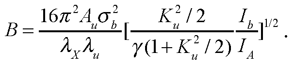
In order to minimize the gain length, one needs a large Pierce parameter pWL and a normalized longitudinal velocity spread Λ sufficiently low compared to 1 that means a sufficiently small energy spread σγ I γ and ε . This expression applies to moderately small beam size ab such that the diffraction parameter B » 1 where B is defined as
A saturation length Lsat required to saturate the am lification can be expressed as

where 7>n and Psat are an input and a saturated power.
The input 7>n and saturated power Psat are related to an electron beam power Pb according to
sat≡1.37AELJPb exp(-0.82A2) ,

where Νλ is the number of electrons per wavelength given by Νλ = lbXx l (ec) .
6.4. Embodiment of a Free-Electron Laser used as an Extreme Ultraviolet source at 13,5 nm wavelength
A fiber laser driven Laser Plasma Accelerator (LP A) based Free-Electron Laser produced Extreme Ultraviolet radiation source at λχ = 13.5 nm wavelength using the undulator with period Xu =5 mm (Case A), 10 mm (Case B) , 15 mm (Case C), 20 mm (Case D) and 25 mm (Case E), all cases of which have the gap-period ratio g l u = 0.2 , e.g. g = 1 mm (Case A), 2 mm (Case B), 3 mm (Case C), 4 mm (Case D) and 5 mm (Case E), respectively. A hybrid undulator comprising NdFeB materials with grade N52 , e.g ., VACODYM® 722HR, and ferromagnetic materials such as tempered Co-Fe alloys (vanadium permendur), e.g., VACOFLUX® 50, provide the peak magnetic field
¾ [T] = 3.694exp(-5.068x 0.2 + 1.520 x 0.22) = 1.425 . The corresponding undulator parameter becomes ^ = 0.i33 [mm] = 0.6655,1.331,1.9965,2.662,3.3275 f°r [mm] = 5, 10,15,20,25 '
The electron beam energy Eb required for producing the Extreme Ultraviolet radiation at the wavelength = 13.5 nm i s g i v e n b y ^ = 192.45^/2(1 + 0.008858/Ιι 2)1/2 , i.e.,
Eb [MeV] = 98.45^/2 (l + 0.008858 2)1/2 . For Case A to E, γ = 475.6> 835.7>ΐ290,1834,2460 and
Eb [MeV] = 243, 427, 659, 937, 1257 '
The Laser Plasma Accelerator (LP A) can provide a high-peak current bunched beam, e.g., IA =50 kA for electron charge Qb = 0.5 nC and bunch duration xb ~ 10 fs. A fiber laser pulse with wavelength = 1/fln after compression is focused on the entrance of gas cell at the normalized laser field a0 = 2 corresponding to the laser intensity / = 5.5 xlO18 WcnT2. Self- guided propagation of such laser pulse in the gas cell requires the group velocity correction factor κ se ,lf, = 1.19 and the matched sp rot radius R m≡k p r m = 3.2. The wakefield reduction factor a due to loaded charge Qb is calculated from a2 + Ca3'2 - 1 = 0 for the electron beam radius k P„ab = 1 , where the coefficients are C = 9 0 6 8 5 5 4 6 4 0 as a = 0.223,0.267,0.302,0.335,0.364 > respectively, for Case A to E.
The important Laser Plasma Accelerator (LP A) parameters are provided as follows: (1) The operating plasma density; «J1017cm"3] = 8.3,5.6,4.2,3.2,2.6
(2) The accelerator length; Iacc[mm] = 18,32,51,74,102
(3) The required pulse duration; TL [fs] = 46, 56, 65, 73, 82
(4) The matched spot radius; rm [/an] = 19,23,27,30,34
(5) The matched power; PL [TW] = 29, 43, 59, 75, 93
(6) The required laser pulse energy; UL [J] = 1.34,2.40,3.79,5.52,7.57
For the Free -Electron Laser operation, the coupling factor Α (ξ) are ,4 = 0.9527,0.8696,0.8083,0.7711,0.7486 with <5 = 0.09065,0.2349,0.3329,0.3899,0.4235 for Case
A to E, respectively. The root mean square (r.m.s) transverse size of the electron bunch is set to ab = 25μια in the undulator and is usually much larger than the normalized transverse emittance εη of the order of 1 m for the Laser Plasma Accelerator (LP A) produced electron beam. For the peak current Ib = 50 kA with the number of electrons per wavelength N = 1.4xl07 and the diffraction parameter £> » 1 , the important Free -Electron Laser parameters are given as follows according to the one-dimensional Free -Electron Laser theory:
(1) The Pierce parameter; ?FEL[%] = 1.117,1.507,1.597, 1.596,1.572
(2) The longitudinal velocity spread; Λ ~ 1 for setting σγ I γ ~ pFEL
(3) The e-folding gain length; Igain [mm] = 41, 61,86,115,146
(4) The saturated power; Psat [GW]≡ 0.6/?^ = 82, 194, 317, 451, 596
(5) The input power; Pm[MW] » 0.94,3.03,5.26,7.48,9.72
(6) The saturation length; L at [mm] = 499, 721, 1016, 1355, 1723
(7) The total number of periods; N = 100,72,68,68,69 .
(8) The spectral bandwidth; ΑΛχ / λΧ[%] : 1/N = 1.0,1.4,1.5,1.5, 1.5
(9) The r.m.s. radiation cone angle;

2 == 116, 97, 82,71,63
(10) The average power at the repetition frequency rep[MHz] ;
Pm [kW] : = (0.82,1.94,3.17, 4.51, 5.96)x rep[MHz] ,
assuming the radiation duration τχ ~ Tb ~ 10 fs.
The repetition rate /rep to be required for generating the average Extreme UltraViolet power of EUV= 1 kW yields fiep [MHz] ~ PEUV I (PsatTx) = 1.22,0.515,0.315,0.223,0.168 . For the production of 1 kW Extreme UltraViolet radiation, the average fiber laser power yields Pi** [MW] = ¾ = 1.63,1.24,1.19,1.22,1.27
Consequently , the minimum average laser power takes place for Case C with the undulator period 15 mm. The average beam power yields ^,av[kW] = QbfiepEb
- 148,110,104,104,105 . The efficiency of the electron beam acceleration is ?7laser→beam[%]
= Pbm IPLm = 9.1, 8.9,8.7,8.5, 8.3 . The efficiency of the production of Extreme UltraViolet radiation yields ¾ser→EUV [%] = 0.061, 0.081, 0.084, 0.082, 0.079
Said Laser Plasma Accelerator (LP A) and Free-Electron Laser parameters for Case A to E producing the Extreme UltraViolet radiation of 1 kW at 13.5 nm wavelength are summarized as shown in Table 1.
Table 1 Examples of the fiber laser driven Laser Plasma Accelerator (LP A) based Free- Electron Laser Extreme UltraViolet light source at 13.5 nm
Case A B C D E
Fiber laser parameters
Laser wavelength [jUm] 1 1 1 1 1
Average laser power [MW] 1.63 1.24 1.19 1.22 1.27
Repetition rate [MHz] 1.22 0.515 0.315 0.223 0.168
Laser energy per pulse [J] 1.34 2.40 3.79 5.52 7.57
Peak power [TW] 29 43 59 75 93
Pulse duration [fs] 46 56 65 73 82
Matched spot radius [jUm] 19 23 27 30 34
LPA parameters
Electron beam energy [MeV] 243 427 659 937 1257
Plasma density [10 cm" ] 8.3 5.6 4.2 3.2 2.6
Accelerator length [mm] 18 32 51 74 102
Charge per bunch [nC] 0.5 0.5 0.5 0.5 0.5
Field reduction factor O 0.223 0.267 0.302 0.325 0.364
Bunch duration [fs] 10 10 10 10 10
Energy spread [%] ~ 1.1 ~ 1.5 ~ 1.6 ~ 1.6 ~ 1.6
Normalized emittance [mm mrad] ~ 1 ~ 1 ~ 1 ~ 1 ~ 1
Transverse beam size [jUm] 25 25 25 25 25
Peak current [kA] 50 50 50 50 50
Average beam power [kW] 148 1 10 104 104 105
Efficiency of laser to beam [%] 9.1 8.9 8.7 8.5 8.3
FEL parameters
Undulator period [mm] 5 10 15 20 25
Radiation wavelength [nm] 13.5 13.5 13.5 13.5 13.5
Gap [mm] 1 2 3 4 5
Peak magnetic field [T] 1.425 1.425 1.425 1.425 1.425
Undulator parameter Ku 0.666 1.33 2.00 2.66 3.33
Pierce parameter [%] 1.117 1.507 1.597 1.596 1.572
Gain length [mm] 41 61 86 115 146
Saturation length [mm] 499 721 1016 1355 1723
Number of periods 100 72 68 68 69
Spectral bandwidth [%] 1.0 1.4 1.5 1.5 1.5 r.m.s. Radiation cone angle ^rad] 116 97 82 71 63
Input power [MW] 0.94 3.03 5.26 7.48 9.72
Saturated power [GW] 82 194 317 451 596
Duration of EUV pulse [fs] 10 10 10 10 10
Average EUV power [kW] 1 1 1 1 1
Efficiency of EUV generation [%] 0.061 0.081 0.084 0.082 0.079
6.4 Embodiment of a Free-Electron Laser used as an Extreme Ultraviolet source at 6,7 nm wavelength
A fiber laser driven Laser Plasma Accelerator (LPA) based Free-Electron Laser produced Extreme Ultraviolet radiation source at λχ =6.7 nm wavelength using the undulator with period Xu =5 mm (Case A), 10 mm (Case B), 15 mm (Case C), 20 mm (Case D) and 25 mm (Case E), all cases of which have the gap-period ratio gl u = 0.2 , e.g. g= 1 mm (Case
A), 2 mm (Case B), 3 mm (Case C), 4 mm (Case D) and 5 mm (Case E), respectively. A hybrid undulator comprising NdFeB materials with grade N52, e.g., VACODYM® 722HR, and ferromagnetic materials such as tempered Co-Fe alloys (vanadium permendur), e.g.,
VACOFLUX® 50, provide the peak magnetic field
¾[T] = 3.694exp(-5.068x 0.2 + 1.520 x 0.22) =1.425 . The corresponding undulator parameter becomes K = 0.133U [mm] = 0.6655,1.331,1.9965,2.662,3.3275 for λ [mm] = 5,10,15,20,25.
The electron beam energy Eb required for producing the Extreme Ultraviolet radiation at the wavelength λχ = 6.7 is given by γ=
 , i.e.,
Eb [MeV] = 98.45/ii;/2(l + 0.008858/l2)1/2. For Case A to E, 7 = 675.1,1186,1830,2604,3492 and Eb [MeV] =345, 606,935,1331,1784..
The Laser Plasma Accelerator (LPA) can provide a high-peak current bunched beam, e.g., IA =50 kA for electron charge Qb = 0.5 nC and bunch duration xb ~ 10 fs. A fiber laser pulse with wavelength =l μτα after compression is focused on the entrance of gas cell at the normalized laser field a0=2 corresponding to the laser intensity / = 5.5xl018 Wcrrf2. Self-guided propagation of such laser pulse in the gas cell requires the group velocity correction factor K„ =1.19 and the matched spot radius R ≡k r =3.2. The wakefield reduction factor due to loaded charge Qb is calculated from 2 + Ca3'2 -1 = 0 for the electron beam
radius kpoh - \ , where the coefficients are C = 7.55,5.70,4.59,3.84,3.32 as a = 0.249,0.295,0.335,0.369,0.400 , respectively, for Case A to E.
The important Laser Plasma Accelerator (LP A) parameters are provided as follows:
(1) The operating plasma density; «J1017cm"3] = 6.5,4.4,3.2,2.5, 2.0
(2) The accelerator length; Zacc [mm] = 26, 47, 74, 109, 150
(3) The required pulse duration; TL [fs] = 52,63,73,83,93
(4) The matched spot radius; rm [/an] = 21,26,30,34,38
(5) The matched power; PL [TW] = 37,55,75,97,120
(6) The required laser pulse energy; UL [J] = 1.92,3.47,5.51,8.06, 11.1
For the FEL operation, the coupling factor Α {ξ are A = 0.9527,0.8696,0.8083,0.7711,0.7486 with ξ = 0.09065,0.2349,0.3329,0.3899, 0.4235 for Case
A to E, respectively. The root mean square (r.m.s) transverse size of the electron bunch is set to ab = 25 mi in the undulator and is usually much larger than the normalized transverse emittance εη of the order of 1 m for the Laser Plasma Accelerator (LP A) produced electron beam. For the peak current Ib = 50 kA with the number of electrons per wavelength
NA = 7xl06 and the diffraction parameter £> » 1 , the important Free-Electron Laser parameters are given as follows according to the one-dimensional Free-Electron Laser theory:
(1) The Pierce parameter; pmL[%] = 0.787, 1.061, 1.125, 1.125, 1.107
(2) The longitudinal velocity spread; Λ ~ 1 for setting σγ I γ ~ pFEL
(3) The e-folding gain length; Igam [mm] = 58.4,86.6, 123,163, 207
(4) The saturated power; Psat [GW]≡ 0.6/?^ = 82, 194, 317, 451, 596
(5) The input power; Pm[MW] » 0.94,3.05,5.3, 7.5,9.8
(6) The saturation length; Lsat [mm] = 709,1024,1441,1923,2445
(7) The total number of periods; N = 142,102,96,96,98.
(8) The spectral bandwidth; ΑΛχ / λΧ[%] : 1/N » 0.71,0.98,1.04,1.04,1.02
(9) The r.m.s. radiation cone angle; ^[ /rad] = 69,57,48,42,37
(10) The average power at the repetition frequency rep[MHz] ;
Pm [kW] : = (0.82,1.94,3.17, 4.51, 5.96)x rep[MHz] ,
assuming the radiation duration τχ ~ Tb ~ 10 fs . The repetition rate /rep to be required for generating the average EUV power of PEUV = 1.5 kW yields rep [MHz] ~ Ευν / (PslitTx) = 1.83,0.773,0.473,0.332,0.252 . For the production of 1.5 kW EUV radiation, the average fiber laser power yields
 = 3.52,2.68,2.60,2.68,2.80
Consequently, the minimum average laser power takes place for Case C with the undulator period 15 mm. The average beam power yields i$,av[kW] = QbfiepEb - 316,234,221,221, 225 . The efficiency of the electron beam acceleration is ?7laser→beam[%] = Pbm IPLm = 8.97,8.73,8.49,8.26,8.03. The efficiency of the production of Extreme UltraViolet radiation yields ¾ser→EUV [%] = 0.043, 0.056, 0.058, 0.056, 0.054 .
= 3.52,2.68,2.60,2.68,2.80
Consequently, the minimum average laser power takes place for Case C with the undulator period 15 mm. The average beam power yields i$,av[kW] = QbfiepEb - 316,234,221,221, 225 . The efficiency of the electron beam acceleration is ?7laser→beam[%] = Pbm IPLm = 8.97,8.73,8.49,8.26,8.03. The efficiency of the production of Extreme UltraViolet radiation yields ¾ser→EUV [%] = 0.043, 0.056, 0.058, 0.056, 0.054 .
Said Laser Plasma Accelerator (LP A) and Free-Electron Laser parameters for Case A to E producing the Extreme UltraViolet radiation of 1 kW at 6.7 nm wavelength are summarized as shown in Table 2.
Table 2 Examples of the fiber laser driven Laser Plasma Accelerator (LP A) based Free- Electron Laser Extreme UltraViolet light source.
Case A B C D E
Fiber laser parameters
Laser wavelength [jUm] 1 1 1 1 1
Average laser power [MW] 3.52 2.68 2.60 2.68 2.80
Repetition rate [MHz] 1.83 0.773 0.473 0.332 0.252
Laser energy per pulse [J] 1.92 3.47 5.51 8.06 11.1
Peak power [TW] 37 55 75 97 120
Pulse duration [fs] 52 63 73 83 93
Matched spot radius [jUm] 21 26 30 34 38
LPA parameters
Electron beam energy [MeV] 345 606 935 1331 1784
Plasma density [1017 cm~3] 6.5 4.4 3.2 2.5 2.0
Accelerator length [mm] 26 47 74 109 150
Charge per bunch [nC] 0.5 0.5 0.5 0.5 0.5
Field reduction factor O 0.249 0.295 0.335 0.369 0.400
Bunch duration [fs] 10 10 10 10 10
Energy spread [%] - 0.8 ~ 1.1 ~ 1.1 ~ 1.1 ~ 1.1
Normalized emittance [mm mrad] ~ 1 ~ 1 ~ 1 ~ 1 ~ 1
Transverse beam size [jUm] 25 25 25 25 25
Peak current [kA] 50 50 50 50 50
Average beam power [kW] 316 234 221 221 225
Efficiency of laser to beam [%] 9.0 8.7 8.5 8.3 8.0
FEL parameters
Radiation wavelength [nm] 6.7 6.7 6.7 6.7 6.7
Undulator period [mm] 5 10 15 20 25
Gap [mm] 1 2 3 4 5
Peak magnetic field [T] 1.425 1.425 1.425 1.425 1.425
Undulator parameter Ku 0.666 1.33 2.00 2.66 3.33
Pierce parameter [%] 0.787 1.06 1.125 1.125 1.107
Gain length [mm] 58.4 86.6 123 163 207
Saturation length [mm] 709 1024 1441 1923 2445
Number of periods 142 102 96 96 98
Spectral bandwidth [%] 0.71 0.98 1.04 1.04 1.02 r.m.s. Radiation cone angle ^rad] 69 57 48 42 37
Input power [MW] 0.94 3.05 5.3 7.5 9.8
Saturated power [GW] 82 194 317 451 596
Duration of EUV pulse [fs] 10 10 10 10 10
Average EUV power [kW] 1.5 1.5 1.5 1.5 1.5
Efficiency of EUV generation [%] 0.043 0.056 0.058 0.056 0.054
6.5 Embodiment of tuning a Free-Electron Laser for the wavelength range from 5 nm to 15 nm
The FEL amplification takes place in the undulator with the undulator period λΜ at the resonant wavelength given by

where γ = Eb I m c2 is the relativistic factor of the electron beam energy E , Ku = 0.9345JT]AK[cm]. Setting the peak magnetic field of the undulator to be 5 = 1.425 T , the corresponding undulator parameter becomes Ku = 0.133 \λ [mm] = 1.9965 for u - 15 mm (CASE C). The electron beam energy Eb required for producing the EUV radiation at the wavelength λχ is given by

The important Laser Plasma Accelerator (LP A) parameters are provided as a function of FEL wavelength λχ :
(1) The operating plasma density; n = 4.2 x l017 [cm-3](^^)1/2
13.5nm
(2) The accelerator length;
13.5nm 3/4
L acc = 51Γ Lηιηι1( )
(3) The required pulse duration;
13.5nm
τ, = 65 [fs](
(4) The matched spot radius;

(5) The required laser peak power;
PL = 59 [TW](±^!^)1/2
(6) The required laser pulse energy;

The important Free-Electron Laser parameters are all given as a function of FEL wavelength
(1) The Pierce parameter;
λ
pFFT = 1.597[%]( ^-)m
j 13.5nm
(2) The longitudinal velocity spread; Λ = 1 for setting σ I γ ~ pFEL
(3) The e-folding gain length;
13.5nm 1/2
L gain = 86 L mm 3 )
X
(4) The saturated power; = 317 [GW]
(5) The input power; Pm « 5.3 [MW]
(6) The saturation length; L sat = 1016 [mm](±^ I 7 /2
Ax
(7) The total number of periods; .
N w = L sat I λ u = 68(^^ 1 -) 71/2
(8) The spectral bandwidth; Αλχ I λχ ~ 1 / N « 1.5[%]
(9) The r.m.s. radiation cone angle;
θ = -L { 1 + K / 2 2 = 82[^rad](— ^— )1M
ms 2γ N 13.5nm
(10) The average power at the repetition frequency rep[MHz] ;
P av ~P sattT XY.f J rep =3.17[ LkW] -'/-'rep
for the radiation duration τ Aν ~T a~ 10 fs.
(11) The repetition rate /rep to be required for generating the average Extreme Ultraviolet power of PW = 1 kW;
/rep^Ew/(¾) = 0-315[MHz]
(12) The average fiber laser power for the production of 1 kW Extreme Ultra Violet radiation;
13.5nm^3/4
^v - ¾ = 119[MW](—— )
x
(13) The average electron beam power;
^=e^ = 104lkW](^≥)U2
(14) The efficiency of the electron beam acceleration;
λ
n 'laser— .beam =P bhw /P Lav =8.7[ L%]( 13 )1
(15) The efficiency of the production of Extreme Ultra Violet radiation;
λ
η ',laser^ wEUnV=Pw EUnV,/P Lrav =0.084[ L%]( ] ^-f4
For undulator period Xu = 15 mm , the average Extreme Ultraviolet power of = 1 kW, the electron beam energy Eb , the operating plasma density ne , the accelerator length Zacc , the required laser peak power PL , the required laser pulse energy UL , the Pierce parameter pmL , the saturation length sat , the average fiber laser power PL and the efficiency of the production of Extreme UltraViolet radiation 77eff are shown as a function of the radiation wavelength λχ for the range from 5 nm to 15 nm in Fig.14, obtained for a given peak magnetic field and a given undulator period, which have been previously set (e.g. Bu=\ .425 T and λ =15 mm.)
Other examples have been given respectively in table 1 and 2 of section 6.4 for other cases A, B, D, E, F related to other examples of ondulator period with Bu = 1.425 T ).
Citation List
Patent Literature
(1) U.S. patent application No. 13/445,195, filed on Apr. 12, 2012, entitled LASER PRODUCED PLASMA EUV LIGHT SOURCE, Pub. No. US 2012/0228526 Al .
(2) U.S. patent No. 4,761,584, Date of patent Aug. 2, 1988, entitled STRONG PERMANENT MAGNET-ASSISTED ELECTROMAGNETIC UNDULATOR.
(3) U.S. patent No. 5,019,863, Date of patent May 28, 1991, entitled WEDGED-POLE
HYBRID UNDULATOR.
(4) International patent application No. PCT/US2012/050135, filed on 09.08.2012, Pub. No. WO/2013/023053, Pub. Date, 14. 02.2013, ENTITLED COMPACT UNDULATOR SYTEM AND METHODS.
Non patent Literature
(1) A. Pak, K. A. Marsh, S. F. Martins, W. Lu, W. B. Mori, and C. Joshi, "Injection and Trapping of Tunnel-Ionized Electrons into Laser-Produced Wakes," Phys. Rev. Lett. 104, 025003 (2010).
(2) C. McGuffey, A. G. R. Thomas, W. Schumaker, T. Matsuoka, V. Chvykov, F. J. Dollar, G. Kalintchenko, V. Yanovsky, A. Maksimchuk, K. Krushelnick, V. Y. Bychenkov, I. V. Glazyrin, and A. V. Karpeev, "Ionization Induced Trapping in a Laser Wakefield Accelerator," Phys. Rev. Lett. 104, 025004 (2010).
(3) C. Xia, J. Liu, W. Wang, H. Lu, W. Cheng, A. Deng, W. Li, H. Zhang, X. Liang, Y. Leng, X. Lu, C. Wang, J. Wang, K. Nakajima, R. Li, and Z. Xu, "Effects of self-focusing on tunnel- ionization-induced injection in a laser wakefield accelerator," Phys. Plasmas 18, 113101 (2011).
(4) J. S. Liu, C. Q. Xia, W. T. Wang, H. Y. Lu, C. Wang, A. H. Deng, W. T. Li, H. Zhang, X. Y. Liang, Y. X. Leng, X. M. Lu, C. Wang, J. Z. Wang, K. Nakajima, R. X. Li, and Z. Z. Xu, "All-Optical Cascaded Laser Wakefield Accelerator Using Ionization-induced Injection," Phys. Rev. Lett. 107, 035001 (2011).
(5) B. B. Pollock, C. E. Clayton, J. E. Ralph, F. Albert, A. Davidson, L. Divol, C. Filip, S. H.
Glenzer, K. Herpoldt, W. Lu, K. A. Marsh, J. Meinecke, W. B. Mori, A. Pak, T. C. Rensink, J.
S. Ross, J. Shaw, G. R. Tynan, C. Joshi, and D. H. Froula, "Demonstration of a Narrow Energy
Spread, similar to 0.5 GeV Electron Beam from a Two-Stage Laser Wakefield Accelerator,"
Phys. Rev. Lett. 107, 045001 (2011).
(6) M. Chen, E. Esarey, C. B. Schroeder, C. G. R. Geddes, and W. P. Leemans, "Theory of ionization-induced trapping in laser-plasma accelerators," Phys. Plasmas 19, 033101 (2012).
(7) Kazuhisa Nakajima, Haiyang Lu, Xueyan Zhao, Baifei Shen, Ruxin Li and Zhizhan Xu,
"100-GeV large scale laser plasma electron acceleration by a multi-PW laser" Chinese Optics
Letters 11 (1), 013501-1-15 (2013).
(8) J. K. Lim, P. Frigola, G. Travish, J. B. Rosenzweig, S. G. Anderson, W. J. Brown, J. S.
Jacob, C. L. Robbins, and A. M. Tremaine, "Adjustable, short focal length permanent-magnet
quadrupole based electron beam final focus system", PHYSICAL REVIEW SPECIAL TOPICS - ACCELERATORS AND BEAMS 8, 072401-1-17 (2005).
(9) P. Elleaume, J. Chavanne, Bart Faatz, "Design Considerations for a 1 angstrom SASE Undulator", Nuclear Instruments and Methods in Physics Research A 455, 503-523 (2000). (10) T. Eichner, F. Griiner, S. Becker, M. Fuchs, D. Habs, R. Weingartner, U. Schramm, H.
Backe, P. Kunz, and W. Lauth, "Miniature magnetic devices for laser-based, table-top free- electron lasers", PHYSICAL REVIEW SPECIAL TOPICS - ACCELERATORS AND BEAMS 10, 082401 (2007).
(11) C. Pagani, E.L. Saldin, E.A. Schneidmiller, M.V. Yurkov, "Design considerations of 10 kW-scale extreme ultraviolet SASE FEL for lithography", Nuclear Instruments and Methods in
Physics Research A 463, 9-25 (2001).
Claims
1. A Free Electron Laser source generating an electromagnetic beam presenting a wavelength, called Free Electron Laser wavelength λχ , belonging to the range from 5nm to
15nm, said Free Electron Laser comprising:
a fiber-based laser (1), comprising a plurality of amplifying fibres (831 , 841 , 851) wherein an initial laser pulse is distributed and amplified, and means for grouping together the elementary pulses amplified in the said fibre in order to form an a single amplified global laser pulse (3), and comprising a stretching device (82) able to stretch out in time said initial laser pulse, according to the chirped pulse amplification technique and a grating pulse compressor (87) able to compress in time the said single amplified global laser pulse, according to the chirped pulse amplification technique, said fiber-laser being tuned using at least one parameter, called fiber-based laser parameter, said at least one fiber-based laser parameter being obtained as a function of said Free Electron Laser wavelength λχ ;
- a laser plasma accelerator (6) wherein, in a bubble regime of said plasma accelerator said global laser pulse (3) generates relativistic electron beams (10),
said laser plasma accelerator being tuned using at least one parameter, called laser plasma accelerator parameter, said at least one laser plasma accelerator parameter being obtained as a function of said Free Electron Laser wavelength λχ ;
- a beam focusing system (12) transporting electron beams (10) from the laser plasma accelerator to an undulator,
said undulator (13) wherein relativistic electron beams (10) generate an electromagnetic beam, a peak magnetic field and a period of said undulator being previously set, said undulator being tuned using at least one parameter, called undulator parameter, said at least one undulator parameter being obtained as a function of said Free Electron Laser wavelength λχ ;
a beam separator system, wherein the said electron beam (10) and the said electromagnetic beam are separated.
2. A Free Electron Laser source according to claim 1 or 2 wherein said laser plasma accelerator (6) comprises:
a first gas cell (21) filled with mixed gas, and
a second gas cell (24) filled with pure helium gas .
a gas feeding system.
3. A Free Electron Laser source according to claim 3 wherein said laser plasma accelerator (6) comprise means for modifying the length of the said second gas cell.
4. A Free Electron Laser source according to any of claim 1 to 4 wherein said beam separator system comprises a dipole magnet (16) for bending electron beams (10) and a beam dump.
5. A Free Electron Laser source according to any of claim 1 to 5 wherein said electromagnetic beam is a Extreme Ultraviolet beam.
6. A Free Electron Laser source according to claim 6 wherein said Extreme UltraViolet beam wavelength is 13.5 nm.
7. A Free Electron Laser source according to claim 6 wherein said Extreme UltraViolet beam wavelength is 6.7 nm.
Priority Applications (1)
| Application Number | Priority Date | Filing Date | Title |
|---|---|---|---|
| US14/917,622 US9768580B2 (en) | 2013-09-09 | 2014-09-09 | Free-electron laser driven by fiber laser-based laser plasma accelerator |
Applications Claiming Priority (2)
| Application Number | Priority Date | Filing Date | Title |
|---|---|---|---|
| EP13306235.6A EP2846422A1 (en) | 2013-09-09 | 2013-09-09 | Free-Electron Laser driven by fibre based laser feeding a Laser Plasma Accelerator |
| EP13306235.6 | 2013-09-09 |
Publications (1)
| Publication Number | Publication Date |
|---|---|
| WO2015032995A1 true WO2015032995A1 (en) | 2015-03-12 |
Family
ID=49641695
Family Applications (1)
| Application Number | Title | Priority Date | Filing Date |
|---|---|---|---|
| PCT/EP2014/069222 Ceased WO2015032995A1 (en) | 2013-09-09 | 2014-09-09 | Free-electron laser driven by a fibre-based laser feeding a laser plasma accelerator |
Country Status (3)
| Country | Link |
|---|---|
| US (1) | US9768580B2 (en) |
| EP (1) | EP2846422A1 (en) |
| WO (1) | WO2015032995A1 (en) |
Cited By (1)
| Publication number | Priority date | Publication date | Assignee | Title |
|---|---|---|---|---|
| RU184178U1 (en) * | 2018-03-12 | 2018-10-18 | Дмитрий Николаевич Харитонов | SUPERCONDUCTOR EMISSION ONDULATOR |
Families Citing this family (16)
| Publication number | Priority date | Publication date | Assignee | Title |
|---|---|---|---|---|
| HUE047712T2 (en) * | 2014-10-13 | 2020-05-28 | Tae Tech Inc | An assembly for joining and compressing dense toroids |
| FR3028093B1 (en) * | 2014-11-05 | 2019-05-31 | Ecole Polytechnique | LASER-PLASMA LENS |
| US9844124B2 (en) * | 2015-03-12 | 2017-12-12 | Globalfoundries Inc. | Method, apparatus and system for using free-electron laser compatible EUV beam for semiconductor wafer metrology |
| CN105555008A (en) * | 2015-12-03 | 2016-05-04 | 中国工程物理研究院激光聚变研究中心 | Positive electron beam transmission system |
| GB201617173D0 (en) * | 2016-10-10 | 2016-11-23 | Univ Strathclyde | Plasma accelerator |
| KR102031796B1 (en) * | 2016-12-28 | 2019-10-15 | 기초과학연구원 | Length variable gas target and laser-gas reaction system comprising the same |
| CN106873022A (en) * | 2017-03-20 | 2017-06-20 | 中国科学院上海光学精密机械研究所 | A kind of high-resolution electron spectrometer accelerated suitable for laser tail electronics |
| WO2018198227A1 (en) * | 2017-04-26 | 2018-11-01 | ギガフォトン株式会社 | Euv light generation device |
| US11037765B2 (en) * | 2018-07-03 | 2021-06-15 | Tokyo Electron Limited | Resonant structure for electron cyclotron resonant (ECR) plasma ionization |
| KR102828442B1 (en) * | 2018-11-02 | 2025-07-01 | 테크니쉐 유니버시테이트 아인트호벤 | Tunable source of intense, narrowband, fully coherent soft X-rays |
| JP2022525912A (en) * | 2019-03-18 | 2022-05-20 | ザ リージェンツ オブ ザ ユニバーシティ オブ カリフォルニア | Compact Laser Wake Field Accelerated Systems and Methods for Electrons and X-rays |
| EP3749065B1 (en) * | 2019-03-27 | 2022-08-17 | Huazhong University of Science and Technology | Electron radiation system |
| CN113300198B (en) * | 2021-05-14 | 2023-12-01 | 江苏师范大学 | Single-frequency narrow linewidth distributed feedback pulse fiber laser and its implementation method |
| WO2025184366A1 (en) * | 2024-02-27 | 2025-09-04 | Loma Linda University Health | Systems and methods to create electron minibeams |
| CN118033992B (en) * | 2024-04-11 | 2024-06-25 | 深圳大学 | Extreme ultraviolet light source |
| CN120470805B (en) * | 2025-07-08 | 2025-10-03 | 中国科学院长春光学精密机械与物理研究所 | A design method for temperature gradient compensation electrode of CO2 laser amplifier |
Family Cites Families (4)
| Publication number | Priority date | Publication date | Assignee | Title |
|---|---|---|---|---|
| US4761584A (en) | 1987-01-30 | 1988-08-02 | The United States Of America As Represented By The United States Department Of Energy | Strong permanent magnet-assisted electromagnetic undulator |
| US5019863A (en) | 1987-09-30 | 1991-05-28 | Amoco Corporation | Wedged-pole hybrid undulator |
| US8530871B2 (en) | 2007-07-13 | 2013-09-10 | Cymer, Llc | Laser produced plasma EUV light source |
| WO2013023053A1 (en) | 2011-08-09 | 2013-02-14 | Cornell University | Compact undulator system and methods |
-
2013
- 2013-09-09 EP EP13306235.6A patent/EP2846422A1/en not_active Withdrawn
-
2014
- 2014-09-09 US US14/917,622 patent/US9768580B2/en not_active Expired - Fee Related
- 2014-09-09 WO PCT/EP2014/069222 patent/WO2015032995A1/en not_active Ceased
Non-Patent Citations (13)
| Title |
|---|
| A. PAK ET AL: "Injection and Trapping of Tunnel-Ionized Electrons into Laser-Produced Wakes", PHYSICAL REVIEW LETTERS, vol. 104, no. 2, 1 January 2010 (2010-01-01), XP055101496, ISSN: 0031-9007, DOI: 10.1103/PhysRevLett.104.025003 * |
| C. MCGUFFEY ET AL: "Ionization Induced Trapping in a Laser Wakefield Accelerator", PHYSICAL REVIEW LETTERS, vol. 104, no. 2, 1 January 2010 (2010-01-01), XP055101503, ISSN: 0031-9007, DOI: 10.1103/PhysRevLett.104.025004 * |
| G. MOUROU ET AL: "ICAN and 100GeV's Ascent", EURONNAC, MAY 2012 MEETING, CERN, 1 May 2012 (2012-05-01), pages 1 - 60, XP055101548, Retrieved from the Internet <URL:http://indico.cern.ch/event/187383/session/3/contribution/7/material/slides/0.pdf> [retrieved on 20140211] * |
| GÉRARD MOUROU: "Workshop IZEST 100GeV Ascent", May 2013 (2013-05-01), pages 1 - 18, XP055101549, Retrieved from the Internet <URL:https://gargantua.polytechnique.fr/siatel-web/linkto/mICYYYS74tY> [retrieved on 20140211] * |
| H.-P. SCHLENVOIGT ET AL: "A compact synchrotron radiation source driven by a laser-plasma wakefield accelerator", NATURE PHYSICS, vol. 4, no. 2, 9 December 2007 (2007-12-09), pages 130 - 133, XP055101295, ISSN: 1745-2473, DOI: 10.1038/nphys811 * |
| HAFZ NASR: "Laser-driven electron acceleration research at APRI and future application to compact light sources", JOURNAL OF THE KOREAN PHYSICAL SOCIETY, vol. 56, no. 11, 15 January 2010 (2010-01-15), pages 241, XP055101292, ISSN: 0374-4884, DOI: 10.3938/jkps.56.241 * |
| H-P SCHLENVOIGT ET AL: "Synchrotron Radiation From Laser-Accelerated Monoenergetic Electrons", IEEE TRANSACTIONS ON PLASMA SCIENCE, IEEE SERVICE CENTER, PISCATAWAY, NJ, US, vol. 36, no. 4, 1 August 2008 (2008-08-01), pages 1773 - 1781, XP011232933, ISSN: 0093-3813, DOI: 10.1109/TPS.2008.927146 * |
| P. GASIOR: "Can ICAN can CERN into a can?: review study", PROCEEDINGS OF SPIE, vol. 8903, 25 October 2013 (2013-10-25), pages 89030N, XP055101289, ISSN: 0277-786X, DOI: 10.1117/12.2035369 * |
| PUKHOV A ET AL: "The bubble regime of laser-plasma acceleration: monoenergetic electrons and the scalability; The bubble regime of laser-plasma acceleration", PLASMA PHYSICS AND CONTROLLED FUSION, IOP, BRISTOL, GB, vol. 46, no. 12B, 1 December 2004 (2004-12-01), pages B179 - B186, XP020049654, ISSN: 0741-3335, DOI: 10.1088/0741-3335/46/12B/016 * |
| TOSHIKI TAJIMA ET AL: "ICAN: The Next Laser Powerhouse", OPTICS AND PHOTONICS NEWS, 1 May 2013 (2013-05-01), pages 36 - 43, XP055101291, DOI: http://dx.doi.org/10.1364/OPN.24.5.000036 * |
| VIEIRA J F ET AL: "Three-Dimensional Structure of the Laser Wakefield Accelerator in the Blowout Regime", IEEE TRANSACTIONS ON PLASMA SCIENCE, IEEE SERVICE CENTER, PISCATAWAY, NJ, US, vol. 36, no. 4, 1 August 2008 (2008-08-01), pages 1124 - 1125, XP011232963, ISSN: 0093-3813, DOI: 10.1109/TPS.2008.922930 * |
| WIGGINS S M ET AL: "High quality electron beams from a laser wakefield accelerator", CONFERENCE ON LASERS AND ELECTRO-OPTICS (CLEO) AND QUANTUM ELECTRONICS AND LASER SCIENCE CONFERENCE (QELS), 2010 : 16 - 21 MAY 2010, SAN JOSE, CA, USA, IEEE, PISCATAWAY, NJ , USA, 16 May 2010 (2010-05-16), pages 1 - 2, XP031701440, ISBN: 978-1-55752-890-2 * |
| YOSHITAMA H ET AL: "PHYSICS OF GASES, PLASMAS, AND ELECTRIC DISCHARGES; Self-Injection and Acceleration of Monoenergetic Electron Beams from Laser Wakefield Accelerators in a Highly Relativistic Regime", CHINESE PHYSICS LETTERS, INSTITUTE OF PHYSICS PUBLISHING, BRISTOL, GB, vol. 25, no. 8, 1 August 2008 (2008-08-01), pages 2938 - 2941, XP020141951, ISSN: 0256-307X, DOI: 10.1088/0256-307X/25/8/056 * |
Cited By (1)
| Publication number | Priority date | Publication date | Assignee | Title |
|---|---|---|---|---|
| RU184178U1 (en) * | 2018-03-12 | 2018-10-18 | Дмитрий Николаевич Харитонов | SUPERCONDUCTOR EMISSION ONDULATOR |
Also Published As
| Publication number | Publication date |
|---|---|
| US9768580B2 (en) | 2017-09-19 |
| EP2846422A1 (en) | 2015-03-11 |
| US20160226212A1 (en) | 2016-08-04 |
Similar Documents
| Publication | Publication Date | Title |
|---|---|---|
| US9768580B2 (en) | Free-electron laser driven by fiber laser-based laser plasma accelerator | |
| Ferri et al. | High-brilliance betatron γ-ray source powered by laser-accelerated electrons | |
| KR102340172B1 (en) | Free electron laser radiation source for the euv | |
| CN103745760B (en) | Gamma ray projector based on full ray laser plasma accelerator | |
| US11831122B2 (en) | Free electron laser orbital debris removal system | |
| Socol et al. | Compact 13.5-nm free-electron laser for extreme ultraviolet lithography | |
| CN108701502A (en) | Production of radioisotopes | |
| Nakajima | Laser-driven electron beam and radiation sources for basic, medical and industrial sciences | |
| Labat et al. | Robustness of a plasma acceleration based free electron laser | |
| Nakajima | Conceptual designs of a laser plasma accelerator-based EUV-FEL and an all-optical Gamma-beam source | |
| WO2017153104A1 (en) | Electron source for a free electron laser | |
| Stupakov et al. | FEL oscillator for EUV lithography | |
| Freund et al. | Nonlinear harmonic generation in free-electron lasers with helical wigglers | |
| Schreiber | Soft and hard x-ray sase free electron lasers | |
| Albert et al. | Betatron x-ray production in mixed gases | |
| Khan et al. | Accelerator-Based Photon Sources | |
| Pogorelsky | Terawatt picosecond CO 2 laser technology for strong field physics applications | |
| Rossbach | X-ray free electron lasers based on high brilliance linacs | |
| Socol et al. | 13.5 nm free-electron laser for EUV lithography | |
| Leach | The free electron laser, offspring of synchrotron radiation | |
| Azima et al. | EXPERIMENTAL LAYOUT OF 30 nm HIGH | |
| Rossbach | The TESLA Free Electron Laser-Concept and Status | |
| Schneider | Scientific highlights from operation of FLASH and new opportunities with LCLS | |
| Cha et al. | Design Considerations of Magnetic Devices for Bright Laser-plasma Undulator Radiation in the Water Window Spectral Range | |
| Nakajima et al. | GeV laser acceleration research at JAERI-APR |
Legal Events
| Date | Code | Title | Description |
|---|---|---|---|
| 121 | Ep: the epo has been informed by wipo that ep was designated in this application |
Ref document number: 14765913 Country of ref document: EP Kind code of ref document: A1 |
|
| NENP | Non-entry into the national phase |
Ref country code: DE |
|
| WWE | Wipo information: entry into national phase |
Ref document number: 14917622 Country of ref document: US |
|
| 122 | Ep: pct application non-entry in european phase |
Ref document number: 14765913 Country of ref document: EP Kind code of ref document: A1 |