1. Field of the invention
-
The invention relates to a new embodiment of a Free-Electron Laser ("FEL").
-
The invention also relates to the use of such a Free-Electron Laser as an Extreme UltraViolet ("EUV") light sources for Extreme UltraViolet lithography.
2. Background of the invention
Background of Free-Electron Lasers ("FEL")
-
A Free-Electron laser (FEL), is a type of laser that use a relativistic electron beam that moves freely through a magnetic structure, in order to create a beam consisting of coherent electromagnetic radiation that can reach high power. In this type of laser, the free electron beam is the lasing medium. The free-electron laser has the widest frequency range of any laser type, and can be widely tunable, currently ranging in wavelength from microwaves, through terahertz radiation and infrared, to the visible spectrum, ultraviolet, and X-ray.
-
To create a Free-Electron Laser, a beam of electrons is accelerated to almost the speed of light. The beam passes through the Free-Electron Laser oscillator, a periodic transverse magnetic field produced by an arrangement of magnets with alternating poles within an optical cavity along the beam path. This array of magnets is commonly configured as an undulator, because it forces the electrons in the beam to follow a sinusoidal path. The acceleration of the electrons along this path results in the release of photons (synchrotron radiation). Since the electron motion is in phase with the field of the light already emitted, the fields add together coherently. The wavelength of the light emitted can be readily tuned by adjusting the energy of the electron beam or the magnetic field strength of the undulators.
-
A free-electron laser requires the use of an electron accelerator, which is very voluminous, requires a high voltage supply, has a very low repetition rate and is expensive.
Background of Extreme Ultraviolet ('EUV") light sources
-
Extreme UltraViolet ("EUV") with wavelengths below about 50 nm and more specifically around and below 13.5 nm can be used in micro lithography processes to enhance the resolution of optical systems that are limited by the diffraction limit of light accompanying miniaturization of semiconductor integrated circuits. This technology called as extreme ultraviolet lithography (EUVL) is capable of providing resolution below 30 nm that had been impossible with conventional optical lithography that utilizes deep ultraviolet (DUV) light sources with wavelengths of 248 nm or 193 nm.
-
The current technologies for generating high power Extreme UltraViolet radiation at 13.5 nm, referred to as laser produced plasma (LPP), employs the deposition of laser energy into a source element, such as xenon (Xe), tin (Sn) or lithium (Li), creating ionized gas microplasma at electron temperatures of several tens of electron volts. As these highly excited ions decay, energetic radiation is emitted in all directions of 4π radians.
-
One particular laser produced plasma (LPP) technique involves irradiating molten tin droplets with one or more pre-pulse(s) followed by a main pulse. In this regard, CO2 lasers at the wavelength of 10.6 µm provide certain advantages as a drive laser producing main pulses in the laser produced plasma (LPP) process thanks to the ability to produce a relatively high conversion efficiency, i.e., the ratio of output Extreme UltraViolet in-band to drive laser input power.
-
For Extreme UltraViolet lithography, the 13.5 nm radiation is collected by a mirror (either grazing incidence or normal incidence) and focused to an intermediate focal point where it is relayed to the scanner optics and, ultimately, the wafer.
-
For example, one apparatus currently being developed with the goal of producing about 100 W at the intermediate location contemplates the use of a pulsed, focused 10 - 12 kW CO2 drive laser which is synchronized with a droplet generator to sequentially irradiate about 40 k - 100 k tin droplets per second. For this purpose, there is a need to produce a stable stream of droplets at a relatively high repetition rate (e.g. 40 - 100 kHz or more) and deliver the droplets to an irradiation site with high accuracy and good repeatability in terms of timing and position, i.e., with very small jitter, over a relatively long period of time.
-
The current laser produced plasma (LPP) radiation sources have a serious obstacle on the way to a high volume manufacturing (HVM) source such as small efficiency of the radiation source, a limited set of discrete wavelengths and the mitigation of the plasma debris required for the protection of Extreme UltraViolet optics.
Background of Free Electron Laser used as Extreme UltraViolet light sources
-
Free-Electron Laser based radiation sources have evident advantages in wavelength tunability, high efficiency and high output power, compared to current laser produced plasma (LPP) radiation sources. The problem of debris mitigation does not exist at all. There is no need to use a multilayer coated reflective collector, of which reflectivity is limited to about 70%, since the radiation is produced in the diffraction limited volume. Hence, there is no problem with the transport of radiation to the exposure system. Harnessing such advantages of Free-Electron Laser based Extreme UltraViolet radiation sources liberated from the debris mitigation and a mechanical targeting system such as a droplet generator, the Free-Electron Laser based Extreme UltraViolet radiation source may have an average output power of 0.5 kW at a repetition rate of at least 250 kHz for meeting the requirements of the light source at 13.5 nm for the next generation lithography.
-
A proposed Free-Electron Laser based Free-Electron Laser producing a kW-level average output power of Extreme UltraViolet radiation utilizes high-energy electron beams of the order of 1 GeV generated from a radio-frequency (RF)-based linear accelerator that comprises a high-brightness electron injector typically composed of a photocathode RF gun or thermionic high-voltage DC gun and several buncher cavities for producing electron bunches, a several-stage magnetic bunch compressor system comprising a sequence of RF structure and bending magnets for compressing a bunch length and increasing a peak beam current and a main linac composed of a series of room-temperature or superconducting RF cavities with the accelerating gradient of the order of 10 MV/m and a beam transport system including beam focusing and defocusing electro-quadrupole magnets, lastly followed by undulators with a total length of 30 m, providing alternating magnetic fields to force electrons on a sinusoidal trajectory so that all electrons in a electron bunch emit coherently due to the microbunching process, called as self-amplified spontaneous emission (SASE) Free-Electron Laser. The overall size of a RF linac-driven Free-Electron Laser-based Extreme UltraViolet light source may require a 250 m long facility for a linac-based light source or a 120 m long, 60 m wide area for a recirculator-based light source. The costs for construction and operation of such facility may turn out incredibly so large as to prevent the Free-Electron Laser-based Extreme UltraViolet light sources from industrial realization of the next generation lithography technology.
3. Objective of the invention
-
The objective of the present invention is to overcome the cited disadvantages of the prior art.
-
More specifically, an objective of the invention is to provide a new embodiment of Free Electron Laser, more compact and efficient, cheaper and having a higher repetition rate and a higher average power as the prior art Free Electron Lasers.
-
Another objective of the invention is to provide an efficient Free-Electron Laser-based Extreme UltraViolet light source, usable for industrial lithography technology.
4. Summary of the invention
-
In order to attain these objectives the present invention provides a Free Electron Laser source comprising:
- a fiber-based laser, comprising a plurality of amplifying fibres wherein an initial laser pulse is distributed and amplified, and means for grouping together the elementary pulses amplified in the said fibre in order to form an a single amplified global laser pulse;
- a laser plasma accelerator wherein the said global laser pulse generates relativistic electron beams,
- a beam focusing system transporting electron beams from the laser plasma accelerator,
- an undulator wherein relativistic electron beams generate an electromagnetic beams,
- a beam separator system, wherein the said electron beam and the said electromagnetic beam are separated.
-
The Free Electron Laser source, or Free Electron Laser, according to the invention is more compact and efficient, cheaper and having a higher repetition rate and a higher average power as the prior art Free Electron Laser sources. Preferably, said fiber-based laser comprises:
- a stretching device able to stretch out in time said initial laser pulse, according to the chirped pulse amplification technique,
- a grating pulse compressor able to compress in time the said single amplified global laser pulse, according to the chirped pulse amplification technique.
-
Using this chirped pulse amplification technique (CPA), the fiber-based laser can emit pulses of very high energy.
-
Preferably, said laser plasma accelerator comprises:
- a first gas cell filled with mixed gas, and
- a second gas cell filled with pure helium gas.
- a gas feeding system.
-
Such a laser plasma accelerator is very efficient, with a very high repetition rate.
-
Preferably, said laser plasma accelerator comprise means for modifying the length of the said second gas cell.
-
The wavelength of the electromagnetic beam emitted by the Free Electron Laser source can then be tuned.
-
Preferably said beam separator system comprises a dipole magnet for bending electron beams and a beam dump.
-
Advantageously, said electromagnetic beam is a Extreme UltraViolet beam.
-
The Free Electron Laser according to this embodiment can provide a Extreme UltraViolet source usable for lithography application. Such a Extreme UltraViolet source is more compact and efficient, cheaper and having a higher repetition rate and a higher average power as the prior art Extreme UltraViolet sources.
-
According to a preferred embodiment, said Extreme UltraViolet beam wavelength is 13.5 nm.
-
According to an other possible embodiment, said Extreme UltraViolet beam wavelength is 6.7 nm.
5. Brief description of the drawings
-
The invention will become more fully understood from the following description of preferred but non-limiting embodiments thereof, described in connection with accompanying drawings, wherein:
- Fig.1 shows a schematic diagram of a Free Electron Laser according to an embodiment of the invention, usable as an Extreme UltraViolet light source.
- Fig. 2 illustrates a schematic diagram of a coherent combining fiber-based drive laser used in the Free Electron Laser of Fig. 1.
- Fig. 3 shows the two-stage gas cell plasma accelerator of the Free Electron Laser of Fig. 1.
- Fig. 4 shows the laser plasma electron accelerator system of the Free Electron Laser of Fig. 1, comprising the gas cell plasma accelerator of Fig. 3.
- Fig. 5 illustrates schematically electron acceleration mechanism due to laser wakefield.
- Fig. 6 shows a schematic view of a miniature permanent magnet quadrupole (PMQ).
- Fig. 7 shows an example of a beam focusing system comprising four permanent magnet quadrupoles (PMQ) of the type represented by Fig 6.
- Fig. 8 shows schematically a planar undulator made of pure permanent magnets producing a vertical field.
- Fig. 9 shows schematically a hybrid planar undulator made of permanent magnets and ferromagnetic material, e.g., iron or cobalt steel.
- Fig. 10A and 10B show a schematic assembly of the undulator used in the Free Electron Laser of Fig. 1.
- Fig. 11A, 11B and 11C shows a monolithic beam dump system comprising a permanent magnet dipole separating electron beams from Extreme UltraViolet radiation and a electron beam dump.
- Fig. 12 illustrates a setup of a compact self-amplified spontaneous emission (SASE) Free-Electron Laser system comprising the beam focusing system of Fig. 4B, the compact undulator of Fig. 5C and the beam dump system of Fig. 6A.
- Fig. 13 illustrates schematically the Extreme UltraViolet light source of Fig. 1, based on a compact Free-Electron Laser driven by a fiber laser-based plasma accelerator according to aspects of an embodiment of the present invention.
6. Detailed description of the preferred embodiments of the invention
6.1 General description of a Free-Electron Laser according to an embodiment of the invention
-
With initial reference to Fig. 1, there is shown a schematic diagram of a proposed Free-Electron Laser according to one aspect of an embodiment. As shown in Fig. 1, and described in further detailed below, the proposed Free-Electron Laser may include a drive laser system 1 for generating high energy laser pulses at a high repetition rate of the order of 1 MHz and delivering intense laser pulses 3 compressed through a pulse compressor chamber 2 into a laser plasma accelerator chamber 4. Such a laser-driven Free-Electron Laser can be used as an Extreme UltraViolet light source.
Fibre-type laser
-
Figure 2 shows an item of drive laser system 1 for producing high-energy laser pulses.
-
In this drive laser system 1, a low-energy laser pulse 810 is produced by an oscillator 81. This pulse 810 is then stretched out in time, according to the chirped pulse amplification (CPA) technique, by a stretching device 82, comprising a pair of diffraction gratings 821 and 822, having the effect of offsetting in time the various spectral components of the original low-energy pulse 810. The stretched pulse 820 then has a lower peak power and a longer duration of the pulse 810.
-
This laser pulse 820 is then distributed in a plurality of amplifying fibres 831 forming a first amplifying stage 83 of the fibre-type laser amplifier. The various fibres are separated from one another so as to make it possible to cool them effectively. Each of the amplifying fibres 831 comprises a core made from doped material, and is optically pumped, so as to optically amplify the laser pulse flowing in the fibre. The pulse passing through each of these amplifying fibres 831 is then amplified, and is then itself distributed in a plurality of amplifying fibres 841 forming the second amplification stage 84 of the fibre-type laser amplifier. Once again, the pulse passing through each of these amplifying fibres 841 is amplified and is then itself distributed in a plurality of amplifying fibres 851 forming the third amplification stage 85 of the fibre-type laser amplifier. Thus, in each amplification stage, the pulse is amplified in a plurality of fibres independent of one another and then divided so that pulses of lower power are transmitted to each of the higher-level amplification fibres.
-
The third and last amplification stage 85 then comprises a very large number of amplifying fibres, for example around 106. Each of the amplifying fibres of this third stage is extended by a transmission fibre having a very low loss level. The transmission fibres are collected together in a cluster 86 so that the pulses emerging from each of the ends of these transmission fibres are emitted in parallel and juxtaposed. These pulses then form a single amplified global pulse 860.
-
This amplified global pulse 860 is compressed timewise by a compressor 87, located in the pulse compressor chamber 2. This compressor 87 comprises a pair of diffraction gratings 871 and 872, grouping together in time the various spectral components of the pulse. The pulse 3 emerging from this temporal compressor 17 then has a very high energy and very short duration.
-
Two stages gas cell plasma accelerator with ionization-induced injection
-
As shown in Fig. 1, the ultrashort intense laser pulse 3 is focused by an off-axis parabolic mirror 5 on the entrance of a two-stage gas cell 6, of which the first cell referred to an injector is filled with a mixed gas, e.g., helium gas mixed with nitrogen, and the second cell referred to as an accelerator is filled with a pure gas, e.g., hydrogen or helium. The gases are fed through a gas flow control system 7 to the two-stage gas cell separately at the different pressures.
-
As described below, in the injector of the gas cell 6, the said laser pulse 3 excites large-amplitude plasma wakefields, of which an accelerating electric field can trap plasma electrons exclusively out of the inner shell electrons and accelerate them owing to ionization-induced injection. A pre-accelerated electron beam 10 from the injector is further accelerated to the relativistic energy of the order of 1 GeV in the accelerator stage of the gas cell 6, where the laser pulse generates plasma wakefields of the order of 1 GV/cm. A transmitted laser light is directed through a mirror with a beam hole 8 to a recovery box 9 that includes diagnostics and absorbers of the transmitted laser pulses.
-
This plasma accelerator is particularly advantageous when it is combined with a fiber-based laser, a beam focusing system, an undulator and a beam separator system according to the invention. However, such a laser plasma accelerator comprising a first gas cell filled with mixed gas, and a second gas cell filled with pure helium gas can also be combined with an other type of laser, for producing relativistic electron beams.
Beam focusing system, undulator and separation chamber
-
The output electron beam 10 from the laser plasma accelerator chamber 4 is transported into an undulator 13 through a beam focusing system 12, installed in a radiation chamber 11. As described below, the electron beam 10 focused by quadrupole magnetic field of the beam focusing system 12 generates the resonantly amplified Extreme UltraViolet radiation 14 due to self-amplified spontaneous emission (SASE) mechanism when passing through the alternating dipole magnetic fields of the undulator 13 that force the electron bunch on a sinusoidal trajectory.
-
After passing through the undulator 13, the electron bunch is decelerated so strongly that it becomes non-resonant and could not contribute to the amplification of the Extreme UltraViolet radiation, i.e., the onset of saturation. The decelerated electron beam 10 is separated from the Extreme UltraViolet radiation 14 in the dipole magnetic field of the deflection magnet 16 and dumped to a beam dump 17, while the saturated Extreme UltraViolet radiation 14 is extracted from a beam separation chamber 15 and directed to a Extreme UltraViolet lithography scanner/stepper.
6.2. Detailed description of the laser plasma accelerator chamber
Two-stage gas cell
-
Fig. 3 shows schematically a two-stage gas cell 6 comprising an injector stage 21 and an accelerator stage 24 for efficient electron trapping and acceleration in laser wakefields. As shown in Fig. 4, the two-stage gas cell is set up in a laser plasma accelerator chamber 4 and a compressed laser pulse 3 from the pulse compressor chamber 2 is focused on the entrance of the injector gas cell by an off-axis parabolic mirror 5 with a F-number, e.g., 20.
-
The injector cell 21 is filled with a mixed gas, e.g., 98% He and 2% N2, fed through a gas feedthrough 20 from the gas flow control system 7. The accelerator cell 24 is filled with a pure gas, e.g. H2 or He, fed through a gas feedthrough 24 from the gas flow control system 7. A length of the accelerator stage is variably adjusted with a bellows structure 25 driven by a motorized actuator 26. The laser plasma accelerator chamber 4 is pump out by a vacuum pump system 27 to keep an inside pressure of 10-3 -10-4 Pa.
Description of the physical process
-
Fig. 5 illustrates schematically a physical process 100 for the wakefield excitation and electron trapping and acceleration in wakefields, which are generated when an intense laser pulse propagates a neutral mixed gas in the injector 21. In Fig. 5, the evolution of plasma electron density is shown in the upper plot 101 and the excited longitudinal wakefield is shown in the lower plot 102.
-
As shown in the central part 100 of Fig.5, He and the outer shell electrons up to N5+ are fully ionized in the leading front of the laser pulse with intensity 1.5 × 10¹⁶ W/cm2 to produce plasma electrons in the outer region of the laser pulse, of which the boundary is indicated by a thin dotted line 103. Since two inner shell (K-shell) electrons of N6+ and N7+ are ionized at the laser intensity higher than 1×10¹⁹ W/cm2, the inner shell electrons are produced only near the peak intensity of the laser pulse 3, of which the intensity profile is indicated by a thick dotted line 108 for the normalized laser field a 0 ; 0.855×10⁻⁹ I 1/2[W/cm2]λL [µm] = 2 where I[W/cm2] is the intensity and λL [µm] is the laser wavelength. In the upper plot 101, a thick solid curve 109 indicates the evolution of ionization level of nitrogen (the electron number of ionized nitrogen atom) along the propagation axis. A boundary of the plasma region containing the inner shell electrons from ionized N6+ and N7+ is indicated by a thin dashed line 104.
-
Plasma electrons contained in the boundary 103 are blown out by radiation pressure (ponderomotive force) of the laser pulse 3 with the relativistic intensity a 0 ? 1 and form a narrow dense electron sheath surrounding a spherical ion column behind the laser pulse, often referred to as a bubble 105. Such charge separation generates a strong longitudinal electric field 110 of the order of 100 GV/m at a plasma electron density of 1018 cm-3, which is three orders of magnitude higher than an accelerating field of conventional RF accelerators. In the bubble 105, an electron undergoes a strong focusing force simultaneously. Hence, once electrons 10 are trapped into a bubble, they are efficiently accelerated up to high energy of the order of 1 GeV over a dephasing length of the order of 1 cm, where accelerated electrons outrun a proper accelerating phase.
-
The said inner shell electrons from ionized N
6+ and N
7+ are located near the bubble center on the propagation axis, where the wake potential is a maximum and the expelling ponderomotive force of the laser pulse is a minimum. Contrary to pre-ionized free electrons, whose trajectories move along a narrow sheath outside the bubble, the ionized electrons emitted from the inner shell move close to the bubble axis toward the back of the bubble where the wake potential is a minimum, and eventually trapped into the wakefield in condition that electrons gain a sufficient kinetic energy required for trapping, as shown in the
electron trajectory 106, while the electron shown in the
trajectory 107, ionized earlier and off-axis, slips over the potential well and is not trapped. This mechanism called as ionization-induced injection occurs at the intensity as low as the optical field ionization threshold for the inner shell electrons of impurity gas and significantly increases the trapped charge. As trapping occurs close to the bubble axis, amplitudes of the betatron oscillation after trapping decrease compared to the self-injection from the electron sheath. According to theoretical considerations on the ionization-induced injection, for trapping electrons ionized at the peak of the laser electric field, the minimum laser intensity is given by
where
γp is the Lorentz factor defined as
and
βp is the phase velocity of the plasma wave. For electrons to be trapped at or in front of the laser envelope, the intensity must be
a 0 ≥1.7 for
γp =33. The 1D PIC simulations show that the maximum number of trapped electrons is saturated to be approximately
N emax ∼ 5×10
6 µm
-2 at the mixed gas length
L mix ≈ 1000
λ 0 for the plasma density
ne = 0.001
nc (1.7 × 10
18 cm
-3) with the nitrogen concentration of
α N =1%, and the laser parameters
a 0 = 2 and
cτ 0 ≈ 15
λ 0 due to the beam loading effects and initially trapped particle loss from the separatrix in the phase space, where
λ 0 is the laser wavelength and
nc is the critical plasma density defined as
1.115×10
21[cm
-3]/(
λL [
µm])
2. The number of trapped electrons scales as
Ne [
µm
-2]: 8×10
7 α N kpL mix(
ne /
nc) 1/2 for
α N kpL mix≤2. The energy spread is also proportional to both the mixed gas length and the nitrogen concentration. According to the 2D-PIC simulation for
a 0 = 2, the energy spread of a trapped electron beam may scale as
δE/
E= 0.02[%](
L mix/
λL )(
ne /10
17cm
-3)
-1/2, while the transverse normalized emittance is estimated to be
-
In the bubble (blowout) regime for
a 0≥2 , since an electron-evacuated cavity shape is determined by balancing the Lorentz force of the ion sphere exerted on the electron sheath with the ponderomotive force of the laser pulse, the bubble radius
RB is approximately given as
where
kp =(4
πrene )
1/2 is the plasma wavenumber evaluated with the unperturbed on-axis density
ne , and the classical electron radius
re =
e2 /
mec 2=2.818×10
-13 cm with electron charge
e , mass
me and vacuum light velocity
c. The accelerating field
Ez is given by
E z/
E 0=(1/2)
αkpRB, where
E 0=
mcωp /
e≈96[GV/m](
ne /10
18[cm
-3])
1/2 and
α represents a factor taking into account the beam loading and the difference between the simulation and theoretical estimation. The maximum energy gain limited due to dephasing is given by Δ
γ max =
W max/
mec 2≈(2/3)
ακ self a 0(
nc /
ne ), where
is a correction factor of the group velocity for a self-guided relativistic laser pulse, of which the relativistic factor related to the group velocity
βg =
νg /
c is given by
where
γ g0=
ωL /
ωp is the relativistic factor for the linear group velocity for
The dephasing length
L dp for self-guided bubble regime is given by
The important parameters of a laser plasma accelerator for reaching a given energy
Eb are summarized as follows:
-
The operating plasma density is determined by
-
The accelerator length is set to be equal to the dephasing length as
-
The pump depletion length due to pulse front erosion becomes
-
The pulse duration required for satisfying a dephasing length longer than a pump depletion length is
-
The matched spot radius is given by
where
-
The corresponding matched power is
-
The required laser pulse energy is given by UL = PLτL .
-
Assuming the beam loading efficiency
defined by the fraction of the plasma wave energy absorbed by particles of the bunch with the root mean square (r.m.s) radius σ
b, the beam-loaded field is given by
where
EM is an accelerating field without beam loading. Thus a loaded charge is calculated as
-
Using the plasma density
ne , the loaded charge is given by
-
A field reduction factor
α for accelerating a charge of electrons
Qb up to an energy
Eb is obtained from
α 2+C
α 3/2-1=0 , where
6.3. Detailed description of the Beam focusing system, undulator and beam separator
Beam focusing system
-
Beam transport and imaging from the
laser plasma accelerator 6 to the
undulator 13 is provided by a
beam focusing system 12 with short focal length. The field gradient of the two dimensional Halbach-type permanent quadrupole magnet (PMQ) as shown in
Fig. 6 is given by
where
Br is the tip field strength,
ri is the bore radius and
r 0 is the outer radius of PMQ. With
Br =1.45 T for NdFeB material and
ri = 2.5 mm, one can obtain the field gradient
B'=1160[T/m](1-2.5[mm]/
r0 ).
Fig. 6 illustrates schematically a twelve segments Halbach-
type PMQ 31, 32 of a set of the
quadrupole magnet 36, including a
housing 33, 34 and a
bracket 35 for supporting and positioning the PMQ. The quadrupole field is composed of four radially wedges of
permanent magnet material 31, e.g., Nd
2Fe
14B or SmCO, with a high remanent field, of which the direction of magnetization is indicated by arrows. The outer field closure is formed by eight wedges of
permanent magnet material 32. Since the four main wedges are strongly attracted toward of the center of the quadrupole, their mechanical precision and field accuracy can be achieved by the insertion of a
nonmagnetic precision cylinder 33 into the center of the PMQ and by the
housing case 34 outside the permanent quadrupole magnet (PMQ).
-
As shown in Fig. 7, the beam focusing system 12 comprises two to four permanent quadrupole magnets (PMQ), e.g. a doublet (FD), a triplet (FDF), or a quadruplet (FFDD) 36-39 installed into a housing chamber 46 with water cooling tubes 44. The longitudinal position of each permanent quadrupole magnet (PMQ) along the electron beam axis is optimized with a computer controlled mover system 40-43, comprising a vacuum linear motion manipulator driven by a stepping motor. Alignment of permanent quadrupole magnets (PMQ) is precisely constrained by a rail system 45.
Undulator
-
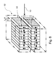
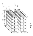
For a Extreme UltraViolet light source based on Free-Electron Laser, a planar undulator comprising alternating dipole magnets 52 is used, e.g., a pure permanent magnet (PPM) undulator with Nd2Fe14B blocks 50 as shown in Fig. 8 or a hybrid undulator comprising pure permanent magnets 50 and ferromagnetic poles 51 as shown in Fig. 9 , e.g. a high saturation cobalt steel such as vanadium permendur or a simple iron. For a hybrid undulator, the thickness of the pole and magnet is optimized in order to maximize the peak field. In Fig. 8 and 9, the arrows represent the direction of magnetization in the magnet blocks, of which a period is λu . The minimum distance between the magnet jaws is a gap g. The peak field Bu of the gap is estimated in terms of the gap g and period λu according to Bu =a[T]exp[b(g/λu )+c(g/λu )2] for gap range 0.1<g/λu <1, where α= 2.076 T, b=-3.24, c=0 for the pure permanent magnets planar undulator, α=3.694T , b=-5.068, c=1.520 for the hybrid undulator with vanadium permendur, and a=3.381T, b=-4.730, c=1.198 for the hybrid undulator with iron.
-
As shown in Fig. 10A and 10B, the undulator 13 comprises a rectangular box frame 53, a gap adjusting mechanism 54 and cooling elements 55. The permanent magnet blocks 52 is attached to a thick base plate of the box frame 53 made of aluminium material. The alignment and gap of the undulator are adjusted by controlling the distance between two base plates of the box frame 53 with 4 or 6 adjusting mechanisms 54. Two monolithic water cooling elements 55 fabricated from tubing are connected to each magnet block 52.
Beam separator
-
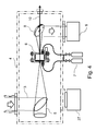
As shown in Fig. 11A, 11B and 11C, a decelerated electron beam 10 after saturation is bent by a dipole field of permanent magnet (a beam separator 16) made of NdFeB material and dumped to a beam dump 17 made of copper with a water cooling element 56. The permanent magnet dipole (PMD) 16, e.g., Halbach-type permanent magnet dipole, comprises 8 wedges of the NdFeB material, of which the magnetization direction is shown by the arrows in Fig. 11B. The dipole field BD of the Halbach-type permanent magnet dipole is given by BD = Br ln(r o /ri ), where Br is the tip field strength, ri is the bore radius and r 0 is the outer radius of the PMD. With Br =1.45T for NdFeB material, ri =5 mm and ro = 100 mm , one can obtain the dipole field BD =4.34T. The mechanical precision and field accuracy of the permanent magnet dipole 16 can be achieved by the insertion of a nonmagnetic precision cylinder 57 into the center of the permanent magnet dipole and by the housing case 58 outside the permanent magnet dipole. The electron beam 10 bent by the permanent magnet dipole field 16 is dumped to the copper beam dump 17, while the Extreme UltraViolet radiation 14 is extracted through a narrow Extreme UltraViolet output hole 59 machined in the beam dump 17 at the edge of the permanent magnet dipole bore. The permanent magnet dipole length required for deflecting d≈2ri [mm] is s given by L PMD[cm] =10[(ri /3.26mm)(Eb /1GeV)]1/2 for BD =4.34T (ro /ri = 20). Since electrons lose energy by a factor of 1/e; 0.37 over the radiation length X 0=1.44 cm via electromagnetic cascades in the copper beam dump, almost all electrons with energy 1 GeV lose their energy inside the copper block with length 10X 0∼15 cm and diameter 7X 0 ∼10 cm. Both permanent magnet dipole and beam dump are cooled down by the water cooling elements 56.
The Free-Electron Laser device
-
As shown in Fig. 12, the Free-Electron Laser device comprising the beam focusing system 12, the undulator 13 and the beam separator 16 and beam dump 17 is installed into vacuum chambers 11, 15 with vacuum pumping systems 28, 29 that maintain a pressure of the order of 10-4 Pa inside the chamber. The beam dump 17 connected to the beam separator 16 forms a monolithic device.
-
In self-amplified spontaneous emission (SASE) Free-Electron Laser process, coupling the electron bunch with a copropagating undulator radiation field induces the energy modulation of electrons that yields a current modulation of the bunch due to the dispersion of the undulator dipole fields, called microbunching. It means that the electrons are grouped into small bunches separated by a fixed distance that resonantly coincides with the wavelength of the radiation field. Consequently, the radiation field can be amplified coherently. When lacking an initial resonant radiation field, a seed may build up from spontaneous incoherent emission in the self-amplified spontaneous emission (SASE) process.
Design of Free-Electron Laser based Extreme UltraViolet light source
-
A design of Free-Electron Laser based Extreme UltraViolet light source is made by the one-dimensional Free-Electron Laser theory as follows. The Free-Electron Laser amplication takes place in the undulator with the undulator period
λu at the resonant wavelength given by
where
γ=
Eb /
mec2 is the relativistic factor of the electron beam energy
Eb , and
Ku =0.934
Bu [T]
λu [cm]=
γθe is the undulator parameter, which is related to the maximum electron deflection angle
θe .
-
In the high-gain regime required for the operation of a self-amplified spontaneous emission (SASE) Free-Electron Laser, an important parameter is the Pierce parameter
ρ FEL given by
where
Ib is the beam current,
IA =17kA is the Alfven current, σ
b is the root mean square (r.m.s) transverse size of the electron bunch, and the coupling factor is
Au =1 for a helical undulator and
Au =
J 0(ξ)
-J 1(ξ) for a planar undulator, where
and
J 0 and
J 1 are the Bessel functions of the first kind.
-
Another important dimensionless parameter is the longitudinal velocity spread A of the beam normalized by the Pierce parameter:
where σ
γ /
γ is the relative root mean square (r.m.s.) energy spread,
ε is the r.m.s. transverse emittance,
is the beta function provided by the guiding field (undulator plus external focusing) and
εn is the normalized emittance defined as
εn ≡
γε assuming that a beta function is constant along the length of the undulator.
-
A
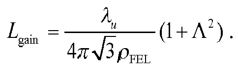
e-folding gain length
L gain over which the power grows exponentially according to exp(2
s/
L gain) is given by
-
In order to minimize the gain length, one needs a large Pierce parameter
ρ FEL and a normalized longitudinal velocity spread A sufficiently low compared to 1 that means a sufficiently small energy spread
σ γ/
γ and
ε. This expression applies to moderately small beam size σ
b such that the diffraction parameter
B? 1 where
B is defined as
-
A saturation length
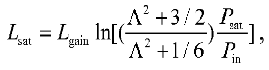
L sat required to saturate the amplification can be expressed as
where
P in and
P sat are an input and a saturated power.
-
The input
P in and saturated power
P sat are related to an electron beam power
Pb according to
where
NλX is the number of electrons per wavelength given by
N λ X =
IbλX /(
ec).
6.4. Embodiment of a Free-Electron Laser used as an Extreme UltraViolet source at 13,5 nm wavelength
-
A fiber laser driven Laser Plasma Accelerator (LPA) based Free-Electron Laser produced Extreme UltraViolet radiation source at λX =13.5 nm wavelength using the undulator with period λu =5 mm (Case A), 10 mm (Case B), 15 mm (Case C), 20 mm (Case D) and 25 mm (Case E), all cases of which have the gap-period ratio g/λu =0.2, e.g. g = 1 mm (Case A), 2 mm (Case B), 3 mm (Case C), 4 mm (Case D) and 5 mm (Case E), respectively. A hybrid undulator comprising NdFeB materials with grade N52, e.g., VACODYM 722HR, and ferromagnetic materials such as tempered Co-Fe alloys (vanadium permendur), e.g., VACOFLUX 50, provide the peak magnetic field B u[T]=3.694exp(-5.068×0.2+1.520×0.22)=1.425. The corresponding undulator parameter becomes Ku =0.1331λu [mm]=0.6655,1.331,1.9965,2.662,3.3275 for λu [mm]=5,10,15,20,25.
-
The electron beam energy
Eb required for producing the Extreme UltraViolet radiation at the wavelength
λX =13.5nm is given by
i.e.,
For Case A to E,
γ=475.6,835.7,1290,1834,2460 and
Eb [MeV]=243,427,659,937,1257.
-
The Laser Plasma Accelerator (LPA) can provide a high-peak current bunched beam, e.g., IA = 50 kA for electron charge Qb = 0.5 nC and bunch duration τb : 10 fs. A fiber laser pulse with wavelength λL =1µm after compression is focused on the entrance of gas cell at the normalized laser field a 0=2 corresponding to the laser intensity I=5.5×10¹⁸ Wcm-2. Self-guided propagation of such laser pulse in the gas cell requires the group velocity correction factor κ self=1.19 and the matched spot radius Rm ≡kprm =3.2. The wakefield reduction factor α due to loaded charge Qb is calculated from α 2+Cα 3/2-1=0 for the electron beam radius kp σ b =1, where the coefficients are C = 9.0,6.8,5.5,4.6,4.0 as α= 0.223,0.267,0.302,0.335,0.364, respectively, for Case A to E.
-
The important Laser Plasma Accelerator (LPA) parameters are provided as follows:
- (1) The operating plasma density; ne [1017cm-3]=8.3,5.6,4.2,3.2,2.6
- (2) The accelerator length; L acc[mm]=18,32,51,74,102
- (3) The required pulse duration; τL [fs]=46,56,65,73,82
- (4) The matched spot radius; rm [µm]= 19,23,27,30,34
- (5) The matched power; PL [TW] = 29,43,59,75,93
- (6) The required laser pulse energy; UL [J]=1.34,2.40,3.79,5.52,7.57
-
For the Free-Electron Laser operation, the coupling factor Au (ξ) are Au =0.9527,0.8696,0.8083,0.7711,0.7486 with ξ=0.09065,0.2349,0.3329,0.3899,0.4235 for Case A to E, respectively. The root mean square (r.m.s) transverse size of the electron bunch is set to σb = 25µm in the undulator and is usually much larger than the normalized transverse emittance εn of the order of 1 µm for the Laser Plasma Accelerator (LPA) produced electron beam. For the peak current Ib = 50 kA with the number of electrons per wavelength NλX =1.4×10⁷ and the diffraction parameter B ? 1, the important Free-Electron Laser parameters are given as follows according to the one-dimensional Free-Electron Laser theory:
- (1) The Pierce parameter; ρ FEL[%]=1.117,1.507,1.597,1.596,1.572
- (2) The longitudinal velocity spread; Λ≈1 for setting σγ/γ≈ρ FEL
- (3) The e-folding gain length; L gain[mm] = 41,61,86,115,146
- (4) The saturated power; P sat [GW]≅0.6ρ FEL P b=82,194,317,451,596
- (5) The input power; P in[MW]≈0.94,3.03,5.26,7.48,9.72
- (6) The saturation length; L sat[mm] =499,721,1016,1355,1723
- (7) The total number of periods; Nu =100,72,68,68,69.
- (8) The spectral bandwidth; ΔλX /λX [%]:1/Nu ≈1.0,1.4,1.5,1.5,1.5
- (9) The r.m.s. radiation cone angle;
- (10) The average power at the repetition frequency f rep[MHz];
assuming the radiation duration τX≈τb∼10 fs.
-
The repetition rate f rep to be required for generating the average Extreme UltraViolet power of P EUV = 1 kW yields f rep[MHz]≈P EUV/(PsatτX ) =1.22,0.515,0.315,0.223,0.168. For the production of 1 kW Extreme UltraViolet radiation, the average fiber laser power yields PLav [MW]≈ULf rep =1.63,1.24,1.19,1.22,1.27
-
Consequently, the minimum average laser power takes place for Case C with the undulator period 15 mm. The average beam power yields P bav[kW]=Qbf rep Eb ≈148,110,104,104,105. The efficiency of the electron beam acceleration is η laser→beam[%]=P bav/P Lav ≈9.1,8.9,8.7,8.5,8.3. The efficiency of the production of Extreme UltraViolet radiation yields η laser→EUV[%] = 0.061,0.081,0.084,0.082,0.079
-
Said Laser Plasma Accelerator (LPA) and Free-Electron Laser parameters for Case A to E producing the Extreme UltraViolet radiation of 1 kW at 13.5 nm wavelength are summarized as shown in Table 1.
Table I Examples of the fiber laser driven Laser Plasma Accelerator (LPA) based Free-Electron Laser Extreme Ultra Violet light source at 13.5 nm | Case | A | B | C | D | E |
| Fiber laser parameters | | | | | |
| Laser wavelength [µm] | 1 | 1 | 1 | 1 | 1 |
| Average laser power [MW] | 1.63 | 1.24 | 1.19 | 1.22 | 1.27 |
| Repetition rate [MHz] | 1.22 | 0.515 | 0.315 | 0.223 | 0.168 |
| Laser energy per pulse [J] | 1.34 | 2.40 | 3.79 | 5.52 | 7.57 |
| Peak power [TW] | 29 | 43 | 59 | 75 | 93 |
| Pulse duration [fs] | 46 | 56 | 65 | 73 | 82 |
| Matched spot radius [µm] | 19 | 23 | 27 | 30 | 34 |
| LPA parameters | | | | | |
| Electron beam energy [MeV] | 243 | 427 | 659 | 937 | 1257 |
| Plasma density [1017 cm-3] | 8.3 | 5.6 | 4.2 | 3.2 | 2.6 |
| Accelerator length [mm] | 18 | 32 | 51 | 74 | 102 |
| Charge per bunch [nC] | 0.5 | 0.5 | 0.5 | 0.5 | 0.5 |
| Field reduction factor α | 0.223 | 0.267 | 0.302 | 0.325 | 0.364 |
| Bunch duration [fs] | 10 | 10 | 10 | 10 | 10 |
| Energy spread [%] | ∼ 1.1 | ∼ 1.5 | ∼ 1.6 | ∼ 1.6 | ∼ 1.6 |
| Normalized emittance [mm mrad] | ∼ 1 | ∼ 1 | ∼ 1 | ∼ 1 | ∼ 1 |
| Transverse beam size [µm] | 25 | 25 | 25 | 25 | 25 |
| Peak current [kA] | 50 | 50 | 50 | 50 | 50 |
| Average beam power [kW] | 148 | 110 | 104 | 104 | 105 |
| Efficiency of laser to beam [%] | 9.1 | 8.9 | 8.7 | 8.5 | 8.3 |
| FEL parameters | | | | | |
| Undulator period [mm] | 5 | 10 | 15 | 20 | 25 |
| Radiation wavelength [nm] | 13.5 | 13.5 | 13.5 | 13.5 | 13.5 |
| Gap [mm] | 1 | 2 | 3 | 4 | 5 |
| Peak magnetic field [T] | 1.425 | 1.425 | 1.425 | 1.425 | 1.425 |
| Undulator parameter Ku | 0.666 | 1.33 | 2.00 | 2.66 | 3.33 |
| Pierce parameter [%] | 1.117 | 1.507 | 1.597 | 1.596 | 1.572 |
| Gain length [mm] | 41 | 61 | 86 | 115 | 146 |
| Saturation length [mm] | 499 | 721 | 1016 | 1355 | 1723 |
| Number of periods | 100 | 72 | 68 | 68 | 69 |
| Spectral bandwidth [%] | 1.0 | 1.4 | 1.5 | 1.5 | 1.5 |
| r.m.s. Radiation cone angle [µrad] | 116 | 97 | 82 | 71 | 63 |
| Input power [MW] | 0.94 | 3.03 | 5.26 | 7.48 | 9.72 |
| Saturated power [GW] | 82 | 194 | 317 | 451 | 596 |
| Duration of EUV pulse [fs] | 10 | 10 | 10 | 10 | 10 |
| Average EUV power [kW] | 1 | 1 | 1 | 1 | 1 |
| Efficiency of EUV generation [%] | 0.061 | 0.081 | 0.084 | 0.082 | 0.079 |
6.4. Embodiment of a Free-Electron Laser used as an Extreme UltraViolet source at 6,7 nm wavelength
-
A fiber laser driven Laser Plasma Accelerator (LPA) based Free-Electron Laser produced Extreme UltraViolet radiation source at λX = 6.7 nm wavelength using the undulator with period λu =5 mm (Case A), 10 mm (Case B), 15 mm (Case C), 20 mm (Case D) and 25 mm (Case E), all cases of which have the gap-period ratio g/λu = 0.2, e.g. g = 1 mm (Case A), 2 mm (Case B), 3 mm (Case C), 4 mm (Case D) and 5 mm (Case E), respectively. A hybrid undulator comprising NdFeB materials with grade N52, e.g., VACODYM 722HR, and ferromagnetic materials such as tempered Co-Fe alloys (vanadium permendur), e.g., VACOFLUX 50, provide the peak magnetic field Bu [T]=3.694exp(-5.068×0.2+1.520×0.22)=1.425. The corresponding undulator parameter becomes Ku =0.1331λu [mm]=0.6655,1.331,1.9965,2.662,3.3275 for λu [mm]=5,10,15,20,25.
-
The electron beam energy
Eb required for producing the Extreme UltraViolet radiation at the wavelength
λX = 6.7 is given by
i.e.,
For Case A to E,
γ=675.1,1186,1830,2604,3492 and
Eb [MeV]=345,606,935,1331,1784..
-
The Laser Plasma Accelerator (LPA) can provide a high-peak current bunched beam, e.g., IA =50 kA for electron charge Qb = 0.5 nC and bunch duration τb : 10 fs. A fiber laser pulse with wavelength λL =1µm after compression is focused on the entrance of gas cell at the normalized laser field a 0=2 corresponding to the laser intensity I=5.5×10¹⁸ Wcm-2. Self-guided propagation of such laser pulse in the gas cell requires the group velocity correction factor κ self=1.19 and the matched spot radius Rm ≡kprm =3.2. The wakefield reduction factor α due to loaded charge Qb is calculated from α 2+Cα 3/2-1=0 for the electron beam radius kp σ b =1, where the coefficients are C = 7.55,5.70,4.59,3.84,3.32 as α=0.249,0.295,0.335,0.369,0.400, respectively, for Case A to E.
-
The important Laser Plasma Accelerator (LPA) parameters are provided as follows:
- (1) The operating plasma density; ne [1017cm-3]=6.5,4.4,3.2,2.5,2.0
- (2) The accelerator length; L acc[mm]=26,47,74,109,150
- (3) The required pulse duration; τL [fs]=52,63,73,83,93
- (4) The matched spot radius; rm [µm]=21,26,30,34,38
- (5) The matched power; PL [TW] = 37,55,75,97,120
- (6) The required laser pulse energy; UL [J] =1.92,3.47,5.51,8.06,11.1
-
For the FEL operation, the coupling factor Au (ξ) are Au =0.9527,0.8696,0.8083,0.7711,0.7486 with ξ=0.09065,0.2349,0.3329,0.3899,0.4235 for Case A to E, respectively. The root mean square (r.m.s) transverse size of the electron bunch is set to σ b = 25µm in the undulator and is usually much larger than the normalized transverse emittance εn of the order of 1 µm for the Laser Plasma Accelerator (LPA) produced electron beam. For the peak current Ib = 50 kA with the number of electrons per wavelength NλX = 7×10⁶ and the diffraction parameter B ? 1, the important Free-Electron Laser parameters are given as follows according to the one-dimensional Free-Electron Laser theory:
- (1) The Pierce parameter; ρ FEL[%]=0.787,1.061,1.125,1.125,1.107
- (2) The longitudinal velocity spread; Λ≈1 for setting σγ/γ≈ρ FEL
- (3) The e-folding gain length; L gain[mm]= 58.4,86.6,123,163,207
- (4) The saturated power; P sat [GW]≅0.6ρ FEL P b=82,194,317,451,596
- (5) The input power; P in[MW]≈0.94,3.05,5.3,7.5,9.8
- (6) The saturation length; L sat[mm] = 709,1024,1441,1923,2445
- (7) The total number of periods; Nu =142,102,96,96,98.
- (8) The spectral bandwidth; ΔλX /λX [%]: 1/Nu ≈0.71,0.98,1.04,1.04,1.02
- (9) The r.m.s. radiation cone angle; θ rms[µrad]=69,57,48,42,37
- (10) The average power at the repetition frequency f rep[MHz];
P av[kW]: P sat τXf rep=(0.82,1.94,3.17,4.51,5.96)×f rep[MHz],
assuming the radiation duration τX ≈ τb ∼ 10 fs. The repetition rate f rep to be required for generating the average EUV power of P EUV = 1.5 kW yieldsf rep [MHz] ≈ P EUV / (P sat τX ) =1.83,0.773,0.473,0.332,0.252. For the production of 1.5 kW EUV radiation, the average fiber laser power yields PLav [MW]≈ULfrep =3.52,2.68,2.60,2.68,2.80
-
Consequently, the minimum average laser power takes place for Case C with the undulator period 15 mm. The average beam power yields P bav[kW]=Qbf repE b ≈316,234,221,221,225. The efficiency of the electron beam acceleration is η laser→beam[%] = P bav / P Lav ≈ 8.97,8.73,8.49,8.26,8.03. The efficiency of the production of Extreme UltraViolet radiation yields η laser→EUV[%] = 0.043,0.056,0.058,0.056,0.054.
-
Said Laser Plasma Accelerator (LPA) and Free-Electron Laser parameters for Case A to E producing the Extreme UltraViolet radiation of 1 kW at 6.7 nm wavelength are summarized as shown in Table 2.
Table 2 Examples of the fiber laser driven Laser Plasma Accelerator (LPA) based Free-Electron Laser Extreme UltraViolet light source. | Case | A | B | C | D | E |
| Fiber laser parameters | | | | | |
| Laser wavelength [µm] | 1 | 1 | 1 | 1 | 1 |
| Average laser power [MW] | 3.52 | 2.68 | 2.60 | 2.68 | 2.80 |
| Repetition rate [MHz] | 1.83 | 0.773 | 0.473 | 0.332 | 0.252 |
| Laser energy per pulse [J] | 1.92 | 3.47 | 5.51 | 8.06 | 11.1 |
| Peak power [TW] | 37 | 55 | 75 | 97 | 120 |
| Pulse duration [fs] | 52 | 63 | 73 | 83 | 93 |
| Matched spot radius [µm] | 21 | 26 | 30 | 34 | 38 |
| LPA parameters | | | | | |
| Electron beam energy [MeV] | 345 | 606 | 935 | 1331 | 1784 |
| Plasma density [1017 cm-3] | 6.5 | 4.4 | 3.2 | 2.5 | 2.0 |
| Accelerator length [mm] | 26 | 47 | 74 | 109 | 150 |
| Charge per bunch [nC] | 0.5 | 0.5 | 0.5 | 0.5 | 0.5 |
| Field reduction factor α | 0.249 | 0.295 | 0.335 | 0.369 | 0.400 |
| Bunch duration [fs] | 10 | 10 | 10 | 10 | 10 |
| Energy spread [%] | ∼ 0.8 | ∼ 1.1 | ∼ 1.1 | ∼ 1.1 | ∼ 1.1 |
| Normalized emittance [mm mrad] | ∼ 1 | ∼ 1 | ∼ 1 | ∼ 1 | ∼ 1 |
| Transverse beam size [µm] | 25 | 25 | 25 | 25 | 25 |
| Peak current [kA] | 50 | 50 | 50 | 50 | 50 |
| Average beam power [kW] | 316 | 234 | 221 | 221 | 225 |
| Efficiency of laser to beam [%] | 9.0 | 8.7 | 8.5 | 8.3 | 8.0 |
| FEL parameters | | | | | |
| Radiation wavelength [nm] | 6.7 | 6.7 | 6.7 | 6.7 | 6.7 |
| Undulator period [mm] | 5 | 10 | 15 | 20 | 25 |
| Gap [mm] | 1 | 2 | 3 | 4 | 5 |
| Peak magnetic field [T] | 1.425 | 1.425 | 1.425 | 1.425 | 1.425 |
| Undulator parameter Ku | 0.666 | 1.33 | 2.00 | 2.66 | 3.33 |
| Pierce parameter [%] | 0.787 | 1.06 | 1.125 | 1.125 | 1.107 |
| Gain length [mm] | 58.4 | 86.6 | 123 | 163 | 207 |
| Saturation length [mm] | 709 | 1024 | 1441 | 1923 | 2445 |
| Number of periods | 142 | 102 | 96 | 96 | 98 |
| Spectral bandwidth [%] | 0.71 | 0.98 | 1.04 | 1.04 | 1.02 |
| r.m.s. Radiation cone angle [µrad] | 69 | 57 | 48 | 42 | 37 |
| Input power [MW] | 0.94 | 3.05 | 5.3 | 7.5 | 9.8 |
| Saturated power [GW] | 82 | 194 | 317 | 451 | 596 |
| Duration of EUV pulse [fs] | 10 | 10 | 10 | 10 | 10 |
| Average EUV power [kW] | 1.5 | 1.5 | 1.5 | 1.5 | 1.5 |
| Efficiency of EUV generation [%] | 0.043 | 0.056 | 0.058 | 0.056 | 0.054 |
Citation List
Patent Literature
-
- (1) U.S. patent application No. 13/445,195, filed on Apr. 12, 2012 , entitled LASER PRODUCED PLASMA EUV LIGHT SOURCE, Pub. No. US 2012/0228526 A1 .
- (2) U.S. patent No. 4,761,584, Date of patent Aug. 2, 1988 , entitled STRONG PERMANENT MAGNET-ASSISTED ELECTROMAGNETIC UNDULATOR.
- (3) U.S. patent No. 5,019,863, Date of patent May 28, 1991 , entitled WEDGED-POLE HYBRID UNDULATOR.
- (4) International patent application No. PCT/US2012/050135 , filed on 09.08.2012, Pub. No. WO/2013/023053, Pub. Date, 14. 02.2013 , ENTITLED COMPACT UNDULATOR SYTEM AND METHODS.
Non patent Literature
-
- (1) A. Pak, K. A. Marsh, S. F. Martins, W. Lu, W. B. Mori, and C. Joshi, "Injection and Trapping of Tunnel-Ionized Electrons into Laser-Produced Wakes," Phys. Rev. Lett. 104, 025003 (2010).
- (2) C. McGuffey, A. G. R. Thomas, W. Schumaker, T. Matsuoka, V. Chvykov, F. J. Dollar, G. Kalintchenko, V. Yanovsky, A. Maksimchuk, K. Krushelnick, V. Y. Bychenkov, I. V. Glazyrin, and A. V. Karpeev, "Ionization Induced Trapping in a Laser Wakefield Accelerator," Phys. Rev. Lett. 104, 025004 (2010).
- (3) C. Xia, J. Liu, W. Wang, H. Lu, W. Cheng, A. Deng, W. Li, H. Zhang, X. Liang, Y. Leng, X. Lu, C. Wang, J. Wang, K. Nakajima, R. Li, and Z. Xu, "Effects of self-focusing on tunnel-ionization-induced injection in a laser wakefield accelerator," Phys. Plasmas 18, 113101 (2011).
- (3) J. S. Liu, C. Q. Xia, W. T. Wang, H. Y. Lu, C. Wang, A. H. Deng, W. T. Li, H. Zhang, X. Y. Liang, Y. X. Leng, X. M. Lu, C. Wang, J. Z. Wang, K. Nakajima, R. X. Li, and Z. Z. Xu, "All-Optical Cascaded Laser Wakefield Accelerator Using Ionization-Induced Injection," Phys. Rev. Lett. 107, 035001 (2011).
- (4) B. B. Pollock, C. E. Clayton, J. E. Ralph, F. Albert, A. Davidson, L. Divol, C. Filip, S. H. Glenzer, K. Herpoldt, W. Lu, K. A. Marsh, J. Meinecke, W. B. Mori, A. Pak, T. C. Rensink, J. S. Ross, J. Shaw, G. R. Tynan, C. Joshi, and D. H. Froula, "Demonstration of a Narrow Energy Spread, similar to 0.5 GeV Electron Beam from a Two-Stage Laser Wakefield Accelerator," Phys. Rev. Lett. 107, 045001 (2011).
- (5) M. Chen, E. Esarey, C. B. Schroeder, C. G. R. Geddes, and W. P. Leemans, "Theory of ionization-induced trapping in laser-plasma accelerators," Phys. ).
- (6) Kazuhisa Nakajima, Haiyang Lu, Xueyan Zhao, Baifei Shen, Ruxin Li and Zhizhan Xu, "100-GeV large scale laser plasma electron acceleration by a multi-PW laser," Chinese Optics Letters 11 (1), 013501-1∼15 (2013).
- (7) J. K. Lim, P. Frigola, G. Travish, J. B. Rosenzweig, S. G. Anderson, W. J. Brown, J. S. Jacob, C. L. Robbins, and A. M. Tremaine, "Adjustable, short focal length permanent-magnet quadrupole based electron beam final focus system", PHYSICAL REVIEW SPECIAL TOPICS - ACCELERATORS AND BEAMS 8, 072401-1∼17 (2005).
- (8) P. Elleaume, J. Chavanne, Bart Faatz", Nuclear Instruments and Methods in Physics Research A 455, 503-523 (2000).
- (9) T. Eichner, F. Grüner, S. Becker, M. Fuchs, D. Habs, R. Weingartner, U. Schramm, H. Backe, P. Kunz, and W. Lauth, "Miniature magnetic devices for laser-based, table-top free-electron lasers", PHYSICAL REVIEW SPECIAL TOPICS - ACCELERATORS AND BEAMS 10, 082401 (2007).
- (10) C. Pagani, E.L. Saldin, E.A. Schneidmiller, M.V. Yurkov, "Design considerations of 10 kW-scale extreme ultraviolet SASE FEL for lithography", Nuclear Instruments and Methods in Physics Research A 463, 9-25 (2001).