WO2015029771A1 - Dye-sensitized solar cell - Google Patents
Dye-sensitized solar cell Download PDFInfo
- Publication number
- WO2015029771A1 WO2015029771A1 PCT/JP2014/071285 JP2014071285W WO2015029771A1 WO 2015029771 A1 WO2015029771 A1 WO 2015029771A1 JP 2014071285 W JP2014071285 W JP 2014071285W WO 2015029771 A1 WO2015029771 A1 WO 2015029771A1
- Authority
- WO
- WIPO (PCT)
- Prior art keywords
- group
- dye
- carbon atoms
- arylalkyl
- sensitized solar
- Prior art date
Links
- SPYVCEHHBVWMKG-UHFFFAOYSA-O CC(CC=C)(CC=CCC(C1(C)CC=C)N(CCC(O)=O)c2c1ccc1c2cccc1)c(ccc1c2cccc1)c2[NH2+]CCC(O)=O Chemical compound CC(CC=C)(CC=CCC(C1(C)CC=C)N(CCC(O)=O)c2c1ccc1c2cccc1)c(ccc1c2cccc1)c2[NH2+]CCC(O)=O SPYVCEHHBVWMKG-UHFFFAOYSA-O 0.000 description 1
- IFLRQFXVBZSDRF-UHFFFAOYSA-O CC1(C)c(cc(cc2)OC)c2[N+](CCC(O)=O)=C1/C=C/C=C(\C1(C)C)/N(CCC(O)=O)c(cc2)c1cc2OC Chemical compound CC1(C)c(cc(cc2)OC)c2[N+](CCC(O)=O)=C1/C=C/C=C(\C1(C)C)/N(CCC(O)=O)c(cc2)c1cc2OC IFLRQFXVBZSDRF-UHFFFAOYSA-O 0.000 description 1
- VAZCTFZTTDVJIB-UHFFFAOYSA-O CC1(CC(C)=O)C(/C=C/C=C2\N(Cc(cc3)ccc3C(O)=O)C3C=CC([N+]([O-])=O)=CC3C2(C)CC(C)=O)=[N+](Cc(cc2)ccc2C(O)=O)C2C=CC([N+]([O-])=O)=CC12 Chemical compound CC1(CC(C)=O)C(/C=C/C=C2\N(Cc(cc3)ccc3C(O)=O)C3C=CC([N+]([O-])=O)=CC3C2(C)CC(C)=O)=[N+](Cc(cc2)ccc2C(O)=O)C2C=CC([N+]([O-])=O)=CC12 VAZCTFZTTDVJIB-UHFFFAOYSA-O 0.000 description 1
- PCENHFRYJILVRY-UHFFFAOYSA-O CC1(CC=C)c(c(cccc2)c2cc2)c2[N+](CCC(O)=O)=C1/C=C/C=C(/C1(C)CC=C)\N(CC(O)=O)c2c1c(cccc1)c1cc2 Chemical compound CC1(CC=C)c(c(cccc2)c2cc2)c2[N+](CCC(O)=O)=C1/C=C/C=C(/C1(C)CC=C)\N(CC(O)=O)c2c1c(cccc1)c1cc2 PCENHFRYJILVRY-UHFFFAOYSA-O 0.000 description 1
- GYYYVKLJQBXGSJ-UHFFFAOYSA-O CC1(CC=C)c(cc(cc2)C(O)=O)c2[N+](C)=C1/C=C/C=C(/C1(C)CC=C)\N(C)C(CC2)=C1C=C2C(O)=O Chemical compound CC1(CC=C)c(cc(cc2)C(O)=O)c2[N+](C)=C1/C=C/C=C(/C1(C)CC=C)\N(C)C(CC2)=C1C=C2C(O)=O GYYYVKLJQBXGSJ-UHFFFAOYSA-O 0.000 description 1
- NJHHZZMPLBOKMQ-UHFFFAOYSA-O CC1(CC=C)c2ccccc2[N+](CCCCCC(O)=O)=C1/C=C/C=C/C=C(/C12CCCC1)\N(CCCCCC(O)=O)c1c2cccc1 Chemical compound CC1(CC=C)c2ccccc2[N+](CCCCCC(O)=O)=C1/C=C/C=C/C=C(/C12CCCC1)\N(CCCCCC(O)=O)c1c2cccc1 NJHHZZMPLBOKMQ-UHFFFAOYSA-O 0.000 description 1
- 0 CC1(Cc2ccc[s]2)c2cc([N+]([O-])=O)ccc2[N+](CCOc2ccccc2)=C1C=CC=C(C1(C)Cc2ccc[s]2)N(C*)c2c1c(cccc1)c1cc2 Chemical compound CC1(Cc2ccc[s]2)c2cc([N+]([O-])=O)ccc2[N+](CCOc2ccccc2)=C1C=CC=C(C1(C)Cc2ccc[s]2)N(C*)c2c1c(cccc1)c1cc2 0.000 description 1
- DATKWASENWZPTL-UHFFFAOYSA-O CC1(Cc2ccccc2)c(c(cccc2)c2cc2)c2[N+](CCC(O)=O)=C1/C=C/C=C(\C1(C)Cc2ccccc2)/N(CCC(O)=O)c2c1c(cccc1)c1cc2 Chemical compound CC1(Cc2ccccc2)c(c(cccc2)c2cc2)c2[N+](CCC(O)=O)=C1/C=C/C=C(\C1(C)Cc2ccccc2)/N(CCC(O)=O)c2c1c(cccc1)c1cc2 DATKWASENWZPTL-UHFFFAOYSA-O 0.000 description 1
- PGNSAWHPSNNABB-UHFFFAOYSA-O CCCC1(C)c(cc(C)cc2)c2N(CC(O)=O)/C1=C\C=C\C1=[N+](CCC(O)=O)C(CCC(C)C2)=C2C1(C)CC=C Chemical compound CCCC1(C)c(cc(C)cc2)c2N(CC(O)=O)/C1=C\C=C\C1=[N+](CCC(O)=O)C(CCC(C)C2)=C2C1(C)CC=C PGNSAWHPSNNABB-UHFFFAOYSA-O 0.000 description 1
- OREJTBAQWQOLJT-UHFFFAOYSA-O CCCCOc(cc1)cc(C2(C)C)c1N(CC(O)=O)/C2=C/C=C/C(C1(C)C)=[N+](CC(O)=O)c(cc2)c1cc2OCCCC Chemical compound CCCCOc(cc1)cc(C2(C)C)c1N(CC(O)=O)/C2=C/C=C/C(C1(C)C)=[N+](CC(O)=O)c(cc2)c1cc2OCCCC OREJTBAQWQOLJT-UHFFFAOYSA-O 0.000 description 1
Images


Classifications
-
- H—ELECTRICITY
- H01—ELECTRIC ELEMENTS
- H01G—CAPACITORS; CAPACITORS, RECTIFIERS, DETECTORS, SWITCHING DEVICES OR LIGHT-SENSITIVE DEVICES, OF THE ELECTROLYTIC TYPE
- H01G9/00—Electrolytic capacitors, rectifiers, detectors, switching devices, light-sensitive or temperature-sensitive devices; Processes of their manufacture
- H01G9/20—Light-sensitive devices
- H01G9/2059—Light-sensitive devices comprising an organic dye as the active light absorbing material, e.g. adsorbed on an electrode or dissolved in solution
-
- C—CHEMISTRY; METALLURGY
- C09—DYES; PAINTS; POLISHES; NATURAL RESINS; ADHESIVES; COMPOSITIONS NOT OTHERWISE PROVIDED FOR; APPLICATIONS OF MATERIALS NOT OTHERWISE PROVIDED FOR
- C09B—ORGANIC DYES OR CLOSELY-RELATED COMPOUNDS FOR PRODUCING DYES, e.g. PIGMENTS; MORDANTS; LAKES
- C09B23/00—Methine or polymethine dyes, e.g. cyanine dyes
- C09B23/0008—Methine or polymethine dyes, e.g. cyanine dyes substituted on the polymethine chain
- C09B23/0033—Methine or polymethine dyes, e.g. cyanine dyes substituted on the polymethine chain the substituent being bound through a sulfur atom
-
- C—CHEMISTRY; METALLURGY
- C09—DYES; PAINTS; POLISHES; NATURAL RESINS; ADHESIVES; COMPOSITIONS NOT OTHERWISE PROVIDED FOR; APPLICATIONS OF MATERIALS NOT OTHERWISE PROVIDED FOR
- C09B—ORGANIC DYES OR CLOSELY-RELATED COMPOUNDS FOR PRODUCING DYES, e.g. PIGMENTS; MORDANTS; LAKES
- C09B23/00—Methine or polymethine dyes, e.g. cyanine dyes
- C09B23/0008—Methine or polymethine dyes, e.g. cyanine dyes substituted on the polymethine chain
- C09B23/005—Methine or polymethine dyes, e.g. cyanine dyes substituted on the polymethine chain the substituent being a COOH and/or a functional derivative thereof
- C09B23/0058—Methine or polymethine dyes, e.g. cyanine dyes substituted on the polymethine chain the substituent being a COOH and/or a functional derivative thereof the substituent being CN
-
- C—CHEMISTRY; METALLURGY
- C09—DYES; PAINTS; POLISHES; NATURAL RESINS; ADHESIVES; COMPOSITIONS NOT OTHERWISE PROVIDED FOR; APPLICATIONS OF MATERIALS NOT OTHERWISE PROVIDED FOR
- C09B—ORGANIC DYES OR CLOSELY-RELATED COMPOUNDS FOR PRODUCING DYES, e.g. PIGMENTS; MORDANTS; LAKES
- C09B23/00—Methine or polymethine dyes, e.g. cyanine dyes
- C09B23/0066—Methine or polymethine dyes, e.g. cyanine dyes the polymethine chain being part of a carbocyclic ring,(e.g. benzene, naphtalene, cyclohexene, cyclobutenene-quadratic acid)
-
- C—CHEMISTRY; METALLURGY
- C09—DYES; PAINTS; POLISHES; NATURAL RESINS; ADHESIVES; COMPOSITIONS NOT OTHERWISE PROVIDED FOR; APPLICATIONS OF MATERIALS NOT OTHERWISE PROVIDED FOR
- C09B—ORGANIC DYES OR CLOSELY-RELATED COMPOUNDS FOR PRODUCING DYES, e.g. PIGMENTS; MORDANTS; LAKES
- C09B23/00—Methine or polymethine dyes, e.g. cyanine dyes
- C09B23/02—Methine or polymethine dyes, e.g. cyanine dyes the polymethine chain containing an odd number of >CH- or >C[alkyl]- groups
- C09B23/06—Methine or polymethine dyes, e.g. cyanine dyes the polymethine chain containing an odd number of >CH- or >C[alkyl]- groups three >CH- groups, e.g. carbocyanines
-
- C—CHEMISTRY; METALLURGY
- C09—DYES; PAINTS; POLISHES; NATURAL RESINS; ADHESIVES; COMPOSITIONS NOT OTHERWISE PROVIDED FOR; APPLICATIONS OF MATERIALS NOT OTHERWISE PROVIDED FOR
- C09B—ORGANIC DYES OR CLOSELY-RELATED COMPOUNDS FOR PRODUCING DYES, e.g. PIGMENTS; MORDANTS; LAKES
- C09B23/00—Methine or polymethine dyes, e.g. cyanine dyes
- C09B23/02—Methine or polymethine dyes, e.g. cyanine dyes the polymethine chain containing an odd number of >CH- or >C[alkyl]- groups
- C09B23/08—Methine or polymethine dyes, e.g. cyanine dyes the polymethine chain containing an odd number of >CH- or >C[alkyl]- groups more than three >CH- groups, e.g. polycarbocyanines
- C09B23/083—Methine or polymethine dyes, e.g. cyanine dyes the polymethine chain containing an odd number of >CH- or >C[alkyl]- groups more than three >CH- groups, e.g. polycarbocyanines five >CH- groups
-
- C—CHEMISTRY; METALLURGY
- C09—DYES; PAINTS; POLISHES; NATURAL RESINS; ADHESIVES; COMPOSITIONS NOT OTHERWISE PROVIDED FOR; APPLICATIONS OF MATERIALS NOT OTHERWISE PROVIDED FOR
- C09B—ORGANIC DYES OR CLOSELY-RELATED COMPOUNDS FOR PRODUCING DYES, e.g. PIGMENTS; MORDANTS; LAKES
- C09B23/00—Methine or polymethine dyes, e.g. cyanine dyes
- C09B23/10—The polymethine chain containing an even number of >CH- groups
- C09B23/105—The polymethine chain containing an even number of >CH- groups two >CH- groups
-
- C—CHEMISTRY; METALLURGY
- C09—DYES; PAINTS; POLISHES; NATURAL RESINS; ADHESIVES; COMPOSITIONS NOT OTHERWISE PROVIDED FOR; APPLICATIONS OF MATERIALS NOT OTHERWISE PROVIDED FOR
- C09B—ORGANIC DYES OR CLOSELY-RELATED COMPOUNDS FOR PRODUCING DYES, e.g. PIGMENTS; MORDANTS; LAKES
- C09B57/00—Other synthetic dyes of known constitution
- C09B57/10—Metal complexes of organic compounds not being dyes in uncomplexed form
-
- H—ELECTRICITY
- H01—ELECTRIC ELEMENTS
- H01G—CAPACITORS; CAPACITORS, RECTIFIERS, DETECTORS, SWITCHING DEVICES OR LIGHT-SENSITIVE DEVICES, OF THE ELECTROLYTIC TYPE
- H01G9/00—Electrolytic capacitors, rectifiers, detectors, switching devices, light-sensitive or temperature-sensitive devices; Processes of their manufacture
- H01G9/20—Light-sensitive devices
- H01G9/2004—Light-sensitive devices characterised by the electrolyte, e.g. comprising an organic electrolyte
- H01G9/2013—Light-sensitive devices characterised by the electrolyte, e.g. comprising an organic electrolyte the electrolyte comprising ionic liquids, e.g. alkyl imidazolium iodide
-
- H—ELECTRICITY
- H01—ELECTRIC ELEMENTS
- H01G—CAPACITORS; CAPACITORS, RECTIFIERS, DETECTORS, SWITCHING DEVICES OR LIGHT-SENSITIVE DEVICES, OF THE ELECTROLYTIC TYPE
- H01G9/00—Electrolytic capacitors, rectifiers, detectors, switching devices, light-sensitive or temperature-sensitive devices; Processes of their manufacture
- H01G9/20—Light-sensitive devices
- H01G9/2004—Light-sensitive devices characterised by the electrolyte, e.g. comprising an organic electrolyte
- H01G9/2018—Light-sensitive devices characterised by the electrolyte, e.g. comprising an organic electrolyte characterised by the ionic charge transport species, e.g. redox shuttles
-
- H—ELECTRICITY
- H01—ELECTRIC ELEMENTS
- H01G—CAPACITORS; CAPACITORS, RECTIFIERS, DETECTORS, SWITCHING DEVICES OR LIGHT-SENSITIVE DEVICES, OF THE ELECTROLYTIC TYPE
- H01G9/00—Electrolytic capacitors, rectifiers, detectors, switching devices, light-sensitive or temperature-sensitive devices; Processes of their manufacture
- H01G9/20—Light-sensitive devices
- H01G9/2027—Light-sensitive devices comprising an oxide semiconductor electrode
- H01G9/2031—Light-sensitive devices comprising an oxide semiconductor electrode comprising titanium oxide, e.g. TiO2
-
- H—ELECTRICITY
- H05—ELECTRIC TECHNIQUES NOT OTHERWISE PROVIDED FOR
- H05K—PRINTED CIRCUITS; CASINGS OR CONSTRUCTIONAL DETAILS OF ELECTRIC APPARATUS; MANUFACTURE OF ASSEMBLAGES OF ELECTRICAL COMPONENTS
- H05K999/00—PRINTED CIRCUITS; CASINGS OR CONSTRUCTIONAL DETAILS OF ELECTRIC APPARATUS; MANUFACTURE OF ASSEMBLAGES OF ELECTRICAL COMPONENTS dummy group
- H05K999/99—PRINTED CIRCUITS; CASINGS OR CONSTRUCTIONAL DETAILS OF ELECTRIC APPARATUS; MANUFACTURE OF ASSEMBLAGES OF ELECTRICAL COMPONENTS dummy group dummy group
-
- H—ELECTRICITY
- H10—SEMICONDUCTOR DEVICES; ELECTRIC SOLID-STATE DEVICES NOT OTHERWISE PROVIDED FOR
- H10K—ORGANIC ELECTRIC SOLID-STATE DEVICES
- H10K85/00—Organic materials used in the body or electrodes of devices covered by this subclass
- H10K85/60—Organic compounds having low molecular weight
- H10K85/649—Aromatic compounds comprising a hetero atom
- H10K85/657—Polycyclic condensed heteroaromatic hydrocarbons
- H10K85/6572—Polycyclic condensed heteroaromatic hydrocarbons comprising only nitrogen in the heteroaromatic polycondensed ring system, e.g. phenanthroline or carbazole
-
- H—ELECTRICITY
- H10—SEMICONDUCTOR DEVICES; ELECTRIC SOLID-STATE DEVICES NOT OTHERWISE PROVIDED FOR
- H10K—ORGANIC ELECTRIC SOLID-STATE DEVICES
- H10K85/00—Organic materials used in the body or electrodes of devices covered by this subclass
- H10K85/30—Coordination compounds
- H10K85/331—Metal complexes comprising an iron-series metal, e.g. Fe, Co, Ni
-
- H—ELECTRICITY
- H10—SEMICONDUCTOR DEVICES; ELECTRIC SOLID-STATE DEVICES NOT OTHERWISE PROVIDED FOR
- H10K—ORGANIC ELECTRIC SOLID-STATE DEVICES
- H10K85/00—Organic materials used in the body or electrodes of devices covered by this subclass
- H10K85/60—Organic compounds having low molecular weight
- H10K85/649—Aromatic compounds comprising a hetero atom
- H10K85/652—Cyanine dyes
-
- Y—GENERAL TAGGING OF NEW TECHNOLOGICAL DEVELOPMENTS; GENERAL TAGGING OF CROSS-SECTIONAL TECHNOLOGIES SPANNING OVER SEVERAL SECTIONS OF THE IPC; TECHNICAL SUBJECTS COVERED BY FORMER USPC CROSS-REFERENCE ART COLLECTIONS [XRACs] AND DIGESTS
- Y02—TECHNOLOGIES OR APPLICATIONS FOR MITIGATION OR ADAPTATION AGAINST CLIMATE CHANGE
- Y02E—REDUCTION OF GREENHOUSE GAS [GHG] EMISSIONS, RELATED TO ENERGY GENERATION, TRANSMISSION OR DISTRIBUTION
- Y02E10/00—Energy generation through renewable energy sources
- Y02E10/50—Photovoltaic [PV] energy
- Y02E10/542—Dye sensitized solar cells
-
- Y—GENERAL TAGGING OF NEW TECHNOLOGICAL DEVELOPMENTS; GENERAL TAGGING OF CROSS-SECTIONAL TECHNOLOGIES SPANNING OVER SEVERAL SECTIONS OF THE IPC; TECHNICAL SUBJECTS COVERED BY FORMER USPC CROSS-REFERENCE ART COLLECTIONS [XRACs] AND DIGESTS
- Y02—TECHNOLOGIES OR APPLICATIONS FOR MITIGATION OR ADAPTATION AGAINST CLIMATE CHANGE
- Y02E—REDUCTION OF GREENHOUSE GAS [GHG] EMISSIONS, RELATED TO ENERGY GENERATION, TRANSMISSION OR DISTRIBUTION
- Y02E10/00—Energy generation through renewable energy sources
- Y02E10/50—Photovoltaic [PV] energy
- Y02E10/549—Organic PV cells
Definitions
- the present invention relates to a dye-sensitized solar cell.
- a dye-sensitized solar cell generally has an electrode having an oxide semiconductor as a carrier for the dye, and the dye absorbs incident light and is excited, and the excited dye carries an electron as a carrier.
- the photoelectric conversion is carried out by injecting into the above.
- this type of dye-sensitized solar cell can theoretically be expected to have high energy conversion efficiency among organic solar cells, and can be manufactured at a lower price than a solar cell using a conventional silicon semiconductor, It is considered very advantageous in terms of cost.
- the photoelectric conversion efficiency of the dye-sensitized solar cell is represented by the product of the generated current and the generated voltage.
- a technique for improving the generated current it has been studied to widen the light absorption wavelength range of the dye or to simultaneously use a plurality of dyes having different light absorption wavelength ranges.
- Organic dyes such as ruthenium complex dyes and cyanine dyes are widely known as dyes used in dye-sensitized solar cells. Among them, cyanine dyes have relatively high stability and can be easily used. Since it can be synthesized, various studies have been made.
- Patent Document 1 discloses a cyanine dye having a carboxylic acid group as an anchor group for adsorbing to an oxide semiconductor electrode.
- Patent Documents 1 and 2 and Patent Document 2 disclose a study of a dye used for a dye-sensitized solar cell to which a cobalt-based electrolyte is applied.
- An object of the present invention is to provide a dye-sensitized solar cell with high photoelectric conversion efficiency and durability.
- the present inventors have solved the above problem when a working electrode carrying a specific cyanine dye is used in a dye-sensitized solar cell using a non-iodine electrolyte. It has been found and led to the present invention.
- the present invention provides the following ⁇ 1> to ⁇ 5>.
- a dye-sensitized solar cell in which a working electrode and a counter electrode each having a dye-supported metal oxide electrode with a dye supported on a metal oxide layer are opposed to each other via an electrolyte layer,
- the dye contains a cyanine dye
- a dye-sensitized solar cell wherein the electrolyte in the electrolyte layer contains a cobalt-based electrolyte.
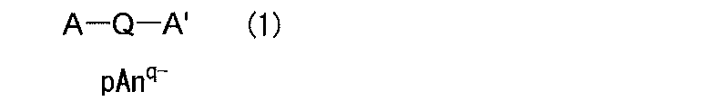
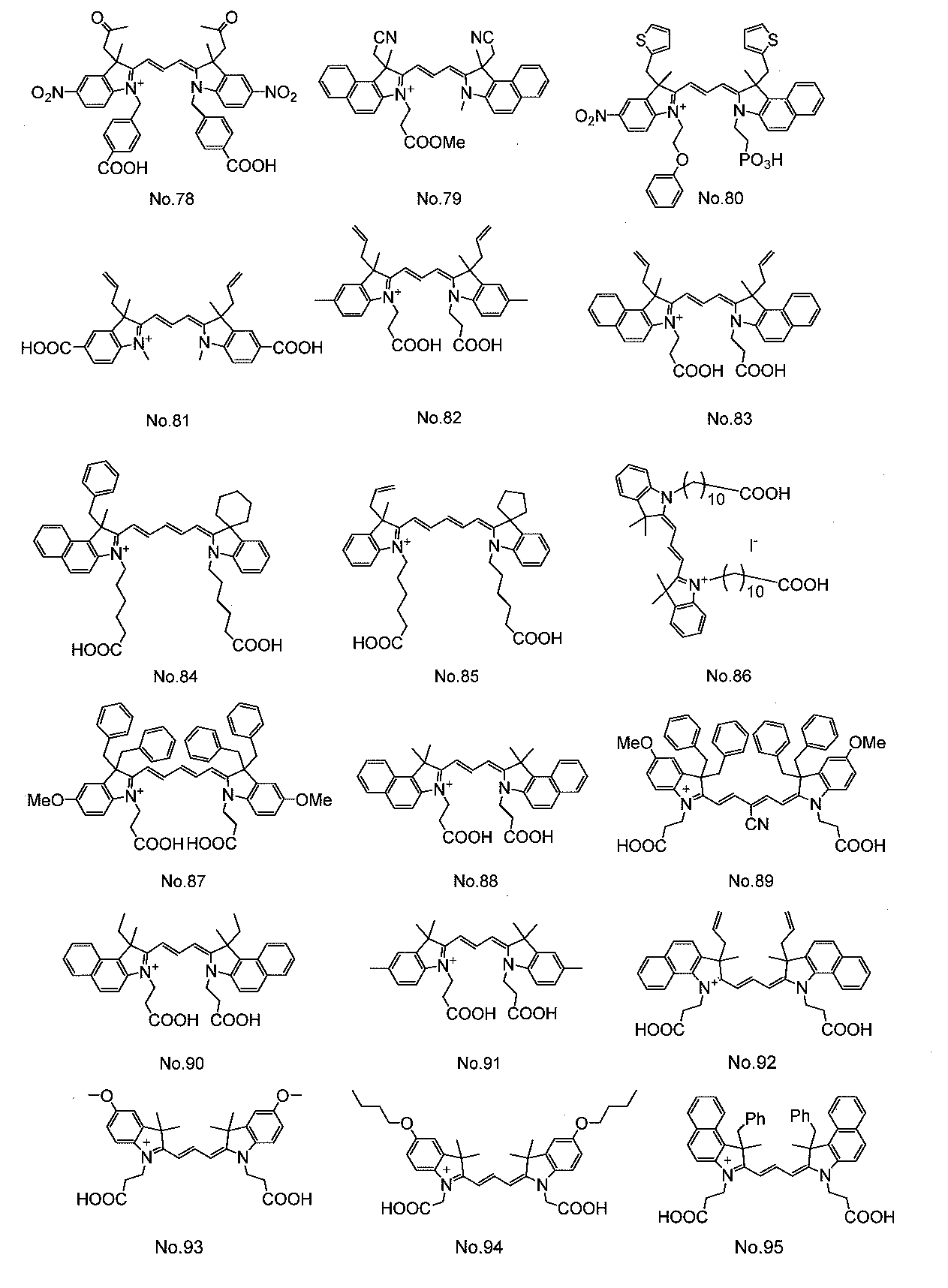
- cyanine dye is at least one compound represented by the following general formula (1).
- A represents a group selected from groups (a) to (m) of the following group I
- a ′ represents a group selected from groups (a ′) to (m ′) of the following group II
- Q represents a methine chain having 1 to 9 carbon atoms, and represents a linking group that may contain a ring structure in the chain, and the hydrogen atom in the methine chain is a hydroxyl group, a halogen atom, a cyano group, —NRR ′, aryl Group, an arylalkyl group or an alkyl group, and the —NRR ′, aryl group, arylalkyl group and alkyl group may be further substituted with a hydroxyl group, a halogen atom, a cyano group or NRR ′; Interrupted by —O
- R and R ′ represent an aryl group, an arylalkyl group or an alkyl group
- An q ⁇ represents a q-valent anion
- q represents 1 or 2
- p represents a coefficient for keeping the charge neutral.
- R 1 and R 1 ′ are a hydroxyl group, a halogen atom, a nitro group, a cyano group, a sulfonic acid group, a phosphoric acid group, a carboxylic acid group, an amino group, an amide group, a ferrocenyl group, an aryl group having 6 to 30 carbon atoms, An arylalkyl group having 7 to 30 carbon atoms or an alkyl group having 1 to 8 carbon atoms; The aryl group having 6 to 30 carbon atom
- R 2 to R 9 and R 2 ′ to R 9 ′ represent the same group or hydrogen atom as R 1 and R 1 ′
- X and X ′ represent an oxygen atom, a sulfur atom, a selenium atom, —CR 51 R 52 —, a cycloalkane-1,1-diyl group having 3 to 6 carbon atoms, —NH— or NY 2 —
- R 51 and R 52 represent the same group or hydrogen atom as R 1 and R 1 ′
- Y, Y ′ and Y 2 are each a hydrogen atom, a hydroxyl group, a halogen atom, a cyano group, a carboxylic acid group, an amino group, an amide group, a ferrocenyl group, a sulfonic acid group, a phosphoric acid group, —SiR 6 R 7 R 8 or An alkyl
- the compound represented by the general formula (1) is a compound represented by the above (a) to (e), (h) to (m), (a ′) to (e ′) or (h ′) to (m).
- A is a group selected from the above (a) or (h) to (k)
- a ′ is a group selected from the above (a ′) or (h ′) to (k ′)
- Q represents a methine chain having 1, 3, 5 or 7 carbon atoms, and represents a linking group that may contain a ring structure in the chain
- the hydrogen atom in the methine chain includes a hydroxyl group, a halogen atom, a cyano group, -NRR ', an aryl group, an arylalkyl group or an alkyl group may be substituted
- the -NRR', aryl group, arylalkyl group and alkyl group may be further substituted with a hydroxyl group, a halogen atom, a cyano group or NRR '.
- a dye-sensitized solar cell having a wide absorption wavelength region and excellent in adsorptivity (adhesiveness) to the metal oxide layer as well as energy transfer efficiency is realized.
- FIG. 1 It is a schematic diagram which shows the cross-sectional structure of an example of the dye-sensitized solar cell of this invention. It is an enlarged view of the principal part of the dye-sensitized solar cell of this invention shown in FIG.
- the constitution of the dye-sensitized solar cell of the present invention is the same as that of a conventional dye-sensitized solar cell except that an electrolyte other than iodine / iodide ions is used and a cyanine compound is used as the sensitizing dye. Can do.
- an electrolyte other than iodine / iodide ions is used and a cyanine compound is used as the sensitizing dye. Can do.
- the typical structural example of the dye-sensitized solar cell of this invention is demonstrated with reference to FIG. 1 and FIG.
- FIG. 1 schematically shows a cross-sectional configuration of an example of the dye-sensitized solar cell of the present invention
- FIG. 2 shows an extracted main part of the dye-sensitized solar cell shown in FIG. Is.
- the working electrode 10 and the counter electrode 20 are disposed to face each other with the electrolyte-containing layer 30 interposed therebetween, and at least one of the working electrode 10 and the counter electrode 20 is light transmissive. It is an electrode which has.
- the working electrode 10 includes, for example, a conductive substrate 11, a metal oxide semiconductor layer 12 provided on one surface thereof (a surface on the counter electrode 20 side), and a dye 13 supported on the metal oxide semiconductor layer 12. And have.
- the dye 13 contains at least one cyanine dye
- the electrolyte contained in the electrolyte-containing layer 30 is a quinone / hydroquinone electrolyte, (SCN) 2 / It contains at least one electrolyte selected from SCN ⁇ , (SeCN) 2 / SeCN ⁇ , a cobalt-based electrolyte, and a nitroxy radical compound-based electrolyte.
- SCN quinone / hydroquinone electrolyte
- a composite (support) comprising a metal oxide semiconductor layer 12 that is a carrier of the dye 13 and the dye 13 supported thereon corresponds to the dye-supported metal oxide electrode in the present invention.
- the working electrode 10 functions as a negative electrode for the external circuit.
- the conductive substrate 11 is obtained by providing a conductive layer 11B on the surface of an insulating substrate 11A.
- Examples of the material of the substrate 11A include insulating materials such as glass and plastic.
- the plastic is used, for example, in the form of a transparent polymer film.
- Examples of the plastic forming the transparent polymer film include tetraacetyl cellulose (TAC), polyethylene terephthalate (PET), polyethylene naphthalate (PEN), and syndiotactic polystyrene ( Examples thereof include SPS), polyphenylene sulfide (PPS), polycarbonate (PC), polyarylate (PAR), polysulfone (PSF), polyester sulfone (PES), polyetherimide (PEI), cyclic polyolefin, and brominated phenoxy.
- TAC tetraacetyl cellulose
- PET polyethylene terephthalate
- PEN polyethylene naphthalate
- syndiotactic polystyrene examples thereof include SPS), polyphenylene sulfide (PPS), polycarbonate (
- Examples of the conductive layer 11B include a conductive metal oxide thin film including indium oxide, tin oxide, indium-tin composite oxide (ITO), or tin oxide doped with fluorine (FTO: F—SnO 2 ). , Metal (Au), silver (Ag), platinum (Pt) and other metal thin films and metal meshes, those formed of conductive polymers, and the like.
- the conductive substrate 11 may be configured to have a single-layer structure with, for example, a conductive material.
- a conductive material examples include indium oxide, tin oxide, Examples thereof include conductive metal oxides such as indium-tin composite oxide or tin oxide doped with fluorine, metals such as gold, silver or platinum, and conductive polymers.
- the metal oxide semiconductor layer 12 is a carrier that supports the dye 13, and has, for example, a porous structure as shown in FIG.
- the metal oxide semiconductor layer 12 is formed of a dense layer 12A and a porous layer 12B.
- the dense layer 12A is formed at the interface with the conductive substrate 11, is preferably dense and has few voids, and more preferably is a film.
- the porous layer 12B is preferably formed on the surface in contact with the electrolyte-containing layer 30, has a large space and a large surface area, and more preferably has a structure in which porous fine particles are attached.
- the metal oxide semiconductor layer 12 may be formed to have, for example, a film-like single layer structure.
- the term “support” refers to a state in which the dye 13 is chemically or physically or electrically bonded or adsorbed to the porous layer 12B.
- Examples of the material (metal oxide semiconductor material) included in the metal oxide semiconductor layer 12 include titanium oxide, zinc oxide, tin oxide, niobium oxide, indium oxide, zirconium oxide, tantalum oxide, vanadium oxide, yttrium oxide, and oxide. Aluminum, magnesium oxide, etc. are mentioned. Among these, titanium oxide and zinc oxide are preferable as the metal oxide semiconductor material because high conversion efficiency can be obtained. Further, any one of these metal oxide semiconductor materials may be used alone, or two or more of them may be used in combination (mixed, mixed crystal, solid solution, surface coating, etc.). A combination of titanium oxide and zinc oxide can also be used.
- Examples of the method for forming the metal oxide semiconductor layer 12 having a porous structure include an electrolytic deposition method, a coating method, and a firing method.
- the metal oxide semiconductor layer 12 is formed by electrolytic deposition, the fine particles are deposited on the conductive layer 11B of the conductive substrate 11 in the electrolytic bath liquid containing the fine particles of the metal oxide semiconductor material and the metal.
- An oxide semiconductor material is deposited.
- a dispersion liquid metal oxide slurry
- a dispersion liquid metal oxide slurry in which fine particles of a metal oxide semiconductor material are dispersed is applied on the conductive substrate 11, and then in the dispersion liquid. Dry to remove the dispersion medium.
- the metal oxide semiconductor layer 12 is formed by the sintering method
- the metal oxide slurry is applied onto the conductive substrate 11 and dried, as in the coating method, and then fired.
- the metal oxide semiconductor layer 12 is formed by an electrolytic deposition method or a coating method
- a plastic material or a polymer film material having low heat resistance can be used as the substrate 11A, and thus a highly flexible electrode is manufactured. Can do.
- the metal oxide semiconductor layer 12 may be processed using an organic base, a urea derivative, or a cyclic sugar chain.
- organic base include organic bases such as diarylamine, triarylamine, pyridine, 4-t-butylpyridine, polyvinylpyridine, quinoline, piperidine, and amidine.
- the treatment may be performed before or after adsorbing the dye 13 described below.
- the treatment method includes dipping treatment. When the treatment agent is solid, the dipping treatment may be performed after dissolving in an organic solvent.
- the dye 13 is, for example, adsorbed to the metal oxide semiconductor layer 12, and is capable of injecting electrons into the metal oxide semiconductor layer 12 by absorbing light and being excited. Contains more than one type of dye (sensitizing dye). In the dye-sensitized solar cell of the present invention, the one containing at least one cyanine dye corresponds to the dye 13.
- the dye 13 only needs to contain at least one cyanine dye, and may contain other dyes as long as the effects of the present invention are not impaired.
- the cyanine dye used for the dye 13 is not particularly limited, but at least one cyanine dye represented by the general formula (1) can be preferably used.
- R 1 to R 9 and R 1 ′ to R 9 ′ and the halogen atom represented by R 51 and R 52 in X and X ′ include fluorine, chlorine, bromine and iodine.
- Examples of the aryl group having 6 to 30 carbon atoms include phenyl, naphthyl, 2-methylphenyl, 3-methylphenyl, 4-methylphenyl, 4-vinylphenyl, 3-iso-propylphenyl, 4-iso- Propylphenyl, 4-butylphenyl, 4-iso-butylphenyl, 4-tert-butylphenyl, 4-hexylphenyl, 4-cyclohexylphenyl, 4-octylphenyl, 4- (2-ethylhexyl) phenyl 4-stearylphenyl, 2,3-dimethylphenyl, 2,4-dimethylphenyl, 2,5-dimethylphenyl, 2,6-dimethyl
- arylalkyl group having 7 to 30 carbon atoms examples include benzyl, phenethyl, 2-phenylpropan-2-yl, diphenylmethyl, triphenylmethyl, styryl, cinnamyl, ferrocenylmethyl, ferrocenylpropyl and the like.
- alkyl group having 1 to 8 carbon atoms examples include methyl, ethyl, propyl, iso-propyl, butyl, sec-butyl, tert-butyl, iso-butyl, amyl, iso-amyl, tert-amyl, hexyl, 2 -Hexyl, 3-hexyl, cyclohexyl, 1-methylcyclohexyl, heptyl, 2-heptyl, 3-heptyl, iso-heptyl, tert-heptyl, 1-octyl, iso-octyl, and tert-octyl.
- the aryl group having 6 to 30 carbon atoms, the arylalkyl group having 7 to 30 carbon atoms, and the alkyl group having 1 to 8 carbon atoms are a hydroxyl group, a halogen atom, a nitro group, a cyano group, a sulfonic acid group, and phosphoric acid.
- examples of the group in which the alkyl group having 1 to 8 carbon atoms is substituted with a halogen atom include chloromethyl, dichloromethyl, trimethyl, fluoromethyl, difluoromethyl, trifluoromethyl, nonafluorobutyl, and the like.
- Examples of the group in which the alkyl group having 1 to 8 carbon atoms is interrupted by —O— include methyloxy, ethyloxy, iso-propyloxy, propyloxy, butyloxy, pentyloxy, iso-pentyloxy, hexyloxy, heptyloxy Alkoxy groups such as octyloxy, 2-ethylhexyloxy, 2-methoxyethyl, 2- (2-methoxy) ethoxyethyl, 2-ethoxyethyl, 2-butoxyethyl, 4-methoxybutyl, 3-methoxybutyl, etc.
- Examples of the group in which the alkyl group having 1 to 8 carbon atoms is substituted with a halogen atom and interrupted by —O— include, for example, chloromethyloxy, dichloromethyloxy, trimethylmethyloxy, fluoromethyloxy, difluoro And methyloxy, trifluoromethyloxy, nonafluorobutyloxy and the like.
- the cycloalkane-1,1-diyl group having 3 to 6 carbon atoms represented by X and X ′ includes cyclopropane-1,1-diyl, cyclobutane-1,1- Examples thereof include diyl, 2,4-dimethylcyclobutane-1,1-diyl, 3,3-dimethylcyclobutane-1,1-diyl, cyclopentane-1,1-diyl, cyclohexane-1,1-diyl and the like.
- a halogen atom represented by Y, Y ′ and Y 2 an alkyl group having 1 to 20 carbon atoms, an aryl group having 6 to 30 carbon atoms and an aryl having 7 to 30 carbon atoms
- alkyl group include the groups exemplified in the description of R 1 and the like, and hydrogen atoms in these substituents are a hydroxyl group, a halogen atom, a cyano group, a carboxylic acid group, an amino group, an amide group, a ferrocenyl group, A sulfonic acid group, a phosphoric acid group, —SiR 6 R 7 R 8 or a nitrogen group may be substituted in any number.
- alkyl group, the aryl group and the methylene group in the arylalkyl group in Y, Y ′, and Y 2 are —O—, —S—, —CO—, —COO—, —OCO—, —SO. 2 It may be interrupted with —NH—, —CONH—, —NHCO—, —N ⁇ CH— or —CH ⁇ CH—.
- Examples of the anion represented by An q ⁇ in the general formula (1) include an organic sulfonate anion.
- the organic sulfonate anion is a sulfonate anion having an organic group.
- Examples of the organic group include alkyl groups such as methyl, ethyl, propyl, butyl and cyclohexyl; aryl groups such as phenyl and naphthyl; and thienyl.
- heterocyclic groups such as pyrrolyl.
- the alkyl group, aryl group and heterocyclic group may be substituted with a halogen atom, carboxylic acid group, hydroxyl group, alkyl group, alkoxy group or the like.
- the organic sulfonate anion may be monovalent, divalent, or trivalent.
- Monovalent organic sulfonate anions include methane sulfonate anion, dodecyl sulfonate anion, benzene sulfonate anion, toluene sulfonate anion, trifluoromethane sulfonate anion, naphthalene sulfonate anion, diphenylamine-4-sulfonate anion 2-amino-4-methyl-5-chlorobenzenesulfonate anion, 2-amino-5-nitrobenzenesulfonate anion, JP-A-10-235999, JP-A-10-337959, JP-A-11- JP1020888, JP2000-108510, JP2000-168223, JP2001-209969, JP2001-322354, JP2006-248180, JP2006-297907.
- organic sulfonate anions such as sulfonate anions described in JP-A-8-253705, JP-A-2004-503379, JP-A-2005-336150, and International Publication 2006/28006.
- divalent organic sulfonate anion include benzene disulfonate anion, naphthalene disulfonate anion, naphthalene-1,5-disulfonate anion, 9,10-diethoxyanthracene-2,6-sulfonate anion, difluoro
- trivalent organic sulfonate anion examples include naphthalene-1,3,6-trisulfonate anion, trifluoroethane-sulfonate anion, and the like. It is done.
- monovalent anions include halogen anions such as chlorine anion, bromine anion, iodine anion, and fluorine anion; perchlorate anion, chlorate anion, thiocyanate anion, hexafluorophosphate anion, antimony hexafluoride Inorganic anions such as anion, boron tetrafluoride anion, nitrate anion, tetracyanoboron anion; octyl phosphate anion, dodecyl phosphate anion, octadecyl phosphate anion, phenyl phosphate anion, nonyl phenyl phosphate anion, 2, 2 ' -Organic phosphate anions
- Examples of the linking group that constitutes a methine chain having 1 to 9 carbon atoms represented by Q in the general formula (1) and may include a ring structure in the chain include the above (Q-1) to (Q-11) Is preferable because the production of the compound represented by the general formula (1) is easy.
- the number of carbon atoms in the methine chain having 1 to 9 carbon atoms is the carbon atom of the methine chain or a group that further substitutes the ring structure contained in the methine chain (for example, linking groups (Q-1) to (Q-11). ) Does not include carbon atoms at both ends in Z) or Z ′ or R 14 to R 19 if they contain carbon atoms.
- a compound in which Q is a group represented by the above (Q-1), (Q-2), (Q-6) or (Q-9) Is preferred.
- Examples of the halogen atom, aryl group, arylalkyl or alkyl group represented by R 14 , R 15 , R 16 , R 17 , R 18 , R 19 and Z ′ include those exemplified in the description of R 1 and the like.
- A is a group selected from the above (a) or (h) to (k)
- a ′ is a group selected from the above (a ′) or (h ′) to (k ′)
- Q represents a methine chain having 1, 3, 5 or 7 carbon atoms, and represents a linking group that may contain a ring structure in the chain
- the hydrogen atom in the methine chain includes a hydroxyl group, a halogen atom, a cyano group, -NRR ', an aryl group, an arylalkyl group or an alkyl group may be substituted
- the -NRR', aryl group, arylalkyl group and alkyl group may be further substituted with a hydroxyl group, a halogen atom, a cyano group or NRR '.
- R and R ′ may be interrupted by ⁇ CH—, and R and R ′ are an aryl group, an arylalkyl group or a group representing an alkyl group.
- the aryl group or the arylalkyl group having 7 to 30 carbon atoms is preferable because of its high adsorptivity to the carrier.
- Compounds having 30 arylalkyl groups are preferred, especially compounds having 1 to 20 carbon atoms substituted with 1 or 2 or more carboxylic acid groups are preferred, and particularly substituted with 1 or 2 or more carboxylic acid groups.
- Preferred are alkyl groups having 1 to 5 carbon atoms.
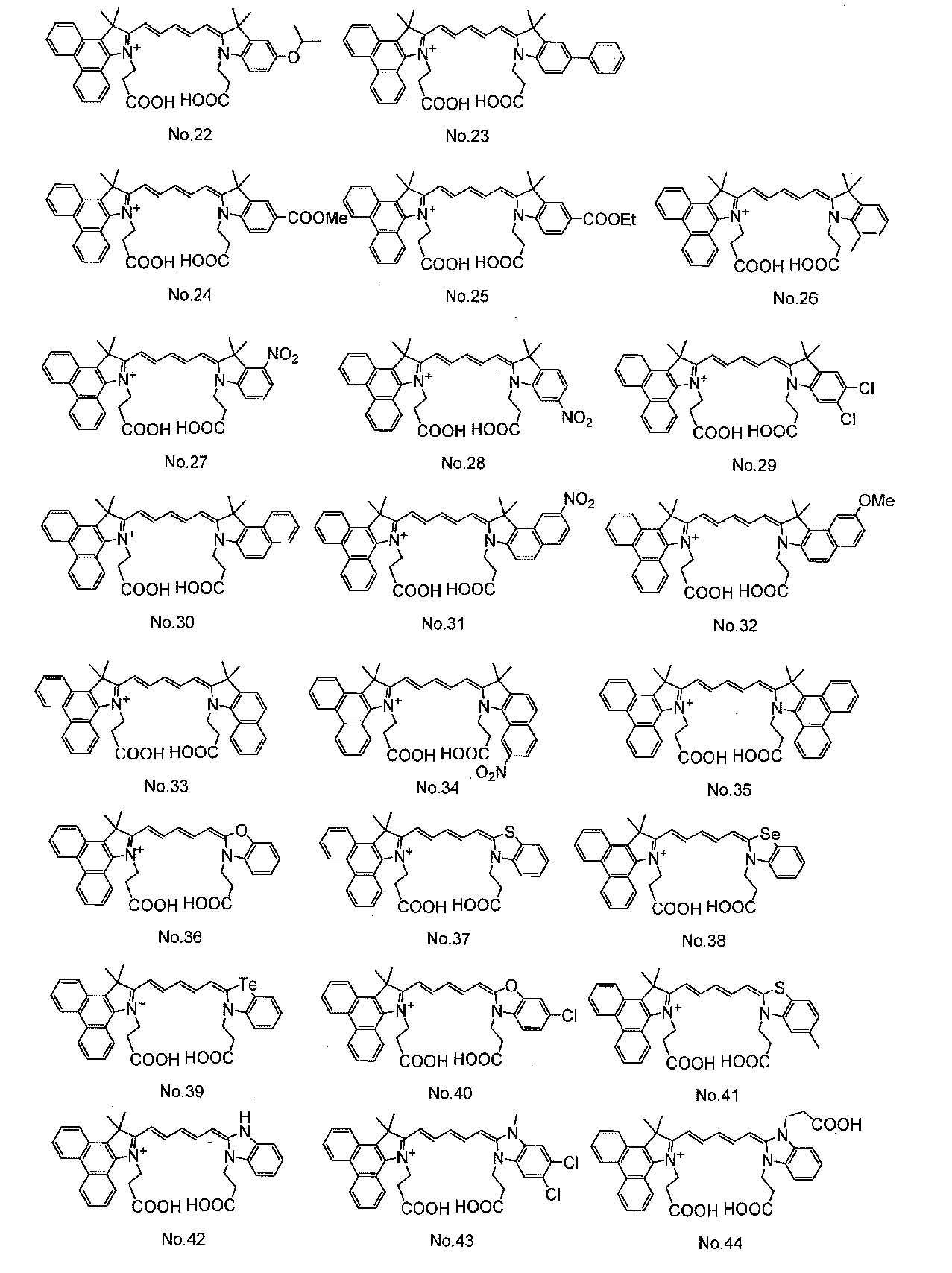
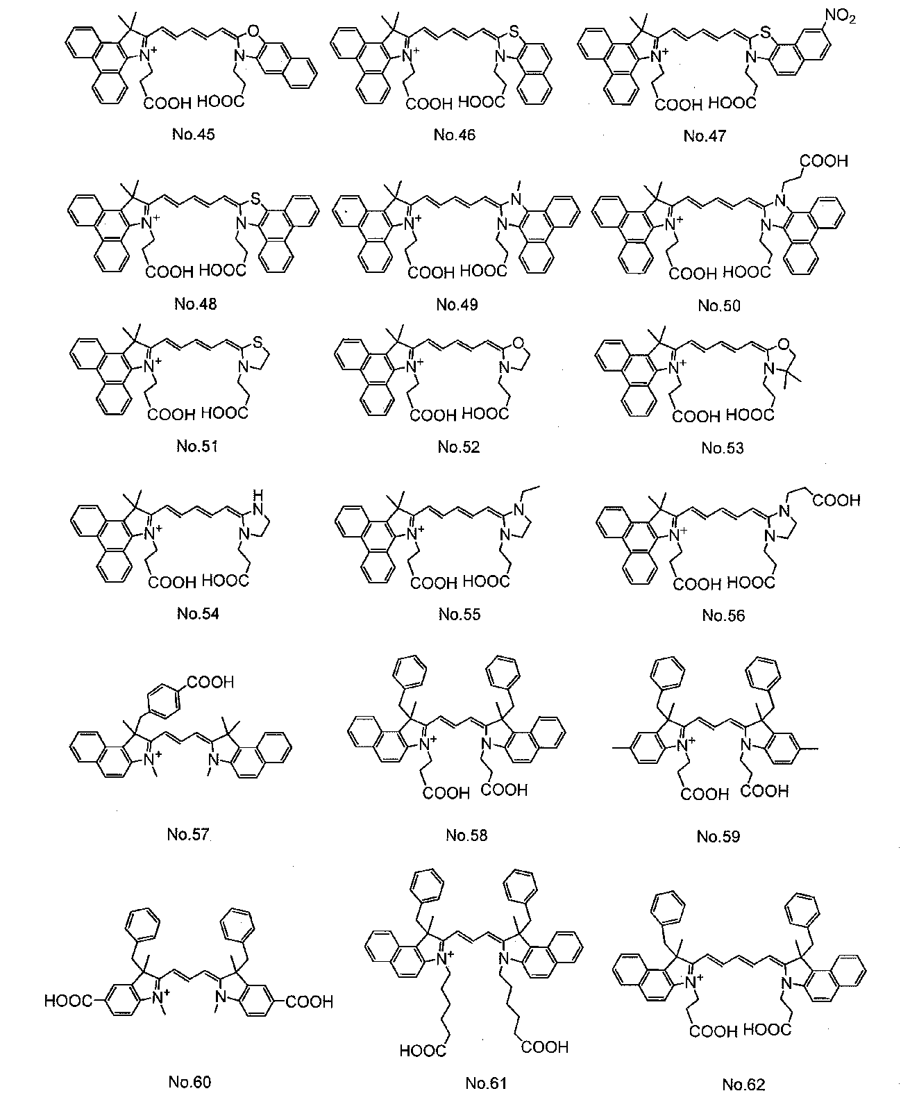
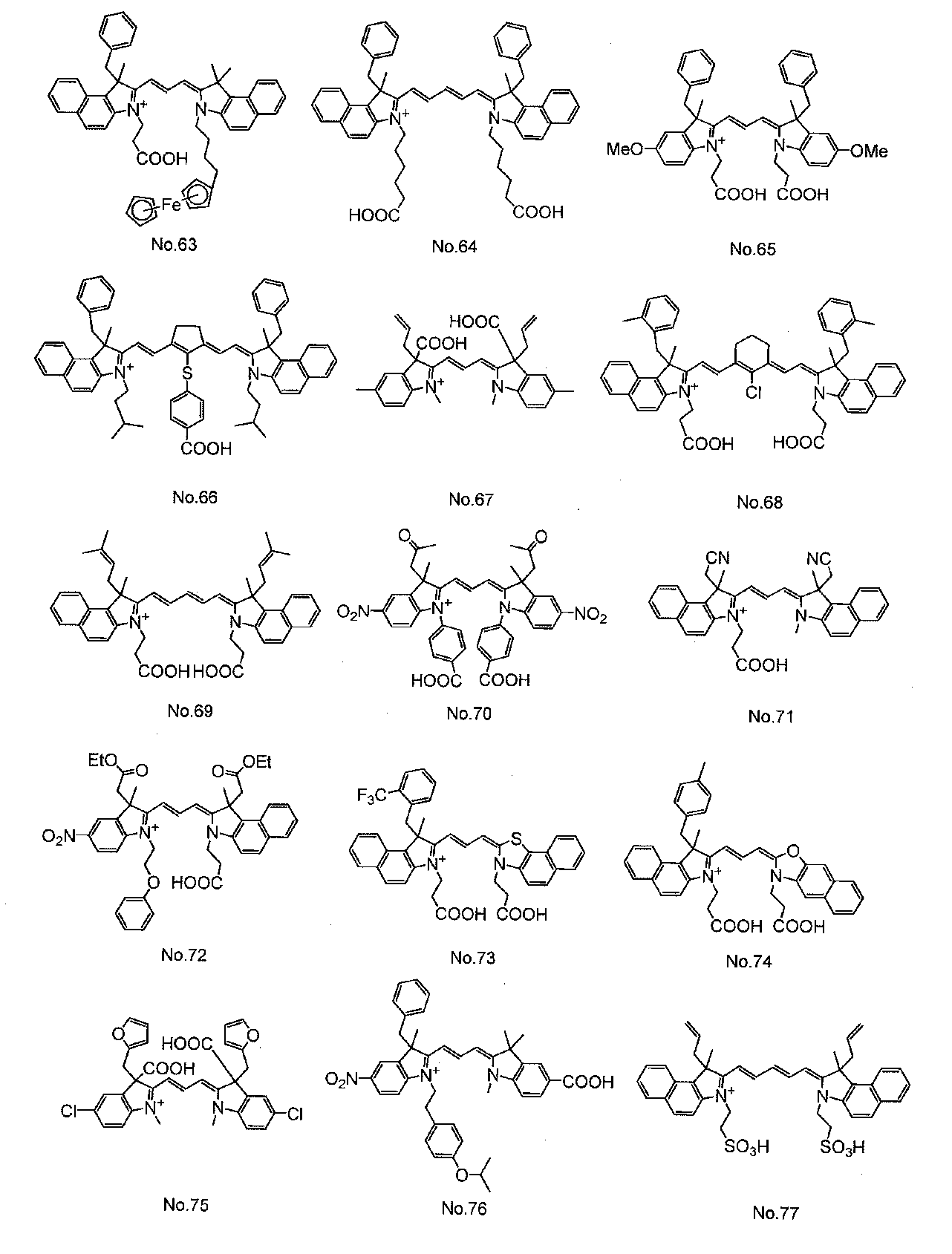
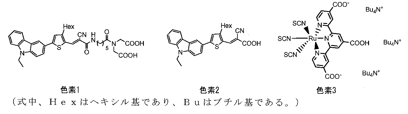
- cyanine dyes described in JP-A-2008-274230, JP-A-2010-157373, and International Publication WO2010 / 038589 are preferable. Used. In the formula, Me represents a methyl group, Et represents an ethyl group, and Ph represents a phenyl group.
- Examples of the compound that can be used as the dye 13 in addition to the compound represented by the general formula (1) include dye compounds other than the general formula (1) (hereinafter referred to as other organic dyes) and organometallic complex compounds.
- a dye having a group that can be adsorbed on the metal oxide semiconductor layer 12 (carrier) is preferable.
- Examples of the group that can be adsorbed on the metal oxide semiconductor layer 12 (support) include the above carboxylic acid group, sulfonic acid group, phosphoric acid group, SiR 6 R 7 R 8, and the like.
- organic dyes include eosin Y, dibromofluorescein, fluorescein, rhodamine B, pyrogallol, dichlorofluorescein, erythrosine B (erythrocin is a registered trademark), fluorescin, mercurochrome, merocyanine disazo dye, trisazo dye, anthraquinone dye, many Ring quinone dyes, indigo dyes, diphenylmethane dyes, trimethylmethane dyes, quinoline dyes, benzophenone dyes, naphthoquinone dyes, perylene dyes, fluorenone dyes, squarilium dyes, azurenium dyes, perinone dyes, Examples include quinacridone dyes, metal-free phthalocyanine dyes, metal-free porphyrin dyes, and metal-free azaporphyrin dyes.
- organometallic complex compound an ionic coordination bond formed between a nitrogen anion and a metal cation in an aromatic heterocyclic ring and a nonionic property formed between a nitrogen atom or a chalcogen atom and a metal cation
- Organometallic complex compounds having both coordination bonds, ionic coordination bonds formed by oxygen anions or sulfur anions and metal cations, and non-formations formed between nitrogen atoms or chalcogen atoms and metal cations
- organometallic complex compounds having both ionic coordination bonds.
- copper phthalocyanine, titanyl phthalocyanine, cobalt phthalocyanine, nickel phthalocyanine, iron phthalocyanine and other metal phthalocyanine dyes, metal naphthalocyanine dyes, metal porphyrin dyes, metal azaporphyrin dyes and ruthenium, iron, osmium are used.
- ruthenium complexes such as bipyridyl metal complexes, terpyridyl metal complexes, phenanthroline metal complexes, bicinchoninic acid metal complexes, azo metal complexes, and quinolinol metal complexes.
- the proportion of the cyanine dye is usually 10% by mass or more, preferably 30% by mass or more, and more preferably 40% by mass or more.
- dye 13 may contain the 1 type (s) or 2 or more types of additive other than the above-mentioned pigment
- the additive include an association inhibitor that suppresses association of the compound in the dye, and specifically, a cholic acid compound represented by the chemical formula (13). These may be used alone or in combination of two or more.
- R91 is an alkyl group having an acidic group or an alkoxysilyl group.
- R92 represents a group bonded to any of the carbon atoms constituting the steroid skeleton in the chemical formula, and represents a hydroxyl group, a halogen group, an alkyl group, an alkoxy group.
- t is an integer of 1 to 5.
- the bond between the carbon atoms constituting the steroid skeleton in the chemical formula may be a single bond or a double bond.
- the counter electrode 20 is, for example, a conductive substrate 21 provided with a conductive layer 22 and functions as a positive electrode for an external circuit.
- Examples of the material of the conductive substrate 21 include the same materials as those of the substrate 11 ⁇ / b> A of the conductive substrate 11 of the working electrode 10.
- the conductive layer 22 includes one type or two or more types of conductive material and a binder as necessary. Examples of the conductive material used for the conductive layer 22 include platinum, gold, silver, copper (Cu), rhodium (Rh), ruthenium (Ru), aluminum (Al), magnesium (Mg), and indium (In). Examples include metals, carbon (C), and conductive polymers.
- binder used for the conductive layer 22 examples include acrylic resin, polyester resin, phenol resin, epoxy resin, cellulose, melamine resin, fluoroelastomer, and polyimide resin.
- the counter electrode 20 may have a single layer structure of the conductive layer 22, for example.
- the electrolyte-containing layer 30 used in the present invention includes a redox electrolyte having a cobalt-based redox couple.
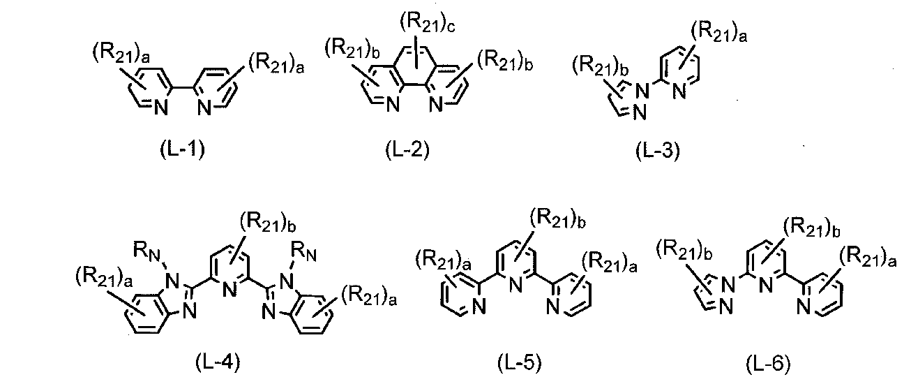
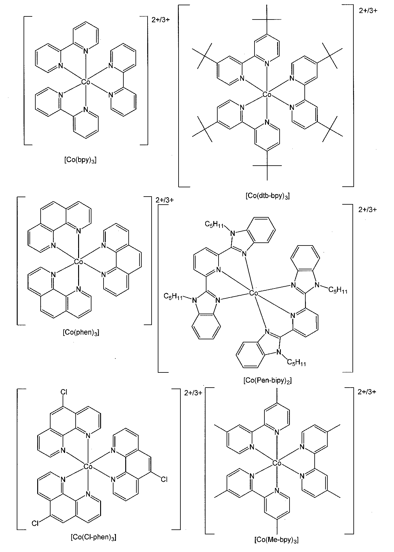
- cobalt-based redox pairs include combinations of divalent and trivalent cobalt complexes.
- Examples of the combination of the above divalent and trivalent cobalt complexes include compounds represented by the following general formula (2). (Wherein L represents a monodentate to tridentate ligand, n1 represents an integer of 2 to 6) X represents a counterion when a counterion is required to neutralize the charge, and n2 represents Represents the coefficient that keeps the charge neutral.)
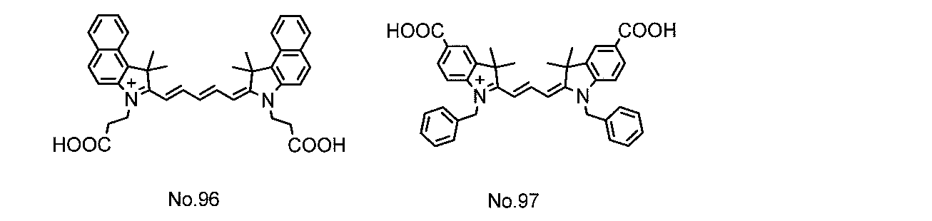
- the monodentate to tridentate ligand represented by L in the general formula (2) is not particularly limited, and known ligands are used, but the following general formulas (L-1) to (L-6) are preferable. At least one bidentate or tridentate ligand represented by any of the above. More preferably, L is any one or more selected from bidentate or tridentate ligands represented by general formulas (L-1) to (L-6), particularly preferably. (L-1), (L-2) or (L-4). In addition, examples of known ligands represented by L include halogen atoms.
- R 21 represents the same group as R 1 above, R N represents the same group as Y above, a represents an integer of 0 to 4, and b represents an integer of 0 to 3) And c represents an integer of 0 to 2.
- X in the general formula (2) neutralizes the charge, and may be a positive ion or a negative ion.
- examples include an ammonium ion, an alkali metal ion, and a proton.
- a negative ion the same group as the above-described An is exemplified.
- X in the general formula (2) is preferably a negative ion, and more preferably the same anion as the anion of the cyanine dye.
- the mass ratio of the divalent cobalt complex to the trivalent cobalt complex is not limited, but usually the former: the latter is used in the range of 100: 100 to 100: 1.
- the ratio is preferably 100: 50 to 100: 5, and more preferably 100: 35 to 100: 8.
- cation in the cobalt complex represented by the general formula (2) include the cations shown in the following [Chemical Formula 6].
- the cobalt-based electrolyte used in the present invention is not limited to these.
- the electrolyte-containing layer 30 may contain other electrolytes in addition to the cobalt-based electrolyte as long as the effects of the present invention are not impaired.
- Other electrolytes include, for example, a combination of a halide salt and a simple halogen, such as a combination of iodide salt and simple iodine, or a combination of bromide salt and bromine, quinone / hydroquinone, nitro Xyl radical compound system, Cu complex system, thiolate / disulfide complex system and the like can be mentioned.
- halide salt examples include cesium halide, quaternary alkylammonium halides, imidazolium halides, thiazolium halides, oxazolium halides, quinolinium halides and pyridinium halides.
- examples of the iodide salt include cesium iodide, tetraethylammonium iodide, tetrapropylammonium iodide, tetrabutylammonium iodide, tetrapentylammonium iodide, tetrahexylammonium iodide, and tetraheptyl.
- Quaternary alkylammonium iodides such as ammonium iodide or trimethylphenylammonium iodide, imidazolium iodides such as 3-methylimidazolium iodide or 1-propyl-2,3-dimethylimidazolium iodide, 3-ethyl-2-methyl-2-thiazolium iodide, 3-ethyl-5- (2-hydroxyethyl) -4-methylthiazolium iodide or 3-ethyl-2-methylbenzothiazolium iodide Cheer such as de Lithium iodides, oxazolium iodides such as 3-ethyl-2-methyl-benzoxazolium iodide, quinolinium iodides such as 1-ethyl-2-methylquinolinium iodide, Examples include pyridinium iodides. Examples of the bromide salt include qua
- the proportion of the cobalt-based electrolyte in the electrolyte contained in the electrolyte-containing layer 30 is preferably 30% by mass or more, more preferably 50% by mass or more, and 70 It is particularly preferable that the content is at least mass%.
- the electrolyte selected is preferably 30% by mass or more, more preferably 50% by mass or more, and particularly preferably 70% by mass or more.
- the electrolyte-containing layer 30 may be a liquid electrolyte (electrolytic solution) obtained by dissolving the above-described redox electrolyte in a solvent, or a solid polymer electrolyte in which the electrolytic solution is held in a polymer substance. May be.
- a quasi-solid (paste-like) electrolyte containing a mixture of an electrolytic solution and a particulate carbon material such as carbon black may be used.
- Such a redox electrolyte may contain an ionic liquid or an organic solvent. It does not specifically limit as an ionic liquid, A well-known ionic liquid can be used.
- Organic solvents include those that are electrochemically inactive, such as acetonitrile, tetrahydrofuran, propionitrile, butyronitrile, methoxyacetonitrile, 3-methoxypropionitrile, valeronitrile, dimethyl carbonate, ethyl methyl carbonate, ethylene Examples thereof include carbonate, propylene carbonate, N-methylpyrrolidone, pentanol, quinoline, N, N-dimethylformamide, ⁇ -butyrolactone, dimethyl sulfoxide, propylene carbonate, and 1,4-dioxane.
- the ionic liquid and the organic solvent can be used at the same time, and a plurality of types can be used.
- the electrolyte-containing layer 30 has a non-cyclic saccharide (Japanese Patent Laid-Open No. 2005-093313) and a pyridine compound (Japanese Patent Laid-Open No. 2003-2003) for the purpose of improving the power generation efficiency and durability of the dye-sensitized solar cell. 331936), urea derivatives (Japanese Patent Laid-Open No. 2003-168493) and the like may be added.
- the dye-sensitized solar cell of the present invention can be manufactured, for example, as follows.
- the working electrode 10 is produced.
- the metal oxide semiconductor layer 12 having a porous structure is formed on the surface of the conductive substrate 11 on which the conductive layer 11B is formed by electrolytic deposition or firing.
- electrolytic deposition for example, an electrolytic bath containing a metal salt to be a metal oxide semiconductor material is set to a predetermined temperature while bubbling with oxygen or air, and the conductive substrate 11 is placed therein. Immerse and apply a constant voltage between the counter electrode. Thereby, a metal oxide semiconductor material is deposited on the conductive layer 11B so as to have a porous structure.
- the counter electrode may be appropriately moved in the electrolytic bath.
- a metal oxide slurry prepared by dispersing a powder of a metal oxide semiconductor material in a dispersion medium is applied to the conductive substrate 11 and dried, followed by firing. Have a porous structure. Subsequently, a dye solution in which a dye 13 containing a cyanine dye is dissolved in an organic solvent is prepared. By immersing the conductive substrate 11 on which the metal oxide semiconductor layer 12 is formed in this dye solution, the metal oxide semiconductor layer 12 carries the dye 13.
- the concentration of the dye 13 in the dye solution is preferably 1.0 ⁇ 10 ⁇ 5 to 1.0 ⁇ 10 ⁇ 3 mol / dm 3 , and preferably 5.0 ⁇ 10 ⁇ 5 to 5.0 ⁇ 10 ⁇ 4 mol / dm. 3 is more preferable.
- the organic solvent used in the dye solution is not particularly limited as long as it can dissolve the dye 13, and specific examples thereof include hydrocarbons such as toluene, benzene and xylene; alcohols such as methanol, ethanol and t-butanol.
- Ether ethers such as methyl cellosolve, ethyl cellosolve, butyl cellosolve and butyl diglycol; ketones such as acetone, methyl ethyl ketone, methyl isobutyl ketone, cyclohexanone and diacetone alcohol; esters such as ethyl acetate, butyl acetate and methoxyethyl acetate; Acrylic acid esters such as ethyl acrylate and butyl acrylate; fluorinated alcohols such as 2,2,3,3-tetrafluoropropanol; chlorinated hydrocarbons such as methylene dichloride, dichloroethane and chloroform; acetonite Le, include tetrahydrofuran, may be mixed with these organic solvents arbitrarily.
- alcohols are used.
- the counter electrode 20 is produced by forming the conductive layer 22 on one surface of the conductive substrate 21.
- the conductive layer 22 is formed, for example, by sputtering a conductive material.
- a spacer such as a sealant so that the surface of the working electrode 10 carrying the dye 13 and the surface of the counter electrode 20 on which the conductive layer 22 is formed face each other while maintaining a predetermined distance.
- the whole is sealed except for the electrolyte inlet.
- an electrolyte solution is injected between the working electrode 10 and the counter electrode 20, and then the injection port is sealed to form the electrolyte containing layer 30.
- the dye-sensitized solar cell 100 shown in FIGS. 1 and 2 is completed.
- the dye-sensitized solar cell 100 described in the above embodiment was manufactured by the following procedure.
- ⁇ Production of titanium oxide carrier (working electrode) (conductive substrate 11)> A conductive substrate 11 made of a conductive glass substrate (F—SnO 2 ) having a length of 2.0 cm ⁇ width 1.5 cm ⁇ thickness 1.1 mm was prepared. Subsequently, the conductive substrate 11, so as to surround the square vertical 0.5cm ⁇ horizontal 0.5cm attaching the masking tape having a thickness of 70 [mu] m, and uniform metal oxide slurry 3 cm 3 thickness portion of the quadrangle It was applied and dried. As the metal oxide slurry, a suspension of titanium oxide powder (TiO 2 , Ti-Nanoxide D manufactured by Solaronix) in water so as to be 10% by weight was used. Subsequently, the masking tape on the conductive substrate 11 was peeled off, and this substrate was baked at 450 ° C. in an electric furnace to form a metal oxide semiconductor layer 12 having a thickness of about 5 ⁇ m.
- TiO 2 Ti-Nanoxide D manufactured by Solaron
- the produced working electrode 10 and the counter electrode 20 produced by coating graphite particles (conductive layer 22) on an ITO electrode (manufactured by Nishinoda Electric Co., Ltd.) as a conductive substrate 21.
- the electrolyte-containing layer 30 is placed between the spacers (63 ⁇ m), the electrolyte-containing layer 30 is disposed between them, and these are fixed with clips, and the electrolyte-containing layer 30 is infiltrated with the electrolyte solution described in [Table 1] to increase the dye concentration.
- a sensitive solar cell was produced. Covering the cell top with mask openings 1cm 2, AM-1.5G, was measured with a solar simulator of 100 mW / cm 2. The results are shown in [Table 1].
Abstract
Description
例えば、特許文献1には、酸化物半導体電極に吸着するためのアンカー基としてカルボン酸基を有するシアニン系色素が開示されている。 The photoelectric conversion efficiency of the dye-sensitized solar cell is represented by the product of the generated current and the generated voltage. As a technique for improving the generated current, it has been studied to widen the light absorption wavelength range of the dye or to simultaneously use a plurality of dyes having different light absorption wavelength ranges. Organic dyes such as ruthenium complex dyes and cyanine dyes are widely known as dyes used in dye-sensitized solar cells. Among them, cyanine dyes have relatively high stability and can be easily used. Since it can be synthesized, various studies have been made.
For example, Patent Document 1 discloses a cyanine dye having a carboxylic acid group as an anchor group for adsorbing to an oxide semiconductor electrode.
色素が、シアニン色素を含有するものであり、
電解質層中の電解質が、コバルト系電解質を含有することを特徴とする色素増感型太陽電池。 <1> A dye-sensitized solar cell in which a working electrode and a counter electrode each having a dye-supported metal oxide electrode with a dye supported on a metal oxide layer are opposed to each other via an electrolyte layer,
The dye contains a cyanine dye,
A dye-sensitized solar cell, wherein the electrolyte in the electrolyte layer contains a cobalt-based electrolyte.
(式中、Aは下記の群Iの(a)~(m)から選ばれる基を表し、A' は下記の群IIの(a’)~(m’)から選ばれる基を表し、
Qは炭素原子数1~9のメチン鎖を構成し、鎖中に環構造を含んでもよい連結基を表し、該メチン鎖中の水素原子は水酸基、ハロゲン原子、シアノ基、-NRR’、アリール基、アリールアルキル基またはアルキル基で置換されていてもよく、該-NRR’、アリール基、アリールアルキル基およびアルキル基は更に水酸基、ハロゲン原子、シアノ基またはNRR’で置換されていてもよく、-O-、-S-、-CO-、-COO-、-OCO-、-SO2-、-NH-、-CONH-、-NHCO-、-N=CH-または-CH=CH-で中断されてもよく、
RおよびR’は、アリール基、アリールアルキル基またはアルキル基を表し、
Anq-はq価のアニオンを表し、qは1または2を表し、pは電荷を中性に保つ係数を表す。)

(式中、環Cおよび環C’は、ベンゼン環、ナフタレン環、フェナントレン環またはピリジン環を表し、
R1およびR1’は、水酸基、ハロゲン原子、ニトロ基、シアノ基、スルホン酸基、リン酸基、カルボン酸基、アミノ基、アミド基、フェロセニル基、炭素原子数6~30のアリール基、炭素原子数7~30のアリールアルキル基または炭素原子数1~8のアルキル基を表し、
該炭素原子数6~30のアリール基、炭素原子数7~30のアリールアルキル基および炭素原子数1~8のアルキル基は、水酸基、ハロゲン原子、ニトロ基、シアノ基、スルホン酸基、リン酸基、カルボン酸基、アミノ基、アミド基またはフェロセニル基で置換されていてもよく、-O-、-S-、-CO-、-COO-、-OCO-、-SO2-、-NH-、-CONH-、-NHCO-、-N=CH-または-CH=CH-で中断されていてもよく、
R2~R9およびR2’~R9’は、R1およびR1’と同様の基または水素原子を表し、
XおよびX’は、酸素原子、硫黄原子、セレン原子、-CR51R52-、炭素原子数3~6のシクロアルカン-1,1-ジイル基、-NH-またはNY2-を表し、
R51およびR52は、R1およびR1’と同様の基または水素原子を表し、
Y、Y’およびY2は、水素原子、または水酸基、ハロゲン原子、シアノ基、カルボン酸基、アミノ基、アミド基、フェロセニル基、スルホン酸基、リン酸基、-SiR6R7R8若しくはニトロ基で置換されてもよい炭素原子数1~20のアルキル基、炭素原子数6~30のアリール基若しくは炭素原子数7~30のアリールアルキル基を表し、
該Y、Y’およびY2中のアルキル基、アリール基およびアリールアルキル基中のメチレン基は、-O-、-S-、-CO-、-COO-、-OCO-、-SO2-、-NH-、-CONH-、-NHCO-、-N=CH-または-CH=CH-で中断されていてもよく、
rおよびr’は、0または(a)~(e)、(g)~(j)、(l)、(m)、(a’)~(e’)、(g’)~(j’)、(l’)および(m’)において置換可能な数を表す。) <2> The dye-sensitized solar cell according to <1>, wherein the cyanine dye is at least one compound represented by the following general formula (1).
(Wherein A represents a group selected from groups (a) to (m) of the following group I, A ′ represents a group selected from groups (a ′) to (m ′) of the following group II;
Q represents a methine chain having 1 to 9 carbon atoms, and represents a linking group that may contain a ring structure in the chain, and the hydrogen atom in the methine chain is a hydroxyl group, a halogen atom, a cyano group, —NRR ′, aryl Group, an arylalkyl group or an alkyl group, and the —NRR ′, aryl group, arylalkyl group and alkyl group may be further substituted with a hydroxyl group, a halogen atom, a cyano group or NRR ′; Interrupted by —O—, —S—, —CO—, —COO—, —OCO—, —SO 2 —, —NH—, —CONH—, —NHCO—, —N═CH— or —CH═CH—. May be,
R and R ′ represent an aryl group, an arylalkyl group or an alkyl group,
An q− represents a q-valent anion, q represents 1 or 2, and p represents a coefficient for keeping the charge neutral. )
(Wherein, ring C and ring C ′ represent a benzene ring, a naphthalene ring, a phenanthrene ring or a pyridine ring,
R 1 and R 1 ′ are a hydroxyl group, a halogen atom, a nitro group, a cyano group, a sulfonic acid group, a phosphoric acid group, a carboxylic acid group, an amino group, an amide group, a ferrocenyl group, an aryl group having 6 to 30 carbon atoms, An arylalkyl group having 7 to 30 carbon atoms or an alkyl group having 1 to 8 carbon atoms;
The aryl group having 6 to 30 carbon atoms, the arylalkyl group having 7 to 30 carbon atoms and the alkyl group having 1 to 8 carbon atoms are a hydroxyl group, a halogen atom, a nitro group, a cyano group, a sulfonic acid group, a phosphoric acid group. Group, carboxylic acid group, amino group, amide group or ferrocenyl group, and may be substituted with —O—, —S—, —CO—, —COO—, —OCO—, —SO 2 —, —NH—. , —CONH—, —NHCO—, —N═CH— or —CH═CH—,
R 2 to R 9 and R 2 ′ to R 9 ′ represent the same group or hydrogen atom as R 1 and R 1 ′,
X and X ′ represent an oxygen atom, a sulfur atom, a selenium atom, —CR 51 R 52 —, a cycloalkane-1,1-diyl group having 3 to 6 carbon atoms, —NH— or NY 2 —,
R 51 and R 52 represent the same group or hydrogen atom as R 1 and R 1 ′,
Y, Y ′ and Y 2 are each a hydrogen atom, a hydroxyl group, a halogen atom, a cyano group, a carboxylic acid group, an amino group, an amide group, a ferrocenyl group, a sulfonic acid group, a phosphoric acid group, —SiR 6 R 7 R 8 or An alkyl group having 1 to 20 carbon atoms, an aryl group having 6 to 30 carbon atoms, or an arylalkyl group having 7 to 30 carbon atoms which may be substituted with a nitro group;
The alkyl group, the aryl group and the methylene group in the arylalkyl group in Y, Y ′ and Y 2 are —O—, —S—, —CO—, —COO—, —OCO—, —SO 2 —, May be interrupted by —NH—, —CONH—, —NHCO—, —N═CH— or —CH═CH—,
r and r ′ are 0 or (a) to (e), (g) to (j), (l), (m), (a ′) to (e ′), (g ′) to (j ′) ), (L ′) and (m ′) represent the number that can be substituted. )

(式中、R14、R15、R16、R17、R18、R19およびZ’は、各々独立に、水素原子、水酸基、ハロゲン原子、シアノ基、-NRR’、アリール基、アリールアルキル基またはアルキル基を表し、該-NRR’、アリール基、アリールアルキル基およびアルキル基は、水酸基、ハロゲン原子、シアノ基またはNRR’で置換されていてもよく、-O-、-S-、-CO-、-COO-、-OCO-、-SO2-、-NH-、-CONH-、-NHCO-、-N=CH-または-CH=CH-で中断されていてもよく、
RおよびR’は、アリール基、アリールアルキル基またはアルキル基を表す。) <3> The dye sensitization according to <2>, wherein the compound represented by the general formula (1) is a compound wherein Q is any one of the following (Q-1) to (Q-11): Type solar cell.
Wherein R 14 , R 15 , R 16 , R 17 , R 18 , R 19 and Z ′ are each independently a hydrogen atom, a hydroxyl group, a halogen atom, a cyano group, —NRR ′, an aryl group, an arylalkyl The —NRR ′, aryl group, arylalkyl group and alkyl group may be substituted with a hydroxyl group, a halogen atom, a cyano group or NRR ′, and —O—, —S—, — CO—, —COO—, —OCO—, —SO 2 —, —NH—, —CONH—, —NHCO—, —N═CH— or —CH═CH— may be interrupted,
R and R ′ represent an aryl group, an arylalkyl group or an alkyl group. )
A’が上記(a’)または(h’)~(k’)から選ばれる基であり、
Qが炭素原子数1、3、5または7のメチン鎖を構成し、鎖中に環構造を含んでもよい連結基を表し、該メチン鎖中の水素原子は、水酸基、ハロゲン原子、シアノ基、-NRR’、アリール基、アリールアルキル基またはアルキル基で置換されていてもよく、該-NRR’、アリール基、アリールアルキル基およびアルキル基は更に水酸基、ハロゲン原子、シアノ基またはNRR’で置換されていてもよく、-O-、-S-、-CO-、-COO-、-OCO-、-SO2-、-NH-、-CONH-、-NHCO-、-N=CH-または-CH=CH-で中断されてもよく、RおよびR’は、アリール基、アリールアルキル基またはアルキル基を表す基である化合物であることを特徴とする<2>~<4>のいずれか1項に記載の色素増感型太陽電池。 <5> In the compound represented by the general formula (1), A is a group selected from the above (a) or (h) to (k),
A ′ is a group selected from the above (a ′) or (h ′) to (k ′),
Q represents a methine chain having 1, 3, 5 or 7 carbon atoms, and represents a linking group that may contain a ring structure in the chain, and the hydrogen atom in the methine chain includes a hydroxyl group, a halogen atom, a cyano group, -NRR ', an aryl group, an arylalkyl group or an alkyl group may be substituted, and the -NRR', aryl group, arylalkyl group and alkyl group may be further substituted with a hydroxyl group, a halogen atom, a cyano group or NRR '. -O-, -S-, -CO-, -COO-, -OCO-, -SO 2- , -NH-, -CONH-, -NHCO-, -N = CH- or -CH Any one of <2> to <4>, which may be interrupted by ═CH—, wherein R and R ′ are an aryl group, an arylalkyl group or a group representing an alkyl group Dye-sensitized sun as described in battery.
作用電極10は、外部回路に対して、負極として機能するものである。導電性基板11は、例えば、絶縁性の基板11Aの表面に導電層11Bを設けたものである。 The working electrode 10 includes, for example, a conductive substrate 11, a metal
The working electrode 10 functions as a negative electrode for the external circuit. For example, the conductive substrate 11 is obtained by providing a
炭素原子数7~30のアリールアルキル基としては、ベンジル、フェネチル、2-フェニルプロパン-2-イル、ジフェニルメチル、卜リフェニルメチル、スチリル、シンナミル、フェロセニルメチル、フェロセニルプロピル等が挙げられ、
炭素原子数1~8のアルキル基としては、メチル、エチル、プロピル、iso-プロピル、ブチル、sec-ブチル、tert-ブチル、iso-ブチル、アミル、iso-アミル、tert-アミル、へキシル、2-へキシル、3-へキシル、シクロへキシル、1-メチルシクロへキシル、へプチル、2-へプチル、3-へプチル、iso-へプチル、tert-へプチル、1-オクチル、iso-オクチル、tert-オクチル等が挙げられる。
上記炭素原子数6~30のアリール基、炭素原子数7~30のアリールアルキル基および炭素原子数1~8のアルキル基は、水酸基、ハロゲン原子、ニトロ基、シアノ基、スルホン酸基、リン酸基、カルボン酸基、アミノ基、アミド基またはフェロセニル基で、置換されていてもよく、-O-、-S-、-CO-、-COO-、-OCO-、-SO2-、-NH-、-CONH-、-NHCO-、-N=CH-または二重結合で中断されてもよく、これらの置換および中断の数および位置は任意である。なお、特に断りのない限り、本明細書に記載の各種の基の炭素原子数には、該基を置換又は中断する基の炭素原子数は含まれない。
例えば、上記炭素原子数1~8のアルキル基がハロゲン原子で置換された基としては、例えば、クロロメチル、ジクロロメチル、卜リクロロメチル、フルオロメチル、ジフルオロメチル、卜リフルオロメチル、ノナフルオロブチル等が挙げられ、
上記炭素原子数1~8のアルキル基が-O-で中断された基としては、メチルオキシ、エチルオキシ、iso-プロピルオキシ、プロピルオキシ、ブチルオキシ、ペンチルオキシ、iso-ペンチルオキシ、へキシルオキシ、へプチルオキシ、オクチルオキシ、2-エチルへキシルオキシ等のアルコキシ基や、2-メトキシエチル、2-(2-メトキシ)エトキシエチル、2-エトキシエチル、2-ブトキシエチル、4-メトキシフチル、3-メトキシブチル等のアルコキシアルキル基等が挙げられ、
上記炭素原子数1~8のアルキル基がハロゲン原子で置換され、且つ-O-で中断された基としては、例えば、クロロメチルオキシ、ジクロロメチルオキシ、卜リクロロメチルオキシ、フルオロメチルオキシ、ジフルオロメチルオキシ、卜リフルオロメチルオキシ、ノナフルオロブチルオキシ等が挙げられる。 In the above general formula (1), R 1 to R 9 and R 1 ′ to R 9 ′ and the halogen atom represented by R 51 and R 52 in X and X ′ include fluorine, chlorine, bromine and iodine. Examples of the aryl group having 6 to 30 carbon atoms include phenyl, naphthyl, 2-methylphenyl, 3-methylphenyl, 4-methylphenyl, 4-vinylphenyl, 3-iso-propylphenyl, 4-iso- Propylphenyl, 4-butylphenyl, 4-iso-butylphenyl, 4-tert-butylphenyl, 4-hexylphenyl, 4-cyclohexylphenyl, 4-octylphenyl, 4- (2-ethylhexyl) phenyl 4-stearylphenyl, 2,3-dimethylphenyl, 2,4-dimethylphenyl, 2,5-dimethylphenyl, 2,6-dimethylphenyl 3,4-dimethylphenyl, 3,5-dimethylphenyl, 2,4-di-tert-butylphenyl, 2,5-di-tert-butylphenyl, 2,6-di-tert-butylphenyl, , 4-di-tert-pentylphenyl, 2,5-di-tert-amylphenyl, 2,5-di-tert-octylphenyl, 2,4-dicumylphenyl, 4-cyclohexylphenyl, (1, 1'-biphenyl) -4-yl, 2,4,5-trimethylphenyl, ferrocenyl, etc.
Examples of the arylalkyl group having 7 to 30 carbon atoms include benzyl, phenethyl, 2-phenylpropan-2-yl, diphenylmethyl, triphenylmethyl, styryl, cinnamyl, ferrocenylmethyl, ferrocenylpropyl and the like. And
Examples of the alkyl group having 1 to 8 carbon atoms include methyl, ethyl, propyl, iso-propyl, butyl, sec-butyl, tert-butyl, iso-butyl, amyl, iso-amyl, tert-amyl, hexyl, 2 -Hexyl, 3-hexyl, cyclohexyl, 1-methylcyclohexyl, heptyl, 2-heptyl, 3-heptyl, iso-heptyl, tert-heptyl, 1-octyl, iso-octyl, and tert-octyl.
The aryl group having 6 to 30 carbon atoms, the arylalkyl group having 7 to 30 carbon atoms, and the alkyl group having 1 to 8 carbon atoms are a hydroxyl group, a halogen atom, a nitro group, a cyano group, a sulfonic acid group, and phosphoric acid. Group, carboxylic acid group, amino group, amide group or ferrocenyl group, which may be substituted, —O—, —S—, —CO—, —COO—, —OCO—, —SO 2 —, —NH It may be interrupted by —, —CONH—, —NHCO—, —N═CH— or a double bond, and the number and position of these substitutions and interruptions are arbitrary. Unless otherwise specified, the number of carbon atoms of various groups described in this specification does not include the number of carbon atoms of a group that substitutes or interrupts the group.
For example, examples of the group in which the alkyl group having 1 to 8 carbon atoms is substituted with a halogen atom include chloromethyl, dichloromethyl, trimethyl, fluoromethyl, difluoromethyl, trifluoromethyl, nonafluorobutyl, and the like. Named,
Examples of the group in which the alkyl group having 1 to 8 carbon atoms is interrupted by —O— include methyloxy, ethyloxy, iso-propyloxy, propyloxy, butyloxy, pentyloxy, iso-pentyloxy, hexyloxy, heptyloxy Alkoxy groups such as octyloxy, 2-ethylhexyloxy, 2-methoxyethyl, 2- (2-methoxy) ethoxyethyl, 2-ethoxyethyl, 2-butoxyethyl, 4-methoxybutyl, 3-methoxybutyl, etc. An alkoxyalkyl group, etc.
Examples of the group in which the alkyl group having 1 to 8 carbon atoms is substituted with a halogen atom and interrupted by —O— include, for example, chloromethyloxy, dichloromethyloxy, trimethylmethyloxy, fluoromethyloxy, difluoro And methyloxy, trifluoromethyloxy, nonafluorobutyloxy and the like.
また、これらのY、Y’、Y2中のアルキル基、アリール基およびアリールアルキル基中のメチレン基は、-O-、-S-、-CO-、-COO-、-OCO-、-SO2-、-NH-、-CONH-、-NHCO-、-N=CH-または-CH=CH-で中断されてもよい。例えば、メチル、エチル、プロピル、iso-プロピル、ブチル、sec-ブチル、tert-ブチル、iso-ブチル、アミル、iso-アミル、tert-アミル、へキシル、2-へキシル、3-へキシル、シクロへキシル、1-メチルシクロへキシル、へプチル、2-へプチル、3-へプチル、iso-へプチル、tert-へプチル、1-オクチル、iso-オクチル、tert-オクチル、2-エチルへキシル、ノニル、iso-ノニル、デシル、ドデシル、卜リデシル、テ卜ラデシル、ペンタデシル、ヘキサデシル、へプタデシル、オクタデシル等のアルキル基;フェニル、ナフチル、2-メチルフェニル、3-メチルフェニル、4-メチルフェニル、4-ビニルフェニル、3-iso-プロピルフェニル、4-iso-プロピルフェニル、4-ブチルフェニル、4-iso-ブチルフェニル、4-tert-ブチルフェニル、4-へキシルフェニル、4-シクロへキシルフェニル、4-オクチルフェニル、4-(2-エチルへキシル)フェニル、4-ステアリルフェニル、2,3-ジメチルフェニル、2,4-ジメチルフェニル、2,5-ジメチルフェニル、2,6-ジメチルフェニル、3,4-ジメチルフェニル、3,5-ジメチルフェニル、2,4-ジ-tert-ブチルフェニル、シクロへキシルフェニル等のアリール基;ベンジル、フェネチル、2-フェニルプロパン-2-イル、ジフェニルメチル、卜リフェニルメチル、スチリル、シンナミル等のアリールアルキル基等が、エーテル結合、チオエーテル結合等で中断されたもの、例えば、2-メトキシエチル、3-メトキシプロピル、4-メトキシブチル、2-ブトキシエチル、メトキシエトキシエチル、メトキシエトキシエトキシエチル、3-メトキシブチル、2-フェノキシエチル、3-フェノキシプロピル、2-メチルチオエチル、2-フェニルチオエチル等が挙げられる。 In the general formula (1), a halogen atom represented by Y, Y ′ and Y 2 , an alkyl group having 1 to 20 carbon atoms, an aryl group having 6 to 30 carbon atoms and an aryl having 7 to 30 carbon atoms Examples of the alkyl group include the groups exemplified in the description of R 1 and the like, and hydrogen atoms in these substituents are a hydroxyl group, a halogen atom, a cyano group, a carboxylic acid group, an amino group, an amide group, a ferrocenyl group, A sulfonic acid group, a phosphoric acid group, —SiR 6 R 7 R 8 or a nitrogen group may be substituted in any number.
In addition, the alkyl group, the aryl group and the methylene group in the arylalkyl group in Y, Y ′, and Y 2 are —O—, —S—, —CO—, —COO—, —OCO—, —SO. 2 It may be interrupted with —NH—, —CONH—, —NHCO—, —N═CH— or —CH═CH—. For example, methyl, ethyl, propyl, iso-propyl, butyl, sec-butyl, tert-butyl, iso-butyl, amyl, iso-amyl, tert-amyl, hexyl, 2-hexyl, 3-hexyl, cyclo Hexyl, 1-methylcyclohexyl, heptyl, 2-heptyl, 3-heptyl, iso-heptyl, tert-heptyl, 1-octyl, iso-octyl, tert-octyl, 2-ethylhexyl, Alkyl groups such as nonyl, iso-nonyl, decyl, dodecyl, 卜 lidyl, tetradecyl, pentadecyl, hexadecyl, heptadecyl, octadecyl; phenyl, naphthyl, 2-methylphenyl, 3-methylphenyl, 4-methylphenyl, 4 -Vinylphenyl, 3-iso-propylphenyl, 4-iso-propyl Phenyl, 4-butylphenyl, 4-iso-butylphenyl, 4-tert-butylphenyl, 4-hexylphenyl, 4-cyclohexylphenyl, 4-octylphenyl, 4- (2-ethylhexyl) phenyl, 4-stearylphenyl, 2,3-dimethylphenyl, 2,4-dimethylphenyl, 2,5-dimethylphenyl, 2,6-dimethylphenyl, 3,4-dimethylphenyl, 3,5-dimethylphenyl, 2,4 -Aryl groups such as di-tert-butylphenyl and cyclohexylphenyl; arylalkyl groups such as benzyl, phenethyl, 2-phenylpropan-2-yl, diphenylmethyl, triphenylmethyl, styryl, cinnamyl, etc. Those interrupted by a bond, thioether bond, etc., eg 2-methoxyethyl , 3-methoxypropyl, 4-methoxybutyl, 2-butoxyethyl, methoxyethoxyethyl, methoxyethoxyethoxyethyl, 3-methoxybutyl, 2-phenoxyethyl, 3-phenoxypropyl, 2-methylthioethyl, 2-phenylthioethyl Etc.
上記アルキル基、アリール基および複素環基は、ハロゲン原子、カルボン酸基、水酸基、アルキル基、アルコキシ基等で置換されていてもよい。また、上記有機スルホン酸アニオンは、一価でも二価でも三価でもよい。
一価の有機スルホン酸アニオンとしては、メタンスルホン酸アニオン、ドデシルスルホン酸アニオン、ベンゼンスルホン酸アニオン、トルエンスルホン酸アニオン、卜リフルオロメタンスルホン酸アニオン、ナフタレンスルホン酸アニオン、ジフェニルアミン-4-スルホン酸アニオン、2-アミノ-4-メチル-5-クロロベンゼンスルホン酸アニオン、2-アミノ-5-ニ卜ロベンゼンスルホン酸アニオン、特開平10-235999号公報、特開平10-337959号公報、特開平11-102088号公報、特開2000-108510号公報、特開2000-168223号公報、特開2001-209969号公報、特開2001-322354号公報、特開2006-248180号公報、特開2006-297907号公報、特開平8-253705号公報、特表2004-503379号公報、特開2005-336150号公報、国際公開2006/28006号公報等に記載されたスルホン酸アニオン等の有機スルホン酸アニオン等が挙げられ、ニ価の有機スルホン酸アニオンとしては、例えば、ベンゼンジスルホン酸アニオン、ナフタレンジスルホン酸アニオン、ナフタレン-1,5-ジスルホン酸アニオン、9,10-ジエトキシアン卜ラセン-2,6-スルホン酸アニオン、ジフルオロメタンスルホン酸アニオン、テトラフルオロエタンジスルホン酸アニオン等が挙げられ、三価の有機スルホン酸アニオンとしては、ナフタレン-1,3,6-卜リスルホン酸アニオン、卜リフルオロエタン卜リスルホン酸アニオン等が挙げられる。
この他、一価のアニオンとしては、塩素アニオン、臭素アニオン、ヨウ素アニオン、フッ素アニオン等のハロゲンアニオン;過塩素酸アニオン、塩素酸アニオン、チオシアン酸アニオン、六フッ化リン酸アニオン、六フッ化アンチモンアニオン、四フッ化ホウ素アニオン、硝酸アニオン、テトラシアノホウ素アニオン等の無機系アニオン;オクチルリン酸アニオン、ドデシルリン酸アニオン、オクタデシルリン酸アニオン、フェニルリン酸アニオン、ノニルフェニルリン酸アニオン、2, 2’-メチレンビス(4,6-ジ第三ブチルフェニル)ホスホン酸アニオン等の有機リン酸系アニオン;ビス(卜リフルオロメタンスルホニル)イミド酸アニオン、ビスパーフルオロブタンスルホニルイミドアニオン、パーフルオロ-4-エチルシクロヘキサンスルホネートアニオン、テトラキス(ペンタフルオロフェニル)ホウ酸アニオン、トリス(フルオロアルキルスルホニル)カルボアニオン、ジベンゾイル酒石酸アニオン等が挙げられる。 Examples of the anion represented by An q− in the general formula (1) include an organic sulfonate anion. The organic sulfonate anion is a sulfonate anion having an organic group. Examples of the organic group include alkyl groups such as methyl, ethyl, propyl, butyl and cyclohexyl; aryl groups such as phenyl and naphthyl; and thienyl. And heterocyclic groups such as pyrrolyl.
The alkyl group, aryl group and heterocyclic group may be substituted with a halogen atom, carboxylic acid group, hydroxyl group, alkyl group, alkoxy group or the like. The organic sulfonate anion may be monovalent, divalent, or trivalent.
Monovalent organic sulfonate anions include methane sulfonate anion, dodecyl sulfonate anion, benzene sulfonate anion, toluene sulfonate anion, trifluoromethane sulfonate anion, naphthalene sulfonate anion, diphenylamine-4-sulfonate anion 2-amino-4-methyl-5-chlorobenzenesulfonate anion, 2-amino-5-nitrobenzenesulfonate anion, JP-A-10-235999, JP-A-10-337959, JP-A-11- JP1020888, JP2000-108510, JP2000-168223, JP2001-209969, JP2001-322354, JP2006-248180, JP2006-297907. public And organic sulfonate anions such as sulfonate anions described in JP-A-8-253705, JP-A-2004-503379, JP-A-2005-336150, and International Publication 2006/28006. Examples of the divalent organic sulfonate anion include benzene disulfonate anion, naphthalene disulfonate anion, naphthalene-1,5-disulfonate anion, 9,10-diethoxyanthracene-2,6-sulfonate anion, difluoro Examples thereof include methanesulfonate anion, tetrafluoroethanedisulfonate anion, and the like. Examples of the trivalent organic sulfonate anion include naphthalene-1,3,6-trisulfonate anion, trifluoroethane-sulfonate anion, and the like. It is done.
In addition, monovalent anions include halogen anions such as chlorine anion, bromine anion, iodine anion, and fluorine anion; perchlorate anion, chlorate anion, thiocyanate anion, hexafluorophosphate anion, antimony hexafluoride Inorganic anions such as anion, boron tetrafluoride anion, nitrate anion, tetracyanoboron anion; octyl phosphate anion, dodecyl phosphate anion, octadecyl phosphate anion, phenyl phosphate anion, nonyl phenyl phosphate anion, 2, 2 ' -Organic phosphate anions such as methylene bis (4,6-ditertiarybutylphenyl) phosphonate anion; bis (卜 trifluoromethanesulfonyl) imidate anion, bisperfluorobutanesulfonylimide anion, perfluoro-4-ethyl Cyclohex Emissions sulfonate anion, tetrakis (pentafluorophenyl) borate anion, tris (fluoroalkyl sulfonyl) carbanion, and dibenzoyltartaric acid anion and the like.
A’が上記(a’)または(h’)~(k’)から選ばれる基であり、
Qが炭素原子数1、3、5または7のメチン鎖を構成し、鎖中に環構造を含んでもよい連結基を表し、該メチン鎖中の水素原子は、水酸基、ハロゲン原子、シアノ基、-NRR’、アリール基、アリールアルキル基またはアルキル基で置換されていてもよく、該-NRR’、アリール基、アリールアルキル基およびアルキル基は更に水酸基、ハロゲン原子、シアノ基またはNRR’で置換されていてもよく、-O-、-S-、-CO-、-COO-、-OCO-、-SO2-、-NH-、-CONH-、-NHCO-、-N=CH-または-CH=CH-で中断されてもよく、RおよびR’は、アリール基、アリールアルキル基またはアルキル基を表す基である化合物がより好ましい。 A is a group selected from the above (a) or (h) to (k),
A ′ is a group selected from the above (a ′) or (h ′) to (k ′),
Q represents a methine chain having 1, 3, 5 or 7 carbon atoms, and represents a linking group that may contain a ring structure in the chain, and the hydrogen atom in the methine chain includes a hydroxyl group, a halogen atom, a cyano group, -NRR ', an aryl group, an arylalkyl group or an alkyl group may be substituted, and the -NRR', aryl group, arylalkyl group and alkyl group may be further substituted with a hydroxyl group, a halogen atom, a cyano group or NRR '. -O-, -S-, -CO-, -COO-, -OCO-, -SO 2- , -NH-, -CONH-, -NHCO-, -N = CH- or -CH More preferred are compounds in which R and R ′ may be interrupted by ═CH—, and R and R ′ are an aryl group, an arylalkyl group or a group representing an alkyl group.

有機金属錯体化合物としては、芳香族複素環内にある窒素アニオンと金属カチオンとで形成されるイオン性の配位結合と、窒素原子またはカルコゲン原子と金属カチオンとの間に形成される非イオン性配位結合の両方を有する有機金属錯体化合物や、酸素アニオンまたは硫黄アニオンと金属カチオンとで形成されるイオン性の配位結合と、窒素原子またはカルコゲン原子と金属カチオンとの間に形成される非イオン性配位結合の両方を有する有機金属錯体化合物等が挙げられる。具体的には、銅フタロシアニン、チタニルフタロシアニン、コバルトフタロシアニン、ニッケルフタロシアニン、鉄フタロシアニン等の金属フタロシアニン系色素、金属ナフタロシアニン系色素、金属ポルフィリン系色素、金属アザポルフィリン系色素ならびにルテニウム、鉄、オスミウムを用いたビピリジル金属錯体、ターピリジル金属錯体、フェナントロリン金属錯体、ビシンコニン酸金属錯体、アゾ金属錯体あるいはキノリノール金属錯体等のルテニウム錯体等が挙げられる。 Other organic dyes include eosin Y, dibromofluorescein, fluorescein, rhodamine B, pyrogallol, dichlorofluorescein, erythrosine B (erythrocin is a registered trademark), fluorescin, mercurochrome, merocyanine disazo dye, trisazo dye, anthraquinone dye, many Ring quinone dyes, indigo dyes, diphenylmethane dyes, trimethylmethane dyes, quinoline dyes, benzophenone dyes, naphthoquinone dyes, perylene dyes, fluorenone dyes, squarilium dyes, azurenium dyes, perinone dyes, Examples include quinacridone dyes, metal-free phthalocyanine dyes, metal-free porphyrin dyes, and metal-free azaporphyrin dyes.
As an organometallic complex compound, an ionic coordination bond formed between a nitrogen anion and a metal cation in an aromatic heterocyclic ring and a nonionic property formed between a nitrogen atom or a chalcogen atom and a metal cation Organometallic complex compounds having both coordination bonds, ionic coordination bonds formed by oxygen anions or sulfur anions and metal cations, and non-formations formed between nitrogen atoms or chalcogen atoms and metal cations And organometallic complex compounds having both ionic coordination bonds. Specifically, copper phthalocyanine, titanyl phthalocyanine, cobalt phthalocyanine, nickel phthalocyanine, iron phthalocyanine and other metal phthalocyanine dyes, metal naphthalocyanine dyes, metal porphyrin dyes, metal azaporphyrin dyes and ruthenium, iron, osmium are used. And ruthenium complexes such as bipyridyl metal complexes, terpyridyl metal complexes, phenanthroline metal complexes, bicinchoninic acid metal complexes, azo metal complexes, and quinolinol metal complexes.

(式中、R91は酸性基またはアルコキシシリル基を有するアルキル基である。R92は化学式中のステロイド骨格を構成する炭素原子の何れかに結合する基を表し、水酸基、ハロゲン基、アルキル基、アルコキシ基、アリール基、複素環基、アシル基、アシルオキシ基、オキシカルボニル基、オキソ基、酸性基あるいはアルコキシシリル基またはそれらの誘導体であり、それらは同一であってもよいし異なっていてもよい。tは1以上5以下の整数である。化学式中のステロイド骨格を構成する炭素原子と炭素原子との間の結合は、単結合であってもよいし、二重結合であってもよい。)
(In the formula, R91 is an alkyl group having an acidic group or an alkoxysilyl group. R92 represents a group bonded to any of the carbon atoms constituting the steroid skeleton in the chemical formula, and represents a hydroxyl group, a halogen group, an alkyl group, an alkoxy group. A group, an aryl group, a heterocyclic group, an acyl group, an acyloxy group, an oxycarbonyl group, an oxo group, an acidic group, an alkoxysilyl group, or a derivative thereof, which may be the same or different. t is an integer of 1 to 5. The bond between the carbon atoms constituting the steroid skeleton in the chemical formula may be a single bond or a double bond.)
(式中、Lは単座~3座の配位子を表し、n1は2~6の整数を表し、Xは電荷を中和させるのに対イオンが必要な場合の対イオンを表し、n2は電荷を中性に保つ係数を表す。) Examples of the combination of the above divalent and trivalent cobalt complexes include compounds represented by the following general formula (2).
(Wherein L represents a monodentate to tridentate ligand, n1 represents an integer of 2 to 6, X represents a counterion when a counterion is required to neutralize the charge, and n2 represents Represents the coefficient that keeps the charge neutral.)
(式中、R21は、上記R1と同様の基を表し、RNは、上記Yと同様の基を表し、aは0~4の整数を表し、bは0~3の整数を表し、cは0~2の整数を表す。)
(Wherein R 21 represents the same group as R 1 above, R N represents the same group as Y above, a represents an integer of 0 to 4, and b represents an integer of 0 to 3) And c represents an integer of 0 to 2.)
縦2.0cm×横1.5cm×厚さ1.1mmの導電性ガラス基板(F-SnO2)よりなる導電性基板11を用意した。続いて、導電性基板11に、縦0.5cm×横0.5cmの四角形を囲むように厚さ70μmのマスキングテープを貼り、この四角形の部分に金属酸化物スラリー3cm3を一様の厚さとなるように塗布して乾燥させた。金属酸化物スラリーとしては、10重量%となるように酸化チタン粉末(TiO2、Solaronix社製Ti-NanoxideD)を、水に懸濁したものを用いた。続いて、導電性基板11上のマスキングテープを剥がし取り、この基板を電気炉により450℃で焼成し、厚さ約5μmの金属酸化物半導体層12を形成した。 <Production of titanium oxide carrier (working electrode) (conductive substrate 11)>
A conductive substrate 11 made of a conductive glass substrate (F—SnO 2 ) having a length of 2.0 cm × width 1.5 cm × thickness 1.1 mm was prepared. Subsequently, the conductive substrate 11, so as to surround the square vertical 0.5cm × horizontal 0.5cm attaching the masking tape having a thickness of 70 [mu] m, and uniform metal oxide slurry 3 cm 3 thickness portion of the quadrangle It was applied and dried. As the metal oxide slurry, a suspension of titanium oxide powder (TiO 2 , Ti-Nanoxide D manufactured by Solaronix) in water so as to be 10% by weight was used. Subsequently, the masking tape on the conductive substrate 11 was peeled off, and this substrate was baked at 450 ° C. in an electric furnace to form a metal
上記酸化チタン担体と同様の手法により、酸化チタン粉末の代わりに酸化亜鉛粉末(平均粒径20nm、堺化学工業社製FINEX-50)を金属スラリーにして作製した酸化亜鉛を担体とする導電性基板11を形成した。 <Manufacture of zinc oxide carrier (working electrode) (conductive substrate 11)>
Conductive substrate using zinc oxide as a carrier prepared by using zinc oxide powder (
[表1]に記載の色素を3×10⁻⁴mol/dm3の濃度になるようにエタノールに溶解させて、色素溶液を調製した。続いて、あらかじめ作成した金属酸化物半導体層12を有する導電性基板11を前記の色素溶液に浸漬し、色素13を担持させた作用電極10を作製した。尚、シアニン色素とその他の色素を併用した場合は、それぞれの色素濃度が3×10-4mol/dm3となるように溶解させ作製した。 <Supporting of dye (production of working electrode 10)>
The dye described in [Table 1] was dissolved in ethanol so as to have a concentration of 3 × 10 −4 mol / dm 3 to prepare a dye solution. Subsequently, a conductive substrate 11 having a metal
図1に示すように、作製した作用電極10と、導電性基板21としてITO電極(西野田電工(株)製)上に黒鉛微粒子(導電層22)をコーティングして作製した対向電極20とを、スペーサー(63μm)を介して対向させ、それらの間に電解質含有層30を配し、これらをクリップで固定し、電解質含有層30に[表1]に記載の電解液を浸透させ、色素増感型太陽電池を作製した。セル上部を開口部1cm2のマスクで覆い、AM-1.5G、100mW/cm2のソーラーシミュレーターで測定した。結果を[表1]に示す。 <Production of dye-sensitized solar cell and evaluation of conversion efficiency>
As shown in FIG. 1, the produced working electrode 10 and the

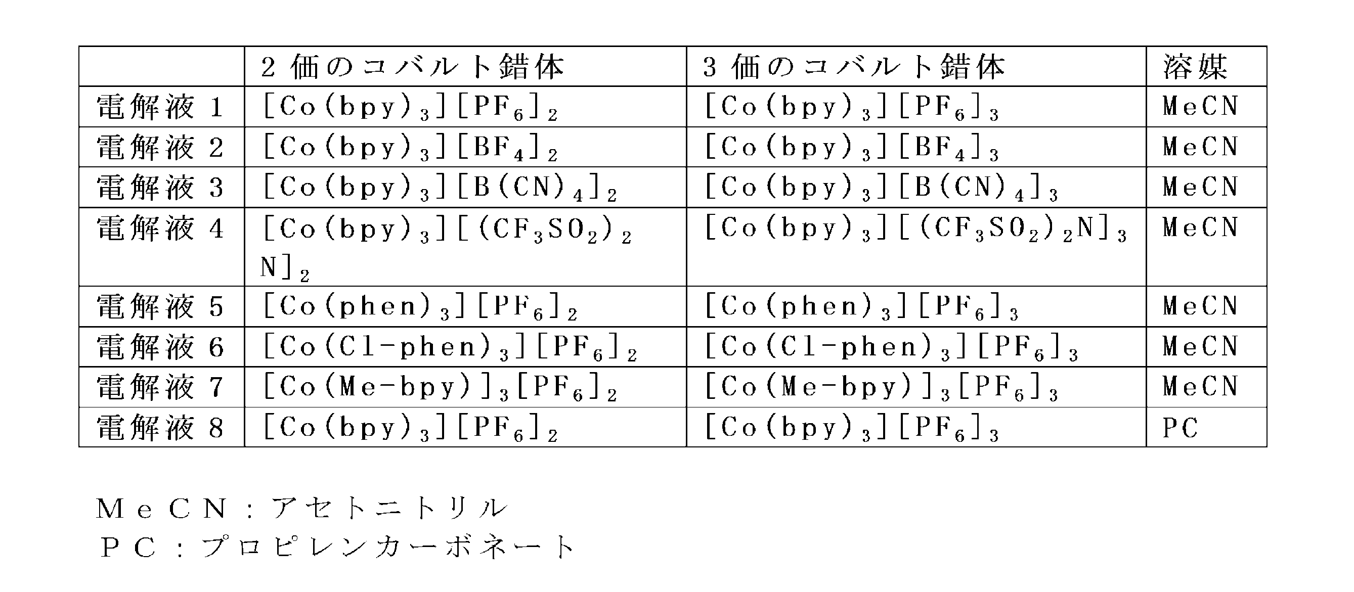
表2に記載の組成比で、2価のコバルト錯体(0.22mol/dm3)、3価のコバルト錯体(0.022mol/dm3)、過塩素酸リチウム(0.1mol/dm3)を、それぞれ所定の濃度になるように溶媒に混合したもの。 <Electrolytes 1-8>
In the composition ratio shown in Table 2, a divalent cobalt complex (0.22mol / dm 3), 3-valent cobalt complex (0.022mol / dm 3), lithium perchlorate (0.1mol / dm 3) , Mixed in a solvent so that each has a predetermined concentration.
アセトニトリルに対して、4-t-ブチルピリジン(0.5mol/dm3)、ヨウ化リチウム(0.5mol/dm3)、ヨウ素(0.05mol/dm3)を、それぞれ所定の濃度になるように混合したもの。 <Electrolytic solution 9>
4-t-butylpyridine (0.5 mol / dm 3 ), lithium iodide (0.5 mol / dm 3 ), and iodine (0.05 mol / dm 3 ) with respect to acetonitrile so as to have predetermined concentrations, respectively. Mixed with.
11 導電性基板
11A 基板
11B 導電層
12 金属酸化物半導体層
12A 緻密層
12B 多孔質層
13 色素
20 対向電極
21 導電性基板
22 導電層
30 電解質含有層
100 色素増感型太陽電池 DESCRIPTION OF SYMBOLS 10 Working electrode 11 Conductive
Claims (5)
- 色素が金属酸化物層に担持された色素担持金属酸化物電極を有する作用電極と対向電極が、電解質層を介して対向している色素増感型太陽電池であって、
色素が、シアニン色素を含有するものであり、
電解質層中の電解質が、コバルト系電解質を含有することを特徴とする色素増感型太陽電池。 A dye-sensitized solar cell in which a working electrode and a counter electrode having a dye-supported metal oxide electrode in which a dye is supported on a metal oxide layer are opposed to each other through an electrolyte layer,
The dye contains a cyanine dye,
A dye-sensitized solar cell, wherein the electrolyte in the electrolyte layer contains a cobalt-based electrolyte. - シアニン色素が、下記一般式(1)で表される化合物の少なくとも1種であることを特徴とする請求項1に記載の色素増感型太陽電池。

(式中、Aは下記の群Iの(a)~(m)から選ばれる基を表し、A' は下記の群IIの(a’)~(m’)から選ばれる基を表し、
Qは炭素原子数1~9のメチン鎖を構成し、鎖中に環構造を含んでもよい連結基を表し、該メチン鎖中の水素原子は水酸基、ハロゲン原子、シアノ基、-NRR’、アリール基、アリールアルキル基またはアルキル基で置換されていてもよく、該-NRR’、アリール基、アリールアルキル基およびアルキル基は更に水酸基、ハロゲン原子、シアノ基またはNRR’で置換されていてもよく、-O-、-S-、-CO-、-COO-、-OCO-、-SO2-、-NH-、-CONH-、-NHCO-、-N=CH-または-CH=CH-で中断されてもよく、
RおよびR’は、アリール基、アリールアルキル基またはアルキル基を表し、
Anq-はq価のアニオンを表し、qは1または2を表し、pは電荷を中性に保つ係数を表す。)

(式中、環Cおよび環C’は、ベンゼン環、ナフタレン環、フェナントレン環またはピリジン環を表し、
R1およびR1’は、水酸基、ハロゲン原子、ニトロ基、シアノ基、スルホン酸基、リン酸基、カルボン酸基、アミノ基、アミド基、フェロセニル基、炭素原子数6~30のアリール基、炭素原子数7~30のアリールアルキル基または炭素原子数1~8のアルキル基を表し、
該炭素原子数6~30のアリール基、炭素原子数7~30のアリールアルキル基および炭素原子数1~8のアルキル基は、水酸基、ハロゲン原子、ニトロ基、シアノ基、スルホン酸基、リン酸基、カルボン酸基、アミノ基、アミド基またはフェロセニル基で置換されていてもよく、-O-、-S-、-CO-、-COO-、-OCO-、-SO2-、-NH-、-CONH-、-NHCO-、-N=CH-または-CH=CH-で中断されていてもよく、
R2~R9およびR2’~R9’は、R1およびR1’と同様の基または水素原子を表し、
XおよびX’は、酸素原子、硫黄原子、セレン原子、-CR51R52-、炭素原子数3~6のシクロアルカン-1,1-ジイル基、-NH-またはNY2-を表し、
R51およびR52は、R1およびR1’と同様の基または水素原子を表し、
Y、Y’およびY2は、水素原子、または水酸基、ハロゲン原子、シアノ基、カルボン酸基、アミノ基、アミド基、フェロセニル基、スルホン酸基、リン酸基、-SiR6R7R8若しくはニトロ基で置換されてもよい炭素原子数1~20のアルキル基、炭素原子数6~30のアリール基若しくは炭素原子数7~30のアリールアルキル基を表し、
該Y、Y’およびY2中のアルキル基、アリール基およびアリールアルキル基中のメチレン基は、-O-、-S-、-CO-、-COO-、-OCO-、-SO2-、-NH-、-CONH-、-NHCO-、-N=CH-または-CH=CH-で中断されていてもよく、
rおよびr’は、0または(a)~(e)、(g)~(j)、(l)、(m)、(a’)~(e’)、(g’)~(j’)、(l’)および(m’)において置換可能な数を表す。) The dye-sensitized solar cell according to claim 1, wherein the cyanine dye is at least one compound represented by the following general formula (1).
(Wherein A represents a group selected from groups (a) to (m) of the following group I, A ′ represents a group selected from groups (a ′) to (m ′) of the following group II;
Q represents a methine chain having 1 to 9 carbon atoms, and represents a linking group that may contain a ring structure in the chain, and the hydrogen atom in the methine chain is a hydroxyl group, a halogen atom, a cyano group, —NRR ′, aryl Group, an arylalkyl group or an alkyl group, and the —NRR ′, aryl group, arylalkyl group and alkyl group may be further substituted with a hydroxyl group, a halogen atom, a cyano group or NRR ′; Interrupted by —O—, —S—, —CO—, —COO—, —OCO—, —SO 2 —, —NH—, —CONH—, —NHCO—, —N═CH— or —CH═CH—. May be,
R and R ′ represent an aryl group, an arylalkyl group or an alkyl group,
An q− represents a q-valent anion, q represents 1 or 2, and p represents a coefficient for keeping the charge neutral. )
(Wherein, ring C and ring C ′ represent a benzene ring, a naphthalene ring, a phenanthrene ring or a pyridine ring,
R 1 and R 1 ′ are a hydroxyl group, a halogen atom, a nitro group, a cyano group, a sulfonic acid group, a phosphoric acid group, a carboxylic acid group, an amino group, an amide group, a ferrocenyl group, an aryl group having 6 to 30 carbon atoms, An arylalkyl group having 7 to 30 carbon atoms or an alkyl group having 1 to 8 carbon atoms;
The aryl group having 6 to 30 carbon atoms, the arylalkyl group having 7 to 30 carbon atoms and the alkyl group having 1 to 8 carbon atoms are a hydroxyl group, a halogen atom, a nitro group, a cyano group, a sulfonic acid group, a phosphoric acid group. Group, carboxylic acid group, amino group, amide group or ferrocenyl group, and may be substituted with —O—, —S—, —CO—, —COO—, —OCO—, —SO 2 —, —NH—. , —CONH—, —NHCO—, —N═CH— or —CH═CH—,
R 2 to R 9 and R 2 ′ to R 9 ′ represent the same group or hydrogen atom as R 1 and R 1 ′,
X and X ′ represent an oxygen atom, a sulfur atom, a selenium atom, —CR 51 R 52 —, a cycloalkane-1,1-diyl group having 3 to 6 carbon atoms, —NH— or NY 2 —,
R 51 and R 52 represent the same group or hydrogen atom as R 1 and R 1 ′,
Y, Y ′ and Y 2 are each a hydrogen atom, a hydroxyl group, a halogen atom, a cyano group, a carboxylic acid group, an amino group, an amide group, a ferrocenyl group, a sulfonic acid group, a phosphoric acid group, —SiR 6 R 7 R 8 or An alkyl group having 1 to 20 carbon atoms, an aryl group having 6 to 30 carbon atoms, or an arylalkyl group having 7 to 30 carbon atoms which may be substituted with a nitro group;
The alkyl group, the aryl group and the methylene group in the arylalkyl group in Y, Y ′ and Y 2 are —O—, —S—, —CO—, —COO—, —OCO—, —SO 2 —, May be interrupted by —NH—, —CONH—, —NHCO—, —N═CH— or —CH═CH—,
r and r ′ are 0 or (a) to (e), (g) to (j), (l), (m), (a ′) to (e ′), (g ′) to (j ′) ), (L ′) and (m ′) represent the number that can be substituted. ) - 上記一般式(1)で表される化合物が、上記Qが、下記(Q-1)~(Q-11)の何れかで表わされる化合物である請求項2に記載の色素増感型太陽電池。

(式中、R14、R15、R16、R17、R18、R19およびZ’は、各々独立に、水素原子、水酸基、ハロゲン原子、シアノ基、-NRR’、アリール基、アリールアルキル基またはアルキル基を表し、該-NRR’、アリール基、アリールアルキル基およびアルキル基は、水酸基、ハロゲン原子、シアノ基またはNRR’で置換されていてもよく、-O-、-S-、-CO-、-COO-、-OCO-、-SO2-、-NH-、-CONH-、-NHCO-、-N=CH-または-CH=CH-で中断されていてもよく、
RおよびR’は、アリール基、アリールアルキル基またはアルキル基を表す。) The dye-sensitized solar cell according to claim 2, wherein the compound represented by the general formula (1) is a compound in which the Q is represented by any of the following (Q-1) to (Q-11): .
Wherein R 14 , R 15 , R 16 , R 17 , R 18 , R 19 and Z ′ are each independently a hydrogen atom, a hydroxyl group, a halogen atom, a cyano group, —NRR ′, an aryl group, an arylalkyl The —NRR ′, aryl group, arylalkyl group and alkyl group may be substituted with a hydroxyl group, a halogen atom, a cyano group or NRR ′, and —O—, —S—, — CO—, —COO—, —OCO—, —SO 2 —, —NH—, —CONH—, —NHCO—, —N═CH— or —CH═CH— may be interrupted,
R and R ′ represent an aryl group, an arylalkyl group or an alkyl group. ) - 上記一般式(1)で表される化合物が、上記(a)~(e)、(h)~(m)、(a’)~(e’)または(h’)~(m’)から選ばれる基を1または2有する化合物であることを特徴とする請求項2又は3に記載の色素増感型太陽電池。 The compound represented by the general formula (1) is obtained from the above (a) to (e), (h) to (m), (a ′) to (e ′) or (h ′) to (m ′). The dye-sensitized solar cell according to claim 2 or 3, wherein the dye-sensitized solar cell is a compound having 1 or 2 groups selected.
- 上記一般式(1)で表される化合物が、Aが上記(a)または(h)~(k)から選ばれる基であり、
A’が上記(a’)または(h’)~(k’)から選ばれる基であり、
Qが炭素原子数1、3、5または7のメチン鎖を構成し、鎖中に環構造を含んでもよい連結基を表し、該メチン鎖中の水素原子は、水酸基、ハロゲン原子、シアノ基、-NRR’、アリール基、アリールアルキル基またはアルキル基で置換されていてもよく、該-NRR’、アリール基、アリールアルキル基およびアルキル基は更に水酸基、ハロゲン原子、シアノ基またはNRR’で置換されていてもよく、-O-、-S-、-CO-、-COO-、-OCO-、-SO2-、-NH-、-CONH-、-NHCO-、-N=CH-または-CH=CH-で中断されてもよく、RおよびR’は、アリール基、アリールアルキル基またはアルキル基を表す基である化合物であることを特徴とする請求項2~4のいずれか1項に記載の色素増感型太陽電池。 In the compound represented by the general formula (1), A is a group selected from the above (a) or (h) to (k),
A ′ is a group selected from the above (a ′) or (h ′) to (k ′),
Q represents a methine chain having 1, 3, 5 or 7 carbon atoms, and represents a linking group that may contain a ring structure in the chain, and the hydrogen atom in the methine chain includes a hydroxyl group, a halogen atom, a cyano group, -NRR ', an aryl group, an arylalkyl group or an alkyl group may be substituted, and the -NRR', aryl group, arylalkyl group and alkyl group may be further substituted with a hydroxyl group, a halogen atom, a cyano group or NRR '. -O-, -S-, -CO-, -COO-, -OCO-, -SO 2- , -NH-, -CONH-, -NHCO-, -N = CH- or -CH The compound according to any one of claims 2 to 4, which may be interrupted by = CH-, wherein R and R 'are an aryl group, an arylalkyl group or a group representing an alkyl group. Dye-sensitized solar power pond.
Priority Applications (5)
| Application Number | Priority Date | Filing Date | Title |
|---|---|---|---|
| US14/899,129 US9881745B2 (en) | 2013-08-29 | 2014-08-12 | Dye sensitized solar cell |
| CN201480035582.5A CN105340037B (en) | 2013-08-29 | 2014-08-12 | dye-sensitized solar cell |
| JP2015534132A JP6391577B2 (en) | 2013-08-29 | 2014-08-12 | Dye-sensitized solar cell |
| EP14839829.0A EP3041008A4 (en) | 2013-08-29 | 2014-08-12 | Dye-sensitized solar cell |
| KR1020157036230A KR20160048039A (en) | 2013-08-29 | 2014-08-12 | Dye-sensitized solar cell |
Applications Claiming Priority (2)
| Application Number | Priority Date | Filing Date | Title |
|---|---|---|---|
| JP2013177768 | 2013-08-29 | ||
| JP2013-177768 | 2013-08-29 |
Publications (1)
| Publication Number | Publication Date |
|---|---|
| WO2015029771A1 true WO2015029771A1 (en) | 2015-03-05 |
Family
ID=52586340
Family Applications (1)
| Application Number | Title | Priority Date | Filing Date |
|---|---|---|---|
| PCT/JP2014/071285 WO2015029771A1 (en) | 2013-08-29 | 2014-08-12 | Dye-sensitized solar cell |
Country Status (7)
| Country | Link |
|---|---|
| US (1) | US9881745B2 (en) |
| EP (1) | EP3041008A4 (en) |
| JP (1) | JP6391577B2 (en) |
| KR (1) | KR20160048039A (en) |
| CN (1) | CN105340037B (en) |
| TW (1) | TWI623125B (en) |
| WO (1) | WO2015029771A1 (en) |
Families Citing this family (3)
| Publication number | Priority date | Publication date | Assignee | Title |
|---|---|---|---|---|
| US10653183B2 (en) * | 2016-11-18 | 2020-05-19 | Rai Strategic Holdings, Inc. | Power source for an aerosol delivery device |
| CN111192761A (en) * | 2019-12-27 | 2020-05-22 | 中北大学 | Long-time-state semitransparent flexible dye-sensitized solar cell and preparation method thereof |
| CN116715976A (en) * | 2023-05-18 | 2023-09-08 | 大连理工大学 | Chiral carbon-containing pentamethine cyanine dye, and preparation method and application thereof |
Citations (26)
| Publication number | Priority date | Publication date | Assignee | Title |
|---|---|---|---|---|
| JPH08253705A (en) | 1995-03-06 | 1996-10-01 | Minnesota Mining & Mfg Co <3M> | Organic soluble cationic dye with fluorinated alkylsulfonyl counter ion |
| JPH10235999A (en) | 1997-02-21 | 1998-09-08 | Fuji Photo Film Co Ltd | Optical information recording medium |
| JPH10337959A (en) | 1997-04-10 | 1998-12-22 | Fuji Electric Co Ltd | Optical recording medium |
| JPH11102088A (en) | 1997-09-26 | 1999-04-13 | Orient Chem Ind Ltd | Electric charge controlling agent and toner for developing electrostatic charge image |
| JP2000108510A (en) | 1998-10-01 | 2000-04-18 | Asahi Denka Kogyo Kk | Optical recording material |
| JP2000168223A (en) | 1998-12-02 | 2000-06-20 | Nishikawa:Kk | Method for printing latent information on medium |
| JP2001209969A (en) | 2000-01-26 | 2001-08-03 | Asahi Denka Kogyo Kk | Optical recording material |
| JP2001322354A (en) | 2000-05-16 | 2001-11-20 | Asahi Denka Kogyo Kk | Optical recording material |
| JP2003168493A (en) | 2001-11-30 | 2003-06-13 | Tdk Corp | Dye sensitizing solar cell |
| JP2003331936A (en) | 2002-05-13 | 2003-11-21 | National Institute Of Advanced Industrial & Technology | Photoelectric conversion element using electrolyte containing pyridine and/or pyridine-based compound, and dye sensitized solar cell using the same |
| JP2004503379A (en) | 2000-07-13 | 2004-02-05 | ロディア・シミ | Compositions and compounds based on acidic salts having a metal and a sulfonyl group bonded to a perhalogenated carbon, and their use as Lewis acids |
| JP2005093313A (en) | 2003-09-19 | 2005-04-07 | Toyo Ink Mfg Co Ltd | Electrolyte composition for dye-sensitized photoelectric conversion element, and photoelectric conversion element using it |
| JP2005336150A (en) | 2003-11-10 | 2005-12-08 | Nippon Kayaku Co Ltd | Diimmonium compound and use of the same |
| JP2005353289A (en) | 2004-06-08 | 2005-12-22 | Asahi Kasei Corp | Dye-sensitized solar cell |
| WO2006028006A1 (en) | 2004-09-06 | 2006-03-16 | Nippon Kayaku Kabushiki Kaisha | Diimmonium compound and use thereof |
| JP2006248180A (en) | 2005-03-14 | 2006-09-21 | Mitsui Chemicals Inc | Trimethine-based compound and optical recording medium using this |
| JP2006297907A (en) | 2005-02-28 | 2006-11-02 | Fuji Photo Film Co Ltd | Original lithographic printing plate, method for manufacturing original lithographic printing plate and lithographic printing method |
| US20080236663A1 (en) | 2007-03-30 | 2008-10-02 | Tdk Corporation | Photoelectric conversion device |
| JP2008274230A (en) | 2007-03-30 | 2008-11-13 | Adeka Corp | Cyanine compound and optical filter and optical recording material using the compound |
| WO2010038589A1 (en) | 2008-09-30 | 2010-04-08 | Tdk株式会社 | Dye for photoelectric conversion element and photoelectric conversion element |
| JP2010157373A (en) | 2008-12-26 | 2010-07-15 | Tdk Corp | Pigment for photoelectric conversion element and photoelectric conversion element |
| WO2012133488A1 (en) * | 2011-03-28 | 2012-10-04 | 積水化学工業株式会社 | Photoelectrode, and dye-sensitized solar cell provided with photoelectrode |
| JP2013025949A (en) * | 2011-07-19 | 2013-02-04 | Sumitomo Metal Mining Co Ltd | Dye-sensitized solar cell |
| JP2013077449A (en) | 2011-09-30 | 2013-04-25 | Fujifilm Corp | Photoelectric conversion element and photoelectrochemical cell using the same |
| JP2014078472A (en) * | 2012-10-12 | 2014-05-01 | Nec Corp | Photoelectric conversion element |
| JP2014127252A (en) * | 2012-12-25 | 2014-07-07 | Nec Corp | Photoelectric conversion element and manufacturing method thereof |
Family Cites Families (1)
| Publication number | Priority date | Publication date | Assignee | Title |
|---|---|---|---|---|
| US9779879B2 (en) | 2011-02-25 | 2017-10-03 | Ecole Polytechnique Federale De Lausanne (Epfl) | Redox couple for electrochemical and optoelectronic devices |
-
2014
- 2014-08-12 CN CN201480035582.5A patent/CN105340037B/en not_active Expired - Fee Related
- 2014-08-12 EP EP14839829.0A patent/EP3041008A4/en not_active Withdrawn
- 2014-08-12 KR KR1020157036230A patent/KR20160048039A/en not_active Application Discontinuation
- 2014-08-12 US US14/899,129 patent/US9881745B2/en not_active Expired - Fee Related
- 2014-08-12 JP JP2015534132A patent/JP6391577B2/en not_active Expired - Fee Related
- 2014-08-12 WO PCT/JP2014/071285 patent/WO2015029771A1/en active Application Filing
- 2014-08-18 TW TW103128337A patent/TWI623125B/en not_active IP Right Cessation
Patent Citations (26)
| Publication number | Priority date | Publication date | Assignee | Title |
|---|---|---|---|---|
| JPH08253705A (en) | 1995-03-06 | 1996-10-01 | Minnesota Mining & Mfg Co <3M> | Organic soluble cationic dye with fluorinated alkylsulfonyl counter ion |
| JPH10235999A (en) | 1997-02-21 | 1998-09-08 | Fuji Photo Film Co Ltd | Optical information recording medium |
| JPH10337959A (en) | 1997-04-10 | 1998-12-22 | Fuji Electric Co Ltd | Optical recording medium |
| JPH11102088A (en) | 1997-09-26 | 1999-04-13 | Orient Chem Ind Ltd | Electric charge controlling agent and toner for developing electrostatic charge image |
| JP2000108510A (en) | 1998-10-01 | 2000-04-18 | Asahi Denka Kogyo Kk | Optical recording material |
| JP2000168223A (en) | 1998-12-02 | 2000-06-20 | Nishikawa:Kk | Method for printing latent information on medium |
| JP2001209969A (en) | 2000-01-26 | 2001-08-03 | Asahi Denka Kogyo Kk | Optical recording material |
| JP2001322354A (en) | 2000-05-16 | 2001-11-20 | Asahi Denka Kogyo Kk | Optical recording material |
| JP2004503379A (en) | 2000-07-13 | 2004-02-05 | ロディア・シミ | Compositions and compounds based on acidic salts having a metal and a sulfonyl group bonded to a perhalogenated carbon, and their use as Lewis acids |
| JP2003168493A (en) | 2001-11-30 | 2003-06-13 | Tdk Corp | Dye sensitizing solar cell |
| JP2003331936A (en) | 2002-05-13 | 2003-11-21 | National Institute Of Advanced Industrial & Technology | Photoelectric conversion element using electrolyte containing pyridine and/or pyridine-based compound, and dye sensitized solar cell using the same |
| JP2005093313A (en) | 2003-09-19 | 2005-04-07 | Toyo Ink Mfg Co Ltd | Electrolyte composition for dye-sensitized photoelectric conversion element, and photoelectric conversion element using it |
| JP2005336150A (en) | 2003-11-10 | 2005-12-08 | Nippon Kayaku Co Ltd | Diimmonium compound and use of the same |
| JP2005353289A (en) | 2004-06-08 | 2005-12-22 | Asahi Kasei Corp | Dye-sensitized solar cell |
| WO2006028006A1 (en) | 2004-09-06 | 2006-03-16 | Nippon Kayaku Kabushiki Kaisha | Diimmonium compound and use thereof |
| JP2006297907A (en) | 2005-02-28 | 2006-11-02 | Fuji Photo Film Co Ltd | Original lithographic printing plate, method for manufacturing original lithographic printing plate and lithographic printing method |
| JP2006248180A (en) | 2005-03-14 | 2006-09-21 | Mitsui Chemicals Inc | Trimethine-based compound and optical recording medium using this |
| US20080236663A1 (en) | 2007-03-30 | 2008-10-02 | Tdk Corporation | Photoelectric conversion device |
| JP2008274230A (en) | 2007-03-30 | 2008-11-13 | Adeka Corp | Cyanine compound and optical filter and optical recording material using the compound |
| WO2010038589A1 (en) | 2008-09-30 | 2010-04-08 | Tdk株式会社 | Dye for photoelectric conversion element and photoelectric conversion element |
| JP2010157373A (en) | 2008-12-26 | 2010-07-15 | Tdk Corp | Pigment for photoelectric conversion element and photoelectric conversion element |
| WO2012133488A1 (en) * | 2011-03-28 | 2012-10-04 | 積水化学工業株式会社 | Photoelectrode, and dye-sensitized solar cell provided with photoelectrode |
| JP2013025949A (en) * | 2011-07-19 | 2013-02-04 | Sumitomo Metal Mining Co Ltd | Dye-sensitized solar cell |
| JP2013077449A (en) | 2011-09-30 | 2013-04-25 | Fujifilm Corp | Photoelectric conversion element and photoelectrochemical cell using the same |
| JP2014078472A (en) * | 2012-10-12 | 2014-05-01 | Nec Corp | Photoelectric conversion element |
| JP2014127252A (en) * | 2012-12-25 | 2014-07-07 | Nec Corp | Photoelectric conversion element and manufacturing method thereof |
Non-Patent Citations (3)
| Title |
|---|
| J. M. CHEM. SOC., vol. 124, 2001, pages 11215 - 11222 |
| J. PHYS. CHEM. B: APPL., vol. 105, 2001, pages 6867 - 6873 |
| See also references of EP3041008A4 |
Also Published As
| Publication number | Publication date |
|---|---|
| CN105340037A (en) | 2016-02-17 |
| TW201513437A (en) | 2015-04-01 |
| CN105340037B (en) | 2018-04-27 |
| EP3041008A4 (en) | 2017-04-19 |
| US20160148758A1 (en) | 2016-05-26 |
| TWI623125B (en) | 2018-05-01 |
| EP3041008A1 (en) | 2016-07-06 |
| KR20160048039A (en) | 2016-05-03 |
| JP6391577B2 (en) | 2018-09-19 |
| US9881745B2 (en) | 2018-01-30 |
| JPWO2015029771A1 (en) | 2017-03-02 |
Similar Documents
| Publication | Publication Date | Title |
|---|---|---|
| JP5925541B2 (en) | Metal complex dye for photoelectric conversion element, photoelectric conversion element, dye-sensitized solar cell, dye-adsorbing composition liquid for dye-sensitized solar cell, semiconductor electrode for dye-sensitized solar cell, and method for producing dye-sensitized solar cell | |
| JP5250412B2 (en) | Dye for photoelectric conversion element and photoelectric conversion element | |
| JP5442625B2 (en) | Dye for photoelectric conversion element and photoelectric conversion element | |
| JP6391577B2 (en) | Dye-sensitized solar cell | |
| KR101530454B1 (en) | Photoelectric conversion element, pigment for photoelectric conversion element and compound | |
| WO2015178257A1 (en) | Loading method, loaded body and photoelectric conversion element | |
| JP6113713B2 (en) | Novel compound and carrier carrying the novel compound | |
| JP5914462B2 (en) | Novel compound and photoelectric conversion element | |
| JP5412955B2 (en) | Electrode and photoelectric conversion element | |
| US10141118B2 (en) | Carrier system and photoelectric conversion device | |
| TW201638234A (en) | Photoelectric conversion element, dye-sensitized solar cell, ruthenium complex dye, and dye solution | |
| JP2016219653A (en) | Support material and photoelectric conversion element |
Legal Events
| Date | Code | Title | Description |
|---|---|---|---|
| WWE | Wipo information: entry into national phase |
Ref document number: 201480035582.5 Country of ref document: CN |
|
| 121 | Ep: the epo has been informed by wipo that ep was designated in this application |
Ref document number: 14839829 Country of ref document: EP Kind code of ref document: A1 |
|
| ENP | Entry into the national phase |
Ref document number: 2015534132 Country of ref document: JP Kind code of ref document: A |
|
| REEP | Request for entry into the european phase |
Ref document number: 2014839829 Country of ref document: EP |
|
| WWE | Wipo information: entry into national phase |
Ref document number: 14899129 Country of ref document: US Ref document number: 2014839829 Country of ref document: EP |
|
| ENP | Entry into the national phase |
Ref document number: 20157036230 Country of ref document: KR Kind code of ref document: A |
|
| NENP | Non-entry into the national phase |
Ref country code: DE |