WO2015029480A1 - 過電流検出装置及び過電流検出方法 - Google Patents
過電流検出装置及び過電流検出方法 Download PDFInfo
- Publication number
- WO2015029480A1 WO2015029480A1 PCT/JP2014/057094 JP2014057094W WO2015029480A1 WO 2015029480 A1 WO2015029480 A1 WO 2015029480A1 JP 2014057094 W JP2014057094 W JP 2014057094W WO 2015029480 A1 WO2015029480 A1 WO 2015029480A1
- Authority
- WO
- WIPO (PCT)
- Prior art keywords
- current value
- power supply
- supply line
- overcurrent
- inverter circuit
- Prior art date
- Legal status (The legal status is an assumption and is not a legal conclusion. Google has not performed a legal analysis and makes no representation as to the accuracy of the status listed.)
- Ceased
Links
Images


Classifications
-
- H—ELECTRICITY
- H02—GENERATION; CONVERSION OR DISTRIBUTION OF ELECTRIC POWER
- H02P—CONTROL OR REGULATION OF ELECTRIC MOTORS, ELECTRIC GENERATORS OR DYNAMO-ELECTRIC CONVERTERS; CONTROLLING TRANSFORMERS, REACTORS OR CHOKE COILS
- H02P29/00—Arrangements for regulating or controlling electric motors, appropriate for both AC and DC motors
- H02P29/02—Providing protection against overload without automatic interruption of supply
- H02P29/024—Detecting a fault condition, e.g. short circuit, locked rotor, open circuit or loss of load
- H02P29/027—Detecting a fault condition, e.g. short circuit, locked rotor, open circuit or loss of load the fault being an over-current
-
- G—PHYSICS
- G01—MEASURING; TESTING
- G01R—MEASURING ELECTRIC VARIABLES; MEASURING MAGNETIC VARIABLES
- G01R19/00—Arrangements for measuring currents or voltages or for indicating presence or sign thereof
- G01R19/165—Indicating that current or voltage is either above or below a predetermined value or within or outside a predetermined range of values
-
- G—PHYSICS
- G01—MEASURING; TESTING
- G01R—MEASURING ELECTRIC VARIABLES; MEASURING MAGNETIC VARIABLES
- G01R31/00—Arrangements for testing electric properties; Arrangements for locating electric faults; Arrangements for electrical testing characterised by what is being tested not provided for elsewhere
- G01R31/34—Testing dynamo-electric machines
- G01R31/343—Testing dynamo-electric machines in operation
-
- H—ELECTRICITY
- H02—GENERATION; CONVERSION OR DISTRIBUTION OF ELECTRIC POWER
- H02H—EMERGENCY PROTECTIVE CIRCUIT ARRANGEMENTS
- H02H7/00—Emergency protective circuit arrangements specially adapted for specific types of electric machines or apparatus or for sectionalised protection of cable or line systems, and effecting automatic switching in the event of an undesired change from normal working conditions
- H02H7/10—Emergency protective circuit arrangements specially adapted for specific types of electric machines or apparatus or for sectionalised protection of cable or line systems, and effecting automatic switching in the event of an undesired change from normal working conditions for converters; for rectifiers
- H02H7/12—Emergency protective circuit arrangements specially adapted for specific types of electric machines or apparatus or for sectionalised protection of cable or line systems, and effecting automatic switching in the event of an undesired change from normal working conditions for converters; for rectifiers for static converters or rectifiers
- H02H7/122—Emergency protective circuit arrangements specially adapted for specific types of electric machines or apparatus or for sectionalised protection of cable or line systems, and effecting automatic switching in the event of an undesired change from normal working conditions for converters; for rectifiers for static converters or rectifiers for inverters, i.e. DC/AC converters
- H02H7/1222—Emergency protective circuit arrangements specially adapted for specific types of electric machines or apparatus or for sectionalised protection of cable or line systems, and effecting automatic switching in the event of an undesired change from normal working conditions for converters; for rectifiers for static converters or rectifiers for inverters, i.e. DC/AC converters responsive to abnormalities in the input circuit, e.g. transients in the DC input
-
- G—PHYSICS
- G01—MEASURING; TESTING
- G01R—MEASURING ELECTRIC VARIABLES; MEASURING MAGNETIC VARIABLES
- G01R31/00—Arrangements for testing electric properties; Arrangements for locating electric faults; Arrangements for electrical testing characterised by what is being tested not provided for elsewhere
- G01R31/40—Testing power supplies
- G01R31/42—AC power supplies
-
- H—ELECTRICITY
- H02—GENERATION; CONVERSION OR DISTRIBUTION OF ELECTRIC POWER
- H02M—APPARATUS FOR CONVERSION BETWEEN AC AND AC, BETWEEN AC AND DC, OR BETWEEN DC AND DC, AND FOR USE WITH MAINS OR SIMILAR POWER SUPPLY SYSTEMS; CONVERSION OF DC OR AC INPUT POWER INTO SURGE OUTPUT POWER; CONTROL OR REGULATION THEREOF
- H02M1/00—Details of apparatus for conversion
- H02M1/0003—Details of control, feedback or regulation circuits
- H02M1/0009—Devices or circuits for detecting current in a converter
Definitions
- the present invention relates to an overcurrent detection device and an overcurrent detection method for detecting an overcurrent upstream of an inverter circuit in an electric motor drive control device.
- Patent Document 1 describes a device using a current detection resistor.
- current detection resistors are provided upstream and downstream of the inverter circuit, respectively, and an overcurrent due to a short circuit of each path or a ground fault in the inverter circuit is detected by a change in voltage at both ends of these current detection resistors.
- the present invention has been made in view of the circumstances as described above, and an object of the present invention is to detect an overcurrent without providing a shunt resistor upstream of the inverter circuit and to reduce the size of the circuit board.
- An apparatus and an overcurrent detection method are provided.
- the current value flowing through the power supply line is calculated from the phase current supplied to the electric motor and the power supply voltage of the inverter circuit, and the drive connected to the power supply line is calculated.
- the overcurrent is detected based on the current value obtained from the voltage drop value by the electronic component for the control device and the current value flowing through the power supply line.
- the shunt resistor upstream of the inverter circuit can be made unnecessary. Variations in resistance values and changes in characteristics of electronic components are calculated by calculating the current value flowing through the power supply line from the phase current supplied to the electric motor and the power supply voltage of the inverter circuit, and obtaining the current value from the current value and the drop voltage value. It can be suppressed by detecting an overcurrent based on the value. As a result, the mounting area and the wiring area can be reduced, and the circuit board can be reduced in size.
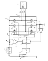
- FIG. 1 is an overcurrent detection device according to a first embodiment of the present invention, and is a circuit diagram of a drive control device for an electric motor.
- 2 is a flowchart showing an overcurrent detection operation in the circuit shown in FIG. 1.
- the overcurrent detection apparatus which concerns on the 2nd Embodiment of this invention is shown, and it is a circuit diagram of the drive control apparatus of an electric motor.
- the drive control device for the electric motor shown in FIG. 1 includes an inverter circuit 2 that drives the electric motor 1, an inverter drive IC 3 that controls on / off of each MOSFET 21 to 26 of the inverter circuit 2, a CPU 4, and an FS (fail safe) relay 5. , A noise removing coil (inductor) 6, a smoothing capacitor 7, a DC power source 8, and the like.
- the overcurrent detection device also includes an operational amplifier 9 for detecting a drop voltage, an I / F (interface) circuit 10 for inputting the power supply voltage of the DC power supply 8 to the CPU 4, a phase current detection resistor 11, an operational amplifier 12, and the like. ing.
- the CPU 4 detects the voltage drop by the FS relay 5 detected by the operational amplifier 9, the voltage of the DC power supply 8 input via the I / F circuit 10, and the both ends of the phase current detection resistor 11 detected by the operational amplifier 12. Based on the potential difference, calculation and determination for detecting an overcurrent are performed.
- the inverter circuit 2 has a three-phase bridge circuit configuration including three sets of semiconductor elements that drive the U phase, the V phase, and the W phase of the electric motor 1 for each phase via the drive lines 2U, 2V, and 2W. Yes.
- each semiconductor element is composed of N-channel MOSFETs 21-26.
- MOSFETs 21 and 24 a drain-source current path is connected in series between one end of the power supply line 20 and the phase current detection resistor 11, and one end of the drive line 2U is connected to a common connection point.
- MOSFETs 22 and 25 a drain-source current path is connected in series between one end of the power supply line 20 and the phase current detection resistor 11, and one end of the drive line 2V is connected to a common connection point.
- a drain-source current path is connected in series between one end of the power supply line 20 and the phase current detection resistor 11, and one end of the drive line 2W is connected to a common connection point.
- the other end of the phase current detection resistor 11 is connected to a ground point (ground line).
- the diodes connected in the forward direction between the sources and drains of the MOSFETs 21 to 26 are parasitic diodes of the MOSFETs 21 to 26.
- a smoothing capacitor 7 is connected between the power line 20 upstream of the inverter circuit 2 and one end of the phase current detection resistor 11. Power is supplied to the power supply line 20 from the positive electrode of the DC power supply 8 via the FS relay 5 and the coil 6 which are electronic components for the drive control device.
- the first and second input terminals of the operational amplifier 9 are connected to both ends of the FS relay 5, and the potential difference, in other words, the drop voltage value is supplied to the CPU 4 from the output terminal. Further, the positive voltage of the DC power supply 8 is input to the CPU 4 via the I / F circuit 10 and the power supply voltage is measured.
- the first and second input terminals of the operational amplifier 12 are connected to both ends of the phase current detection resistor 11, and the potential difference is supplied from the output terminal to the CPU 4.
- the CPU 4 supplies a control signal to the inverter driving IC 3 according to the program.
- the inverter driving IC 3 supplies driving signals to the gates of the MOSFETs 21 to 26 in the inverter circuit 2 to turn them on / off.
- the CPU 4 controls the driving of the electric motor 1, for example, vector control.
- the CPU 4 calculates the phase current supplied from the inverter circuit 2 to the electric motor 1 based on the potential difference detected by the operational amplifier 12 and the power supply voltage supplied via the I / F circuit 10. Further, the CPU 4 calculates a current value flowing through the power supply line 20 from the phase current and the power supply voltage.
- the correction amount of the current value obtained from the voltage drop value by the FS relay 5 connected to the power supply line 20 upstream of the inverter circuit 2 is calculated based on the current value (estimated current value) flowing through the power supply line 20. Then, an overcurrent is detected using the current value calibrated with the calculated correction amount as a reference current value. The overcurrent detection operation is repeated at a predetermined timing, and the calibrated current value is updated with the current value at the previous detection timing.
- the overcurrent detection operation by the apparatus shown in FIG. 1, that is, the overcurrent detection method of the present invention will be described in detail with reference to the flowchart of FIG.
- the CPU 4 controls the inverter drive IC 3 to turn on / off the MOSFETs 21 to 26 and perform d-axis energization to the electric motor 1 (step S1) .
- the operational amplifier 12 detects a potential difference between both ends of the phase current detection resistor 11 when a d-axis current is passed through the electric motor 1. Further, the voltage of the DC power supply 8 is supplied to the CPU 4 by the I / F circuit 10 and the power supply voltage is measured (step S2).
- the phase current is calculated by the CPU 4 based on the potential difference and the power supply voltage, and the current value of the current flowing through the power supply line 20 of the inverter circuit 2 is calculated from the phase current and the power supply voltage (step S3).
- the value of the current flowing through the power supply line 20 of the inverter circuit 2 when a specified current is passed through the electric motor 1 is mapped to a storage device in the CPU 4 (may be outside the CPU 4) (step S4).
- the phase current is detected because the voltage drop value detected by the FS relay 5 does not know how much current is flowing through the FS relay 5. This is to estimate from the measured current value.
- the d-axis energization is an energization method that generates torque and does not generate rotational force, a substantially constant current flows. Therefore, the CPU 4 can store in advance, as calibration data, variations in resistance values of the FS relay 5 and errors due to changes in characteristics, such as changes in time, temperature changes, deterioration, and the like.
- step S5 When the drive control of the electric motor 1 is started (step S5), the operational amplifier 9 detects the potential difference (voltage drop value) at both ends of the FS relay 5 (electronic component) upstream of the inverter circuit 2 and supplies it to the CPU 4 (step S5). S6). In the next step S7, the CPU 4 calculates the current value of the power supply line 20 based on the voltage drop value detected in step S6, and calculates the correction amount using the current value of the power supply line 20 mapped in step S4. Then, the current value mapped in step S4 is updated with the calculated correction amount.
- step S8 the current value obtained from the drop voltage value is calibrated with the correction amount calculated by the CPU 4 in step S7.
- the current value obtained from the voltage drop value can be equal to or close to the current value (estimated current value) of the power supply line 20.
- the CPU 4 detects an overcurrent of the current flowing in the power supply line 20 (step S9). In the detection of overcurrent, for example, it is determined whether or not the current value of the power supply line 20 is greater than a calibrated current value or a preset current value by a predetermined value or more (step S10). To do. If the CPU 4 detects an overcurrent, the driving of the electric motor 1 is stopped (step S11) and the process ends. If not detected, the process returns to step S5 and the same operation is repeated.
- the drop voltage value is detected using the existing FS relay (electronic component) 5 for the drive control device installed upstream of the inverter circuit 2, and the downstream of the inverter circuit 2 is detected.
- the FS relay 5 can be used instead of the shunt resistor.
- an overcurrent can be detected based on the current value obtained from the voltage drop value of the FS relay 5 in the event of a ground fault upstream of the inverter circuit 2 without providing a shunt resistor upstream of the inverter circuit 2. .
- the current value when a specified current is passed through the power supply line 20 is mapped, and the current value flowing through the power supply line 20 obtained from the voltage drop of the FS relay 5 is calibrated. It is possible to suppress the influence due to variations in resistance value. Furthermore, since the current value of the power supply line 20 is updated to the current value after calibration, the influence of changes in characteristics of the FS relay 5, for example, changes in resistance values due to changes in the contact position of the relay contacts, and temperature changes, is suppressed. However, accuracy can be ensured even by using existing electronic components for the drive control device.
- the overcurrent detection device of the present invention does not require a shunt resistor upstream of the inverter circuit, so that the mounting area and the wiring area can be reduced.
- a vehicle ECU Engine Control Unit
- miniaturization of a circuit board is required for miniaturization.
- an overcurrent can be detected without using a shunt resistor. If it is applied to this drive control device, it is possible to reduce the size and cost of the ECU.
- a noise removing coil 6 is used as an electronic component upstream of the inverter circuit 2.
- the first and second input terminals of the operational amplifier 9 are connected to both ends of the noise removal coil 6 to detect a voltage drop value. Since the other basic configuration is the same as that of the first embodiment, the same parts as those in FIG. 1 are denoted by the same reference numerals, and detailed description thereof is omitted.
- the present invention is not limited to the first and second embodiments described above, and can be implemented with various modifications.
- d-axis energization is performed in step S1 of FIG. 2, it is possible to increase the accuracy by flowing currents having different current values and using straight line data connecting two current values as mapping data. More accurate mapping is also possible by passing currents of three or more different current values and associating the data with each other.
- the specified current value is mapped when the system is started, but it may be performed when the system is terminated.
- the electronic components for the drive control device are the power shut-off component (FS relay) and the noise removal coil.
- the present invention is not limited to these, and other existing electronic components may be used. Of course.
- SYMBOLS 1 Electric motor, 2 ... Inverter circuit, 5 ... Relay for FS (electronic component), 6 ... Coil for noise removal (electronic component), 8 ... DC power supply, 9, 12 ... Operational amplifier, 10 ... I / F circuit, 11 ... phase current detection resistor, 20 ... power supply line
Landscapes
- Engineering & Computer Science (AREA)
- Power Engineering (AREA)
- Physics & Mathematics (AREA)
- General Physics & Mathematics (AREA)
- Control Of Ac Motors In General (AREA)
- Inverter Devices (AREA)
- Measurement Of Current Or Voltage (AREA)
- Control Of Electric Motors In General (AREA)
Abstract
Description
[第1の実施形態]
図1に示す電動モータの駆動制御装置は、電動モータ1を駆動するインバータ回路2、インバータ回路2の各MOSFET21~26をオン/オフ制御するインバータ駆動IC3、CPU4、FS(フェイルセーフ)用リレー5、ノイズ除去用コイル(インダクタ)6、平滑コンデンサ7、及び直流電源8などを含んで構成されている。
MOSFET21,24は、電源ライン20と相電流検出抵抗11の一端間にドレイン・ソース間の電流通路が直列接続され、共通接続点に上記駆動ライン2Uの一端が接続される。MOSFET22,25は、電源ライン20と相電流検出抵抗11の一端間にドレイン・ソース間の電流通路が直列接続され、共通接続点に上記駆動ライン2Vの一端が接続される。また、MOSFET23,26は、電源ライン20と相電流検出抵抗11の一端間にドレイン・ソース間の電流通路が直列接続され、共通接続点に上記駆動ライン2Wの一端が接続される。相電流検出抵抗11の他端は、接地点(接地ライン)に接続されている。
尚、各MOSFET21~26のソース・ドレイン間に順方向に接続されているダイオードは、これらMOSFET21~26の寄生ダイオードである。
また、CPU4は、オペアンプ12で検出した電位差とI/F回路10を介して供給された電源電圧とに基づき、インバータ回路2から電動モータ1へ供給される相電流を算出する。更に、CPU4は、この相電流と電源電圧とから電源ライン20に流れる電流値を算出する。そして、インバータ回路2の上流の電源ライン20に接続されたFS用リレー5による降下電圧値から求めた電流値の補正量を、上記電源ライン20に流れる電流値(推定電流値)に基づいて算出し、算出した補正量で較正した電流値を基準の電流値として過電流を検出する。過電流の検出動作は、所定のタイミングで繰り返し、較正した電流値を前回の検出タイミングの電流値で更新する。
まず、電動モータの駆動制御装置であるシステムの起動時に、CPU4でインバータ駆動IC3を制御して、MOSFET21~26をオン/オフ制御し、電動モータ1に対してd軸通電を行う(ステップS1)。次に、電動モータ1にd軸電流を流したときの相電流検出抵抗11の両端の電位差をオペアンプ12で検出する。また、直流電源8の電圧をI/F回路10によりCPU4に供給して電源電圧を測定する(ステップS2)。
続いて、電位差と電源電圧とに基づいてCPU4で相電流を算出し、この相電流と電源電圧とからインバータ回路2の電源ライン20に流れる電流の電流値を算出する(ステップS3)。
そして、電動モータ1に規定の電流を流したときに、インバータ回路2の電源ライン20に流れる電流値をCPU4内(CPU4の外部でも良い)の記憶装置にマッピングする(ステップS4)。
次のステップS7では、CPU4により、ステップS6で検出した降下電圧値に基づき電源ライン20の電流値を算出し、ステップS4でマッピングした電源ライン20の電流値を用いて補正量を算出する。そして、算出した補正量によりステップS4でマッピングした電流値を更新する。
続いて、較正した電流値に基づき、CPU4により電源ライン20に流れている電流の過電流を検出する(ステップS9)。過電流の検出では、例えば電源ライン20の電流値が、較正した電流値、あるいは予め設定した電流値よりも、所定値以上大きいか否か判定し(ステップS10)、大きい場合に過電流と判定する。CPU4で過電流を検出した場合には、電動モータ1の駆動を停止(ステップS11)して終了し、検出しない場合には、ステップS5に戻って同様な動作を繰り返す。
また、システム起動時に、電源ライン20に規定の電流を流したときの電流値をマッピングし、FS用リレー5の降下電圧値から求めた、電源ライン20に流れる電流値を較正するので、電子部品の抵抗値のばらつきによる影響を抑制できる。
更に、電源ライン20の電流値を較正後の電流値に更新するので、FS用リレー5の特性の変化、例えばリレー接点の接触位置の変化による抵抗値の変化、及び温度変化などの影響を抑制し、駆動制御装置用の既設の電子部品を用いても精度を確保できる。
図3に示す第2の実施形態では、インバータ回路2の上流の電子部品として、ノイズ除去用コイル6を用いるものである。ノイズ除去用コイル6の両端にオペアンプ9の第1、第2入力端を接続し、降下電圧値を検出する。
他の基本的な構成は第1の実施形態と同様であるので、図1と同一部分に同じ符号を付して、その詳細な説明は省略する。
尚、ノイズ除去用コイル6は、リレーのようにオン/オフ動作で抵抗値が変化することはないので、予め抵抗値を測定して記憶装置に記憶しておき、検出した降下電圧値とこの抵抗値とに基づいて電源ライン20の電流値を算出しても良い。
例えば、図2のステップS1において、d軸通電を行う際、電流値の異なる電流を流し、二点の電流値を結ぶ直線のデータをマッピングデータとして使用することにより高精度化できる。3種類以上の異なる電流値の電流を流して各データを関連付けすることで、より高精度なマッピングも可能となる。
更に、駆動制御装置用の電子部品が、電源遮断部品(FS用リレー)とノイズ除去用コイルの場合について説明したが、これらに限られるものではなく、既設の他の電子部品を用いても良いのはもちろんである。
Claims (16)
- 電動モータの駆動制御装置におけるインバータ回路の上流の過電流を検出する過電流検出装置であって、
前記電動モータへ供給される相電流と前記インバータ回路の電源電圧とから電源ラインを流れる電流値を算出し、前記電源ラインに接続されている駆動制御装置用の電子部品による降下電圧値から求めた電流値と前記電源ラインを流れる電流値とに基づいて過電流を検出する、過電流検出装置。 - 前記電子部品による降下電圧値から求めた電流値を、前記電源ラインを流れる電流値で較正し、前記電源ラインを流れる電流値を較正後の電流値で更新する、請求項1記載の過電流検出装置。
- 前記電子部品が、直流電源と前記インバータ回路の電源ラインとの間に接続される、請求項1記載の過電流検出装置。
- 前記電子部品が、前記電動モータまたは前記駆動制御装置の故障時に、前記インバータ回路への電源の供給を停止する電源遮断部品、またはノイズ除去用コイルである、請求項3記載の過電流検出装置。
- 前記電子部品が、前記電動モータまたは前記駆動制御装置の故障時に、前記インバータ回路への電源の供給を停止する電源遮断部品、及び前記ノイズ除去用コイルを含み、前記電源遮断部品及び前記ノイズ除去用コイルは、直流電源と前記インバータ回路の電源ラインとの間に直列接続され、一方から前記降下電圧値が検出される請求項3記載の過電流検出装置。
- 前記インバータ回路は、駆動ラインを介して前記電動モータのU相、V相及びW相をそれぞれ相毎に駆動する3相ブリッジ回路構成である、請求項1記載の過電流検出装置。
- 前記インバータ回路を制御するインバータ駆動ICと、過電流を検出するための演算と判定を行い、前記インバータ駆動ICを制御するCPUとを更に備える、請求項1記載の過電流検出装置。
- 直流電源の電圧を前記CPUに供給するインターフェース回路と、前記電子部品による降下電圧値を検出し、前記CPUに供給する第1のオペアンプと、前記インバータ回路の下流と接地ライン間に接続された相電流検出抵抗と、前記相電流検出抵抗の両端の電位差を検出して前記CPUに供給する第2のオペアンプと、を更に備える、請求項7記載の過電流検出装置。
- 電動モータの駆動制御装置におけるインバータ回路の上流の過電流を検出する過電流検出方法であって、
前記インバータ回路における上流の駆動制御装置用の電子部品による降下電圧値を検出し、
前記電動モータへ供給される相電流、及び前記インバータ回路に印加される電源電圧を検出し、
前記相電流と前記電源電圧から電源ラインの電流値を推定し、
前記降下電圧値と前記推定電流値に基づいて補正量を算出し、
前記降下電圧から求められる電流値を前記補正量で補正し、
補正した前記電流値を基準にして過電流を検出する、過電流検出方法。 - 前記降下電圧値から求めた電流値を、前記電源ラインを流れる電流値で較正し、前記電源ラインを流れる電流値を較正後の電流値で更新するステップを更に備え、前記較正した電流値に基づき、前記電源ラインに流れている電流の過電流を検出する、請求項9記載の過電流検出方法。
- 前記降下電圧値から求めた電流値を、前記電源ラインを流れる電流値で較正し、前記電源ラインを流れる電流値を較正後の電流値で更新するステップは、以下のステップを含む請求項10記載の過電流検出方法、
前記電動モータに規定の電流を流し、
前記インバータ回路の前記電源ラインに流れる電流値を記憶装置にマッピングし、
前記マッピングした電源ラインの電流値を用いて補正量を算出し、
算出した補正量によりマッピングした電流値を更新する。 - 前記降下電圧値から求めた電流値を、前記電源ラインを流れる電流値で較正し、前記電源ラインを流れる電流値を較正後の電流値で更新するステップは、所定のタイミングで繰り返し、較正した電流値を前回の検出タイミングの電流値で更新する、請求項10記載の過電流検出方法。
- 前記補正した前記電流値を基準にして過電流を検出するステップは、前記補正した電流値が設定した電流値より大きいか否か判定し、前記設定した電流値より大きい場合に過電流と判定する、請求項9記載の過電流検出方法。
- 前記降下電圧値から求めた電流値を、前記電源ラインを流れる電流値で較正するステップと、前記電源ラインを流れる電流値を較正後の電流値で更新するステップとを更に備え、前記電源ラインの電流値が、前記較正した電流値よりも所定値以上大きいか否か判定し、所定値以上大きい場合に過電流と判定する、請求項9記載の過電流検出方法。
- 以下のステップを更に備える請求項9記載の過電流検出方法、
システム起動時またはシステム終了時に、前記電動モータに対してd軸通電を行い、
前記電動モータにd軸電流を流したときに、前記インバータ回路と接地ラインとの間に接続された相電流検出抵抗の両端の電位差を検出し、
前記インバータ回路に印加されている電源電圧を検出する。 - 以下のステップを更に備える請求項15記載の過電流検出方法、
前記インバータ回路の前記電源ラインに流れる電流値を記憶装置にマッピングする。
Priority Applications (3)
| Application Number | Priority Date | Filing Date | Title |
|---|---|---|---|
| CN201480001534.4A CN104603624A (zh) | 2013-08-30 | 2014-03-17 | 过电流检测装置以及过电流检测方法 |
| US14/424,081 US20160033559A1 (en) | 2013-08-30 | 2014-03-17 | Overcurrent detecting device and overcurrent detecting method |
| DE112014003924.1T DE112014003924T5 (de) | 2013-08-30 | 2014-03-17 | Überstromermittlungsvorrichtung und Überstromermittlungsverfahren |
Applications Claiming Priority (2)
| Application Number | Priority Date | Filing Date | Title |
|---|---|---|---|
| JP2013-180272 | 2013-08-30 | ||
| JP2013180272A JP6027509B2 (ja) | 2013-08-30 | 2013-08-30 | 過電流検出装置 |
Publications (1)
| Publication Number | Publication Date |
|---|---|
| WO2015029480A1 true WO2015029480A1 (ja) | 2015-03-05 |
Family
ID=52586063
Family Applications (1)
| Application Number | Title | Priority Date | Filing Date |
|---|---|---|---|
| PCT/JP2014/057094 Ceased WO2015029480A1 (ja) | 2013-08-30 | 2014-03-17 | 過電流検出装置及び過電流検出方法 |
Country Status (5)
| Country | Link |
|---|---|
| US (1) | US20160033559A1 (ja) |
| JP (1) | JP6027509B2 (ja) |
| CN (1) | CN104603624A (ja) |
| DE (1) | DE112014003924T5 (ja) |
| WO (1) | WO2015029480A1 (ja) |
Families Citing this family (2)
| Publication number | Priority date | Publication date | Assignee | Title |
|---|---|---|---|---|
| US11703544B2 (en) * | 2020-06-10 | 2023-07-18 | California Institute Of Technology | Current sense multi-chip module |
| CN115085633B (zh) * | 2022-07-05 | 2026-03-03 | 一汽解放汽车有限公司 | 电机控制方法、装置、计算机设备和存储介质 |
Citations (3)
| Publication number | Priority date | Publication date | Assignee | Title |
|---|---|---|---|---|
| JPH0520976U (ja) * | 1991-07-10 | 1993-03-19 | 光洋精工株式会社 | 電動パワーステアリング装置 |
| JP2009183038A (ja) * | 2008-01-30 | 2009-08-13 | Fujitsu General Ltd | 電源装置及びこれを備えた機器 |
| JP2011196723A (ja) * | 2010-03-17 | 2011-10-06 | Mitsubishi Electric Corp | 電流検出装置およびモータシステム |
-
2013
- 2013-08-30 JP JP2013180272A patent/JP6027509B2/ja not_active Expired - Fee Related
-
2014
- 2014-03-17 WO PCT/JP2014/057094 patent/WO2015029480A1/ja not_active Ceased
- 2014-03-17 CN CN201480001534.4A patent/CN104603624A/zh active Pending
- 2014-03-17 US US14/424,081 patent/US20160033559A1/en not_active Abandoned
- 2014-03-17 DE DE112014003924.1T patent/DE112014003924T5/de not_active Withdrawn
Patent Citations (3)
| Publication number | Priority date | Publication date | Assignee | Title |
|---|---|---|---|---|
| JPH0520976U (ja) * | 1991-07-10 | 1993-03-19 | 光洋精工株式会社 | 電動パワーステアリング装置 |
| JP2009183038A (ja) * | 2008-01-30 | 2009-08-13 | Fujitsu General Ltd | 電源装置及びこれを備えた機器 |
| JP2011196723A (ja) * | 2010-03-17 | 2011-10-06 | Mitsubishi Electric Corp | 電流検出装置およびモータシステム |
Also Published As
| Publication number | Publication date |
|---|---|
| JP2015049110A (ja) | 2015-03-16 |
| JP6027509B2 (ja) | 2016-11-16 |
| US20160033559A1 (en) | 2016-02-04 |
| DE112014003924T5 (de) | 2016-06-09 |
| CN104603624A (zh) | 2015-05-06 |
Similar Documents
| Publication | Publication Date | Title |
|---|---|---|
| US8901863B2 (en) | Motor control device | |
| US10177694B2 (en) | Current sensor abnormality diagnosis device | |
| JP5161641B2 (ja) | 温度検出回路 | |
| CN104584423B (zh) | 马达控制装置、使用该马达控制装置的电动助力转向装置以及车辆 | |
| US8836305B2 (en) | DC/DC converter | |
| CN106953503B (zh) | 半导体集成电路器件和电子器件 | |
| CN108604876B (zh) | 电动机控制装置 | |
| CN108352800A (zh) | 电动助力转向装置及其控制方法 | |
| CN107662636B (zh) | 电动助力转向系统 | |
| US20200162001A1 (en) | Apparatus and method for controlling motor | |
| JP5158949B2 (ja) | 電気接続箱、電力供給遮断方法、及びプログラム | |
| WO2020032084A1 (ja) | モータ駆動装置、電動オイルポンプおよびモータ駆動装置の故障検知方法 | |
| CN115902369B (zh) | 电流传感器 | |
| JP6266298B2 (ja) | 電流検出回路、およびモータ制御装置 | |
| JP2011125130A (ja) | インバータ駆動装置 | |
| JP6027509B2 (ja) | 過電流検出装置 | |
| WO2022264314A1 (ja) | モータの絶縁抵抗値を計算するモータ駆動装置 | |
| CN106533322B (zh) | 马达控制中的mosfet开关温度的计算 | |
| CN112752959A (zh) | 功率半导体开关元件的温度测量 | |
| CN108696233B (zh) | 用于电机的变流器装置、机动车和运行变流器装置的方法 | |
| JP5719737B2 (ja) | 電流検出回路、およびモータ制御装置 | |
| JP2018057227A (ja) | インバータ装置 | |
| CN104040869B (zh) | 用于校准多相逆变器的方法、用于运行的设备 | |
| CN115004496B (zh) | 用于测量三相逆变器的电流的装置及其方法 | |
| CN106505917A (zh) | 电动机驱动装置 |
Legal Events
| Date | Code | Title | Description |
|---|---|---|---|
| WWE | Wipo information: entry into national phase |
Ref document number: 14424081 Country of ref document: US |
|
| 121 | Ep: the epo has been informed by wipo that ep was designated in this application |
Ref document number: 14839296 Country of ref document: EP Kind code of ref document: A1 |
|
| NENP | Non-entry into the national phase |
Ref country code: DE |
|
| WWE | Wipo information: entry into national phase |
Ref document number: 112014003924 Country of ref document: DE Ref document number: 1120140039241 Country of ref document: DE |
|
| 122 | Ep: pct application non-entry in european phase |
Ref document number: 14839296 Country of ref document: EP Kind code of ref document: A1 |