WO2015025641A1 - 画像形成装置 - Google Patents
画像形成装置 Download PDFInfo
- Publication number
- WO2015025641A1 WO2015025641A1 PCT/JP2014/068769 JP2014068769W WO2015025641A1 WO 2015025641 A1 WO2015025641 A1 WO 2015025641A1 JP 2014068769 W JP2014068769 W JP 2014068769W WO 2015025641 A1 WO2015025641 A1 WO 2015025641A1
- Authority
- WO
- WIPO (PCT)
- Prior art keywords
- scanner
- paper
- image forming
- paper discharge
- plate
- Prior art date
- Legal status (The legal status is an assumption and is not a legal conclusion. Google has not performed a legal analysis and makes no representation as to the accuracy of the status listed.)
- Ceased
Links
Images





Classifications
-
- B—PERFORMING OPERATIONS; TRANSPORTING
- B65—CONVEYING; PACKING; STORING; HANDLING THIN OR FILAMENTARY MATERIAL
- B65H—HANDLING THIN OR FILAMENTARY MATERIAL, e.g. SHEETS, WEBS, CABLES
- B65H29/00—Delivering or advancing articles from machines; Advancing articles to or into piles
- B65H29/70—Article bending or stiffening arrangements
-
- B—PERFORMING OPERATIONS; TRANSPORTING
- B65—CONVEYING; PACKING; STORING; HANDLING THIN OR FILAMENTARY MATERIAL
- B65H—HANDLING THIN OR FILAMENTARY MATERIAL, e.g. SHEETS, WEBS, CABLES
- B65H31/00—Pile receivers
- B65H31/02—Pile receivers with stationary end support against which pile accumulates
-
- G—PHYSICS
- G03—PHOTOGRAPHY; CINEMATOGRAPHY; ANALOGOUS TECHNIQUES USING WAVES OTHER THAN OPTICAL WAVES; ELECTROGRAPHY; HOLOGRAPHY
- G03G—ELECTROGRAPHY; ELECTROPHOTOGRAPHY; MAGNETOGRAPHY
- G03G15/00—Apparatus for electrographic processes using a charge pattern
- G03G15/60—Apparatus which relate to the handling of originals
-
- G—PHYSICS
- G03—PHOTOGRAPHY; CINEMATOGRAPHY; ANALOGOUS TECHNIQUES USING WAVES OTHER THAN OPTICAL WAVES; ELECTROGRAPHY; HOLOGRAPHY
- G03G—ELECTROGRAPHY; ELECTROPHOTOGRAPHY; MAGNETOGRAPHY
- G03G15/00—Apparatus for electrographic processes using a charge pattern
- G03G15/65—Apparatus which relate to the handling of copy material
- G03G15/6552—Means for discharging uncollated sheet copy material, e.g. discharging rollers, exit trays
-
- G—PHYSICS
- G03—PHOTOGRAPHY; CINEMATOGRAPHY; ANALOGOUS TECHNIQUES USING WAVES OTHER THAN OPTICAL WAVES; ELECTROGRAPHY; HOLOGRAPHY
- G03G—ELECTROGRAPHY; ELECTROPHOTOGRAPHY; MAGNETOGRAPHY
- G03G21/00—Arrangements not provided for by groups G03G13/00 - G03G19/00, e.g. cleaning, elimination of residual charge
- G03G21/20—Humidity or temperature control also ozone evacuation; Internal apparatus environment control
-
- B—PERFORMING OPERATIONS; TRANSPORTING
- B65—CONVEYING; PACKING; STORING; HANDLING THIN OR FILAMENTARY MATERIAL
- B65H—HANDLING THIN OR FILAMENTARY MATERIAL, e.g. SHEETS, WEBS, CABLES
- B65H2301/00—Handling processes for sheets or webs
- B65H2301/40—Type of handling process
- B65H2301/42—Piling, depiling, handling piles
- B65H2301/421—Forming a pile
- B65H2301/4212—Forming a pile of articles substantially horizontal
-
- B—PERFORMING OPERATIONS; TRANSPORTING
- B65—CONVEYING; PACKING; STORING; HANDLING THIN OR FILAMENTARY MATERIAL
- B65H—HANDLING THIN OR FILAMENTARY MATERIAL, e.g. SHEETS, WEBS, CABLES
- B65H2301/00—Handling processes for sheets or webs
- B65H2301/50—Auxiliary process performed during handling process
- B65H2301/53—Auxiliary process performed during handling process for acting on performance of handling machine
- B65H2301/5305—Cooling parts or areas of handling machine
-
- B—PERFORMING OPERATIONS; TRANSPORTING
- B65—CONVEYING; PACKING; STORING; HANDLING THIN OR FILAMENTARY MATERIAL
- B65H—HANDLING THIN OR FILAMENTARY MATERIAL, e.g. SHEETS, WEBS, CABLES
- B65H2405/00—Parts for holding the handled material
- B65H2405/10—Cassettes, holders, bins, decks, trays, supports or magazines for sheets stacked substantially horizontally
- B65H2405/11—Parts and details thereof
- B65H2405/115—Cover
-
- B—PERFORMING OPERATIONS; TRANSPORTING
- B65—CONVEYING; PACKING; STORING; HANDLING THIN OR FILAMENTARY MATERIAL
- B65H—HANDLING THIN OR FILAMENTARY MATERIAL, e.g. SHEETS, WEBS, CABLES
- B65H2801/00—Application field
- B65H2801/03—Image reproduction devices
- B65H2801/06—Office-type machines, e.g. photocopiers
-
- B—PERFORMING OPERATIONS; TRANSPORTING
- B65—CONVEYING; PACKING; STORING; HANDLING THIN OR FILAMENTARY MATERIAL
- B65H—HANDLING THIN OR FILAMENTARY MATERIAL, e.g. SHEETS, WEBS, CABLES
- B65H2801/00—Application field
- B65H2801/39—Scanning
Definitions
- the present invention relates to an in-body discharge type image forming apparatus.
- the image forming apparatus includes a scanner housing and a main body housing disposed below the scanner housing.
- the scanner housing unit accommodates a scanner unit for reading a document placed on the upper surface thereof.
- the main body housing unit accommodates an image forming unit for performing image forming processing on the paper.
- a space between the main body casing and the scanner casing is used as a sheet discharge space.
- the document placement surface (the upper surface of the scanner housing) may be excessively heated by heat generated from the scanner.
- various techniques have been proposed so far in order to lower the temperature of the document placement surface and increase the safety of the user.
- a cooling fan is disposed inside a scanner casing, and the cooling fan is operated when a scanner unit reads a document image.
- an electrophotographic image forming apparatus employs a method in which toner is heated and fixed on a sheet by a fixing roller (one component of an image forming unit). The lower surface of the scanner unit is easily heated by the retained heat of the paper discharged into the paper discharge space after passing, and there is much room for improvement.
- Patent Document 1 Although it is conceivable to arrange a cooling fan in the scanner casing, in this case, there is a problem that the scanner casing is increased in size by the arrangement space of the cooling fan. In addition, there is a problem that the cost increases by providing the cooling fan.
- the present invention has been made in view of the above points, and an object of the present invention is to provide an in-cylinder sheet discharge type image forming apparatus that can reduce the size and cost of the apparatus while reducing the size of the scanner casing. It is to improve the safety of the user by reducing the influence on the user due to the high temperature of the lower surface.
- An image forming apparatus includes a scanner housing, a main body housing, a support housing, and a paper discharge space.
- the scanner housing unit houses a scanner unit for reading a document image.
- the main body housing unit houses an image forming unit that performs image forming processing on a sheet based on a document image read by the scanner unit, and is disposed below the scanner housing unit.
- the support housing portion extends upward from the upper portion of the main body housing portion and supports the scanner housing portion from below.
- the paper discharge space is formed by the scanner housing, the main body housing, and the support housing, and the paper is discharged.
- a heat radiation protrusion is formed on the surface of the lower surface of the scanner casing that forms the paper discharge space.
- the influence on the user due to the high temperature of the lower surface of the scanner casing is reduced, User safety can be increased.
- FIG. 1 is a perspective view showing a copying machine as an image forming apparatus in Embodiment 1 of the present invention.
- FIG. 2 is a schematic sectional view showing the copying machine according to the first embodiment of the present invention as seen from the front side.
- FIG. 3 is a perspective view showing a heat dissipation protrusion formed on the lower surface of the scanner casing in the first embodiment of the present invention.
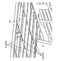
- FIG. 4 is an enlarged perspective view showing a heat dissipation protrusion formed on the lower surface of the scanner casing in the first embodiment of the present invention.
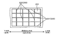
- FIG. 5 is a plan view seen from the lower surface side of the scanner casing showing the heat-dissipating protrusions according to the first embodiment of the present invention.
- FIG. 1 is a perspective view showing a copying machine as an image forming apparatus in Embodiment 1 of the present invention.
- FIG. 2 is a schematic sectional view showing the copying machine according to the first embodiment of the present invention as seen from
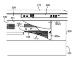
- FIG. 6 is a side view of the copying machine according to the second embodiment of the present invention viewed from the front side.
- FIG. 7 is a perspective view showing a heat dissipation protrusion formed on the lower surface of the scanner casing of the copying machine according to the second embodiment of the present invention.
- FIG. 8 is a view corresponding to FIG. 5 showing Embodiment 2 of the present invention.
- FIG. 9 is a view corresponding to FIG. 6 showing another embodiment of the present invention.
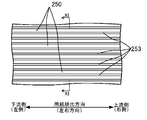
- FIG. 10 is a view corresponding to FIG. 5 showing another embodiment of the present invention.
- 11 is a cross-sectional view taken along line XI-XI in FIG.
- Embodiment 1 1 and 2 show a digital copying machine 1 (hereinafter simply referred to as a copying machine 1) as an image forming apparatus in the present embodiment.
- the copying machine 1 is a so-called in-body discharge type copying machine, and includes a main body casing 100, a scanner casing 200, and a supporting casing 300.
- a scanner unit 210 for reading a document image is accommodated in the scanner housing unit 200.
- An image forming unit 30 for printing a document image read by the scanner unit 210 on the paper P is accommodated in the main body housing unit 100.
- the main body housing unit 100 is disposed below the scanner housing unit 200.
- the scanner casing 200 is supported on the main body casing 100 via the support casing 300.
- the support housing unit 300 extends upward from the upper part of the main body housing unit 100 and supports the scanner housing unit 200 from below.
- a sheet discharge space S is formed by these three casings 100 to 300.
- the scanner casing 200 is made of a substantially rectangular resin material.
- an operation panel 205 is provided for a user to give various operation instructions to the copying machine 1.
- front side the side where the operation panel 205 is located in the copying machine 1
- rear side the opposite side
- left side is “left side”
- right side is “right side”.
- the upper surface of the scanner casing 200 constitutes a document placement surface 200a on which a document is placed.
- a substantially rectangular opening (not shown) is formed on the document placement surface 200a, and contact glass is fitted into the opening.
- the document placement surface 200a is covered with a document cover 220 so that it can be opened and closed.
- the document cover 220 has a rectangular plate shape in plan view, and is supported at the rear edge of the document placement surface 200a through a hinge portion (not shown) so as to be opened and closed.
- the scanner unit 210 optically reads a document placed on the contact glass of the document placement surface 200a and generates image data thereof.
- the scanner unit 210 includes a reading unit 211, a reflection mirror 212, and a CCD sensor 213.
- the reading unit 211 moves in the sub-scanning direction (left-right direction in FIG. 2) while irradiating light from the LED light source 211a toward the original on the contact glass at the time of image reading.
- the reflection mirror 212 guides reflected light from the document to the CCD sensor 213.
- the CCD sensor 213 photoelectrically converts the received light to generate image data of a document image.
- the generated image data is stored in a data storage unit (not shown).
- the main body casing 100 is formed in a substantially rectangular parallelepiped shape, and the image forming section 30 is disposed near the right side wall portion in the lower part in the main body casing 100.
- a paper feeding unit 10 is provided on the left side of the image forming unit 30.
- the paper feed unit 10 includes a paper feed cassette 10a in which sheet-like paper P is accommodated, and a pickup roller 10b for taking out the paper P in the paper feed cassette 10a and sending it out of the cassette.
- the paper P sent out of the cassette from the paper feed cassette 10 a is supplied to the image forming unit 30 via the transport roller pair 11.
- the image forming unit 30 includes a transfer unit 20 that forms a toner image and transfers the toner image onto the paper P, and a fixing unit 40 that fixes the toner image transferred onto the paper P by the transfer unit 20 onto the paper P.
- the transfer unit 20 includes a photosensitive drum 21, a charger 23, an exposure device 25, a developing device 27, and a transfer device 29.
- the transfer unit 20 charges the peripheral surface of the photosensitive drum 21 by the charger 23 and then based on the document image data (image data of the document image generated by the scanner unit 210) on the surface of the photosensitive drum 21 by the exposure device 25.
- An electrostatic latent image is formed by irradiating laser light, and the formed electrostatic latent image is developed by the developing device 27 to form a toner image.
- the transfer unit 20 transfers the toner image to the paper P supplied from the paper supply unit 10 by the transfer device 29 and supplies the transferred paper P to the fixing unit 40.
- the fixing unit 40 includes a fixing roller 40 a and a pressure roller 40 b disposed above the image forming unit 30.
- the fixing roller 40a is heated by an internal heater.
- the paper P supplied from the image forming unit 30 is pressed between the fixing roller 40 a and the pressure roller 40 b to thermally fix the toner image on the paper P.
- the paper P on which the toner image is fixed by the fixing unit 40 is sent upward by the rollers 40a and 40b and the conveyance roller pair 12, and is conveyed into the support housing unit 300 through the vertical conveyance path T1. .
- the support housing part 300 extends upward along the right side wall part from the upper part of the main body housing part 100.
- the space in the support housing unit 300 communicates with the space in the main body housing unit 100.
- a paper discharge port 300 a extending in the front-rear direction is formed in the left side wall portion of the support housing unit 300.
- a horizontal conveyance path T2 connected to the vertical conveyance path T1 is provided in the support housing unit 300.
- a discharge roller pair 13 is provided at the downstream end of the horizontal conveyance path T2.
- the paper P transported into the supporting housing unit 300 through the vertical transport path T1 reaches the discharge roller pair 13 through the horizontal transport path T2. Thereafter, the paper P is discharged from the paper discharge port 300 a to the paper discharge space S by the discharge roller pair 13.
- the discharge direction of the paper P coincides with the left-right direction.
- the paper discharge space S is formed by a part of the lower surface of the scanner housing part 200, the upper surface of the main body housing part 100, and the left side surface of the support housing part 300.
- the rear side of the paper discharge space S is closed by a sheet metal frame 105 that is continuously connected to the rear side wall portion of the main body housing portion 100.
- the left side of the sheet discharge space S is closed by a sheet metal frame 106 that is continuously connected to the left wall of the main body casing 100.
- the sheet discharge space S is open only to the front side.
- a paper discharge tray portion 101 for receiving the paper P discharged from the paper discharge port 300a.
- the paper discharge tray unit 101 is formed on the upper surface of the main body housing unit 100.
- the paper discharge tray 101 has an inclined portion 101a that is inclined upward from the upstream side to the downstream side in the paper discharge direction.
- the paper P discharged to the paper discharge tray portion 101 is positioned by sliding down the inclined portion 101a and coming into contact with the left side surface of the support housing portion 300.
- the user needs to put a hand into the paper discharge space S when collecting the paper P discharged to the paper discharge tray unit 101.
- the user's hand may touch the lower surface of the scanner casing 200 that covers the upper side of the paper discharge space S.
- the lower surface of the scanner casing 200 is heated by the heat generated from the scanner unit 210 and the fixing roller 40a and the retained heat of the paper P that passes through the fixing roller 40a and is discharged to the paper discharge tray unit 101, resulting in a high temperature. easy. Therefore, there is room for improvement from the viewpoint of increasing user safety.
- a heat radiation projection 250 is formed on the surface 201 that forms the paper discharge space S in the lower surface of the scanner casing 200.
- the heat-dissipating protrusions 250 are formed in a lattice shape (an example of a mesh shape) when viewed from the lower surface side of the scanner housing portion 200. More specifically, the heat-dissipation protrusions 250 include a plurality of first plate-like protrusions 251 extending in the paper discharge direction (left-right direction) and a plurality of second plate intersections perpendicular to the first plate-like protrusions 251. And a plate-like protrusion 252. The first and second plate-like protrusions 251 and 252 are formed perpendicular to the lower surface of the scanner housing part 200.
- the first plate-like protrusions 251 are arranged at equal intervals in a direction (front-rear direction) orthogonal to the paper discharge direction.
- the second plate-like protrusions 252 are arranged at equal intervals in the paper discharge direction.
- the protrusion height H1 (see FIG. 4) of the first plate-like protrusion 251 from the lower surface of the scanner casing 200 is the protrusion of the second plate-like protrusion 252 from the lower surface of the scanner casing 200. It is larger than the height H2.
- symbol 300b in FIG. 4 is a vent hole for waste heat.
- the heat radiation protrusion 250 is formed on the surface portion 201 that forms the paper discharge space S on the lower surface of the scanner housing portion 200. Therefore, even if the lower surface of the scanner housing unit 200 is heated by the heat generated by the scanner unit 210 and the fixing roller 40 and the retained heat of the paper P, the heat is radiated to the atmosphere via the protrusions 250. Can do. Therefore, it is possible to suppress the lower surface of the scanner unit 210 from becoming high temperature, and to improve the user's safety when collecting paper.
- the heat dissipation projections 250 are formed in a lattice shape when viewed from the lower surface side of the scanner casing 200.
- the lower surface of the scanner housing unit 200 does not contact the user's hand in a surface shape, but in a lattice shape (mesh shape). . Therefore, it is possible to reduce as much as possible the area of the lower surface of the scanner housing 200 that is likely to become high in temperature and that is in contact with the user's hand.
- the protruding side end portion of the protrusion 250 having a relatively low temperature contacts the user's hand
- the base end portion of the protrusion 250 having a relatively high temperature does not contact the user's hand. Therefore, it is possible to further improve the safety of the user when collecting paper.
- the protrusions 250 function as reinforcing ribs that increase the surface rigidity of the lower surface of the scanner casing 200. Therefore, even if the scanner casing 200 is made of a resin material having lower rigidity than the metal material as in the first embodiment, the surface rigidity of the lower surface of the scanner casing 200 can be sufficiently ensured.
- the heat dissipation protrusion 250 includes a plurality of first plate-like protrusions 251 extending in the paper discharge direction and a plurality of second plate-like protrusions 252 that intersect the first plate-like protrusions 251.
- the protrusion height H1 of the first plate-like protrusion 251 is set larger than the protrusion height H2 of the second plate-like protrusion 252.
- Embodiment 2 >> 6 to 8 show the second embodiment.
- the second embodiment is different from the first embodiment in the shape of the first plate-like protrusion 251 constituting the heat dissipation protrusion 250.
- the same parts as those in the first embodiment are denoted by the same reference numerals, and detailed description thereof is omitted.
- the first plate-like protrusion 251 has a substantially right triangle shape when viewed from the front side.
- the upper end surface of the first plate-like protrusion 251 is connected to the lower surface of the scanner housing unit 200.
- the right end surface of the first plate-like protrusion 251 is formed perpendicular to the lower surface of the scanner housing part 200.
- the lower end surface of the first plate-like projecting portion 251 has a gently inclined surface portion 251a that is gently inclined upward from the right side to the left side (from the upstream side to the downstream side in the paper discharge direction), and an inclination angle that is lower than that of the gently inclined surface portion 251a It is formed with a strong steeply inclined surface portion 251b.
- the right end portion of the gently inclined surface portion 251a is located in the vicinity of the exit side of the paper discharge port 300a and in the vicinity of the upper side.
- the downstream end of the paper P is the steeply inclined surface portion 251b of the first plate-like protrusion 251. (Refer to the two-dot chain line in FIG. 6). Then, the paper P is conveyed downstream along the steeply inclined surface portion 251b, so that the curl of the paper P is reduced or removed. As a result, the stockability of the paper P in the paper discharge space S can be improved.
- the heat-dissipating protrusion 250 is formed by the plate-like protrusions 251 and 252, but is not limited thereto.
- a protrusion 250 is formed between the adjacent grooves 253. You may make it do. According to this, the yield of the material can be improved as compared with the case where the plate-like protrusions 251 and 252 are formed on the lower surface of the scanner casing 200.
- the lower end surface of the first plate-like protrusion 251 is formed by the gently inclined surface portion 251a and the steeply inclined surface portion 251b, but is not limited thereto.
- it may be formed by a curved surface that protrudes toward the discharge tray 101a.
- the heat-dissipating protrusions 250 are formed in a lattice shape when viewed from the lower surface side of the scanner casing 200, but the present invention is not limited to this.
- it may be formed in a honeycomb shape (an example of a mesh shape).
- the protrusion 250 is not necessarily formed in a mesh shape, and may be formed in a radial shape or a cross shape, for example. That is, the protrusion 250 may have any shape as long as it protrudes from the lower surface of the scanner casing 200.
- the rear side and the left side of the paper discharge space S are closed by the sheet metal frame 105 and the sheet metal frame 106, respectively, but the both sheet metal frames 105 and 106 are not necessarily required.
- the copying machine 1 has been described as an example of the image forming apparatus.
- the image forming apparatus according to the present invention is not limited to this, and other images such as a laser printer, a scanner device, or a multifunction peripheral may be used.
- a forming apparatus may be used.
- the electrophotographic image forming apparatus (copier 1) has been described.
- the present invention is not limited to this, and for example, an inkjet image forming apparatus may be employed.
Landscapes
- Physics & Mathematics (AREA)
- General Physics & Mathematics (AREA)
- Engineering & Computer Science (AREA)
- Mechanical Engineering (AREA)
- Life Sciences & Earth Sciences (AREA)
- Atmospheric Sciences (AREA)
- Biodiversity & Conservation Biology (AREA)
- Ecology (AREA)
- Environmental & Geological Engineering (AREA)
- Environmental Sciences (AREA)
- Electrophotography Configuration And Component (AREA)
- Facsimiles In General (AREA)
- Control Or Security For Electrophotography (AREA)
- Separation, Sorting, Adjustment, Or Bending Of Sheets To Be Conveyed (AREA)
- Pile Receivers (AREA)
Abstract
画像形成装置(1)は、原稿画像を読み取るためのスキャナー部(210)が収容されたスキャナー筐体部(200)と、スキャナー部(210)が読み取った原稿画像に基づいて用紙に画像形成処理を施す画像形成部(30)が収容され、スキャナー筐体部(200)よりも下側に配置された本体筐体部(100)と、本体筐体部(100)の上部から上方に延びてスキャナー筐体部(200)を下方から支持する支持筐体部(300)と、スキャナー筐体部(200)と本体筐体部(100)と支持筐体部(300)とによって形成され、用紙が排出される用紙排出空間(S)とを備え、スキャナー筐体部(200)の下面における用紙排出空間(S)を形成する面部(201)には、放熱用の突起(250)が形成されている。
Description
本発明は、胴内排紙型の画像形成装置に関する。
従来より、いわゆる胴内排紙型の画像形成装置は知られている。この画像形成装置は、スキャナー筐体部と、スキャナー筐体部よりも下側に配置された本体筐体部とを有している。スキャナー筐体部には、その上面に載置された原稿を読み取るためのスキャナー部が収容されている。本体筐体部には、用紙に画像形成処理を施すための画像形成部が収容されている。そして、本体筐体部とスキャナー筐体部との間の空間が用紙排出空間として利用されている。
この種の画像形成装置では、スキャナー部からの発熱によって原稿載置面(スキャナー筐体部の上面)が過度に熱せられる場合がある。このため、原稿載置面の温度を低下させてユーザーの安全性を高めるべく、現在までに種々の技術が提案されている。例えば、特許文献1に示すものでは、スキャナー筐体部の内部に冷却ファンを配置して、スキャナー部による原稿画像の読取り時に当該冷却ファンを作動させるようにしている。
ところで、上述した胴内排紙型の画像形成装置では、ユーザーが用紙排出空間に排出された用紙を回収する際に、スキャナー筐体部の下面に触れてしまい易い。このスキャナー筐体部の下面は、その内部に収容されたスキャナー部からの発熱により熱せられて高温になっている。したがって、用紙回収時におけるユーザーの安全性を確保する観点から改良の余地がある。特に、電子写真方式の画像形成装置では、定着ローラー(画像形成部の一構成要素)によりトナーを加熱して用紙に定着させる方式を採用しているため、定着ローラーからの発熱や、定着ローラーを通過後に用紙排出空間に排出された用紙の保有熱等によって、スキャナー部の下面が熱せられ易く、改良の余地が大きい。
そこで、スキャナー筐体部と本体筐体部との距離を大きくとることで、定着ローラーからの発熱や用紙の保有熱がスキャナー筐体部の下面に伝わり難くすることが考えられる。しかしこの場合、装置の全高が高くなってしまうという問題がある。
また、特許文献1に示すように、スキャナー筐体部内に冷却ファンを配置することも考えられるものの、この場合、スキャナー筐体部が冷却ファンの配置スペース分だけ大型化するという問題がある。また、冷却ファンを設けることによりコストが増加するという問題がある。
本発明は、かかる点に鑑みてなされたものであり、その目的とするところは、胴内排紙型の画像形成装置において、装置の小型化及び低コスト化を図りながら、スキャナー筐体部の下面が高温化することによるユーザーへの影響を低減して、ユーザーの安全性を高めることにある。
本発明の一の局面に係る画像形成装置は、スキャナー筐体部と、本体筐体部と、支持筐体部と、用紙排出空間とを備える。上記スキャナー筐体部には、原稿画像を読み取るためのスキャナー部が収容される。上記本体筐体部は、上記スキャナー部が読み取った原稿画像に基づいて用紙に画像形成処理を施す画像形成部が収容され、上記スキャナー筐体部よりも下側に配置されている。上記支持筐体部は、上記本体筐体部の上部から上方に延びて上記スキャナー筐体部を下方から支持する。上記用紙排出空間は、上記スキャナー筐体部と上記本体筐体部と上記支持筐体部とによって形成され、上記用紙が排出される。そして、上記スキャナー筐体部の下面における上記用紙排出空間を形成する面部には、放熱用の突起が形成されている。
本発明によれば、胴内排紙型の画像形成装置において、装置の小型化及び低コスト化を図りながら、スキャナー筐体部の下面が高温化することによるユーザーへの影響を低減して、ユーザーの安全性を高めることができる。
以下、本発明の実施形態を図面に基づいて詳細に説明する。尚、本発明は、以下の実施形態に限定されるものではない。
《実施形態1》
図1及び図2は、本実施形態における画像形成装置としてのデジタル複写機1(以下、単に複写機1という)を示している。この複写機1は、いわゆる胴内排紙型の複写機であって、本体筐体部100とスキャナー筐体部200と支持筐体部300とを有している。スキャナー筐体部200内には、原稿画像を読み取るためのスキャナー部210が収容されている。本体筐体部100内には、スキャナー部210が読み取った原稿画像を用紙Pに印刷するための画像形成部30が収容されている。本体筐体部100は、スキャナー筐体部200よりも下側に配置されている。スキャナー筐体部200は、本体筐体部100に対して支持筐体部300を介して支持されている。支持筐体部300は、本体筐体部100の上部から上方に延びてスキャナー筐体部200を下方から支持している。そして、これら3つの筐体部100~300によって用紙排出空間Sが形成されている。
図1及び図2は、本実施形態における画像形成装置としてのデジタル複写機1(以下、単に複写機1という)を示している。この複写機1は、いわゆる胴内排紙型の複写機であって、本体筐体部100とスキャナー筐体部200と支持筐体部300とを有している。スキャナー筐体部200内には、原稿画像を読み取るためのスキャナー部210が収容されている。本体筐体部100内には、スキャナー部210が読み取った原稿画像を用紙Pに印刷するための画像形成部30が収容されている。本体筐体部100は、スキャナー筐体部200よりも下側に配置されている。スキャナー筐体部200は、本体筐体部100に対して支持筐体部300を介して支持されている。支持筐体部300は、本体筐体部100の上部から上方に延びてスキャナー筐体部200を下方から支持している。そして、これら3つの筐体部100~300によって用紙排出空間Sが形成されている。
上記スキャナー筐体部200は、略直方体状の樹脂材により構成されている。スキャナー筐体部200の側面には、ユーザーが複写機1に対して各種の操作指示を行うための操作パネル205が設けられている。以下の説明において、複写機1における操作パネル205が位置する側を「前側」とし、その反対側を「後側」とする。また、複写機1を前側から見た場合における左側を「左側」とし、右側を「右側」とする。
上記スキャナー筐体部200の上面は、原稿が載置される原稿載置面200aを構成している。この原稿載置面200aには略矩形状の開口部(図示省略)が形成されており、この開口部にはコンタクトガラスが嵌め込まれている。原稿載置面200aは、原稿カバー220によって開閉可能に覆われている。原稿カバー220は平面視で矩形板状をなしていて、原稿載置面200aの後側の端縁部にヒンジ部(図示省略)を介して開閉自在に支持されている。
上記スキャナー部210は、原稿載置面200aのコンタクトガラス上に載置された原稿を光学的に読み取ってその画像データを生成する。具体的には、スキャナー部210は、読取りユニット211と、反射ミラー212と、CCDセンサ213とを有している。読取りユニット211は、画像読取り時には、LED光源211aよりコンタクトガラス上の原稿に向けて光を照射しながら副走査方向(図2の左右方向)に移動する。反射ミラー212は、原稿からの反射光をCCDセンサ213へと導く。CCDセンサ213は、受光した光を光電変換して原稿画像の画像データを生成する。生成された画像データは、不図示のデータ記憶部に記憶される。
上記本体筐体部100は略直方体状に形成されており、上記画像形成部30は、本体筐体部100内の下部における右側壁部寄りに配置されている。画像形成部30の左側には、給紙部10が設けられている。給紙部10は、シート状の用紙Pが収容される給紙カセット10aと、該給紙カセット10a内の用紙Pを取り出して該カセット外に送り出すためのピックアップローラー10bとを有している。給紙カセット10aよりカセット外に送り出された用紙Pは、搬送ローラー対11を介して画像形成部30に供給される。
画像形成部30は、トナー像を形成して用紙Pに転写する転写部20と、転写部20によって用紙Pに転写されたトナー像を用紙Pに定着させる定着部40とを有している。
転写部20は、感光ドラム21、帯電器23、露光装置25、現像装置27、及び転写器29を有している。転写部20は、帯電器23によって感光ドラム21の周面を帯電させた後、露光装置25によって感光ドラム21の表面に原稿画像データ(スキャナー部210により生成された原稿画像の画像データ)に基づくレーザー光を照射することで静電潜像を形成し、形成した静電潜像を現像装置27によって現像することでトナー像を形成する。そして、転写部20は、転写器29によって給紙部10より供給された用紙Pに対してトナー像を転写すると共に、該転写後の用紙Pを定着部40に供給する。
定着部40は、画像形成部30の上方に配置された定着ローラー40a及び加圧ローラー40bを有している。定着ローラー40aは、その内部のヒーターによって加熱される。定着部40では、画像形成部30より供給される用紙Pを定着ローラー40a及び加圧ローラー40b間で加圧することにより、当該用紙Pにトナー像を熱定着させる。そして、定着部40にてトナー像が定着された用紙Pは、両ローラー40a,40b及び搬送ローラー対12により上方に送りだされて、垂直搬送路T1を通じて支持筐体部300内に搬送される。
支持筐体部300は、本体筐体部100の上部からその右側壁部に沿って上方に延びている。支持筐体部300内の空間は、本体筐体部100内の空間に連通している。支持筐体部300の左側壁部には、前後方向に延びる用紙排出口300aが形成されている。支持筐体部300内には、垂直搬送路T1に繋がる水平搬送路T2が設けられている。水平搬送路T2の下流側端部には排出ローラー対13が設けられている。上記垂直搬送路T1を通じて支持筐体部300内に搬送された用紙Pは、水平搬送路T2を通って上記排出ローラー対13に達する。その後、用紙Pは、排出ローラー対13によって用紙排出口300aから用紙排出空間Sへと排出される。この用紙Pの排出方向は、左右方向に一致している。
用紙排出空間Sは、スキャナー筐体部200の下面の一部と、本体筐体部100の上面と、支持筐体部300の左側面とによって形成されている。用紙排出空間Sの後側は、本体筐体部100の後側壁部に連続的に繋がる板金フレーム105によって閉塞されている。用紙排出空間Sの左側は、本体筐体部100の左側壁部に連続的に繋がる板金フレーム106によって閉塞されている。そうして、用紙排出空間Sは前側にのみ開放している。
用紙排出空間Sの底部には、用紙排出口300aから排出される用紙Pを受け止める排紙トレイ部101が形成されている。排紙トレイ部101は、本体筐体部100の上面に形成されている。排紙トレイ部101は、用紙排出方向の上流側から下流側に向かって上方に傾斜する傾斜部101aを有している。排紙トレイ部101に排出された用紙Pは、この傾斜部101aを滑り落ちて支持筐体部300の左側面に当接することで位置決めされる。
ところで、上記胴内排紙型の複写機1では、排紙トレイ部101に排出された用紙Pを回収する際に、ユーザーが用紙排出空間S内に手を入れる必要がある。このとき、ユーザーの手が用紙排出空間Sの上側を覆うスキャナー筐体部200の下面に触れてしまう場合がある。このスキャナー筐体部200の下面は、スキャナー部210及び定着ローラー40aからの発熱や、定着ローラー40aを通過して排紙トレイ部101に排出された用紙Pの保有熱により熱せられて高温になり易い。したがって、ユーザーの安全性を高める観点から改良の余地がある。
そこで、本実施形態では、スキャナー筐体部200の下面のうち用紙排出空間Sを形成する面部201に放熱用の突起250を形成するようにしている。
図3~図5に示すように、この放熱用の突起250は、スキャナー筐体部200の下面側から見て格子状(網目状の一例)に形成されている。より詳しくは、放熱用の突起250は、用紙排出方向(左右方向)に延びる複数の第1板状突起部251と、上記第1板状突起部251に対して直角に交差する複数の第2板状突起部252とを有している。第1及び第2板状突起部251,252は、スキャナー筐体部200の下面に垂直に形成されている。
第1板状突起部251は、用紙排出方向に直交する方向(前後方向)に等間隔に配置されている。第2板状突起部252は、用紙排出方向に等間隔に配置されている。上記第1板状突起部251の上記スキャナー筐体部200の下面からの突出高さH1(図4参照)は、上記第2板状突起部252の上記スキャナー筐体部200の下面からの突出高さH2よりも大きい。尚、図4中の符号300bは廃熱用の通気口である。
以上説明したように、上記実施形態1では、スキャナー筐体部200の下面における上記用紙排出空間Sを形成する面部201に、放熱用の突起250を形成するようにした。したがって、スキャナー筐体部200の下面が、スキャナー部210や定着ローラー40の発熱、及び用紙Pの保有熱等によって熱せられたとしても、その熱を上記突起250を介して大気中に放熱することができる。よって、スキャナー部210の下面が高温化するのを抑制し、延いては、用紙回収時等におけるユーザーの安全性を向上させることができる。しかも、上記構成によれば、スキャナー筐体部200内に冷却ファンを設けたり、スキャナー筐体部200と本体筐体部100との距離d(図2参照)を大きくとったりする必要もないので、複写機1全体の小型化及び低コスト化を図ることができる。
また、上記実施形態1では、放熱用の突起250は、スキャナー筐体部200の下面側から見て格子状に形成されている。
したがって、スキャナー筐体部200の下面にユーザーが手を触れた場合に、スキャナー筐体部の下面がユーザーの手に面状に接触するのではなく格子状(網目状)に接触することとなる。したがって、高温になり易いスキャナー筐体部200の下面のうちユーザーの手に接触する部分の面積を極力低減することができる。また、比較的温度が低い突起250の突出側端部がユーザーの手に接触することはあっても、比較的温度が高い突起250の基端部がユーザーの手に接触することはない。よって、用紙回収時等におけるユーザーの安全性をより一層高めることができる。
また、突起250を格子状に形成することにより、当該突起250がスキャナー筐体部200の下面の面剛性を高める補強リブとして機能する。よって、上記実施形態1の如くスキャナー筐体部200を金属材料に比べて剛性が低い樹脂材料で構成したとしても、スキャナー筐体部200の下面の面剛性を十分に確保することができる。
また、上記放熱用の突起250は、用紙排出方向に延びる複数の第1板状突起部251と、第1板状突起部251に交差する複数の第2板状突起部252とを有しており、第1板状突起部251の突出高さH1は、上記第2板状突起部252の突出高さH2よりも大きく設定されている。
したがって、例えば定着ローラー40aより用紙Pに加わる熱に起因して用紙排出口300aから排出される用紙Pの下流側端部が上流側端部に比べて上方に反り上がっている場合に(図2の二点鎖線参照)、用紙Pの下流側端部が第2板状突起部252に引っ掛かるのを抑制することができる。延いては、用紙排出空間S内における用紙Pのストック性を向上させることできる。
《実施形態2》
図6~図8は、実施形態2を示している。この実施形態2は、放熱用の突起250を構成する第1板状突起部251の形状が上記実施形態1とは異なっている。尚、以降の実施形態において、実施形態1と同じ部分については同じ符号を付して、その詳細な説明を省略する。
図6~図8は、実施形態2を示している。この実施形態2は、放熱用の突起250を構成する第1板状突起部251の形状が上記実施形態1とは異なっている。尚、以降の実施形態において、実施形態1と同じ部分については同じ符号を付して、その詳細な説明を省略する。
すなわち、本実施形態では、第1板状突起部251は、前側から見て略直角三角形状をなしている。詳しくは、第1板状突起部251の上端面は、スキャナー筐体部200の下面に連結されている。第1板状突起部251の右側端面は、スキャナー筐体部200の下面に対して垂直に形成されている。第1板状突起部251の下端面は、右側から左側(用紙排出方向の上流側から下流側)に向かって上方に緩やかに傾斜する緩傾斜面部251aと、緩傾斜面部251aよりも傾斜角が強い急傾斜面部251bとで形成されている。緩傾斜面部251aの右側端部は、用紙排出口300aの出口側近傍で且つ上側近傍に位置している。
上記実施形態2では、用紙排出口300aから排出された用紙が上方に反り上がるようにカールしている場合には、用紙Pの下流側端部が第1板状突起部251の急傾斜面部251bに当接する(図6の二点鎖線参照)。そして、用紙Pが急傾斜面部251bに沿って下流側に搬送されることで、用紙Pのカールが緩和又は除去される。延いては、用紙排出空間S内における用紙Pのストック性を向上させることができる。
また、上記実施形態2では、スキャナー筐体部200の下面に放熱用の突起250が形成されているため、上記実施形態1と同様の作用効果を得ることができる。
《他の実施形態》
上記各実施形態では、放熱用の突起250を板状突起部251,252によって形成するようにしているが、これに限ったものではない。例えば、図9及び図10に示すように、スキャナー筐体部200の下面に用紙排出方向に延びる複数の溝部253を形成することにより、隣り合う溝部253と溝部253との間に突起250を形成するようにしてもよい。これによれば、スキャナー筐体部200の下面に板状突起部251,252を形成する場合に比べて、材料の歩留まりを向上させることができる。
上記各実施形態では、放熱用の突起250を板状突起部251,252によって形成するようにしているが、これに限ったものではない。例えば、図9及び図10に示すように、スキャナー筐体部200の下面に用紙排出方向に延びる複数の溝部253を形成することにより、隣り合う溝部253と溝部253との間に突起250を形成するようにしてもよい。これによれば、スキャナー筐体部200の下面に板状突起部251,252を形成する場合に比べて、材料の歩留まりを向上させることができる。
上記実施形態2では、第1板状突起部251の下端面は、緩傾斜面部251aと急傾斜面部251bとによって形成されているが、これに限ったものではない。例えば、図11に示すように、排紙トレイ101a側に凸となる湾曲面によって形成されていてもよい。
上記各実施形態では、放熱用の突起250は、スキャナー筐体部200の下面側から見て格子状に形成されているが、これに限ったものではない。例えば、ハニカム状(網目状の一例)に形成されていてもよい。また、上記突起250は、必ずしも網目状に形成されている必要はなく、例えば、放射状や十字状に形成されていてもよい。すなわち、突起250は、スキャナー筐体部200の下面から突出していれば、如何なる形状であってもよい。
上記各実施形態では、用紙排出空間Sの後側及び左側がそれぞれ、板金フレーム105及び板金フレーム106により閉塞されているが、両板金フレーム105,106は必ずしも必要ではない。
上記各実施形態では、画像形成装置の一例として、複写機1について説明したが、本発明に係る画像形成装置は、これに限らず、例えばレーザープリンター、スキャナー装置、又は複合機等の他の画像形成装置としてもよい。
上記各実施形態では、電子写真方式の画像形成装置(複写機1)について説明したが、これに限ったものではなく、例えばインクジェット方式の画像形成装置を採用してもよい。
Claims (4)
- 原稿画像を読み取るためのスキャナー部が収容されたスキャナー筐体部と、
上記スキャナー部が読み取った原稿画像に基づいて用紙に画像形成処理を施す画像形成部が収容され、上記スキャナー筐体部よりも下側に配置された本体筐体部と、
上記本体筐体部の上部から上方に延びて上記スキャナー筐体部を下方から支持する支持筐体部と、
上記スキャナー筐体部と上記本体筐体部と上記支持筐体部とによって形成され、上記用紙が排出される用紙排出空間と、
を備え、
上記スキャナー筐体部の下面における上記用紙排出空間を形成する面部には、放熱用の突起が形成されている、画像形成装置。 - 請求項1記載の画像形成装置において、
上記放熱用の突起は、上記スキャナー筐体部の下面側から見て網目状に形成されている、画像形成装置。 - 請求項2記載の画像形成装置において、
上記支持筐体部における上記用紙排出空間を形成する面部には、上記用紙を該用紙排出空間に排出するための用紙排出口が形成され、
上記放熱用の突起は、互いに間隔を空けて配置され且つ用紙排出方向に延びる複数の第1板状突起部と、互いに間隔を空けて配置され且つ上記第1板状突起部に交差する複数の第2板状突起部とを有し、
上記第1板状突起部の上記スキャナー筐体部の下面からの突出高さは、上記第2板状突起部の上記スキャナー筐体部の下面からの突出高さよりも大きい、画像形成装置。 - 請求項2記載の画像形成装置において、
上記支持筐体部における上記用紙排出空間を形成する面部には、上記用紙を該用紙排出空間に排出するための用紙排出口が形成され、
上記放熱用の突起は、互いに間隔を空けて配置され且つ用紙排出方向に延びる複数の第1板状突起部と、互いに間隔を空けて配置され且つ上記第1板状突起部に交差する複数の第2板状突起部とを有し、
上記用紙排出口から排出される用紙には、その排出方向の下流側端部が上流側端部に比べて上方に反り上がるようにカールする用紙が含まれており、
上記第1板状突起部の下端面は、上記用紙排出口から排出される上記カールした用紙に当接することにより当該用紙のカールを緩和又は除去するように形成されている、画像形成装置。
Applications Claiming Priority (2)
| Application Number | Priority Date | Filing Date | Title |
|---|---|---|---|
| JP2013-172738 | 2013-08-22 | ||
| JP2013172738A JP2016180770A (ja) | 2013-08-22 | 2013-08-22 | 画像形成装置 |
Publications (1)
| Publication Number | Publication Date |
|---|---|
| WO2015025641A1 true WO2015025641A1 (ja) | 2015-02-26 |
Family
ID=52483423
Family Applications (1)
| Application Number | Title | Priority Date | Filing Date |
|---|---|---|---|
| PCT/JP2014/068769 Ceased WO2015025641A1 (ja) | 2013-08-22 | 2014-07-15 | 画像形成装置 |
Country Status (2)
| Country | Link |
|---|---|
| JP (1) | JP2016180770A (ja) |
| WO (1) | WO2015025641A1 (ja) |
Citations (7)
| Publication number | Priority date | Publication date | Assignee | Title |
|---|---|---|---|---|
| JP2002338122A (ja) * | 2001-05-18 | 2002-11-27 | Canon Inc | シート積載装置及びこれを備えた画像形成装置 |
| JP2005053648A (ja) * | 2003-08-05 | 2005-03-03 | Canon Inc | 画像形成装置 |
| JP2006003649A (ja) * | 2004-06-17 | 2006-01-05 | Brother Ind Ltd | 画像形成装置 |
| JP2009037188A (ja) * | 2007-01-31 | 2009-02-19 | Ricoh Co Ltd | 画像形成装置 |
| JP2009139673A (ja) * | 2007-12-07 | 2009-06-25 | Kyocera Mita Corp | 画像形成装置 |
| JP2010074625A (ja) * | 2008-09-19 | 2010-04-02 | Konica Minolta Business Technologies Inc | 画像形成装置 |
| JP2012123022A (ja) * | 2010-12-06 | 2012-06-28 | Sharp Corp | 画像形成装置 |
-
2013
- 2013-08-22 JP JP2013172738A patent/JP2016180770A/ja active Pending
-
2014
- 2014-07-15 WO PCT/JP2014/068769 patent/WO2015025641A1/ja not_active Ceased
Patent Citations (7)
| Publication number | Priority date | Publication date | Assignee | Title |
|---|---|---|---|---|
| JP2002338122A (ja) * | 2001-05-18 | 2002-11-27 | Canon Inc | シート積載装置及びこれを備えた画像形成装置 |
| JP2005053648A (ja) * | 2003-08-05 | 2005-03-03 | Canon Inc | 画像形成装置 |
| JP2006003649A (ja) * | 2004-06-17 | 2006-01-05 | Brother Ind Ltd | 画像形成装置 |
| JP2009037188A (ja) * | 2007-01-31 | 2009-02-19 | Ricoh Co Ltd | 画像形成装置 |
| JP2009139673A (ja) * | 2007-12-07 | 2009-06-25 | Kyocera Mita Corp | 画像形成装置 |
| JP2010074625A (ja) * | 2008-09-19 | 2010-04-02 | Konica Minolta Business Technologies Inc | 画像形成装置 |
| JP2012123022A (ja) * | 2010-12-06 | 2012-06-28 | Sharp Corp | 画像形成装置 |
Also Published As
| Publication number | Publication date |
|---|---|
| JP2016180770A (ja) | 2016-10-13 |
Similar Documents
| Publication | Publication Date | Title |
|---|---|---|
| JP2005077478A (ja) | 画像形成装置 | |
| JP5948909B2 (ja) | 画像形成装置 | |
| JP4577202B2 (ja) | 読取機能付き画像形成装置 | |
| JP2004340988A (ja) | 画像形成装置 | |
| CN104816972A (zh) | 图像形成装置 | |
| CN103853001B (zh) | 包括可动引导单元的成像设备 | |
| CN103853002B (zh) | 成像设备和定影设备 | |
| CN100485540C (zh) | 成像设备的卡纸排除结构 | |
| JP2016180770A (ja) | 画像形成装置 | |
| CN203164595U (zh) | 图像形成装置 | |
| JP4996674B2 (ja) | 光走査装置及びこれを備えた画像形成装置 | |
| JP2002297002A (ja) | プロセスカートリッジおよび画像形成装置 | |
| JP2002287602A (ja) | 画像形成装置 | |
| JP2012123022A (ja) | 画像形成装置 | |
| JP5223187B2 (ja) | 画像形成装置 | |
| US9304471B2 (en) | Image forming apparatus, discharge tray used in image forming apparatus | |
| JP4508321B2 (ja) | 画像形成装置 | |
| JP5316106B2 (ja) | 画像形成装置 | |
| US20260044109A1 (en) | Structure for releasing heat generated inside of image forming apparatus | |
| JP6544301B2 (ja) | 画像形成装置 | |
| JP4107321B2 (ja) | 画像形成装置 | |
| US7693444B2 (en) | Image reading and recording apparatus having a cartridge dismounting space between a fixing unit and an exposing unit | |
| JP7040274B2 (ja) | 画像形成装置 | |
| CN104007635B (zh) | 图像形成装置 | |
| JP2014164008A (ja) | 画像形成装置 |
Legal Events
| Date | Code | Title | Description |
|---|---|---|---|
| 121 | Ep: the epo has been informed by wipo that ep was designated in this application |
Ref document number: 14838379 Country of ref document: EP Kind code of ref document: A1 |
|
| NENP | Non-entry into the national phase |
Ref country code: DE |
|
| NENP | Non-entry into the national phase |
Ref country code: JP |
|
| 122 | Ep: pct application non-entry in european phase |
Ref document number: 14838379 Country of ref document: EP Kind code of ref document: A1 |